

Page 1

ACC Programmer’s Reference Guide
Edition 9
HP 9000 Networking
Manufacturing Part Number: Z7487-90002
E0400
© Copyright 2000 Hewlett-Packard Company, All rights reserved
Page 2

2
Page 3

Legal Notices
The information in this document is subject to change without notice.
Hewlett-Packard makes no warranty of any kind with regard to this
manual, including, but not limited to, the implied warranties of
merchantability and fitness for a particular purpose. Hewlett-Packard
shall not be held liable for errors contained herein or direct, indirect,
special, incidental or consequential damages in connection with the
furnishing, performance, or use of this material.
Warranty. A copy of the specific warranty terms applicable to your
Hewlett- Packard product and replacement parts can be obtained from
your local Sales and Service Office.
Restricted Rights Legend. Use, duplication or disclosure by the U.S.
Government is subject to restrictions as set forth in subparagraph (c) (1)
(ii) of the Rights in Technical Data and Computer Software clause at
DFARS 252.227-7013 for DOD agencies, and subparagraphs (c) (1) and
(c) (2) of the Commercial Computer S oftware Restricted Rights clause at
FAR 52.227-19 for other agencies.
HEWLETT-PACKARD COMPANY 3000 Hanover Street Palo Alto,
California 94304 U.S.A.
Use of this manual and flexible disk(s) or tape cartridge(s) supplied for
this pack is restricted to this product only. Additional copies of the
programs may be made for security and back-up purposes only. Resale of
the programs in their present form or with alterations, is expressly
prohibited.
Copyright Notices. ©copyright 1983-2000 Hewlett-Packard Company,
all rights reserved.
Reproduction, adaptation, or translation of this document without prior
written permission is prohibited, except as allowed under the copyright
laws.
©copyright 1979, 1980, 1983, 1985-93 Regents of the University of
California.
3
Page 4

This software is based in part on the Fourth Berkeley Software
Distribution under license from the Regents of the University of
California.
©copyright 1980, 1984, 1986 Novell, Inc.
©copyright 1986-1992 Sun Microsystems, Inc.
©copyright 1985-86, 1988 Massachusetts Institute of Technology.
©copyright 1989-93 The Open Software Foundation, Inc.
©copyright 1986 Digital Equipment Corporation.
©copyright 1990 Motorola, Inc.
©copyright 1990, 1991, 1992 Cornell University
©copyright 1989-1991 The University of Maryland
©copyright 1988Carnegie Mellon University
©copyright 1989-1997 Data Connection Limited
TrademarkNotices UNIXisaregistered trademark in the UnitedStates
and other countries, licensed exclusively through X/Open Company
Limited.
X Window System is a trademark of the Massachusetts Institute of
Technology.
MS-DOS and Microsoft are U.S. registered trademarks of Microsoft
Corporation.
OSF/Motif is a trademark of the Open Software Foundation, Inc. in the
U.S. and other countries.
4
Page 5

Printing History
The manual publishing date and part number indicate its current
edition. The publishing date will change when a new edition is
published. Minor changes may be made without changing the publishing
date. The manual part number will change when extensive changes are
made.
Manual updates may be issued between editions to correct errors or
document product changes. To ensure t hat you receive the updated or
new editions, you should subscribe to the appropriate product support
service.See your HP sales representativefor details.
First Edition Dec 1992 Release 1.0
Second Edition Mar 1994 Release 2.1
Third Edition April 1995 Release 2.2
Fourth Edition September 1995 Release B.02.20 (HP-UX 10.01)
Fifth Edition March 1996 Release B.02.21 (HP-UX 10.01)
Sixth Edition January 1997 Release B.02.30
Seventh Edition August 1997 Release B.02.39 (HP-UX 10.10)
Release B.02.40 (HP-UX 10.20)
Eighth Edition October 1998 Release B.03.01 (HP-UX 11.0)
Ninth Edition April 2000 Release B.03.10 (HP-UX 11.0)
5
Page 6

Related Documentation
The documentation available for the Multiprotocol ACC family of
products includes the following hardware and software manuals:
Hardware Manuals
• 8 Channel HP-PB ACC Multiplexer Hardware Installation and
Reference Manual
• 8 Channel EISA ACC Multiplexer Hardware Installation and
Reference Manual
• 8 Channel PCI ACC Multiplexer Hardware Installation and Reference
Manual
• 2 Channel (HP-PB) ACC Multiplexer Hardware Installation and
Reference Manual
• 4-Chan. T1/E1 (HP-PB) ACC Multiplexer Hardware Installation and
Reference Manual
Software Manuals
• ACC Installation and Configuration Guide
• ACC Utilities Reference Guide
• ACC Programmer’s Reference Guide
• ACC Error Guide
• HDLC Frame Protocol User’s Guide
• ACC X.25 Protocol User’s Guide
• ACC X.25/ISDN Data Analyzer User’s Guide
• ACC HDLC/LAP-B (ABM) Protocol User’s Guide
• ACC HDLC/LAP-D Protocol User’s Guide
• HDLC-NRM (SDLC) Protocol User’s Guide
• X.25/ACC Installation and Configuration Guide
• X.25/ACC Update Guide
• X.25/9000 User’s Guide
• X.25/9000 Programmer’s Guide
6
Page 7

Contents
1. ZCOM Subsystem
Introduction................................................12
ZCOMSoftwareOverview ....................................13
ZCOMConcepts.............................................17
ProgramZLUs............................................19
TerminalZLUs............................................19
UserInterface..............................................21
References.................................................22
2. ZCOM Message Handling
Overview ..................................................24
ZLUDefinition..............................................25
ProgramZLUs............................................25
TerminalZLUs............................................25
MappedZLUs.............................................26
MessageQueuing............................................27
Priorities...................................................29
Multiplexing................................................30
OutboundMultiplexing.....................................31
InboundMultiplexing.......................................32
TerminalState..............................................34
ErrorHandling .............................................35
7
Page 8

Contents
3. ZCOM Tables and Data Structures
Introduction...............................................38
MemoryOrganization.......................................39
Differencesin32-bitand64-bitDataStructures..................40
ZCOMHeaderStructure.....................................42
NodeEntriesTable..........................................54
ZLUTables................................................ 57
IndividualZLUEntries ....................................57
LogicalTerminalTables...................................... 60
PhysicalTerminalTables..................................... 66
InterfaceTable.............................................75
ResponseRecords...........................................94
QueueHeader.............................................. 97
DataBufferPool...........................................102
OrganizationofBufferPool ................................ 102
MessageHeader........................................... 107
MessageHeader(zmhd_type)............................... 107
MessageIDHeader(zmid_type) ............................ 108
MessageRequestHeader(zmrq_type) .......................111
SystemEventMessage(zevent_type)........................113
ZCOMKernelData ........................................118
NCARD ................................................ 118
HPATable..............................................118
SYS....................................................122
HP ....................................................126
LINFO.................................................126
8
Page 9

Contents
4. ZCOM C I/F Library Routines
Introduction...............................................130
Initializationcall .........................................131
Interfaceconfigurationcall.................................131
ZLUconfigurationcalls....................................131
Datastorageallocationcalls................................131
ZLUinformationcalls .....................................132
ZLUDefinition...........................................134
ManPages................................................135
GETDEVICE(3X)..........................................136
LTFIND(3X) ..............................................140
LTQDGET(3X) ............................................144
LTQDPUT(3X) ............................................147
MAKEZLUNAME(3X)......................................150
PTFIND(3X)..............................................153
ZCLOS(3X)...............................................157
ZCNTL(3X)...............................................160
ZCOMERROR(3X).........................................167
ZCOMLNAME(3X).........................................169
ZCOMLOG(3X)............................................171
ZCOMSTATUS(3X).........................................176
ZCONFIG(3X).............................................178
ZEVENT_RCVR (3X). . . . ....................................209
ZGET_SHRCVR_LIST (3X) . . . . . . . . . . . . . . ....................214
ZINFO(3X) ...............................................217
9
Page 10

Contents
ZINIT(3X) ...............................................221
ZLTMG(3X).............................................. 224
ZLTMX(3X) ..............................................227
ZLTQUEUE(3X) ..........................................230
ZLTSTORE(3X)...........................................234
ZLTUP(3X)...............................................237
ZLUOPEN(3X)............................................ 240
ZMAPR(3X)..............................................243
ZNAME(3X)..............................................245
ZOPEN(3X).............................................. 248
ZPEEK(3X) ..............................................252
zport(3X) ................................................254
ZPTUP(3X)...............................................262
ZQMVE(3X) .............................................264
ZQSZE(3X)...............................................266
ZREAD (3X) . . ............................................ 269
ZRNTIMER(3X)........................................... 275
ZSEND(3X) .............................................. 278
ZSETQL(3X) ............................................. 288
ZSET_RCVR(3X)..........................................291
ZTIMR(3X)...............................................295
10
Page 11

1 ZCOM Subsystem
11
Page 12

ZCOM Subsystem
Introduction
Introduction
The ZCOM Subsystem consists of software and firmware t hat provide
the base set of features for the ACC Product family. It consists of:
• HP-UX interface drivers that communicate with the ACC Mux cards
• the ZCOM Mux Kernel which is an operating system that is
downloaded to the ACC Mux cards
• a set of daemon and utility programs that provide and facilitate
access to the ZCOM Subsystem
• a library of routines t hat provides a comprehensive user interface t o
the ZCOM Subsystem.
The ZCOM Subsystem also provides a powerful framework for
experienced data communication programmers to develop customized
protocols for specialized data communication applications.
This document describes the programmatic interface to the ZCOM
Subsystem. It describes the ZCOM Subsystem tables, buffers, and
routines, and how they are used to achieve program-to-device and
program-to-program communication. It als o contains information
required when writing application programs to take advantage of ACC
product features, such as:
• remote node access
Thisfeatureallowsprogrammaticrequeststoberoutedtoeithera
Mux card that is connected to the system on which the request is
made, or to a program or Mux card on a remote system.
• dual interface Mux panel configurations
This feature allows two systems to connect to a single Mux panel.
• multiple protocol support
• true multi-thread programming support
• 64-bit programming support
12 Chapter1
Page 13

ZCOM Subsystem
ZCOM Software Overview
ZCOM Software Overview
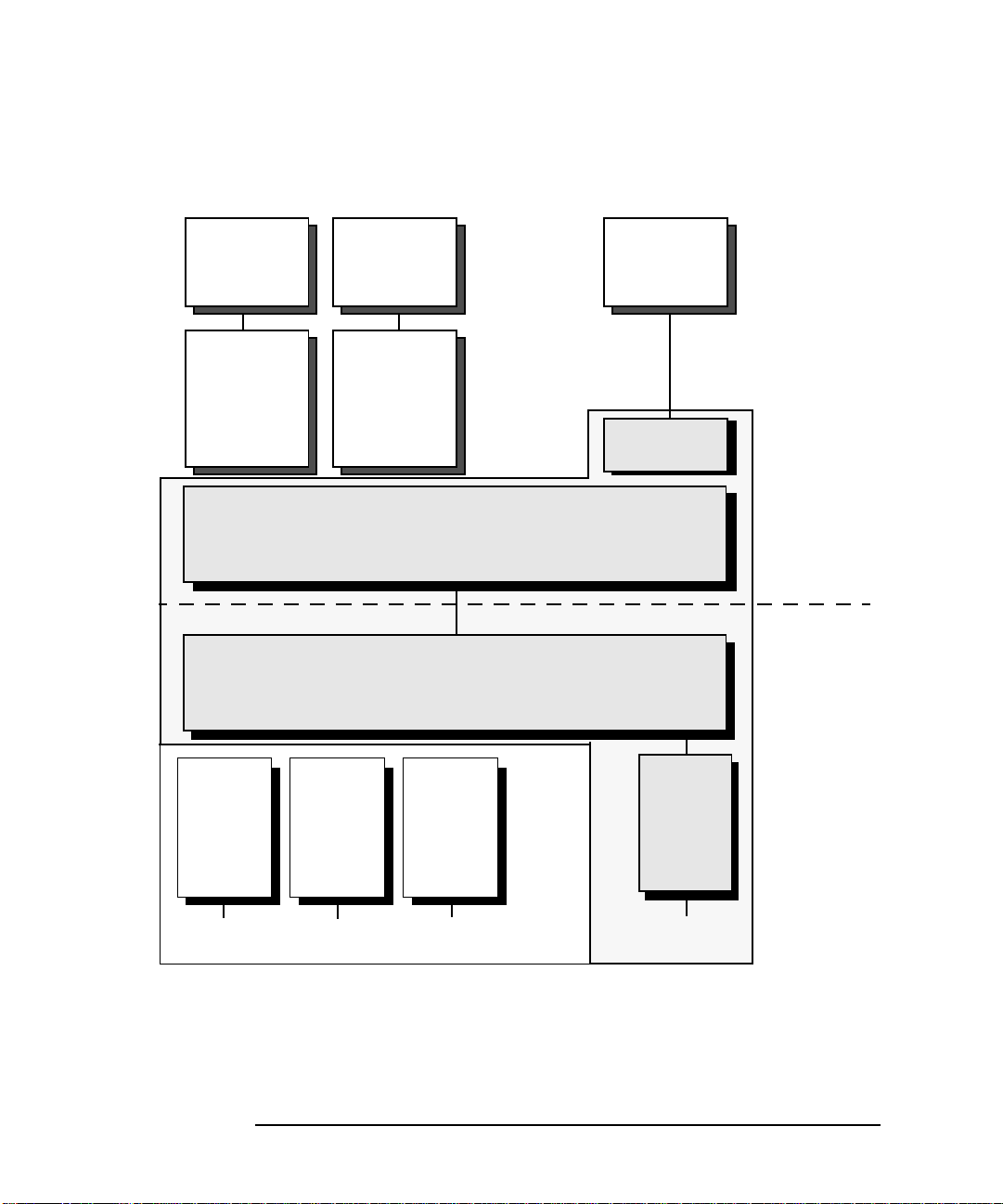
Figure 1-1 on page 14 presents an architectural overview of the ZCOM
Subsystem.
The ZCOM application interface provides low level access to the ZCOM
Subsystem. Application programs make requests via the ZCOM library
routines which are then communicated to the firmware on the ACC Mux
card via the HP-UX drivers.
The firmware which runs on the ACC Mux card includes the ZCOM Mux
kernel software plus ZCOM protocol modules. The ZCOM protocol
modules provide the protocol specific firmware that runs on the ACC
Mux card
Note that the highlighted area in Figure 1-1 shows which software
components are provided by the base ZCOM Subsystem. Only protocol
modules used for loopback testing, and for monitoring the health of the
ACC Mux card and panel are provided with the base ZCOM Subsystem.
Protocol specific modules, such as X.25, are added to the ZCOM
Subsystem as separate products. The Protocol User’s Guides provided
with these products must be used in conjunction with this Programmer’s
Reference Guide when writing ZCOM application program
.
s.
Chapter 1 13
Page 14
ZCOM Subsystem
ZCOM Software Overview
Figure 1-1 Overview of ZCOM Software Structure
Application
or Utility
Program
X.25 TCP/IP
X.25 Level3
Prog. Accs.
Application
or Utility
Program
Other high
level
protocol
ZCOM HP-UX Drivers (LDM/DAM)
ZCOM Mux Kernel
......
......
Application
or Utility
Program
Low level
ZCOM I/F
HP9000
System
ACC Mux I/F
ZCOM
Protocol
Module
(X.25)
ZCOM
Protocol
Module
Mux datacomm interface to network
14 Chapter1
ZCOM
Protocol
Module
......
ZCOM
Protocol
Module
Page 15
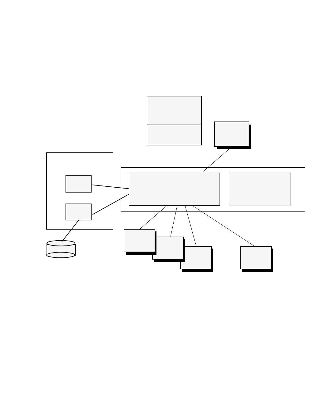
Figure 1-2 presents another view of the ZCOM Subsystem which
includes the relationships between the various components of the ZCOM
Subsystem:
Figure 1-2 ZCOM Subsystem Components
C Application
Program
ZCOM Subsystem
ZCOM Software Overview
ZCOM initialization
and Mux download
by ZMON
zmasterd
zmon
zmlog
Error log
Files
The ZCOM Subsystem is initialized by the zmon daemon which reads a
memory image file and downloads appropriate firmware to the ACC Mux
interface cards. The memory image file is created by running the ttgen
utility on an ASCII configuration file which contains information such as
what protocol will be used on the various ports of the ACC Mux cards,
and protocol specific configuration.
ZCOM I/F Library
ZCOM HP-UX Drivers
ACC I/F
Card
ACC I/F
Card
ACC I/F
Card
zterm
Utility
ZCOM Kernel
Tables & Buffers
...
ACC I/F
Card
Chapter 1 15
Page 16

ZCOM Subsystem
ZCOM Software Overview
The zmlog program is used to log error messages generated by the
programs and daemons of the ZCOM Subsystem. The zmasterd daemon
is used to facilitate starting up and shutting down the daemons in the
ZCOM Subsystem, and to automatically recover from daemon failures.
Application programs make calls to the routines in the ZCOM
application interface. The same requests that can be made
programmatically can also be made interactively by using the zterm
program
.
16 Chapter1
Page 17

ZCOM Subsystem
ZCOM Concepts
ZCOM Concepts
Throughout this manual, references are made to terminal ZLU or just
terminal. This does not mean a physical terminal device type but is a
generic term that can refer to any kind of physical or logical entity.
Examples of physical entities are printers, an HDLC link, terminals, etc.
Examples of logical entities might be an X.25 Permanent or Switched
Virtual Circuit.
In the ZCOM Subsystem, messages are sent directly from sender to
receiver (where the receiver is another program or a terminal ZLU).
They are routed using a pointer called a ‘ZLU’ which stands for ‘ZCOM
Logical Unit’. ZCOM uses t he ZLU for its addressing mechanism. A ZLU
may represent a terminal (for instance, an X.25 virtual circuit) or an
application program. Messages are sent to and received by ZLUs.
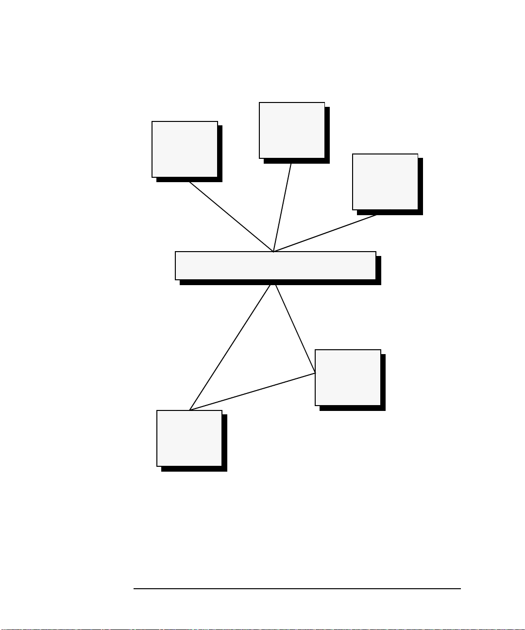
Figure 1-3 on page 18
shows a sample set of program and terminal ZLUs,
and their interaction with each other and a Mux card:
Chapter 1 17
Page 18
ZCOM Subsystem
ZCOM Concepts
Figure 1-3 Definition and Features of ZLUs
Terminal 2
Terminal 1
Terminal
ZLU=57
Program
ZLU=502
Application
Program A
Mux card
Terminal
ZLU=231
Program
ZLU=500
Application
Program B
Terminal 3
Terminal
ZLU=101
To communicate to another program or to a terminal, a program uses
ZCOM library calls to write to a program or terminal ZLU. Each program
ZLU points to a queue that contains all messages, including timeout and
statusmessages, that were deliveredto the program ZLU. These pointers
are maintained automatically by the ZCOM Subsystem. When a message
is sent to a ZLU, the data is moved to a system buffer first and the
address of the message is moved to the attached input queue.
18 Chapter1
Page 19

ZCOM Subsystem
ZCOM Concepts
Program ZLUs
Each program may open one or more program ZLUs which provides an
input message queue to that program. Think of a program’s input
message queue as a m ailbox where messages can be delivered. All
messages delivered are queued at the end of the input queue for a
program in the order in which they were received. Note that the message
is not actually delivered to the program, but simply placed into the input
queue. The program must issue a ZCOM library call to retrieve the
messages one-by-one from the input queue. The method used to cause a
message to be placed into a program’s input queue will be different
depending on whether the message was created by another program or a
physical/logical device.
If a message is sent (generated) by another program, then the sending
program must specify the ZLU of the program’s input queue to place the
message into. The receiving program need not do anything for the
message to be successfully delivered to their mail box (program input
queue).
However, when a message is generated by a terminal ZLU, any program
that wishes to receive messages from that device (terminal ZLU) must
inform the ZCOM Subsystem first. The program should issue a ZCOM
call (zset_rcvr) to tell the ZCOM Subsystem that all data coming from
the specified terminal ZLU should be delivered to its input queue.
Whenever data arrives from the device, it will be placed into the input
queues of all programs that have requested this data.
Terminal ZLUs
Terminal ZLUs represent a physical or logical device and do not have
input queues of their own. Any data coming from a terminal ZLU will be
delivered to the input queues of all applications that have requested it. If
there is no application interested in receiving the data, then the data is
thrown away and a message is logged to that effect.
TerminalZLUs do however have three different output (transmit)
queues. When a program sends data to a terminal ZLU,it can select one
of three queues to place that data on. Each queue represents a different
level of priority. The Express Queue is used for extremely high-priority
protocol dependent requests. The High-Priority Queue is used for high
priority data and the Low-Priority Queue is used for low priority data.
When a message is generated by an application, the buffers involved are
queued to the selected transmit queue and the ZCOM driver is notified.
Chapter 1 19
Page 20

ZCOM Subsystem
ZCOM Concepts
The driver is then responsible for handling the message. Messages on the
express q ueue are sent before those on the high priority queue which are
sent before those on the low priority queue.
Because the ZCOM Subsystem itself takes responsibility for the delivery
of messages, the sending program is able to specify a number of options
when it passes the message to the system. These options include:
• Continue execution whether the message is sent successfully or not.
• Continue execution but report any error status (status messages are
queued to the ZLU of the calling program).
• Continueexecution; a definite response will be queued to the program
ZLU when the send has completed.
• Suspend execution until the send has completed (i.e.,
acknowledgment that the message was transmitted).
On completion, the message buffer may also be passed back to the
sending application program if required.
Each message on the ZLU has a ‘type’ attribute so that the program
reading the ZLU is able to differentiate between status messages,
timeout messages and data messages from terminals or other programs.
20 Chapter1
Page 21

ZCOM Subsystem
User Interface
User Interface
The interface between the application programs and the ZCOM
Subsystem is through the ZCOM ‘C’ Application Programming Interface
(API) library. The functions provided by this library are documented in
Chapter 4 , “ZCOM C I/F Library Routines.” All functions within the
library are thread-safe and can be used in multi-threaded programs.
Both 32-bit and 64-bit applications are supported.
The interactive program ZTERM gives the user access to all the ZCOM
routines and can be used to test programs or terminals by sending and
receiving messages between them. The program ZSCAN allows the
programmer to display the contents of the ZCOM memory areas.
Chapter 1 21
Page 22

ZCOM Subsystem
References
References
The following manuals should be referred to when using the ZCOM
application interface:
• ACC Installation and Configuration Guide
• ACC Utilities Reference Guide
The manuals corresponding to the protocol being used should also be
referred to:
• ACC X.25 Protocol User’s Guide
• ACC HDLC/LAP-B Protocol User’s Guide
• ACC HDLC/LAP-D Protocol User’s Guide
• ACC HDLC/NRM Protocol User’s Guide
Documentation recommended for protocol developers includes:
• Z16C35 CMOS ISCC Technical Manual
(Zilog P/N DC-8286-01)
• Z80180/Z180 MPU Microprocessor Unit Tech Manual
(Zilog P/N DC-826-03)
• Z80 CPU TechnicalManual
(Zilog P/N DC-0029-04)
• SCC Technical Manual
(Zilog P/N DC-8293-01)
22 Chapter1
Page 23

2 ZCOM Message Handling
23
Page 24

ZCOM Message Handling
Overview
Overview
ZCOM message handling is achieved through logical constructs called
ZLUs which maintain queues for messages to terminals and programs.
The terminal ZLUs are either defined a t ZCOM configuration time using
ttgen, or can be created programmatically using the Dynamic System
Configuration functions; the program ZLUs are allocated dynamically
from a pool of ZLUs when requested.
24 Chapter2
Page 25

ZCOM Message Handling
ZLU Definition
ZLU Definition
There are three types of ZLUs. These are:
•Program
• Terminal (or remote device via a communication link)
•Mapped
Program ZLUs
A Program ZLU may be either a primary ZLU or an auxiliary ZLU. All
programs using ZCOM must have a primary ZLU defined. Other ZLUs
may then be defined as auxiliary if required. If a message is sent to
another program, then the destination ZLU is the other program’s
primary or auxiliary ZLU.
Terminal ZLUs
Terminal ZLUs are used to direct messages to terminals. Before a
program can receive messages from a terminal, a program must set itself
up as receiver for that particular terminal’s ZLU (using the zset_rcvr
routine call). Any number of programs can be set up as a receiver for a
given terminal at any one time. It is possible, of course, to set up a
program to route messages to other programs from the terminal ZL U.
NOTE Terminal ZLU is a generic term. The actual physical entity associated
with a terminal ZLU is dependent on the particular protocol being used.
For example, with a TTY protocol a Terminal ZLU would be associated
withaphysicalterminalorterminallikedevice.However,witha
protocol such as X.25, a terminal ZLU might represent a virtual circuit
or the HDLC line (X.25 level 2).
Chapter 2 25
Page 26

ZCOM Message Handling
ZLU Definition
Mapped ZLUs
AllmessagesaddressedtoaparticularZLUwillberedirectedtothe
alternate ZLU specified in the zmapr routine call if the original ZLU has
been mapped to a different ZLU. One use of mapped ZLUs is for
providing high availability systems. For example, if a hardware failure
was detected in one of the ACC Mux cards, the application could map all
of the ZLUs associated with the failed card to a spare unused card in the
system.
26 Chapter2
Page 27
ZCOM Message Handling
Message Queuing
Message Queuing
Each program ZLU (either primary or auxiliary) has a single input
queue on which messages are received and read on a first-in-first-out
basis.Because the ZLU is the input queuing mechanismfor timeoutsand
statuses,as well a s for data messages, all programs should request
(through the zopen routine) at least one program ZLU before using the
other ZCOM calls.
The ztimr routine may be used to enable or disable the timer on a
program ZLU. When enabled, a timeout message is added to the input
queue of the ZLU every n seconds (n being specified as a parameterto
the ztimr call). If there are already 10 or more messages on the queue, no
timer message is queued. Timer processing stops when ZTIMER and
ZCLOCK are reset to zero via the ztimr routine (a zero “time” value).
The application program uses the zread routinetoreadmessagesfrom
the input queue. All response and status messages are written to the
primary program ZLU. Data messages can be written to eit her the
primary or auxiliary program ZLUs.
When a zsend routine call is executed, the message to be sent is moved to
the ZCOM kernel buffer which is queued to the ZLU to which the
messagewassent.Themessageisaddedtotheendofthequeueforthe
specified ZLU.
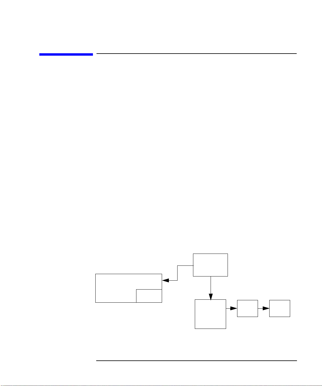
Figure 2-1 Program Message Queueing
Application A
zread
Chapter 2 27
Primary
Program
Input
Queue
Points to the
Input Queue
MSGMSG
Page 28

ZCOM Message Handling
Message Queuing
Queues for terminal ZLUs are located in the physical terminal tables in
the ZCOM memory area as shown in Figure 2-2. The physical terminal
tables (one per terminal) maintain four queues for each terminal.
Figure 2-2 Physical Terminal Table
Physical Terminal Table
Express Queue
High Priority Queue
Low Priority Queue
Unacknowledged Queue
The driver reads messages first from the express queue until there are
no remainingexpress queue messages, then from the high priorityqueue
until there are no high priority messages, at which stage the low priority
queue is read. Any further additions to the higher priority queues will be
read before the driver continues with the lower priority queues. When
the interface card is ready to accept messages, t he driver moves the
message to the unacknowledged queue and transfers the message to the
interface card (through the unacknowledged queue). Both the interface
card and the driver use DMA (Direct Memory Access) hardware to
transfer the messages. If the number of buffers on the unacknowledged
queue is less than the limit specified to TTGEN, more messages will be
transferred, otherwise the transfer will be suspended until some
outstanding messages are acknowledged.
Once the interface card has transmitted the message and has responded
with a definite status, the driver passes the status (if requested to do so)
back to the calling program. If the calling program also requires the
message buffer to be sent back with the status response, it is picked up
from the unacknowledged queue. Once the driver has passed the
message to the program, the message is removed from the
unacknowledged queue.
Messages in the unacknowledged queues for each terminal are also used
in a Mux restart: the messages are movedback to the high priority queue
to b e resent. The size of the unacknowledged queue is configurable in the
TTGEN configuration file.
28 Chapter2
Page 29

ZCOM Message Handling
Priorities
Priorities
Priorities only apply to messages that are destined for terminals.
MessagestoprogramZLUsaresimplyaddedtotheendoftheinput
queue for that ZLU.
Messages destined for terminal ZLUs may have either express, high or
low priority. The priority for a message is determined by bits
ZCOM_ZSEND_LPRand ZCOM_ZSEND_XPS of the mode parameter, in
the zsend and zcntl routine calls. If the ZCOM_ZSEND_XPS bit is set,
then the message is queued on the express queue in the physical
terminal table for that terminal ZLU. If the ZCOM_ZSEND_LPR bit is
set, then the message is queued on the low priority queue in the physical
terminal table for that terminal ZLU. If neither bit is set, then the
message is queued on the high priority queue. This enables background
tasks to be sent at lower priorities, without impacting any on-line
throughput.
The driver reads the information from the terminal tables, looking at the
high priority queue for each terminal and sending the message at the
head of that queue. The driver only checks the low priority queue if there
are no messages on the high priority queue. This means that any
message on the high priority queue will be sent first.
NOTE The Express Queue should be reserved for Protocol Control events, such
as, interrupts or resets. Normally, data should not be sent using the
Express Queue.
Chapter 2 29
Page 30

ZCOM Message Handling
Multiplexing
Multiplexing
The multiplexing feature of ZCOM allows more than one logical terminal
to be mapped to a single physical terminal. This mechanism i s
implemented in ZCOM by allowing messages to and from a terminal
ZLU to be intercepted by a program (which is able to alter the data
content, e.g., adding or removing headers) and then forwarded on to the
destination physical terminal or its receiver program.
Some fields in the logical terminal table and in the physical terminal
table are mentioned in the following descriptions; more information on
these fields can be found in the logical terminal table and the physical
terminal table information in the section on Tables and Data Structures.
The outbound and the inbound multiplexing are separate, so although in
most situations the multiplexing program will perform both functions, it
is possible to perform only inbound multiplexing or only outbound
multiplexing in any program.
The ltflag field of the logical terminal table (zltt_type) contains two flag
bits ZCOM_LTFLAG_OMX and ZCOM_LTFLAG_IMX, which indicate
whether messages to or from the logical terminal respectively, are to be
handled by a multiplexing program. These bits are set by TTGEN
according to the device type.
When more than one logical terminal is mapped to a single physical
terminal, the ltgzlk field (<zltt_type>.ltgzlk) linkage forms a circular list
of terminals in the same multiplexed group (i.e., mapped to the same
physical terminal). The ltqzlk field contains the ZLU number (16-bit) of
the next terminal in the group. For a non-multiplexing terminal, this
field contains the ZLU number of the current terminal (i.e., pointing
back to itself, a special case for circular list).
30 Chapter2
Page 31

ZCOM Message Handling
Multiplexing
Outbound Multiplexing
The multiplexing program uses the zread call to determine the origin of
the message, after which, the program would normally attach a protocol
header and forward the message to the destination physical terminal.
MZAUXL in the message header (see the chapter on Tables and Data
Structures) can be used to save the originating source node and ZLU on
the outbound message. The MZSRCE field in the message header is then
overridden with the multiplexing program’s primary ZLU, hence status
and response messages may be routed to the multiplexing program
insteadof the sender. Routine zsend writes to the physical terminal (with
bit ZCOM_ZSEND_NOMX set in the mode parameter). Routine zsend
with user header (mode bit ZCOM_ZSEND_MHD) must also be used.
The responses to the outbound messages are received by the
multiplexing program as type 6 (ZCOM_MSTYPE_RSLT) messages
(request code ZCOM_MRQCODE_WRITE [2]). The multiplexing
program has to strip the protocol header which it had previously added
and forward the response to the ZLU number saved in MSPARE (using
zsend with bits ZCOM_ZSEND_MHD and ZCOM_ZSEND_NOMX both
set).
Figure 2-3 Outbound Multiplexing
Logical Terminal #1
TZLU1
TZLU2
LTZMXP-PZLU
Logical Terminal #2
LTGZLK=TZLU2
Chapter 2 31
Physical
Terminal
PZLU
Page 32

ZCOM Message Handling
Multiplexing
If the ZCOM_LTFLAG_OMX bit is set in the LTFLAG word of the logical
terminal table, then a logical terminal is enabled for outbound
multiplexing. This means that any message sent (by zsend)tothis
terminal ZLU will be formatted as normal (type 4,
ZCOM_MSTYPE_LPLT, message with request descriptor block), but
instead of being queued to the physical terminal transmit queue, it will
be queued to the program ZLU defined by LTZMXP. These fields must
have been defined to the system for each terminal b y a prior zset_rcvr
call (mode 2, ZcOUTB_MLTPLX) by the outbound multiplexing program
during its initialization.
The zcntl call works in a similar way to zsend. For example, an enable of
a multiplexed logical terminal ZLU will queue an enable request (type 4,
ZCOM_MSTYPE_LPLT, request code 7, ZCOM_MRQCODE_ENB) to the
outbound multiplexing program’s input queue. These messages would
normally be used to maintain the flags for the logical terminal in
LTSTAT. They may also generate a control command to the physical
terminal from the multiplexing program.
Inbound Multiplexing
If the ZCOM_LTFLAG_IMX bit is set in the LTFLAG word of the logical
terminal table, then the logical terminal is enabled for inbound
multiplexing. This means that when an application program selects the
terminal for input (using zset_rcvr default mode 0), zset_rcvr will
insert the application program’s ZLU into LTZRVR (rather than
PTZRVR for a t erminal without inbound multiplexing).
It is up to the inbound multiplexing program to define itself to the ZCOM
subsystem as the receiver for messages from the physical terminal using
the zset_rcvr (mode 1, ZcINB_MLTPLX) call. This sets PTZRVR in the
physical terminal table.
The inbound multiplexing program has the task of receiving a ll
messages from the physical terminal. It determines the origin of the
logical terminal from which the messages were sent. Then it processes
any of the control messages and forwards the data portion of any data
messages to the application receiver.
32 Chapter2
Page 33

Figure 2-4 Inbound Multoplexing
ZCOM Message Handling
Multiplexing
TZLU
APPLICATION
Physical
Ter minal
Logical
PTZLU
Terminal
LTZRVR
PTZRVR=PZLU
PZLU
Thus, to process an inbound message with multiplexing:
• zread (themessagetypewillbetype1,ZCOM_MSTYPE_MSLT-a
message from a terminal ZLU).
• The source ZLU is obtained from PTZLU. PTZLU gives the ZLU of
one of the ZLUs in a multiplexed group.
• Decode the protocol header to extract the logical terminal address.
Use the ltfind routine to scan the multiplexed group to find a match of
the logical terminal address with LTADDR.
• Build a ZCOM message header where the source ZLU is the ZLU
found by ltfind, and the destination ZLU is taken from LTZRVR of the
logicalterminalable.
•Usezsend (with bit ZCOM_ZSEND_MHD set) to send the message
and the ZCOM header to LTZRVR.
Chapter 2 33
Page 34

ZCOM Message Handling
Terminal State
Terminal State
Within the ZCOM subsystem, the terminal state may be either enabled
or disabled, activated or deactivated. For normal I/O operations, a
terminal ZLU must be both enabled and activated. If a terminal is
disabled (regardless of whether it is activated), then no messages can be
sent to it or received from it.
If a terminal is enabled but deactivated, then messages can be sent to
the terminal, but none can be received. The following table illustrates
the different combinations.
Terminal State SEND RECV
Enabled/Activated Yes Yes
Enabled/Deactivated Yes No
Disabled/Activated No No
Disabled/Deactivated No No
NOTE A terminal state of disabled overrides the activated/deactivated status.
For some protocols (such as the NCR 301 protocol), the protocol handler
automatically deactivates the terminal when a valid message is received
and until it has been processed. Each time a message is received, the
terminal must be reactivated by the receiving program, using the zcntl
command with the ‘activate’ request code ( request code 9,
ZCOM_MRQCODE_ACT).
34 Chapter2
Page 35

ZCOM Message Handling
Error Handling
Error Handling
In the normal functioning of ZCOM, transmission errors on messages to
terminal ZLUs are handled by the Mux interface card firmware. The
firmware always sends a status back to the driver after it has processed
a request - retries are handled internally . The driver checks the mode of
the send (i. e., send no wait, report errors, etc.) to determine what to pass
back to the requesting program.
If a power failure occurs or the Mux interface card crashes, the driver
receives an interrupt from the operating system. This interrupt causes
thedrivertosendarequesttoZMONtodownloadthefirmwaretothe
particular interface card and to perform a full restart sequence (which
also involves re-sending any unacknowledged messages). If the directory
/var/opt/acc/dmp exists, ZCOM will upload the contents of the Mux
card memory and store it in a file in this directory whenever a Mux card
failure is detected. This provides the ability to analyze firmware failures
which can be particularly valuable during the development of custom
protocols.
For a detailed description of ZCOM C interface routine error codes,
please refer to the ACC Error Guide.
Chapter 2 35
Page 36

ZCOM Message Handling
Error Handling
36 Chapter2
Page 37

3ZCOMTablesandData
Structures
37
Page 38

ZCOM Tables and Data Structures
Introduction
Introduction
This chapter gives a detailed description of the ZCOM subsystem
memory organization and table layout.Each table structures is described
in overview, followed by a detailed explanation of all of the elements
within the table.
38 Chapter3
Page 39

Memory Organization
The ZCOM Logical Device Manager (LDM driver) reserves a contiguous
block of kernel memory for tables for its use. The maximum size of this
memory block is tunable at kernel build time through the
zcom_mem_size parameter in the “system” file used to build your
kernel. T he default value for this parameter is 4 Mbytes. This memory is
allocated relative to a starting pointer. The memory is organized by
function into the following groups:
Figure 3-1 Memory Organization
ZCOM Header Structure
Node Table Entries
ZLU Tables
Logical Terminal Tables
Physical Terminal Tables
ZCOM Tables and Data Structures
Memory Organization
Interface Tables
Response Records
Queue Header Structures
ZCOM Data Buffers
The TTGEN configuration file describes the sizes and initial content of
these tables. When TTGEN is run, it produces a memory image file that
isthesamesizeandinthesameformatasthismemorylayout.The
memory image file is loaded into the kernel memory by ZMON via the
LDM when the system is initialized. Most of the tables are preset up in
the file by TTGEN; however, the response headers, queue headers and
data buffers are created and initialized by the LDM.
Note that TTGEN reports the size of the memory block in the “System
Information” section of the listing (if a listing is requested). If the
tunableparameter zcom_mem_size is different from the reported size of
the memory block, the ‘ZCOM Data Buffers’ area will be increased or
reduced to fit the memory block in the kernel memory during ZCOM
subsystem startup.
Chapter 3 39
Page 40

ZCOM Tables and Data Structures
Differences in 32-bit and 64-bit Data Structures
Differences in 32-bit and 64-bit Data
Structures
HP-UX supports 64-bit mode using the LP64 model. This means the long
and pointer fields are 64-bits in length. The ZCOM memory data
structures are designed to be 32/64-bit neutral by using conditional
padding fields. For example, a pointer field is defined as a 64-bit pointer
in 64-bit mode. But when the same field is used in the 32-bit kernel, it is
a 32-bit pointer prefixed with a 32-bit padding field (the padding is
inserted in front of the field). The data structures hence are the same
sizes in both 32 and 64-bit modes. This gives better control over data
alignment in the data structures, and allows 32-bit utilities to
manipulate both the 32and 64-bit data structures easily.
But this still does not give full transparency to 32-bit programs that
access ZCOM kernel tables on a 64-bit system. When a 32-bit program
manipulates a 64-bit long or pointer field in a data structure, the
program should consider whether the data structure comes from a 32-bit
or 64-bit kernel, even though it has the same size and layout. The
program should treat the padding fields as hidden fields (same as the
data structure alignment gaps inserted by the compiler) and should not
reference them directly.
Another side-effect is the ‘shifting’ of the long or pointer fields. Although
the overall layout is the same, the location offset of a long or pointer field
within a data structure is different in 32-bit and 64-bit modes. When
used in 32-bit mode, due to the presence of the 32-bit padding, the
position of a long or pointer field will be shifted 4-bytes towards the end,
compared to the same field when used in 64-bit mode.
Some of the data fields are of fixed 64-bit (e.g. hssoff in zheader_type)in
both 32/64 modes. If a 32-bit program is to manipulate these 64-bit fields,
it is recommended that the program should be compiled with the option
-Ae (extended ANSI) or -Ac (K&RCmode),soastoenablethe‘long long’
type for 64-bit integer.
The following sections describe the ZCOM data structures in 64-bit
mode. Hence the conditional padding fields are suppressed. If they are
used in a 32-bit environment, the long and pointer fields will become
32-bit, and the 32-bit padding will be present.
40 Chapter3
Page 41

NOTE
ZCOM Tables and Data Structures
Differences in 32-bit and 64-bit Data Structures
The following sections document the data structures used internally by
the ACC ZCOM product to implement its functionality. These data
structures are subject to change without notice. Programs that directly
use these structures may be required to recompile their sources when a
new version of t he ZCOM subsystem is released (this will be indicated in
the release notes).
Chapter 3 41
Page 42

ZCOM Tables and Data Structures
ZCOM Header Structure
ZCOM Header Structure
The ZCOM Header structure holds the system parameters and pointers
to other areas of the ZCOM memory tables as well as other information
that pertains to the whole ZCOM subsystem. The layout o f the ZCOM
Header structure zheader_type isshowninTable3-1.
T able 3-1 ZCOM Header Structure
Field Name Field Description Field Type Size
HLABEL Header label char [4] 4
HZREVC ZCOM rev code uns.short 2
HTREVC TTGEN rev code uns.short 2
HNAME1 Name of TTGEN source file char [256] 256
HNAME2 Name of TTGEN object file char [256] 256
HSNAME System name (79 characters max) char [80] 80
HSSOFF System starting offset uns.longlong 8
HSSSIZE Total system size in bytes uns.int 4
HBPSIZE Buffer pool size in bytes uns.int 4
HNDMAX Total number of node table entries uns.short 2
HZLMAX Total number of ZLUs uns.short 2
HTMZLU Number of terminal ZLUs uns.short 2
HSPZLU Number of program ZLUs uns.short 2
HSPZL1 First program ZLU number uns.short 2
HLTDSZE Size of LTDATA in LT Table uns.short 2
HLTMAX Number of logical terminal tables uns.short 2
HPTMAX Number of physical terminal t ables uns.short 2
HNCARD Number of interface tables uns.short 2
HNRESP Number of response records uns.short 2
HNLTQL Number of LTT queue labels uns.short 2
HNLTSL Number of LTT storage labels uns.short 2
HPNTBL Pointer to 1st Node table entry pointer 8
(Bytes)
42 Chapter3
Page 43

ZCOM Tables and Data Structures
ZCOM Header Structure
T able 3-1 ZCOM Header Structure
Field Name Field Description Field Type Size
HPZLU Pointer to 1st Zlu table pointer 8
HPTTBL Pointer to 1st Logical terminal table pointer 8
HPPTBL Pointer to 1st Physical terminal table pointer 8
HPIFTP Pointer to 1st Interface table pointer
HPRESP Pointer to 1st response record pointer 8
HPQUES Pointer to 1st Queue header pointer 8
HPBFFR Pointer to data buffer pool pointer 8
HPQLIM Default program queue limit (msgs) uns.int 4
HUNACK Default terminal unack limit (bytes) uns.int 4
HMAXTX Default pending TX limit (messages) uns.int 4
HIPLIM Default IFT port TX limit (msgs) uns.int 4
HCTOTAL Total number of DSC requests uns.int 4
HCSTATE DSC state
short 2
(Bytes)
If positive, it is the number of active DSC
requests. If negative, DSC feature is suspended.
HCSWAIT NumberofDSCstatewaiters uns.short 2
HRDATAQ Remote data queue header zqhd_type 56
HNDPID ZNODE Process ID int 4
HNDSIG ZNODE required s ignal int 4
HNIDLE ZNODE idle timer value uns.int 4
HNHIGH ZNODE queue high-water mark uns.int 4
HNLOW ZNODE queue low-water mark uns.int 4
HNWAIT ZNODE high-water mark waiter uns.short 2
HLCLND Local node number uns.short 2
HLTQTB Queue label entries (16 bytes each) struct [20] 20*16
HLTSTB Storage label entries (16 bytes each) struct[20] 20*16
DSC_ercvrs Dyn. Reconfig. SEM receivers pointer 8
ETPLIM Default E1/T1 port transmit limit uns.int 4
HOSTYPE Type of operating system int 4
Chapter 3 43
Page 44

ZCOM Tables and Data Structures
ZCOM Header Structure
HLABEL - ZMON identifier label
The identifier label contains the word ‘ZMON’ and provides compatibility
with HP1000 version of ZCOM. The memory image file contains the word
‘TTGE’ in this position. The LDM overwrites this after the ZCOM
subsystem has been initialized.
HZREVC - ZCOM revision code
TTGEN initializes this field with a 16-bit revision code, indicating the
version of the table structures. This revision code is stored as four 4-bit
digits. The first two digits represent the revision of a major release and
the last two digits represent a minor release revision. Data structures
and applications linked with a previous revision of the ZCOM software
will be compatible if they have same major revision code. ZMON checks
whether the revision code is acceptable. The different minor numbers
indicate compatible revisions, such as bug fixes (as long as the major
release revision code is the same).
HTREVC - TTGEN revision code
TTGEN inserts its integer revision code in this field in the memory
image file. It is loaded into memory (unchanged) by ZMON and the LDM.
This 16-bit revision code is stored in the same format as the ZCOM
revision code (HZREVC). However, there is no validation of this field.
HNAME1 -NameoftheTTGENsourcefile
Full path name of the source file used by TTGEN to generate the object
file. This field is limited to 256 bytes and is null terminated.
HNAME2 -NameofTTGENobjectfile
Full path name of the TTGEN produced object file which was then used
to startup (initialize) the ZCOM subsystem. This field is limited to 256
bytes and is null terminated.
HSNAME - ZCOM subsystem runtime instance name
Contains the contents of t he System-Name parameter supplied in the
TTGEN configuration file. This field is limited to 80 bytes and is null
terminated.
44 Chapter3
Page 45

ZCOM Tables and Data Structures
ZCOM Header Structure
HSSOFF - System starting offset
This pointer contains the starting physical kernel memory address of the
ZCOM subsystem memory. It is initialized to zero by TTGEN. ZMON
initializes it with the memory address while loading the memory tables
into kernel memory. It is a 64-bit value when used in a 64-bit kernel.
HSSIZE - Total runtime system size in bytes
This is the total size in bytes of the ZCOM subsystem memory, including
all tables, queue headers, and the buffer pool.
HBPSIZE - Buffer pool size in bytes
This is the size in bytes of the ZCOM buffer pool. It is defined by the
Buffer-Pool parameter in the TTGEN configuration file.
HNDMAX -Numberofnodeentries
This contains the maximum number of node entries which may exist in
the node entries memory section. This value is defined by the Node-Entry
keyword in the TTGEN configuration file. Each Local-Node and
Remote-Node definition consumes one node table entry.
HZLMAX - Total number of ZLUs
Total number of terminal ZLUs and spare (i.e.,program) ZLUs. That is,
this is the combined values of the Program-ZLU and Terminal-ZLU
parameters specified in the TTGEN configuration file.
HTMZLU -NumberofterminalZLUs
This is the number of ZLUs out of the total (HZLMAX) that are allocated
to terminals. The terminal ZLU numbers are allocated from 1 up to the
number specified in this field. The TTGEN Terminal-ZLU parameter is
used to initialize this field.
HSPZLU -NumberofprogramZLUs
Total number of available program ZLUs. The TTGEN Program-ZLU
parameter is used to initialize this field.
HSPZL1 - First program ZLU number
Number of the first ZLU not allocated to terminal ZLUs. This field is
initialized to the value of the TTGEN parameter Terminal-ZLU +1.It
indicates where the program ZLUs begin within the ZLU Table. Note
that program ZLUs are assigned from the range (Terminal-ZLU+1) to
(Terminal-ZLU + Program-ZLU).
Chapter 3 45
Page 46

ZCOM Tables and Data Structures
ZCOM Header Structure
HLTDSZE - Logical terminal table LDATA buffer size
This specifies the size of the LDATA buffer in the logical terminal tables.
This value is initialized from the Logical-Size parameter in the TTGEN
configuration file. Set this parameter to 212 for backward compatibility
with HP 1000 programs (so that the total size of Logical Terminal Table
with extension is 512 bytes).
HLTMAX - Number of logical terminal tables
Contains the maximum number of Logical Terminal Tables (LTT) which
may exist in the configuration. This value is initialized from the
Logical-Term parameter in the TTGEN configuration file.
HPTMAX -Numberofphysicalterminaltables
Contains the maximum number of Physical Terminal Tables (PTT)
which may exist in the configuration. This value is initialized from the
Physical-Term parameter in the TTGEN configuration file.
HNCARD - Number of Mux interface tables
Number of Interface Tables (IFTs) which may exist in the configuration.
This value is initialized from the Interface-Table parameter in the
TTGEN configuration file. Note that there is one Interface Table (IFT)
per Mux card defined.
HNRESP -Numberofresponserecords
This field contains the number of response records in the ZCOM
subsystem. This value is initialized from the Program-ZLUparameter in
the TTGEN configuration file.
HNLTQL - Number of LTT queue labels
Numberof entries in the queue label table,up to a maximum valueof 20.
It is initialized by TTGEN to the number of Logical-Data statements
defined in the TTGEN configuration file. This value can be modified by
calling the zltqueue() routine.
HNLTSL - Number of LTT storage labels
Number of entries in the storage label table, up to a maximum value of
20. It is initially set up by TTGEN and subsequently maintained by the
LDM.
HPNTBL - Node Table pointer (znode_type *)
This is a pointer to the first entry in the Node Table. Note that all of the
node entries are stored in sequential order within kernel memory.
46 Chapter3
Page 47

ZCOM Tables and Data Structures
ZCOM Header Structure
HPZLU -ZLUtablepointer(zlu_type*)
This is a pointer to the 1st entry in the ZLU table. Note that all of the
ZLU table entries are stored in sequential order within kernel memory.
HPTTBL - Logical Terminal Table pointer (zltt_type *)
This is a pointer to the 1st Logical Terminal table. Note that all of the
LTTs are stored in sequential order within kernel memory.
HPPTBL - Physical TerminalTable pointer (zptt_type *)
This is a pointer to the 1st physical terminal table. Note that all of the
PTTs are stored in sequential order within kernel memory.
HPIFTP - Interface Table pointer (zift_type *)
This is a pointer to the first Interface Table (IFT). Note that all of the
IFTs are stored in sequential order within kernel memory.
HPRESP - Pointer to the first response record (zrsp_type *)
This is a pointer to the first response record. Note t hat all of the response
records are stored in sequential order within kernel memory.
HPQUES - Queue Header pointer (zqhd_type *)
This is a pointer to the first Queue Header. Note that all of the Queue
Headers are stored in sequential order within kernel memory.
HPBFFR - Data buffer pointer (char *)
This is a pointer to the start of the data buffer pool. The data buffer pool
is a block of contiguous kernel memory used for dynamically allocating
data buffers for a variety of uses. The size of this block of memory is
determinedby the Buffer-Pool parameter from the TTGEN configuration
file.
HPQLIM - Default program ZLU message queue limit
The default program ZLU message queue limit is the maximum number
of messages that may be queued on each program ZLU. This value is
initialized from the Queue-Limit parameter in the TTGEN configuration
file. The default limit may be overridden during a zopen() by specifying a
non-zero value in the limit parameter. The program ZLU queue limit
maybechangeddynamicallybycallingthezsetql() routine.
Chapter 3 47
Page 48

ZCOM Tables and Data Structures
ZCOM Header Structure
HUNACK - Maximum number of unacknowledged Tx buffers pending
onaterminalZLU
Upper limit of the total size (in bytes) of all unacknowledged transmit
messages to a terminal ZLU. If this limit has been reached, any further
write requests to the terminal ZLU will be queued up in the terminal
table, but will not processed by the driver immediately. The driver will
resume processing of queued transmit requests when the Mux card
acknowledges the completion of a previously issued transmit request for
this terminal ZLU.This mechanism is used to prevent a few (or only one)
terminal from consuming all of the transmit buffers on the Mux interface
card. This field is initialized from the Unack-Limit parameter in the
TTGEN configuration file. The unacknowledged queue limit may be
changed dynamically by calling the zsetql() routine.
HMAXTX - Maximum number of Tx buffers pending on a terminal ZLU
Limit of transmit buffers pending on a terminal. When this limit is
reached, the program doing write requests to the terminal will be
suspended until some of the pending transmit requests are sent.
Together with the limit imposed by HUNACK, this protects the ZCOM
system buffers from excessive usage due to dead terminals (or other kind
of device).
HIPLIM - Default IFT port TX limit (bytes)
This field contains the limit (in bytes) of all unacknowledged transmit
messages t o terminal ZLUs belonging to the same port of a 2/8-port Mux
card. Each port on the card has approximately 24,480 bytes of buffer
space available for both internal use and transmit requests. If the DAM
issues a transmit request to the Mux card and the Mux card does not
have enough free buffers to hold the request data, the Mux will reject the
requestwithan“out of buffers” error. The DAM will retry the request
after an unacknowledged transmit request completes. This field is used
to minimize the number of retries (and thereby increase overall
performance) by imposing a limit on the size of unacknowledged
transmit requests. This value is configured through the Port-Limit
parameter in the TTGEN configuration file and is used t o initialize the
individual port limits iplimit[] kept in the interface table (zift_type).
48 Chapter3
Page 49

ZCOM Tables and Data Structures
ZCOM Header Structure
HCTOTAL - Total number of Dynamic System Configuration (DSC)
requests
This field contains the number of DSC requests processed by the ZCOM
subsystem since it was initialized and started up. It is incremented every
time a DSC request is processed. This value is for information purposes
only.
HCSTATE - Dynamic System Configuration (DSC) State
This field is used by the ZCOM subsystem as an indicator for controlling
DSC functions.When the value is zero or positive, the DS C functions are
enabled.The value represents the number of active DSC requests. When
the value is negative, DSC functions are disabled. DSC requests are
rejected until this field is set to zero. This field is initialized to zero by
TTGEN.
HCSWAIT -NumberofDSCstatewaiters
This field contains the number of processes suspended, waiting for the
DSC state to be set to zero. That is, the processes are waiting for the DSC
functions to be enabled. A process will be suspended if it issues a DSC
request while the DSC functions are disabled or if it issues a DSC disable
request while other DSC requests are in progress.
HRDATAQ - Remote data queue (ZNODE Queue)
This is t he data queue for remote ZCOM requests. All ZCOM API
requests to a remote node or deferred remote request responses will be
added to this queue by the LDM. The remote node request daemon,
ZNODE, reads and processes the request from this queue. This special
queue is sometimes referred to as the ZNODE queue or ZNODE data
queue.
HNDPID - ZNODE HP-UX process ID (PID)
This field contains the process ID (PID) of the local ZNODE daemon to
use for signalling the arrival of data on the ZNODE queue. If this value
is positive, the LDM will send a signal to this process ID whenever new
data is placed in the queue. If this value is negative, a signal will be sent
to the process group. The group ID used is the absolute value of this field.
This field is initialized to zero by TTGEN and is set up by the ZNODE
program when it starts up.
Chapter 3 49
Page 50

ZCOM Tables and Data Structures
ZCOM Header Structure
HNDSIG - ZNODE signal number
ContainsthetypeofsignaltousewheninformingZNODEofthearrival
of new data in the ZNODE queue. This field is initialized to zero by
TTGEN and is set up by the ZNODE program when it starts up.
HNIDLE - ZNODE idle timer
This contains the time in seconds since ZNODE last issued a
Node-Status Update ioctl request to the ZCOM subsystem (LDM). The
LDM timer increments this field once every second and marks all nodes
as DOWN when it exceeds the inacti vity period (currently 20 seconds).
This field is initialized to zero when the ZCOM runtime subsystem is
started up.
HNHIGH, HNLOW - ZNODE queue high and low water marks (flow
control)
ThesetwofieldsareusedbytheLDMtocontroltheflowofdatabetween
the ZNODE daemon and t he LDM. When the number of pending
messages on the ZNODE queue reaches the high-water mark, programs
initiating remote requests a re suspended to avoid excessive buffer usage.
Suspended programs will be allowed to resume execution when the
number of queued messages drops to or below the low-water mark.
A special cas e exists when both the high and low water marks are set to
the same value. In this situation, whenever the number of pending
messages on the ZNODE queue is at or above this mark, all remote
requestsarerejectedwithanimmediateerrorreturnvalueofZENBUSY
(-1, ZNODE is busy).
Note that this mechanism is only applicable to programs initiating
remote requests and does not limit the messages or responses generated
as a result of ZCOM subsystem operation (e.g. a terminal ZLU returns a
message to its receiver in a remote system).
ThesetwovaluesaredefinedbytheFlow-Controlkeywordinthe
TTGEN configuration file. If not specified, they will default to a
high-water mark value of the maximum queue limit and a low-water
markvalueofzero(i.e.themechanismisdisabled).
HNWAIT - ZNODE queue high-water mark waiter
This field is maintained and used by the LDM to keep track of the
number of programs currently suspended due to the high/low water
mark flow control mechanism. It is initialized to zero by TTGEN.
50 Chapter3
Page 51

ZCOM Tables and Data Structures
ZCOM Header Structure
HLCLND - Local node number
The node number of the local ZCOM subsystem. If the Node-Definition
section in the TTGEN configuration file is omitted, TTGEN defaults this
field to one (1). Otherwise, it is initialized to the value of the Local-Node
parameter. It is set up by TTGEN as the first node table entry that has
zero ZLU number. There may be other numbers that also refer to the
local node but HLCLND is the only one that is used to identify the local
node on outbound messages.
HLTQTB - Queue label table
Each entry in the queue label table indicates the ownership of a data
queue in a logical terminal table. Each entry has a structure of 16 bytes
(zqlb_type)asshowninTable3-2.
Table3-2 QueueLabelTable
Field Name Field Description Field Type Size
QLBGRP Appl. grp. number (0 = globally assigned) uns.short 2
QLBNAM Queue label name char 8
QLBQNB Allocated queue number uns.short 2
QLBRSV <reserved>, unused char 4
(bytes)
The table is initialized by TTGEN from the Logical-Data statements in
the TTGEN configuration file. There is one entry in the Queue label table
for each Logical-Data statement. Additional entries can be added to this
table by calling the zltqueue routine (up t o a maximum of 20 queue
labels).
Chapter 3 51
Page 52

ZCOM Tables and Data Structures
ZCOM Header Structure
HLTSTB - Storage label table
The storage label entry indicates the ownership of an application data
storage area in the logical terminal table extension area. Each entry is a
structure of 16 bytes (zslb_type), as shown in Table 3-3.
Table 3-3 Storage Label Table
Field Name Field Description Field Type Size
SLBGRP Appl. grp. number (0 = globally assigned) uns.short 2
SLBNAM Storage label name char 8
SLBSZE Size of the application data in bytes uns.short 2
SLBOFF Offset from the start of the LTT to the application data
in the extension area. Therefore, this value is the size
of the LTT plus the offset of the application data from
the start of the LTT extension area.
SLBRSV <reserved>, unused char 2
The table is initialized by TTGEN from the Logical-Data statements in
the TTGEN configuration file. There is one entry in the Storage label
table for each Logical-Datastatement. Additional entries can be added to
this table by calling the zltqueue() routine (up to a maximum of 20
storage labels).
short 2
(Bytes)
DSC_ercvrs - Dynamic Reconfiguration System Event Receivers pointer
(zshaddr_type *)
This field contains a pointer to a linked list of all applications that wish
to be notified whenever a ZCOM subsystem dynamic reconfiguration
system event message is generated (through the zconfig routine). This
field is initialized by TTGEN to zero. It will only contain a value if at
least one application has requested notification.
52 Chapter3
Page 53

ZCOM Tables and Data Structures
ZCOM Header Structure
ETPLIM- Default E1/T1 IFT port TX limit (bytes)
This field contains the limit (in bytes) of all unacknowledged transmit
messagesto terminal ZLUs belongingto the sameport and subchannel of
an E1/T1 card. Each E1/T1 card has approximately 16 M-bytes of buffer
space available for both internal use and transmit requests. If the DAM
issues a transmit request to the E1/T1 card and the card does not have
enough free buffers to hold the request d ata, the Mux will reject the
requestwithan“out of buffers” error. The DAM will retry the request
after an unacknowledged transmit request completes. This field is used
to minimize the number of retries (and thereby increase overall
performance) by imposing a limit on the size of unacknowledged
transmit requests. This value is configured through the E1T1-Port-Limit
parameter in the TTGEN configuration file and is used to initialize the
individual port and subchannel limit array iplimit[] kept in the interface
table (zift_type).
HOSTYPE -Typeofoperatingsystem
This field indicates the type of operating system that manipulates the
data structures. The allowed valuesare 0, 32 (32-bit kernel) or 64 (64-bit
kernel). It is first set up by TTGEN to 0. Then it is set to 32 or 64 by
ZMON when it initializes the ZCOM kernel memory block.
Chapter 3 53
Page 54

ZCOM Tables and Data Structures
Node Entries Table
Node Entries Table
TheNodeEntriestablecontainsinformationabouttheremoteZCOM
systems that communicate with the local ZCOM subsystem. Each
Local-Node and Remote-Node definition in the TTGEN configuration file
occupy one entry in the table. Each entry structure is 392 bytes long and
has the format shown in Table 3-4.
Table 3-4 Node Entries Table
Field Name Field Description Field Type Size
node_num ZCOM system node number uns.short 2
timeout Default timeout value for this node uns.short 2
flags Node status and internal flags uns.int 4
stats Statistics for this node struct 16
ndshzrvrs List of node status event receivers pointer 8
nhost Number of hosts in the host array uns.short 2
spare1 Reserved, not used uns.short 2
spare2 Reserved, not used int 4
host Host link information struct [4] 4*88
(Bytes)
NODE_NUM - Node number
This field contains a unique node number that identifies the entry.
TIMEOUT - Default timeout value for this node
This field contains timeout in seconds for requests sent to this remote
node. Most remote ZCOM requests (e.g. ZOPEN, ZTIMR,etc)requirea
definite response from the remote ZCOM subsystem. If the response is
not received within the timeout period specified by this field, error
ZENTOUT (-23) is returned to the application program. This field is
initialized by TTGEN with the timeout value specified in a Remote-Node
definition. This field is zero for a local node entry.
54 Chapter3
Page 55

ZCOM Tables and Data Structures
Node Entries Table
FLAGS - Node status and internal flags
This bit-field structure contains bits to maintain state and other internal
information about this node. The contents of this field are as follows:
FLAGS.event - Set to 1 if there is at least one application that wants to be
notified of a status change for the node.
FLAGS.valid - Set to 1 if this node entry in the table is valid; that is,
currently defined and in use.
FLAGS.status - Set to 1 if this node is currently UP. The status bit indicates
whether a remote node is usable. If this bit is not set, the
LDM will reject all requests to that node with a
ZENDOWN(-61)error.Foralocalnode,thestatus bit
indicates that the ZNODE daemon is running properly.
FLAGS.local- Set to 1 if this node entry in the table represents the local
node.
STATS - Statistics for this node
This field is a data structure that contains some statistics on the data
traffic for this node. The layout of this structure is shown in Table 3-5.
Table 3-5 STATS Data Structure
Field Name Field Description Field Type Size
icount Number of incoming messages uns.int 4
ibytes Number of incoming bytes uns.int 4
ocount Number of outgoing messages uns.int 4
obytes Number of outgoing bytes uns.int 4
NDSHZRVRS - Pointer to a list of receivers for node status events.
This field contains a pointer to a linked list of applications to be notified
whenever this node changes state. Whenever this node changes state
from up-to-down or down-to-up, a node status system event message will
be sent to each program in this linked list. That is, those applications
that have issued a zevent_rcvr() call to receive node status events. This
field will be set to zero if there are no applications to be notified.
Chapter 3 55
(Bytes)
Page 56

ZCOM Tables and Data Structures
Node Entries Table
NHOST - The number of defined hosts in the host array.
This field contains the number of host link records defined in the HOST
table below .This field is zero for a local node entry.
HOST - Host link information structure (array)
This array of structurescontains informationabout eachof the host links
for this node. It can hold information on up to four host links. Each
element of the array contains the fields for one host link as shown in
Table 3-6.
Table 3-6 Host Link Information Structure
Field Name Field Description Field Type Size
linkname Host name or IP address for this link char [64] 64
stats Statistics for this link struct 16
flags Node status and flags uns.int 4
spare3 Reserved, not used int 4
(Bytes)
LINKNAME - The name of the remote system
This field contains the host name or the IP a ddress to be used in
accessing the remote node via TCP/IP. If a host name is specified, it must
be defined in the /etc/hosts file.
STATS - Statistics for this host link
This field is a data structure that contains some statistics on the data
traffic for this link. The layout of this structure is identical to that shown
above. T he data in this structure is maintained by the ZNODE daemon.
FLAGS - Host link status and flags
This bit-field data structure contains information on the status of a link.
It is identical to the flags structure documented above. However only the
status and valid b its are currently used. The status bit indicates whether
this link is currently up or not. If the link is down (status =0),the
ZNODE daemon will route remote requests on any secondary links that
areup.ThedatainthisstructureismaintainedbytheZNODEdaemon.
56 Chapter3
Page 57

ZCOM Tables and Data Structures
ZLU Tables
The ZCOM logical unit table relates a terminal device or a program
queue with a number or logical unit. The ZCOM logical units are called
ZLUs to distinguish them from the HP-UX logical units (LUs).
Each ZLU entry structure contains 40 bytes of data.
The ZLU table is split into two logically distinct parts. The first part is
the physical terminal area, and the second the dynamically assignable
program ZLUs. The latter are used for program input queues. The ZLUs
can be mapped so that a particular ZLU can point to any other ZLU.
Individual ZLU Entries
The individual ZLU data structure (zlu_type) layout is shown in Table
3-7.
Table 3-7 Individual ZLU Data Structure (zlu_type)
ZLU Tables
Field Name Field Description Field Type Size
(Bytes)
zcksum ZLU checksum uns.short 2
zlttype ZLU type uns.short 2
zpoint ZLU pointer or mapped node nmbr uns.short 2
zmpzlu Mapped ZLU number uns.short 2
zmpzcs Mapped ZLU checksum uns.short 2
zlname ZLU Name (8 bytes) char [8] 8
zowner PID number of owner uns.short 2
ztimer Timeout interval (seconds) short 2
zclock Timeout clock short 2
zlock ZLU lock pointer pointer 8
refcnt Lock reference count unns.int 4
spare1 Reserved, not used int 4
Chapter 3 57
Page 58

ZCOM Tables and Data Structures
ZLU Tables
ZCKSUM -ZLUchecksum
The checksum is used as an integrity check to ensure that a ZLU has not
been altered while it is active. It is the 16-bit binary sum of bytes 3 to 18
of the ZLU entry (with any overflow discarded). It is calculated when the
ZLU table entry is created.
ZLTYPE -TypeofZLU
TheZLUtypevaluesareshowninTable3-8.Thetypevalueisalsoused
to indicate whether the ZLU is defined.
Table3-8 ZLUTypeValues
Type Description
0 ZLU is not defined
1 ZLU is local terminal (ZPOINT is a logical terminal number *)
2 ZLU is a local program (ZPOINT is a queue number)
3 ZLU is mapped (ZPOINT is a mapped ZLU node number)
* The logical terminal number is allocated by TTGEN from the TTGEN
configuration file.
ZPOINT - ZLU pointer or mapped node number
The field is used to link the ZLU with the entity it represents. The
meaning of the field is given in the table under ZLTYPE.
ZMPZLU - Mapped ZLU number
If the ZLU is type 3 (mapped ZLU), then this is the ZLU number (on the
node as given by ZPOINT) onto which this ZLU is being mapped. If ZLU
is not type 3, ZMPZLU is set to zero.
ZMPZCS -MappedZLUchecksum
If the ZLU is not type 3, ZMPZCS is set to zero. Ot herwise, this contains
the checksum of the mapped ZLU.
ZLNAME -NameofZLU
Name assigned to the ZLU by the creator of the ZLU. If the ZLU is the
input queue to a program then this name is usually Z99999 - where
99999 is the program PID number. In this case the other 2 bytes are
space filled. The program ZLU name can b e assigned by the zopen call
when the ZLU is allocated. The ZLU name can be found using zinfo given
58 Chapter3
Page 59

ZCOM Tables and Data Structures
ZLU Tables
its node and ZLU number. The number of a ZLU can be found using
zname given its name and node.
ZOWNER -PIDnumberofowner
When the ZLU is created, the PID number of the creating program is
inserted in this field. When the program closes the ZLU, this field is
cleared. For system created ZLUs, this field is zero (e.g., terminal ZLUs
assigned by TTGEN).
ZTIMER, ZCLOCK - ZLU timeout control
These two parameters act together as a timer clock. The timer value
ZTIMER is set by an application program (via the time parameter in the
ztimr routine). This field is moved into ZCLOCK and decremented by 1
every second. When ZCLOCK reaches zero, a timer message is added to
the queue pointed to by the ZLU. ZCLOCK is then reset to ZTIMER and
the timer continues. If there are already 10 or more messages on the
queue, no timer message is queued. Timer processing stops when
ZTIMER and ZCLOCK are reset to zero via t h e ztimr routine (a zero time
parameter value).
ZLOCK -ZLUlockpointer
It is a pointer to a lock structure used within the kernel. The lock is used
to provide exclusive access to the ZLU in a multi-processor environment.
The locks are created one per ZLU by the ZCOM LDM driver during
ZCOM subsystem startup.
REFCNT - Reference count
ThisfieldistokeeptrackofthenumberofactivereferencestothisZLU.
When the ZCOM subsystem processes an application request that refers
to a ZLU, it increment this count. On completion, the count is
decremented. On a zclos( ), the driver will wait until all active requests
are cleared before closing and releases a ZLU.
Chapter 3 59
Page 60

ZCOM Tables and Data Structures
Logical Terminal Tables
Logical Terminal Tables
The Logical Terminal Table(LTT)pages contain the logical configuration
information for each terminal ZLU in the ZCOM system. Each terminal
table consists of the basic table (which is fixed for all terminals) and a
table extension (which is of configurable size specified by
LOGICAL-SIZE parameter in the TTGEN configuration file).
The basic table contains common information for all terminal ZLUs. It is
logically divided into two sections; an area reserved for use by the ZCOM
subsystem and a user area that may be manipulated by application
programs (via the zltup routine).
The table extension may be used to store any applicationdefined data
structure and can be manipulated by the application program that
allocates it (via the zltstore routine).
The layout of a Logical Terminal Table (zltt_type) basic table is shown in
Table 3-9 and Table 3-10. Note that the section reserved for use by the
ZCOM system is immediately followed by the user area.
Table 3-9 Logical Terminal Table (Reserved Area)
Field Name Field Description Field Type Size
LTZLU Owning terminal ZLU number uns.short 2
LTZCS Owning terminal ZLU checksum uns.short 2
LTMUX MUX i/f number for this terminal uns.short 2
LT PORT Port number within Mux interface uns.char 1
LTTERM Terminal number within port uns.char 1
LTPTERM Pointer to physical terminal table pointer 8
LTGZLK ZLU of next terminal in group uns.short 2
LTDEVC Device type of terminal uns.short 2
LTTYPE Logical type of terminal uns.short 2
LTFLAG System status flags uns.short 2
LTZMXP ZCOM address of multiplexing program struct 6
LTZPRCVR ZCOM addr. of indirect primary receiver struct 6
SPARE1 Reserved, not used int 4
60 Chapter3
(Bytes)
Page 61

ZCOM Tables and Data Structures
Logical Terminal Tables
Table 3-9 Logical Terminal Table (Reserved Area)
Field Name Field Description Field Type Size
LTZSHRCVRS Pointer to list of indirect shared receivers pointer 8
LTHLDQ Sub-packet holding queue (0) struct 56
LTHDQN Data holding queues (1~4) struct [4] 4*56
This is followed by LTUSER - the user maintainable area - which
consists of the fields shown in Table 3-10.
Table 3-10 Logical Terminal Table (user maintainable Area)
Field Name Field Description Field Type Size
LTADDR Logical terminal address uns.short[10] 10
LTSTAT Logical status uns.short 2
LTCWCT Control write counter uns.int 4
LTTXCT Transmit counter uns.int 4
LTRXCT Receive counter uns.int 4
LTERCT Error counter uns.int 4
LTAPNO System application number uns.short 2
LTINST Terminal institution number uns.short 2
LTBRCH Terminal branch number uns.short 2
LTWORK Terminal workstation number uns.short 2
LTAREA Terminal area number uns.short 2
LTNAME Terminal name (30 bytes) char [30] 30
SPARE2 Reserved, not used int 4
(Bytes)
(Bytes)
Chapter 3 61
Page 62

ZCOM Tables and Data Structures
Logical Terminal Tables
LTZLU - Terminal ZLU number
This is the ZLU number of the owning terminal.
LTZCS -OwningZLUchecksum
This is the ZLU checksum of the owning terminal.
LTMUX - Mux interface number for this terminal
This is the Mux interface number that this terminal is configured on.
LTPORT- Port number within the Mux card
This is a one byte field that indicates which port this terminal is
attached to within the Mux card.
LTTERM - Terminal number within port
This is a one byte field that indicates which terminal within a port this
terminal is configured on. This field has been replaced by the ltmxtm
field. This field continues to be valid for 2/8-channel MUX cards for
backwards compatibility reasons.
LTPTERM - Pointer to the physical terminal t able (zptt_type *)
It contains the memory address of the related physical terminal table.
This field is used as a linkage to find physical terminal information.
LTGZLK - ZLU of next terminal in group
Contains the circular linkage of ZLUs linked to the same physical
terminal. The linkage is to allow de-multiplexing of inbound messages.
For a normal 1:1 terminal, the entry will contain its own ZLU number.
Note that there is no checksum associated with this ZLU.
LTDEVC -Terminaldevicetype
Unique identification of the actual terminal connected to the system.
Two different terminals can have the same screen format and physical
protocol, but the device type may not necessarily be the same; it relates
to the symbolic device type specified in the TTGEN configuration file.
LTTYPE - Logical terminal type
The logical terminal type is used to describe the message format
expected from the terminal. For screen-type terminals this will identify
the terminal as belonging to a class of terminals with the same screen
formatting attributes and message delimiters (e.g., IBM.3278 or
NCR.501).
62 Chapter3
Page 63

LTFLAG - System status flags
Currently the system status flags are used to indicate whether the
outbound multiplexing and the inbound multiplexing are enabled.
Figure 3-2 System Status flags
15 10987654321011121314
OM IM
ZCOM Tables and Data Structures
Logical Terminal Tables
OM IM -
Both are set by TTGEN according to the device type specified. These
flags may be modified dynamically by use of the zltmx routine call.
LTZMXP - ZCOM address of multiplexing program
This field contains the node, ZLU number,and checksumof the outbound
multiplexing program. If the ZCOM_LTFLAG_OMX bit in ltflag is set,
the responsible multiplexing program should set up this field with its
primary ZLU (via the zset_rcvr routine, mode 2). All out-going messages
will then be queued to its primary ZLU.
LTZPRCVR - ZCOM address of primary indirect receiver
This field contains the node, ZLU number, and checksum of the program
to receive data messages from an inbound multiplexed terminal. If the
ZCOM_LTFLAG_IMX bit in ltflag is set, the system sets up this field on
a zset_rcvr (mode 0) call. All incoming messages will be received by the
inbound multiplexing program, which will then route the data to the
receiver specified in this field.
LTZSHRCVRS -Pointertoalinkedlistofindirectsharedreceivers
This field contains a pointer to a linked list of shared receivers that wish
to receive data messages from an inbound multiplexed terminal. Each
entry in the linked list represents one program. If t he
ZCOM_LTFLAG_IMX bit in ltflag is set, the system sets up this field on
a zset_rcvr (mode 0) call. All incoming messages will be received by the
inbound multiplexing program, which will then route the data to each of
the receivers specified in this linked list.
Outward bound multiplexing, ZCOM_LTFLAG_OMX bit
Inbound multiplexing, ZCOM_LTFLAG_IMX bit
Chapter 3 63
Page 64

ZCOM Tables and Data Structures
Logical Terminal Tables
LTHLDQ - Sub-packet holding queue
This queue is a holding queue for partial messages to an inbound
multiplexed terminal.
LTDHQN - Data holding queues
For use by an application program to store temporary data for each
terminal. Only the queue header is stored in these fields, as the data
itself is stored in the ZCOM subsystem buffers.
LTUSER - User-maintainable area
The fields in the user-maintainable area may be modified by the zltup
call. The area consists of the following fields (up to the end of the
terminal table):
LTADDR - Logical terminal address
Holds the logical terminal addressing information needed to recognize
the correct logical terminal in a group of multiplexed terminals. This is a
10-byte field, however the multiplexing program may use these bytes
according to the specific requirements of the protocol.
LTSTAT -Logicalstatus
Contains the status of the logical terminal. This entry is maintained by a
multiplexing program and will remain unaltered for a normal 1:1
terminal.
Figure 3-3 Logical Status Structure LTSTAT
15 10987654321011121314
EN AC
EN AC UP -
LTCWCT, LTTXCT, LTRXCT, LTERCT - Message and error counters
Allow message counters for control writes, transmit data, receive data,
and error events to be maintained by the multiplexing application
program, for multiplexed logical terminals.
64 Chapter3
UP
logical terminal enabled (ZCOM_LTSTAT_ENB)
logical terminal activated (ZCOM_LTSTAT_ACT)
logical terminal up (ZCOM_LTSTAT_UP)
Page 65

ZCOM Tables and Data Structures
Logical Terminal Tables
LTAPNO - System applicationnumber
This field is initialized by TTGEN based on the value specified in the
Term or Lterm statement in the TTGEN configuration file. This field is
not used by the ZCOM subsystem. It allows applications to recognize the
terminals which are assigned to it. Each ZCOM application which is a
direct receiver of terminal messages should access only those terminals
with its allocated application number.
LTINST, LTBRCH, LTWORK, LTAREA -TerminallogicalID
These logical terminal ID fields describe the owner and location of the
terminal at an application program level. At this level the physical
parameters are not relevant. Because these fields are at an application
level, their contents are largely dependent on the particular application.
LTNAME -Terminalname
This is a 30-byte ASCII description of the terminal. It is used by the
ZCOM utility programs as well as application programs. The field is
initialized from the desc parameter of the Term or Lterm statements in
the TTGEN configuration file.
The logical terminal table extension follows the basic table, and is used
exclusively by the application programs.The size of this area is specified
in the HLTDSZE field in the ZCOM header table (zheader_type).
Chapter 3 65
Page 66

ZCOM Tables and Data Structures
Physical Terminal Tables
Physical Terminal Tables
The physical terminal table (zptt_type) contains information used by the
LDM and DAM to initialize and control a physical terminal (or other
device). The PTT consists of a system area, which is reserved for use by
the ZCOM subsystem, and a user area which may be manipulated by
application programs. The user modifiable portion of the PTT
immediately follows the reserved area. The layout of the PTT is shown in
Table 3-11 and Table 3-12.
Table 3-11 Physical Terminal Tables (System Area)
Field Name Field Description Field Type Size (Bytes)
PTZLU Owning terminal ZLU number uns.short 2
PTZCS Owning terminal ZLU checksum uns.short 2
PTMUX MUX number for this terminal uns.short 2
PTPORT Port number within in terface uns.char 1
PTTERM Terminal number within port uns.char 1
PTMX_TERM Terminal number in card uns.short 2
SUBCH Subchannel number on port uns.short 2
PTZPRCVR ZCOM address of primary receiver struct 6
PTZPCTL_RCVR ZCOM address of primary control receiver struct 6
PTZSHRCVRS Pointer to list of shared receivers pointer 8
PTZSHCTLRCVRS Pointer to list of shared control receivers pointer 8
PTLIST Pointer to next PTT of same port pointer 8
PTTXLX Pointer to next PTT on express list pointer 8
PTTXQX Express transmit buffer queue struct 56
PTTXLA Pointer to next PTT on high priority list pointer 8
PTTXQA High priority transmit buffer queue struct 56
PTTXLB Pointer to next PTT on low priority list pointer 8
PTTXQB Low priority transmit buffer queue struct 56
PTTXQC Unacknowledged transmit buffer queue struct 56
PENDG_TXREQ Next request for $DATA struct 56
PTPZLK ZLU of next PTT on t his port uns.short 2
66 Chapter3
Page 67

ZCOM Tables and Data Structures
Physical Terminal Tables
Table 3-11 Physical Terminal Tables (System Area)
Field Name Field Description Field Type Size (Bytes)
PTDRST Driver terminal status uns.short 2
PTFWST Firmware terminal status uns.short 2
PTTYPE Physical type of terminal uns.short 2
SCFG_LEN Length of special configuration uns.short 2
SPEC_CFG Special protocol configuration uns.char[6] 6
Table 3-12 Physical Terminal Tables (User Maintainable Area PTUSER)
Field Name Field Description Field Type Size (Bytes)
PTPOLL Terminal poll address uns.short 2
PTSLCT Terminal select address uns.short 2
PTOPTN Protocol options uns.short 2
PTVCNO X.25 logical channel number uns.short 2
PTCNFG Special configuration uns.char [8] 8
PTCWCT Control write counter uns.int 4
PTTXCT Transmit message counter uns.int 4
PTRXCT Receive message counter uns.int 4
PTERCT Error counter uns.int 4
Chapter 3 67
Page 68

ZCOM Tables and Data Structures
Physical Terminal Tables
PTZLU - Owning terminal ZLU number
PTZCS - Owning terminal ZLU checksum
The terminal ZLU number points back to the ZLU table entry for the
owner of the terminal. The ZLU contains the checksum for the ZLU as
well as its number. It is used by the driver to derive the source ZLU for
all messages received for this physical terminal. This parameter is
initially setup by TTGEN in the memory image file. These fields are
maintained by the ZCOM subsystem when ZLU and terminal linkage are
modified.
PTMUX - Mux number of t erminal
The Mux interface number of the terminal. This is set initially through
the TTGEN configuration file and is subsequently maintainable.
PTPORT - Terminal port number
The port number of the terminal on the Mux interface. This is set
initially through the TTGEN configuration file and is subsequently
maintainable.
PTTERM - Terminal number within port
The terminal number on the Mux interface card within the port. This is
set initially through the TTGEN configuration file and is subsequently
maintainable. This field has been replaced by the ptmx_term field. It
remains valid for 2/8-channel cards for backwards compatibility reasons.
PTMX_TERM - Terminal number within port or card
This field contains the firmware terminal number this terminal ZLU is
associated with. The firmware manages terminals using a terminal
number while the ZCOM subsystem manages terminals using ZLUs on
the host. On 2/8-channel cards, the t erminal number must be unique for
a given port. On E1/T1 cards, the terminal number is unique per card.
SUBCH - Subchannel number within port
This field contains the subchannel this terminal ZLU is configured on. If
the card does not support subchannels, this field is set to zero.
PTZPRCVR - ZCOM address of primary receiver
Node number, ZLU, and checksum used as the destination address for
normal messages and unsolicited status messages received for this
physical terminal. This field is set by the zset_rcvr call (mode 0 or mode 1
if multiplexed terminal).
68 Chapter3
Page 69

ZCOM Tables and Data Structures
Physical Terminal Tables
PTZPCTL_RCVR - ZCOM address of primary control receiver
This is the node number, ZLU, and checksum used as the destination
address for any control input messages received for this terminal. This
field is set by a zset_rcvr mode 3 call. The control input messages are
distinguishedby the protocol modules on the MUX, by setting bit 1 of the
input message tag byte.
PTZSHRCVRS -Pointertoalinkedlistofsharedreceivers
This field contains a pointer to a linked list of programs that wish to
receive normal messages and unsolicited status messages from this
physical terminal. Each entry in the linked list contains the node
number, ZLU, and checksum of the application which will be used as the
destination address for normal messages and unsolicited status
messages received from this physical terminal. This field is set by the
zset_rcvr call (mode 0 or mode 1 if multiplexed terminal). If there are no
shared receivers, this field will contain a zero. When a data or status
message arrives, it will be delivered to each application in the linked list
(as well any primary receiver).
PTZSHCTLRCVRS -Pointertoalinkedlistofsharedcontrolreceivers
This field contains a pointer to a linked list of programs that wish to
receive control messages from this physical terminal. Each entry in the
linked list contains the node number, ZLU, and checksum used as the
destination address for any control input messages received for this
terminal. This field is set by a zset_rcvr mode 3 call. The control input
messages are distinguished by the protocol modules on the MUX, by
setting bit 1 of the input message tag byte. If there are no shared control
receivers, this field will contain a zero. When a control message arrives,
it will be delivered to each application in the linked list (as well an any
primary control receiver).
PTLIST - Pointer to next PTT on the same port
Contains a pointer to the physical terminal table of the next terminal on
the same Mux interface card and port number as the current terminal.
These pointers form a circular list of terminals on the same port. Field
PTPZLK forms the same circular list, but contains the ZLU number.
Chapter 3 69
Page 70

ZCOM Tables and Data Structures
Physical Terminal Tables
PTTXLX - Pointer to next PTT on the express list linkage
This linkage (containing the physical terminal table address) is used to
link together physical terminals on the M ux which have messages
queued on the express transmit queue. This field is NULL if the terminal
is not on the list. It is initialized to NULL by TTGEN and is maintained
by the LDM and DAM.
PTTXQX - Express transmit buffer queue
This queue contains the express transmit requests waiting to be sent. It
also contains the terminal configuration (zcntl)requests.Whena
message has been transferred to the card, the buffers are moved to the
unacknowledged transmit buffer queue. Once the buffer has been
acknowledged as sent or flushed by the card it is removed from the
unacknowledged queue and returned to the sending program (if
requested by the program).
The express transmit queue is designed for passing critical control
(protocoldependent) data to the terminal.In general,none of the normal
queue limit mechanisms apply to requests on this queue. Normal user
data should NEVER be placed on this queue. An example of appropriate
requests would be an X.25 Reset request or X.25 Expedited data.
Requests on this queue are always processed first, regardless of any
transmit limits that may have been reached.
PTTXLA - Pointer to next PTT on the high priority list linkage
This linkage (containing the physical terminal table address) is used to
link together physical terminals on the M ux which have messages
queued on their high priority transmit queue. This field is NULL if the
terminal is not on the list. It is initialized to NULL by TTGEN and is
maintained by the LDM and DAM.
PTTXQA - High priority transmit buffer queue
This queue contains the high priority transmit requests waiting to be
sent. It also contains the terminal configuration (zcntl)requests.The
data on this queue is processed only after all express transmit data has
been processed. When a message has been transferred t o the card, the
buffers are moved to the unacknowledged transmit buffer queue. Once
the buffer has been acknowledged as sent or flushed by the card it is
removed from the unacknowledged queue and returned to the sending
program (if requested by the program). Note that requests on this queue
are subject to the unacknowledged and port transmit limits.
70 Chapter3
Page 71

ZCOM Tables and Data Structures
Physical Terminal Tables
PTTXLB - Pointer to next PTT on low priority list linkage
AsforPTTXLAabove,exceptthatthelinkagepertainstothelow
priority transmit queue.
PTTXQB - Low priority transmit buffer queue
The low priority queue is operated in a similar manner to the high
priority queue. Data on this queue is processed only after all express and
high priority data has been processed. Note that requests on this queue
are subject to the unacknowledged and port transmit limits.
PTTXQC - Unacknowledged transmit buffer queue
This queue contains the buffers from PTTXQA/B after they have been
transferred to the interface card, and until they have been acknowledged
as sent (or aborted) by the Mux interface card.
PENDG_TXREQ - Next request of $DATA in unack’d transmit queue
This field is used internally by the ZCOM subsystem.
PTPZLK - ZLU of next PTT on this port
Contains the ZLU number of the next terminal which is on the same
Mux interface and port as this terminal. These ZLU numbers form a
circular list of terminals on the same port. Field PTLIST forms the same
circular list, but contains the physical terminal table memory address.
PTDRST -Terminalstatus
The terminal status is ma intained by the driver in t his field. The status
change requests from application programs are updated in this field
after they are successfully passed to the interface card. The driver uses
this value to reset the terminal status on the Mux interface after a
powerfail or reset.
The content of this field is as follows:
Figure 3-4 Terminal Status Field PTDRST
15 10987654321011121314
AV
EN AC
IN EN AC AV - Terminal is available for use
Chapter 3 71
UP
Terminal has been initialized (ZCOM_PTDRST_INT)
Terminal is enabled (ZCOM_PTDRST_ENB)
Terminal is active (ZCOM_PTDRST_ACT)
Page 72

ZCOM Tables and Data Structures
Physical Terminal Tables
The IN bit indicates whether the terminal is considered as part of the
current configuration. It is initialized by TTGEN and maintained by the
driver. The EN and AC bits represent the current status of the terminal.
They are initialized by TTGEN and maintained by the driver. They are
reflected in the opposite sense by DS and IA on the interface card a nd in
PTFWST.
When the ZCOM subsystem starts up, the driver sets the AV bit if the
terminal is successfully initialized.
PTFWST - Firmware terminal status
This word contains the TMSTAT and TMSTT2 bytes from the Mux (via
$STDT buffer)
Figure 3-5 Firmware terminal status PTFWST
15 10987654321011121314
IA
DS SP
DS -
Terminal is disabled
SP -
Terminal is on slow poll list
Terminal is inactive (no poll)
IA GP - Terminal is group polled
DN - Terminal is down
DC - Terminal downcounter expired
GA - Group poll active
GM - Group poll master
GP DN GA GM
DC
The status in bits 7-0 is copied from the $STDT buffer. These bits
represent the field TMSTT2 from the interface terminal table.
PTTYPE -Terminaltype(physical)
Protocol module terminal type. It is initially setup by TTGEN in the
memory image file but is subsequently maintainable.
SCFG_LEN - Length of the special protocol configuration bytes.
This field contains the length of any protocol specific configuration data
contained in the spec_cfg[] field.
SPEC_CFG - Special protocol configuration data
This field contains any protocol specific configuration data that might be
needed. The details on its contents and how to configure this field is
documented in the protocol manuals.
72 Chapter3
Page 73

ZCOM Tables and Data Structures
Physical Terminal Tables
PTUSER - User-maintainable area
This area extends to the end of the physical terminal table.It defines the
area that may be modified by a zptup call, and contains all the following
fields:
PTPOLL -Terminalpolladdresses
PTSLCT - Terminal select addresses
These words usually contain the poll and select addresses specified for
the terminal in the TTGEN configuration file. For some protocols
however, t hey contain other configuration information. Specific content
for these words is documented in protocol accessory manuals.
PTOPTN - Protocol options
Used to define options to the protocol module on the Mux interface card.
Only bits 0 - 7 are relevant to the Mux. Bits 8 - 15 may contain other
(host level) options. The definition of the bits depends on the protocol
(PTTYPE) type.
PTVCNO - X.25 logical channel number
Used to contain status information - by x25cn & zx25d for X.25
terminals.
PTCNFG - Special configuration
For X.25, contains a call number.
PTCWCT - Terminal control write counter
This counter is incremented by the driver every time a control write
buffer for this terminal is transferred to the Mux interface card.
PTTXCT - Terminal transmit message counter
This counter is incremented by the driver every time a transmit buffer
for this terminal is transferred to the Mux interface card.
PTRXCT - Terminal receive message counter
This counter is incremented by the driver every time a receive message is
transferred from the Mux interface card for this terminal.
Chapter 3 73
Page 74

ZCOM Tables and Data Structures
Physical Terminal Tables
PTERCT - Terminal error message counter
This counter is updated by the driver after each $STDT buffer has been
transferred from the Mux interface card. The $STDT buffer contains the
number of errors that have occurred for a terminal since the last $STDT
buffer was sent to the driver.
74 Chapter3
Page 75

ZCOM Tables and Data Structures
Interface Table
Interface Table
TheinterfacetableshowninTable3-13isastructurethathasone
instance for each Mux interface card defined in the TTGEN
configuration file. It is primarily used by the DAM for controlling the
backplane interaction with the Mux interface card. (zift_type)
Table 3-13 Interface Table
Field Name Field Description Field Type Size (Bytes)
istime Time of ZMON control of card int 4
bc1_addr Level 1 Bus converter address uns. char 1
bc_addr Bus converter address for this card uns.char 1
card_addr Card address of this interface uns.short 2
inhpa Interface HPA value from TTGEN long 8
iftype Interface card type uns.short 2
ifstat Interface card status uns.short 2
ischdl Scheduler event flags uns.short 2
itcntr Interface terminal count uns.short 2
ifrtry Reset retry count uns.short 2
irserr Restart error count uns.short 2
ifstcn Status update request count uns.short 2
intfno Interface card number uns.short 2
imaxports Maximum # of ports per card uns.short 2
imaxsubc_port Max. # of subchannels per port uns.short 2
imaxsubc_card Max. # of subchannels per card uns.short 2
imaxterms Max. # of terminals per card uns.short 2
ifname Firmware download file name char [256] 256
iffldt Download file link time uns.int 4
iffnmn Download file module name char [12] 12
ifrudt ROM label: ROM update time uns.int 4
ifrmnm ROM label: module name char [12] 12
ifrrev ROM label: revision code char [8] 8
Chapter 3 75
Page 76

ZCOM Tables and Data Structures
Interface Table
Table 3-13 Interface Table
Field Name Field Description Field Type Size (Bytes)
ifwinfo Firmware run-time information word uns.short 2
ifboff Buffer pointer adjusted offset uns.short 2
spare1 Reserved, not used int 4
intfcq Interface control queue struct 56
ifdmaq DMA receive buffer queue struct 56
txcx_head Express queue terminal lists Pointer 8
txca_head High-priority queue terminal lists Pointer 8
txcb_head Low-priority queue terminal lists Pointer 8
itxlstx Express terminal list headers Pointer 8
itxlsta High priority terminal list headers Pointer 8
itxlstb Low priority terminal list headers Pointer 8
iplimit P ort unack TX limit (in bytes) Pointer 8
ipbytes Port unack TX size (in bytes) Pointer 8
ipstat Port status/Subchannel status Pointer 8
ipcntr Pointer to terminal count per port Pointer 8
iportn Pointer to port configuration bytes Pointer 8
ifplook PTT lookup table pointer Pointer 8
ifcmdbp Current backplane command buffer pointer Pointer 8
ilock Pointer to IFT lock Pointer 8
ihpap Pointer to HPA entry Pointer 8
card Card type specific information Union of:
bsp
mmp
In the following definitions of the different fields, there are references to
$PORT, $FIRQ and $STDT, transactions. For more information on these
transactions, refer to the backplane protocol descriptions.
76 Chapter3
3616
18592
Page 77

ZCOM Tables and Data Structures
Interface Table
ISTIME - Time of last ZMON restart/shutdown this card.
This field contains the time (seconds since the Epoch) when ZMON last
processed a restart or shutdown request for this card. It is used
internally by ZMON to detect and ignore multiple restart/shutdown
requests.
BC1_ADDR - First level bus converter address for this MUX interface
card
For HP9000 Series K systems the address is of the form bc1/bc/s. This
field refers to the first level bus converter address indicated as bc1. For
other systems this field is initialized to zero.
BC_ADDR - Bus converter address for this MUX interface card
This field contains the I/O bus converter address representing the I/O
bus that the MUX interface card is installed in. On systems that contain
only one I/O bus (S8x7, I30, H50, etc), this field is initialized to zero.
CARD_ADDR - Card address for this MUX interface card
This field contains the I/O card address representing the I/O slot number
that the MUX interface card is installed in. It is initialized by TTGEN
from the slot value specified in the MUX statement of the TTGEN
configuration file.
INHPA - Interface HPA value (from TTGEN)
The HPA value is built as follows:
Table 3-14 Interface HPA Value INHPA
63-32 31-28 27-18 17-14 13-12 11 10-6 5-2 1-0
All 1’s (111...) 1111 Bus
Address
For the Mux interfacein an HP-PB standard backplane,the card address
is 4 x slot number. In the TTGEN configuration file, the card address is
given as BUS:SLOT (e.g., 0:48), or BUS:BUS:SLOT. Here the 10-bit Bus
Address field is translated from the 1’s complement of BUS (i.e.,
1023-BUS). The Slot field is specified by SLOT/4. The Module, Page,
Register Set, and Reg No. fields are set to 0. For the example of
BUS:SLOT=0:48, the HPA is 0xFFFB0000. For EISA standard
backplanes the address is the slot number.
Chapter 3 77
Slot Module Page Register
Set
Reg No. 00
Page 78

ZCOM Tables and Data Structures
Interface Table
IFTYPE - Interface card type
Specified in TTGEN through the interface definition (the keyword MUX)
with the following results:
IFTYPE = ZCOM_ITYPE_Z7200A(6) - Z7200A HP-PB ACC 8-channel Mux
IFTYPE = ZCOM_ITYPE_Z7350A(7) - Z7350A HP-PB ACC 2-channel Mux
IFTYPE = ZCOM_ITYPE_Z7400A(8) - Z7400A EISA ACC 8-channel Mux
IFTYPE = ZCOM_ITYPE_Z7300A(9) - Z7300A HP-PB ACC 4-port E1/T1
IFTYPE = ZCOM_ITYPE_Z7340A(11) - Z7340A PCI ACC 8-channel Mux
This field allows for the future support of extra interface types.
IFSTAT - interface card status
This word indicates the current status of the Mux card. It is updated by
the driver. Bit 15 indicates whether the card is usable (when set) or not
(when cleared).
Table 3-15 Interface Card Status IFSTAT
Symbol Value (hex) Meaning
ZCOM_IFSTAT_BOOT 0x0000 Driver and interface not initialized
ZCOM_IFSTAT_RST 0x8001 Being reset
ZCOM_IFSTAT_TMO 0x8002 Timed out
ZCOM_IFSTAT_PWF 0x8003 Power failed
ZCOM_IFSTAT_DWN 0x0004 Card down (due to serious error)
ZCOM_IFSTAT_ACT 0x8005 Up and active
ZCOM_IFSTAT_FWF 0x8006 Firmware failure
ZCOM_IFSTAT_OPR 0x8007 Operator reset
ZCOM_IFSTAT_DMI 0x8008 DMA interrupt error
ZCOM_IFSTAT_CDD 0x8009 Card dead, no activity
ZCOM_IFSTAT_NOC 0x000A Card absent
ZCOM_IFSTAT_FER 0x800B Hardware fatal error
ZCOM_IFSTAT_DSB 0x000C Card disabled
ZCOM_IFSTAT_INC 0x000D Card startup incomplete
ZCOM_IFSTAT_SUSP 0x000E Card being suspended (OLAR)
When the card status is down (i.e., ZCOM_IFSTAT_DWN),it can only be
resumed through a control request to the driver which will reset the
78 Chapter3
Page 79

driver and the interface card (via “zmon restart”).
ISCHDL - Scheduler event flags
The scheduler uses this word to store the event flags that control the
state of the backplane.
Figure 3-6 Scheduler Event Flags ISCHDL
15 10987654321011121314
NB
AC ST
AC -
Driver currently active
ST -
Card has sent status transfer request ($STDT)
Driver cannot get any free system buffers
NB PA - Pause after current event
ITCNTR - Interface terminal counter
The terminal counter is the actual number of terminals defined on this
Mux interface card.
PA
ZCOM Tables and Data Structures
Interface Table
IFRTRY - Reset retry count
This is used to count the number of times the Mux interface has been
reset due to a backplane timeout, or firmware failure. It is incremented
by ZMON each time the Mux card is reset by a request from the DAM. If
it reaches an unsatisfactory level, the Mux card will be disabled (set
down) by ZMON.
The driver will decrement the retry count if it is not zero after every 30
successful status $STDT replies (i.e., every 5 minutes). If an unstable
Mux interface fails and restarts too often, the ZCOM subsystem will
markitas“down”andstopusingit.
Chapter 3 79
Page 80

ZCOM Tables and Data Structures
Interface Table
IRSERR - Restart error count
This field contains the count of the number of errors which occurred
during the last restart or enable. These errors are due to $PORT or
$TERM commands and will be separately reported to ZMON. This field
is kept for information purposes only.
IFSTCN - Status update request count
This counts the number of $STDT replies until IFRTRY will be
decremented.
INTFNO - Interface card number
This is the interface number that was specified in the Mux statement of
the TTGEN configuration file.
IMAXPORTS - M aximum number of ports on card.
This field contains the maximum number of ports supported by this
specific ACC interface card.
IMAXSUBC_PORT - Maximum number of subchannels per port.
This is the maximum number of subchannels supported on each port of
this ACC interface card. The minimum value of this field is 1 (e.g.
2/8-channel cards).
IMAXSUBC_CARD - Maximum number of subchannels on card.
This field contains the number of subchannels supported by this card.
For a non-E1/T1 card, this value should be the same as the imaxports
field.
IMAXTERMS - Maximum number of terminals allowed on card.
This field contains the maximum number of terminal ZLUs that may be
configured on this card.
IFNAME - Firmware download file name
This contains the full path name of the firmware file to be downloaded
into this Mux card whenever t he ZCOM subsystem is started, the Mux
card is reset, or is recovering from a powerfail or firmware failure. It is
initialized from the information supplied in the Mux statement of the
TTGEN configuration file. This field is a maximum of 256 bytes
including the null terminator byte.
80 Chapter3
Page 81

ZCOM Tables and Data Structures
Interface Table
IFFLDT, IFFMNM - Download file link time and module name
These two fields contain the time (since Epoch) when the download
firmware file is linked (by zlink program) and its module name. These
are set up by zlink and stored in the download file. When ZMON loads
the file to the Mux interface card, it extracts them from the file and puts
them into these two fields. The MX command in zmntr displays these
fields.
IFRUDT, IFRMNM, IFRREV - ROM update time, module name and
revision code
The ZCOM subsystem ROM contains its module name, revision code and
update time in byte locations 40~5D hex. ZMON reads these bytes from
theMuxinterfacecardwhenitloadsthefirmwarefile,andstoresthem
in these fields. The MX command in zmntr displays these fields. The time
is translated from the ROM ASCII time stamp and stored in Epoch
format.
IFWINFO - Firmware run-timeinformation word
This is a 16-bit field refreshed by the DAM once every 10 seconds with
the runtime information word from the Mux firmware. It contains the
average percentage activity of the Mux interface for the previous 10
seconds and the type code of the Mux front panel connected.
IFBOFF - B uffer pointer adjusted offset
Contained with the interface table are buffers that are used for DMA
transfers between the driver and the Mux card. These buffers are a
multipleof 64 bytes and must be aligned on a 64-byte address boundary.
This field contains the byte offset needed to cause the buffers to start on
a 64-byte boundary. TTGEN initializesthis field with the byte offset
value.
INTFCQ - Interface control queue (zqhd_type)
This queue contains pending port requests from application programs.
The operation of this queue is described in the section on the DAM. This
format of the queue header structure (zqhd_type)isdescribedlaterin
this chapter.
IFDMAQ - DMA receive buffer queue (zqhd_type)
Holds the current receive buffer during an $RXDT DMA transfer. This
format of the queue header structure (zqhd_type)isdescribedlaterin
this chapter.
Chapter 3 81
Page 82

ZCOM Tables and Data Structures
Interface Table
TXCX_HEAD - Pointer to head of the express queue linked lists
TXCA_HEAD - Pointer to head of the high-priority queue linked lists
TXCB_HEAD - Pointer to head of the low-priority queue linked lists
ITXLSTX - Pointer to express terminal list array (in union)
ITXLSTA - Pointer to high-priority terminal list array (in union)
ITXLSTB - Pointer to low-priority terminal list array (in union)
IPLIMIT - Pointer to port/subchannel unack Tx limit array (in union)
IPBYTES - Pointer to port/subchannel unack Tx size array (in union)
IPSTAT - Pointer to port/subchannel status array (in union)
IPCNTR - Pointer to # of terminals per port/subchannel array (in union)
IPORTN - Pointer to port configuration array (in union)
IFPLOOK - Pointer to PTT interrupt vector array.
IFCMDBP - Pointer to current backplane command buffer (in union)
These fields are used internally by the ZCOM subsystem.
CARD - Interface card specific data structures (union)
This field is a union which contains two structures. These structures
hold information that are specific to the type of interface card associated
with this IFT entry. The structure card.mmp is used if the IFT is
associated with an 8-port PCI or E1/T1 interface card. Otherwise, the
card.bsp structure is used for 2/8-channel NIO and EISA interface cards.
CARD.MMP has the following fields shown in Table 3-16.
Table 3-16 CARD.MMP Structure
Field Name Field Description Field Type Size
(Bytes)
itxlstx Express terminal list headers struct[128] 128*40
itxlsta High priority terminal list headers struct[128] 128*40
itxlstb Low priority terminal list headers struct[128] 128*40
iplimit Port unack TX limit (in bytes) uns.int [128] 128*4
ipbytes Port unack TX size (in bytes) int [128] 128*4
ipendg_bufs Total pending Tx size (in bufrs) int [128] 128*4
82 Chapter3
Page 83

ZCOM Tables and Data Structures
Interface Table
Table 3-16 CARD.MMP Structure
Field Name Field Description Field Type Size
(Bytes)
ipstat Port status/Subchannel status uns.short [128] 128*2
ipcntr Terminal count per port uns.short [128] 128*2
iportn Port configuration bytes s truct[4] 4*4
isubch_buf Subchannel configuration struct[4] 4*256
ifcmdbuf Current backplane command buffer uns.char [16] 16
iscratch Scratch area for buffer alignment uns.char [64] 64
icfg_lkupt Card configuration parameters struct 64
Chapter 3 83
Page 84

ZCOM Tables and Data Structures
Interface Table
CARD.BSP has the following fields shown in Table 3-17.
Table 3-17 CARD.BSP Structure
Field Name Field Description FieldType Size
(Bytes)
itxlstx Express terminal lis t headers struct[8] 8*40
itxlsta High priority terminal list headers struct[8] 8*40
itxlstb Low priority terminal list headers struct[8] 8*40
iplimit Port unack TX limit (in bytes) uns.int [8] 8*4
ipbytes Port unack TX size (in bytes) int [8] 8*4
ipstat Port status/Subchannel status uns.short [8] 8*2
ipcntr Terminal count per port uns.short [8] 8*2
iportn Port configuration bytes struct[8] 8*4
ifirqbp $FIRQ reply buffer pointer pointer 8
irespbp Backplane response buffer pointer pointer 8
istdtbp $STDT reply buffer pointer pointer 8
ifpntr Pointer to current PTT pointer 8
ifcmdbuf Current backplane command buffer uns.char [256] 256
ifirqbuf FIRQ response buffer uns.char [64] 64
irespbuf Backplane response buffer uns.char [64] 64
istdtbuf STDT status buffer uns.char [2048] 2048
iscratch Scratch area f or buffer alignment uns.char [64] 64
The fields for both the card.mmp and card.bsp structures are described
below. In many cases, the field names in the two structures are the same
and in such cases, their function is identical. Only the number of
elements in the array is different. The itxlstx through iportn fields are
arrays indexed by the communication channel. For the 2/8-port ACC
cards (e.g. card.bsp), each element in the array represents a physical
port. For the 4-port E1/T1 ACC cards, these arrays are indexed by a
combination of port and subchannel. Specifically elements 0-31 represent
port 0 and subchannels 0 to 31; elements 32-63 represent port 1 and
subchannels 0 to 31, etc.
84 Chapter3
Page 85

ZCOM Tables and Data Structures
Interface Table
ITXLSTX - Express transmit list headers (zptl_type)
This field is an array of list headers for the express transmit requests
associated with each port or subchannel of the Mux card. Each list
header represents the head of a linked list of PTTs that have pending
express transmit requests waiting to be sent to the Mux card. The list
linkage is maintained through the PTTXLX pointer in each physical
terminal table. The express transmit requests themselves are linked to
the queue maintained by the PTTXQX field in each PTT. The structure of
the list header is shown below. There is one copy of this list header for
each port or subchannel on the Mux interface.
Table 3-18 ITXLSTX Express Transmit List Headers
Field Name Field Description Field Type Size
nextl Pointer to next active TX list pointer 8
prevl Pointer to previous active Tx list pointer 8
tmcount Number of terminals in the list uns.short 2
subchn Subchannel number of this list uns.char 1
spare1 Reserved, unused char 1
spare2 Reserved, unused int 4
tmhead Pointer to 1st terminal table in list pointer 8
tmtail Pointer to last terminal table in list pointer 8
(Bytes)
ITXLSTA - High priority t ransmi t list headers (zptl_type)
This field is an array of list headers for the high priority transmit
requests associated with each port or subchannel of the Mux card. Each
list header represents the head of a linked list of PTTs that have pending
high priority transmit requests waiting to be sent to the Mux card. The
list headers in this array function identically to ITXLSTX only for the
high priority transmit requests.A terminal may be linked to ITXLSTX,
ITXLSTA and ITXLSTB all at the same time, if it has express, high, and
low priority transmit requests in progress.
ITXLSTB - Low priority transmit list headers (zptl_type)
The list headers in this array function identically to ITXLSTA only for
the low priority transmit requests. A terminal may be linked to
ITXLSTX, ITXLSTA and ITXLSTB all at the same time, if it has express,
high, and low priority transmit requests in progress.
Chapter 3 85
Page 86

ZCOM Tables and Data Structures
Interface Table
IPLIMIT - Port unacknowledged transmit limit (in bytes)
This array contains the limit (in bytes) of all unacknowledged transmit
messages to terminals belonging to the same port or subchannel of this
interface. This array contains one element, one for each port or
subchannel of the Mux card. If the DAM issues a transmit request to the
Mux card and the Mux card does not have enough free buffers to hold the
request data, the Mux will reject the request with an “out of buffers”
error. The DAM will retry the request after an unacknowledged transmit
request completes. This field is used to minimize the number of retries
(and thereby increase overall performance) by imposing a limit on the
size of unacknowledged transmit requests. This array is initialized by
TTGEN from the default value hpiplim in the ZCOM header. This value
is configured through the Port-Limit or E1T1-Port-Limit parameter in
the TTGEN configuration file.
IPBYTES - Port unack TX size (in bytes)
This array is maintained by the DAM and keeps track of the number of
256-byte buffers currently in use by all unacknowledged transmit
messages to a port of this interfacecard. The ipbytes array contains one
element for each port/subchannel on the Mux card. The DAM compares
the iplimit value for a port with the ipbytes value times 256 t o determine
whether it should issue a transmit request immediately or wait until a
previously issued transmit request completes. The DAM uses this
method to predict when the Mux card will reject a request with an “out of
buffers” error and can thereby avoid sending a request now which has a
high probability of needing to be retransmitted later.
IPENDG_BUFS - Total pending transmit size (in # of buffers)
This field is used internally by the ZCOM drivers.
86 Chapter3
Page 87

ZCOM Tables and Data Structures
Interface Table
IPSTAT - Port/Subchannel status
Dependingon the card type this interface table is for, this ipstat field
either contains the status of each subchannel in a 4-port E1/T1 ACC
card, or the status of each port in a non-4-port E1/T1 ACC card (e.g.,
2-port card or 8-port ACC card).
The individual ipstat bits are handled as follows:
ZCOM_IPSTAT_UND:
The undefined bit. Being undefined is synonymous with being not c onfigured.
For a non-4-port card, this bit in ipstat indicates whether a port is defined or
not.
For a 4-port card, this bit in ipstat indicates whether a subchannel is defined
or not. However, for defined/undefined status, we must also keep track of
whether ports are defined or not. So we will use another field, iportn, to
indicate whether the ports these subchannels are related to are defined or
not. If iportn[] is equal to -1, then the port is undefined. Note in the case of a
4-port card that if a port is marked as undefined, then all subchannels related
to that port are marked as undefined. If a port is marked as defined, a
subchannel may still be marked undefined until it is explicitly marked as
defined. So for a 4-port card we need a way to keep separate track of whether
ports and subchannels are defined or not.
ZCOM_IPSTAT_DWN:
The down bit. Indicates the status of ports.
For a non-4-port card, this bit in ipstat indicates whether a port is down or
not.
For a 4-port card, the down status for the subchannels related to a port as a
group are being used to indicate the down status of the port. For example, if a
port is consideredup, then all subchannels related to that port are marked as
up in ipstat. If a port is considered down, then all subchannels related to that
port are marked as down in ipstat. Individual subchannels related to that
port c annot be marked up or down independent of the other subchannels for
that port.
ZCOM_IPSTAT_DSB:
The disabled bit.
Fora non-4-port card, this bit in ipstat indicates whether a port is disabled or
not.
Fora 4-port card, this bit in ipstat indicates whether a subchannel is disabled
or not. Individual subchannels can be marked as disabled or enabled,
independent of each other. For a 4-port card, a request may be sent down to
the ZCOM software to enable or disable a “port”. This just means marking all
of the subchannels for that port as enabled or disabled. However, for 4-port
cards, the ZCOM software does not keep track of the enabled/disabled status
Chapter 3 87
Page 88

ZCOM Tables and Data Structures
Interface Table
for ports. It only keeps track of the enabled/disabled status for subchannels
via ipstat.
ZCOM_IPSTAT_TXB:
The out-of-transmit buffers bit.
For a non-4-port card, indicates the status of ports.
For a 4-port card, indicates the status of subchannels.
ZCOM_IPSTAT_TXBX:
The out-of-transmit-buffers (XPS queue) bit.
For a non-4-port card, indicates the status of ports.
For a 4-port card, indicates the status of subchannels.
The DAM maintains the port status to determine the usability of a
port/subchannel.A port/subchannelis operating normally if the status value
is zero. If it is out of transmit buffers, no new transmit data transfer will be
initiated.If the port/subchannel is disabled, down or undefined, the DAM will
ignore all processing for this port.
IPCNTR - Terminal count per port/subchannel
This field contains the number of terminals defined on each
port/subchannel of this Mux interface card. It is initialized by TTGEN
based on the number of Term entries in the TTGEN configuration file
and is kept for informational purposes only.
88 Chapter3
Page 89

ZCOM Tables and Data Structures
Interface Table
IPORTN - Port configuration buffer (zpconf_type)
This array contains the configuration bytes for each port on the Mux
card. The Port statements in the Port-Definition section of the TTGEN
configuration file are used to define the initial values of this array. Each
element of the array is associated with a single port on the Mux card.
Each element can be dynamically configured by calling the zport routine.
The layout is similar to the data portion of the $PORT backplane
transaction command for the 2/8-channel ACC cards and is as shown in
Table 3-19.
Table 3-19 Port C onfiguration Buffer IPORTN
31-30 29-28 27-26 25-24 23-22 21-20 19-16 15-14 13-0
ecode sync mode parity xclock sclock baud pmode spare
The layout for the 4-channel E1/T1 ACC card is as follows:
Table 3-20 4-Channel E1/T1 ACC Card Format
31-30 29-26 26-22 21-20 19-16 15-11 10-0
ecode fmode spare sclock spare pmode spare
ecode - Encoding modes
sync - Sync mode select
mode - Operating mode
parity - Parity select
xclock - Clock multiplier
sclock - C lock source
baud - Baud rate value
pmode - Port mode select
fmode - Frame mode select
spare - Reserve, not used
Chapter 3 89
Page 90

ZCOM Tables and Data Structures
Interface Table
ISUBCH_BUF - Portsubchannel configuration buffer (subchbuf_def)
This array contains the subchannel configuration bytes for each port on
the ACC E1/T1 4-port Mux card. The Subch statements in the
Subchannel-Definition section of the TTGEN configuration file are used
to define the initial values of this array. Each element of the array i s
associated with a single port on the Mux card. Each element can be
dynamically configured by calling the zconfig routine. The structure
layout is as shown in Table 3-21.
Table 3-21 Port Su bchannel Configuration Structure
Field Name Field Description Field Type Size
(Bytes)
tmsl Timeslot assignment array uns.int[32] 32*4
spec Subchannel specification array uns.int[32] 32*4
Where:
Each element of the timeslot array has the structure shown in
Table 3-22.
Table 3-22 Timeslot Array Element Structure
31-30 29 28-24 23-16 15-14 13 12-8 7-0
spare TTI TxSubch TxFill spare RTI RxSubch RxFill
TTI - Transmit Timeslot Inhibit
TxSubch - Transmit subchannel number
TxFill - Transmit fill mask
RTI - Receive Timeslot Inhibit
xclock - Clock multiplier
RxSubch - Receive subchannel number
RxFill - Receive fill mask
spare - Reserved, not used (must be 0)
90 Chapter3
Page 91

ZCOM Tables and Data Structures
Interface Table
Each element of the subchannel specification array has the following
structure:
Table 3-23 Subchannel Specificat ion Array Element Structure
31-30 29-24 23-8 7 6-3 2-1 0
spare ITBS spare INV spare mode spare
ITBS - IndividualTransmitBufferSize
INV - Inversion flag
mode - Transmission mode
spare - Reserved, not used (must be 0)
IFIRQBP, IRESPBP, ISTDTBP - DMA reply buffer pointers (char *)
These fields point to the corresponding buffers kept at the e nd of the
interface table that are used by the DAM for DMA operations. The actual
values of these pointers are initialized at ZCOM subsystem initialization
timebytheLDM.ThesepointersarechosenbytheLDMsothateach
buffer is 64-byte aligned. (The buffers must be aligned so that the DMA
may read/write directly to them). These fields are not used for ACC
E1/T1 cards.
IFPNTR - Pointer to active physical terminal table
This field contains the address of the currently active physical terminal
table entry within this interface table. This field is not used for ACC
E1/T1 cards It is maintained by the DAM.
IFCMDBUF - Current backplane command buffer
This field is the buffer area for DMA transfer of a backplane command to
theMuxinterfacecard.Theactualareabeingusedisoffsetbythe
number of bytes specified in IFBOFF. This area is accessed by the
pointer field IFCMDBP.
Chapter 3 91
Page 92

ZCOM Tables and Data Structures
Interface Table
IFIRQBUF, IRESPBUF, ISTDTBUF - DMA response buffers
These are response buffers that are written to by DMA read requests to
theMuxinterfacecard.TheFIRQbuffercontainstheresultsofan
$FIRQ backplane transaction. The Response buffer contains the
response that provides the DAM with the completion status from the
Mux card firmware. The Status buffer contains the data returned from a
$STDT transaction. This data is updated into the physical terminal
tables by the DAM. The actual area being used is offset by the number of
bytes specified in IFBOFF. This area is accessed by the pointer set up in
the corresponding pointer fields IFIRQBP, IRESPBP, ISTDTBP. These
fields are not used for ACC E1/T1 cards.
ISCRATCH - Scratch area for buffer alignment
This area is needed to insure that DMA buffers can be aligned on a
64-byte boundary. This is a requirement of the hardware.
IFPLOOK -Physicalterminaltablelookup
This table is used by the DAM during FIRQ processing to determine the
physical terminal table address based on the port and terminal number
passed back from the Mux interface. It is indexed by the value [(port
number * 8) + terminal number] for the 2/8-channel NIO and EISA ACC
cards. For the ACC E1/T1 and 8-Port PCI cards, it is simply indexed by
the terminal number. The DAM uses this table as an interrupt vector to
the PTT associated with an unsolicited interrupt (FIRQ). This table is
variable in size and is dynamically allocated from HP-UX kernel
memory. U sual ly only a few of the v alues in the array are used. Unused
entries are null filled. The LDM creates and initializes this table during
startup of the ZCOM subsystem. This table is not accessible by user
space applications.
This field is an array of pointers, which will be accessed by an array
index.
92 Chapter3
Page 93

ZCOM Tables and Data Structures
Interface Table
ICFG_LKUPT - Optional E1/T1 tunable parameters (zcfg_lookup_t)
This structure contains the optional E1/T1 tunable parameters that
allow you to fine tune the allocation of resources (memory) within the
E1/T1 card. Specifically, these parameters allow you to fine tune how
card memory is divided up between internal tables and I/O buffers.
These parameters may be specified in the TTGEN Interface-Definition
section. This structure has the fields shown in Table 3-24.
Table 3-24 Optional E1/T1 Tunable Parameters
Field Name Field Description Field Type Size
datadelay $DATA transfer delay (milliseconds) uns.short 2
ttablenbr Maximum # of terminal table entries uns.int 2
ttablesize Size of terminal table entries (in bytes) uns.int 4
zbufsize Size of the card’s buffers (in bytes) uns.int 4
zbufnbr Number of I/O buffers uns.int 4
mheadnbr Number of buffer header entries uns.int 4
mquota
bquota
tracesize Firmware trace buffer size uns.int 4
traceopt Firmware trace option bits uns.int 4
spare1~3 Reserved, not used uns.int[3] 4*3
tsize Size of timer tables in bytes uns.int[4] 4*4
Quota of msg headers allowed for each
subchannel
Quota of buffers allowed for each subchannel uns.int 4
uns.int 4
(Bytes)
Chapter 3 93
Page 94

ZCOM Tables and Data Structures
Response Records
Response Records
Response records are used to k eep track of the i ssue-and-wait operations
in the ZCOM subsystem. Currently, it is used for the send-with-wait (for
example, z send mode 8), port configuration (zport and zconfig routines),
interface card control (zconfig), and remote API calls.
When a program requests a issue-and-wait operation, the LDM allocates
a spare response record from the pool, sets up the sleeping address, and
puts the caller to sleep. At a later time, when the operation is completed,
the driver (LDM or DAM) sets up the return status and wakes up the
waiter. The waiter then reads the return status and releases the
response record back to the p ool.
The layout of the response record (zrsp_type)isshownbelow.
Table 3-25 Response Record Structure
Field Name Field Description Field Type Size
(Bytes)
RPADDR Waiter sleeping address pointer 8
RPTYPE Expected response type uns.short 2
RPNODE Remote node uns.short 2
RPSEQN Request/Response sequence number uns.int 4
RPEXPT Response expiration time uns.int 4
RPCODE Return status/error code int 4
RPBUFQ Response buffer queue struct 56
RPADDR - Waiter sleeping address
The LDM puts an appropriate address into this field and puts the
application to sleep on this address. This field is zero when the record is
not being used. When this field is set, the remaining fields of the
structure will contain valid information.
94 Chapter3
Page 95

ZCOM Tables and Data Structures
Response Records
RPTYPE -Expectedresponsetype
This field contains the type of response the waiter is expecting. The LDM
setsuptheresponsetypewhenitinitializestherecord.Thisfieldis
validated when a response is returned. Currently, it may contain one of
the values Table 3-26.
Table3-26 ResponseTypeField
Symbol Value Meaning
ZCOM_RPTYPE_BUFFER 1 Buffer completion response
ZCOM_RPTYPE_REMOTE 2 Remote completion response
ZCOM_RPTYPE_IRR 3 Interface request response
A buffer completion response is returned when a local request (e.g. port
configuration) is completed. A remote completion response is returned
when a remote API request is processed in the remote system. An
interface request response is returned when ZCOM has completed an
interface control request.
RPNODE - Remote node
This contains the remote node number for a remote completion response.
It is initialized by the LDM before a remote request is sent, and is used
to validate the returned response.
RPSEQN - R equest/Response sequence number
For remote and interface requests, the LDM generates and stores a
request sequence number in this field. This number is used to validate
the returned response.
RPEXPT - Response expiration timeout value
This filed contains the expiration time (Coordinated Universal Time, in
seconds) of an outstanding request. The LDM generates a timeout
response if the current time exceeds this value. Currently, only the
remote completion response uses this field to trigger timeout processing.
RPCODE - Return status or error code
When a response is received, the response status or error code is
temporarily stored in this field. The value is then picked up by the
waiting process when it resumes execution.
Chapter 3 95
Page 96

ZCOM Tables and Data Structures
Response Records
RPBUFQ - Response buffer queue
When a response carries data in addition to just a status or error code,
the data is stored in this queue temporarily. The data is retrieved by the
waiting process when it resumes execution. Currently, only remote
completion responses use this queue for data storage.
96 Chapter3
Page 97

Queue Hea der
The queue header area contains t he descriptor block for all the ZCOM
subsystem queues. The first queue is used to link the free buffers in the
buffer pool.
Figure 3-7 Queue Header Area
Queue Header 0 (Free Queue)
Queue Header 1
…
…
Queue Header n
Free Queue Header (zfqh_type), queue 0, basically is the same as the
other buffer queues. However, its fields are viewed and used slightly
differently from the other queues. Its size is the same as a buffer queue.
ZCOM Tables and Data Structures
Queue Header
Table 3-27 Free Queue Header (zfqh_type)
Field Name Field Description Field Type Size
QNMSG Number of messages on queue uns.int 4
QALLOC Number o f allocated messages uns.int 4
QHEAD Pointer to first message on queue pointer 8
QTAIL Pointer to last message on queue pointer 8
QMMAX Historical max number of messages uns.int 4
QTMSG Total messages through queue uns.int 4
QBYTES Number of bytes on queue uns.int 4
QWAITER Number of waiters on th is queue uns.short 2
QFLAG Queue flags uns.short 2
Chapter 3 97
(Bytes)
Page 98

ZCOM Tables and Data Structures
Queue Header
Table 3-28 Queue Header (zqhd_type)
Field Name Field Description Field Type Size
QNMSG Number of messages on queue uns.int 4
QLIMIT Max messages/bytes allowed on queue uns.int 4
QHEAD Pointer to first message on queue pointer 8
QTAIL Pointer to last message on queue pointer 8
QMMAX Historical max number of messages uns.int 4
QTMSG Total messages through queue uns .int 4
QBYTES Number of bytes on queue uns.int 4
QWAITER Number of waiters on this queue uns.short 2
QFLAG Queue flags uns.short 2
QFDATA Queue function data uns.int 4
SPARE1 Reserved, not used int 4
QFUNC Queue function pointer 8
(Bytes)
QNMSG - Number on queue
Counter of the number of messages on the queue. When this is zero the
queue is empty.
QALLOC -Numberofallocatedmessages
This field is used in the free queue header to keep track of the number of
buffer segments allocated for ZCOM subsystem use. A value of zero
means that no buffers have been allocated for use by the ZCOM
subsystem. A large value indicates heavy usage of the buffer pool.
QLIMIT -Queuelimit
The maximum number of messages o r bytes that may be l inked to this
queue. If the ZCOM_QFLAG_BLT bit in qflag is not set, this field is a
limit on the number of messages. Otherwise, this value is a limit on the
number of bytes that can be linked to this queue. The default queue limit
is initialized from the Queue-Limit parameter in the TTGEN
configuration file when the queue is initialized. The queue limit may be
modifieddynamicallybycallingthezsetql routine.
98 Chapter3
Page 99

ZCOM Tables and Data Structures
Queue Header
QHEAD, QTAIL - Queue head and tail pointers (zbhd_type *)
These are pointers to the first and last messages attached to this queue.
If the queue is empty, these values are undefined. If the queue has only
one buffer, then the values are equal.
QMMAX - Number of messages on the queue
The largest number of outstanding messages ever linked to this q ueue at
any given point in time. This value is initialized to zero and is updated
any time QNMSG is larger than this field.
QTMSG - Total number of messages through this queue
Counter of all messages that have either passed through, or are still on,
this queue.
QBYTES - Number of bytes on the queue
The number of bytes on the queue is the actual number of bytes of all the
buffers (messages) linked to this queue. This includes the data length
and buffer header areas of each message in the queue. The sum of these
fields across all queues (including the free queue) at any instant will
equal the total amount of buffer space allocated in the ZCOM subsystem.
QWAITER - Number of processes waiting on this queue
This field is used to indicate whether any processes are waiting for data
from this queue. If a process reads from the queue and no data is
available, and it has not done a read without wait, the process is
suspended (put to sleep) by the LDM and this counter is incremented. At
a later time when a new message is added to this queue, the LDM or
DAM will wake up all processes suspended on this queue address and set
this field to zero.
Chapter 3 99
Page 100

ZCOM Tables and Data Structures
Queue Header
QFLAG - Queue flags
This field contains some indicators which may affect the processing of a
queue. The format is shown in Table 3-29.
Table 3-29 Queue Flags
15-8 7 6 5 4 3 2 1 0
COL SEL FUNC BLT ENB
Symbol Value (hex) Meaning
ZCOM_QFLAG_ENB 0x0001 Queue is enabled
ZCOM_QFLAG_BLT 0x0002 Queue limit on byte size
ZCOM_QFLAG_FUNC 0x0004 Queue uses wakeup function
ZCOM_QFLAG_SEL 0x0008 Queue has a failed “select”
ZCOM_QFLAG_COL 0x0010 Queue h as a “select” collision
When the FUNC bit is set, it indicates the kernel function kept in qfunc
is to be called whenever data is added to the queue. This feature may
only be used by kernel drivers (via the zsetkfunc routine).
The BLT bit is set if the queue limit check is performed on the number of
bytes rather than the number of messages. Currently, only the PTT
unacknowledged transmit queue uses it.
Queue manipulation is allowed only when the ENB bit is set. All queues
are set to disabled by TTGEN initially, and enabled by the zopen( ) call
(where a buffer queue is assigned to a ZLU). During ZCOM subsystem
shutdown, the LDM will disable the program queues by clearing this bit.
The SEL and COL bits are used internally for the “select-for-read”
function on program ZLUs. When a program ZLU has been “selected”
while it has no data, the LDM sets the SEL bit. If more than one
program selects this empty ZLU, the COL bit is set. When data arrives
for this ZLU the LDM uses these two bits to decide whether to wake up
one or multiple programs waiting on the “select” for this ZLU.
QFDATA - Queue function data
100 Chapter3
 Loading...