

Page 1

HPE 5820X & 5800 Switch Series
IRF
Configuration Guide
Part number: 5998-7385R
Software version: Release 1810
Document version: 6W100-20160129
Page 2

© Copyright 2016 Hewlett Packard Enterprise Development LP
The information contained herein is subject to change without notice. The only warranties for Hewlett Packard
Enterprise products and services are set forth in the express warranty statements acco mpanying such
products and services. Nothing herein should be construe d as constituting an additional warranty. Hewlett
Packard Enterprise shall not be liable for technical or editorial errors or omissions co ntained herein.
Confidential computer software. V alid license from Hewlett Packard Enterprise required for possession, use, or
copying. Consistent with FAR 12.211 and 12.212, Commercial Computer Software, Computer Software
Documentation, and T e chnical Data for Commercial Items are licensed to the U.S. Government under vendor’s
standard commercial license.
Links to third-party websites take you outside the Hewlett Packard Enterprise website. Hewlett Packard
Enterprise has no control over and is not responsible for information outside the Hewlett Packard Enterprise
website.
Acknowledgments
Intel®, Itanium®, Pentium®, Intel Inside®, and the Intel Inside logo are trademarks of Intel Corporation in the
United States and other countries.
Microsoft® and Windows® are trademarks of the Microsoft group of companies.
Adobe® and Acrobat® are trademarks of Adobe Systems In corporated.
Java and Oracle are registered trademarks of Oracle and/or its affiliates.
UNIX® is a registered trademark of The Open Group.
Page 3

Contents
IRF overview ··································································································· 1
Hardware compatibility ······································································································································· 1
IRF benefits ························································································································································ 1
Application scenario ··········································································································································· 1
Basic concepts ··················································································································································· 2
IRF member roles ······································································································································ 2
IRF member ID ··········································································································································· 2
IRF port ······················································································································································ 2
Physical IRF port ········································································································································ 3
IRF domain ID ············································································································································ 3
IRF split ······················································································································································ 3
IRF merge ·················································································································································· 4
Member priority ·········································································································································· 4
Interface naming conventions ···························································································································· 4
File system naming conventions ························································································································ 5
Configuration synchronization mechanism ········································································································ 5
Master election ··················································································································································· 6
IRF multi-active detection ·································································································································· 6
Multi-active handling procedure ················································································································· 6
LACP MAD ················································································································································· 7
BFD MAD ··················································································································································· 8
ARP MAD ··················································································································································· 9
Configuring IRF ····························································································· 11
General restrictions and configuration guidelines ···························································································· 11
Software requirements ····························································································································· 11
IRF link redundancy ································································································································· 11
IRF physical port restrictions and cabling requirements ·········································································· 11
IRF port binding restrictions ····················································································································· 12
MAD ························································································································································· 13
FIPS mode requirement ··························································································································· 13
Other configuration guidelines ················································································································· 13
Setup and configuration task list ······················································································································ 14
Planning the IRF fabric setup ··························································································································· 15
Assigning a member ID to each IRF member switch ······················································································· 15
Specifying a priority for each member switch ·································································································· 16
Connecting physical IRF ports ························································································································· 16
Binding physical ports to IRF ports ·················································································································· 17
Accessing the IRF fabric ·································································································································· 18
Accessing the CLI of the master switch ··································································································· 19
Accessing the CLI of a subordinate switch ······························································································ 19
Assigning an IRF domain ID to the IRF fabric ·································································································· 19
Configuring a member switch description ········································································································ 20
Configuring IRF link load sharing mode ··········································································································· 20
Configuring the global load sharing mode ································································································ 20
Configuring a port-specific load sharing mode ························································································· 20
Configuring IRF bridge MAC persistence ········································································································ 21
Enabling software auto-update for system software image synchronization ··················································· 22
Setting the IRF link down report delay ············································································································· 22
Configuring MAD ·············································································································································· 23
Configuring LACP MAD ··························································································································· 24
Configuring BFD MAD ······························································································································ 25
Configuring ARP MAD ····························································································································· 26
Excluding a port from the shutdown action upon detection of multi-active collision································· 27
Recovering an IRF fabric ························································································································· 28
Displaying and maintaining an IRF fabric ········································································································ 29
Configuration examples ··································································································································· 30
i
Page 4

LACP MAD-enabled IRF configuration example ······················································································ 30
BFD MAD-enabled IRF configuration example ························································································ 32
ARP MAD-enabled IRF configuration example ························································································ 34
Document conventions and icons ································································· 37
Conventions ····················································································································································· 37
Network topology icons ···································································································································· 38
Support and other resources ········································································ 39
Accessing Hewlett Packard Enterprise Support ······························································································ 39
Accessing updates ··········································································································································· 39
Websites ·················································································································································· 40
Customer self repair ································································································································· 40
Remote support ········································································································································ 40
Documentation feedback ························································································································· 40
Index ············································································································· 42
ii
Page 5

IRF overview
The HPE Intelligent Resilient Framework (IRF) technology creates a large IRF fabric from multiple
switches to provide data center class availability and scalability. IRF virtualization technology offers
processing power, interaction, unified management, and uninterrupted maintenance of multiple
switches.
This book describes IRF concepts and guides you through the IRF setup procedure.
Hardware compatibility
All HPE 5800 and 5820X switches support IRF.
An IRF fabric can contain both HPE 5800 and 5820X switches.
IRF benefits
IRF delivers the following benefits:
• Simplified topology and easy management—An IRF fabric appears as one node and is
accessible at a single IP address on the network. You can use this IP address to log in at any
member device to manage all the members of the IRF fabric. In addition, you do not need to run
the spanning tree feature among the IRF members.
• 1:N redundancy—In an IRF fabric, one member works as the master to manag e and control
the entire IRF fabric, and all the other members process services while backing up the master.
When the master fails, all the other member devices elect a new master from among them to
take over without interrupting services.
• IRF link aggregation—Y ou can assign several physical lin ks between neighboring members to
their IRF ports to create a load-balanced aggregate IRF connection with redundancy.
• Multiple-chassis link aggregation—You can use the Ethernet link aggregation feature to
aggregate the physical links between the IRF fabric and its upstream or downstream devices
across the IRF members.
• Network scalability and resiliency—Processing capacity of an IRF fabric equals the total
processing capacities of all the members. You can increase ports, network bandwidth, and
processing capacity of an IRF fabric simply by adding member devices without changing the
network topology.
Application scenario
Figure 1 shows an IRF fabric that has two switches, which appear as a sin gle node to the uppe r and
lower layer devices.
1
Page 6
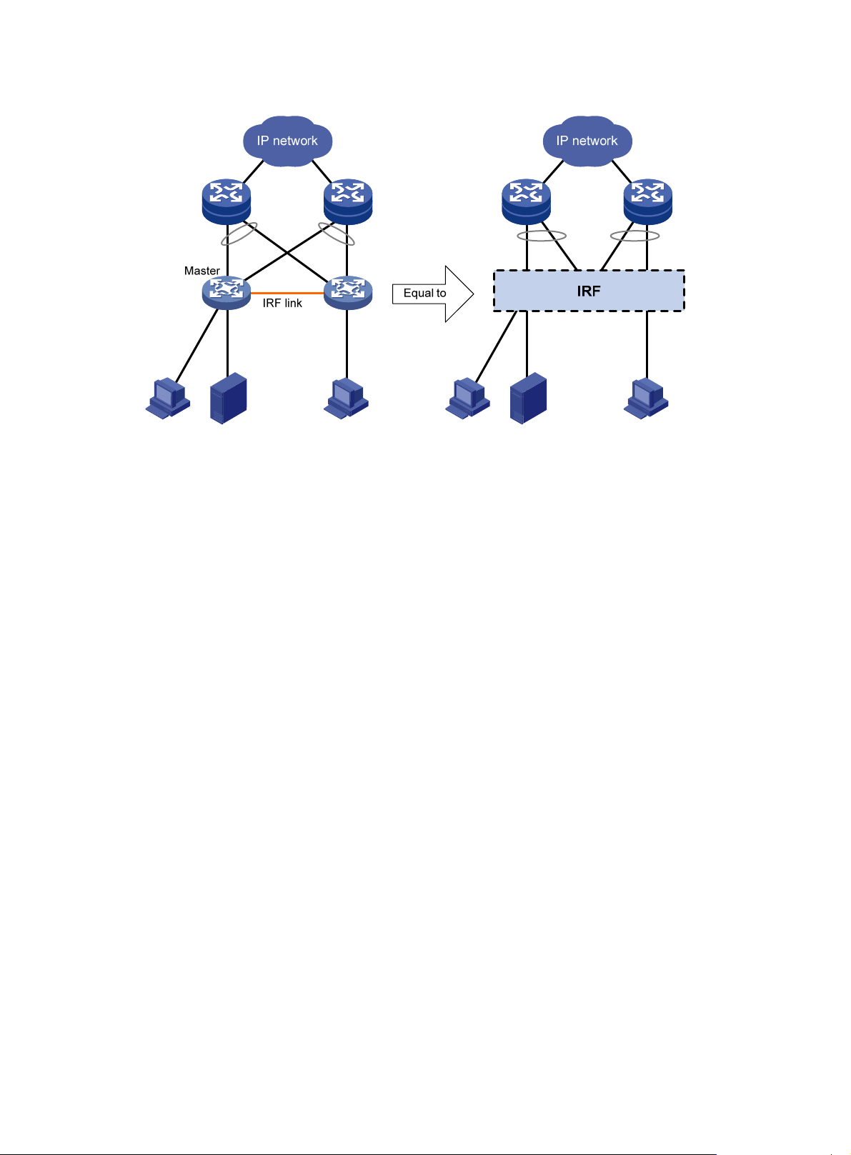
Figure 1 IRF application scenario
Basic concepts
This section describes the basic concepts that you might encounter when working with IRF.
IRF member roles
IRF uses two member roles: master and slave (called "subordinate" throughout the documentation).
When switches form an IRF fabric, they elect a master to manage the IRF fabric, and all other
switches back up the master. When the master switch fails, the other switches automatically elect a
new master from among them to take over . For more information about maste r election, see "Master
n."
electio
IRF member ID
An IRF fabric uses member IDs to uniquely identify and manage its members. This member ID
information is included as the first part of interface numbers and file paths to uniquely identify
interfaces and files in an IRF fabric. For more information about interface and file path naming, see
"Interface naming conventions" an
If two switches have the same IRF member ID, they cannot form an IRF fabric.
IRF port
An IRF port is a logical interface for the connection between IRF member devices. Every
IRF-capable device supports two IRF ports. The IRF ports are named IRF-port n/1 and IRF-port n/2,
where n is the member ID of the switch. The two IRF ports are referred to as "IRF-port 1" and
"IRF-port 2" in this book for simplicity.
d "File system naming conventions."
To use an IRF port, you must bind at least one physical port to it. The physical ports assigned to an
IRF port automatically form an aggregate IRF link. An IRF port goes down only if all its physical IRF
ports are down.
2
Page 7
For two neighboring devices, their IRF physical links must be bound to IRF-port 1 on one device and
to IRF-port 2 on the other.
Physical IRF port
Physical IRF ports connect IRF member devices and must be bound to an IRF port. They forward
IRF protocol packets between IRF member devices and data packets that must travel across IRF
member devices.
For more information about physical ports that can be used for IRF links, see "General restrictions
and configu
ration guidelines."
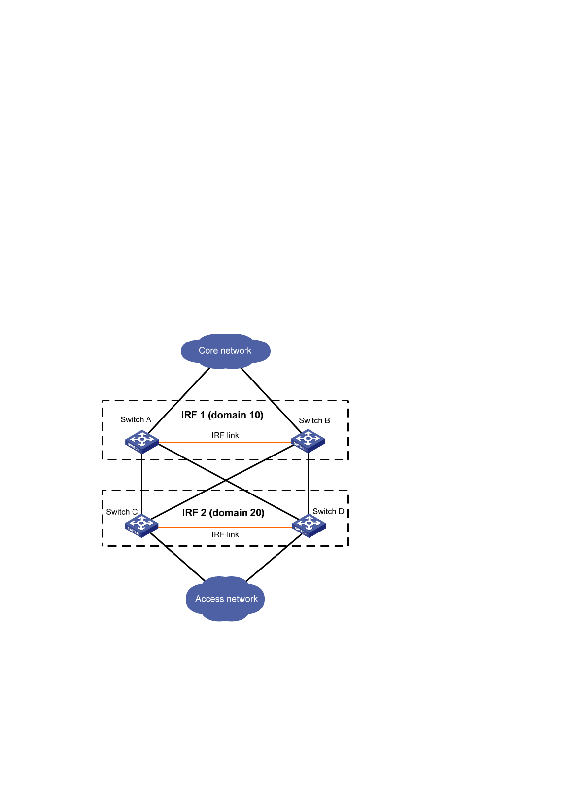
IRF domain ID
One IRF fabric forms one IRF domain. IRF uses IRF domain IDs to uniquely identify IRF fabrics and
prevent IRF fabrics from interfering with one another.
As shown in Figure 2, Swit
fabric 2. The fabrics have LACP MAD detection links between them. When a member switch
receives an extended LACPDU for MAD, it checks the domain ID to see whether the packet is from
the local IRF fabric. Then, the switch can handle the packet correctly.
Figure 2 A network that contains two IRF domains
ch A and Swit ch B form IRF fabric 1, and Switch C and Switch D form IRF
IRF split
IRF split occurs when an IRF fabric breaks up into two or more IRF fabrics because of IRF link
failures, as shown in Figure 3. Th
routing and forwarding problems on the network. To quickly detect a multi-active collision, configure
at least one MAD mechanisms (see "IRF multi-active detection")
e split IRF fabrics operate with the same IP address and cause
.
3
Page 8
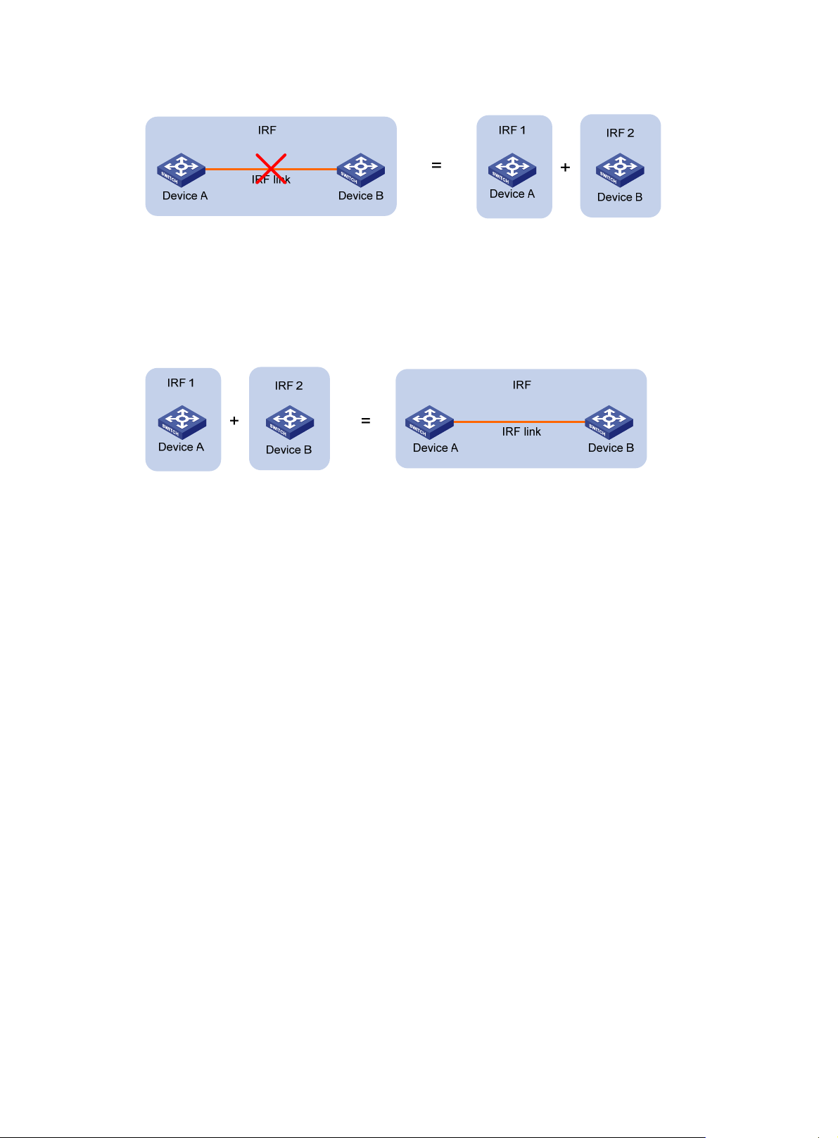
Figure 3 IRF split
IRF merge
IRF merge occurs when two split IRF fabrics reunite or when two independent IRF fabrics are united,
as shown in Figure 4.
Figure 4
IRF merge
Member priority
Member priority determines the possibility of a member device to be elected the master. A member
with higher priority is more likely to be elected the master.
The default member priority is 1. You can change the member priority of a member device to affect
the master election result.
Interface naming conventions
An interface is named in the format of chassis-id/slot-number/port-index, where:
• chassis-id—IRF member ID of the switch. This argument defaults to 1.
• slot-number—Represents the slot number of the interface card. This argument takes 0 for the
fixed ports on the front panel. If the switch has one expansion interface slot, this argument takes
1 for the slot. If the switch has two expansion interface slots, this argument takes 1 and 2 for the
slots from left to right.
• port-index—Port index depends on the number of ports available on the switch. To identify the
index of a port, look at its port index mark on the chassis.
For one example, on the standalone switch Sysname, GigabitEthernet 1/0/1 represents the first fixed
port on the front panel. Set its link type to trunk, as follows:
<Sysname> system-view
[Sysname] interface gigabitethernet 1/0/1
[Sysname-GigabitEthernet1/0/1] port link-type trunk
For another example, on the IRF fabric Master, GigabitEthernet 3/0/1 represents the first fixed port
on the front panel of member switch 3. Set its link type to trunk, as follows:
<Master> system-view
[Master] interface gigabitethernet 3/0/1
[Master-GigabitEthernet3/0/1] port link-type trunk
4
Page 9

File system naming conventions
On a standalone switch, you can use the name of storage device to access its file system. For more
information about storage device naming conventions, see Fundamentals Configuration Guid e.
On an IRF fabric, you can use the name of storage device to access the file system of the master. To
access the file system of any other member switch, use the name in the
slotmember-ID#storage-device-name format. For example:
To access the test folder under the root directory of the Flash on the master switch:
<Master> mkdir test
...
%Created dir flash:/test.
<Master> dir
Directory of flash:/
0 -rw- 10105088 Apr 26 2000 13:44:57 test.bin
1 -rw- 2445 Apr 26 2000 15:18:19 config.cfg
2 drw- - Jul 14 2008 15:20:35 test
515712 KB total (505812 KB free)
To create and access the test folder under the root directory of the Flash on member switch 3:
<Master> mkdir slot3#flash:/test
%Created dir slot3#flash:/test.
<Master> cd slot3#flash:/test
<Master> pwd
slot3#flash:/test
Or:
<Master> cd slot3#flash:/
<Master> mkdir test
%Created dir slot3#flash:/test.
To copy the file test.bin on the master to the root directory of the Flash on member switch 3:
# Display the current working path. In this example, the current working path is the root directory of
the Flash on member switch 3.
<Master> pwd
slot3#flash:
# Change the current working path to the root directory of the Flash on the master switch:
<Master> cd flash:/
<Master> pwd
flash:
# Copy the file to member switch 3.
<Master> copy test.bin slot3#flash:/
Copy flash:/test.bin to slot3#flash:/test.bin?[Y/N]:y
%Copy file flash:/test.bin to slot3#flash:/test.bin...Done.
Configuration synchronization mechanism
IRF uses a strict running-configuration synchronization mechanism so all chassis in an IRF fabric
can work as a single node, and after the master fails, other members can operate normally.
5
Page 10

In an IRF fabric, all chassis get and run the running configuration of the master. Any configuration
you have made is propagated to all members.
When you execute the save [ safely ] [ backup | main ] [ force ] command or the save file-url all
command, the system saves the running configuration, as follows:
• If the configuration auto-update function (the slave auto-update config command) is en abled,
saves the configuration as the startup configuration on all member switches for the next startup .
• If the configuration auto-update function is disabled, saves the configuration as the startup
configuration on the master for the next startup.
By default, configuration auto-update is enabled.
For more information about configuration management, see Fundamentals Configuration Guide.
Master election
Master election is held each time the IRF fabric topology changes, for example, when the IRF fabric
is established, a new member device is plugged in, the master device fails or is removed, the IRF
fabric splits, or IRF fabrics merge.
Master election uses the following rules in descending order:
1. Current master, even if a new member has higher priority.
When an IRF fabric is being formed, all member switches consider themselves as the master.
This rule is skipped.
2. Member with higher priority.
3. Member with the longest system uptime.
4. Member with the lowest bridge MAC address.
The IRF fabric is formed on election of the master.
During an IRF merge, the switches of the IRF fabric that fails the master election must reboot to
rejoin the IRF fabric that wins the election.
After a master election, all subordinate switches reboot with the configuration on the master. Their
original configuration, even if it has been saved, does not take effect.
IRF multi-active detection
An IRF link failure causes an IRF fabric to split in two IRF fabrics operating with the same Layer 3
configurations, including the same IP address. To avoid IP address collision and network problems,
IRF uses multi-active detection (MAD) mechanisms to detect the presence of multiple identical IRF
fabrics, handle collisions, and recover from faults.
Multi-active handling procedure
The multi-active handling procedure includes detection, collision handling, and failure recovery.
Detection
The MAD implementation of the switch detects active IRF fabrics with the same Layer 3 global
configuration by extending the LACP, BFD, or gratuitous ARP protocol.
These MAD mechanisms identify each IRF fabric with a domain ID and an active ID (the member ID
of the master). If multiple active IDs are detected in a domain, MAD determines that an IRF collision
or split has occurred.
Y ou can use at least one of these mechanisms in an IRF fabri c, depending on your network topology .
For a comparison of these MAD mechanisms, see "Configuring MAD."
6
Page 11

Collision handling
When multiple identical active IRF fabrics are detected, MAD compares the member IDs of their
masters. If the master in one IRF fabric has the lowest member ID among all the masters, the
members in the fabric continue to operate in Active state and forward traffic. MAD sets all the other
IRF fabrics in Recovery (disabled) state and shuts down all their physical ports but the console ports,
physical IRF ports, and any ports you have specified with the mad exclude interface command.
Failure recovery
To merge two split IRF fabrics, first repair the failed IRF link and remove the IRF link failure.
If the IRF fabric in Recovery state fails before the failure is recovered, repair the failed IRF fabric and
the failed IRF link.
If the IRF fabric in Active state fails before the failure is recovered, first enable the IRF fabric in
Recovery state to take over the active IRF fabric and protect the services from being affected. After
that, recover the MAD failure.
LACP MAD
LACP MAD requires that every IRF member have a link with an intermediate device, and all these
links form a dynamic link aggregation group, as shown in Figure 5. In
device must be an HPE device that supports extended LACP for MAD.
The IRF member switches send extended LACPDUs with TLVs that convey the domain ID and the
active ID of the IRF fabric. The intermediate device transparently forwards the extended LACPDUs
received from one member switch to all the other member switches:
• If the domain IDs and the active IDs in the extended LACPDUs sent by all the member devices
are the same, the IRF fabric is integrated.
• If the extended LACPDUs convey the same domain ID but different active IDs, a split has
occurred. To handle this situation, LACP MAD sets the IRF fabric with higher active ID in
Recovery state, and shuts down all its physical ports but the console port, IRF ports, and any
ports you have specified with the mad exclude interface command. The IRF fabric with lower
active ID is still in Active state and forwards traffic.
addition, the intermediate
7
Page 12
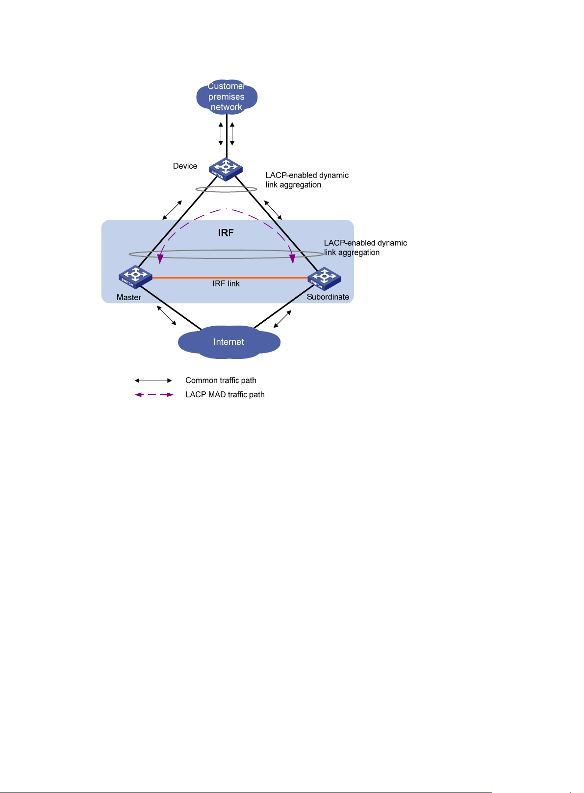
Figure 5 LACP MAD application scenario
BFD MAD
BFD MAD can work with or without intermediate devices. Figure 6 shows a typical BFD MAD
application scenario.
To use BFD MAD:
• Set up dedicated BFD MAD link between each pair of IRF members or between each IRF
member and the intermediate device. Do not use the BFD MAD links for any other purpose.
• Assign the ports connected by BFD MAD links to the same VLAN. Create a VLAN interface for
the VLAN, and assign a MAD IP address to each member on the VLAN interface.
The MAD addresses identify the member switches and must belong to the same subnet.
With BFD MAD, the master tries to establish BFD sessions with other member switches by using its
MAD IP address as the source IP address:
• If the IRF fabric is integrated, only the MAD IP address of the master is effective. The master
cannot establish a BFD session with any other member. If you execute the display bfd
session command, the state of the BFD sessions is Down.
• When the IRF fabric splits, the IP addresses of the masters in the split IRF fabrics take effect.
The masters can establish a BFD session. If you execute the display bfd session command,
the state of the BFD session between the two devices is Up.
8
Page 13
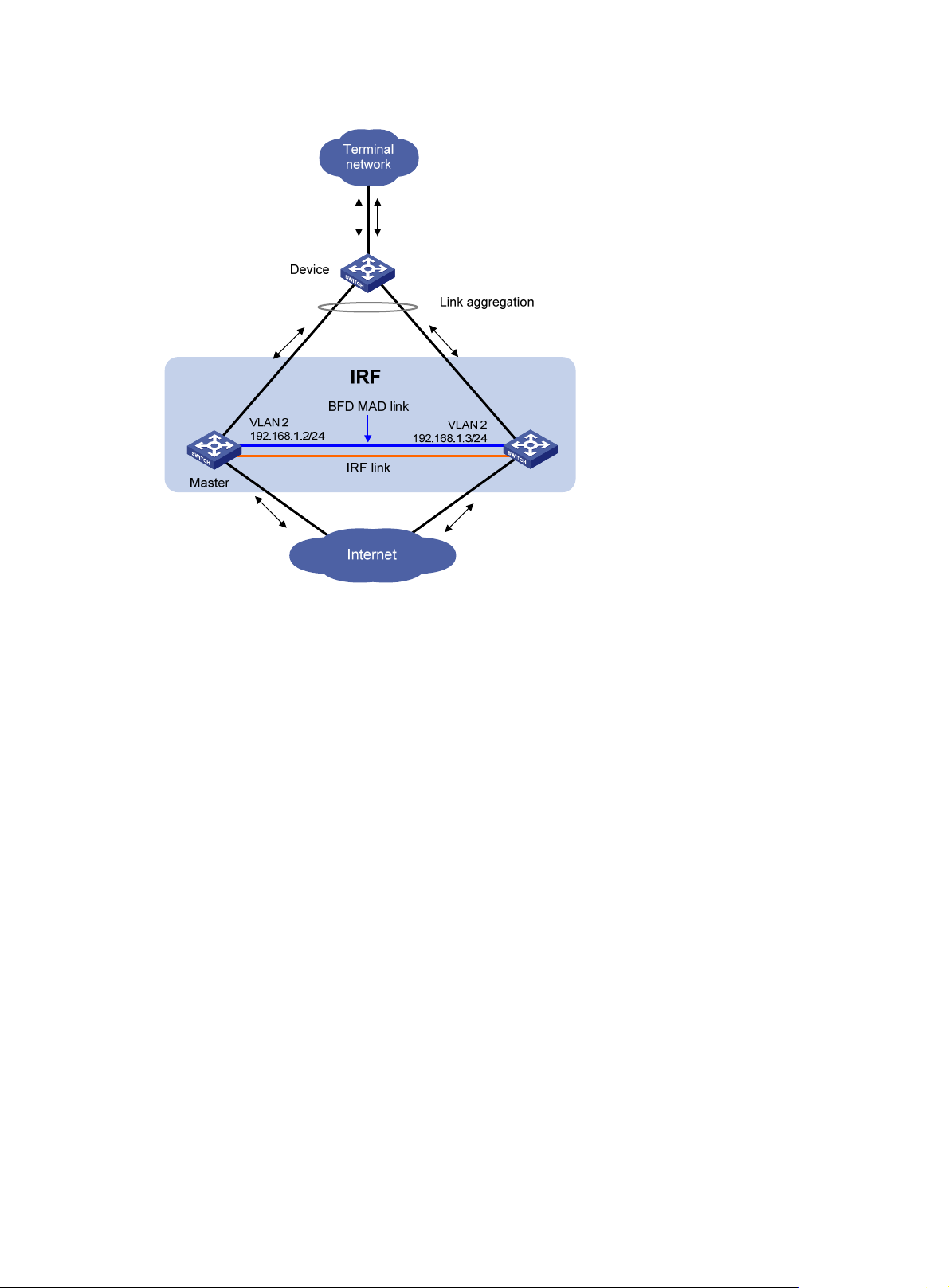
Figure 6 BFD MAD application scenario
ARP MAD
ARP MAD detects multi-active collisions by using extended gratuitous ARP packets that convey the
IRF domain ID and the active ID.
You can set up ARP MAD links between neighbor IRF member devices, or between each IRF
member device and an intermediate device (see Figure 7). If an i
must also run the spanning tree feature between the IRF fabric and the intermediate device.
ntermediate device is used, you
9
Page 14

Figure 7 ARP MAD application scenario
Each IRF member compares the domain ID and the active ID in incoming extended gratuitous ARP
packets with its domain ID and active ID:
• If the domain IDs are different, the extended gratuitous ARP packet is from a dif ferent IRF fabric.
The device does not continue to process the packet with the MAD mechanism.
• If the domain IDs are the same, the device compares the active IDs:
{ If the active IDs are different, the IRF fabric has split.
{ If the active IDs are the same, the IRF fabric is integrated.
10
Page 15
Configuring IRF
To ensure a successful IRF setup, read t he config uration re striction s and guidelines carefully before
you connect and set up an IRF fabric.
General restrictions and configuration guidelines
This section describes the restrictions and configuration guidelines you must follow.
Software requirements
All IRF member switches must run the same system software image version.
IRF link redundancy
The HPE 5800 and 5820X switches support up to four physical ports for an IRF port.
IRF physical port restrictions and cabling requirements
Candidate IRF physical ports include the SFP+ ports on the front panel and the SFP+ ports on
expansion interface cards. Expansion interface cards must be purchased separately.
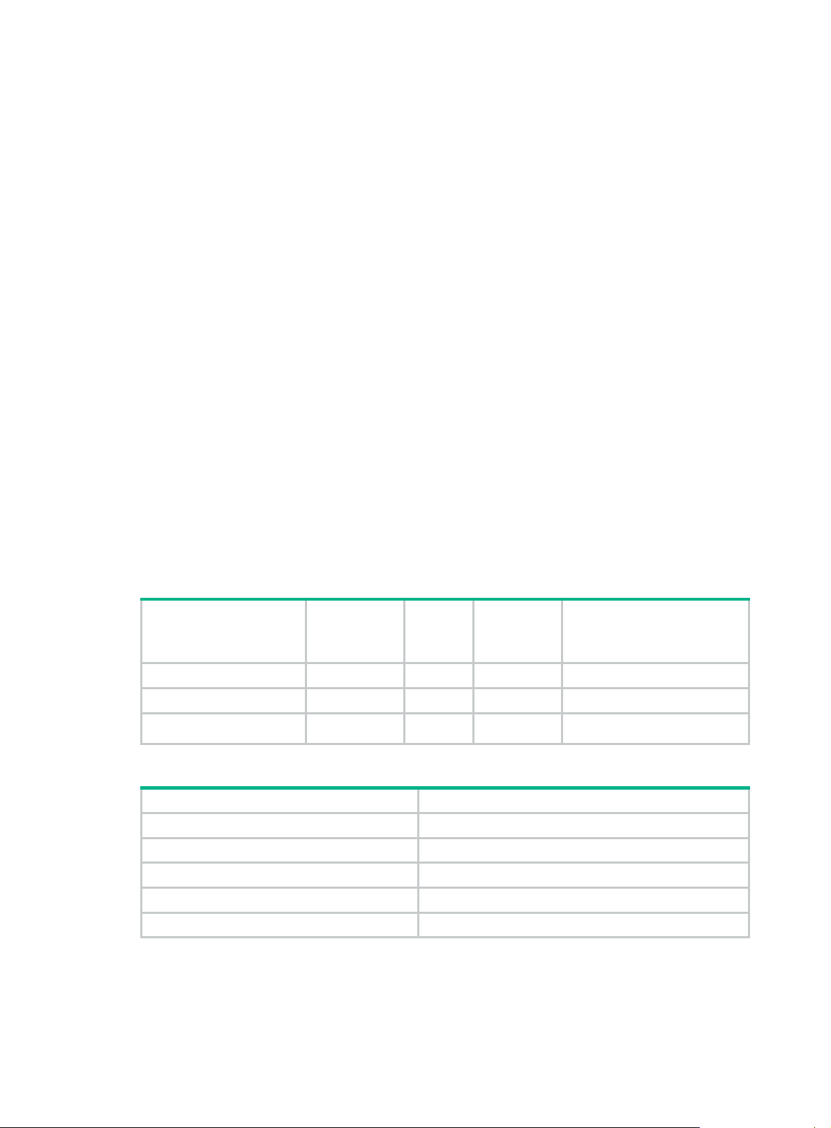
For long-distance IRF connections, use the SFP+ transceiver modules in Table 1. For
IRF connections, use the SFP+ cables in Table 2.
Table 1
Table 2 SFP+ cables available for the SFP+ ports
For more information about transceiver modules, see HPE Comware-Based Devices Transceiver
Modules User Guide.
10 Gbps SFP+ transceiver modules available for the SFP+ ports
Central
Module
SFP-XG-SX-MM850-A 850 LC 50/125 300 m (984.25 ft)
SFP-XG-LX220-MM1310 1310 LC 62.5/125 220 m (721.78 ft)
SFP-XG-LX-SM1310 1310 LC 9/125 10 km (6.21 miles)
Cable description Cable length
LSWM1STK 0.65 m (2.13 ft)
LSWM2STK 1.2 m (3.94 ft)
LSWM3STK 3 m (9.84 ft)
LSTM1STK 5 m (16.40 ft)
LSWM4STK 10 m (32.81 ft)
wavelength
(nm)
Connec
tor
Fiber
diameter
(µm)
Maximum transmission
distance
short-distance
11
Page 16

The SFP+ modules and SFP+ cables available for the switch are subject to change over time. For
the most up-to-date list of SFP+ modules and cables, contact Hewlett Packard Enterprise technical
support or marketing staff.
IRF port binding restrictions
Chassis
• 5800-48G-PoE+ Switch
with 2 Interface Slots
(JC101A/JC101B)
• 5800-48G-PoE+ TAA
Switch with 2 Interface
Slots
(JG242A/JG242B)
5800AF-48G Switch
(JG225A/JG225B)
• 5800-48G Switch with 1
Interface Slot
(JC105A/JC105B)
• 5800-48G TAA Switch
with 1 Interface Slot
(JG258A/JG258B)
• 5800-48G-PoE+ Switch
with 1 Interface Slot
(JC104A/JC104B)
• 5800-48G-PoE+ TAA
Switch with 1 Interface
Slot (JG257A/JC257B)
• 5800-24G Switch
(JC100A/JC100B)
• 5800-24G TAA Switch
(JG255A/JG255B)
• 5800-24G-PoE+ Switch
(JC099A/JC099B)
• 5800-24G-PoE+TAA
Switch
(JG254A/JG254B)
• 5800-24G-SFP Switch
with 1 Interface Slot
(JC103A/JC103B)
• 5800-24G-SFP TAA
Switch with 1 Interface
Slot (JG256A/JG256B)
• 5820X-14XG-SFP+
Switch with 2 Interface
Slots (JC106A/JC106B)
• 5820X-14XG-SFP+
TAA Switch with 2
Interface Slots
(JG259A/JG259B)
Candidate physical IRF
ports
Ports on the expansion interface
cards on the front panel
The six fixed SFP+ ports (in two
groups) on the front panel:
• SFP+ ports 49, 50, and 52 in
one group
• SFP+ ports 51, 53, and 54 in
the other group
• The four fixed SFP+ ports on
the front panel
• Ports on the expansion
interface card on the rear
panel
• The four fixed SFP+ ports on
the front panel
• Ports on the expansion
interface card on the rear
panel
• The four fixed SFP+ ports on
the front panel
• Ports on the expansion
interface card on the front
panel
• The 14 fixed SFP+ ports on
the front panel
• Ports on the expansion
interface card on the front
panel
Requirements
All physical ports of an IRF port must
be located on the same interface card.
All physical ports of an IRF port must
be in the same group.
All physical ports of an IRF port must
be located on the front panel or the
interface card on the rear panel.
No location restriction for the physical
ports of an IRF port.
No location restriction for the physical
ports of an IRF port.
No location restriction for the physical
ports of an IRF port.
12
Page 17

Chassis
• 5820X-24XG-SFP+
Switch
(JC102A/JC102B)
• 5820X-24XG-SFP+
TAA-compliant Switch
(JG243A/JG243B)
• 5820AF-24XG Switch
(JG219A/JG219B)
Candidate physical IRF
ports
The 24 fixed SFP+ ports on the
front panel
MAD
• Configure at least one MAD mechanism for prompt IRF split detection and I RF fabric re covery.
• If LACP MAD or ARP MAD runs between two IRF fabrics, assign each fabric a unique IRF
domain ID. (For BFD MAD, this task is optional.)
• To exclude a port from the shutdown action that is executed when a n IRF fabric transits to the
Recovery state, use the mad exclude interface command. To bring up a port after the IRF
fabric transits to the Recovery state, you must use the mad restore command instead of the
undo shutdown command.
FIPS mode requirement
Requirements
No location restriction for the physical
ports of an IRF port.
To form an IRF fabric, all member devices must use the same FIPS mode setting (configurable with
the fips mode enable command). For more information about FIPS mode, see Security
Configuration Guide.
Other configuration guidelines
• Strictly follow the IRF fabric setup procedure described in "Setup and configuration task list" to
plan the IRF fabric, identify IRF physical ports, connect IRF member switches, and configure
basic settings.
• Assign each member a unique IRF member ID to make sure they can merge. You must reboot
the members to validate the IRF member ID settings.
• Assign the highest member priority to the device you want to use as the master.
• Before removing an interface card that has physical IRF ports in an IRF fabric, remove the IRF
connection cables, or use the shutdown command to shut down the IRF physical ports.
• If a subordinate switch uses the same next-startup configuration file name as the master switch,
the file might be overwritten depending on your configuration file management settings. To
continue to use the configuration file after removing the switch from the IRF fabric, back up the
file before setting up the IRF fabric.
• Save any configuration you have made to the startup configuration file before rebooting the IRF
member devices.
• The Layer 3 Ethernet port in this book refers to an Ethernet port that can perform IP routing and
inter-VLAN routing. You can set an Ethernet port as a Layer 3 Ethernet interface by using the
port link-mode route command (see Layer 2—LAN Switching Configuration Guide).
13
Page 18

Setup and configuration task list
Hewlett Packard Enterprise recommends the basic IRF setup procedure in Figure 8. Perform the
tasks in this figure on each member switch. After the IRF fabric is set up, you can access the IRF
fabric to manage its member switches as if they were one switch.
Figure 8 Basic IRF setup flow chart
Hewlett Packard Enterprise recommends the following IRF fabric setup and configuratio n procedure:
Task Remarks
1. Planning the IRF fabric setup
2. Assigning a member ID to each IRF member switch
Required.
Required.
Perform this task on each
member switch.
3. Specifying a priority for each member switch
4. Connecting physical IRF ports
5. Binding physical ports to IRF ports
6. Accessing the IRF fabric:
{ Accessing the CLI of the master switch
{ Accessing the CLI of a subordin ate switch
7. Assigning an IRF domain ID to the IRF fabric
8. Configuring a member switch description
9. Configuring IRF link load sharing mode:
{ Configuring the global load sharing mode
{ Configuring a port-specific load sharing mode
10. Configuring IRF bridge MAC persistence
Required.
Perform this task on each
member switch.
Required.
Required.
Perform this task on each
member switch.
Login to the master's CLI is
required. You configure all
member switches at the master's
CLI.
From the master's CLI, you can
log in to any other member
switch's CLI to execute a limited
set of maintenance commands.
This task is required for ARP
MAD and LACP MAD.
Optional.
Optional.
Optional.
14
Page 19

Task Remarks
Optional.
11. Enabling software auto-update for system software image
synchronization
Hewlett Packard Enterprise
recommends enabling software
auto-update to make sure system
software image synchronization
12. Setting the IRF link down report delay
13. Configuring MAD:
{ Configuring LACP MAD
{ Configuring BF D MAD
{ Configuring ARP MAD
{ Excluding a port from the shutdown action upon detection of
multi-active collision
{ Recovering an IRF fabric
Planning the IRF fabric setup
Consider the following items when you plan an IRF fabric:
• Hardware compatibility and restrictions
• IRF fabric size
• Master switch
• IRF physical ports
• Member ID and priority assignment scheme
• Fabric topology and cabling scheme
For more information about hardware and cabling, see the switch installation guide.
Optional.
Required.
MAD mechanisms are
independent of one another. You
can configure at least one MAD
mechanism for an IRF fabric.
Assigning a member ID to each IRF member switch
CAUTION:
In an IRF fabric, changing IRF member IDs might cause undesirable configuration changes and
even data loss. Before you do that, back up the configuration and make sure you fully understand
the impact on your network. For example, all member switches in an IRF fabric are the same model.
If you swapped the IDs of any two members, their interface settings would also be swapped.
By default, the member IDs of all switches are 1. To create an IRF fabric, you must assign a unique
IRF member ID to each switch.
Perform this task before the IRF fabric is formed. T o prevent any undesirabl e configuration change or
data loss, avoid changing member IDs after the IRF fabric is formed.
The new member ID takes effect at a reboot. After the switch reboots, the settings on all member-ID
related physical resources (including common physical network ports) are removed, regardless of
whether you have saved the configuration.
To set a member ID for a switch:
15
Page 20

Step Command Remarks
1. Enter system view.
2. Assign an IRF member ID
to the switch.
3. Save the configuration.
4. Reboot the switch.
system-view
irf member
new-member-id
save
force
[
reboot
safely
[
]
[
member-id
] [
slot
slot-number ] N/A
backup
renumber
main
|
]
N/A
The default IRF member ID is 1.
Optional.
If you have bound physical
ports to IRF ports or assigned
member priority, save the
configuration before rebooting
the switch so these settings can
continue to take effect after the
reboot.
Specifying a priority for each member switch
IRF member priority represents the possibility for a device to be elected the master in an IRF fabric.
The higher the priority, the higher the possibility.
A member priority change affects the election result at the next master election, but does not cause
immediate master re-election.
To specify a priority for the switch:
Step Command Remarks
1. Enter system view.
2. Specify a priority for the
switch.
system-view
irf member
priority
member-id
priority
Connecting physical IRF ports
When you connect two neighboring IRF members, connect the physical ports of IRF-port 1 on one
member to the physical ports of IRF-port 2 on the other, as shown in Figure 9.
IMPORTANT:
No intermediate devices are allowed between neighboring members.
Figure 9 Connecting IRF physical ports
Connect the switches into a daisy chain topology or a ring topology. A ring topology is more reliable
(see Figure 1 0). In ring top
daisy chain topology. Rather, the IRF fabric changes to a daisy chain topology without interrupting
network services.
ology , the failure of one IRF link does not cause the IRF fabric to split as in
N/A
The default IRF member priority
is 1.
16
Page 21

Figure 10 Daisy chain topology versus ring topology
IRF
Master
IRF-Port2
Master
IRF-Port1
Subordinate
IRF-Port1
Subordinate
IRF-Port2
Subordinate Subordinate
IRF-Port1 IRF-Port2
IRF
IRF-Port2
IRF-Port1
Ring topology
Daisy chain
topology
Binding physical ports to IRF ports
To establish an IRF connection between two devices, you must bind at least one physical port to
IRF-port 1 on one device and to IRF-port 2 on the other. For link redundan cy and load sharin g, bind
multiple physical ports to one IRF port.
When you bind physical ports to IRF ports, follow the restrictions in "IRF port binding restrictions."
hysical port that has been bound to an IRF port, you can only use th e cfd, default, shutdown,
On a p
description, and flow-interval commands. For more information about these commands, see Layer
2—LAN Switching Command Reference.
IRF-Port2IRF-Port1
To bind physical ports to IRF ports:
Step Command Remarks
1. Enter system view.
2. Enter Ethernet interface
view or interface range
view.
system-view
• Enter interface range view:
{ Approach 1:
interface range
{ interface-type
interface-number [ to
interface-type
interface-number ] }
&<1-5>
{ Approach 2:
interface range name
name [ interface
{ interface-type
interface-number [ to
interface-type
interface-number ] }
&<1-5> ]
• Enter interface view:
interface interface-type
interface-number
N/A
To shut down a range of physical
IRF ports, enter interface range
view.
To shut down one physical IRF port,
enter its interface view.
17
Page 22

Step Command Remarks
Always shut down a physical port
before binding it to an IRF port or
removing the binding.
3. Shut down the port or ports.
4. Return to system view.
5. Enter IRF port view.
shutdown
quit
irf-port
member-id/port-number N/A
Start the shutdown operation on the
master and then the switch that has
the fewest number of hops from the
master.
N/A
6. Bind each physical port to
the IRF port.
7. Return to system view.
8. Enter Ethernet interface
view or interface range
view.
9. Bring up the port or ports.
10. Return to system view.
11. Save the running
configuration.
port group interface
interface-type interface-number
mode
[
quit
• Enter interface range view:
• Enter interface view:
undo shutdown
quit
save
enhanced
{
{ Approach 1:
interface range
{ interface-type
interface-number [ to
interface-type
interface-number ] }
&<1-5>
{ Approach 2:
interface range name
name [ interface
{ interface-type
interface-number [ to
interface-type
interface-number ] }
&<1-5> ]
interface interface-type
interface-number
normal
|
} ]
By default, no physical port is bound
to any IRF port.
Make sure the two ends of an IRF
link use the same binding mode.
N/A
N/A
N/A
N/A
N/A
After this step is performed, the
state of the IRF port changes to UP,
the member switches automatically
12. Activate the IRF port
configuration.
irf-port-configuration active
elect a master, and the subordinate
switch automatically reboots.
After the IRF fabric is formed, you
can add more physical ports to an
IRF port (in UP state) without
performing this step.
Accessing the IRF fabric
The IRF fabric appears as one device after it is formed. You configure and manage all IRF members
at the CLI of the master. All settings you have made are automatically propagated to the IRF
members.
18
Page 23

When you log in to an IRF fabric, you are placed at the CLI of the master, regardless of at which
member switch you are logged in. After that, you can access the CLI of a subordinate switch to
execute a limited set of maintenance commands.
The IRF fabric supports up to 16 concurrent VTY users. The maximum number of concurrent
console users equals the total number of member switches in the IRF fabric.
Accessing the CLI of the master switch
Access an IRF fabric in one of the following ways:
• Local login—Log in through the console port of any member switch.
• Remote login—Remotely log in at a Layer 3 Ethernet interface on any member switch by using
a methods including Telnet, Web, and SNMP.
For more information, see the chapter on login in Fundamentals Configuration Guide.
Accessing the CLI of a subordinate switch
You can log in to the CLI of a subordinate switch for maintenance or debugging. At the CLI of a
subordinate switch, you are placed in user view, and the command prompt changes to
<Sysname-Slave#member-ID/slot-number>, for example, <Sysname-Slave#2>. You can use the
following commands at a subordinate switch's CLI:
• display
• quit
• return
• system-view
• debugging
• terminal debugging
• terminal logging
• terminal monitor
• terminal trapping
Perform the following task in user view:
Task Command Remarks
Log in to a subordinate switch.
irf switch-to
member-id
By default, you are placed at the
master's CLI.
To return to the master's CLI, use the quit command.
Assigning an IRF domain ID to the IRF fabric
This task is required for running LACP MAD or ARP MAD between two IRF fabrics. For BFD MAD,
this task is optional.
To assign a domain ID to an IRF fabric:
Step Command Remarks
1. Enter system view.
2. Assign a domain ID to the
IRF fabric.
system-view
irf domain
domain-id
19
N/A
By default, the domain ID of an IRF fabric is
0.
Page 24

Configuring a member switch description
You can configure a description to describe the location or purpose of a member switch.
To configure a description for a member switch:
Step Command Remarks
1. Enter system view.
2. Configure the description of
a member.
system-view
irf member
text
member-id
description
N/A
By default, no member switch
description is configured.
Configuring IRF link load sharing mode
On an IRF port, traffic is balanced across its physical links.
Y ou can co nfigure the IRF port to distribute traf fic based on any combination of the following criteria:
• Source IP address
• Destination IP address
• Source MAC address
• Destination MAC address
If a criteria combination is not supported, the system displays an error message.
Configure the IRF link load sharing mode for IRF links in system view or IRF port view.
• In system view, the configuration is global and takes effect on all IRF ports.
• In IRF port view, the configu ration is port specific and takes effect onl y on the specified IRF port.
An IRF port preferentially uses the port-specific load sharing mode. If no port-specific load sharing
mode is available, an IRF port uses the global load sharing mode.
Configuring the global load sharing mode
Step Command Remarks
1. Enter system view.
2. Configure the global
IRF link load sharing
mode.
system-view
irf-port load-sharing mode
destination-ip
{
source-ip
|
destination-mac
|
source-mac
} *
N/A
|
By default, the switch
automatically distributes traffic
based on their packet type.
Configuring a port-specific load sharing mode
Before you configure a port-specific load sharing mode, make sure you have bound at least two
physical ports to the IRF port.
To configure a port-specific load sharing mode for an IRF port:
Step Command Remarks
1. Enter system view.
system-view
N/A
20
Page 25

Step Command Remarks
2. Enter IRF port view.
3. Configure the
port-specific load
sharing mode.
irf-port
member-id/port-number N/A
irf-port load-sharing mode
destination-ip
{
source-ip
|
destination-mac
|
source-mac
|
} *
By default, the switch
automatically distributes traffic
based on their packet type.
Configuring IRF bridge MAC persistence
By default, an IRF fabric uses the bridge MAC address of the master switch as its bridge MAC
address. Layer 2 protocols, such as LACP, use this bridge MAC address to identify the IRF fabric. On
a switched LAN, the bridge MAC address must be unique.
To avoid duplicate bridge MAC addresses, an IRF fabric can change its bridge MAC address
automatically after its master leaves. However, the change can cause transient traffic interruption.
Depending on the network condition, enable the IRF fabric to preserve or change its bridge MAC
address after the master leaves. Available options include:
• irf mac-address persistent timer—Bridge MAC address of the IRF fabric is retained for 6
minutes after the master leaves. If the master does not return before the timer expires, the IRF
fabric uses the bridge MAC address of the new master as its bridge MAC address. This option
avoids unnecessary bridge MAC address change caused by devi ce reboot, transient link failure,
or purposeful link disconnection.
• irf mac-address persistent always—Bridge MAC address of the IRF fabric does not chan ge
after the master leaves.
• undo irf mac-address persistent—Bridge MAC address of the new master replaces the
original one as soon as the old master leaves.
IMPORTANT:
If ARP MAD is used, configure the undo irf mac-address persistent command to enable
immediate bridge MAC address change after a master re-election.
If two IRF fabrics have the same bridge MAC address, they cannot merge.
To configure the IRF bridge MAC persistence setting:
Step Command Remarks
1. Enter system view.
2. Configure IRF bridge MAC
persistence.
system-view
• Retain the bridge MAC address
even if the master has changed:
irf mac-address persistent
always
• Preserve the bridge MAC
address for 6 minutes after the
master leaves:
irf mac-address persistent
timer
• Change the bridge MAC
address as soon as the master
leaves:
undo irf mac-address
persistent
N/A
By default, the IRF fabric's
bridge MAC address persists
permanently even after the
master leaves.
21
Page 26
Enabling software auto-update for system software image synchronization
To join an IRF fabric, a switch must use the same syst em software image as the master in the fabric.
The software auto-update function automatically propagates the system software image of the
master to all members in the IRF fabric. If software auto-update is disabled, you must manually
update the switch with the system software image of the master.
When you add a switch to the IRF fabric, the software auto-update function compares the system
software versions of the switch and the IRF master . If the version s are dif ferent, the switch perform s
the following tasks automatically:
1. Downloads the system software image from the master.
2. Sets the downloaded image as the system software for the next startup.
3. Reboots with the new system software image to rejoin the IRF fabric.
Before you use the software auto-update function, make sure the following requirements are met:
• The switch you are adding to the IRF fabric is compatible with the software version running on
the master. If the software versio ns are incom patible, the software auto-update function cannot
correctly work.
• The switch you are adding to the IRF fabric has sufficient space for the new system software
image.
T o enable the IRF fabric to automatically synchronize the system software of the master to the switch
you are adding to the IRF fabric:
Step Command Remarks
1. Enter system view.
2. Enable the software
auto-update function.
In an IRF fabric enabled with software auto-update, if a software upgrade requires upgrading the
Boot ROM image, use the following upgrading procedure:
1. Download the new system software image to the master device.
2. Use the bootrom update command to upgrade the Boot ROM image on the master.
This step guarantees that the master can complete startup prior to other member switches.
3. Use the boot-loader file file-url slot slot-number main command to specify the system
software image as the startup image for the master.
4. Reboot the entire IRF fabric to complete upgrading software.
For the system software image and Boot ROM compatibility, see the release notes for the new
software release.
system-view
irf auto-update enable
N/A
By default, this function is
disabled.
Setting the IRF link down report delay
To prevent frequent IRF splits and merges at times of link flapping, configure the IRF ports to delay
reporting link down events. An IRF port works as follows:
• When the IRF link changes from up to down, the port does not immediately report the change to
the IRF fabric. If the IRF link state is still down when the delay time is reached, the port reports
the change to the IRF fabric.
• When the IRF link changes from down to up, the link layer immediately reports th e event to the
IRF fabric.
22
Page 27

To set the IRF link down report delay:
Step Command Remarks
1. Enter system view.
2. Set the IRF link down
report delay.
Configuring MAD
The following MAD mechanisms are available for detecting multi-active collisions in diff erent network
scenarios:
• LACP MAD
• BFD MAD
• ARP MAD
system-view
irf link-delay
interval
N/A
The default IRF link down report delay is 4
seconds.
Hewlett Packard Enterprise recommends
setting the delay to 0 seconds in the
following situations:
• The IRF fabric requires a fast
master/subordinate or IRF link
switchover.
• The BFD or GR feature is used.
These MAD detection mechanisms operate independently. You can configure all of them for an IRF
fabric.
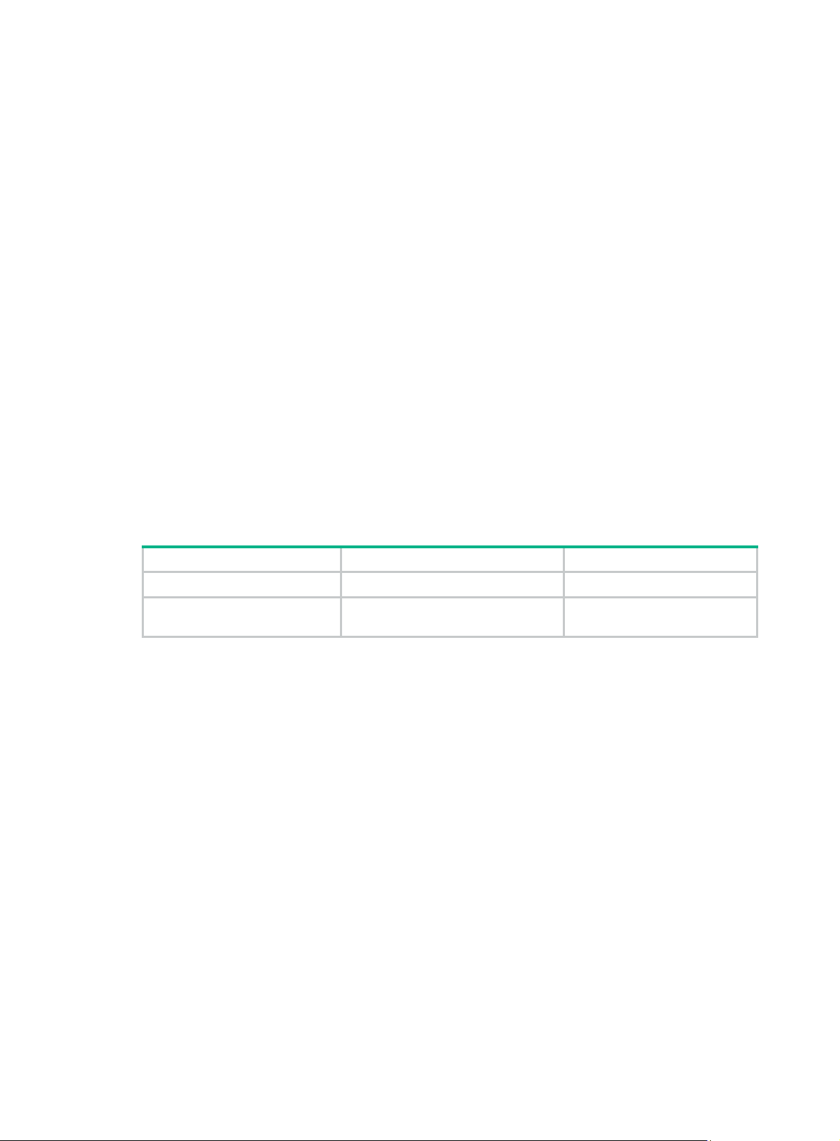
Table 3 provi
des a reference for you to make a MAD mechanism selection decision.
Table 3 A comparison of the MAD mechanisms
MAD
mechanism
LACP MAD
BFD MAD
Advantages Disadvantages Application scenario
Link aggregation is used
between the IRF fabric
• Detection speed is fast.
• Requires no
MAD-dedicated physical
ports or interfaces.
• Detection speed is fast.
• No intermediate device is
required.
• Intermediate device, if
used, can come from any
vendor.
Requires an intermediate
HPE device that supports
LACP MAD packets.
• Requires MAD
dedicated physical
ports and Layer 3
interfaces, which
cannot be used for
transmitting user
traffic.
• If no intermediate
device is used, the IRF
members must be fully
meshed.
• If an intermediate
device is used, every
IRF member must
connect to the
intermediate device.
and its upstream or
downstream device.
For information about
LACP, see Layer
2—LAN Switching
Configuration Guide.
• No special
requirements for
network scenarios.
• If no intermediate
device is used, this
mechanism is only
suitable for IRF
fabrics that have a
small number of
members that are
geographically
close to one
another.
For information about
BFD, see High
Availability Configuration
Guide.
23
Page 28

MAD
mechanism
ARP MAD
Advantages Disadvantages Application scenario
• No intermediate device is
required.
• Intermediate device, if
used, can come from any
vendor.
• Requires no MAD
dedicated ports.
Configuring LACP MAD
When you use LACP MAD, follow these guidelines:
• The intermediate device must be an HPE device that support extended LACP for MAD.
• If the intermediate device is also an IRF fabric, assign the two IRF fabrics different domain IDs
for correct split detection.
• Use dynamic link aggregation mode. MAD is LACP dependent. Even though LACP MAD can
be configured on both static and dynamic aggregate interfaces, it takes effect only on dynamic
aggregate interfaces.
• Configure link aggregation settings also on the intermediate device.
To configure LACP MAD:
• Detection speed is
slower than BFD MAD
and LACP MAD.
• The spanning tree
feature must be
enabled.
Spanning tree-enabled
non-link aggregation
IPv4 network scenario.
For information about
ARP, see Layer 3—IP
Services Configuration
Guide.
Step Command Remarks
1. Enter system view.
2. Assign a domain ID to the
IRF fabric.
3. Create an aggregate
interface and enter
aggregate interface view.
4. Configure the aggregation
group to operate in dynamic
aggregation mode.
5. Enable LACP MAD.
6. Return to system view.
7. Enter Ethernet interface
view.
8. Assign the Ethernet
interface to the specified
aggregation group.
system-view
irf domain
• Enter Layer 2 aggregate
• Enter Layer 3 aggregate
link-aggregation mode dynamic
mad enable
quit
interface
interface-number
port link-aggregation group
number
domain-id The default IRF domain ID is 0.
interface view:
interface bridge-aggregation
interface-number
interface view:
interface route-aggregation
interface-number
interface-type
N/A
Use either command.
Perform this step on the
intermediate device as well.
By default, an aggregation
group operates in static
aggregation mode.
Perform this step on the
intermediate device as well.
By default, LACP MAD is
disabled.
N/A
N/A
Perform this step on the
intermediate device as well.
24
Page 29

Configuring BFD MAD
When you use BFD MAD, follow these guidelines:
Category Restrictions and guidelines
• Do not enable BFD MAD on VLAN-interface 1.
BFD MAD VLAN
BFD MAD VLAN and
feature compatibility
MAD IP address
To configure BFD MAD:
• If you are using an intermediate device, assign the ports of BFD MAD
• The IRF fabrics in a network must use different BFD MAD VLANs.
• Do not use the BFD MAD VLAN for any other purpose. No Layer 2 or
• Disable the spanning tree feature on any Layer 2 Ethernet ports in the
• Do not bind a BFD MAD-enabled VLAN interface to any VPN instance.
• To avoid problems, only use the mad ip address command to configure
• All MAD IP addresses on the BFD MAD-enabled VLAN interface must be
links to the BFD MAD VLAN on the device.
Layer 3 features, including ARP and LACP, can work on the BFD
MAD-enabled VLAN interface or any port in the VLAN. If you configure
any other feature on the VLAN, neither the configured feature nor the
BFD MAD function can work correctly.
BFD MAD VLAN. The MAD function is mutually exclusive with the
spanning tree feature.
The MAD function is mutually exclusive with VPN.
IP addresses on the BFD MAD-enabled VLAN interface. Do not
configure an IP address with the ip address command or configure a
VRRP virtual address on the BFD MAD-enabled VLAN interface.
on the same subnet.
Step Command Remarks
1. Enter system view.
2. Create a VLAN dedicated to
BFD MAD.
3. Return to system view.
4. Enter Ethernet interface
view or interface range
view.
system-view
vlan-id
vlan
quit
• Enter interface range view:
{ Approach 1:
interface range
{ interface-type
interface-number [ to
interface-type
interface-number ] } &<1-5>
{ Approach 2:
interface range name
name [ interface
{ interface-type
interface-number [ to
interface-type
interface-number ] }
&<1-5> ]
• Enter Ethernet interface view:
interface interface-type
interface-number
N/A
The default VLAN on the switch
is VLAN 1.
N/A
To assign a range of ports to
the BFD MAD VLAN, enter
interface range view.
To assign one port to the BFD
MAD VLAN, enter Ethernet
interface view.
25
Page 30

Step Command Remarks
• Assign the port to the VLAN as
an access port:
port access vlan vlan-id
5. Assign the port or the range
of ports to the BFD MAD
VLAN.
6. Return to system view.
• Assign the port to the VLAN as a
trunk port:
port trunk permit vlan vlan-id
• Assign the port to the VLAN as a
hybrid port:
port hybrid vlan vlan-id
{ tagged | untagged }
quit
The link type of BFD MAD ports
can be access, trunk, or hybrid.
The default link type of a port is
access.
N/A
7. Enter VLAN interface view.
8. Enable BFD MAD.
9. Configure a MAD IP
address for a member
device on the VLAN
interface.
NOTE:
After a BFD MAD-enabled IRF fabric splits, route conflict messages (for example, %May 5
16:15:47:733 2010 HPE ARP/3/ROUTECONFLICT: Slot=5;Route conflict found,
IP:192.168.2.1, VrfIndex:0) might appear on the fabric part that does not have the original
master, because this fabric part still keeps the forwarding entries with the original master as the
destination. This message does not affect forwarding. The system stops generating it after the
forwarding entries are aged out.
Configuring ARP MAD
interface vlan-interface
interface-number
mad bfd enable
mad ip address
mask-length }
ip-address { mask |
member
member-id
N/A
By default, BFD MAD is
disabled.
By default, no MAD IP address
is configured on any VLAN
interface.
The MAD IP address must not
be on the same subnet as any
IP address configured on any
member device.
When you configure ARP MAD, follow these guidelines:
• If an intermediate device is used, you can use common data links as ARP MAD links. If no
intermediate device is used, set up dedicated ARP MAD links between IRF member devices.
• Do not use the VLAN configured for ARP MAD for any other purposes.
• If an intermediate device is used, make sure the following requirements are met:
{ Run the spanning tree feature between the IRF fabric and the intermediate device.
{ Enable the IRF fabric to change its bridge MAC address as soon as the master leaves.
{ Create an ARP MAD VLAN and assign the ports on the ARP MAD links to the VLAN.
{ If the intermediate device is also an IRF fabric, assign the two IRF fabrics different domain
IDs for correct split detection.
To configure ARP MAD:
Step Command Remarks
1. Enter system view.
2. Assign a domain ID to the
IRF fabric.
system-view
irf domain
domain-id The default IRF domain ID is 0.
26
N/A
Page 31

Step Command Remarks
3. Create a VLAN dedicated to
ARP MAD.
4. Return to system view.
5. Enter Ethernet interface
view or interface range
view.
6. Assign the port or the range
of ports to the ARP MAD
VLAN.
7. Return to system view.
vlan
vlan-id
quit
• Enter interface range view:
{ Approach 1:
interface range
{ interface-type
interface-number [ to
interface-type
interface-number ] } &<1-5>
{ Approach 2:
interface range name
name [ interface
{ interface-type
interface-number [ to
interface-type
interface-number ] }
&<1-5> ]
• Enter Ethernet interface view:
interface interface-type
interface-number
• Assign the port to the VLAN as
an access port:
port access vlan vlan-id
• Assign the port to the VLAN as
a trunk port:
port trunk permit vlan vlan-id
• Assign the port to the VLAN as
a hybrid port:
port hybrid vlan vlan-id
{ tagged | untagged }
quit
The default VLAN on the device
is VLAN 1.
N/A
To assign a range of ports to
the BFD MAD VLAN, enter
interface range view.
To assign one port to the BFD
MAD VLAN, enter Ethernet
interface view.
The link type of ARP MAD ports
can be access, trunk, or hybrid.
The default link type of a port is
access.
N/A
8. Enter VLAN interface view.
9. Assign the interface an IP
address.
10. Enable ARP MAD.
interface vlan-interface
interface-number
ip address
mask-length }
mad arp enable
ip-address { mask |
N/A
By default, no IP address is
assigned to any VLAN
interface.
By default, ARP MAD is
disabled.
Excluding a port from the shutdown action upon detection of multi-active collision
By default, all ports except the console and IRF physical ports shut down automatically when the IRF
fabric transits to the Recovery state.
You can exclude a port from the shutdown action for management or other special purposes. For
example:
• Exclude a port from the shutdown action, so you can Telnet to the port for managing the switch.
• Exclude a VLAN interface and its Layer 2 ports from the shutdown action, so you can log in
through the VLAN interface.
27
Page 32

CAUTION:
Excluding a VLAN interface and its Layer 2 ports from the shutdown action introduces IP collision
risks because the VLAN interface might be active on both the IRF fabric in Active state and the IRF
fabric in Recovery state.
To configure a port to not shut down when the IRF fabric transits to the Recovery state:
Step Command Remarks
1. Enter system view.
2. Configure a port to not shut
down when the IRF fabric
transits to the Recovery
state.
system-view
mad exclude interface
interface-type interface-number
Recovering an IRF fabric
After the failed IRF link between two split IRF fabrics is recovered, log in to the Recovery-state IRF
fabric. Use the reboot command to reboot all the members in the IRF fabric. After these member
switches join the Active-state IRF fabric as subordinates, IRF merge is complete, as shown in Figure
11.
N/A
By default, all network ports on
a Recovery-state IRF fabric are
shut down, except for the IRF
physical ports and console port.
Figure 11
Recovering the IRF fabric
If the Active-state fabric has failed, for example, because of device or link failures, before the IRF link
is recovered (see Figure 12), use the mad restore co
mmand on the Recovery-state fabric to change
its state to Active for forwarding traffic. After you repair the IRF link, t he two parts merge into a unified
IRF fabric.
28
Page 33

Figure 12 Active-state IRF fabric fails before the IRF link is recovered
To manually recover an IRF fabric in Recovery state:
Step Command
1. Enter system view.
2. Change the state of the IRF fabric from
Recovery to Active.
system-view
mad restore
After the IRF fabric is recovered, all ports that have been shut down by MAD auto matically come up.
Displaying and maintaining an IRF fabric
Task Command Remarks
Display information about all IRF
members.
Display the IRF fabric topology.
Display basic IRF settings.
display irf
include
display irf topology
exclude
regular-expression ]
display irf configuration
begin
{
regular-expression ]
|
begin
[ | {
} regular-expression ]
include
|
exclude
|
[ | {
}
include
|
exclude
begin
[ |
}
|
Available in any view.
|
Available in any view.
Available in any view.
29
Page 34

Task Command Remarks
display irf-port load-sharing
Display the load sharing mode for
IRF links.
mode
[ member-id/port-number ] ] [ |
{
regular-expression ]
begin
irf-port
[
exclude
|
include
|
Available in any view.
}
Display the master/subordinate
switchover state of IRF members.
Display MAD configuration.
display switchover state
verbose
[
exclude
begin
include
|
member-id ] [ | {
include
display mad
{
regular-expression ]
} regular-expression ]
begin
|
[
exclude
|
] [ |
slot
}
|
Available in any view.
Available in any view.
Configuration examples
This section provides IRF configuration examples for IRF fabrics that use different MAD
mechanisms.
LACP MAD-enabled IRF configuration example
Network requirements
As shown in Figure 13, set up a two-member IRF fabric at the access layer of the enterprise network.
Configure LACP MAD on the multichassis aggregation to Device C (an HPE device that supports
extended LACP).
Figure 13 Network diagram
Device C
GE1/0/1 GE1/0/2
GE1/0/2
XGE1/0/25
Device A Device B
(IRF-port1/2)
Configuration procedure
This example assumes that the system names of Device A, Device B, and Device C are DeviceA,
DeviceB, and DeviceC respectively before the IRF fabric is formed.
1. Assign member IDs:
# Keep the default member ID of Device A unchanged.
# Change the member ID of Device B to 2.
IP network
IRF
GE2/0/1
XGE2/0/26
(IRF-port2/1)
30
Page 35

<DeviceB> system-view
[DeviceB] irf member 1 renumber 2
Warning: Renumbering the switch number may result in configuration change or loss.
Continue? [Y/N]:y
[DeviceB]
2. Power off the devices, connect IRF links as shown in Figure 13, and power on the two devices.
3. Configure IRF port bindings:
# Bind Ten-GigabitEthernet 1/0/25 to IRF-port 1/2 on Device A and save the configuration.
<DeviceA> system-view
[DeviceA] interface ten-gigabitethernet 1/0/25
[DeviceA-Ten-GigabitEthernet1/0/25] shutdown
[DeviceA-Ten-GigabitEthernet1/0/25] quit
[DeviceA] irf-port 1/2
[DeviceA-irf-port1/2] port group interface ten-gigabitethernet 1/0/25
[DeviceA-irf-port1/2] quit
[DeviceA] interface ten-gigabitethernet 1/0/25
[DeviceA-Ten-GigabitEthernet1/0/25] undo shutdown
[DeviceA-Ten-GigabitEthernet1/0/25] save
# Bind Ten-GigabitEthernet 2/0/26 to IRF-port 2/1 on Device B and save the configuration.
<DeviceB> system-view
[DeviceB] interface ten-gigabitethernet 2/0/26
[DeviceB-Ten-GigabitEthernet2/0/26] shutdown
[DeviceB-Ten-GigabitEthernet2/0/26] quit
[DeviceB] irf-port 2/1
[DeviceB-irf-port2/1] port group interface ten-gigabitethernet 2/0/26
[DeviceB-irf-port2/1] quit
[DeviceB] interface ten-gigabitethernet 2/0/26
[DeviceB-Ten-GigabitEthernet2/0/26] undo shutdown
[DeviceB-Ten-GigabitEthernet2/0/26] save
# Activate IRF port configuration on Device A.
[DeviceA-Ten-GigabitEthernet1/0/25] quit
[DeviceA] irf-port-configuration active
# Activate IRF port configuration on Device B.
[DeviceB-Ten-GigabitEthernet2/0/26] quit
[DeviceB] irf-port-configuration active
After the IRF port configuration is activated, the two devices automatically elect a master. In this
example, Device A is the master. Device B automatically reboots and joins the Device A as a
subordinate to form an IRF fabric. The system name of the IRF fabric is DevcieA.
4. Configure LACP MAD:
# Create a dynamic aggregate interface and enable LACP MAD. B ecause LACP MAD is not run
between IRF domains, you can use the default value 0.
<DeviceA> system-view
[DeviceA] interface bridge-aggregation 2
[DeviceA-Bridge-Aggregation2] link-aggregation mode dynamic
[DeviceA-Bridge-Aggregation2] mad enable
You need to assign a domain ID (range: 0-4294967295)
[Current domain is: 0]:
The assigned domain ID is: 0
31
Page 36

Info: MAD LACP only enable on dynamic aggregation interface.
# Assign ports GigabitEthernet 1/0/1 and GigabitEthernet 2/0/1 to the aggregate interface.
[DeviceA] interface range gigabitethernet 1/0/1 gigabitethernet 2/0/1
[DeviceA-if-range] port link-aggregation group 2
[DeviceA-if-range] quit
[DeviceA] interface gigabitethernet 2/0/1
[DeviceA-GigabitEthernet2/0/1] port link-aggregation group 2
5. Configure Device C as the intermediate device:
# Create a dynamic aggregate interface.
<DeviceC> system-view
[DeviceC] interface bridge-aggregation 2
[DeviceC-Bridge-Aggregation2] link-aggregation mode dynamic
[DeviceC-Bridge-Aggregation2] quit
# Assign ports GigabitEthernet 1/0/1 and GigabitEthernet 1/0/2 to the aggregate interface.
[DeviceC] interface gigabitethernet 1/0/1
[DeviceC-GigabitEthernet1/0/1] port link-aggregation group 2
[DeviceC-GigabitEthernet1/0/1] quit
[DeviceC] interface gigabitethernet 1/0/2
[DeviceC-GigabitEthernet1/0/2] port link-aggregation group 2
BFD MAD-enabled IRF configuration example
Network requirements
As shown in Figure 14, set up an IRF fabric at the distribution layer of the network.
Configure BFD MAD in the IRF fabric and set up BFD MAD links between the member devices.
Disable the spanning tree feature on the ports used for BFD MAD, because the two features conflict
with each other.
Assign the highest member priority to Device A so it can be elected as the master.
32
Page 37

Figure 14 Network diagram
Configuration procedure
This example assumes that the system names of Device A and Device B are DeviceA and DeviceB
respectively before the IRF fabric is formed.
1. Assign member IDs:
# Keep the default member ID of Device A unchanged.
# Change the member ID of Device B to 2.
<DeviceB> system-view
[DeviceB] irf member 1 renumber 2
Warning: Renumbering the switch number may result in configuration change or loss.
Continue? [Y/N]:y
[DeviceB]
2. Power off the member devices, connect IRF links as shown in Figure 14, an d power on the two
devices.
3. Configure IRF port bindings:
# Bind Ten-GigabitEthernet 1/0/25 to IRF-port 1/2 on Device A and save the configuration.
<DeviceA> system-view
[DeviceA] interface ten-gigabitethernet 1/0/25
[DeviceA-Ten-GigabitEthernet1/0/25] shutdown
[DeviceA-Ten-GigabitEthernet1/0/25] quit
[DeviceA] irf-port 1/2
[DeviceA-irf-port1/2] port group interface ten-gigabitethernet 1/0/25
[DeviceA-irf-port1/2] quit
[DeviceA] interface ten-gigabitethernet 1/0/25
[DeviceA-Ten-GigabitEthernet1/0/25] undo shutdown
[DeviceA-Ten-GigabitEthernet1/0/25] save
# Bind Ten-GigabitEthernet 2/0/26 to IRF-port 2/1 and save the configuration.
33
Page 38

<DeviceB> system-view
[DeviceB] interface ten-gigabitethernet 2/0/26
[DeviceB-Ten-GigabitEthernet2/0/26] shutdown
[DeviceB-Ten-GigabitEthernet2/0/26] quit
[DeviceB] irf-port 2/1
[DeviceB-irf-port2/1] port group interface ten-gigabitethernet 2/0/26
[DeviceB-irf-port2/1] quit
[DeviceB] interface ten-gigabitethernet 2/0/26
[DeviceB-Ten-GigabitEthernet2/0/26] undo shutdown
[DeviceB-Ten-GigabitEthernet2/0/26] save
# Activate IRF port configuration on Device A.
[DeviceA-Ten-GigabitEthernet1/0/25] quit
[DeviceA] irf-port-configuration active
# Activate IRF port configuration on Device B.
[DeviceB-Ten-GigabitEthernet2/0/26] quit
[DeviceB] irf-port-configuration active
After the IRF port configuration is activated, the two devices automatically elect a master. In this
example, Device A is the master. Device B automatically reboots and joins the Device A as a
subordinate switch to form an IRF fabric. The system name of the IRF fabric is DevcieA.
4. Configure BFD MAD:
# Create VLAN 3, and add port GigabitEthernet 1/0/1 on Device A (member ID 1) and port
GigabitEthernet 2/0/1 on Device B (member ID 2) to VLAN 3.
<DeviceA> system-view
[DeviceA] vlan 3
[DeviceA-vlan3] port gigabitethernet 1/0/1 gigabitethernet 2/0/1
[DeviceA-vlan3] quit
# Create VLAN-interface 3 and configure a MAD IP address for each member device on the
interface.
[DeviceA] interface vlan-interface 3
[DeviceA-Vlan-interface3] mad bfd enable
[DeviceA-Vlan-interface3] mad ip address 192.168.2.1 24 member 1
[DeviceA-Vlan-interface3] mad ip address 192.168.2.2 24 member 2
[DeviceA-Vlan-interface3] quit
# Connect the BFD MAD links as shown in Figure 14.
# Disable the spanning tree feature on GigabitEthernet 1/0/1 and GigabitEthernet 2/0/1.
[DeviceA] interface range gigabitethernet 1/0/1 gigabitethernet 2/0/1
[DeviceA-if-range] undo stp enable
[DeviceA-if-range] quit
ARP MAD-enabled IRF configuration example
Network requirements
As shown in Figure 15, set up an IRF fabric in the enterprise network.
Configure ARP MAD in the IRF fabric and use the links connected t o Device C for transmitting ARP
MAD packets.
To prevent loops, run the spanning tree feature betwe en Device C and the IRF fabric.
34
Page 39

Figure 15 Network diagram
Configuration procedure
This example assumes that the system names of Device A, Device B, and Device C are DeviceA,
DeviceB, and DeviceC, respectively, before the IRF fabric is formed.
1. Assign member IDs:
# Keep the default member ID of Device A unchanged.
# Change the member ID of Device B to 2.
<DeviceB> system-view
[DeviceB] irf member 1 renumber 2
Warning: Renumbering the switch number may result in configuration change or loss.
Continue? [Y/N]:y
[DeviceB]
2. Power off the member devices, connect IRF links as shown in Figure 15, an d power on the two
devices.
3. Configure IRF port bindings:
# Bind Ten-GigabitEthernet 1/0/25 to IRF-port 1/2 on Device A and save the configuration.
<DeviceA> system-view
[DeviceA] interface ten-gigabitethernet 1/0/25
[DeviceA-Ten-GigabitEthernet1/0/25] shutdown
[DeviceA-Ten-GigabitEthernet1/0/25] quit
[DeviceA] irf-port 1/2
[DeviceA-irf-port1/2] port group interface ten-gigabitethernet 1/0/25
[DeviceA-irf-port1/2] quit
[DeviceA] interface ten-gigabitethernet 1/0/25
[DeviceA-Ten-GigabitEthernet1/0/25] undo shutdown
[DeviceA-Ten-GigabitEthernet1/0/25] save
# Bind Ten-GigabitEthernet 2/0/26 to IRF-port 2/1 on Device B and save the configuration.
<DeviceB> system-view
[DeviceB] interface ten-gigabitethernet 2/0/26
[DeviceB-Ten-GigabitEthernet2/0/26] shutdown
[DeviceB-Ten-GigabitEthernet2/0/26] quit
[DeviceB] irf-port 2/1
35
Page 40

[DeviceB-irf-port2/1] port group interface ten-gigabitethernet 2/0/26
[DeviceB-irf-port2/1] quit
[DeviceB] interface ten-gigabitethernet 2/0/26
[DeviceB-Ten-GigabitEthernet2/0/26] undo shutdown
[DeviceB-Ten-GigabitEthernet2/0/26] save
# Activate IRF port configuration on Device A.
[DeviceA-Ten-GigabitEthernet1/0/25] quit
[DeviceA] irf-port-configuration active
# Activate IRF port configuration on Device B.
[DeviceB-Ten-GigabitEthernet2/0/26] quit
[DeviceB] irf-port-configuration active
After the IRF port configuration is activated, the two devices automatically elect a master. In this
example, Device A is the master. Device B automatically reboots and joins the Device A as a
subordinate switch to form an IRF fabric. The system name of the IRF fabric is DevcieA.
4. Configure ARP MAD:
# Enable the spanning tree feature globally on the IRF fabric to prevent loops.
<DeviceA> system-view
[DeviceA] stp enable
# Connect the ARP MAD links as shown in Figure 15.
# Configure the IRF fabric to change its bridge MAC address as soon as the master leaves.
[DeviceA] undo irf mac-address persistent
# Create VLAN 3, and add port GigabitEthernet 1/0/1 (on Device A) and port GigabitEthernet
2/0/1 (on Device B) to VLAN 3.
[DeviceA] vlan 3
[DeviceA-vlan3] port gigabitethernet 1/0/1 gigabitethernet 2/0/1
[DeviceA-vlan3] quit
# Create VLAN-interface 3, assign it an IP address, and enable ARP MAD on the interface.
Because ARP MAD is not run between IRF domains, you can use the default value 0.
[DeviceA] interface vlan-interface 3
[DeviceA-Vlan-interface3] ip address 192.168.2.1 24
[DeviceA-Vlan-interface3] mad arp enable
You need to assign a domain ID (range: 0-4294967295)
[Current domain is: 0]:
The assigned domain ID is: 0
5. Configure Device C:
# Enable the spanning tree feature globally on Device C to prevent loops.
<DeviceC> system-view
[DeviceC] stp enable
# Create VLAN 3, and add GigabitEthernet 1/0/1 and GigabitEthernet 1/0/2 to VLAN 3.
[DeviceC] vlan 3
[DeviceC-vlan3] port gigabitethernet 1/0/1 gigabitethernet 1/0/2
[DeviceC-vlan3] quit
36
Page 41

Document conventions and icons
Conventions
This section describes the conventions used in the documentation.
Port numbering in examples
The port numbers in this document are for illustration only and might be unavailable on your device.
Command conventions
Convention Description
Boldface Bold
text represents commands and keywords that you enter literally as shown.
Italic
[ ] Square brackets enclose syntax choices (keywords or arguments) that are optional.
{ x | y | ... }
[ x | y | ... ]
{ x | y | ... } *
[ x | y | ... ] *
&<1-n>
# A line that starts with a pound (#) sign is comments.
GUI conventions
Convention Description
Boldface
>
Italic text represents arguments that you replace with actual values.
Braces enclose a set of required syntax choices separated by vertical bars, from which
you select one.
Square brackets enclose a set of optional syntax choices separated by vertical bars,
from which you select one or none.
Asterisk marked braces enclose a set of required syntax choices separated by vertical
bars, from which you select at least one.
Asterisk marked square brackets enclose optional syntax choices separated by vertical
bars, from which you select one choice, multiple choices, or none.
The argument or keyword and argument combination before the ampersand (&) sign
can be entered 1 to n times.
Window names, button names, field names, and menu items are in Boldface. For
.
New User
window appears; click OK.
File
>
Create
>
example, the
Multi-level menus are separated by angle brackets. For example,
Folder
Symbols
Convention Description
WARNING!
CAUTION:
IMPORTANT:
NOTE:
TIP:
An alert that calls attention to important information that if not understood or followed
can result in personal injury.
An alert that calls attention to important information that if not understood or followed
can result in data loss, data corruption, or damage to hardware or software.
An alert that calls attention to essential information.
An alert that contains additional or supplementary information.
An alert that provides helpful information.
37
Page 42
Network topology icons
Convention Description
T
T
T
T
Represents a generic network device, such as a router, switch, or firewall.
Represents a routing-capable device, such as a router or Layer 3 switch.
Represents a generic switch, such as a Layer 2 or Layer 3 switch, or a router that
supports Layer 2 forwarding and other Layer 2 features.
Represents an access controller, a unified wired-WLAN module, or the access
controller engine on a unified wired-WLAN switch.
Represents an access point.
Represents a wireless terminator unit.
Represents a wireless terminator.
Represents a mesh access point.
Represents omnidirectional signals.
Represents directional signals.
Represents a security product, such as a firewall, UTM, multiservice security
gateway, or load balancing device.
Represents a security card, such as a firewall, load balancing, NetStream, SSL VPN,
IPS, or ACG card.
38
Page 43

Support and other resources
Accessing Hewlett Packard Enterprise Support
• For live assistance, go to the Contact Hewlett Packard Enterprise Worldwide website:
www.hpe.com/assistance
• To access documentation and support services, go to the Hewlett Packard Enterprise Support
Center website:
www.hpe.com/support/hpesc
Information to collect
• Technical support re gistration number (if applicable)
• Product name, model or version, and serial number
• Operating system name and version
• Firmware version
• Error messages
• Product-specific reports and logs
• Add-on products or components
• Third-party products or components
Accessing updates
• Some software products provide a mechanism for accessing software updates through the
product interface. Review your product documentation to identify the recommended software
update method.
• To download product updates, go to either of the following:
{ Hewlett Packard Enterprise Support Center Get connected with updates page:
www.hpe.com/support/e-updates
{ Software Depot website:
www.hpe.com/support/softwaredepot
• To view and update your entitlements, and to link your contracts, Care Packs, and warranties
with your profile, go to the Hewlett Packard Enterprise Support Center More Information on
Access to Support Materials page:
www.hpe.com/support/AccessToSupportMaterials
IMPORTANT:
Access to some updates might require product entitlement when acce ssed through the Hewlett
Packard Enterprise Support Center. You must have an HP Passport set up with relevant
entitlements.
39
 Loading...