

HP HP 3100-8 v2, HP 3100-16 v2, HP 3100-16-PoE v2, HP 3100-24-PoE v2, HP 3100-24 v2 Configuration Manual
...Page 1

HP 3100 v2 Switch Series
IP Multicast
Configuration Guide
HP 3100-8 v2 SI Switch (JG221A)
HP 3100-16 v2 SI Switch (JG222A)
HP 3100-24 v2 SI Switch (JG223A)
HP 3100-8 v2 EI Switch (JD318B)
HP 3100-16 v2 EI Switch (JD319B)
HP 3100-24 v2 EI Switch (JD320B)
HP 3100-8-PoE v2 EI Switch (JD311B)
HP 3100-16-PoE v2 EI Switch (JD312B)
HP 3100-24-PoE v2 EI Switch (JD313B)
Part number: 5998-5994
Software version: Release 5203P05
Document version: 6W100-20140603
Page 2

Legal and notice information
© Copyright 2014 Hewlett-Packard Development Company, L.P.
No part of this documentation may be reproduced or transmitted in any form or by any means without
prior written consent of Hewlett-Packard Development Company, L.P.
The information contained herein is subject to change without notice.
HEWLETT-PACKARD COMPANY MAKES NO WARRANTY OF ANY KIND WITH REGARD TO THIS
MATERIAL, INCLUDING, BUT NOT LIMITED TO, THE IMPLIED WARRANTIES OF MERCHANTABILITY
AND FITNESS FOR A PARTICULAR PURPOSE. Hewlett-Packard shall not be liable for errors contained
herein or for incidental or consequential damages in connection with the furnishing, performance, or
use of this material.
The only warranties for HP products and services are set forth in the express warranty statements
accompanying such products and services. Nothing herein should be construed as constituting an
additional warranty. HP shall not be liable for technical or editorial errors or omissions contained
herein.
Page 3

Contents
Multicast overview ······················································································································································· 1
Introduction to multicast ···················································································································································· 1
Information transmission techniques ······················································································································· 1
Multicast features ······················································································································································ 3
Common notations in multicast ······························································································································· 4
Multicast advantages and applications ················································································································· 4
Multicast models ································································································································································ 5
Multicast architecture ························································································································································ 5
Multicast addresses ·················································································································································· 6
Multicast protocols ··················································································································································· 9
Multicast packet forwarding mechanism ····················································································································· 11
Configuring IGMP snooping ····································································································································· 12
Overview ········································································································································································· 12
Basic concepts in IGMP snooping ······················································································································· 12
How IGMP snooping works ································································································································· 14
IGMP snooping proxying ····································································································································· 15
Protocols and standards ······································································································································· 17
IGMP snooping configuration task list ························································································································· 17
Configuring basic IGMP snooping functions ·············································································································· 18
Enabling IGMP snooping ····································································································································· 18
Specifying the version of IGMP snooping ·········································································································· 18
Configuring static multicast MAC address entries ····························································································· 19
Configuring IGMP snooping port functions ················································································································· 20
Setting aging timers for dynamic ports ··············································································································· 20
Configuring static ports ········································································································································· 21
Configuring a port as a simulated member host ······························································································· 21
Enabling IGMP snooping fast-leave processing ································································································· 22
Disabling a port from becoming a dynamic router port ··················································································· 23
Configuring IGMP snooping querier ··························································································································· 24
Enabling IGMP snooping querier ························································································································ 24
Configuring parameters for IGMP queries and responses ··············································································· 24
Configuring the source IP addresses for IGMP queries ····················································································· 25
Configuring IGMP snooping proxying ························································································································ 26
Enabling IGMP snooping proxying ····················································································································· 26
Configuring a source IP address for the IGMP messages sent by the proxy ·················································· 26
Configuring an IGMP snooping policy ························································································································ 27
Configuring a multicast group filter ····················································································································· 27
Configuring multicast source port filtering ·········································································································· 28
Enabling dropping unknown multicast data ······································································································· 29
Configuring IGMP report suppression ················································································································ 29
Setting the maximum number of multicast groups that a port can join ··························································· 30
Enabling multicast group replacement ················································································································ 30
Setting the 802.1p precedence for IGMP messages ························································································ 31
Configuring a multicast user control policy (available only on the HP 3100 v2 EI) ······································ 32
Enabling the IGMP snooping host tracking function ························································································· 32
Setting the DSCP value for IGMP messages ······································································································· 33
Displaying and maintaining IGMP snooping ·············································································································· 33
IGMP snooping configuration examples ····················································································································· 34
i
Page 4

Group policy and simulated joining configuration example ············································································ 34
Static port configuration example ······················································································································· 36
IGMP snooping querier configuration example ································································································· 40
IGMP snooping proxying configuration example ······························································································ 42
Multicast source and user control policy configuration example (available only on the HP 3100 v2 EI) ··· 44
Troubleshooting IGMP snooping ·································································································································· 49
Layer 2 multicast forwarding cannot function ···································································································· 49
Configured multicast group policy fails to take effect ······················································································· 49
Configuring multicast VLANs ····································································································································· 51
Overview ········································································································································································· 51
Multicast VLAN configuration task list ························································································································· 52
Configuring a port-based multicast VLAN ··················································································································· 52
Configuration prerequisites ·································································································································· 52
Configuring user port attributes ··························································································································· 53
Configuring multicast VLAN ports ······················································································································· 53
Displaying and maintaining multicast VLAN ··············································································································· 54
Multicast VLAN configuration examples ······················································································································ 54
Configuring MLD snooping (available only on the HP 3100 v2 EI) ······································································ 58
Overview ········································································································································································· 58
Basic concepts in MLD snooping ························································································································· 58
How MLD snooping works ··································································································································· 60
MLD snooping proxying ······································································································································· 61
Protocols and standards ······································································································································· 62
MLD snooping configuration task list ··························································································································· 62
Configuring basic MLD snooping functions ················································································································ 63
Enabling MLD snooping ······································································································································· 64
Specifying the version of MLD snooping ············································································································ 64
Configuring IPv6 static multicast MAC address entries ····················································································· 65
Configuring MLD snooping port functions ··················································································································· 65
Configuring aging timers for dynamic ports ······································································································ 66
Configuring static ports ········································································································································· 66
Configuring a port as a simulated member host ······························································································· 67
Enabling fast-leave processing ····························································································································· 68
Disabling a port from becoming a dynamic router port ··················································································· 68
Configuring MLD snooping querier ····························································································································· 69
Enabling MLD snooping querier ·························································································································· 69
Configuring parameters for MLD queries and responses ················································································· 70
Configuring the source IPv6 addresses for MLD queries ·················································································· 71
Configuring MLD snooping proxying ·························································································································· 71
Enabling MLD snooping proxying ······················································································································· 71
Configuring the source IPv6 addresses for the MLD messages sent by the proxy ········································· 72
Configuring an MLD snooping policy ·························································································································· 72
Configuring an IPv6 multicast group filter ·········································································································· 72
Enabling dropping unknown IPv6 multicast data ······························································································ 73
Configuring MLD report suppression ·················································································································· 74
Setting the maximum number of multicast groups that a port can join ··························································· 74
Enabling IPv6 multicast group replacement ······································································································· 75
Setting the 802.1p precedence for MLD messages ·························································································· 76
Configuring an IPv6 multicast user control policy ······························································································ 76
Enabling the MLD snooping host tracking function ··························································································· 77
Setting the DSCP value for MLD messages ········································································································· 78
Displaying and maintaining MLD snooping ················································································································ 78
MLD snooping configuration examples ······················································································································· 79
ii
Page 5

IPv6 group policy and simulated joining configuration example ···································································· 79
Static port configuration example ······················································································································· 81
MLD snooping querier configuration example ··································································································· 84
MLD snooping proxying configuration example ································································································ 86
IPv6 multicast source and user control policy configuration example ····························································· 89
Troubleshooting MLD snooping ···································································································································· 93
Layer 2 multicast forwarding cannot function ···································································································· 93
Configured IPv6 multicast group policy fails to take effect ··············································································· 94
Configuring IPv6 multicast VLANs (available only on the HP 3100 v2 EI) ··························································· 95
Overview ········································································································································································· 95
IPv6 multicast VLAN configuration task list ················································································································· 96
Configuring a port-based IPv6 multicast VLAN ·········································································································· 96
Configuration prerequisites ·································································································································· 96
Configuring user port attributes ··························································································································· 97
Configuring IPv6 multicast VLAN ports ··············································································································· 97
Displaying and maintaining IPv6 multicast VLAN ······································································································ 98
IPv6 multicast VLAN configuration examples ·············································································································· 98
Support and other resources ·································································································································· 102
Contacting HP ······························································································································································ 102
Subscription service ············································································································································ 102
Related information ······················································································································································ 102
Documents ···························································································································································· 102
Websites ······························································································································································· 102
Conventions ·································································································································································· 103
Index ········································································································································································ 105
iii
Page 6
Multicast overview
Introduction to multicast
As a technique that coexists with unicast and broadcast, the multicast technique effectively addresses the
issue of point-to-multipoint data transmission. By enabling high-efficiency point-to-multipoint data
transmission over a network, multicast greatly saves network bandwidth and reduces network load.
By using multicast technology, a network operator can easily provide new value-added services, such as
live webcasting, web TV, distance learning, telemedicine, web radio, real time video conferencing, and
other bandwidth-critical and time-critical information services.
The term "router " in this document refers to both routers and Layer 3 switches.
Unless otherwise stated, the term "multicast" in this document refers to IP multicast.
Information transmission techniques
The information transmission techniques include unicast, broadcast, and multicast.
Unicast
In unicast transmission, the information source must send a separate copy of information to each host that
needs the information.
Figure 1 Unicast transmission
Host A
Receiver
Host B
Source
Host C
Receiver
Host D
IP network
Packets for Host B
Packets for Host D
Packets for Host E
Receiver
Host E
In Figure 1, assume that Host B, Host D and Host E need the information. A separate transmission channel
must be established from the information source to each of these hosts.
1
Page 7
Broadcast
In unicast transmission, the traffic transmitted over the network is proportional to the number of hosts that
need the information. If a large number of hosts need the information, the information source must send
a separate copy of the same information to each of these hosts. Sending many copies can place a
tremendous pressure on the information source and the network bandwidth.
Unicast is not suitable for batch transmission of information.
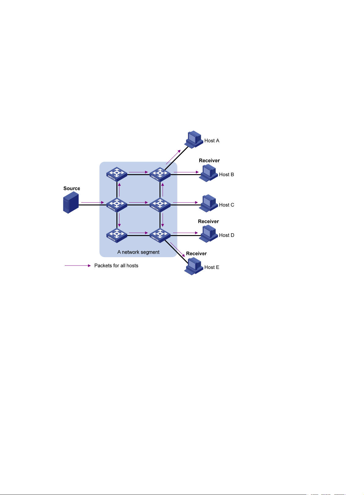
In broadcast transmission, the information source sends information to all hosts on the subnet, even if
some hosts do not need the information.
Figure 2 Broadcast transmission
Multicast
In Figure 2, assume that only Host B, Host D, and Host E need the information. If the information is
broadcast to the subnet, Host A and Host C also receive it. In addition to information security issues,
broadcasting to hosts that do not need the information also causes traffic flooding on the same subnet.
Broadcast is disadvantageous in transmitting data to specific hosts. Moreover, broadcast transmission is
a significant waste of network resources.
Unicast and broadcast techniques cannot provide point-to-multipoint data transmissions with the
minimum network consumption.
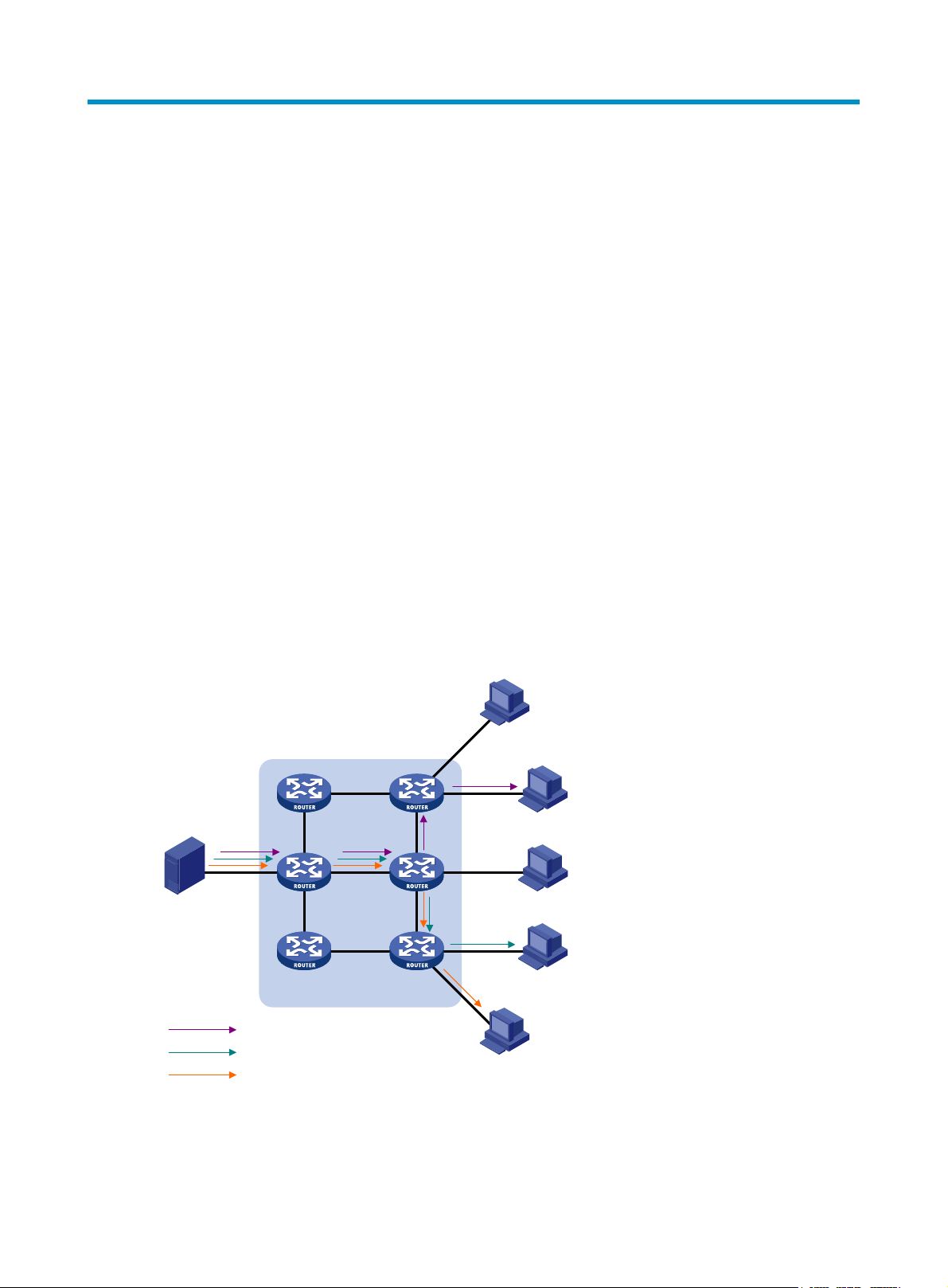
Multicast transmission can solve this problem. When some hosts on the network need multicast
information, the information sender, or multicast source, sends only one copy of the information.
Multicast distribution trees are built through multicast routing protocols, and the packets are replicated
only on nodes where the trees branch.
2
Page 8
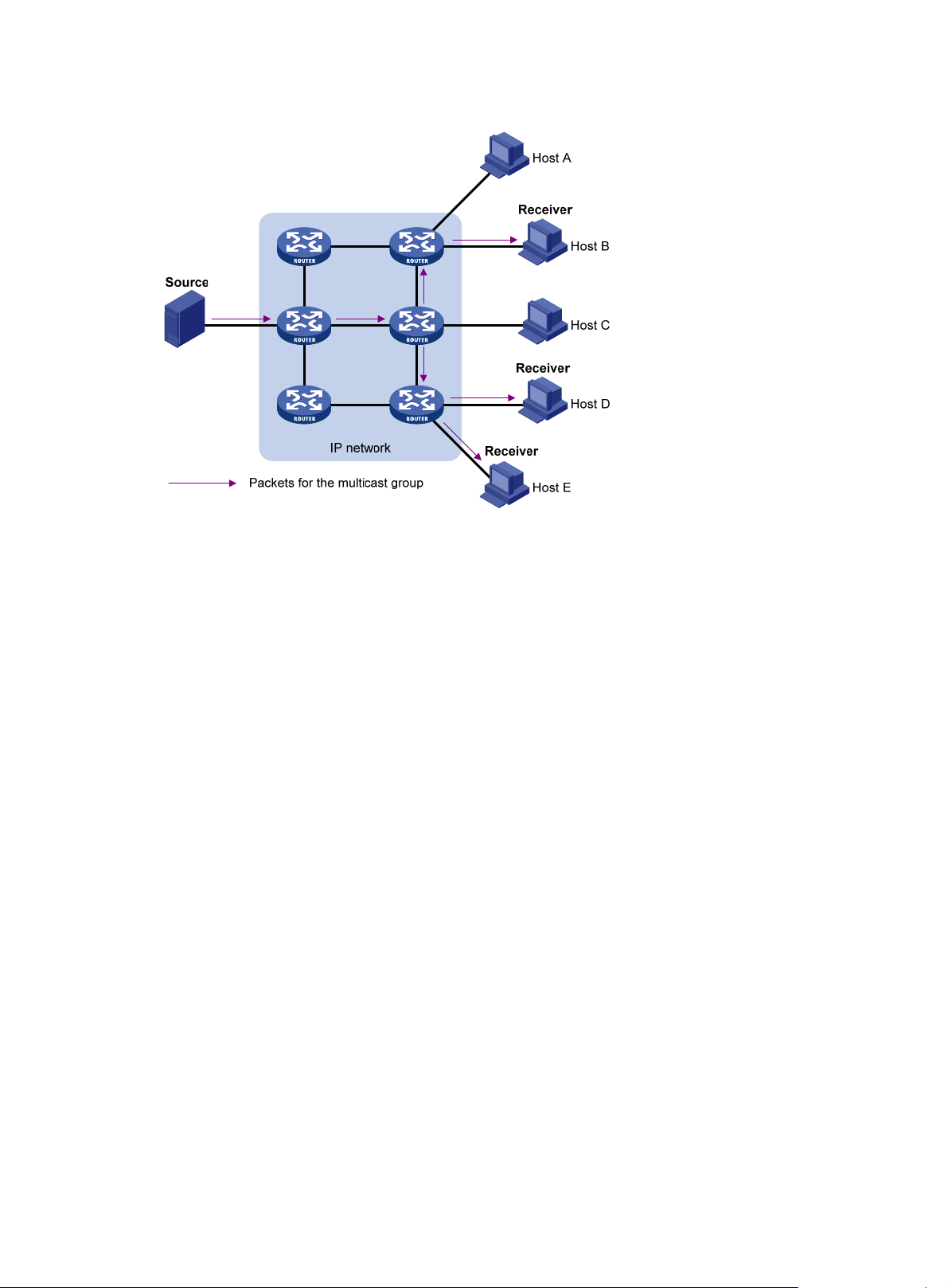
Figure 3 Multicast transmission
The mul ticast s ource sen ds only one co py of the inform ation to a mul ticast g ro up. Host B, Host D an d Host
E, which are receivers of the information, must join the multicast group. The routers on the network
duplicate and forward the information based on the distribution of the group members. Finally, the
information is correctly delivered to Host B, Host D, and Host E.
To summarize, multicast has the following advantages:
• Advantages over unicast—Because multicast traffic flows to the farthest-possible node from the
source before it is replicated and distributed, an increase in the number of hosts does not increase
the load of the source or remarkably add to the usage of network resources.
• Advantages over broadcast—Because multicast data is sent only to the receivers that need it,
multicast uses network bandwidth reasonably and enhances network security. In addition, data
broadcast is confined to the same subnet, but multicast is not.
Multicast features
• A multicast group is a multicast receiver set identified by an IP multicast address. Hosts join a
multicast group to become members of the multicast group before they can receive the multicast
data addressed to that multicast group. Typically, a multicast source does not need to join a
multicast group.
• An information sender is called a "multicast source". A multicast source can send data to multiple
multicast groups at the same time, and multiple multicast sources can send data to the same
multicast group at the same time.
• All hosts that have joined a multicast group become members of the multicast group. The group
memberships are dynamic. Hosts can join or leave multicast groups at any time. Multicast groups
are not subject to geographic restrictions.
• Routers or Layer 3 switches that support Layer 3 multicast are called "multicast routers" or "Layer 3
multicast devices". In addition to providing the multicast routing function, a multicast router can also
manage multicast group memberships on stub subnets with attached group members. A multicast
router itself can be a multicast group member.
3
Page 9

For a better understanding of the multicast concept, you can compare multicast transmission to the
transmission of TV programs.
Table 1 Comparing TV program transmission and multicast transmission
TV transmission
A TV station transmits a TV program through a
channel.
A user tunes the TV set to the channel. A receiver joins the multicast group.
The user starts to watch the TV program transmitted
by the TV station via the channel.
The user turns off the TV set or tunes to another
channel.
Common notations in multicast
The following notations are commonly used in multicast transmission:
• (*, G)—Indicates a rendezvous point tree (RPT), or a multicast packet that any multicast source sends
to multicast group G. Here, the asterisk represents any multicast source, and "G" represents a
specific multicast group.
• (S, G)—Indicates a shortest path tree (SPT), or a multicast packet that multicast source S sends to
multicast group G. Here, "S" represents a specific multicast source, and "G" represents a specific
multicast group.
Multicast transmission
A multicast source sends multicast data to a multicast
group.
The receiver starts to receive the multicast data that the
source is sending to the multicast group.
The receiver leaves the multicast group or joins another
group.
Multicast advantages and applications
Multicast advantages
Advantages of the multicast technique include the following:
• Enhanced efficiency—Reduces the processor load of information source servers and network
devices.
• Optimal performance—Reduces redundant traffic.
• Distributed application—Enables point-to-multipoint applications at the price of minimum network
resources.
Multicast applications
The scenarios in which the multicast technique can be effectively applied are:
• Multimedia and streaming applications, such as web TV, web radio, and real time video/audio
conferencing
• Communication for training and cooperative operations, such as distance learning and
telemedicine
• Data warehouse and financial applications (stock quotes)
• Any other point-to-multipoint application for data distribution
4
Page 10

Multicast models
Based on how the receivers treat the multicast sources, the multicast models include any-source multicast
(ASM), source-filtered multicast (SFM), and source-specific multicast (SSM).
ASM model
In the ASM model, any sender can send information to a multicast group as a multicast source, and
receivers can join a multicast group (identified by a group address) and obtain multicast information
addressed to that multicast group. In this model, receivers do not know the positions of the multicast
sources in advance. However, they can join or leave the multicast group at any time.
SFM model
The SFM model is derived from the ASM model. To a sender, the two models appear to have the same
multicast membership architecture.
The SFM model functionally extends the ASM model. The upper-layer software checks the source address
of received multicast packets and permits or denies multicast traffic from specific sources. Therefore,
receivers can receive the multicast data from only part of the multicast sources. To a receiver, multicast
sources are not all valid; they are filtered.
SSM model
Users might be interested in the multicast data from only certain multicast sources. The SSM model
provides a transmission service that enables users to specify the multicast sources that they are interested
in at the client side.
The main difference between the SSM model and the ASM model is that in the SSM model, receivers
have already determined the locations of the multicast sources by some other means. In addition, the
SSM model uses a multicast address range that is different from that of the ASM/SFM model, and
dedicated multicast forwarding paths are established between receivers and the specified multicast
sources.
Multicast architecture
IP multicast addresses the following questions:
• Where should the multicast source transmit information to? (Multicast addressing.)
• What receivers exist on the network? (Host registration.)
• Where is the multicast source that will provide data to the receivers? (Multicast source discovery.)
• How should information be transmitted to the receivers? (Multicast routing.)
IP multicast is an end-to-end service. The multicast architecture involves the following parts:
• Addressing mechanism—A multicast source sends information to a group of receivers through a
multicast address.
• Host registration—Receiver hosts can join and leave multicast groups dynamically. This mechanism
is the basis for management of group memberships.
• Multicast routing—A multicast distribution tree (a forwarding path tree for multicast data on the
network) is constructed for delivering multicast data from a multicast source to receivers.
• Multicast applications—A software system that supports multicast applications, such as video
conferencing, must be installed on multicast sources and receiver hosts. The TCP/IP stack must
support reception and transmission of multicast data.
5
Page 11

Multicast addresses
p
g
g
p
Network-layer multicast addresses (multicast IP addresses) enables communication between multicast
sources and multicast group members. In addition, a technique must be available to map multicast IP
addresses to link-layer multicast MAC addresses.
IP multicast addresses
• IPv4 multicast addresses
Internet Assigned Numbers Authority (IANA) assigned the Class D address space (224.0.0.0 to
239.255.255.255) to IPv4 multicast.
Table 2 Class D IP address blocks and description
Address block Descri
Reserved permanent group addresses. The IP address 224.0.0.0 is
reserved. Other IP addresses can be used by routing protocols and
224.0.0.0 to 224.0.0.255
224.0.1.0 to 238.255.255.255
for topology searching, protocol maintenance, and so on. Table 3
lists common permanent group addresses. A packet destined for an
address in this block will not be forwarded beyond the local subnet
regardless of the Time to Live (TTL) value in the IP header.
Globally scoped group addresses. This block includes the following
types of designated group addresses:
• 232.0.0.0/8—SSM group addresses.
tion
• 233.0.0.0/8—Glop group addresses.
Administratively scoped multicast addresses. These addresses are
239.0.0.0 to 239.255.255.255
considered locally unique rather than globally unique, and can be
reused in domains administered by different organizations without
causing conflicts. For more information, see RFC 2365.
NOTE:
"Glop" is a mechanism for assi
ning multicast addresses between different autonomous systems (ASs). By
filling an AS number into the middle two bytes of 233.0.0.0, you
For more information, see RFC 2770.
Table 3 Some reserved multicast addresses
et 255 multicast addresses for that AS.
Address Descri
224.0.0.1 All systems on this subnet, including hosts and routers
224.0.0.2 All multicast routers on this subnet
224.0.0.3 Unassigned
224.0.0.4 Distance Vector Multicast Routing Protocol (DVMRP) routers
224.0.0.5 Open Shortest Path First (OSPF) routers
224.0.0.6 OSPF designated routers and backup designated routers
224.0.0.7 Shared Tree (ST) routers
224.0.0.8 ST hosts
224.0.0.9 Routing Information Protocol version 2 (RIPv2) routers
224.0.0.11 Mobile agents
tion
6
Page 12
Address Description
p
224.0.0.12 Dynamic Host Configuration Protocol (DHCP) server/relay agent
224.0.0.13 All Protocol Independent Multicast (PIM) routers
224.0.0.14 Resource Reservation Protocol (RSVP) encapsulation
224.0.0.15 All Core-Based Tree (CBT) routers
224.0.0.16 Designated Subnetwork Bandwidth Management (SBM)
224.0.0.17 All SBMs
224.0.0.18 Virtual Router Redundancy Protocol (VRRP)
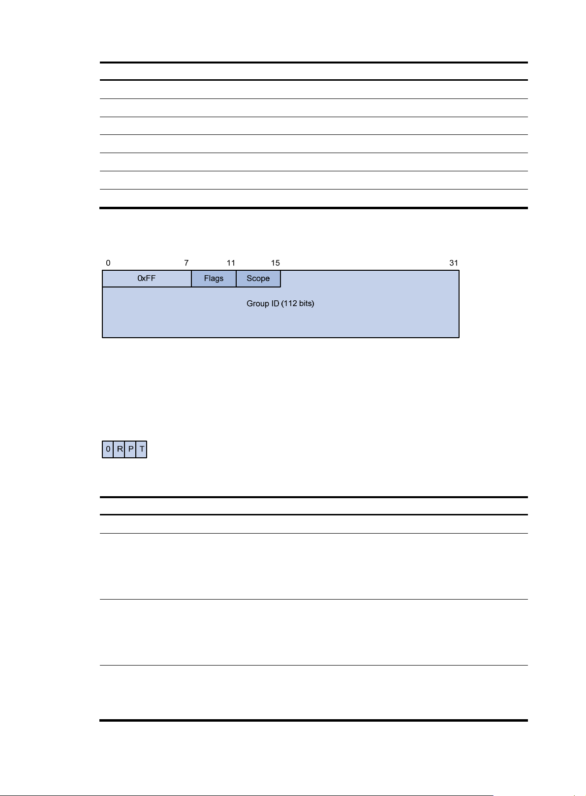
• IPv6 multicast addresses
Figure 4 IPv6 multicast format
The following describes the fields of an IPv6 multicast address:
{ 0xFF—The most significant eight bits are 11111111, which indicates that this address is an IPv6
multicast address.
{ Flags—The Flags field contains four bits.
Figure 5 Flags field format
Table 4 Flags field description
Bit Descri
0 Reserved, set to 0.
tion
• When set to 0, it indicates that this address is an IPv6 multicast
address without an embedded RP address.
R
• When set to 1, it indicates that this address is an IPv6 multicast
address with an embedded RP address. (The P and T bits must
also be set to 1.)
• When set to 0, it indicates that this address is an IPv6 multicast
address not based on a unicast prefix.
P
• When set to 1, it indicates that this address is an IPv6 multicast
address based on a unicast prefix. (The T bit must also be set to
1. )
• When set to 0, it indicates that this address is an IPv6 multicast
T
address permanently-assigned by IANA.
• When set to 1, it indicates that this address is a transient, or
dynamically assigned IPv6 multicast address.
7
Page 13
{ Scope—The Scope field contains four bits, which indicate the scope of the IPv6 internetwork for
g
which the multicast traffic is intended.
Table 5 Values of the Scope field
Value Meanin
0, F Reserved
1 Interface-local scope
2 Link-local scope
3 Subnet-local scope
4 Admin-local scope
5 Site-local scope
6, 7, 9 through D Unassigned
8 Organization-local scope
E Global scope
{ Group ID—The Group ID field contains 112 bits. It uniquely identifies an IPv6 mul tic ast group in
the scope that the Scope field defines.
Ethernet multicast MAC addresses
A multicast MAC address identifies a group of receivers at the data link layer.
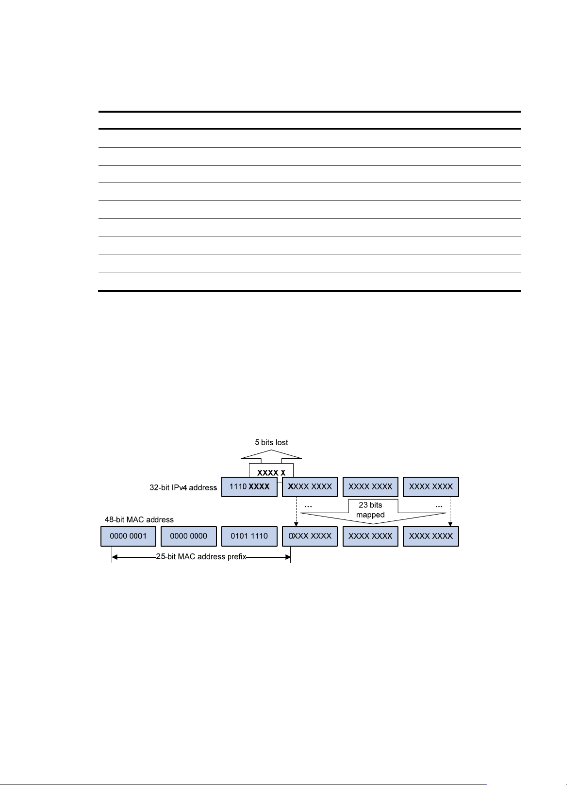
• IPv4 multicast MAC addresses
As defined by IANA, the most significant 24 bits of an IPv4 multicast MAC address are 0x01005E.
Bit 25 is 0, and the other 23 bits are the least significant 23 bits of a multicast IPv4 address.
Figure 6 IPv4-to-MAC address mapping
The most significant four bits of a multicast IPv4 address are 1110, which indicates that this
address is a multicast address. Only 23 bits of the remaining 28 bits are mapped to a MAC
address, so five bits of the multicast IPv4 address are lost. As a result, 32 multicast IPv4 addresses
map to the same IPv4 multicast MAC address. Therefore, in Layer 2 multicast forwarding, a switch
might receive some multicast data destined for other IPv4 multicast groups. The upper layer must
filter such redundant data.
• IPv6 multicast MAC addresses
The most significant 16 bits of an IPv6 multicast MAC address are 0x3333. The least significant
32 bits are the least significant 32 bits of a multicast IPv6 address.
8
Page 14
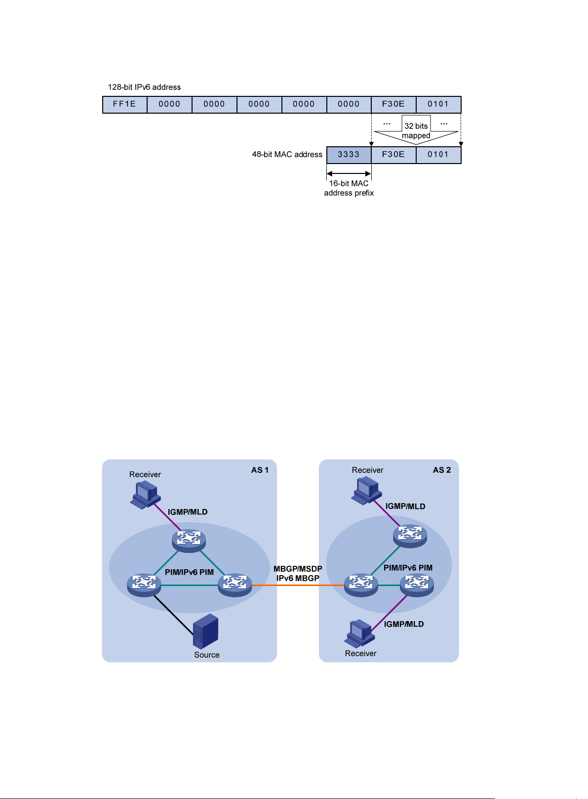
Figure 7 An example of IPv6-to-MAC address mapping
Multicast protocols
Generally, Layer 3 multicast refers to IP multicast working at the network layer. The corresponding
multicast protocols are Layer 3 multicast protocols, which include IGMP, MLD, PIM, IPv6 PIM, MSDP,
MBGP, and IPv6 MBGP. Layer 2 multicast refers to IP multicast working at the data link layer. The
corresponding multicast protocols are Layer 2 multicast protocols, which include IGMP snooping, MLD
snooping, PIM snooping, IPv6 PIM snooping, multicast VLAN, and IPv6 multicast VLAN.
IGMP snooping, PIM snooping, multicast VLAN, IGMP, PIM, MSDP, and MBGP are for IPv4, and MLD
snooping, IPv6 PIM snooping, IPv6 multicast VLAN, MLD, IPv6 PIM, and IPv6 MBGP are for IPv6.
This section provides only general descriptions about applications and functions of the Layer 2 and Layer
3 multicast protocols in a network. For more information about these protocols, see the related chapters.
Layer 3 multicast protocols
Layer 3 multicast protocols include multicast group management protocols and multicast routing
protocols.
Figure 8 Positions of Layer 3 multicast protocols
• Multicast group management protocols
Typically, the Internet Group Management Protocol (IGMP) or Multicast Listener Discovery Protocol
(MLD) is used between hosts and Layer 3 multicast devices that directly connect to the hosts. These
9
Page 15
protocols define the mechanism of establishing and maintaining group memberships between
hosts and Layer 3 multicast devices.
• Multicast routing protocols
A multicast routing protocol runs on Layer 3 multicast devices to establish and maintain multicast
routes and forward multicast packets correctly and efficiently. Multicast routes constitute loop-free
data transmission paths from a data source to multiple receivers, namely, a multicast distribution
tree.
In the ASM model, multicast routes include intra-domain routes and inter-domain routes.
{ An intra-domain multicast routing protocol discovers multicast sources and builds multicast
distribution trees within an AS to deliver multicast data to receivers. Among a variety of mature
intra-domain multicast routing protocols, Protocol Independent Multicast (PIM) is most widely
used. Based on the forwarding mechanism, PIM has dense mode (often referred to as
"PIM-DM"), and sparse mode (often referred to as "PIM-SM").
{ An inter-domain multicast routing protocol is used for delivery of multicast information between
two ASs. So far, mature solutions include Multicast Source Discovery Protocol (MSDP) and
Multicast Border Gateway Protocol (MBGP). MSDP propagates multicast source information
among different ASs. MBGP is an extension of the Multiprotocol Border Gateway Protocol
(MP-BGP) for exchanging multicast routing information among different ASs.
For the SSM model, multicast routes are not divided into intra-domain routes and inter-domain
routes. Because receivers know the position of the multicast source, channels established through
PIM-SM are sufficient for the transport of multicast information.
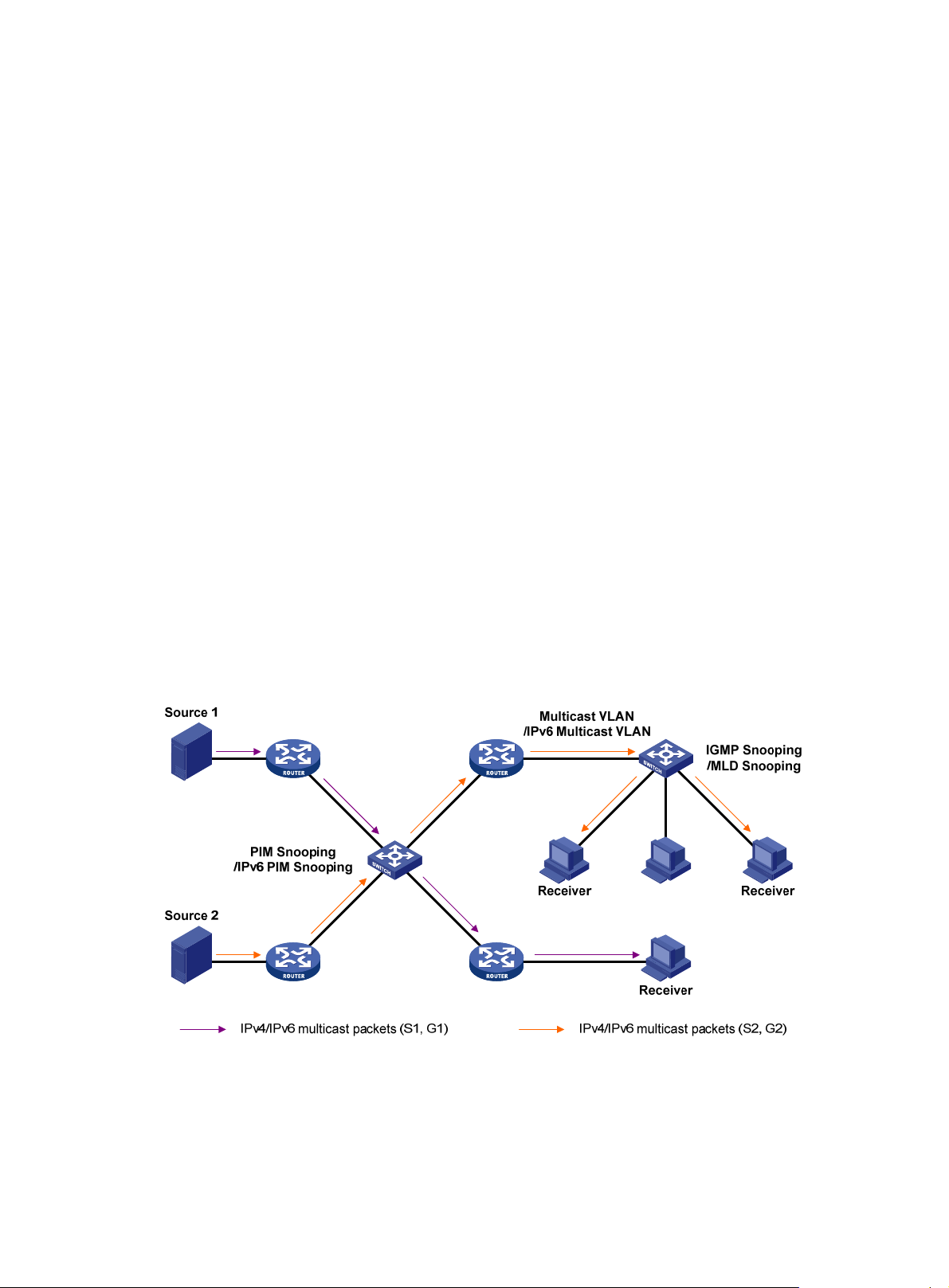
Layer 2 multicast protocols
Layer 2 multicast protocols include IGMP snooping, MLD snooping, PIM snooping, IPv6 PIM snooping,
multicast VLAN, and IPv6 multicast VLAN.
Figure 9 Positions of Layer 2 multicast protocols
• IGMP snooping and MLD snooping
IGMP snooping and MLD snooping are multicast constraining mechanisms that run on Layer 2
devices. They manage and control multicast groups by monitoring and analyzing IGMP or MLD
messages exchanged between the hosts and Layer 3 multicast devices, effectively controlling the
flooding of multicast data in a Layer 2 network.
10
Page 16

• PIM snooping and IPv6 PIM snooping
PIM snooping and IPv6 PIM snooping run on Layer 2 devices. They determine which ports are
interested in multicast data by analyzing the received IPv6 PIM messages, and add the ports to a
multicast forwarding entry to make sure that multicast data can be forwarded to only the ports that
are interested in the data.
• Multicast VLAN and IPv6 multicast VLAN
In the traditional multicast-on-demand mode, when users in different VLANs on a Layer 2 device
need multicast information, the upstream Layer 3 device must forward a separate copy of the
multicast data to each VLAN of the Layer 2 device. When the multicast VLAN or IPv6 multicast
VLAN feature is enabled on the Layer 2 device, the Layer 3 multicast device sends only one copy
of multicast to the multicast VLAN or IPv6 multicast VLAN on the Layer 2 device. This approach
avoids waste of network bandwidth and extra burden on the Layer 3 device.
Multicast packet forwarding mechanism
In a multicast model, a multicast source sends information to the host group identified by the multicast
group address in the destination address field of IP multicast packets. To deliver multicast packets to
receivers located at different positions of the network, multicast routers on the forwarding paths usually
need to forward multicast packets that an incoming interface receives to multiple outgoing interfaces.
Compared with a unicast model, a multicast model is more complex in the following aspects:
• To ensure multicast packet transmission in the network, unicast routing tables or multicast routing
tables (for example, the MBGP routing table) specially provided for multicast must be used as
guidance for multicast forwarding.
• To process the same multicast information from different peers received on different interfaces of the
same device, every multicast packet undergoes a reverse path forwarding (RPF) check on the
incoming interface. The result of the RPF check determines whether the packet will be forwarded or
discarded. The RPF check mechanism is the basis for most multicast routing protocols to implement
multicast forwarding.
11
Page 17
Configuring IGMP snooping
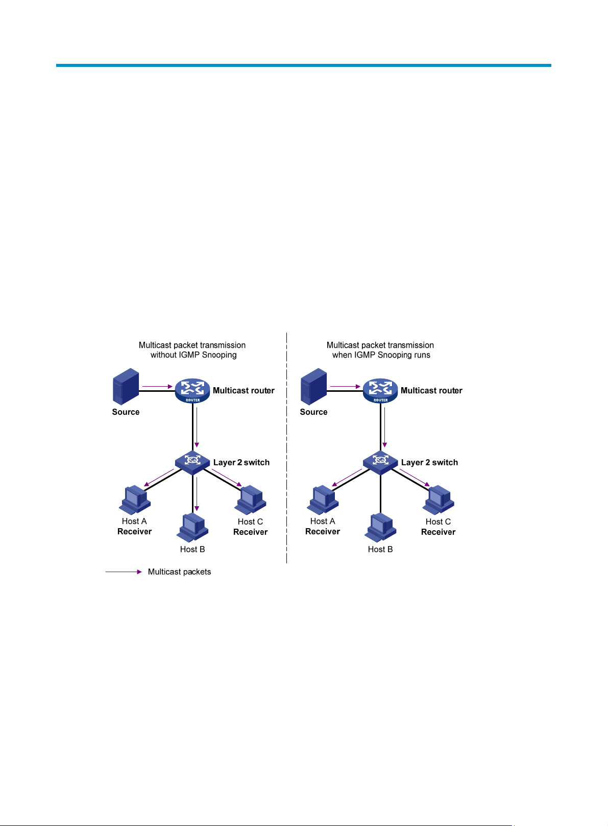
Overview
Internet Group Management Protocol (IGMP) snooping is a multicast constraining mechanism that runs
on Layer 2 devices to manage and control multicast groups.
By analyzing received IGMP messages, a Layer 2 device that runs IGMP snooping establishes mappings
between ports and multicast MAC addresses, and forwards multicast data based on these mappings.
As shown in Figure 10, w
all devices at Layer 2. With IGMP snooping enabled, the Layer 2 switch forwards multicast packets for
known multicast groups to only the receivers that require the multicast data at Layer 2. This feature
improves bandwidth efficiency, enhances multicast security, and helps per-host accounting for multicast
users.
Figure 10 Before and after IGMP snooping is enabled on the Layer 2 device
ithout IGMP snooping enabled, the Layer 2 switch floods multicast packets to
Basic concepts in IGMP snooping
IGMP snooping related ports
As shown in Figure 11, Router A connects to the multicast source, IGMP snooping runs on Switch A and
Switch B, and Host A and Host C are receiver hosts as members of a multicast group.
12
Page 18
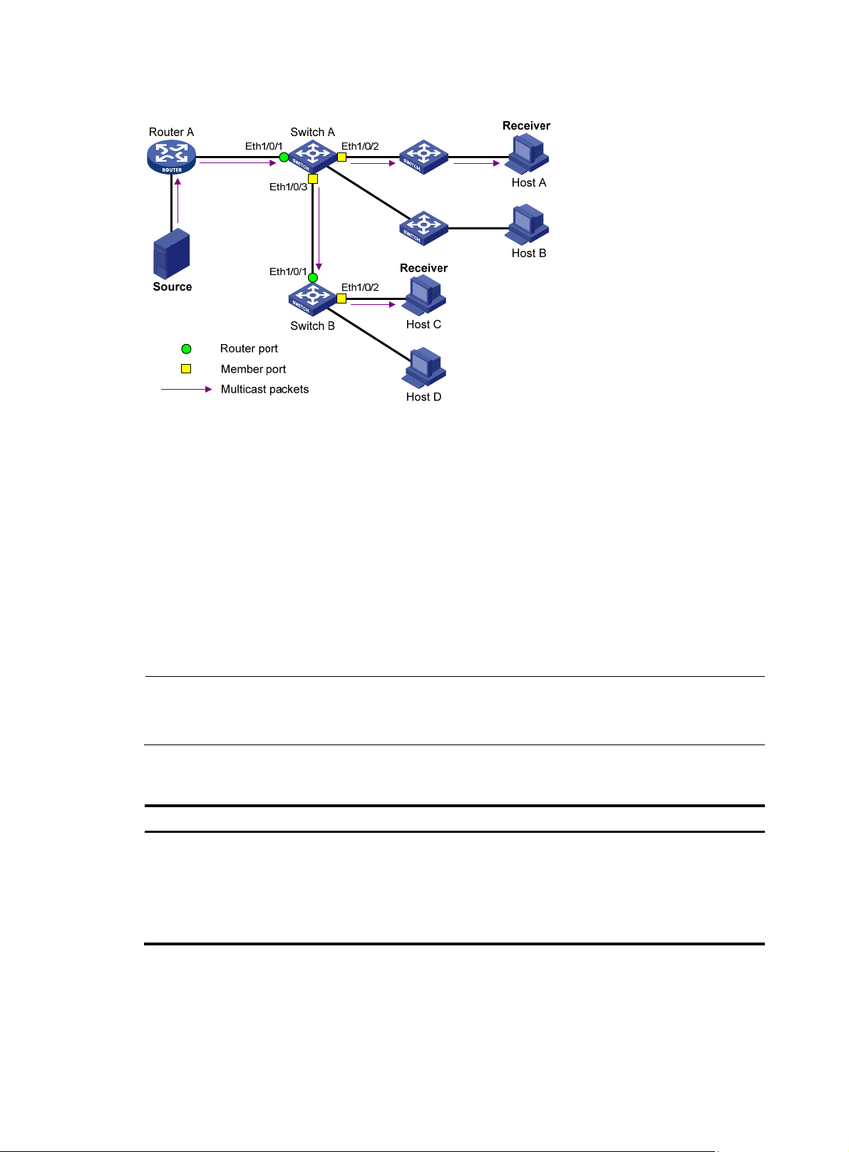
Figure 11 IGMP snooping related ports
A
y
The following describes the ports involved in IGMP snooping:
• Router port—Layer 3 multicast device-side port. Layer 3 multicast devices include designated
routers (DRs) and IGMP queriers. In Figure 11, Ether
net 1/0/1 of Switch A and Ethernet 1/0/1 of
Switch B are router ports. The switch registers all its router ports in its router port list.
Do not confuse the "router port" in IGMP snooping with the "routed interface" commonly known as
the "Layer 3 interface." The router port in IGMP snooping is the Layer 2 interface.
• Member port—Multicast receiver-side port. In Figure 11, Ether
net 1/0/2 and Ethernet 1/0/3 of
Switch A and Ethernet 1/0/2 of Switch B are member ports. The switch registers all its member
ports in its IGMP snooping forwarding table.
Unless otherwise specified, router ports and member ports in this document include both static and
dynamic router ports and member ports.
NOTE:
n IGMP-snooping-enabled switch deems that all its ports on which IGMP general queries with the source
IP address other than 0.0.0.0 or that receive PIM hello messages are received are dynamic router ports.
Aging timers for dynamic ports in IGMP snooping and related messages and actions
Timer Description
For each dynamic router
port, the switch starts an
Dynamic router port
aging timer
aging timer. When the
timer expires, the
dynamic router port ages
out.
Message before expiry Action after expir
IGMP general query of
which the source address
is not 0.0.0.0 or PIM
hello.
The switch removes this
port from its router port
list.
13
Page 19

Timer Description
y
When a port dynamically
joins a multicast group,
Dynamic member port
aging timer
the switch starts an aging
timer for the port. When
the timer expires, the
dynamic member port
ages out.
NOTE:
In IGMP snooping, only dynamic ports age out. Static ports never age out.
How IGMP snooping works
In this section, the involved ports are dynamic ports. For information about how to configure and remove
static ports, see "Configuring static ports."
A switch that runs IGMP snooping performs different actions when it receives different IGMP messages.
When receiving a general query
The IGMP querier periodically sends IGMP general queries to all hosts and routers identified by the
address 224.0.0.1 on the local subnet to determine whether any active multicast group members exist on
the subnet.
Message before expiry Action after expir
The switch removes this
IGMP membership
report.
port from the IGMP
snooping forwarding
table.
After receiving an IGMP general query, the switch forwards it to all ports in the VLAN, except the port
that received the query. The switch also performs one of the following actions:
• If the receiving port is a dynamic router port in the router port list, restarts the aging timer for the
port.
• If the receiving port is not in its router port list, adds it into its router port list as a dynamic router port
and starts an aging timer for the port.
When receiving a membership report
A host sends an IGMP report to the IGMP querier for the following purposes:
• If the host has been a member of a multicast group, responds to the query with an IGMP report.
• Applies for joining a multicast group.
After receiving an IGMP report, the switch forwards it through all the router ports in the VLAN, resolves
the address of the reported multicast group. The switch also performs one of the following actions:
• If no forwarding entry matches the group address, creates a forwarding entry for the group, adds
the receiving port as a dynamic member port to the forwarding entry, and starts an aging timer for
the port.
• If a forwarding entry matches the group address, but the receiving port is not in the forwarding
entry for the group, adds the port as a dynamic member port to the forwarding entry and starts an
aging timer for the port.
• If a forwarding entry matches the group address and the receiving port is in the forwarding entry
for the group, restarts the aging timer for the port.
A switch does not forward an IGMP report through a non-router port. If the switch forwards a report
message through a member port, the IGMP report suppression mechanism causes all the attached hosts
14
Page 20

that are monitoring the reported multicast address suppress their own reports. This makes the switch
unable to know whether the reported multicast group still has active members attached to that port.
When receiving a leave message
When an IGMPv 1 host leaves a mu ltic ast g ro up, th e hos t doe s not send an I GMP l eave m essag e, and the
switch cannot know immediately that the host has left the multicast group. However, because the host
stops sending IGMP reports as soon as it leaves the multicast group, the switch removes the port that
connects to the host from the forwarding entry for the multicast group when the aging timer for the port
expires.
When an IGMPv2 or IGMPv3 host leaves a multicast group, the host sends an IGMP leave message to
the multicast router.
When the switch receives an IGMP leave message on a dynamic member port, the switch first examines
whether a forwarding entry matches the group address in the message, and, if a match is found, whether
the forwarding entry for the group contains the dynamic member port.
• If no forwarding entry matches the group address, or if the forwarding entry does not contain the
port, the switch directly discards the IGMP leave message.
• If a forwarding entry matches the group address and the forwarding entry contains the port, the
switch forwards the leave message to all router ports in the VLAN. Because the switch does not
know whether any other hosts attached to the port are still listening to that group address, the switch
does not immediately remove the port from the forwarding entry for that group. Instead, it restarts
the aging timer for the port.
After receiving the IGMP leave message, the IGMP querier resolves the multicast group address in the
message and sends an IGMP group-specific query to the multicast group through the port that received
the leave message. After receiving the IGMP group-specific query, the switch forwards it through all its
router ports in the VLAN and all member ports of the multicast group. The switch also performs the
following judgment for the port that received the IGMP leave message:
• If the port (assuming that it is a dynamic member port) receives an IGMP report in response to the
group-specific query before its aging timer expires, it indicates that some host attached to the port
is receiving or expecting to receive multicast data for the multicast group. The switch restarts the
aging timer for the port.
• If the port receives no IGMP report in response to the group-specific query before its aging timer
expires, it indicates that no hosts attached to the port are still listening to that group address. The
switch removes the port from the forwarding entry for the multicast group when the aging timer
expires.
IGMP snooping proxying
You can configure the IGMP snooping proxying function on an edge device to reduce the number of
IGMP reports and leave messages sent to its upstream device. The device configured with IGMP
snooping proxying is called an IGMP snooping proxy. It is a host from the perspective of its upstream
device.
Even though an IGMP snooping proxy is a host from the perspective of its upstream device, the IGMP
membership report suppression mechanism for hosts does not take effect on it.
15
Page 21
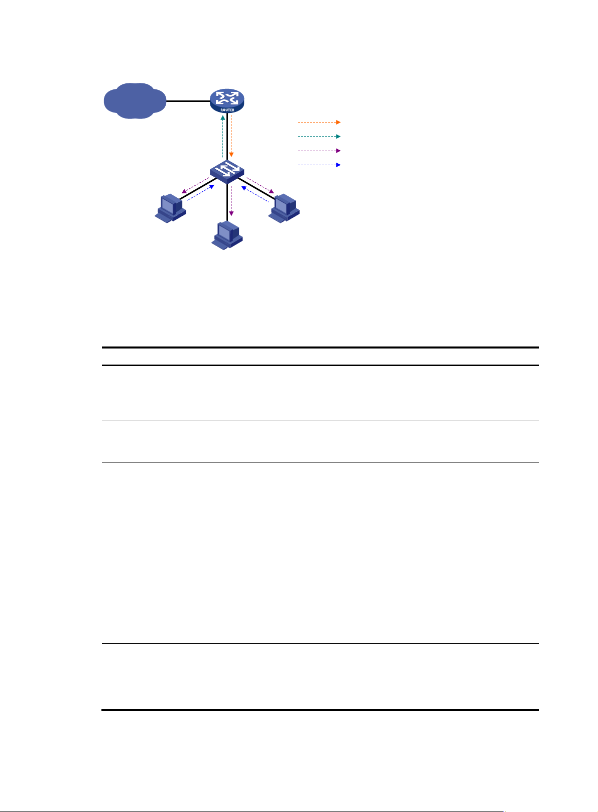
Figure 12 Network diagram
g
IP network
Proxy & Querier
Switch A
Host A
Receiver
Host B
IGMP Querier
Router A
Query from Router A
Report from Switch A
Query from Switch A
Report from Host
Host C
Receiver
As shown in Figure 12, Swi tch A works as an IGMP snooping proxy. As a host from the perspective of the
querier Router A, Switch A represents its attached hosts to send membership reports and leave messages
to Router A.
Table 6 IGMP message processing on an IGMP snooping proxy
IGMP messa
General query
e Actions
When receiving an IGMP general query, the proxy forwards it to all
ports but the receiving port. In addition, the proxy generates a report
according to the group memberships it maintains and sends the report
out of all router ports.
Group-specific query
Report
Leave
In response to the IGMP group-specific query for a certain multicast
group, the proxy sends the report to the group out of all router ports if the
forwarding entry for the group still contains a member port.
After receiving a report for a multicast group, the proxy looks up the
multicast forwarding table for the forwarding entry for the multicast
group.
• If a forwarding entry matches the multicast group and contains the
receiving port as a dynamic member port, the proxy restarts the
aging timer for the port.
• If a forwarding entry matches the multicast group but does not
contain the receiving port, the proxy adds the port to the forwarding
entry as a dynamic member port and starts an aging timer for the
port.
• If no forwarding entry matches the multicast group, the proxy creates
a forwarding entry for the multicast group, adds the receiving port to
the forwarding entry as a dynamic member port, and starts an aging
timer for the port.
In response to an IGMP leave message for a multicast group, the proxy
sends a group-specific query out of the receiving port. After making sure
that no member port is contained in the forwarding entry for the
multicast group, the proxy sends a leave message to the group out of all
router ports.
16
Page 22

Protocols and standards
RFC 4541, Considerations for Internet Group Management Protocol (IGMP) and Multicast Listener
Discovery (MLD) Snooping Switches
IGMP snooping configuration task list
Task Remarks
Configuring basic
IGMP snooping
functions
Configuring IGMP
snooping port
functions
Configuring IGMP
snooping querier
Configuring IGMP
snooping proxying
Enabling IGMP snooping Required
Specifying the version of IGMP snooping Optional
Configuring static multicast MAC address entries Optional
Setting aging timers for dynamic ports Optional
Configuring static ports Optional
Configuring a port as a simulated member host Optional
Enabling IGMP snooping fast-leave processing Optional
Disabling a port from becoming a dynamic router port Optional
Enabling IGMP snooping querier Optional
Configuring parameters for IGMP queries and responses Optional
Configuring the source IP addresses for IGMP queries Optional
Enabling IGMP snooping proxying Optional
Configuring a source IP address for the IGMP messages sent by
the proxy
Configuring a multicast group filter Optional
Configuring multicast source port filtering Optional
Enabling dropping unknown multicast data Optional
Optional
Configuring IGMP report suppression Optional
Configuring an IGMP
snooping policy
Setting the maximum number of multicast groups that a port
can join
Setting the 802.1p precedence for IGMP messages Optional
Enabling multicast group replacement Optional
Configuring a multicast user control policy (available only on
the HP 3100 v2 EI)
Enabling the IGMP snooping host tracking function Optional
Setting the DSCP value for IGMP messages Optional
Optional
Optional
For the configuration tasks in this section:
• In IGMP snooping view, the configurations that you make are effective in all VLANs. In VLAN view,
the configurations that you make are effective on only the ports that belong to the current VLAN. For
a given VLAN, a configuration that you make in IGMP snooping view is effective only if you do not
make the same configuration in VLAN view.
17
Page 23

• In IGMP snooping view, the configurations that you make are effective on all ports. In Layer 2
Ethernet interface view or Layer 2 aggregate interface view, the configurations that you make are
effective only on the current port. In port group view, the configurations that you make are effective
on all ports in the current port group. For a given port, a configuration that you make in IGMP
snooping view is effective only if you do not make the same configuration in Layer 2 Ethernet
interface view, Layer 2 aggregate interface view, or port group view.
• For IGMP snooping, the configurations that you make on a Layer 2 aggregate interface do not
interfere with those you make on its member ports, nor do they participate in aggregation
calculations. Configurations that you make on a member port of an aggregate group do not take
effect until it leaves the aggregate group.
Configuring basic IGMP snooping functions
Before you configure basic IGMP snooping functions, complete the following tasks:
• Configure the corresponding VLANs.
• Determine the version of IGMP snooping.
Enabling IGMP snooping
When you enable IGMP snooping, follow these guidelines:
• You must enable IGMP snooping globally before you enable it in a VLAN.
• When you enable IGMP snooping in a specified VLAN, IGMP snooping works only on the ports in
this VLAN.
To enable IGMP snooping:
Step Command
1. Enter system view.
2. Enable IGMP snooping globally
and enter IGMP-snooping view.
3. Return to system view.
4. Enter VLAN view.
5. Enable IGMP snooping in the
VLAN.
system-view N/A
igmp-snooping Disabled by default
quit N/A
vlan vlan-id N/A
igmp-snooping enable
Specifying the version of IGMP snooping
Different versions of IGMP snooping can process different versions of IGMP messages:
• IGMPv2 snooping can process IGMPv1 and IGMPv2 messages, but cannot process IGMPv3
messages, which will be flooded in the VLAN.
• IGMPv3 snooping can process IGMPv1, IGMPv2 and IGMPv3 messages.
Remarks
Disabled by default
If you change IGMPv3 snooping to IGMPv2 snooping, the system:
• Clears all IGMP snooping forwarding entries that are dynamically added.
• Keeps static IGMPv3 snooping forwarding entries (*, G).
18
Page 24

• Clears static IGMPv3 snooping forwarding entries (S, G), which will be restored when IGMP
snooping is switched back to IGMPv3 snooping.
For more information about static joins, see "Configuring static ports."
To specify the version of IGMP snooping:
Step Command
1. Enter system view.
2. Enter VLAN view.
3. Specify the version of IGMP
snooping.
system-view N/A
vlan vlan-id N/A
igmp-snooping version
version-number
Remarks
Version 2 by default
Configuring static multicast MAC address entries
In Layer-2 multicast, a Layer 2 multicast protocol (such as IGMP snooping) can dynamically add multicast
MAC address entries. Or, you can manually configure multicast MAC address entries.
Configuration guidelines
• In system view, the configuration is effective for the specified ports. In interface view or port group
view, the configuration is effective only on the current port or the ports in the current port group.
• Any legal multicast MAC address except 0100-5Exx-xxxx (where "x" represents a hexadecimal
number from 0 to F) can be manually added to the multicast MAC address table. Multicast MAC
addresses are the MAC addresses whose the least significant bit of the most significant octet is 1.
Configuration procedure
To configure a static multicast MAC address entry in system view:
Step Command
1. Enter system view.
2. Configure a static multicast
MAC address entry.
To configure static multicast MAC address entries in interface view:
Step Command
1. Enter system view.
2. Enter Layer 2 Ethernet
interface view, Layer 2
aggregate interface view, or
port group view.
Remarks
system-view N/A
mac-address multicast
mac-address interface interface-list
vlan vlan-id
No static multicast MAC address
entries exist by default.
Remarks
system-view N/A
• Enter Layer 2 Ethernet interface
view or Layer 2 aggregate
interface view:
interface interface-type
interface-number
Use either command.
• Enter port group view:
port-group manual
port-group-name
3. Configure a static multicast
MAC address entry.
mac-address multicast
mac-address vlan vlan-id
19
No static multicast MAC address
entries exist by default.
Page 25

Configuring IGMP snooping port functions
Before you configure IGMP snooping port functions, complete the following tasks:
• Enable IGMP snooping in the VLAN.
• Configure the corresponding port groups.
• Determine the aging time of dynamic router ports.
• Determine the aging time of dynamic member ports.
• Determine the multicast group and multicast source addresses.
Setting aging timers for dynamic ports
If a switch receives no IGMP general queries or PIM hello messages on a dynamic router port when the
aging timer of the port expires, the switch removes the port from the router port list.
If the switch receives no IGMP reports for a multicast group on a dynamic member port when the aging
timer of the port expires, the switch removes the port from the multicast forwarding entry for that multicast
group.
If the memberships of multicast groups change frequently, you can set a relatively small value for the
aging timer of the dynamic member ports. If the memberships of multicast groups change rarely, you can
set a relatively large value.
Configuring aging timers for dynamic ports globally
Step Command
1. Enter system view.
2. Enter IGMP-snooping view.
3. Set the aging timer for
dynamic router ports.
4. Set the aging timer for
dynamic member ports.
system-view N/A
igmp-snooping N/A
router-aging-time interval
host-aging-time interval
Configuring aging timers for dynamic ports in a VLAN
Step Command
1. Enter system view.
2. Enter VLAN view.
3. Set the aging timer for
dynamic router ports.
4. Set the aging timer for
dynamic member ports.
system-view N/A
vlan vlan-id N/A
igmp-snooping router-aging-time
interval
igmp-snooping host-aging-time
interval
Remarks
105 seconds by default
260 seconds by default
Remarks
105 seconds by default
260 seconds by default
20
Page 26

Configuring static ports
If all hosts attached to a port are interested in the multicast data addressed to a particular multicast group
or the multicast data that a particular multicast source sends to a particular group, you can configure the
port as a static member port for the specified multicast group or the specified multicast source and group.
You can also configure a port as a static router port, through which the switch can forward all the
multicast traffic that it received.
Configuration guidelines
• A static member port does not respond to queries from the IGMP querier; when you configure a port
as a static member port or cancel this configuration on the port, the port does not send an
unsolicited IGMP report or an IGMP leave message.
• Static member ports and static router ports never age out. To remove such a port, use the
corresponding undo command.
Configuration procedure
To configure static ports:
Step Command
1. Enter system view.
system-view N/A
Remarks
• Enter Layer 2 Ethernet interface
view or Layer 2 aggregate
2. Enter Layer 2 Ethernet
interface view, Layer 2
aggregate interface view, or
port group view.
3. Configure the port as a static
member port.
4. Configure the port as a static
router port.
interface view:
interface interface-type
interface-number
• Enter port group view:
port-group manual
port-group-name
igmp-snooping static-group
group-address [ source-ip
source-address ] vlan vlan-id
igmp-snooping static-router-port
vlan vlan-id
Use either command.
No static member ports exist by
default.
No static router ports exist by
default.
Configuring a port as a simulated member host
Generally, a host t hat runs I GM P can respond to IGMP queries that the IGM P querier sends. If a host fails
to respond, the multicast router might deem that no member of this multicast group exists on the network
segment, and removes the corresponding forwarding path.
To avoid this situation, you can configure the port as a simulated member host for a multicast group. A
simulated host is equivalent to an independent host. For example, when a simulated member host
receives an IGMP query, it gives a response separately. Therefore, the switch can continue receiving
multicast data.
A simulated host acts like a real host in the following ways:
• When a port is configured as a simulated member host, the switch sends an unsolicited IGMP
report through the port, and can respond to IGMP general queries with IGMP reports through the
port.
21
Page 27

• When the simulated joining function is disabled on a port, the switch sends an IGMP leave
message through the port.
Unlike a static member port, a port that you configure as a simulated member host ages out like a
dynamic member port.
To configure a port as a simulated member host:
Step Command
1. Enter system view.
system-view N/A
Remarks
• Enter Layer 2 Ethernet interface
view or Layer 2 aggregate
2. Enter Layer 2 Ethernet
interface view, Layer 2
aggregate interface view, or
port group view.
3. Configure a port as a
simulated member host.
interface view:
interface interface-type
interface-number
• Enter port group view:
port-group manual
port-group-name
igmp-snooping host-join
group-address [ source-ip
source-address ] vlan vlan-id
Use either command.
Not configured by default.
Enabling IGMP snooping fast-leave processing
IGMP snooping fast-leave processing enables the switch to process IGMP leave messages quickly. With
IGMP snooping fast-leave processing enabled, when the switch receives an IGMP leave message on a
port, it immediately removes that port from the forwarding entry for the multicast group specified in the
message. Then, when the switch receive s IGMP group-specific queries for th at multicast group, it does not
forward them to that port.
On a port that has only one host attached, you can enable IGMP snooping fast-leave processing to save
bandwidth and resources. However, on a port that has multiple hosts attached, you should not enable
IGMP snooping fast-leave processing if you have enabled dropping unknown multicast data globally or
for the port. Otherwise, if a host on the port leaves a multicast group, the other hosts attached to the port
in the same multicast group cannot receive the multicast data for the group.
Enabling IGMP snooping fast-leave processing globally
Step Command
1. Enter system view.
2. Enter IGMP-snooping view.
3. Enable IGMP snooping
fast-leave processing.
system-view N/A
igmp-snooping N/A
fast-leave [ vlan vlan-list ] Disabled by default
Enabling IGMP snooping fast-leave processing on a port
Step Command
1. Enter system view.
system-view N/A
Remarks
Remarks
22
Page 28

Step Command
• Enter Layer 2 Ethernet interface
view or Layer 2 aggregate
2. Enter Layer 2 Ethernet
interface view, Layer 2
aggregate interface view, or
port group view.
interface view:
interface interface-type
interface-number
• Enter port group view:
port-group manual
port-group-name
Remarks
Use either command.
3. Enable IGMP snooping
fast-leave processing.
igmp-snooping fast-leave [ vlan
vlan-list ]
Disabled by default.
Disabling a port from becoming a dynamic router port
The following problems might exist in a multicast access network:
• After receiving an IGMP general query or a PIM hello message from a connected host, a router port
becomes a dynamic router port. Before its timer expires, this dynamic router port receives all
multicast packets within the VLAN where the port belongs, and forwards them to the host, affecting
normal multicast reception of the host.
• In addition, the IGMP general query or PIM hello message that the host sends affects the multicast
routing protocol state on Layer 3 devices, such as the IGMP querier or DR election, and might
further cause network interruption.
To solve these problems, disable that router port from becoming a dynamic router port after the port
receives an IGMP general query or a PIM hello message, so as to improve network security and control
over multicast users.
To disable a port from becoming a dynamic router port:
Step Command
1. Enter system view.
system-view N/A
Remarks
• Enter Layer 2 Ethernet interface
view or Layer 2 aggregate
2. Enter Layer 2 Ethernet
interface view, Layer 2
aggregate interface view, or
port group view.
3. Disable the ports from
becoming dynamic router
port.
interface view:
interface interface-type
interface-number
• Enter port group view:
port-group manual
port-group-name
igmp-snooping router-port-deny
[ vlan vlan-list ]
Use either command.
By default, a port can become a
dynamic router port.
NOTE:
This configuration does not affect the static router port configuration.
23
Page 29

Configuring IGMP snooping querier
g
Before you configure IGMP snooping querier, complete the following tasks:
• Enable IGMP snooping in the VLAN.
• Determine the IGMP general query interval.
• Determine the IGMP last-member query interval.
• Determine the maximum response delay for IGMP general queries.
• Determine the source address of IGMP general queries.
• Determine the source address of IGMP group-specific queries.
Enabling IGMP snooping querier
In an IP multicast network that runs IGMP, a multicast router or Layer 3 multicast switch sends IGMP
queries, so that all Layer 3 multicast devices can establish and maintain multicast forwarding entries, in
order to forward multicast traffic correctly at the network layer. This router or Layer 3 switch is called the
"IGMP querier."
However, a Layer 2 multicast switch does not support IGMP, and therefore cannot send general queries
by default. When you enable IGMP snooping querier on a Layer 2 switch in a VLAN where multicast
traffic is switched only at Layer 2 and no multicast routers are present, the Layer 2 switch sends IGMP
queries, so that multicast forwarding entries can be established and maintained at the data link layer.
To enable IGMP snooping querier:
Step Command Remarks
1. Enter system view.
2. Enter VLAN view.
3. Enable IGMP snooping
querier.
IMPORTANT:
system-view N/A
vlan vlan-id N/A
igmp-snooping querier
Disabled by default
In a multicast network that runs IGMP, you do not need to configure an IGMP snooping querier because
it may affect IGMP querier elections by sending IGMP general queries with a low source IP address.
Configuring parameters for IGMP queries and responses
CAUTION:
In the confi
delay for IGMP general queries. Otherwise, multicast group members might be deleted by mistake.
You can modify the IGMP general query interval based on actual condition of the network.
uration, make sure that the IGMP general query interval is larger than the maximum response
A multicast listening host starts a timer for each multicast group that it has joined when it receives an
IGMP query (general query or group-specific query). This timer is initialized to a random value in the
range of 0 to the maximum response delay advertised in the IGMP query message. When the timer value
decreases to 0, the host sends an IGMP report to the multicast group.
24
Page 30

To speed up the response of hosts to IGMP queries and avoid simultaneous timer expirations causing
IGMP report traffic bursts, you must properly set the maximum response delay.
• The maximum response delay for IGMP general queries is set by the max-response-time command.
• The maximum response delay for IGMP group-specific queries equals the IGMP last-member query
interval.
Configuring the global parameters for IGMP queries and responses
Step Command
1. Enter system view.
2. Enter IGMP-snooping view.
3. Set the maximum response
delay for IGMP general
queries.
4. Set the IGMP last-member
query interval.
system-view N/A
igmp-snooping N/A
max-response-time interval 10 seconds by default
last-member-query-interval interval
Configuring the parameters for IGMP queries and responses in a VLAN
Step Command
1. Enter system view.
2. Enter VLAN view.
3. Set the interval for sending
IGMP general queries.
4. Set the maximum response
delay for IGMP general
queries.
5. Set the IGMP last-member
query interval.
system-view N/A
vlan vlan-id N/A
igmp-snooping query-interval interval 60 seconds by default
igmp-snooping max-response-time interval
igmp-snooping
last-member-query-interval interval
Remarks
1 second by default
Remarks
10 seconds by default
1 second by default
Configuring the source IP addresses for IGMP queries
After the switch receives an IGMP query whose source IP address is 0.0.0.0 on a port, it does not enlist
that port as a dynamic router port. This might prevent multicast forwarding entries from being correctly
created at the data link layer and eventually cause multicast traffic forwarding to fail. To avoid this
problem, when a Layer 2 switch acts as the IGMP snooping querier, HP recommends you to configure a
non-all-zero IP address as the source IP address of IGMP queries.
IMPORTANT:
The source address of IGMP query messages might affect the IGMP querier election within the segment
To configure the source IP addresses for IGMP queries:
Step Command
1. Enter system view.
system-view N/A
25
Remarks
Page 31

Step Command
2. Enter VLAN view.
vlan vlan-id N/A
Remarks
3. Configure the source address
of IGMP general queries.
4. Configure the source IP
address of IGMP
group-specific queries.
igmp-snooping general-query source-ip
{ ip-address | current-interface }
igmp-snooping special-query source-ip
{ ip-address | current-interface }
Configuring IGMP snooping proxying
Before you configure IGMP snooping proxying in a VLAN, complete the following tasks:
• Enable IGMP snooping in the VLAN.
• Determine the source IP address for the IGMP reports sent by the proxy.
• Determine the source IP address for the IGMP leave messages sent by the proxy.
Enabling IGMP snooping proxying
The IGMP snooping proxying function works on a per-VLAN basis. After you enable the function in a
VLAN, the device works as the IGMP snooping proxy for the downstream hosts and upstream router in
the VLAN.
To enable IGMP snooping proxying in a VLAN:
0.0.0.0 by default
0.0.0.0 by default
Step Command
1. Enter system view.
2. Enter VLAN view.
3. Enable IGMP snooping
proxying in the VLAN.
system-view N/A
vlan vlan-id N/A
igmp-snooping proxying enable Disabled by default
Remarks
Configuring a source IP address for the IGMP messages sent by the proxy
You can set the source IP addresses in the IGMP reports and leave messages that the IGMP snooping
proxy sends on behalf of its attached hosts.
To configure the source IP addresses for the IGMP messages that the IGMP snooping proxy sends on
behalf of its attached hosts in a VLAN:
Step Command
1. Enter system view.
2. Enter VLAN view.
3. Configure a source IP
address for the IGMP
reports that the proxy sends.
system-view
vlan vlan-id N/A
igmp-snooping report source-ip
{ ip-address | current-interface }
Remarks
N/A
The default is 0.0.0.0.
26
Page 32

Step Command
4. Configure a source IP
address for the IGMP leave
messages that the proxy
sends.
igmp-snooping leave source-ip
{ ip-address | current-interface }
Remarks
The default is 0.0.0.0.
Configuring an IGMP snooping policy
Before you configure an IGMP snooping policy, complete the following tasks:
• Enable IGMP snooping in the VLAN.
• Determine the ACL rule for multicast group filtering.
• Determine the maximum number of multicast groups that a port can join.
• Determine the 802.1p precedence for IGMP messages.
Configuring a multicast group filter
On an IGMP snooping–enabled switch, you can configure a multicast group filter to limit multicast
programs available to users.
In an application, when a user requests a multicast program, the user’s host initiates an IGMP report.
After receiving this report message, the switch resolves the multicast group address in the report and
looks up the ACL. If a match is found to permit the port that received the report to join the multicast group,
the switch creates an IGMP snooping forwarding entry for the multicast group and adds the port to the
forwarding entry. Otherwise, the switch drops this report message, in which case, the multicast data for
the multicast group is not sent to this port, and the user cannot retrieve the program.
Configuration guidelines
When you configure a multicast group filter in a multicast VLAN, be sure to configure the filter in the
sub-VLANs of the multicast VLAN. Otherwise, the configuration does not take effect.
Configuration procedure
To configure a multicast group filter globally:
Step Command
1. Enter system view.
2. Enter IGMP-snooping view.
3. Configure a multicast group
filter.
To configure a multicast group filter on a port:
Step Command
1. Enter system view.
Remarks
system-view N/A
igmp-snooping N/A
By default, no group filter is
group-policy acl-number [ vlan
vlan-list ]
globally configured. That is, the
hosts in a VLAN can join any valid
multicast group.
Remarks
system-view N/A
27
Page 33

Step Command
• Enter Layer 2 Ethernet interface
view or Layer 2 aggregate
2. Enter Layer 2 Ethernet
interface view, Layer 2
aggregate interface view, or
port group view.
3. Configure a multicast group
filter.
interface view:
interface interface-type
interface-number
• Enter port group view:
port-group manual
port-group-name
igmp-snooping group-policy
acl-number [ vlan vlan-list ]
Configuring multicast source port filtering
When the multicast source port filtering feature is enabled on a port, the port can connect to only
multicast receivers rather than to multicast sources, because the port blocks all multicast data packets but
it permits multicast protocol packets to pass.
If this feature is disabled on a port, the port can connect to both multicast sources and multicast receivers.
Remarks
Use either command.
By default, no group filter is
configured on the current port. That
is, the hosts on this port can join
any valid multicast group.
Configuring multicast source port filtering globally
Step Command
1. Enter system view.
2. Enter IGMP-snooping view.
3. Enable multicast source port
filtering.
system-view N/A
igmp-snooping N/A
source-deny port interface-list Disabled by default
Configuring multicast source port filtering on a port
Step Command
1. Enter system view.
2. Enter Layer 2 Ethernet
interface view or port group
view.
system-view N/A
• Enter Layer 2 Ethernet interface
view:
interface interface-type
interface-number
• Enter port group view:
port-group manual
port-group-name
Remarks
Remarks
Use either command.
3. Enable multicast source port
filtering.
igmp-snooping source-deny Disabled by default.
28
Page 34

Enabling dropping unknown multicast data
g g
Unknown multicast data refers to multicast data for which no entries exist in the IGMP snooping
forwarding table. When the switch receives such multicast traffic, one of the following occurs:
• When the function of dropping unknown multicast data is disabled, the switch floods unknown
multicast data in the VLAN that the unknown multicast data belongs to, causing network bandwidth
waste and low forwarding efficiency.
• When the function of dropping unknown multicast data is enabled, the switch forwards unknown
multicast data to its router ports instead of flooding it in the VLAN. If no router ports exist, the switch
drops the unknown multicast data.
Configuration procedure
To enable dropping unknown multicast data globally:
Step Command
1. Enter system view.
2. Enter IGMP-snooping view.
3. Enable dropping unknown
multicast data.
system-view N/A
igmp-snooping N/A
drop-unknown Disabled by default
Configuring IGMP report suppression
When a Layer 2 switch receives an IGMP report from a multicast group member, the switch forwards the
message to the Layer 3 device that directly connects to the Layer 2 switch. When multiple members of a
multicast group are attached to the Layer 2 switch, the Layer 3 device might receive duplicate IGMP
reports for the multicast group from these members.
With the IGMP report suppression function enabled, within each query interval, the Layer 2 switch
forwards only the first IGMP report for the multicast group to the Layer 3 device. It does not forward the
subsequent IGMP reports for the same multicast group. This helps reduce the number of packets being
transmitted over the network.
IMPORTANT:
On an IGMP snooping proxy, IGMP membership reports are suppressed if the entries for the
correspondin
roups exist in the forwarding table, no matter the suppression function is enabled or not.
Remarks
To configure IGMP report suppression:
Step Command
1. Enter system view.
2. Enter IGMP-snooping view.
3. Enable IGMP report
suppression.
system-view N/A
igmp-snooping N/A
report-aggregation Enabled by default
29
Remarks
Page 35

Setting the maximum number of multicast groups that a port can join
To regulate multicast traffic on a port, configure the maximum number of multicast groups that the port
can join.
When you configure this maximum number, if the number of multicast groups the port has joined exceeds
the configured maximum value, the system deletes all the forwarding entries for the port from the IGMP
snooping forwarding table, and the hosts on this port join multicast groups again until the number of
multicast groups that the port joins reaches the maximum value. When the port joins a multicast group,
if the port has been configured as a static member port, the system applies the configurations to the port
again. If you have configured simulated joining on the port, the system establishes corresponding
forwarding entry for the port after receiving a report from the simulated member host.
To set the maximum number of multicast groups that a port can join:
Step Command
1. Enter system view.
system-view N/A
• Enter Layer 2 Ethernet interface
view or Layer 2 aggregate
2. Enter Layer 2 Ethernet
interface view, Layer 2
aggregate interface view, or
port group view.
3. Set the maximum number of
multicast groups that a port
can join.
interface view:
interface interface-type
interface-number
• Enter port group view:
port-group manual
port-group-name
igmp-snooping group-limit limit
[ vlan vlan-list ]
Enabling multicast group replacement
For various reasons, the number of multicast groups that the switch or a port joins might exceed the upper
limit. In addition, in some specific applications, a multicast group that the switch newly joins must replace
an existing multicast group automatically. A typical example is channel switching. To view a new channel,
a user switches from the current multicast group to the new one.
Remarks
Use either command.
512 by default.
To realize such requirements, you can enable the multicast group replacement function on the switch or
on a certain port. When the number of multicast groups that the switch or on the port has joined reaches
the limit, one of the following occurs:
• If the multicast group replacement feature is disabled, new IGMP reports are automatically
discarded.
• If the multicast group replacement feature is enabled, the multicast group that the switch or a port
newly joins automatically replaces an existing multicast group that has the lowest address.
IMPORTANT:
In the configuration, be sure to configure the maximum number of multicast groups allowed on a port (see
"Setting the maximum number of multic
ast groups that a port can join") before enabling multicast group
replacement. Otherwise, the multicast group replacement functionality will not take effect.
30
Page 36

Enabling multicast group replacement globally
Step Command
1. Enter system view.
2. Enter IGMP-snooping view.
3. Enable multicast group
replacement.
system-view N/A
igmp-snooping N/A
overflow-replace [ vlan vlan-list ] Disabled by default
Enabling multicast group replacement on a port
Step Command
1. Enter system view.
2. Enter Layer 2 Ethernet
interface view, Layer 2
aggregate interface view, or
port group view.
3. Enable multicast group
replacement.
system-view N/A
• Enter Layer 2 Ethernet interface
view or Layer 2 aggregate
interface view:
interface interface-type
interface-number
• Enter port group view:
port-group manual
port-group-name
igmp-snooping overflow-replace
[ vlan vlan-list ]
Remarks
Remarks
Use either command.
Disabled by default.
Setting the 802.1p precedence for IGMP messages
You can change the 802.1p precedence for IGMP messages so that they can be assigned higher
forwarding priority when congestion occurs on their outgoing ports.
Setting the 802.1p precedence for IGMP messages globally
Step Command
1. Enter system view.
2. Enter IGMP-snooping view.
3. Set the 802.1p precedence for
IGMP messages.
system-view N/A
igmp-snooping N/A
dot1p-priority priority-number
Setting the 802.1p precedence for IGMP messages in a VLAN
Step Command
1. Enter system view.
2. Enter VLAN view.
system-view N/A
vlan vlan-id
Remarks
The default 802.1p precedence for
IGMP messages is 0.
Remarks
N/A
31
Page 37

Step Command
3. Set the 802.1p precedence for
IGMP messages in the VLAN.
igmp-snooping dot1p-priority
priority-number
Remarks
The default 802.1p precedence for
IGMP messages is 0.
Configuring a multicast user control policy (available only on the HP 3100 v2 EI)
Multicast user control policies are configured on access switches to allow only authorized users to receive
requested multicast traffic flows. This helps restrict users from ordering certain multicast-on-demand
programs.
In practice, a device first needs to perform authentication (802.1X authentication, for example) on
connected hosts through a RADIUS server. Then, the device uses the configured multicast user control
policy to perform multicast access control on authenticated users as follows:
• After receiving an IGMP report from a host, the access switch matches the multicast group address
and multicast source address carried in the report with the configured policies. If a match is found,
the host is allowed to join the multicast group. Otherwise, the join report is dropped by the access
switch.
• After receiving an IGMP leave message from a host, the access switch matches the multicast group
and source addresses with the policies. If a match is found, the host is allowed to leave the group.
Otherwise, the leave message is dropped by the access switch.
A multicast user control policy is functionally similar to a multicast group filter. A difference is that a
control policy can control both multicast joining and leaving of users based on authentication and
authorization, but a multicast group filter is configured on a port to control only multicast joining but not
leaving of users without authentication or authorization.
To configure a multicast user control policy:
Step Command
1. Enter system view.
2. Create a user profile and
enter its view.
3. Configure a multicast user
control policy.
4. Return to system view.
5. Enable the created user
profile.
system-view N/A
user-profile profile-name
igmp-snooping access-policy
acl-number
quit N/A
user-profile profile-name enable Disabled by default.
Remarks
N/A
No policy is configured by default.
That is, a host can join or leave a
valid multicast group at any time.
For more information about the user-profile and user-profile enable commands, see Security Command
Reference.
Enabling the IGMP snooping host tracking function
With the IGMP snooping host tracking function, the switch can record the information of the member
hosts that are receiving multicast traffic, including the host IP address, running duration, and timeout time.
You can monitor and manage the member hosts according to the recorded information.
32
Page 38

Enabling the IGMP snooping host tracking function globally
Step Command
1. Enter system view.
2. Enter IGMP-snooping view.
3. Enable the IGMP snooping
host tracking function
globally.
system-view N/A
igmp-snooping N/A
host-tracking Disabled by default
Enabling the IGMP snooping host tracking function in a VLAN
Step Command
1. Enter system view.
2. Enter VLAN view.
3. Enable the IGMP snooping
host tracking function in the
VLAN.
system-view N/A
vlan vlan-id N/A
igmp-snooping host-tracking Disabled by default
Setting the DSCP value for IGMP messages
IPv4 uses an eight-bit ToS field to identify type of service for IP packets. As defined in RFC 24724, the first
six bits contains the DSCP priority for prioritizing traffic in the network and the last two bits are reserved.
Remarks
Remarks
This configuration applies to only the IGMP messages that the local switch generates when the switch or
its port acts as a member host, rather than those forwarded ones.
To set the DSCP value for IGMP messages:
Step Command
1. Enter system view.
2. Enter IGMP-snooping view.
3. Set the DSCP value for IGMP
messages.
system-view N/A
igmp-snooping N/A
dscp dscp-value
Remarks
By default, the DSCP value in IGMP
messages is 48.
Displaying and maintaining IGMP snooping
Task Command
display igmp-snooping group
Display IGMP snooping group
information.
[ vlan vlan-id ] [ slot slot-number ]
[ verbose ] [ | { begin | exclude |
include } regular-expression ]
Remarks
Available in any view.
33
Page 39

Task Command
display igmp-snooping host vlan
Display information about the hosts
tracked by IGMP snooping.
Display static multicast MAC
address entries.
vlan-id group group-address
[ source source-address ] [ slot
slot-number ] [ | { begin | exclude
| include } regular-expression ]
display mac-address
[ mac-address [ vlan vlan-id ] |
[ multicast ] [ vlan vlan-id ]
[ count ] ] [ | { begin | exclude |
include } regular-expression ]
Remarks
Available in any view.
Available in any view.
Display statistics for the IGMP
messages learned by IGMP
snooping.
Remove all the dynamic group
entries of a specified IGMP
snooping group or all IGMP
snooping groups.
Clear statistics for the IGMP
messages learned by IGMP
snooping.
display igmp-snooping statistics [ |
{ begin | exclude | include }
regular-expression ]
reset igmp-snooping group
{ group-address | all } [ vlan
vlan-id ]
reset igmp-snooping statistics Available in user view.
Available in any view.
Available in user view.
This command works only on an
IGMP snooping–enabled VLAN,
but not in a VLAN with IGMP
enabled on its VLAN interface.
This command cannot remove the
static group entries of IGMP
snooping groups.
IGMP snooping configuration examples
Group policy and simulated joining configuration example
Network requirements
As shown in Figure 13, IGMPv2 ru ns on Router A, I GM Pv2 snoo pi ng runs on Switch A, and Router A acts
as the IGMP querier on the subnet.
The receivers, Host A and Host B, can receive multicast traffic addressed to multicast group 224.1.1.1 only.
Multicast data for group 224.1.1.1 can be forwarded through Ethernet 1/0/3 and Ethernet 1/0/4 of
Switch A even if Host A and Host B accidentally, temporarily stop receiving multicast data, and that
Switch A drops unknown multicast data and does not broadcast the data to the VLAN where Switch A
resides.
34
Page 40

Figure 13 Network diagram
Configuration procedure
1. Configure an IP address and subnet mask for each interface as per Figure 13. (Details not shown.)
2. On Router A, enable IP multicast routing, enable IGMP on Ethernet 1/0/1, and enable PIM-DM on
each interface.
<RouterA> system-view
[RouterA] multicast routing-enable
[RouterA] interface ethernet 1/0/1
[RouterA-Ethernet1/0/1] igmp enable
[RouterA-Ethernet1/0/1] pim dm
[RouterA-Ethernet1/0/1] quit
[RouterA] interface ethernet 1/0/2
[RouterA-Ethernet1/0/2] pim dm
[RouterA-Ethernet1/0/2] quit
3. Configure Switch A:
# Enable IGMP snooping and the function of dropping unknown multicast traffic globally.
<SwitchA> system-view
[SwitchA] igmp-snooping
[SwitchA -igmp-snooping] drop-unknown
[SwitchA-igmp-snooping] quit
# Create VLAN 100, assign Ethernet 1/0/1 through Ethernet 1/0/4 to this VLAN, and enable
IGMP snooping in the VLAN.
[SwitchA] vlan 100
[SwitchA-vlan100] port ethernet 1/0/1 to ethernet 1/0/4
[SwitchA-vlan100] igmp-snooping enable
[SwitchA-vlan100] quit
# Configure a multicast group filter so that the hosts in VLAN 100 can join only the multicast group
224.1.1.1.
[SwitchA] acl number 2001
[SwitchA-acl-basic-2001] rule permit source 224.1.1.1 0
35
Page 41

[SwitchA-acl-basic-2001] quit
[SwitchA] igmp-snooping
[SwitchA-igmp-snooping] group-policy 2001 vlan 100
[SwitchA-igmp-snooping] quit
# Configure Ethernet 1/0/3 and Ethernet 1/0/4 as simulated hosts for multicast group
224.1.1.1.
[SwitchA] interface ethernet 1/0/3
[SwitchA-Ethernet1/0/3] igmp-snooping host-join 224.1.1.1 vlan 100
[SwitchA-Ethernet1/0/3] quit
[SwitchA] interface ethernet 1/0/4
[SwitchA-Ethernet1/0/4] igmp-snooping host-join 224.1.1.1 vlan 100
[SwitchA-Ethernet1/0/4] quit
Verifying the configuration
# Display detailed IGMP snooping group information in VLAN 100 on Switch A.
[SwitchA] display igmp-snooping group vlan 100 verbose
Total 1 IP Group(s).
Total 1 IP Source(s).
Total 1 MAC Group(s).
Port flags: D-Dynamic port, S-Static port, C-Copy port, P-PIM port
Vlan(id):100.
Total 1 IP Group(s).
Total 1 IP Source(s).
Total 1 MAC Group(s).
Router port(s):total 1 port.
Eth1/0/1 (D) ( 00:01:30 )
IP group(s):the following ip group(s) match to one mac group.
IP group address:224.1.1.1
(0.0.0.0, 224.1.1.1):
Attribute: Host Port
Host port(s):total 2 port.
Eth1/0/3 (D) ( 00:03:23 )
Eth1/0/4 (D) ( 00:04:10 )
MAC group(s):
MAC group address:0100-5e01-0101
Host port(s):total 2 port.
Eth1/0/3
Eth1/0/4
The output shows that Ethernet 1/0/3 and Ethernet 1/0/4 of Switch A has joined multicast group
22 4 .1.1.1.
Static port configuration example
Network requirements
As shown in Figure 14, IGM Pv2 runs on Rou ter A , and IGM Pv2 s nooping r uns on Switch A, Switch B, an d
Switch C. Router A acts as the IGMP querier.
36
Page 42

Host A and host C are permanent receivers of multicast group 224.1.1.1. Ethernet 1/0/3 and Ethernet
g
t
1/0/5 on Switch C are required to be configured as static member ports for multicast group 224.1.1.1 to
enhance the reliability of multicast traffic transmission.
Suppose STP runs on the network. To avoid data loops, the forwarding path from Switch A to Switch C
is blocked under normal conditions, and multicast traffic flows to the receivers attached to Switch C only
along the path of Switch A—Switch B—Switch C.
Configure Ethernet 1/0/3 on Switch A as a static router port, so that multicast traffic can flow to the
receivers nearly uninterruptedly along the path of Switch A—Switch C in the case that the path of Switch
A—Switch B—Switch C gets blocked.
For more information about the Spanning Tree Protocol (STP), see Layer 2—LAN Switching Configuration
Guide.
NOTE:
If no static router port is configured, when the path of Switch A—Switch B—Switch C
ets blocked, at leas
one IGMP query-response cycle must be completed before the multicast data can flow to the receivers
along the new path of Switch A—Switch C. Namely multicast delivery will be interrupted during this
process.
Figure 14 Network diagram
Switch B
1
/
0
/
1
h
t
E
Source
1.1.1.1/24
Eth1/0/2
1.1.1.2/24
Router A
IGMP querier
Eth1/0/1
10.1.1.1/24
Switch A
Eth1/0/1
/
1
h
t
E
E
t
h
1
/
0
Host C
Receiver
2
/
0
/
3
E
t
h
1
/
0
/
1
1
h
t
E
Switch C
E
t
h
1
/
5
/
0
/
0
/
3
Host A
Receiver
Configuration procedure
1. Configure an IP address and subnet mask for each interface as per Figure 14. (Details not shown.)
2. On Router A, enable IP multicast routing, enable IGMP on Ethernet 1/0/1, and enable PIM-DM on
each interface.
<RouterA> system-view
[RouterA] multicast routing-enable
[RouterA] interface ethernet 1/0/1
[RouterA-Ethernet1/0/1] igmp enable
[RouterA-Ethernet1/0/1] pim dm
VLAN 100
37
Host B
Page 43

[RouterA-Ethernet1/0/1] quit
[RouterA] interface ethernet 1/0/2
[RouterA-Ethernet1/0/2] pim dm
[RouterA-Ethernet1/0/2] quit
3. Configure Switch A:
# Enable IGMP snooping globally.
<SwitchA> system-view
[SwitchA] igmp-snooping
[SwitchA-igmp-snooping] quit
# Create VLAN 100, assign Ethernet 1/0/1 through Ethernet 1/0/3 to this VLAN, and enable
IGMP snooping in the VLAN.
[SwitchA] vlan 100
[SwitchA-vlan100] port ethernet 1/0/1 to ethernet 1/0/3
[SwitchA-vlan100] igmp-snooping enable
[SwitchA-vlan100] quit
# Configure Ethernet 1/0/3 to be a static router port.
[SwitchA] interface ethernet 1/0/3
[SwitchA-Ethernet1/0/3] igmp-snooping static-router-port vlan 100
[SwitchA-Ethernet1/0/3] quit
4. Configure Switch B:
# Enable IGMP snooping globally.
<SwitchB> system-view
[SwitchB] igmp-snooping
[SwitchB-igmp-snooping] quit
# Create VLAN 100, assign Ethernet 1/0/1 and Ethernet 1/0/2 to this VLAN, and enable IGMP
snooping in the VLAN.
[SwitchB] vlan 100
[SwitchB-vlan100] port ethernet 1/0/1 ethernet 1/0/2
[SwitchB-vlan100] igmp-snooping enable
[SwitchB-vlan100] quit
5. Configure Switch C:
# Enable IGMP snooping globally.
<SwitchC> system-view
[SwitchC] igmp-snooping
[SwitchC-igmp-snooping] quit
# Create VLAN 100, assign Ethernet 1/0/1 through Ethernet 1/0/5 to this VLAN, and enable
IGMP snooping in the VLAN.
[SwitchC] vlan 100
[SwitchC-vlan100] port ethernet 1/0/1 to ethernet 1/0/5
[SwitchC-vlan100] igmp-snooping enable
[SwitchC-vlan100] quit
# Configure Ethernet 1/0/3 and Ethernet 1/0/5 as static member ports for multicast group
224.1.1.1.
[SwitchC] interface Ethernet 1/0/3
[SwitchC-Ethernet1/0/3] igmp-snooping static-group 224.1.1.1 vlan 100
[SwitchC-Ethernet1/0/3] quit
38
Page 44

[SwitchC] interface Ethernet 1/0/5
[SwitchC-Ethernet1/0/5] igmp-snooping static-group 224.1.1.1 vlan 100
[SwitchC-Ethernet1/0/5] quit
Verifying the configuration
# Display detailed IGMP snooping group information in VLAN 100 on Switch A.
[SwitchA] display igmp-snooping group vlan 100 verbose
Total 1 IP Group(s).
Total 1 IP Source(s).
Total 1 MAC Group(s).
Port flags: D-Dynamic port, S-Static port, C-Copy port, P-PIM port
Vlan(id):100.
Total 1 IP Group(s).
Total 1 IP Source(s).
Total 1 MAC Group(s).
Router port(s):total 2 port.
Eth1/0/1 (D) ( 00:01:30 )
Eth1/0/3 (S)
IP group(s):the following ip group(s) match to one mac group.
IP group address:224.1.1.1
(0.0.0.0, 224.1.1.1):
Attribute: Host Port
Host port(s):total 1 port.
Eth1/0/2 (D) ( 00:03:23 )
MAC group(s):
MAC group address:0100-5e01-0101
Host port(s):total 1 port.
Eth1/0/2
The output shows that Ethernet 1/0/3 of Switch A has become a static router port.
# Display detailed IGMP snooping group information in VLAN 100 on Switch C.
[SwitchC] display igmp-snooping group vlan 100 verbose
Total 1 IP Group(s).
Total 1 IP Source(s).
Total 1 MAC Group(s).
Port flags: D-Dynamic port, S-Static port, C-Copy port, P-PIM port
Vlan(id):100.
Total 1 IP Group(s).
Total 1 IP Source(s).
Total 1 MAC Group(s).
Router port(s):total 1 port.
Eth1/0/2 (D) ( 00:01:23 )
IP group(s):the following ip group(s) match to one mac group.
IP group address:224.1.1.1
(0.0.0.0, 224.1.1.1):
Attribute: Host Port
Host port(s):total 2 port.
39
Page 45

Eth1/0/3 (S)
Eth1/0/5 (S)
MAC group(s):
MAC group address:0100-5e01-0101
Host port(s):total 2 port.
Eth1/0/3
Eth1/0/5
The output shows that Ethernet 1/0/3 and Ethernet 1/0/5 on Switch C have become static member
p o r t s f o r m u l t i c a s t g r o u p 224 .1.1.1.
IGMP snooping querier configuration example
Network requirements
As shown in Figure 15, in a Layer 2–only network environment, two multicast sources Source 1 and
Source 2 send multicast data to multicast groups 224.1.1.1 and 225.1.1.1 respectively, Host A and Host C
are receivers of multicast group 224.1.1.1, and Host B and Host D are receivers of multicast group
2 2 5.1.1.1.
All the receivers run IGMPv2, and all the switches run IGMPv2 snooping. Switch A, which is close to the
multicast sources, is chosen as the IGMP snooping querier.
To prevent flooding of unknown multicast traffic within the VLAN, be sure to configure all the switches to
drop unknown multicast data packets.
Because a switch does not enlist a port that has heard an IGMP query with a source IP address of 0.0.0.0
(default) as a dynamic router port, configure a non-all-zero IP address as the source IP address of IGMP
queries to ensure normal creation of Layer 2 multicast forwarding entries.
Figure 15 Network diagram
Configuration procedure
1. Configure switch A:
# Enable IGMP snooping and the function of dropping unknown multicast traffic globally.
<SwitchA> system-view
40
Page 46

[SwitchA] igmp-snooping
[SwitchA-igmp-snooping] drop-unknown
[SwitchA-igmp-snooping] quit
# Create VLAN 100 and assign Ethernet 1/0/1 through Ethernet 1/0/3 to the VLAN.
[SwitchA] vlan 100
[SwitchA-vlan100] port ethernet 1/0/1 to ethernet 1/0/3
# Enable IGMP snooping in VLAN 100.
[SwitchA-vlan100] igmp-snooping enable
# Enable the IGMP snooping querier function in VLAN 100
[SwitchA-vlan100] igmp-snooping querier
# Set the source IP address of IGMP general queries and group-specific queries to 192.168.1.1
in VLAN 100.
[SwitchA-vlan100] igmp-snooping general-query source-ip 192.168.1.1
[SwitchA-vlan100] igmp-snooping special-query source-ip 192.168.1.1
[SwitchA-vlan100] quit
2. Configure Switch B:
# Enable IGMP snooping and the function of dropping unknown multicast traffic globally.
<SwitchB> system-view
[SwitchB] igmp-snooping
[SwitchB-igmp-snooping] drop-unknown
[SwitchB-igmp-snooping] quit
# Create VLAN 100, and assign Ethernet 1/0/1 through Ethernet 1/0/4 to the VLAN.
[SwitchB] vlan 100
[SwitchB-vlan100] port ethernet 1/0/1 to ethernet 1/0/4
# Enable IGMP snooping in VLAN 100.
[SwitchB-vlan100] igmp-snooping enable
[SwitchB-vlan100] quit
Configurations on Switch C and Switch D are similar to the configuration on Switch B.
Verifying the configuration
After the IGMP snooping querier starts to work, all the switches but the querier can receive IGMP general
queries. By using the display igmp-snooping statistics command, you can display statistics for the IGMP
messages received. For example:
# Display IGMP message statistics on Switch B.
[SwitchB] display igmp-snooping statistics
Received IGMP general queries:3.
Received IGMPv1 reports:0.
Received IGMPv2 reports:12.
Received IGMP leaves:0.
Received IGMPv2 specific queries:0.
Sent IGMPv2 specific queries:0.
Received IGMPv3 reports:0.
Received IGMPv3 reports with right and wrong records:0.
Received IGMPv3 specific queries:0.
Received IGMPv3 specific sg queries:0.
Sent IGMPv3 specific queries:0.
41
Page 47

Sent IGMPv3 specific sg queries:0.
Received error IGMP messages:0.
IGMP snooping proxying configuration example
Network requirements
As shown in Figure 16, Router A runs IGMPv2 and Switch A runs IGMPv2 snooping. Router A acts as the
IGMP querier.
Configure IGMP snooping proxying on Switch A, enabling the switch to forward IGMP reports and leave
messages on behalf of attached hosts and to respond to IGMP queries from Router A and forward the
queries to the hosts on behalf of Router A.
Figure 16 Network diagram
Configuration procedure
1. Configure an IP address and subnet mask for each interface as per Figure 16. (Details not shown.)
2. On Router A, enable IP multicast routing, enable IGMP on Ethernet 1/0/1, and enable PIM-DM on
each interface.
<RouterA> system-view
[RouterA] multicast routing-enable
[RouterA] interface ethernet 1/0/1
[RouterA-Ethernet1/0/1] igmp enable
[RouterA-Ethernet1/0/1] pim dm
[RouterA-Ethernet1/0/1] quit
[RouterA] interface ethernet 1/0/2
[RouterA-Ethernet1/0/2] pim dm
[RouterA-Ethernet1/0/2] quit
3. Configure Switch A:
# Enable IGMP snooping globally.
<SwitchA> system-view
[SwitchA] igmp-snooping
42
Page 48

[SwitchA-igmp-snooping] quit
# Create VLAN 100, assign ports Ethernet 1/0/1 through Ethernet 1/0/4 to this VLAN, and
enable IGMP snooping and IGMP snooping proxying in the VLAN.
[SwitchA] vlan 100
[SwitchA-vlan100] port ethernet 1/0/1 to ethernet 1/0/4
[SwitchA-vlan100] igmp-snooping enable
[SwitchA-vlan100] igmp-snooping proxying enable
[SwitchA-vlan100] quit
Verifying the configuration
After the configuration is completed, Host A and Host B send IGMP join messages for group 224.1.1.1.
Receiving the messages, Switch A sends a join message for the group out of port Ethernet 1/0/1 (a
router port) to Router A.
Use the display igmp-snooping group command and the display igmp group command to display
information about IGMP snooping groups and IGMP multicast groups. For example:
# Display information about IGMP snooping groups on Switch A.
[SwitchA] display igmp-snooping group
Total 1 IP Group(s).
Total 1 IP Source(s).
Total 1 MAC Group(s).
Port flags: D-Dynamic port, S-Static port, C-Copy port, P-PIM port
Vlan(id):100.
Total 1 IP Group(s).
Total 1 IP Source(s).
Total 1 MAC Group(s).
Router port(s):total 1 port.
Eth1/0/1 (D) ( 00:01:23 )
IP group(s):the following ip group(s) match to one mac group.
IP group address:224.1.1.1
(0.0.0.0, 224.1.1.1):
Host port(s):total 2 port.
Eth1/0/3 (D)
Eth1/0/4 (D)
MAC group(s):
MAC group address:0100-5e01-0101
Host port(s):total 2 port.
Eth1/0/3
Eth1/0/4
# Display information about IGMP multicast groups on Router A.
[RouterA] display igmp group
Total 1 IGMP Group(s).
Interface group report information
Ethernet1/0/1(10.1.1.1):
Total 1 IGMP Group reported
Group Address Last Reporter Uptime Expires
224.1.1.1 0.0.0.0 00:00:06 00:02:04
43
Page 49

When Host A leaves the multicast group, it sends an IGMP leave message to Switch A. Receiving the
message, Switch A removes port Ethernet 1/0/4 from the member port list of the forwarding entry for the
group; however, it does not remove the group or forward the leave message to Router A because Host B
is still in the group. Use the display igmp-snooping group command to display information about IGMP
snooping groups. For example:
# Display information about IGMP snooping groups on Switch A.
[SwitchA] display igmp-snooping group
Total 1 IP Group(s).
Total 1 IP Source(s).
Total 1 MAC Group(s).
Port flags: D-Dynamic port, S-Static port, C-Copy port, P-PIM port
Vlan(id):100.
Total 1 IP Group(s).
Total 1 IP Source(s).
Total 1 MAC Group(s).
Router port(s):total 1 port.
Eth1/0/1 (D) ( 00:01:23 )
IP group(s):the following ip group(s) match to one mac group.
IP group address:224.1.1.1
(0.0.0.0, 224.1.1.1):
Host port(s):total 1 port.
Eth1/0/3 (D)
MAC group(s):
MAC group address:0100-5e01-0101
Host port(s):total 1 port.
Eth1/0/3
Multicast source and user control policy configuration example (available only on the HP 3100 v2 EI)
Network requirements
As shown in Figure 17, Switch A is a Layer-3 switch. Switch A runs IGMPv2 and Switch B runs IGMPv2
snooping. Multicast sources and hosts run 802.1X client.
A multicast source control policy is configured on Switch A to block multicast flows from Source 2 to
22 4 .1.1.1.
A multicast user control policy is configured on Switch B so that Host A can join or leave only multicast
g r o u p 2 24 .1.1.1.
44
Page 50

Figure 17 Network diagram
Configuration procedures
1. Configure an IP address and subnet mask for each interface as per Figure 17. (Details not shown.)
2. Configure Switch A:
# Create VLAN 101 through VLAN 104 and assign Ethernet 1/0/1 through Ethernet 1/0/4 to the
four VLANs respectively.
<SwitchA> system-view
[SwitchA] vlan 101
[SwitchA-vlan101] port ethernet 1/0/1
[SwitchA-vlan101] quit
[SwitchA] vlan 102
[SwitchA-vlan102] port ethernet 1/0/2
[SwitchA-vlan102] quit
[SwitchA] vlan 103
[SwitchA-vlan103] port ethernet 1/0/3
[SwitchA-vlan103] quit
[SwitchA] vlan 104
[SwitchA-vlan104] port ethernet 1/0/4
[SwitchA-vlan104] quit
# Enable IP multicast routing. Enable PIM-DM on VLAN-interface 101, VLAN-interface 102 and
VLAN-interface 104, and enable IGMP on VLAN-interface 104.
[SwitchA] multicast routing-enable
[SwitchA] interface vlan-interface 101
[SwitchA-Vlan-interface101] pim dm
[SwitchA-Vlan-interface101] quit
[SwitchA] interface vlan-interface 102
[SwitchA-Vlan-interface102] pim dm
[SwitchA-Vlan-interface102] quit
[SwitchA] interface vlan-interface 104
[SwitchA-Vlan-interface104] pim dm
[SwitchA-Vlan-interface104] igmp enable
45
Page 51

[SwitchA-Vlan-interface104] quit
# Create QoS policy policy1 to block multicast flows from Source 2 to 224.1.1.1.
[SwitchA] acl number 3001
[SwitchA-acl-adv-3001] rule permit udp source 2.1.1.1 0 destination 224.1.1.1 0
[SwitchA-acl-adv-3001] quit [SwitchA] traffic classifier classifier1
[SwitchA-classifier-classifier1] if-match acl 3001
[SwitchA-classifier-classifier1] quit
[SwitchA] traffic behavior behavior1
[SwitchA-behavior-behavior1] filter deny
[SwitchA-behavior-behavior1] quit
[SwitchA] qos policy policy1
[SwitchA-qospolicy-policy1] classifier classifier1 behavior behavior1
[SwitchA-qospolicy-policy1] quit
# Create user profile profile1, apply QoS policy policy1 to the inbound direction in user profile
view, and enable the user profile.
[SwitchA] user-profile profile1
[SwitchA-user-profile-profile1] qos apply policy policy1 inbound
[SwitchA-user-profile-profile1] quit
[SwitchA] user-profile profile1 enable
# Create RADIUS scheme scheme1; set the service type for the RADIUS server to extended; specify
the IP addresses of the primary authentication/authorization server and accounting server as
3.1.1.1; set the shared keys to 123321; specify that no domain name is carried in a username
sent to the RADIUS server.
[SwitchA] radius scheme scheme1
[SwitchA-radius-scheme1] server-type extended
[SwitchA-radius-scheme1] primary authentication 3.1.1.1
[SwitchA-radius-scheme1] key authentication 123321
[SwitchA-radius-scheme1] primary accounting 3.1.1.1
[SwitchA-radius-scheme1] key accounting 123321
[SwitchA-radius-scheme1] user-name-format without-domain
[SwitchA-radius-scheme1] quit
# Create ISP domain domain1; reference scheme1 for the authentication, authorization, and
accounting of LAN users; specify domain1 as the default ISP domain.
[SwitchA] domain domain1
[SwitchA-isp-domian1] authentication lan-access radius-scheme scheme1
[SwitchA-isp-domian1] authorization lan-access radius-scheme scheme1
[SwitchA-isp-domian1] accounting lan-access radius-scheme scheme1
[SwitchA-isp-domian1] quit
[SwitchA] domain default enable domain1
# Globally enable 802.1X and then enable it on Ethernet 1/0/1 and Ethernet 1/0/2
respectively.
[SwitchA] dot1x
[SwitchA] interface ethernet 1/0/1
[SwitchA-Ethernet1/0/1] dot1x
[SwitchA-Ethernet1/0/1] quit
[SwitchA] interface ethernet 1/0/2
[SwitchA-Ethernet1/0/2] dot1x
[SwitchA-Ethernet1/0/2] quit
46
Page 52

3. Configure Switch B:
# Globally enable IGMP snooping.
<SwitchB> system-view
[SwitchB] igmp-snooping
[SwitchB-igmp-snooping] quit
# Create VLAN 104, assign Ethernet 1/0/1 through Ethernet 1/0/3 to this VLAN, and enable
IGMP snooping in this VLAN.
[SwitchB] vlan 104
[SwitchB-vlan104] port ethernet 1/0/1 to ethernet 1/0/3
[SwitchB-vlan104] igmp-snooping enable
[SwitchB-vlan104] quit
# Create a user profile profile2 to allow users to join or leave only one multicast group, 224.1.1.1.
Then, enable the user profile.
[SwitchB] acl number 2001
[SwitchB-acl-basic-2001] rule permit source 224.1.1.1 0
[SwitchB-acl-basic-2001] quit
[SwitchB] user-profile profile2
[SwitchB-user-profile-profile2] igmp-snooping access-policy 2001
[SwitchB-user-profile-profile2] quit
[SwitchB] user-profile profile2 enable
# Create a RADIUS scheme scheme2; set the service type for the RADIUS server to extended;
specify the IP addresses of the primary authentication/authorization server and accounting server
as 3.1.1.1; set the shared keys to 321123; specify that a username sent to the RADIUS server
carry no domain name.
[SwitchB] radius scheme scheme2
[SwitchB-radius-scheme2] server-type extended
[SwitchB-radius-scheme2] primary authentication 3.1.1.1
[SwitchB-radius-scheme2] key authentication 321123
[SwitchB-radius-scheme2] primary accounting 3.1.1.1
[SwitchB-radius-scheme2] key accounting 321123
[SwitchB-radius-scheme2] user-name-format without-domain
[SwitchB-radius-scheme2] quit
# Create an ISP domain domain2; reference scheme2 for the authentication, authorization, and
accounting of LAN users; specify domain2 as the default ISP domain.
[SwitchB] domain domain2
[SwitchB-isp-domian2] authentication lan-access radius-scheme scheme2
[SwitchB-isp-domian2] authorization lan-access radius-scheme scheme2
[SwitchB-isp-domian2] accounting lan-access radius-scheme scheme2
[SwitchB-isp-domian2] quit
[SwitchB] domain default enable domain2
# Globally enable 802.1X and then enable it on Ethernet 1/0/2 and Ethernet 1/0/3
respectively.
[SwitchB] dot1x
[SwitchB] interface ethernet 1/0/2
[SwitchB-Ethernet1/0/2] dot1x
[SwitchB-Ethernet1/0/2] quit
[SwitchB] interface ethernet 1/0/3
47
Page 53

[SwitchB-Ethernet1/0/3] dot1x
[SwitchB-Ethernet1/0/3] quit
4. Configure the RADIUS server:
On the RADIUS server, configure the parameters related to Switch A and Switch B. For more
information, see the configuration guide of the RADIUS server.
Verifying the configuration
After the configurations, the two multicast sources and hosts initiate 802.1X authentication. After passing
authentication, Source 1 sends multicast flows to 224.1.1.1 and Source 2 sends multicast flows to
22 4 .1.1. 2; H o s t A s e n d s m e s s a g e s t o j o i n m u l t ic a s t g r o u p s 2 24 .1.1.1 a n d 2 24 .1.1.2 . U s e t h e display
igmp-snooping group command to display information about IGMP snooping groups. For example:
# Display information about IGMP snooping groups in VLAN 104 on Switch B.
[SwitchB] display igmp-snooping group vlan 104 verbose
Total 1 IP Group(s).
Total 1 IP Source(s).
Total 1 MAC Group(s).
Port flags: D-Dynamic port, S-Static port, C-Copy port, P-PIM port
Vlan(id):104.
Total 1 IP Group(s).
Total 1 IP Source(s).
Total 1 MAC Group(s).
Router port(s):total 1 port.
Eth1/0/1 (D) ( 00:01:30 )
IP group(s):the following ip group(s) match to one mac group.
IP group address:224.1.1.1
(0.0.0.0, 224.1.1.1):
Attribute: Host Port
Host port(s):total 1 port.
Eth1/0/3 (D) ( 00:04:10 )
MAC group(s):
MAC group address:0100-5e01-0101
Host port(s):total 1 port.
Eth1/0/3
The output shows that Ethernet 1/0/3 on Switch B has joined 224.1.1.1 but not 224.1.1.2.
Assume that Source 2 starts sending multicast traffic to 224.1.1.1. Use the display multicast
forwarding-table to display the multicast forwarding table information.
# Display information about 224.1.1.1 in the multicast forwarding table on Switch A.
[SwitchA] display multicast forwarding-table 224.1.1.1
Multicast Forwarding Table
Total 1 entry
Total 1 entry matched
00001. (1.1.1.1, 224.1.1.1)
MID: 0, Flags: 0x0:0
Uptime: 00:08:32, Timeout in: 00:03:26
48
Page 54

Incoming interface: Vlan-interface101
List of 1 outgoing interfaces:
1: Vlan-interface104
Matched 19648 packets(20512512 bytes), Wrong If 0 packets
Forwarded 19648 packets(20512512 bytes)
The output shows that Switch A maintains a multicast forwarding entry for multicast packets from Source
1 to 224.1.1.1. No forwarding entry exists for packets from Source 2 to 224.1.1.1, which indicates that
multicast packets from Source 2 are blocked.
Troubleshooting IGMP snooping
Layer 2 multicast forwarding cannot function
Symptom
Layer 2 multicast forwarding cannot function.
Analysis
IGMP snooping is not enabled.
Solution
1. Use the display current-configuration command to check the running status of IGMP snooping.
2. If IGMP snooping is not enabled, use the igmp-snooping command to enable IGMP snooping
globally, and then use the igmp-snooping enable command to enable IGMP snooping in VLAN
view.
3. If IGMP snooping is disabled only for the corresponding VLAN, use the igmp-snooping enable
command in VLAN view to enable IGMP snooping in the corresponding VLAN.
Configured multicast group policy fails to take effect
Symptom
Although a multicast group policy has been configured to allow hosts to join specific multicast groups, the
hosts can still receive multicast data addressed to other multicast groups.
Analysis
• The ACL rule is incorrectly configured.
• The multicast group policy is not correctly applied.
• The function of dropping unknown multicast data is not enabled, so unknown multicast data is
flooded.
Solution
1. Use the display acl command to check the configured ACL rule. Make sure that the ACL rule
conforms to the multicast group policy to be implemented.
2. Use the display this command in IGMP-snooping view or in the corresponding interface view to
verify that the correct multicast group policy has been applied. If not, use the group-policy or
igmp-snooping group-policy command to apply the correct multicast group policy.
49
Page 55

3. Use the display current-configuration command to verify that the function of dropping unknown
multicast data is enabled. If not, use the drop-unknown command to enable the function of
dropping unknown multicast data.
50
Page 56

Configuring multicast VLANs
Overview
In the traditional multicast programs-on-demand mode shown in Figure 18, when hosts (Host A, Host B
and Host C) that belong to different VLANs require multicast programs-on-demand service, the Layer 3
device, Router A, must forward a separate copy of the multicast traffic in each user VLAN to the Layer 2
device, Switch A. This results in not only waste of network bandwidth but also extra burden on the Layer
3 device.
Figure 18 Multicast transmission without multicast VLAN
Source
Multicast packets
VLAN 2
VLAN 3
VLAN 4
Router A
IGMP querier
Switch A
VLAN 2
Receiver
Host A
VLAN 3
Receiver
Host B
VLAN 4
Receiver
Host C
The multicast VLAN feature configured on the Layer 2 device is the solution to this issue. With the
multicast VLAN feature, the Layer 3 device replicates the multicast traffic only in the multicast VLAN
instead of making a separate copy of the multicast traffic in each user VLAN. This saves network
bandwidth and lessens the burden on the Layer 3 device.
As shown in Figure 19, Ho
st A, Host B, and Host C are in different user VLANs. All the user ports (ports
with attached hosts) on Switch A are hybrid ports. On Switch A, configure VLAN 10 as a multicast VLAN,
assign all the user ports to VLAN 10, and enable IGMP snooping in the multicast VLAN and all the user
VLANs.
51
Page 57

Figure 19 Port-based multicast VLAN
Source
Multicast packets
VLAN 10 (Multicast VLAN)
Eth1/0/1
Router A
IGMP querier
Switch A
Eth1/0/2
Eth1/0/3
Eth1/0/4
VLAN 2
Receiver
Host A
VLAN 3
Receiver
Host B
VLAN 4
Receiver
Host C
After the configuration, if Switch A receives an IGMP message on a user port, it tags the message with
the multicast VLAN ID and relays it to the IGMP querier, so that IGMP snooping can uniformly manage
the router port and member ports in the multicast VLAN. When Router A forwards multicast data to
Switch A, it sends only one copy of multicast data to Switch A in the multicast VLAN, and Switch A
distributes the data to all the member ports in the multicast VLAN.
For more information about IGMP snooping, router ports, and member ports, see "Configuring IGMP
sn
ooping."
For more information about VLAN tags, see Layer 2—LAN Switching Configuration Guide.
Multicast VLAN configuration task list
Task Remarks
Configuring user port attributes Required
Configuring multicast VLAN ports Required
Configuring a port-based multicast VLAN
When you configure a port-based multicast VLAN, you must configure the attributes of each user port
and then assign the ports to the multicast VLAN.
A user port can be configured as a multicast VLAN port only if it is an Ethernet port, or Layer 2 aggregate
interface.
In Ethernet interface view or Layer 2 aggregate interface view, configurations that you make are effective
on only the current port. In port group view, configurations that you make are effective on all ports in the
current port group.
Configuration prerequisites
Before you configure a port-based multicast VLAN, complete the following tasks:
52
Page 58

• Create VLANs as required.
• Enable IGMP snooping in the VLAN to be configured as a multicast VLAN.
• Enable IGMP snooping in all the user VLANs.
Configuring user port attributes
First, configure the user ports as hybrid ports that permit packets of the specified user VLAN to pass, and
configure the user VLAN to which the user ports belong as the default VLAN.
Then, configure the user ports to permit packets of the multicast VLAN to pass and untag the packets.
Thus, after receiving multicast packets tagged with the multicast VLAN ID from the upstream device, the
Layer 2 device untags the multicast packets and forwards them to its downstream device.
To configure user port attributes:
Step Command
1. Enter system view.
system-view N/A
Remarks
• Enter Layer 2 Ethernet interface
view or Layer 2 aggregate
interface view:
2. Enter interface view or port
group view.
interface interface-type
interface-number
Use either command.
• Enter port group view:
port-group manual
port-group-name
3. Configure the user port link
type as hybrid.
4. Specify the user VLAN that
comprises the current user
ports as the default VLAN.
5. Configure the current user
ports to permit packets of the
specified multicast VLANs to
pass and untag the packets.
port link-type hybrid Access by default
port hybrid pvid vlan vlan-id VLAN 1 by default
port hybrid vlan vlan-id-list
untagged
By default, a hybrid port permits
only packets of VLAN 1 to pass.
For more information about the port link-type, port hybrid pvid vlan, and port hybrid vlan commands,
see Layer 2—LAN Switching Command Reference.
Configuring multicast VLAN ports
In this approach, you configure a VLAN as a multicast VLAN and assign user ports to it. You can do this
by either adding the user ports in the multicast VLAN or specifying the multicast VLAN on the user ports.
These two methods provide the same result.
Configuration guidelines
• The VLAN to be configured as a multicast VLAN must exist.
• A port can belong to only one multicast VLAN.
53
Page 59

Configuration procedure
To configure multicast VLAN ports in multicast VLAN view:
Step Command
1. Enter system view.
2. Configure the specified VLAN
as a multicast VLAN and enter
multicast VLAN view.
3. Assign ports to the multicast
VLAN.
To configure multicast VLAN ports in interface view or port group view:
system-view N/A
multicast-vlan vlan-id
port interface-list
Step Command
1. Enter system view.
2. Configure the specified VLAN
as a multicast VLAN and enter
multicast VLAN view.
3. Return to system view.
system-view N/A
multicast-vlan vlan-id
quit N/A
Remarks
By default, a VLAN is not a
multicast VLAN.
By default, a multicast VLAN has
no ports.
Remarks
By default, a VLAN is not a
multicast VLAN.
• Enter Layer 2 Ethernet interface
view or Layer 2 aggregate
interface view:
4. Enter interface view or port
group view.
interface interface-type
interface-number
Use either command.
• Enter port group view:
port-group manual
port-group-name
5. Configure the current port as
a member port of the multicast
VLAN.
port multicast-vlan vlan-id
By default, a user port does not
belong to any multicast VLAN.
Displaying and maintaining multicast VLAN
Task Command
Display information about a
multicast VLAN.
display multicast-vlan [ vlan-id ] [ |
{ begin | exclude | include }
regular-expression ]
Remarks
Available in any view
Multicast VLAN configuration examples
Network requirements
As shown in Figure 20, IGMPv2 runs on Router A. IGMPv2 Snooping runs on Switch A. Router A acts as
the IGMP querier. The multicast source sends multicast data to multicast group 224.1.1.1. Host A, Host B,
and Host C are receivers of the multicast group, and the hosts belong to VLAN 2 through VLAN 4
respectively.
54
Page 60

Configure the port-based multicast VLAN feature on Switch A so that Router A just sends multicast data
to Switch A through the multicast VLAN and Switch A forwards the multicast data to the receivers that
belong to different user VLANs.
Figure 20 Network diagram
Configuration procedure
1. Configure the IP address and subnet mask for each interface as per Figure 20. (Details not shown.)
2. On Router A, enable IP multicast routing, enable PIM-DM on each interface, and enable IGMP on
the host-side interface Ethernet 1/0/2.
<RouterA> system-view
[RouterA] multicast routing-enable
[RouterA] interface ethernet 1/0/1
[RouterA-Ethernet1/0/1] pim dm
[RouterA-Ethernet1/0/1] quit
[RouterA] interface ethernet 1/0/2
[RouterA-Ethernet1/0/2] pim dm
[RouterA-Ethernet1/0/2] igmp enable
3. Configure Switch A:
# Enable IGMP snooping globally.
<SwitchA> system-view
[SwitchA] igmp-snooping
[SwitchA-igmp-snooping] quit
# Create VLAN 10, assign Ethernet 1/0/1 to VLAN 10, and enable IGMP snooping in this VLAN.
[SwitchA] vlan 10
[SwitchA-vlan10] port ethernet 1/0/1
[SwitchA-vlan10] igmp-snooping enable
[SwitchA-vlan10] quit
# Create VLAN 2 and enable IGMP snooping in the VLAN.
[SwitchA] vlan 2
[SwitchA-vlan2] igmp-snooping enable
55
Page 61

[SwitchA-vlan2] quit
The configuration for VLAN 3 and VLAN 4 is similar. (Details not shown.)
# Configure Ethernet 1/0/2 as a hybrid port. Configure VLAN 2 as the default VLAN. Configure
Ethernet 1/0/2 to permit packets of VLAN 2 and VLAN 10 to pass and untag the packets when
forwarding them.
[SwitchA] interface ethernet 1/0/2
[SwitchA-Ethernet1/0/2] port link-type hybrid
[SwitchA-Ethernet1/0/2] port hybrid pvid vlan 2
[SwitchA-Ethernet1/0/2] port hybrid vlan 2 untagged
[SwitchA-Ethernet1/0/2] port hybrid vlan 10 untagged
[SwitchA-Ethernet1/0/2] quit
The configuration for Ethernet 1/0/3 and Ethernet 1/0/4 is similar. (Details not shown.)
# Configure VLAN 10 as a multicast VLAN.
[SwitchA] multicast-vlan 10
# Assign Ethernet 1/0/2 and Ethernet 1/0/3 to VLAN 10.
[SwitchA-mvlan-10] port ethernet 1/0/2 to ethernet 1/0/3
[SwitchA-mvlan-10] quit
# Assign Ethernet 1/0/4 to VLAN 10.
[SwitchA] interface ethernet 1/0/4
[SwitchA-Ethernet1/0/4] port multicast-vlan 10
[SwitchA-Ethernet1/0/4] quit
Verifying the configuration
# Display the multicast VLAN information on Switch A.
[SwitchA] display multicast-vlan
Total 1 multicast-vlan(s)
Multicast vlan 10
port list:
Eth1/0/2 Eth1/0/3 Eth1/0/4
# Display the IGMP snooping multicast group information on Switch A.
[SwitchA] display igmp-snooping group
Total 1 IP Group(s).
Total 1 IP Source(s).
Total 1 MAC Group(s).
Port flags: D-Dynamic port, S-Static port, C-Copy port
Vlan(id):10.
Total 1 IP Group(s).
Total 1 IP Source(s).
Total 1 MAC Group(s).
Router port(s):total 1 port(s).
Eth1/0/1 (D)
IP group(s):the following ip group(s) match to one mac group.
IP group address:224.1.1.1
(0.0.0.0, 224.1.1.1):
Host port(s):total 3 port(s).
56
Page 62

Eth1/0/2 (D)
Eth1/0/3 (D)
Eth1/0/4 (D)
MAC group(s):
MAC group address:0100-5e01-0101
Host port(s):total 3 port(s).
Eth1/0/2
Eth1/0/3
Eth1/0/4
The output shows that IGMP snooping is maintaining the router ports and member ports in VLAN 10.
57
Page 63

Configuring MLD snooping (available only on the HP 3100 v2 EI)
Overview
Multicast Listener Discovery (MLD) snooping is an IPv6 multicast constraining mechanism that runs on
Layer 2 devices to manage and control IPv6 multicast groups.
By analyzing received MLD messages, a Layer 2 device that runs MLD snooping establishes mappings
between ports and multicast MAC addresses and forwards IPv6 multicast data based on these
mappings.
As shown in Figure 21, w
to all devices at Layer 2. Wit h MLD sno oping enable d, t he Layer 2 switch for wa rds IPv6 mult ic ast packets
destined for known IPv6 multicast groups to only the receivers that require the multicast data at Layer 2.
This feature improves bandwidth efficiency, enhances multicast security, and helps per-host accounting
for multicast users.
Figure 21 Before and after MLD snooping is enabled on the Layer 2 device
ithout MLD snooping enabled, the Layer 2 switch floods IPv6 multicast packets
Basic concepts in MLD snooping
MLD snooping related ports
As shown in Figure 22, Router A connects to the multicast source, MLD snooping runs on Switch A and
Switch B, and Host A and Host C are receiver hosts as members of an IPv6 multicast group.
58
Page 64

A
Figure 22 MLD snooping related ports
Ports involved in MLD snooping, as shown in Figure 22, are described as follows:
• Router port—Layer 3 multicast device-side port. Layer 3 multicast devices include designated
routers (DRs) and MLD querier. In the figure, Ethernet 1/0/1 of Switch A and Ethernet 1/0/1 of
Switch B are router ports. The switch registers all its router ports in its router port list.
Do not confuse the "router port" in MLD snooping with the "routed interface" commonly known as
the "Layer 3 interface." The router port in MLD snooping is the Layer 2 interface.
• Member port—Multicast receiver-side port. In the figure, Ethernet 1/0/2 and Ethernet 1/0/3 of
Switch A and Ethernet 1/0/2 of Switch B are member ports. The switch registers all its member
ports in its MLD snooping forwarding table.
Unless otherwise specified, router ports and member ports in this document include both static and
dynamic router ports and member ports.
NOTE:
n MLD snooping-enabled switch deems that the all its ports that receive MLD general queries with the
source address other than 0::0 or that receive IPv6 PIM hello messages are dynamic router ports.
Aging timers for dynamic ports in MLD snooping and related messages and actions
Timer Description Message before expiry Action after expiry
MLD general query of
which the source address
is not 0::0 or IPv6 PIM
hello.
MLD report message.
The switch removes this
port from its router port
list.
The switch removes this
port from the MLD
snooping forwarding
table.
Dynamic router
port aging timer
Dynamic member
port aging timer
For each dynamic router port,
the switch starts an aging timer.
When the timer expires, the
dynamic router port ages out.
When a port dynamically joins
a multicast group, the switch
starts an aging timer for the
port. When the timer expires,
the dynamic member port ages
out.
59
Page 65

NOTE:
In MLD snooping, only dynamic ports age out. Static ports never age out.
How MLD snooping works
In this section, the involved ports are dynamic ports. For information about how to configure and remove
static ports, see "Configuring static ports."
A switch that runs MLD snooping performs different actions when it receives different MLD messages, as
follows:
When receiving a general query
The MLD querier periodically sends MLD general queries to all hosts and routers identified by the IPv6
address FF02::1 on the local subnet to determine whether any active IPv6 multicast group members exist
on the subnet.
After receiving an MLD general query, the switch forwards it to all ports in the VLAN, except the port that
received the query. The switch also performs one of the following actions:
• If the receiving port is a dynamic router port in the router port list, restarts the aging timer for the
port.
• If the receiving port is not in the router port list, adds it into the router port list as a dynamic router
port and starts an aging timer for the port.
When receiving a membership report
A host sends an MLD report to the MLD querier for the following purposes:
• If the host ha s bee n a me mber of a n IP v6 mu ltic ast g roup, resp onds to t he qu ery with a n ML D repo rt.
• Applies for joining an IPv6 multicast group,.
After receiving an MLD report, the switch forwards it through all the router ports in the VLAN, resolves the
address of the reported IPv6 multicast group, and performs one of the following actions:
• If no forwarding entry matches the group address, creates a forwarding entry for the group, adds
the receiving port as a dynamic member port to the forwarding entry for the group, and starts an
aging timer for the port.
• If a forwarding entry matches the group address, but the receiving port is not in the forwarding
entry for the group, adds the port as a dynamic member port to the forwarding entry, and starts an
aging timer for the port.
• If a forwarding entry matches the group address and the receiving port is in the forwarding entry
for the group, restarts the aging timer for the port.
A switch does not forward an MLD report through a non-router port. If the switch forwards a report
message through a member port, the MLD report suppression mechanism causes all the attached hosts
that monitor the reported IPv6 multicast address suppress their own reports. This makes the switch unable
to know whether the reported multicast group still has active members attached to that port.
When receiving a done message
When a host leaves an IPv6 multicast group, the host sends an MLD done message to the multicast
routers. When the switch receives the MLD done message on a dynamic member port, the switch first
checks whether a forwarding entry matches the IPv6 multicast group address in the message, and, if a
match is found, whether the forwarding entry contains the dynamic member port.
60
Page 66

• If no forwarding entry matches the IPv6 multicast group address, or if the forwarding entry does not
contain the port, the switch directly discards the MLD done message.
• If a forwarding entry matches the IPv6 multicast group address and contains the port, the switch
forwards the done message to all router ports in the native VLAN. Because the switch does not
know whether any other hosts attached to the port are still listening to that IPv6 multicast group
address, the switch does not immediately remove the port from the forwarding entry for that group.
Instead, it restarts the aging timer for the port.
After receiving the MLD done message, the MLD querier resolves the IPv6 multicast group address in the
message and sends an MLD multicast-address-specific query to that IPv6 multicast group through the port
that received the MLD done message. After receiving the MLD multicast-address-specific query, the switch
forwards it through all its router ports in the VLAN and all member ports of the IPv6 multicast group. The
switch also performs the following judgment for the port that received the MLD done message:
• If the port (assuming that it is a dynamic member port) receives an MLD report in response to the
MLD multicast-address-specific query before its aging timer expires, it indicates that some host
attached to the port is receiving or expecting to receive IPv6 multicast data for that IPv6 multicast
group. The switch restarts the aging timer for the port.
• If the port receives no MLD report in response to the MLD multicast-address-specific query before its
aging timer expires, it indicates that no hosts attached to the port are still monitoring that IPv6
multicast group address. The switch removes the port from the forwarding entry for the IPv6
multicast group when the aging timer expires.
MLD snooping proxying
You can configure the MLD snooping proxying function on an edge device to reduce the number of MLD
reports and done messages sent to its upstream device. The device configured with MLD snooping
proxying is called an MLD snooping proxy. It is a host from the perspective of its upstream device.
NOTE:
Even though an MLD snooping proxy is a host from the perspective of its upstream device, the MLD
membership report suppression mechanism for hosts does not take effect on it.
Figure 23 Network diagram
61
Page 67

g
As shown in Figure 23, Switch A works as an MLD snooping proxy. As a host from the perspective of the
querier Router A, Switch A represents its attached hosts to send their membership reports and done
messages to Router A.
Table 7 de
scribes how an MLD snooping proxy processes MLD messages.
Table 7 MLD message processing on an MLD snooping proxy
MLD messa
General query
Multicast-addres
s-specific query
e Actions
When receiving an MLD general query, the proxy forwards it to all ports but the receiving
port. In addition, the proxy generates a report according to the group memberships that it
maintains and sends the report out of all router ports.
In response to the MLD group-specific query for a certain IPv6 multicast group, the proxy
sends the report to the group out of all router ports if the forwarding entry for the group still
contains a member port.
When receiving a report for an IPv6 multicast group, the proxy looks up the multicast
forwarding table for the entry for the multicast group.
• If a forwarding entry matches the IPv6 multicast group, and contains the receiving port
as a dynamic member port, the proxy restarts the aging timer for the port.
• If a forwarding entry matches the IPv6 multicast group but does not contain the receiving
Report
port, the proxy adds the port to the forwarding entry as a dynamic member port and
starts an aging timer for the port.
• If no forwarding entry matches the IPv6 multicast group, the proxy creates a forwarding
entry for the group, adds the receiving port to the forwarding entry as a dynamic
member port, and starts an aging timer for the port.
Then, the switch sends the report to the group out of all router ports.
In response to a done message for an IPv6 multicast group, the proxy sends a
Done
multicast-address-specific query for the group out of the receiving port. After making sure
that no member port is contained in the forwarding entry for the IPv6 multicast group, the
proxy sends a done message for the group out of all router ports.
Protocols and standards
RFC 4541, Considerations for Internet Group Management Protocol (IGMP) and Multicast Listener
Discovery (MLD) Snooping Switches
MLD snooping configuration task list
Task Remarks
Enabling MLD snooping Required
Configuring basic MLD
snooping functions
Configuring MLD snooping port
functions
Specifying the version of MLD snooping Optional
Configuring IPv6 static multicast MAC address entries Optional
Configuring aging timers for dynamic ports Optional
Configuring static ports Optional
Configuring a port as a simulated member host Optional
Enabling fast-leave processing Optional
62
Page 68

Task Remarks
Disabling a port from becoming a dynamic router port Optional
Enabling MLD snooping querier Optional
Configuring MLD snooping
querier
Configuring parameters for MLD queries and responses Optional
Configuring the source IPv6 addresses for MLD queries Optional
Configuring MLD snooping
proxying
Configuring an MLD snooping
policy
Enabling MLD snooping proxying Optional
Configuring the source IPv6 addresses for the MLD
messages sent by the proxy
Configuring an IPv6 multicast group filter Optional
Enabling dropping unknown IPv6 multicast data Optional
Configuring MLD report suppression Optional
Setting the maximum number of multicast groups that a port
can join
Enabling IPv6 multicast group replacement Optional
Setting the 802.1p precedence for MLD messages Optional
Configuring an IPv6 multicast user control policy Optional
Enabling the MLD snooping host tracking function Optional
Setting the DSCP value for MLD messages Optional
Optional
Optional
For the configuration tasks in this section:
• In MLD-snooping view, the configurations that you make are effective in all VLANs . In VLAN view,
the configurations that you make are effective only on the ports that belong to the current VLAN. For
a given VLAN, a configuration that you make in MLD-snooping view is effective only if you do not
make the same configuration in VLAN view.
• In MLD-snooping view, the configurations that you make are effective on all ports. In Layer 2
Ethernet interface view or Layer 2 aggregate interface view, the configurations that you make are
effective only on the current port. In port group view, the configurations that you make are effective
on all ports in only the current port group. For a given port, a configuration that you make in
MLD-snooping view is effective only if you do not make the same configuration in Layer 2 Ethernet
interface view, Layer 2 aggregate interface view, or port group view.
• For MLD snooping, the configurations that you make on a Layer 2 aggregate interface do not
interfere with those made on its member ports, nor do they participate in aggregation calculations.
Configurations that you make on a member port of the aggregate group will not take effect until the
port leaves the aggregate group.
Configuring basic MLD snooping functions
Before you configure basic MLD snooping functions, complete the following tasks:
• Enable IPv6 forwarding.
• Configure the corresponding VLANs.
• Determine the version of MLD snooping.
63
Page 69

Enabling MLD snooping
When you enable MLD snooping, follow these guidelines:
• You must enable MLD snooping globally before you enable it for a VLAN.
• After you enable MLD snooping for a VLAN, you cannot enable MLD or IPv6 PIM on the
corresponding VLAN interface, and vice versa.
• MLD snooping for a VLAN works only on the ports in this VLAN.
To enable MLD snooping:
Step Command
1. Enter system view.
2. Enable MLD snooping
globally and enter
MLD-snooping view.
3. Return to system view.
4. Enter VLAN view.
5. Enable MLD snooping for the
VLAN.
system-view N/A
mld-snooping Disabled by default
quit N/A
vlan vlan-id N/A
mld-snooping enable Disabled by default
Specifying the version of MLD snooping
Different versions of MLD snooping can process different versions of MLD messages:
• MLDv1 snooping can process MLDv1 messages, but flood MLDv2 messages in the VLAN instead
of processing them.
• MLDv2 snooping can process MLDv1 and MLDv2 messages.
If you change MLDv2 snooping to MLDv1 snooping, the system:
• Clears all MLD snooping forwarding entries that are dynamically created.
• Keeps static MLDv2 snooping forwarding entries (*, G).
Remarks
• Clears static MLDv2 snooping forwarding entries (S, G), which will be restored when MLDv1
snooping is changed back to MLDv2 snooping.
For more information about static joining, see "Configuring static ports."
Configuration procedure
To specify the version of MLD snooping:
Step Command
1. Enter system view.
2. Enter VLAN view.
3. Specify the version of MLD
snooping.
system-view N/A
vlan vlan-id N/A
mld-snooping version
version-number
64
Remarks
Version 1 by default
Page 70

Configuring IPv6 static multicast MAC address entries
In Layer-2 multicast, a Layer-2 IPv6 multicast protocol (such as MLD snooping) can dynamically add IPv6
multicast MAC address entries. Or, you can manually configure IPv6 multicast MAC address entries.
Configuration guidelines
• The configuration that you make in system view is effective on the specified interfaces. The
configuration that you make in interface view or port group view is effective only on the current
interface or interfaces in the current port group.
• Any legal IPv6 multicast MAC address except 3333-xxxx-xxxx (where x represents a hexadecimal
number from 0 to F) can be manually added to the MAC address table. IPv6 multicast MAC
addresses are the MAC addresses whose the least significant bit of the most significant octet is 1.
Configuration procedure
To configure an IPv6 static multicast MAC address entry in system view:
Step Command
1. Enter system view.
2. Configure a static multicast
MAC address entry.
To configure an IPv6 static multicast MAC address entry in interface view:
system-view N/A
mac-address multicast
mac-address interface interface-list
vlan vlan-id
Step Command
1. Enter system view.
system-view N/A
Remarks
No static multicast MAC address
entries exist by default.
Remarks
• Enter Layer 2 Ethernet interface
2. Enter Layer 2 Ethernet
interface view, Layer 2
aggregate interface view, or
port group view.
3. Configure a static multicast
MAC address entry.
view or Layer 2 aggregate
interface view:
interface interface-type
interface-number
• Enter port group view:
port-group manual
port-group-name
mac-address multicast
mac-address vlan vlan-id
In Ethernet interface view or Layer
2 aggregate interface view, the
configuration is effective on only
the current interface. In port group
view, the configuration is effective
on all ports in the port group.
No static multicast MAC address
entries exist by default.
Configuring MLD snooping port functions
Before you configure MLD snooping port functions, complete the following tasks:
• Enable MLD snooping in the VLAN.
• Configure the corresponding port groups.
• Determine the aging time of dynamic router ports.
• Determine the aging time of dynamic member ports.
• Determine the IPv6 multicast group and IPv6 multicast source addresses.
65
Page 71

Configuring aging timers for dynamic ports
If a switch receives no MLD general queries or IPv6 PIM hello messages on a dynamic router port when
the aging timer of the port expires, the switch removes the port from the router port list.
If the switch receives no MLD reports for an IPv6 multicast group on a dynamic member port when the
aging timer of the port expires, the switch removes the port from the forwarding entry for the IPv6
multicast group.
If the memberships of IPv6 multicast groups change frequently, you can set a relatively small value for the
aging timer of the dynamic member ports. If the memberships of IPv6 multicast groups change rarely, you
can set a relatively large value.
Setting the global aging timers for dynamic ports
Step Command
1. Enter system view.
2. Enter MLD-snooping view.
3. Set the global aging timer for
dynamic router ports.
4. Set the global aging timer for
dynamic member ports.
system-view N/A
mld-snooping N/A
router-aging-time interval 260 seconds by default
host-aging-time interval 260 seconds by default
Setting the aging timers for the dynamic ports in a VLAN
Step Command
1. Enter system view.
2. Enter VLAN view.
3. Set the aging timer for the
dynamic router ports.
4. Set the aging timer for the
dynamic member ports.
system-view N/A
vlan vlan-id N/A
mld-snooping router-aging-time
interval
mld-snooping host-aging-time
interval
Remarks
Remarks
260 seconds by default
260 seconds by default
Configuring static ports
If all hosts attached to a port are interested in the IPv6 multicast data addressed to a particular IPv6
multicast group, configure the port as a static member port for that IPv6 multicast group.
You can configure a port as a static router port, through which the switch can forward all IPv6 multicast
data that it received.
A static member port does not respond to queries from the MLD querier; when you configure a port as a
static member port or cancel this configuration on the port, the port does not send an unsolicited MLD
report or an MLD done message.
Static member ports and static router ports never age out. To remove such a port, you use the
corresponding undo command.
To configure static ports:
66
Page 72

Step Command
1. Enter system view.
system-view N/A
Remarks
• Enter Layer 2 Ethernet interface
view or Layer 2 aggregate
2. Enter Layer 2 Ethernet
interface view, Layer 2
aggregate interface view, or
port group view.
3. Configure the port as a static
member port.
4. Configure the port as a static
router port.
interface view:
interface interface-type
interface-number
• Enter port group view:
port-group manual
port-group-name
mld-snooping static-group
ipv6-group-address [ source-ip
ipv6-source-address ] vlan vlan-id
mld-snooping static-router-port
vlan vlan-id
Use either command.
No static member ports exist by
default.
No static router ports exist by
default.
Configuring a port as a simulated member host
General ly, a host that ru ns ML D can resp ond to M LD que rie s. If a h ost fail s to respo nd, the m ulticast router
might deem that the IPv6 multicast group has no members on the subnet, and removes the corresponding
forwarding path.
To avoid this situation, you can configure a port on the switch as a simulated member host for an IPv6
multicast group. A simulated host is equivalent to an independent host. For example, when a simulated
member host receives an MLD query, it gives a response separately. Therefore, the switch can continue
receiving IPv6 multicast data.
A simulated host acts like a real host in the following ways:
• When a port is configured as a simulated member host, the switch sends an unsolicited MLD report
through the port, and can respond to MLD general queries with MLD reports through the port.
• When the simulated joining configuration is canceled on the port, the switch sends an MLD done
message through that port.
To configure a port as a simulated member host:
Step Command
1. Enter system view.
system-view N/A
Remarks
• Enter Layer 2 Ethernet interface
view or Layer 2 aggregate
2. Enter Layer 2 Ethernet
interface view, Layer 2
aggregate interface view,
port group view.
interface view:
interface interface-type
interface-number
• Enter port group view:
port-group manual
port-group-name
Use either command.
3. Configure the port as a
simulated member host.
mld-snooping host-join
ipv6-group-address [ source-ip
ipv6-source-address ] vlan vlan-id
67
Not configured by default.
Page 73

g
NOTE:
Unlike a static member port, a port that you confi
member port.
Enabling fast-leave processing
The fast-leave processing feature enables the switch to process MLD done messages quickly. After the
fast-leave processing feature is enabled, when the switch receives an MLD done message on a port, it
immediately removes that port from the forwarding entry for the multicast group specified in the message.
Then, when the switch receives MLD multicast-address-specific queries for that multicast group, it does not
forward them to that port.
On a port that has only one host attached, you can enable fast-leave processing to save bandwidth and
resources. However, on a port that has multiple hosts attached, you should not enable fast-leave
processing if you have enabled dropping unknown IPv6 multicast data globally or for the port.
Otherwise, if a host on the port leaves an IPv6 multicast group, the other hosts attached to the port in the
same IPv6 multicast group cannot receive the IPv6 multicast data for the group.
Enabling fast-leave processing globally
Step Command
1. Enter system view.
2. Enter MLD-snooping view.
system-view N/A
mld-snooping N/A
ure as a simulated member host ages out like a dynamic
Remarks
3. Enable fast-leave processing.
fast-leave [ vlan vlan-list ] Disabled by default
Enabling fast-leave processing on a port
Step Command
1. Enter system view.
system-view N/A
Remarks
• Enter Layer 2 Ethernet interface
view or Layer 2 aggregate
2. Enter Layer 2 Ethernet
interface view, Layer 2
aggregate interface view, or
port group view.
3. Enable fast-leave processing.
interface view:
interface interface-type
interface-number
• Enter port group view:
port-group manual
port-group-name
mld-snooping fast-leave [ vlan
vlan-list ]
Use either command.
Disabled by default.
Disabling a port from becoming a dynamic router port
The following problems exist in a multicast access network:
• After receiving an MLD general query or IPv6 PIM hello message from a connected host, a router
port becomes a dynamic router port. Before its timer expires, this dynamic router port receives all
68
Page 74

multicast packets within the VLAN where the port belongs, and forwards them to the host, affecting
normal multicast reception of the host.
• In addition, the MLD general query and IPv6 PIM hello message that the host sends affects the
multicast routing protocol state on Layer 3 devices, such as the MLD querier or DR election, and
might further cause network interruption.
To solve these problems, disable that router port from becoming a dynamic router port after the port
receives an MLD general query or IPv6 PIM hello message, so as to improve network security and cont rol
over multicast users.
To disable a port from becoming a dynamic router port:
Step Command
1. Enter system view.
system-view N/A
• Enter Layer 2 Ethernet interface
view or Layer 2 aggregate
2. Enter Layer 2 Ethernet
interface view, Layer 2
aggregate interface view, or
port group view.
3. Disable the port from
becoming a dynamic router
port.
interface view:
interface interface-type
interface-number
• Enter port group view:
port-group manual
port-group-name
mld-snooping router-port-deny
[ vlan vlan-list ]
NOTE:
This configuration does not affect the static router port configuration.
Configuring MLD snooping querier
Before you configure MLD snooping querier, complete the following tasks:
Remarks
Use either command.
By default, a port can become a
dynamic router port.
• Enable MLD snooping in the VLAN.
• Determine the MLD general query interval.
• Determine the MLD last-member query interval.
• Determine the maximum response time for MLD general queries.
• Determine the source IPv6 address of MLD general queries.
• Determine the source IPv6 address of MLD multicast-address-specific queries.
Enabling MLD snooping querier
In an IPv6 multicast network that runs MLD, a multicast router or Layer 3 multicast switch sends MLD
queries, so that all Layer 3 multicast devices can establish and maintain multicast forwarding entries, in
order to forward multicast traffic correctly at the network layer. This router or Layer 3 switch is called the
"MLD querier."
However, a Layer 2 multicast switch does not support MLD. Therefore, it cannot send MLD general
queries by default. When you enable MLD snooping querier on a Layer 2 switch in a VLAN where
multicast traffic is switched only at Layer 2 and no Layer 3 multicast devices are present, the Layer 2
69
Page 75

A
switch sends MLD queries, so that multicast forwarding entries can be created and maintained at the
data link layer.
IMPORTANT:
It is meaningless to configure an MLD snooping querier in an IPv6 multicast network that runs MLD.
lthough an MLD snooping querier does not participate in MLD querier elections, it might affect MLD
querier elections because it sends MLD general queries with a low source IPv6 address.
To enable the MLD snooping querier:
Step Command
1. Enter system view.
2. Enter VLAN view.
3. Enable the MLD snooping
querier.
system-view N/A
vlan vlan-id N/A
mld-snooping querier Disabled by default
Remarks
Configuring parameters for MLD queries and responses
CAUTION:
In the configuration, make sure that the interval for sending MLD general queries is greater than the
maximum response delay for MLD general queries. Otherwise, IPv6 multicast members might be deleted
by mistake.
You can modify the MLD general query interval based on the actual condition of the network.
A multicast listening host starts a timer for each IPv6 multicast group that it has joined when it receives an
MLD query (general query or multicast-address-specific query). This timer is initialized to a random value
in the range of 0 to the maximum response delay advertised in the MLD query message. When the timer
value decreases to 0, the host sends an MLD report to the IPv6 multicast group.
To speed up the response of hosts to MLD queries and avoid simultaneous timer expirations causing MLD
report traffic bursts, you must properly set the maximum response delay.
• The maximum response delay for MLD general queries is set by the max-response-time command.
• The maximum response delay for MLD multicast-address-specific queries equals the MLD
last-listener query interval.
Configuring MLD queries and responses globally
Step Command
1. Enter system view.
2. Enter MLD-snooping view.
3. Set the maximum response
delay for MLD general
queries.
4. Set the MLD last-member
query interval.
system-view N/A
mld-snooping N/A
max-response-time interval 10 seconds by default
last-listener-query-interval interval
70
Remarks
1 second by default
Page 76

Configuring the parameters for MLD queries and responses in a VLAN
Step Command
1. Enter system view.
2. Enter VLAN view.
3. Set the MLD query interval.
4. Set the maximum response
delay for MLD general
queries.
5. Set the MLD last-member
query interval.
system-view N/A
vlan vlan-id N/A
mld-snooping query-interval
interval
mld-snooping max-response-time
interval
mld-snooping
last-listener-query-interval interval
Remarks
125 seconds by default
10 seconds by default
1 second by default
Configuring the source IPv6 addresses for MLD queries
Step Command
1. Enter system view.
2. Enter VLAN view.
3. Configure the source IPv6
address of MLD general
queries.
4. Configure the source IPv6
address of MLD
multicast-address-specific
queries.
system-view N/A
vlan vlan-id N/A
mld-snooping general-query
source-ip { ipv6-address |
current-interface }
mld-snooping special-query
source-ip { ipv6-address |
current-interface }
Remarks
FE80::02FF:FFFF:FE00:0001 by
default
FE80::02FF:FFFF:FE00:0001 by
default
IMPORTANT:
The source IPv6 address of MLD query messages might affect MLD querier election within the subnet.
Configuring MLD snooping proxying
Before you configure MLD snooping proxying in a VLAN, complete the following tasks:
• Enable MLD snooping in the VLAN.
• Determine the source IPv6 address for the MLD reports sent by the proxy.
• Determine the source IPv6 address for the MLD done messages sent by the proxy.
Enabling MLD snooping proxying
The MLD snooping proxying function works on a per-VLAN basis. After you enable the function in a
VLAN, the device works as the MLD snooping proxy for the downstream hosts and upstream router in the
VLAN.
To enable MLD snooping proxying in a VLAN:
71
Page 77

Step Command
1. Enter system view.
2. Enter VLAN view.
3. Enable MLD snooping
proxying in the VLAN.
system-view N/A
vlan vlan-id N/A
mld-snooping proxying enable Disabled by default
Remarks
Configuring the source IPv6 addresses for the MLD messages sent by the proxy
You can set the source IPv6 addresses for the MLD reports and done messages that the MLD snooping
proxy sends on behalf of its attached hosts.
To configure the source IPv6 addresses for the MLD messages that the MLD snooping proxy sends in a
VLAN:
Step Command
1. Enter system view.
2. Enter VLAN view.
3. Configure a source IPv6
address for the MLD
reports that the proxy
sends.
4. Configure a source IPv6
address for the MLD
done messages that the
proxy sends.
system-view N/A
vlan vlan-id N/A
mld-snooping report source-ip
{ ipv6-address | current-interface }
mld-snooping done source-ip
{ ipv6-address | current-interface }
Remarks
The default is
FE80::02FF:FFFF:FE00:0001.
The default is
FE80::02FF:FFFF:FE00:0001.
Configuring an MLD snooping policy
Before you configure an MLD snooping policy, complete the following tasks:
• Enable MLD snooping in the VLAN.
• Determine the IPv6 ACL rule for IPv6 multicast group filtering.
• Determine the maximum number of IPv6 multicast groups that a port can join.
• Determine the 802.1p precedence for MLD messages.
Configuring an IPv6 multicast group filter
On an MLD snooping–enabled switch, you can configure an IPv6 multicast group filter to limit multicast
programs available to users.
In an application, when a user requests a multicast program, the user’s host initiates an MLD report. After
receiving this report message, the switch resolves the IPv6 multicast group address in the report and looks
up the ACL. If a match is found to permit the port that received the report to join the IPv6 multicast group,
the switch creates an MLD snooping forwarding entry for the IPv6 multicast group and adds the port to
the forwarding entry. Otherwise, the switch drops this report message, in which case, the IPv6 multicast
data for the IPv6 multicast group is not sent to this port, and the user cannot retrieve the program.
72
Page 78

When you configure a multicast group filter in an IPv6 multicast VLAN, be sure to configure the filter in
the sub-VLANs of the IPv6 multicast VLAN. Otherwise, the configuration does not take effect.
Configuring an IPv6 multicast group globally
Step Command
1. Enter system view.
2. Enter MLD-snooping view.
3. Configure an IPv6 multicast
group filter.
system-view N/A
mld-snooping N/A
group-policy acl6-number [ vlan
vlan-list ]
Configuring an IPv6 multicast group filer for a port
Step Command
1. Enter system view.
2. Enter Layer 2 Ethernet
interface view, Layer 2
aggregate interface view,
or port group view.
system-view N/A
• Enter Layer 2 Ethernet
interface view or Layer 2
aggregate interface view:
interface interface-type
interface-number
• Enter port group view:
port-group manual
port-group-name
Remarks
By default, no IPv6 group filter is
globally configured. That is, the
hosts in a VLAN can join any valid
multicast group.
Remarks
Use either command.
By default, no IPv6 group filter is
3. Configure an IPv6 multicast
group filter.
mld-snooping group-policy
acl6-number [ vlan vlan-list ]
configured on an interface. That is, the
hosts on the interface can join any
valid multicast group.
Enabling dropping unknown IPv6 multicast data
Unknown IPv6 multicast data refers to IPv6 multicast data for which no entries exist in the MLD snooping
forwarding table. When the switch receives such IPv6 multicast traffic, one of the following occurs:
• When the function of dropping unknown IPv6 multicast data is disabled, the switch floods unknown
IPv6 multicast data in the VLAN to which the unknown IPv6 multicast data belongs.
• When the function of dropping unknown IPv6 multicast data is enabled, the switch forwards
unknown multicast data to its router ports instead of flooding it in the VLAN. If no router ports exist,
the switch drops the unknown multicast data.
Configuration procedure
To enable dropping unknown IPv6 multicast data globally:
Step Command
1. Enter system view.
2. Enter MLD-snooping view.
system-view N/A
mld-snooping N/A
Remarks
73
Page 79

Step Command
3. Enable dropping unknown
IPv6 multicast data.
drop-unknown Disabled by default
Configuring MLD report suppression
When a Layer 2 switch receives an MLD report from an IPv6 multicast group member, the Layer 2 switch
forwards the message to the Layer 3 device that directly connects to the Layer 2 switch. When multiple
members of an IPv6 multicast group are attached to the Layer 2 switch, the Layer 3 device might receive
duplicate MLD reports for the IPv6 multicast group from these members.
With the MLD report suppression function enabled, within a query interval, the Layer 2 switch forwards
only the first MLD report for the IPv6 multicast group to the Layer 3 device. It does not forward subsequent
MLD reports for the same IPv6 multicast group to the Layer 3 device. This helps reduce the number of
packets being transmitted over the network.
On an MLD snooping proxy, MLD reports for an IPv6 multicast group from downstream hosts are
suppressed if the forwarding entry for the multicast group exists on the proxy, whether the suppression
function is enabled or not.
To configure MLD report suppression:
Step Command
1. Enter system view.
system-view N/A
Remarks
Remarks
2. Enter MLD-snooping view.
3. Enable MLD report
suppression.
mld-snooping N/A
report-aggregation Enabled by default
Setting the maximum number of multicast groups that a port can join
You can set the maximum number of IPv6 multicast groups that a port can join to regulate the traffic on
the port.
When you configure this maximum number, if the number of IPv6 multicast groups the port has joined
exceeds the configured maximum value, the system deletes all the forwarding entries for the port from the
MLD snooping forwarding table, and the hosts on this port join IPv6 multicast groups again until the
number of IPv6 multicast groups that the port joins reaches the maximum value. When the port joins an
IPv6 multicast group, if the port has been configured as a static member port, the system applies the
configurations to the port again. If you have configured simulated joining on the port, the system
establishes corresponding forwarding entry for the port after receiving a report from the simulated
member host.
To configure the maximum number of IPv6 multicast groups that a port can join:
Step Command
1. Enter system view.
system-view N/A
Remarks
74
Page 80

Step Command
• Enter Layer 2 Ethernet interface
view or Layer 2 aggregate
2. Enter Layer 2 Ethernet
interface view, Layer 2
aggregate interface view,
port group view.
3. Set the maximum number of
IPv6 multicast groups that a
port can join.
interface view:
interface interface-type
interface-number
• Enter port group view:
port-group manual
port-group-name
mld-snooping group-limit limit
[ vlan vlan-list ]
Enabling IPv6 multicast group replacement
For various reasons, th e number of I Pv6 multicas t groups that a switch or a por t can join might excee d the
upper limit. In addition, in some specific applications, an IPv6 multicast group that the switch newly joins
must replace an existing IPv6 multicast group automatically. A typical example is channel switching. To
view a new TV channel, a user switches from the current IPv6 multicast group to the new one.
To realize such requirements, you can enable the IPv6 multicast group replacement function on the switch
or on a certain port. When the number of IPv6 multicast groups that the switch or the port has joined
reaches the limit, one of the following occurs:
Remarks
Use either command.
512 by default.
• If the IPv6 multicast group replacement feature is disabled, new MLD reports are automatically
discarded.
• If the IPv6 multicast group replacement feature is enabled, the IPv6 multicast group that the switch
or the port newly joins automatically replaces an existing IPv6 multicast group that has the lowest
IPv6 address.
IMPORTANT:
Be sure to configure the maximum number of IPv6 multicast groups allowed on a port (see "Setting the
maximum number of mult
icast groups that a port can join)" before enabling IPv6 multicast group
replacement. Otherwise, the IPv6 multicast group replacement functionality will not take effect.
Enabling IPv6 multicast group replacement globally
Step Command
1. Enter system view.
2. Enter MLD-snooping view.
3. Enable IPv6 multicast group
replacement.
system-view N/A
mld-snooping N/A
overflow-replace [ vlan vlan-list ] Disabled by default
Enabling IPv6 multicast group replacement for a port
Remarks
Step Command
1. Enter system view.
system-view N/A
75
Remarks
Page 81

Step Command
Remarks
• Enter Layer 2 Ethernet interface
view or Layer 2 aggregate
2. Enter Layer 2 Ethernet
interface view, Layer 2
aggregate interface view, or
port group view.
3. Enable IPv6 multicast group
replacement.
interface view:
interface interface-type
interface-number
• Enter port group view:
port-group manual
port-group-name
mld-snooping overflow-replace
[ vlan vlan-list ]
Use either command.
Disabled by default.
Setting the 802.1p precedence for MLD messages
You can change the 802.1p precedence of MLD messages so that they can be assigned higher
forwarding priority when congestion occurs on their outgoing ports.
Setting the 802.1p precedence for MLD messages globally
Step Command
1. Enter system view.
system-view N/A
Remarks
2. Enter MLD-snooping view.
3. Set the 802.1p precedence
for MLD messages.
mld-snooping N/A
dot1p-priority priority-number
The default 802.1p precedence for
MLD messages is 0.
Setting the 802.1p precedence for MLD messages in a VLAN
Step Command
1. Enter system view.
2. Enter VLAN view.
3. Set the 802.1p precedence
for MLD messages.
system-view N/A
vlan vlan-id N/A
mld-snooping dot1p-priority
priority-number
Remarks
The default 802.1p precedence for
MLD messages is 0.
Configuring an IPv6 multicast user control policy
IPv6 multicast user control policies are configured on access switches to allow only authorized users to
receive requested IPv6 multicast data. This helps restrict users from ordering certain multicast-on-demand
programs.
In practice, a device first needs to perform authentication (for example, 802.1X authentication) for the
connected hosts through a RADIUS server. Then, the device uses the configured multicast user control
policy to perform multicast access control for authenticated users as follows.
• After receiving an MLD report from a host, the access switch matches the IPv6 multicast group
address and multicast source address carried in the report with the configured policies. If a match
76
Page 82

is found, the user is allowed to join the multicast group. Otherwise, the join report is dropped by the
access switch.
• After receiving a done message from a host, the access switch matches the IPv6 multicast group
address and source address against the policies. If a match is found, the host is allowed to leave the
group. Otherwise, the done message is dropped by the access switch.
An IPv6 multicast user control policy is functionally similar to an IPv6 multicast group filter. A difference
lies in that a control policy can control both multicast joining and leaving of users based on
authentication and authorization, but a multicast group filter is configured on a port to control only
multicast joining but not leaving of users without authentication or authorization.
To configure a multicast user control policy
Step Command
1. Enter system view.
2. Create a user profile and
enter its view.
3. Configure a multicast user
control policy.
4. Return to system view.
5. Enable the created user
profile.
system-view N/A
user-profile profile-name
mld-snooping access-policy
acl6-number
quit N/A
user-profile profile-name enable Not enabled by default.
Remarks
N/A
No policy is configured by default.
That is, a host can join or leave a
valid multicast group at any time.
For more information about the user-profile and user-profile enable commands, see Security Command
Reference.
Enabling the MLD snooping host tracking function
With the MLD snooping host tracking function, the switch can record the information of the member hosts
that are receiving IPv6 multicast traffic, including the host IPv6 address, running duration, and timeout
time. You can monitor and manage the member hosts according to the recorded information.
Enabling the MLD snooping host tracking function globally
Step Command
1. Enter system view.
2. Enter MLD-snooping view.
3. Enable the MLD snooping host
tracking function globally.
system-view N/A
mld-snooping N/A
host-tracking Disabled by default
Remarks
Enabling the MLD snooping host tracking function in a VLAN
Step Command
1. Enter system view.
2. Enter VLAN view.
3. Enable the MLD snooping host
tracking function in the VLAN.
system-view N/A
vlan vlan-id N/A
mld-snooping host-tracking Disabled by default
77
Remarks
Page 83

Setting the DSCP value for MLD messages
IPv6 uses an eight-bit Traffic class field (called ToS in IPv4) to identify type of service for IP packets. As
defined in RFC 24724, the first six bits contains the DSCP priority for prioritizing traffic in the network and
the last two bits are reserved.
This configuration applies to only the MLD messages that the local switch generates when the switch or
its port acts as a member host, rather than those forwarded ones.
To set the DSCP value for MLD messages:
Step Command
1. Enter system view.
2. Enter MLD-snooping view.
3. Set the DSCP value for MLD
messages.
system-view N/A
mld-snooping N/A
dscp dscp-value
Remarks
By default, the DSCP value in MLD
messages is 48.
Displaying and maintaining MLD snooping
Task Command
display mld-snooping group [ vlan
Display MLD snooping group
information.
Display information about the hosts
tracked by MLD snooping.
vlan-id ] [ slot slot-number ]
[ verbose ] [ | { begin | exclude |
include } regular-expression ]
display mld-snooping host vlan
vlan-id group ipv6-group-address
[ source ipv6-source-address ] [ slot
slot-number ] [ | { begin | exclude
| include } regular-expression ]
display mac-address
Display IPv6 static multicast
MAC address entries.
[ mac-address [ vlan vlan-id ] |
[ multicast ] [ vlan vlan-id ]
[ count ] ] [ | { begin | exclude
| include } regular-expression ]
Remarks
Available in any view.
Available in any view.
Available in user view.
Display statistics for the MLD
messages learned through MLD
snooping.
Remove dynamic group entries of
a specified MLD snooping group
or all MLD snooping groups.
display mld-snooping statistics [ |
{ begin | exclude | include }
regular-expression ]
reset mld-snooping group
{ ipv6-group-address | all } [ vlan
vlan-id ]
78
Available in any view.
Available in user view.
This command works only on an
MLD snooping–enabled VLAN, but
not in a VLAN with MLD enabled
on its VLAN interface.
This command cannot remove the
static group entries of MLD
snooping groups.
Page 84

Task Command
Clear statistics for the MLD
messages learned through MLD
snooping.
reset mld-snooping statistics Available in user view.
Remarks
MLD snooping configuration examples
IPv6 group policy and simulated joining configuration example
Network requirements
As shown in Figure 24, MLDv1 runs on Router A, MLDv1 snooping required on Switch A, and Router A
acts as the MLD querier on the subnet.
The receivers, Host A and Host B can receive IPv6 multicast traffic addressed to IPv6 multicast group
FF1E::101 only.
IPv6 multicast data for group FF1E::101 can be forwarded through Ethernet 1/0/3 and Ethernet 1/0/4
of Switch A even if Host A and Host B accidentally, temporarily stop receiving IPv6 multicast data, and
that Switch A drops unknown IPv6 multicast data and does not broadcast the data to the VLAN where
Switch A resides.
Figure 24 Network diagram
Configuration procedure
1. Enable IPv6 forwarding and configure an IPv6 address and prefix length for each interface as
per Figure 24. (Details not shown.)
2. On Router A, Enable IPv6 multicast routing, enable IPv6 PIM-DM on each interface, and enable
MLDv1 on Ethernet 1/0/1.
<RouterA> system-view
[RouterA] multicast ipv6 routing-enable
[RouterA] interface ethernet 1/0/1
[RouterA-Ethernet1/0/1] mld enable
79
Page 85

[RouterA-Ethernet1/0/1] pim ipv6 dm
[RouterA-Ethernet1/0/1] quit
[RouterA] interface ethernet 1/0/2
[RouterA-Ethernet1/0/2] pim ipv6 dm
[RouterA-Ethernet1/0/2] quit
3. Configure Switch A:
# Enable MLD snooping and the function of dropping IPv6 unknown multicast traffic globally.
<SwitchA> system-view
[SwitchA] mld-snooping
[SwitchA-mld-snooping] drop-unknown
[SwitchA-mld-snooping] quit
# Create VLAN 100, assign Ethernet 1/0/1 through Ethernet 1/0/4 to this VLAN, and enable
MLD snooping in the VLAN.
[SwitchA] vlan 100
[SwitchA-vlan100] port ethernet 1/0/1 to ethernet 1/0/4
[SwitchA-vlan100] mld-snooping enable
[SwitchA-vlan100] quit
# Configure an IPv6 multicast group filter so that the hosts in VLAN 100 can join only the IPv6
multicast group FF1E::101.
[SwitchA] acl ipv6 number 2001
[SwitchA-acl6-basic-2001] rule permit source ff1e::101 128
[SwitchA-acl6-basic-2001] quit
[SwitchA] mld-snooping
[SwitchA–mld-snooping] group-policy 2001 vlan 100
[SwitchA–mld-snooping] quit
# Configure Ethernet 1/0/3 and Ethernet 1/0/4 as simulated hosts for IPv6 multicast group
FF1E::101.
[SwitchA] interface ethernet 1/0/3
[SwitchA-Ethernet1/0/3] mld-snooping host-join ff1e::101 vlan 100
[SwitchA-Ethernet1/0/3] quit
[SwitchA] interface ethernet 1/0/4
[SwitchA-Ethernet1/0/4] mld-snooping host-join ff1e::101 vlan 100
[SwitchA-Ethernet1/0/4] quit
Verifying the configuration
Display detailed MLD snooping group information in VLAN 100 on Switch A.
[SwitchA] display mld-snooping group vlan 100 verbose
Total 1 IP Group(s).
Total 1 IP Source(s).
Total 1 MAC Group(s).
Port flags: D-Dynamic port, S-Static port, C-Copy port
Vlan(id):100.
Total 1 IP Group(s).
Total 1 IP Source(s).
Total 1 MAC Group(s).
Router port(s):total 1 port(s).
Eth1/0/1 (D) ( 00:01:30 )
80
Page 86

t
IP group(s):the following ip group(s) match to one mac group.
IP group address:FF1E::101
(::, FF1E::101):
Attribute: Host Port
Host port(s):total 2 port(s).
Eth1/0/3 (D) ( 00:03:23 )
Eth1/0/4 (D) ( 00:04:10 )
MAC group(s):
MAC group address:3333-0000-0101
Host port(s):total 2 port(s).
Eth1/0/3
Eth1/0/4
The output shows that Ethernet 1/0/3 and Ethernet 1/0/4 of Switch A have joined IPv6 multicast group
FF1E::101.
Static port configuration example
Network requirements
As shown in Figure 25, MLDv1 runs on Router A, and MLDv1 snooping runs on Switch A, Switch B and
Switch C. Router A acts as the MLD querier.
Host A and Host C are permanent receivers of IPv6 multicast group FF1E::101. Ethernet 1/0/3 and
Ethernet 1/0/5 on Switch C are required to be configured as static member ports for multicast group
FF1E::101 to enhance the reliability of multicast traffic transmission.
Suppose STP runs on the network. To avoid data loops, the forwarding path from Switch A to Switch C
is blocked under normal conditions, and IPv6 multicast traffic flows to the receivers attached to Switch C
only along the path of Switch A—Switch B—Switch C.
Configure Ethernet 1/0/3 on Switch C as a static router port, so that IPv6 multicast traffic can flow to the
receivers nearly uninterruptedly along the path of Switch A—Switch C in the case that the path of Switch
A—Switch B—Switch C becomes blocked.
NOTE:
If no static router port is configured, when the path of Switch A—Switch B—Switch C becomes blocked, a
least one MLD query-response cycle must be completed before the IPv6 multicast data can flow to the
receivers along the new path of Switch A—Switch C. Namely, IPv6 multicast delivery will be interrupted
during this process.
For more information about the Spanning Tree Protocol (STP), see Layer 2—LAN Switching Configuration
Guide.
81
Page 87

Figure 25 Network diagram
Configuration procedure
1. Enable IPv6 forwarding and configure an IPv6 address and prefix length for each interface as
per Figure 25.
2. On Ro
3. Configure Switch A:
uter A, enable IPv6 multicast routing, enable IPv6 PIM-DM on each interface, and enable
MLD on Ethernet 1/0/1.
<RouterA> system-view
[RouterA] multicast ipv6 routing-enable
[RouterA] interface ethernet 1/0/1
[RouterA-Ethernet1/0/1] mld enable
[RouterA-Ethernet1/0/1] pim ipv6 dm
[RouterA-Ethernet1/0/1] quit
[RouterA] interface ethernet 1/0/2
[RouterA-Ethernet1/0/2] pim ipv6 dm
[RouterA-Ethernet1/0/2] quit
# Enable MLD snooping globally.
<SwitchA> system-view
[SwitchA] mld-snooping
[SwitchA-mld-snooping] quit
# Create VLAN 100, assign Ethernet 1/0/1 through Ethernet 1/0/3 to this VLAN, and enable
MLD snooping in the VLAN.
[SwitchA] vlan 100
[SwitchA-vlan100] port ethernet 1/0/1 to ethernet 1/0/3
[SwitchA-vlan100] mld-snooping enable
[SwitchA-vlan100] quit
# Configure Ethernet 1/0/3 to be a static router port.
[SwitchA] interface ethernet 1/0/3
82
Page 88

[SwitchA-Ethernet1/0/3] mld-snooping static-router-port vlan 100
[SwitchA-Ethernet1/0/3] quit
4. Configure Switch B:
# Enable MLD snooping globally.
<SwitchB> system-view
[SwitchB] mld-snooping
[SwitchB-mld-snooping] quit
# Create VLAN 100, assign Ethernet 1/0/1 and Ethernet 1/0/2 to this VLAN, and enable MLD
snooping in the VLAN.
[SwitchB] vlan 100
[SwitchB-vlan100] port ethernet 1/0/1 ethernet 1/0/2
[SwitchB-vlan100] mld-snooping enable
[SwitchB-vlan100] quit
5. Configure Switch C:
# Enable MLD snooping globally.
<SwitchC> system-view
[SwitchC] mld-snooping
[SwitchC-mld-snooping] quit
# Create VLAN 100, assign Ethernet 1/0/1 through Ethernet 1/0/5 to this VLAN, and enable
MLD snooping in the VLAN.
[SwitchC] vlan 100
[SwitchC-vlan100] port ethernet 1/0/1 to ethernet 1/0/5
[SwitchC-vlan100] mld-snooping enable
[SwitchC-vlan100] quit
# Configure Ethernet 1/0/3 and Ethernet 1/0/5 as static member ports for IPv6 multicast group
FF1E::101.
[SwitchC] interface Ethernet 1/0/3
[SwitchC-Ethernet1/0/3] mld-snooping static-group ff1e::101 vlan 100
[SwitchC-Ethernet1/0/3] quit
[SwitchC] interface Ethernet 1/0/5
[SwitchC-Ethernet1/0/5] mld-snooping static-group ff1e::101 vlan 100
[SwitchC-Ethernet1/0/5] quit
Verifying the configuration
# Display detailed MLD snooping group information in VLAN 100 on Switch A.
[SwitchA] display mld-snooping group vlan 100 verbose
Total 1 IP Group(s).
Total 1 IP Source(s).
Total 1 MAC Group(s).
Port flags: D-Dynamic port, S-Static port, C-Copy port
Vlan(id):100.
Total 1 IP Group(s).
Total 1 IP Source(s).
Total 1 MAC Group(s).
Router port(s):total 2 port(s).
Eth1/0/1 (D) ( 00:01:30 )
83
Page 89

Eth1/0/3 (S)
IP group(s):the following ip group(s) match to one mac group.
IP group address:FF1E::101
(::, FF1E::101):
Attribute: Host Port
Host port(s):total 1 port(s).
Eth1/0/2 (D) ( 00:03:23 )
MAC group(s):
MAC group address:3333-0000-0101
Host port(s):total 1 port(s).
Eth1/0/2
The output shows that Ethernet 1/0/3 of Switch A has become a static router port.
# Display detailed MLD snooping group information in VLAN 100 on Switch C.
[SwitchC] display mld-snooping group vlan 100 verbose
Total 1 IP Group(s).
Total 1 IP Source(s).
Total 1 MAC Group(s).
Port flags: D-Dynamic port, S-Static port, C-Copy port
Vlan(id):100.
Total 1 IP Group(s).
Total 1 IP Source(s).
Total 1 MAC Group(s).
Router port(s):total 1 port(s).
Eth1/0/2 (D) ( 00:01:23 )
IP group(s):the following ip group(s) match to one mac group.
IP group address:FF1E::101
(::, FF1E::101):
Attribute: Host Port
Host port(s):total 2 port(s).
Eth1/0/3 (S)
Eth1/0/5 (S)
MAC group(s):
MAC group address:3333-0000-0101
Host port(s):total 2 port(s).
Eth1/0/3
Eth1/0/5
The output shows that Ethernet 1/0/3 and Ethernet 1/0/5 on Switch C have become static member
ports for IPv6 multicast group FF1E::101.
MLD snooping querier configuration example
Network requirements
As shown in Figure 26, in a Layer-2-only network environment, two multicast sources (Source 1 and
Source 2) send IPv6 multicast data to multicast groups FF1E::101 and FF1E::102 respectively, Host A and
Host C are receivers of multicast group FF1E::101 and Host B and Host D are receivers of multicast group
FF1E::102.
84
Page 90

MLDv1 runs on all the receivers and MLDv1 snooping runs on all the switches. Switch A, which is close
to the multicast sources, is chosen as the MLD snooping querier.
To prevent flooding of unknown multicast traffic within the VLAN, configure all the switches to drop
unknown multicast data packets.
Figure 26 Network diagram
Configuration procedure
1. Configure Switch A:
# Enable IPv6 forwarding, and enable MLD snooping and the function of dropping unknown IPv6
multicast data packets globally.
<SwitchA> system-view
[SwitchA] ipv6
[SwitchA] mld-snooping
[SwitchA-mld-snooping] drop-unknown
[SwitchA-mld-snooping] quit
# Create VLAN 100 and assign Ethernet 1/0/1 through Ethernet 1/0/3 to VLAN 100.
[SwitchA] vlan 100
[SwitchA-vlan100] port ethernet 1/0/1 to ethernet 1/0/3
# Enable MLD snooping in VLAN 100.
[SwitchA-vlan100] mld-snooping enable
# Configure MLD snooping querier feature in VLAN 100.
[SwitchA-vlan100] mld-snooping querier
[SwitchA-vlan100] quit
2. Configure Switch B:
# Enable IPv6 forwarding, and enable MLD snooping and the function of dropping unknown IPv6
multicast data packets globally.
<SwitchB> system-view
[SwitchB] ipv6
[SwitchB] mld-snooping
[SwitchB-mld-snooping] drop-unknown
85
Page 91

[SwitchB-mld-snooping] quit
# Create VLAN 100, add Ethernet 1/0/1 through Ethernet 1/0/4 into VLAN 100.
[SwitchB] vlan 100
[SwitchB-vlan100] port ethernet 1/0/1 to ethernet 1/0/4
# Enable the MLD snooping feature in VLAN 100.
[SwitchB-vlan100] mld-snooping enable
[SwitchB-vlan100] quit
3. Configure Switch C and Switch D in the same way as you configure Switch B.
Verifying the configuration
When the MLD snooping querier starts to work, all the switches but the querier receive MLD general
queries. Use the display mld-snooping statistics command to display statistics for MLD messages
received.
# Display the MLD message statistics on Switch B.
[SwitchB-vlan100] display mld-snooping statistics
Received MLD general queries:3.
Received MLDv1 specific queries:0.
Received MLDv1 reports:12.
Received MLD dones:0.
Sent MLDv1 specific queries:0.
Received MLDv2 reports:0.
Received MLDv2 reports with right and wrong records:0.
Received MLDv2 specific queries:0.
Received MLDv2 specific sg queries:0.
Sent MLDv2 specific queries:0.
Sent MLDv2 specific sg queries:0.
Received error MLD messages:0.
MLD snooping proxying configuration example
Network requirements
As shown in Figure 27, MLDv1 runs on Router A and MLDv1 snooping runs on Switch A. Router A acts
as the MLD querier.
Configure MLD snooping proxying on Switch A. This enables the switch to forward MLD reports and
done messages on behalf of the attached hosts and to respond to MLD queries from Router A and then
forward the queries to the hosts on behalf of Router A.
86
Page 92

Figure 27 Network diagram
Configuration procedure
1. Configure an IP address and prefix length for each interface as per Figure 27. (Details not shown.)
2. On Router A, enable IPv6 multicast routing, enable IPv6 PIM-DM on each interface, and enable
MLD on port Ethernet 1/0/1.
<RouterA> system-view
[RouterA] multicast ipv6 routing-enable
[RouterA] interface ethernet 1/0/1
[RouterA-Ethernet1/0/1] mld enable
[RouterA-Ethernet1/0/1] pim ipv6 dm
[RouterA-Ethernet1/0/1] quit
[RouterA] interface ethernet 1/0/2
[RouterA-Ethernet1/0/2] pim ipv6 dm
[RouterA-Ethernet1/0/2] quit
3. Configure Switch A:
# Enable MLD snooping globally.
<SwitchA> system-view
[SwitchA] mld-snooping
[SwitchA-mld-snooping] quit
# Create VLAN 100, assign ports Ethernet 1/0/1 through Ethernet 1/0/4 to this VLAN, and
enable MLD snooping and MLD snooping proxying in the VLAN.
[SwitchA] vlan 100
[SwitchA-vlan100] port ethernet 1/0/1 to ethernet 1/0/4
[SwitchA-vlan100] mld-snooping enable
[SwitchA-vlan100] mld-snooping proxying enable
[SwitchA-vlan100] quit
Verifying the configuration
After the configuration is completed, Host A and Host B send MLD join messages addressed to group
FF1E::101. When receiving the messages, Switch A sends a join message for the group out of port
Ethernet 1/0/1 (a router port) to Router A. Use the display mld-snooping group command and the
87
Page 93

display mld group command to display information about MLD snooping groups and MLD multicast
groups. For example:
# Display information about MLD snooping groups on Switch A.
[SwitchA] display mld-snooping group
Total 1 IP Group(s).
Total 1 IP Source(s).
Total 1 MAC Group(s).
Port flags: D-Dynamic port, S-Static port, C-Copy port
Vlan(id):100.
Total 1 IP Group(s).
Total 1 IP Source(s).
Total 1 MAC Group(s).
Router port(s):total 1 port(s).
Eth1/0/1 (D)
IP group(s):the following ip group(s) match to one mac group.
IP group address:FF1E::101
(::, FF1E::101):
Host port(s):total 2 port(s).
Eth1/0/3 (D)
Eth1/0/4 (D)
MAC group(s):
MAC group address:3333-0000-0101
Host port(s):total 2 port(s).
Eth1/0/3
Eth1/0/4
# Display information about MLD multicast groups on Router A.
[RouterA] display mld group
Total 1 MLD Group(s).
Interface group report information
Ethernet1/0/1(2001::1):
Total 1 MLD Group reported
Group Address: FF1E::1
Last Reporter: FE80::2FF:FFFF:FE00:1
Uptime: 00:00:03
Expires: 00:04:17
When Host A leaves the IPv6 multicast group, it sends an MLD done message to Switch A. Receiving the
message, Switch A removes port Ethernet 1/0/4 from the member port list of the forwarding entry for the
group; however, it does not remove the group or forward the done message to Router A because Host B
is still in the group. Use the display mld-snooping group command to display information about MLD
snooping groups. For example:
# Display information about MLD snooping groups on Switch A.
[SwitchA] display mld-snooping group
Total 1 IP Group(s).
Total 1 IP Source(s).
Total 1 MAC Group(s).
Port flags: D-Dynamic port, S-Static port, C-Copy port
88
Page 94

Vlan(id):100.
Total 1 IP Group(s).
Total 1 IP Source(s).
Total 1 MAC Group(s).
Router port(s):total 1 port(s).
Eth1/0/1 (D)
IP group(s):the following ip group(s) match to one mac group.
IP group address:FF1E::101
(::, FF1E::101):
Host port(s):total 1 port(s).
Eth1/0/3 (D)
MAC group(s):
MAC group address:3333-0000-0101
Host port(s):total 1 port(s).
Eth1/0/3
IPv6 multicast source and user control policy configuration example
Network requirements
As shown in Figure 28, Switch A is a Layer-3 switch. MLDv1 runs on Switch A and MLDv1 snooping runs
on Switch B. Multicast sources and hosts run 802.1X client.
An IPv6 multicast source control policy is configured on Switch A to block multicast flows from Source 2
to FF1E::101. An IPv6 multicast user control policy is configured on Switch B so that Host A can join or
leave only multicast group FF1E::101.
Figure 28 Network diagram
Configuration procedures
1. Enable IPv6 forwarding and configure an IP address and prefix length for each interface as
per Figure 28. (Details not shown.)
2. Conf
igure Switch A:
89
Page 95

# Create VLAN 101 through VLAN 104 and assign Ethernet 1/0/1 through Ethernet 1/0/4 to the
four VLANs respectively.
<SwitchA> system-view
[SwitchA] vlan 101
[SwitchA-vlan101] port ethernet 1/0/1
[SwitchA-vlan101] quit
[SwitchA] vlan 102
[SwitchA-vlan102] port ethernet 1/0/2
[SwitchA-vlan102] quit
[SwitchA] vlan 103
[SwitchA-vlan103] port ethernet 1/0/3
[SwitchA-vlan103] quit
[SwitchA] vlan 104
[SwitchA-vlan104] port ethernet 1/0/4
[SwitchA-vlan104] quit
# Enable IPv6 multicast routing. Enable IPv6 PIM-DM on VLAN-interface 101, VLAN-interface 102
and VLAN-interface 104, and enable MLD on VLAN-interface 104.
[SwitchA] multicast ipv6 routing-enable
[SwitchA] interface vlan-interface 101
[SwitchA-Vlan-interface101] pim ipv6 dm
[SwitchA-Vlan-interface101] quit
[SwitchA] interface vlan-interface 102
[SwitchA-Vlan-interface102] pim ipv6 dm
[SwitchA-Vlan-interface102] quit
[SwitchA] interface vlan-interface 104
[SwitchA-Vlan-interface104] pim ipv6 dm
[SwitchA-Vlan-interface104] mld enable
[SwitchA-Vlan-interface104] quit
# Create a multicast source control policy, policy1, so that multicast flows from Source 2 to
FF1E::101 will be blocked.
[SwitchA] acl ipv6 number 3001
[SwitchA-acl6-adv-3001] rule permit udp source 2::1 128 destination ff1e::101 128
[SwitchA-acl6-adv-3001] quit
[SwitchA] traffic classifier classifier1
[SwitchA-classifier-classifier1] if-match acl ipv6 3001
[SwitchA-classifier-classifier1] quit
[SwitchA] traffic behavior behavior1
[SwitchA-behavior-behavior1] filter deny
[SwitchA-behavior-behavior1] quit
[SwitchA] qos policy policy1
[SwitchA-qospolicy-policy1] classifier classifier1 behavior behavior1
[SwitchA-qospolicy-policy1] quit
# Create a user profile, apply policy1 to the inbound direction of Eth 1/0/2 in user profile view,
and enable the user profile.
[SwitchA] user-profile profile1
[SwitchA-user-profile-profile1] qos apply policy policy1 inbound
[SwitchA-user-profile-profile1] quit
[SwitchA] user-profile profile1 enable
90
Page 96

# Create RADIUS scheme scheme1; set the service type for the RADIUS server to extended; specify
the IP addresses of the primary authentication/authorization server and accounting server as 3::1;
set the shared keys to 123321; specify that no domain name is carried in a username sent to the
RADIUS server.
[SwitchA] radius scheme scheme1
[SwitchA-radius-scheme1] server-type extended
[SwitchA-radius-scheme1] primary authentication 3::1
[SwitchA-radius-scheme1] key authentication 123321
[SwitchA-radius-scheme1] primary accounting 3::1
[SwitchA-radius-scheme1] key accounting 123321
[SwitchA-radius-scheme1] user-name-format without-domain
[SwitchA-radius-scheme1] quit
# Create an ISP domain domain1; reference scheme1 for the authentication, authorization, and
accounting for LAN users; specify domain1 as the default ISP domain.
[SwitchA] domain domain1
[SwitchA-isp-domian1] authentication lan-access radius-scheme scheme1
[SwitchA-isp-domian1] authorization lan-access radius-scheme scheme1
[SwitchA-isp-domian1] accounting lan-access radius-scheme scheme1
[SwitchA-isp-domian1] quit
[SwitchA] domain default enable domain1
# Globally enable 802.1X and then enable it on Ethernet 1/0/1 and Ethernet 1/0/2.
[SwitchA] dot1x
[SwitchA] interface ethernet 1/0/1
[SwitchA-Ethernet1/0/1] dot1x
[SwitchA-Ethernet1/0/1] quit
[SwitchA] interface ethernet 1/0/2
[SwitchA-Ethernet1/0/2] dot1x
[SwitchA-Ethernet1/0/2] quit
3. Configure Switch B:
# Globally enable MLD snooping.
<SwitchB> system-view
[SwitchB] mld-snooping
[SwitchB-mld-snooping] quit
# Create VLAN 104, assign Ethernet 1/0/1 through Ethernet 1/0/3 to this VLAN, and enable
MLD snooping in this VLAN.
[SwitchB] vlan 104
[SwitchB-vlan104] port ethernet 1/0/1 to ethernet 1/0/3
[SwitchB-vlan104] mld-snooping enable
[SwitchB-vlan104] quit
# Create a user profile profile2 and configure the user profile so that users can join or leave only
one IPv6 multicast group, FF1E::101. Then, enable the user profile.
[SwitchB] acl ipv6 number 2001
[SwitchB-acl6-basic-2001] rule permit source ff1e::101 128
[SwitchB-acl6-basic-2001] quit
[SwitchB] user-profile profile2
[SwitchB-user-profile-profile2] mld-snooping access-policy 2001
[SwitchB-user-profile-profile2] quit
91
Page 97

[SwitchB] user-profile profile2 enable
# Create a RADIUS scheme scheme2; set the service type for the RADIUS server to extended;
specify the IP addresses of the primary authentication/authorization server and accounting server
as 3::1; set the shared keys to 321123; specify that a username sent to the RADIUS server carry
no domain name.
[SwitchB] radius scheme scheme2
[SwitchB-radius-scheme2] server-type extended
[SwitchB-radius-scheme2] primary authentication 3::1
[SwitchB-radius-scheme2] key authentication 321123
[SwitchB-radius-scheme2] primary accounting 3::1
[SwitchB-radius-scheme2] key accounting 321123
[SwitchB-radius-scheme2] user-name-format without-domain
[SwitchB-radius-scheme2] quit
# Create an ISP domain domain2; reference scheme2 for the authentication, authorization, and
accounting for LAN users; specify domain2 as the default ISP domain.
[SwitchB] domain domain2
[SwitchB-isp-domian2] authentication lan-access radius-scheme scheme2
[SwitchB-isp-domian2] authorization lan-access radius-scheme scheme2
[SwitchB-isp-domian2] accounting lan-access radius-scheme scheme2
[SwitchB-isp-domian2] quit
[SwitchB] domain default enable domain2
# Globally enable 802.1X and then enable it on Ethernet 1/0/2 and Ethernet 1/0/3.
[SwitchB] dot1x
[SwitchB] interface ethernet 1/0/2
[SwitchB-Ethernet1/0/2] dot1x
[SwitchB-Ethernet1/0/2] quit
[SwitchB] interface ethernet 1/0/3
[SwitchB-Ethernet1/0/3] dot1x
[SwitchB-Ethernet1/0/3] quit
4. Configure RADIUS server:
On the RADIUS server, configure the parameters related to Switch A and Switch B. For more
information, see the configuration guide of the RADIUS server.
Verifying the configuration
After the configurations, the two multicast sources and hosts initiate 802.1X authentication. After passing
the authentication, Source 1 sends multicast flows to FF1E::101 and Source 2 sends multicast flows to
FF1E::102; Host A sends report messages to join IPv6 multicast groups FF1E::101 and FF1E::102. Use the
display mld-snooping group command to display information about MLD snooping groups. For
example:
# Display information about MLD snooping groups in VLAN 104 on Switch B.
[SwitchB] display mld-snooping group vlan 104 verbose
Total 1 IP Group(s).
Total 1 IP Source(s).
Total 1 MAC Group(s).
Port flags: D-Dynamic port, S-Static port, C-Copy port
Vlan(id):104.
Total 1 IP Group(s).
92
Page 98

Total 1 IP Source(s).
Total 1 MAC Group(s).
Router port(s):total 1 port(s).
Eth1/0/1 (D) ( 00:01:30 )
IP group(s):the following ip group(s) match to one mac group.
IP group address:FF1E::101
(::, FF1E::101):
Attribute: Host Port
Host port(s):total 1 port(s).
Eth1/0/3 (D) ( 00:04:10 )
MAC group(s):
MAC group address:3333-0000-0101
Host port(s):total 1 port(s).
Eth1/0/3
The output shows that Ethernet 1/0/3 on Switch B has joined FF1E::101 but not FF1E::102.
Assume that Source 2 starts sending multicast traffic to FF1E::101. Use the display multicast ipv6
forwarding-table to display the IPv6 multicast forwarding table information.
# Display the information about FF1E::101 in the IPv6 multicast forwarding table on Switch A.
[SwitchA] display multicast ipv6 forwarding-table ff1e::101
IPv6 Multicast Forwarding Table
Total 1 entry
Total 1 entry matched
00001. (1::1, FF1E::101)
MID: 0, Flags: 0x0:0
Uptime: 00:08:32, Timeout in: 00:03:26
Incoming interface: Vlan-interface101
List of 1 outgoing interfaces:
1: Vlan-interface104
Matched 19648 packets(20512512 bytes), Wrong If 0 packets
Forwarded 19648 packets(20512512 bytes)
The output shows that Switch A maintains a multicast forwarding entry for multicast packets from Source
1 to FF1E::101. No forwarding entry exists for packets from Source 2 to FF1E::101, which indicates that
IPv6 multicast packets from Source 2 are blocked.
Troubleshooting MLD snooping
Layer 2 multicast forwarding cannot function
Symptom
Layer 2 multicast forwarding cannot function.
Analysis
MLD snooping is not enabled.
93
Page 99

Solution
1. Use the display current-configuration command to display the running status of MLD snooping.
2. If MLD snooping is not enabled, use the mld-snooping command t o enable MLD snoo ping glo bally,
and then use mld-snooping enable command to enable MLD snooping in VLAN view.
3. If MLD snooping is disabled only for the corresponding VLAN, use the mld-snooping enable
command in VLAN view to enable MLD snooping in the corresponding VLAN.
Configured IPv6 multicast group policy fails to take effect
Symptom
Al though an IPv6 multicast group policy has been configured to all ow hosts to join specific I Pv6 multicast
groups, the hosts can still receive IPv6 multicast data addressed to other groups.
Analysis
• The IPv6 ACL rule is incorrectly configured.
• The IPv6 multicast group policy is not correctly applied.
• The function of dropping unknown IPv6 multicast data is not enabled, so unknown IPv6 multicast
data is flooded.
Solution
1. Use the display acl ipv6 command to check the configured IPv6 ACL rule. Make sure that the IPv6
ACL rule conforms to the IPv6 multicast group policy to be implemented.
2. Use the display this command in MLD-snooping view or the corresponding interface view to verify
that the correct IPv6 multicast group policy has been applied. If not, use the group-policy or
mld-snooping group-policy command to apply the correct IPv6 multicast group policy.
3. Use the display current-configuration command to verify that the function of dropping unknown
IPv6 multicast data is enabled. If not, use the drop-unknown command to enable the function of
dropping unknown IPv6 multicast data.
94
Page 100

Configuring IPv6 multicast VLANs (available only on the HP 3100 v2 EI)
Overview
As shown in Figure 29, in the traditional IPv6 multicast programs-on-demand mode, when hosts (Host A,
Host B, and Host C), which belong to different VLANs, require IPv6 multicast programs on demand
service, the Layer 3 device, Router A, must forward a separate copy of the multicast traffic in each user
VLAN to the Layer 2 device, Switch A. This results in not only waste of network bandwidth but also extra
burden on the Layer 3 device.
Figure 29 Multicast transmission without IPv6 multicast VLAN
Source
IPv6 Multicast packets
VLAN 2
VLAN 3
VLAN 4
Router A
MLD querier
Switch A
VLAN 2
Receiver
Host A
VLAN 3
Receiver
Host B
VLAN 4
Receiver
Host C
The IPv6 multicast VLAN feature configured on the Layer 2 device is the solution to this issue. With the
IPv6 multicast VLAN feature, the Layer 3 device needs to replicate the multicast traffic only in the IPv6
multicast VLAN instead of making a separate copy of the multicast traffic in each user VLAN. This saves
the network bandwidth and lessens the burden of the Layer 3 device.
As shown in Figure 30, Ho
st A, Host B, and Host C are in different user VLANs. All the user ports are
hybrid ports. On Switch A, configure VLAN 10 as an IPv6 multicast VLAN, assign all the user ports to
VLAN 10, and enable MLD snooping in the IPv6 multicast VLAN and all user VLANs.
95
 Loading...