

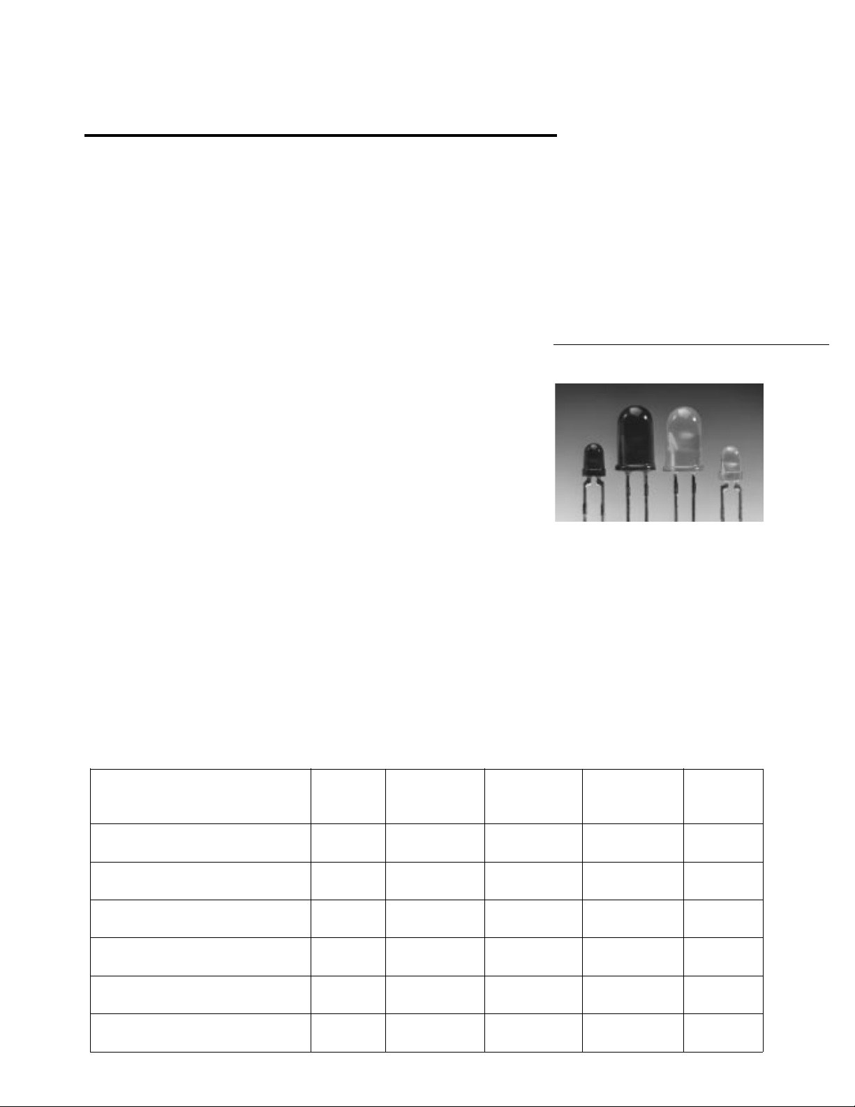
T-13/4 (5 mm), T-1 (3 mm), High
Performance, Tinted, Diffused,
AlInGaP, and TS AlGaAs Red
H
LED Lamps
Technical Data
Features
• High Light Output Over a
Wide Range of Currents
• Popular T-1 and T-13/4
Packages
• Choice of Three Colors
Amber
Reddish-Orange
Deep Red
• Wide Viewing Angles
• Long Life: Solid State
Technology
• Available on Tape and Reel
Applications
• Outdoor Message Boards
• Automotive Lighting
• Portable Equipment
• Medical Equipment
• Changeable Message Signs
Description
The HLMA-D/KXXX series tinted,
diffused, solid state lamps utilize
the newly developed aluminum
indium gallium phosphide
(AlInGaP) LED technology. This
technology has a very high
luminous efficiency, capable of
producing high light output over a
wide range of drive currents.
These LED lamps are available
with a choice of two colors, 592
HLMA-DX05 Series
HLMA-KX05 Series
HLMP-D1XX Series
HLMP-J100/J150 Series
nm amber and 615 nm reddishorange, and with two viewing
angles, 65° and 60°.
The HLMP-D/JXXX series tinted,
diffused solid state lamps utilize
the highly optimized transparent
substrate aluminum gallium
arsenide (TS AlGaAs) LED
technology. This technology has a
very high luminous efficiency,
Device Selection Guide
Viewing Reddish- Deep
Angle Amber Orange Red Package
Package Description 2θ1/2 λd = 592 nm λd = 615 nm λd = 644 nm Outline
T-13/4 (5 mm), Tinted, Diffused, 65° HLMA- HLMA- A
Standard Current DL05 DH05
T-1 (3 mm), Tinted, Diffused, 60° HLMA- HLMA- B
Standard Current KL05 KH05
T-13/4 (5 mm), Tinted, Diffused, 40° HLMP- A
Standard Current D115
T-13/4 (5 mm), Tinted, Diffused, 25° HLMP- A
Standard Current D120
T-1 (3 mm), Tinted, Diffused, 55° HLMP- C
Standard Current J100
T-1 (3 mm), Tinted, Diffused, 55° HLMP- C
Diffused, Low Current J150
5964-9287E
1-49
capable of producing high light
output over the wide range of
drive currents from 500 µA to
50 mA. The color is deep red at a
dominant wavelength of 644 nm.
TS AlGaAs is a flip-chip LED
technology, die attached to the
anode lead and wire bonded to
the cathode lead. Available viewing angles are 25°, 40°, and 55°.
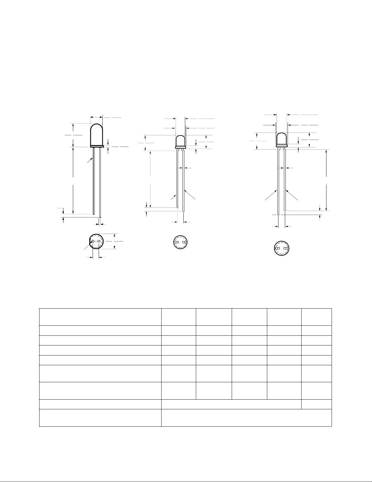
Package Dimensions
9.19 (0.362)
8.43 (0.332)
CATHODE
25.40
MIN.
(1.00)
1.27( 0.050) NOM.
CATHODE
NOTES:
1. ALL DIMENSIONS ARE IN MILLIMETERS (INCHES).
2. AN EPOXY MENISCUS MAY EXTEND ABOUT
1 mm (0.040") DOWN THE LEADS.
A
5.08 (0.200)
4.57 (0.180)
0.89 (0.035)
0.64 (0.025)
0.45 (0.018)
SQUARE
NOMIMAL
6.10 (0.240)
5.59 (0.220)
2.54 (0.100) NOM.
1.27
(0.050)
6.35 (0.250)
5.58 (0.220)
24.13
(0.95)
NOM.
MIN.
CATHODE
B
(0.040)
(0.018)
2.54
(0.100)
3.18 (0.125)
2.67 (0.105)
3.43 (0.135)
2.92 (0.115)
4.70 (0.185)
4.19 (0.165)
1.02
NOM.
0.45
SQUARE NOMINAL
ANODE
NOM.
6.35 (0.250)
5.58 (0.220)
ANODE
3.18 (0.125)
2.67 (0.105)
3.43 (0.135)
2.92 (0.115)
4.70 (0.185)
4.19 (0.165)
1.02
NOM.
(0.040)
0.45
(0.018)
SQUARE
NOMINAL
CATHODE
2.54
(0.100)
NOM.
24.13
(0.95)
1.27
(0.050)
MIN.
NOM.
C
HLMA-DL05/DH05/Kl05/KH05 AlInGaP Lamps
Absolute Maximum Ratings at T
Parameter DL05 DH05 KL05 KH05 Units
DC Forward Current
Peak Forward Current
Average Input Power
Reverse Voltage (IR = 100 µA) 55 55V
Operating Temperature Range -40 to -40 to -40 to -40 to °C
Storage Temperature Range -55 to -55 to -55 to -55 to °C
Junction Temperature 110 °C
Soldering Temperature 260° C for 5 second
[1.59 mm (0.06 in.) below seating plane]
Notes:
1. Derate linearly as shown in Figure 4.
2. Any pulsed operation cannot exceed the Absolute Max Peak Forward current as specified in Figure 5.
3. Drive currents between 10 mA and 30 mA are recommended for best long term performance.
4. Operation at currents below 10 mA is not recommended, please contact your Hewlett-Packard sales representative.
1-50
[1,3,4]
[2]
[2]
= 25°C
A
HLMA- HLMA- HLMA- HLMA-
50 50 50 50 mA
200 200 200 200 mA
103 103 103 103 mW
+100 +100 +100 +100
+100 +100 +100 +100
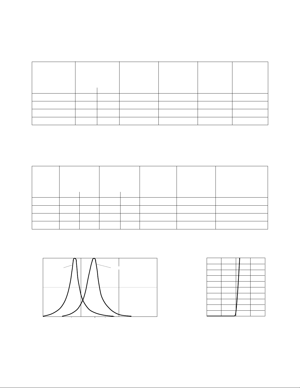
Optical Characteristics at T
= 25°C
A
Luminous Color, Viewing
Intensity Peak Dominant Angle Luminous
IV (mcd) Wavelength Wavelength 2 θ1/2 Efficacy
Part Number @ 20 mA
[1]
λ
(nm) λ
peak
[2]
(nm) Degrees
d
[3]
HLMA- Min. Typ. Typ. Typ. Typ. (lm/w)
DL05 35 100 594 592 65 480
DH05 35 100 621 615 65 263
KL05 35 100 594 592 60 480
KH05 35 100 621 615 60 263
Notes:
1. φv is the total luminous flux output as measured with an integrating sphere.
2. The dominant wavelength, λd, is derived from the CIE Chromaticity Diagram and represents the color of the device.
3. θ1/2 is the off-axis angle where the luminous intensity is 1/2 the peak intensity.
η
v
Electrical Characteristics at T
= 25°C
A
Forward Reverse Capacitance Speed of Response
Voltage Breakdown C (pF) τs (ns)
Part VF (Volts) VR (Volts) VF = 0, Thermal Time Constant
Number @ IF = 20 mA @ I
HLMA- Typ. Max. Min. Typ. Typ. Rθ
= 100 µA f = 1 mHz Resistance e
R
(°C/W) Typ.
J-PIN
DL05 1.9 2.4 5 25 60 260 13
DH05 1.9 2.4 5 25 60 260 13
KL05 1.9 2.4 5 25 60 290 13
KH05 1.9 2.4 5 25 60 290 13
1.0
AMBER
0.5
RELATIVE INTENSITY
0
550
600
594 621 630
WAVELENGTH – nm
REDDISH-ORANGE
700650
200
180
160
140
120
100
80
60
40
– FORWARD CURRENT – mA
F
20
I
0
1.5 2.0
1.0
VF – FORWARD VOLTAGE – V
-t/τs
2.5
3.0
Figure 1. Relative Intensity vs.
Wavelength.
Figure 2. Forward Current vs.
Forward Voltage.
1-51

2.5
2.0
1.5
1.0
(NORMALIZED AT 20 mA)
0.5
RELATIVE LUMINOUS INTENSITY
0.0
010 5020 4030
I
– DC FORWARD CURRENT – mA
F
50
45
40
Rθ = 618 °C/W
J-A
35
30
Rθ = 412 °C/W
J-A
25
20
15
F
10
I – FORWARD CURRENT – mA
5
0
05030
10 20 40 9060
T – AMBIENT TEMPERATURE – °C
A
70 80 100
50
40
30
20
10
AVG
I – AVERAGE CURRENT – mA
f ≥ 100 Hz
0
50 100
I – PEAK FORWARD CURRENT – mA
PEAK
f ≥ 1 KHz
f ≥ 300 Hz
150
200
Figure 3. Relative Luminous Intensity
vs. Forward Current.
1.0
0.9
0.8
0.7
0.6
0.5
0.4
0.3
NORMALIZED INTENSITY
0.2
0.1
0
100° 90°
80° 70° 60° 50° 40° 20° 10° 0°30° 10° 20° 30° 40° 50° 60° 70° 80° 90° 100°
ANGULAR DISPLACEMENT – DEGREES
Figure 4. Maximum Forward Current
vs. Ambient Temperature. Derating
Based on T
Max = 110°C.
J
Figure 6. Spatial Radiation Pattern for HLMA-DL05/DH05 65° Lamps.
Figure 5. Maximum Average Current
vs. Peak Forward Current.
1.0
0.9
0.8
0.7
0.6
0.5
0.4
0.3
NORMALIZED INTENSITY
0.2
0.1
0
100° 90°
80° 70° 60° 50° 40° 20° 10° 0°30° 10° 20° 30° 40° 50° 60° 70° 80° 90° 100°
ANGULAR DISPLACEMENT – DEGREES
Figure 7. Spatial Radiation Pattern for HLMA-KL05/KH05 60° Lamps.
1-52

HLMP-D115/D120/J100/J150 TS AlGaAs Red Lamps
Absolute Maximum Ratings at T
Parameter D115 D120 J100 J150 Units
DC Forward Current
Peak Forward Current
Average Input Power
Reverse Voltage (IR = 100 µA) 55 55V
Operating Temperature Range -55 to -55 to -55 to -55 to °C
Storage Temperature Range -55 to -55 to -55 to -55 to °C
Junction Temperature 110 °C
Soldering Temperature 260°C for 5 second
[1.59 mm (0.06 in.) below seating plane]
Notes:
1. Derate linearly as shown in Figure 12.
2. Any pulsed operation cannot exceed the Absolute Max Peak Forward current as specified in Figure 13.
[1]
[2]
[2]
= 25°C
A
HLMP- HLMP- HLMP- HLMP-
50 50 50 50 mA
300 300 300 300 mA
100 100 100 100 mW
+100 +100 +100 +100
+100 +100 +100 +100
Optical Characteristics at T
= 25°C
A
Luminous Color, Viewing
Intensity Peak Dominant Angle Luminous
IV (mcd) Wavelength Wavelength 2 θ
Part Number @ 20 mA
[1]
λ
(nm) λ
peak
[2]
(nm) Degrees
d
1/2
[3]
HLMP- Min. Typ. Typ. Typ. Typ. (lm/w)
D115 138 250 654 644 40 85
D120 138 350 654 644 25 85
J100 39 175 654 644 55 85
J150 1.3 3.0 654 644 55 85
Notes:
1. φv is the total luminous flux output as measured with an integrating sphere.
2. The dominant wavelength, λd, is derived from the CIE Chromaticity Diagram and represents the color of the device.
3. θ
is the off-axis angle where the luminous intensity is 1/2 the peak intensity.
1/2
Electrical Characteristics at T
= 25°C
A
Forward Reverse Capacitance Speed of Response
Voltage Breakdown C (pF) τs (ns)
Part VF (Volts) VR (Volts) VF = 0 Thermal Time Constant
Number @ IF = 20 mA @ I
HLMP- Min. Typ. Min. Typ. Typ. Rθ
= 100 µA f = 1 mHz Resistance e
R
(°C/W) Typ.
J-PIN
D115 1.85 2.4 5 20 20 260 45
D120 1.85 2.4 5 20 20 260 45
J100 1.85 2.4 5 20 20 290 45
J150 1.6 1.9 5 20 20 290 45
Efficacy
η
v
-t/τs
1-53

1.0
-1
10
300
200
100
2.4
2.0
1.0
50
0.5
-2
10
RELATIVE INTENSITY
-3
10
600 1000
WAVELENGTH – nm
700500
Figure 8. Relative Intensity vs.
Wavelength.
1.2
1.1
1.0
0.9
0.8
0.7
0.6
0.5
0.4
– RELATIVE EFFICIENCY
0.3
(NORMALIZED AT 20 mA)
V
η
0.2
0.1
0.0
5 300
21 200
I
PEAK
10 20 50 100
– PEAK FORWARD CURRENT – mA
20
10
5
– FORWARD CURRENT – mA
F
I
2
1
0.50
1.5 2.0 2.5 3.0
1.0 3.5
VF – FORWARD VOLTAGE – V
Figure 9. Forward Current vs.
Forward Voltage.
50
40
30
20
– FORWARD CURRENT – mA
10
F
I
RθJA = 400° C/W
RθJA = 550° C/W
0
0
40 80
20 60 100
TA – AMBIENT TEMPERATURE – °C
0.2
0.1
0.05
(NORMALIZED AT 20 mA)
RELATIVE LUMINOUS INTENSITY
0.01
10.5
IF – DC FORWARD CURRENT – mA
51020 50
2
Figure 10. Relative Luminous Intensity
vs. DC Forward Current.
50
40
f > 300 Hz
30
20
10
= AVERAGE FORWARD CURRENT – mA
AVG
0
I
f > 100 Hz
50
I
PEAK
150 250
100 200 300
– PEAK FORWARD CURRENT – mA
f > 1000 Hz
Figure 11. Relative Efficiency vs. Peak
Forward Current.
1-54
Figure 12. Maximum Forward Current
vs. Ambient Temperature. Derating
Based on T
Max = 110°C.
J
Figure 13. Maximum Average Current
vs. Peak Forward Current.

1.0
0.9
0.8
0.7
0.6
0.5
0.4
0.3
NORMALIZED INTENSITY
0.2
0.1
0
100° 90°
80° 70° 60° 50° 40° 20° 10° 0°30° 10° 20° 30° 40° 50° 60° 70° 80° 90° 100°
ANGULAR DISPLACEMENT – DEGREES
Figure 14. Spatial Radiation Pattern for 40° HLMP-D115 Lamp.
1.0
0.9
0.8
0.7
0.6
0.5
0.4
0.3
NORMALIZED INTENSITY
0.2
0.1
0
80° 70° 60° 50° 40° 20° 10° 0°30° 10° 20° 30° 40° 50° 60° 70° 80° 90° 100°
100° 90°
ANGULAR DISPLACEMENT – DEGREES
Figure 15. Spatial Radiation Pattern for 25° HLMP-D120 Lamp.
1.0
0.9
0.8
0.7
0.6
0.5
0.4
0.3
NORMALIZED INTENSITY
0.2
0.1
0
80° 70° 60° 50° 40° 20° 10° 0°30° 10° 20° 30° 40° 50° 60° 70° 80° 90° 100°
100° 90°
ANGULAR DISPLACEMENT – DEGREES
Figure 16. Spatial Radiation Pattern for 55° HLMP-J100-J150 Lamps.
1-55
 Loading...