

Page 1
Product Category: Monitors and Displays
Marketing Name / Model
[List multiple models if applicable.]
HP Elite S340c 34-in Curved Display
1.0 Items Requiring Selective Treatment
Quantity
in product
Printed Circuit Boards (PCB) or Printed Circuit
Assemblies (PCA)
With a surface greater than 10 sq cm
IF BD, POWER BD, F/K BD, Webcam BD
4
Batteries
All types including standard alkaline and lithium coin
or button style batteries
0
Mercury-containing components
For example, mercury in lamps, display backlights,
scanner lamps, switches, batteries
0
Liquid Crystal Displays (LCD) with a surface greater
than 100 sq cm
Includes background illuminated displays with gas
discharge lamps Panel
1
Cathode Ray Tubes (CRT)
0
Capacitors / condensers (Containing PCB /PCT)
Electrolytic Capacitors / Condensers measuring
greater than 2.5 cm in diameter or height
Power BD only (C805)
1
External electrical cables and cords
Type-C, HDMI, USB, DP cable, Power cord
5
Gas Discharge Lamps
0
Plastics containing Brominated Flame Retardants
0
Components and parts containing toner and ink,
including liquids, semi-liquids (gel/paste) and toner
Include the cartridges, print heads, tubes, vent
chambers, and service stations.
0
Components and waste containing asbestos
0
Components, parts and materials containing
refractory ceramic fibers
0
Components, parts and materials containing
radioactive substances
0
Product End-of-Life Disassembly Instructions
Purpose: The document is intended for use by end-of-life recyclers or treatmen t facilities. It provides the basic instructions
for the disassembly of HP products to remove components and materials requiring selective treatment, as defined by EU
directive 2002/96/EC, Waste Electrical and Electronic Equipment (WEEE).
1.1 Items listed below are classified as requiring selective treatment.
1.2 Enter the quantity of items contained within t he product which require selective treatment in the right column, as
applicable.
Item Description Notes
of items
included
EL-MF877-00 Page 1
Template Revision A
Page 2

2.0 Tools Required
List the type and size of the tools that would typically be used to disa ss em bl e the product to a point where components
Tool Description
Tool Size (if
applicable)
Description #1 SCREW DRIVER(PHILLIPS HEAD)
#1
Description #2 SCREW DRIVER(HEX HEAD)
#2
Description #3
Description #4
Description #5
3.0 Product Disassembly Process
and materials requiring selective treatment can be removed.
3.1 List the basic steps that should typically be f oll owed to remove components and materials requiring selective treatment:
1. Remove Stand/Base Assy From Display Head
2. Remove Rear Cover Assy From Display Head
3. Remove Bracket Assy frome Display
4. Remove Key Board and Speaker from Front Cover Assy
5. Disassemble Front Cover ASSY
6. Disassemble Webcam ASSY
7. Take 4pcs Al foil Off From Chassis Cover & Remove Panel
8. Take 10pcs Screw then remove Interface BD and Power BD
9. Press release Base Button than remove Stand Assy from Base Assy
10. Disassemble Stand Assy
11. Disassemble Base Assy
12. LCD Panel explode
3.2 Optional Graphic. If the disassembly process is complex, insert a graphic illustration below to identify the item s
contained in the product that require selective treatment (with descriptions and arrows identifying locations).
EL-MF877-00 Page 2
Template Revision A
Page 3

HP S340c Disassembly Process
ME-RD
Mechanical Engineer
Oct-12-2016
Page 4
Pick up display head
Pick up display head.
2
Page 5
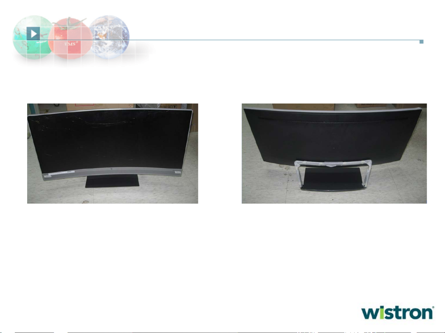
Display Head disassembly
Remove 4 screws
Disassembly RC
with tooling
Remove
web-cam
cable
3
Page 6

Display Head disassembly
Remove speaker cable
And 6 speaker screws
Remove LVDS
cable
Remove back light
cable And ear phone
cable
Remove tape
and key BD cable
Remove 4 BKT
screws
4
Page 7

Display Head disassembly
Remove Mid-cover
Screws (26 PCS) and 2
Front cover screws
Remove front cover
Remove
Mid-cover
5
Page 8

Disassembly Front cover Assy
Disassembly Lens
and gasket
Disassembly
long gasket and plastic
FC&AL part
6
Page 9

Disassembly Rear cover Assy
Remove web-cam
screws
Remove web-cam
Screws and cable
7
Page 10

Disassembly Mid-cover Assy
Disassembly Key frome
mid-cover
8
Page 11

Disassembly Bracket Assy
Remove PCB
Screws, gasket and cable
9
Page 12

Disassembly Stand and Base Assy
Remove 4 screws Disassembly
Remove Rubber and
PE bag
plastic part
Remove Rubber and
Depart plastic &Bracket
10
Page 13
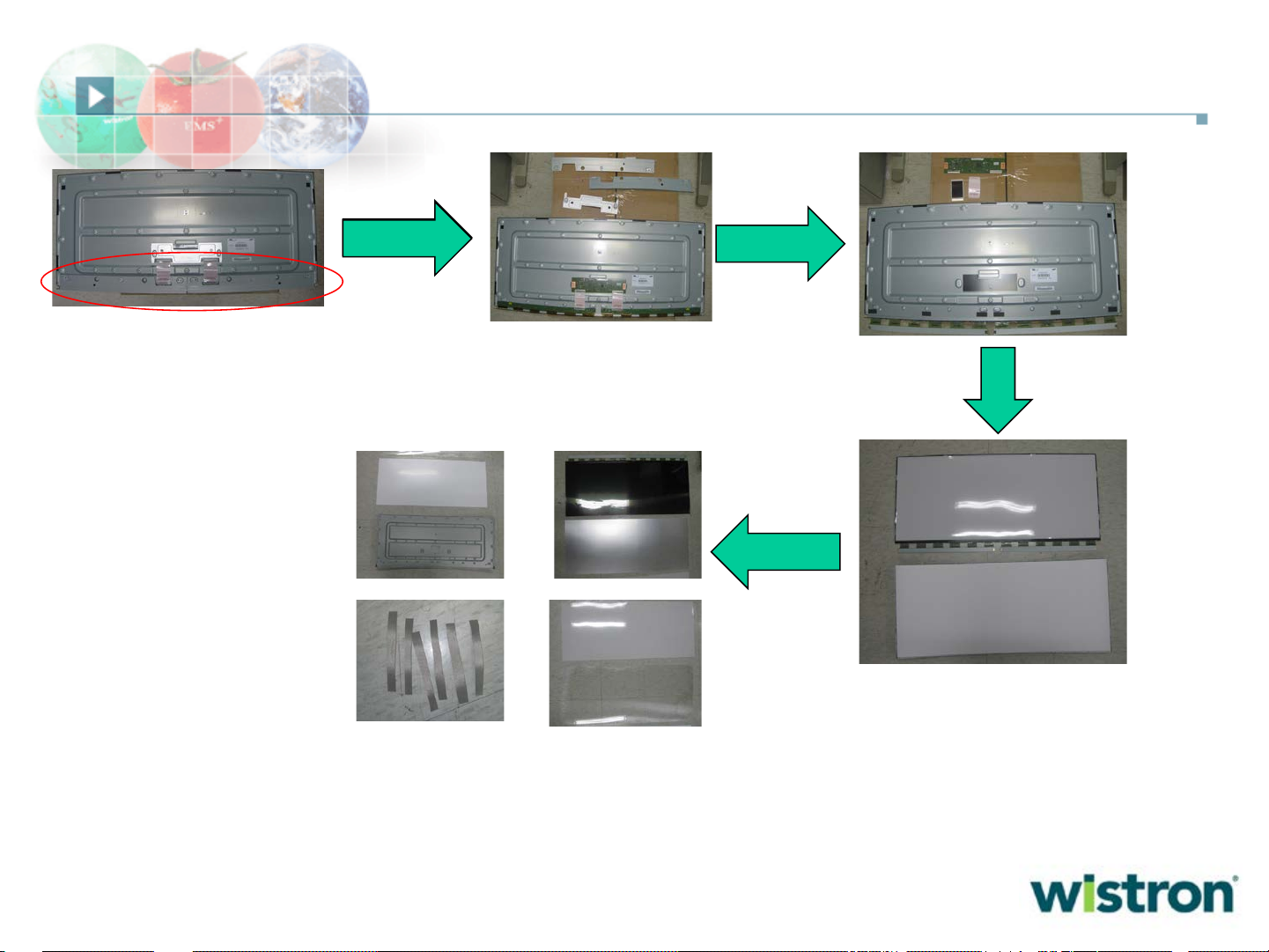
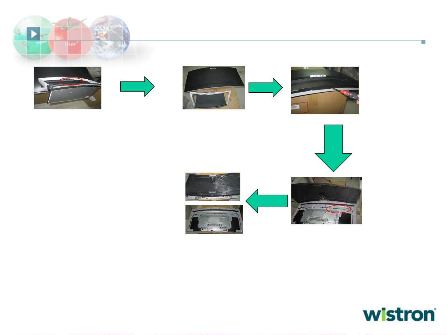
Disassembly Panel Assy
Remove T-con
Remove T-con
screws
screws
Remove PCB
Remove Mid-cover
And OC
11
Page 14

Thank You !!!
12
 Loading...