

Page 1
Compaq
Evo
D310
Micro Desktop
upgrade guide
www.hp.com/go/support
Page 2

Notice
The information contained in this document is subject to change without notice.
Hewlett-Packard makes no warranty of any kind with regard to this material, including, but not limited
to, the implied warranties of merchantability and fitness for a particular purpose. Hewlett-Packard shall
not be liable for errors contained herein or for incidental or consequential damages in connection with
the furnishing, performance, or use of this material.
This document contains proprietary information that is protected by copyright. All rights are reserved.
No part of this document may be photocopied, reproduced, or translated to another language without
the prior written consent of Hewlett-Packard Company.
Compaq™, the Compaq logo™, and Evo™ are trademarks of Compaq Information Technologies Group,
L.P. in the U.S. and other countries.
Adobe
Incorporated.
Microsoft
Corporation.
HP France
Business Desktop Division
38053 Grenoble Cedex 9
France
© 2002 Compaq Information Technologies, L.P.
© 2002 Hewlett-Packard Company
, Acrobat and Acrobat Reader™ are trademarks or registered trademarks of Adobe Systems
MS-DOS
,
Important Ergonomic Information
Improper and prolonged use of keyboards and input devices are among those tasks associated with repetitive strain injury (RSI) to soft
tissues in the hands and arms. If you do experience discomfort or pains while using any computing equipment, discontinue use
immediately and consult your physician as soon as possible.
Your comfort and safety are our primary concern. Consequently, we strongly recommend that you read HP’s ergonomic information
before using your PC. For detailed information, refer to HP’s online version of “Working in Comfort” which is preloaded on your HP
PC’s hard disk or visit HP’s Working in Comfort Web site at: www.hp.com/ergo/.
Windows and Windows NT are U.S registered trademarks of Microsoft
,
Page 3

Information Roadmap
Use the icon in Acrobat Reader to search for information in this PDF.
The following types of information are available for Business PCs:
Installing, Configuring, Upgrading
See the Upgrade Guide (this document) or the Service Handbook Chapter.
The Upgrade Guide will help you upgrade and replace components in your Business PC, including the
hard drive, memory, battery, power supply, and optical drives. More information is available on the HP
support web site (
The Service Handbook Chapter, available in PDF format on the support web site
(
www.hp.com/go/support
• Business PC configurations
•
Replacement parts
•
Available accessories.
Troubleshooting
See the Troubleshooting Guide.
www.hp.com/go/support
), provides information on:
).
The Troubleshooting Guide will help you solve problems with your Business PC. It is available in PDF
format on the HP support web site (
you:
• Find out what to do first if you encounter a problem with your computer
• Identify the problem area and provide a possible solution
• Find further service and support if you still can’t solve the problem
•
Collect relevant information on your computer before contacting support.
Technical Reference
See the Technical Reference Manual.
The Technical Reference Manual, available in PDF format on the support web site
(
www.hp.com/go/support
•
Your computer’s hardware components
•
The drivers, software and BIOS used in your computer.
www.hp.com/go/support
), provides information on:
). The Troubleshooting Guide will help
3
Page 4
Discover and use your product
See the Quick Start card and Quick User’s Guide.
The Quick Start card provided with your Business PC will help you:
•
Set up and begin using your Business PC for the first time
•
Upgrade and replace components in your Business PC, including the hard drive, processor memory,
add-on cards and optical drives. More information is available on the support web site
(
www.hp.com/go/support
• Find out where to get more information.
The Quick User’s Guide provided with your Business PC includes basic troubleshooting information,
technical specifications, warranty and legal information.
).
Your computer’s online information
Your computer may contain online help information on the hard disk, such as:
•
Troubleshooting and how to use HP Instant Support
• Linking to useful web sites.
If your computer is running Windows XP then you can access the Help and Support Center (HSC) via the
Start menu. HSC is an application which centralizes help topics, tutorials, troubleshooting etc.
Information on the hp support web site
Refer to the support web site (
• Downloadable documentation
• Service and support options
• The latest BIOS, drivers and utilities
• Answers to Frequently Asked Questions.
www.hp.com/go/support
System recovery cd-roms
Used for a full system recovery or alternative OS installation. Includes instructions on how to recover
your preloaded software including operating system, drivers and utilities.
) for a wide range of information, including:
4
Page 5

Finding Information
Use the following table to determine where to locate particular types of information:
Type of Information Location
•
Support phone numbers
•
Technical support contact information
•
Warranty information
•
How to set up your computer
•
Operation of your computer
•
Diagrams and detailed instructions on installing add-on devices
•
Internal wire connections for adding hard drives, CD-ROM, etc.
•
Memory expansion and replacing devices
•
LAN configuration
•
LAN controller
•
Identifying the problem
•
Information on errors
•
Problem solving
•
Troubleshooting
•
Parts list
•
Accessories list
•
BIOS
•
Connectors
•
IRQ
•
POST setup
•
Specifications
•
System board layout
•
Technical diagrams
•
Beep codes
Quick User’s Guide
Quick Start Card (details)
Quick User’s Guide (general information)
Operating system and application manuals
Upgrade Guide
Technical Reference Manual
Troubleshooting Guide
Service Handbook Chapter
Technical Reference Manual
5
Page 6

Important Safety Information
For your safety, never remove the PC’s cover without first removing the power cord and any connection to a
telecommunications network. Always replace the cover before switching the PC on again.
For your safety, always connect equipment to a grounded electrical wall outlet. Always use a power cord with a
properly grounded plug, such as the one provided with the equipment, or one in compliance with your national
safety standards. The equipment can be disconnected from the power by removing the power cord from the power
outlet. This means the equipment must be located close to an easily accessible electrical outlet.
To avoid electric shock, do not open the Power Supply Unit. There are no serviceable parts inside. For your safety,
only replace with a Power Supply Unit provided by HP Support Services. Ensure that the electrical power
requirements of your PC (refer to the label on the Power Supply Unit) can be suitably provided by your electrical
installation.
There is a danger of explosion if the battery is incorrectly installed. For your safety, never attempt to recharge,
disassemble or burn an old battery. Only replace the battery with the same or equivalent type, as recommended by
the manufacturer. The battery in this PC is a lithium battery that does not contain any heavy metals. Nevertheless, in
order to protect the environment, do not dispose of batteries in household waste. Please return used batteries either
to the shop from which you bought them, or to the dealer from whom you purchased your PC, or to HP, so that they
can either be recycled or disposed of in the correct way. Returned used batteries will be accepted free of charge.
Do not attempt to connect this product to the phone line during a lightning storm. Never install telephone jacks in
wet locations unless the telephone line has been disconnected at the network interface. Never touch uninsulated
telephone wires or terminals unless the telephone line has been disconnected at the network interface. Use caution
when installing or modifying telephone lines. Avoid using a telephone (other than a cordless type) during a lightning
storm. There may be a risk from lightning. Do not use the telephone to report a gas leak in the vicinity of the leak.
Never touch or remove the communications board without first removing the connection to the telephone network.
Use minimum Nº 26 AWG wire for telephone cable.
Warning: some parts inside the computer may be hot. Please wait for them to cool down before touching
them.
Choosing a Comfortable Workspace
Choose a workspace for your computer near a grounded electrical wall socket. If your monitor has a tiltswivel base, attach it to the monitor as described in the monitor manual. Position the monitor on your
desk. Position the computer to allow proper ventilation and access to the cables.
WARNING
If you are in doubt that you can lift the equipment safely, do not try to move it without help.
6
Page 7

Table of Contents
Upgrading and replacing hardware . . . . . . . . . . . . . . 9
Removing and replacing the pc’s cover . . . . . . . . . . . . . . 10
Inside the Evo D310 Micro Desktop . . . . . . . . . . . . . . . . 11
Upgrading or replacing memory . . . . . . . . . . . . . . . . . . . 12
System board cables and connectors . . . . . . . . . . . . . . . 13
Replacing the hard drive . . . . . . . . . . . . . . . . . . . . . . . . . 14
Installing optical drives . . . . . . . . . . . . . . . . . . . . . . . . . . 16
Configuring an IDE device after installation . . . . . . . . . . 17
Replacing the floppy disk drive . . . . . . . . . . . . . . . . . . . . 18
Installing or replacing an AGP or PCI accessory card . . . 20
Replacing the processor . . . . . . . . . . . . . . . . . . . . . . . . . 21
Replacing the system board . . . . . . . . . . . . . . . . . . . . . . 23
Replacing the power supply unit . . . . . . . . . . . . . . . . . . . 25
Replacing the battery . . . . . . . . . . . . . . . . . . . . . . . . . . . 26
7
Page 8

8
Page 9

Status
Upgrading and replacing hardware
This manual describes how to:
• Upgrade hardware components
• Replace faulty components.
If you want to find out about available accessories for your PC, refer to the following accessories Web
sites:
• www.hp.com/go/pcaccessories
• www.compaq.com/products/desktops/options/index.html.
Important - before you start
Read this section before installing any components in your PC.
Page 10

Upgrading and replacing hardware
WARNING
Caution Static electricity can damage electronic components. Turn all equipment OFF. Don’t let your clothes touch the accessory. To equalize
For your safety, never remove the PC’s cover without first removing the power cord from the power outlet, and any
connection to a telecommunications network. Always replace the cover before switching the PC on again.
the static electricity, rest the accessory bag on top of the PC while you are removing the accessory from the bag. Handle the accessory
as little as possible and with care.
Removing and replacing the pc’s cover
WARNING
For your safety, disconnect the power cord and all external cables.
1 Switch off the monitor and PC, disconnect all power cords and any telecommunication cables.
2 If necessary, unlock the cover (with the key) at the rear of the PC.
3 Open the latch and remove the cover.
4 Remove the front panel (if you are adding a front-access device or hard disk).
5 Replace the cover by following the previous instructions in reverse order.
10 Evo D310 Micro Desktop
Page 11

Inside the Evo D310 Micro Desktop
Hard Drive
You can replace hard drive with a larger
one (see page 14)
One Front-Access Device Shelf
CD-ROM drive, CD-RW drive, DVD drive or
Tape drive (see page 16)
Up to Three Accessory Boards
One AGP and Three PCI
Some slots may come with pre-installed
boards (see page 20)
Floppy Drive (below the hard drive)
(see
page 18))
Main Memory Modules:
(266MHz DDR SDRAM)
2 sockets for 128 MB, 256 MB, 512
MB or 1GB modules up to 2 GB
maximum (see page 12)
Upgrading and replacing hardware
Evo D310 Micro Desktop 11
Page 12
Upgrading and replacing hardware
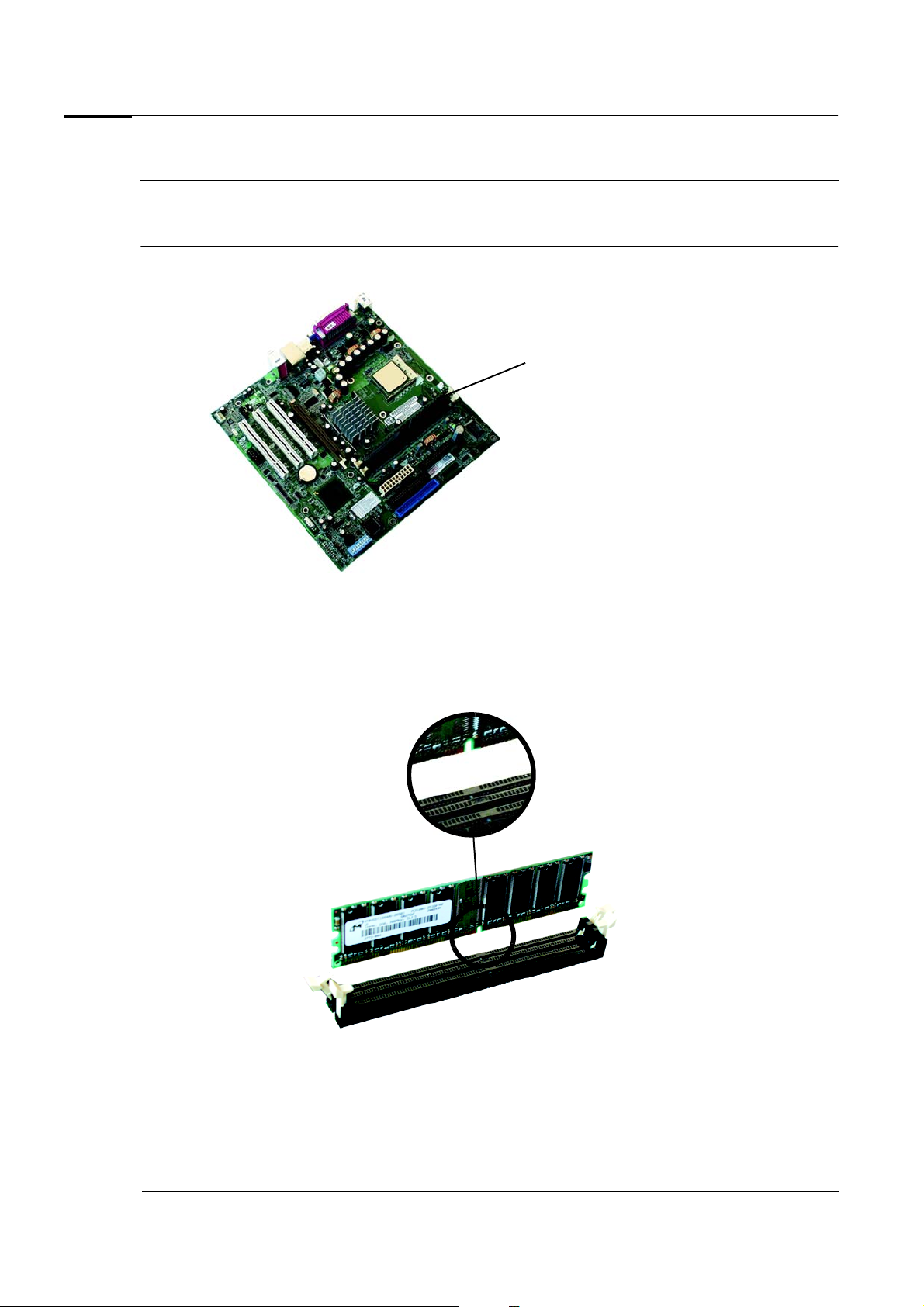
Upgrading or replacing memory
Note Use only memory modules provided for your PC model. The use of other memory modules is not supported. For information about
supported HP accessories, connect to
Install 128 MB, 256 MB or 512 MB non-ECC DDR SDRAM modules.
1 Switch off the PC and remove the computer’s cover. Refer to page 10.
www.hp.com/go/pcaccessories
. 32 MB and 64 MB modules are not supported.
position of memory
modules
2 Open the two tabs and remove the old memory module (if required).
3 There are two memory sockets. Start by fitting the socket nearest the processor. Modules of different
size (for example, 128MB or 256MB modules), can be fitted in any order.
4 Align the notches on the bottom of the module with the corresponding marks on the socket and push
it firmly into place. The clips close automatically.
5 Replace the cover. Refer to page 10.
12 Evo D310 Micro Desktop
Page 13
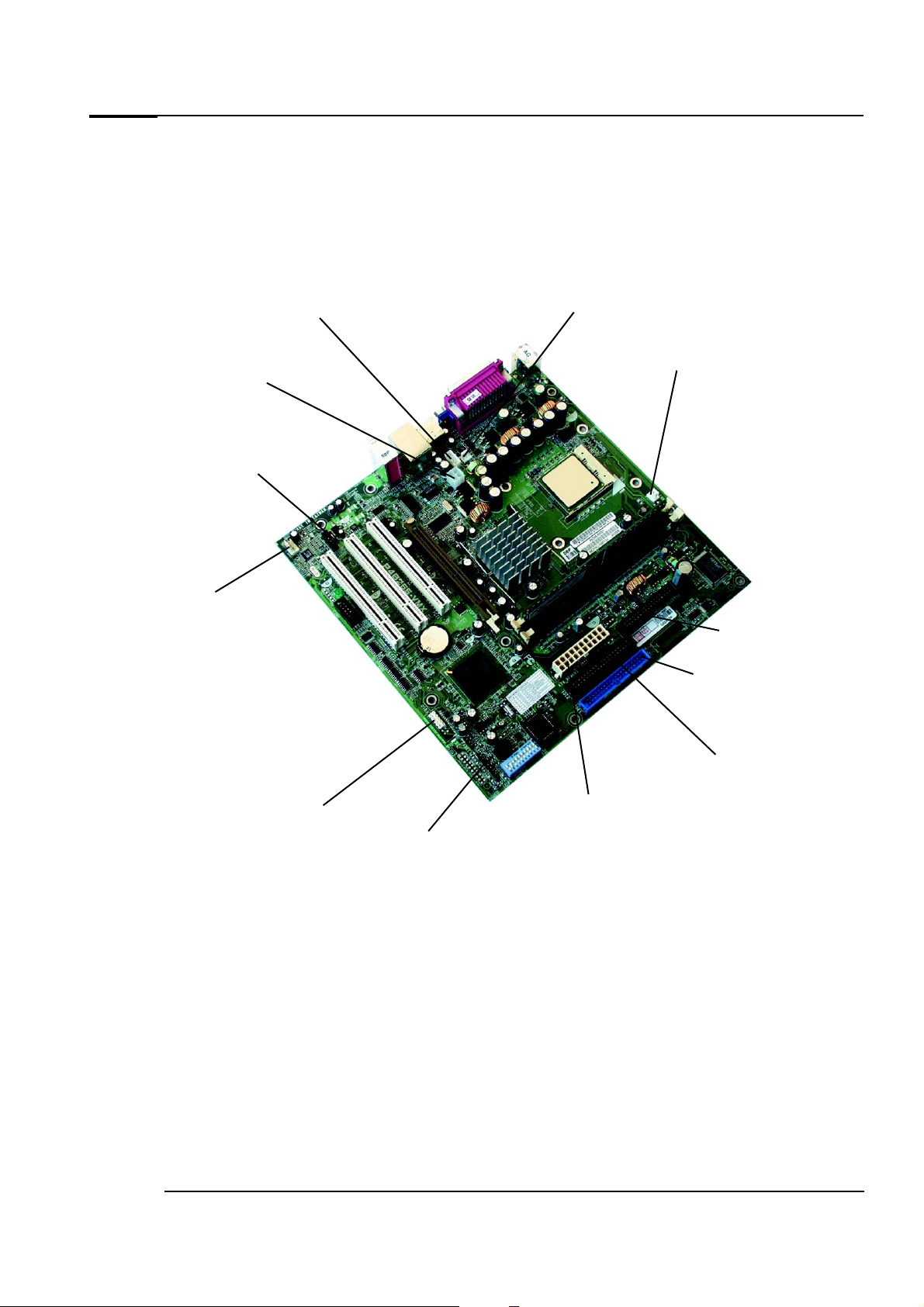
System board cables and connectors
Main Power
connector
Primary IDE connector
for Hard drive(s)
Floppy drive
Internal speaker (if
fitted)
Auxiliarly Power
connector (12V)
Chassis Intrusion
Chassis fan
Processor (CPU) fan
Status Panel
CD-ROM, DVD,
CD-RW or Tape
drive
Front USB Port
CD audio (if required)
Internal devices such as the power supply, processor, hard drives, DVD and CD-ROM drives require the
connection of data and power cables from device to system board. Cables are connected to the system
board and internal devices as shown below.
Upgrading and replacing hardware
Evo D310 Micro Desktop 13
Page 14

Upgrading and replacing hardware
Replacing the hard drive
WARNING
For your safety, disconnect the power cord and all external cables.
1 Switch off the PC and remove the PC’s cover and front panel. Refer to page 10.
2 Locate the hard drive and taking hold of the two large plastic latches that secure the bay, swing the
device bay upwards.
Right latch
Primary Hard drive
Left latch
3 Detach the data and power cables from the hard drive.
4 Standing at the rear of the PC, press the two tabs securing the hard drive inwards and carefully slide
the drive tray towards you and out of the PC.
Rear of the PC
14 Evo D310 Micro Desktop
Page 15
Upgrading and replacing hardware
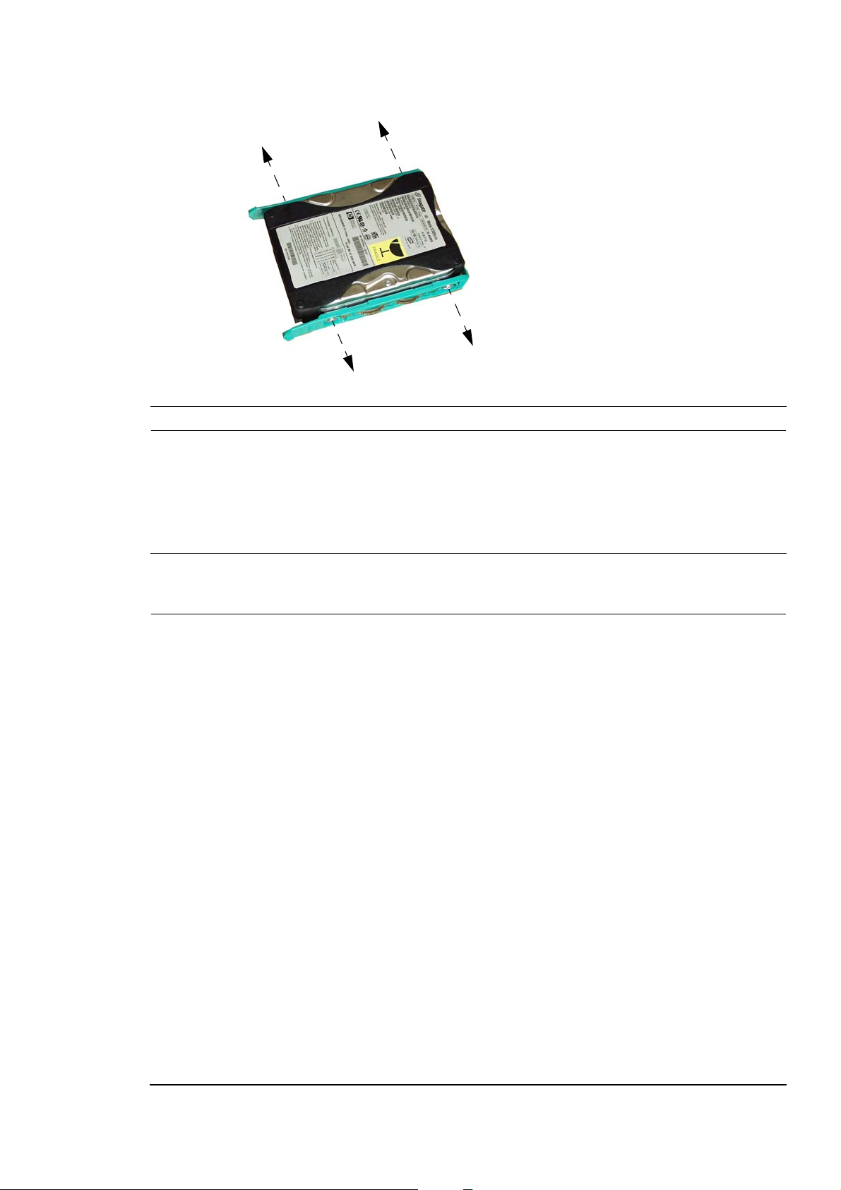
5 Remove the four screws securing the old drive to the tray.
6 Align the new drive in the tray (with the correct orientation), and tighten the screws.
Caution
Take care when handling the hard drive. A small drop can damage it.
7 Slide the drive tray back into the PC.
8 Attach the data and power connectors, rotate the drive bay back into place and close both latches.
9 Replace the PC’s front panel and cover. Refer to page 10.
10 Verify the new configuration by checking the Summary screen. To access the Summary Screen, press
immediately after startup, then press
F8
Esc
.
Note Ensure that you have installed all the required operating system and drivers on the newly installed drive. To reinstall operating system
and drivers, use the Recovery CD-ROMs provided with the PC. In addition, you can find the most up-to-date versions of drivers on the
support site at:
www.hp.com/go/support
.
Evo D310 Micro Desktop 15
Page 16

Upgrading and replacing hardware
Installing optical drives
WARNING
To avoid electrical shock and harm to your eyes by laser, do not open the laser module. The laser module should be serviced
by service personnel only. Do not attempt to make any adjustment to the laser unit. Refer to the label on the CD-ROM for
power requirements and wavelength. This product is a class 1 laser product.
You can install or replace optical drives, such as CD-ROM, CD-RW and DVD drives. To do this:
1 Switch off the PC and remove the PC’s cover and front panel. Refer to page 10.
2 Locate the optical drive and taking hold of the two large plastic latches that secure the bay, swing the
device bay upwards.
Right latch
optical drive
Left latch
3 Slide the old optical drive out the front of the PC.
4 Remove the clips from each side of the old drive by pulling on the protruding tabs.
5 Attach the clips to each side of the new drive by inserting first one pin then pressing on the middle of
the clip to allow the other pin to snap into place.
6 Slide the drive tray back into the PC until it clicks into place.
7 Attach the data and power connectors.
8 Replace the PC’s cover and front panel. Refer to page 10.
9 Verify the new configuration by checking the Summary screen. To access the Summary Screen, press
immediately after startup, then press
F8
Esc
.
16 Evo D310 Micro Desktop
Page 17

Configuring an IDE device after installation
After installing any device, you can check via the Summary Screen that your PC has correctly identified
the new configuration. To view the Summary screen, press
the list of options.
If the configuration is not correct, run the Setup program to configure the device. To enter the Setup
program, press
IDE drives are automatically detected by the Setup program. However, a newly installed device may
required that you install an appropriate device driver. Refer to your operating system documentation for
details. You can obtain the latest drivers from the support web site.
The IDE cables in your PC are cable select. You must, therefore, set the jumpers on any IDE devices you
install to cable select. See the documentation for the device for more information.
during startup, then select Setup from the list of options.
F8
Upgrading and replacing hardware
during startup, then select Summary from
F8
Evo D310 Micro Desktop 17
Page 18
Upgrading and replacing hardware
Replacing the floppy disk drive
1 Switch off the PC and remove the PC’s cover and front panel. Refer to page 10.
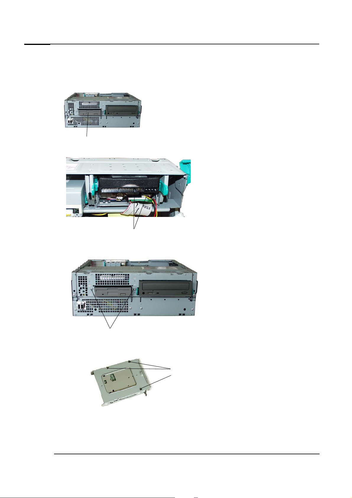
2 Locate the floppy drive.
floppy drive
3 Detach the data and power connectors from both the floppy and the hard drive (if installed).
data/power connectors
4 Remove the two screws securing the drive and slide it out of the front of the PC.
screws
5 Remove the three screws from the floppy drive tray.
screws
6 Align the new floppy drive in the tray and secure it using the three screws.
7 Replace the drive bay in the PC.
8 Attach the screws to the front of the tray.
18 Evo D310 Micro Desktop
Page 19

Upgrading and replacing hardware
9 Attach all data and power connectors and ensure the drive bay is rotated back into position.
10 Replace the PC’s cover and front panel. Refer to page 10.
11 Verify the new configuration by checking the Summary Screen. To access the Summary Screen, press
F8 during startup, then select the summary screen option.
Note Ensure that you have installed all the required operating system and drivers on the newly installed drive. To reinstall operating system
and drivers, use the Recovery CD-ROMs provided with the PC. In addition, you can find the most up-to-date versions of drivers on the
support Web site at:
www.hp.com/go/support
.
Evo D310 Micro Desktop 19
Page 20

Upgrading and replacing hardware
Installing or replacing an AGP or PCI accessory card
1 Switch off the PC and remove the PC’s cover. Refer to page 10.
2 Remove the retaining bracket.
3 Remove the slot cover and store it in a safe place in case you need it again or, if replacing a card,
remove the card.
4 If your are installing or replacing an AGP card, open the small latch located at the end of the slot.
5 Aligning the card carefully, slide it into position and press it firmly into the slot. If you are installing or
replacing an AGP card, close the latch located at the side of the slot.
6 Replace the retaining bracket.
7 Replace the cover. Refer to page 10.
20 Evo D310 Micro Desktop
Page 21

Replacing the processor
processor (covered by heatsink)
processor fan connector and
cable
screws
screws
1 Switch off the PC and remove the PC’s cover. Refer to page 10.
2 Locate the processor. It will be covered by a heatsink.
Upgrading and replacing hardware
3 Remove the screws from the heatsink and disconnect the processor fan cable..
4 Remove the heatsink. (If the processor is stuck to the heatsink, carefully detach the processor from
the heatsink, using a flat tool such as a screwdriver).
5 Lift the processor socket’s lever and carefully remove the old processor. Carefully insert the new
processor, then lower the lever back into place.
Evo D310 Micro Desktop 21
Page 22

Upgrading and replacing hardware
NOTE Insert the processor carefully. Ensure the orientation is correct - it can go in one way only.
6 Carefully remove all old thermal bonding material from the underside of the heatsink, by scraping it
off with a straight plastic edge (such as a plastic rule).
7 Remove the two paper protectors from the thermal interface material then affix it to the top of the
processor.
8 Attach the heatsink to the processor.
9 Secure the heatsink using the springs and screws.
1
3
10 Reconnect the processor fan cable to the system board.
Caution Ensure you use the correct system board connector (marked CPU FAN). If necessary, refer to “System board cables and connectors”
on page 13.
11 Replace the cover. Refer to page 10.
12 Ensure that the latest version of BIOS is installed on your PC. To learn which version of BIOS is
currently installed on your PC, press
To get the latest BIOS version for your PC, connect tothe support web site.
4
2
F8 during startup, then select Summary from the list of options.
22 Evo D310 Micro Desktop
Page 23
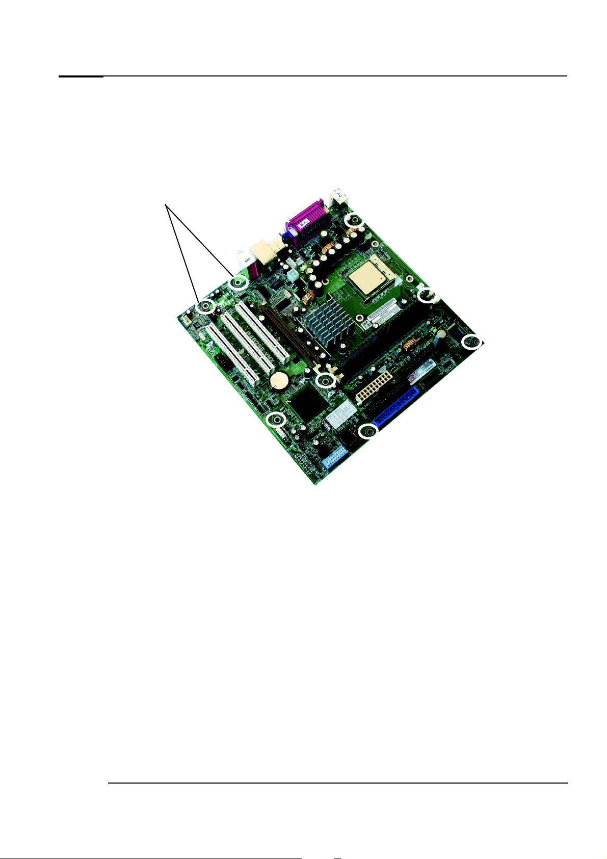
Replacing the system board
Screw positions
1 Switch off the PC and remove the PC’s cover. Refer to page 10.
2 Remove the main memory (page 12) and processor (page 21) from the old system board.
3 Remove all data, power and other cables from the old system board.
4 Remove the 8 screws securing the system board.
Upgrading and replacing hardware
5 Remove the old system board by carefully disengaging the rear connectors then carefully lifting it out
of the PC.
6 Insert the new system board, lining up the rear connectors carefully, and fasten the screws to secure
the board in place.
7 Replace the main memory (page 12) and processor, making sure you remember to use a new thermal
interface (page 21).
8 Reconnect all cables to the new system board (page 13).
9 Check the configuration switches are in the correct positions (as shown in the table on “Configuration
Switches” on page 24).
10 Replace the cover and front panel. Refer to page 10.
Evo D310 Micro Desktop 23
Page 24

Upgrading and replacing hardware
Configuration Switches
Switch Function Default
1-4 On Reserved Off
Off Reserved – Normal operation
5 On Clears CMOS and passwords
(to reload the Setup program defaults)
Off Normal operation
6 On Clears User and Administrator passwords Off
Off Normal operation
7 On BIOS recovery mode: forces booting in the BIOS boot block area Off
Off Normal operation
8 On Not used Off
Off Not Used - Normal operation
9 On Normal operation (Software boot block protection) On
Off Hardware boot block protection
10 On Not used Off
Off Not Used - Normal operation
Off
24 Evo D310 Micro Desktop
Page 25
Replacing the power supply unit
1 Switch off the PC and remove the computer’s cover. Refer to page 10.
2 Remove all internal power supply connectors. Note that there is both a main power and an auxiliary
power connector (see page 13).
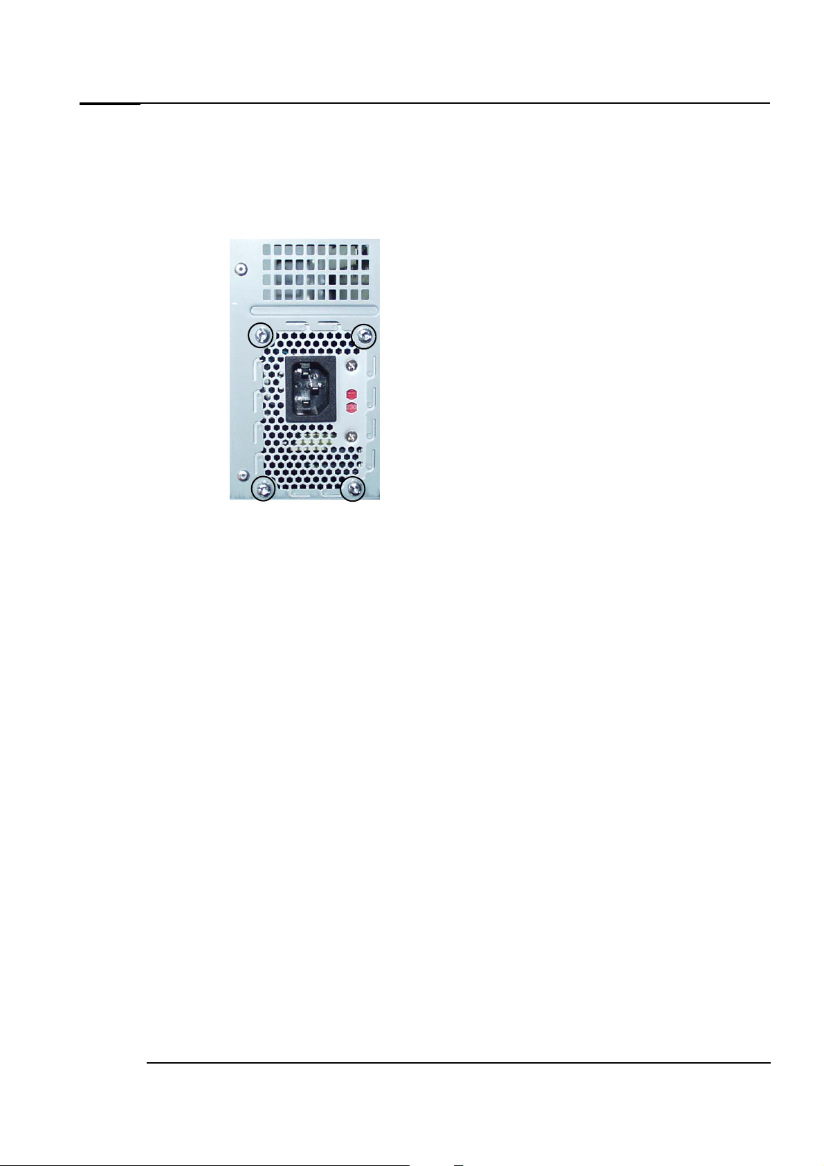
3 Remove the four external screws securing the power supply.
Upgrading and replacing hardware
4 Slide the old power supply away from the rear of the PC and lift it out.
5 Insert the new power supply, ensuring that it has engaged correctly underneath.
6 Replace the four screws to secure the power supply.
7 Reconnect all internal power supply connectors.
8 Replace the cover. Refer to page 10.
9 Select the correct voltage setting for your country.
Evo D310 Micro Desktop 25
Page 26

Upgrading and replacing hardware
Replacing the battery
WARNING
There is a danger of explosion if the battery is incorrectly installed. For your safety, never attempt to recharge,
disassemble or burn the old battery. Replace the battery only with the same or equivalent type recommended by the
manufacturer. The battery in this PC is a lithium battery which does not contain heavy metals, nevertheless, in order to
protect the environment, do not dispose of batteries in household waste. Please return used batteries to the shop from
which you bought them, or to the dealer from which you purchased y our PC, so tha t th ey can eit her be r ecycl ed o r di spo sed
of in an environmentally sound way. Returned used batteries will be accepted free of charge.
battery
1 Switch off the PC and remove the PC’s cover. Refer to page 10.
2 Remove the old battery by pressing the retaining clip with a flat-headed screwdriver and lifting the
battery clear.
3 Place the new battery in the battery holder, with the “+” sign on top and ensure that it is properly
seated.
4 Replace the PC’s cover. Refer to page 10.
26 Evo D310 Micro Desktop
Page 27

Page 28

Created in France, June 2002
 Loading...