

Page 1
Illustrated Parts & Service Map
HP Compaq 8000f Elite Business PC
Ultra Slim Desktop
© 2010 Hewlett-Packard Development Company, L.P. The information con-
tained herein is subject to change without notice. HP shall not be liable for
technical or editorial errors or omissions contained herein. Intel, Pentium,
Intel Inside, and the Intel logo are trademarks or registered trademarks of the
Intel Corporation and its subsidiaries in the U. S. and other countries.
Document Number 605649-002. 2nd Edition June 2010.
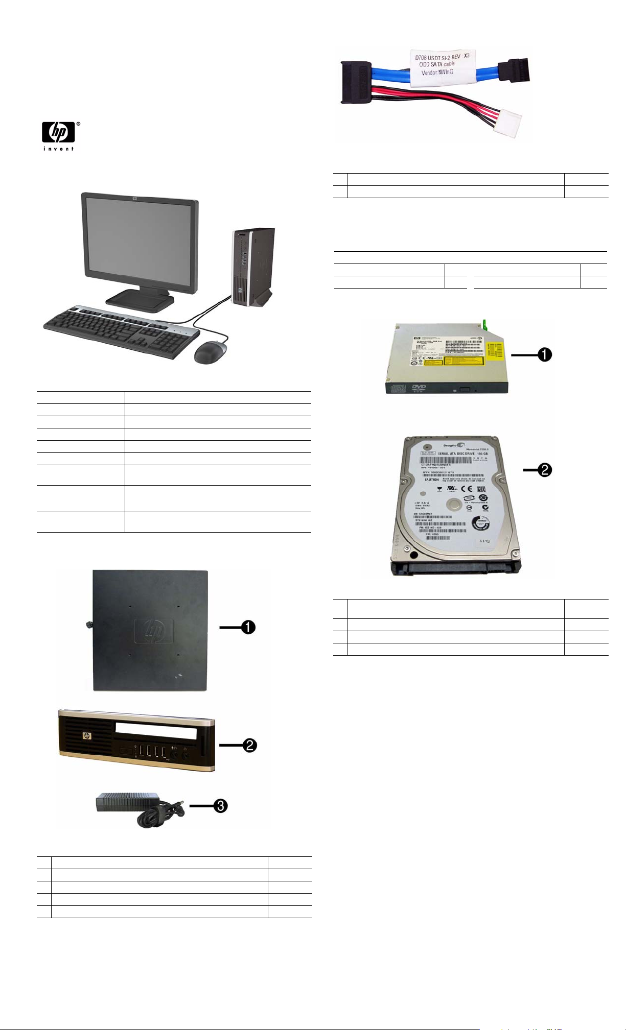
Cable and accessory
1 Optical drive cable/connector 605163-001
* Cable cover 588981-001
* Not shown
Keyboards (not illustrated)
USB, Basic 590271-xxx
Brazilian Portuguese -201 LA Spanish -161
French Canadian -121
U.S. -001
Key Specifications
Processor Type Intel® Core2 Duo
RAM Type DDR3-SDRAM DIMMs, PC3-10600 (1333 MHz) non-ECC
Maximum RAM Supported 4 GB
Expansion Slots (1) PCI Express Mini Card
Chipset Intel Q45 Express supporting Core 2 processors with vPro
Graphics Adapter Integrated Intel Graphics Media Accelerator 4500
Drive Support • Internal: (1) 2.5-inch
I/O Interfaces Front: (4) USB, microphone, headphone
Operating Systems • Windows 7 Professional 32
• External: (1) Slimline optical
Rear: (6) USB, PS/2 keyboard and mouse, line in, line out,
VGA, DisplayPort, RJ-45
• Windows 7 Home Premium 32
Spare Parts
Mass Storage Devices
1 DVD±RW and CD-RW Super Multi Double-Layer Combo Drive with
LightScribe. This kit also includes the drive bracket.
* 250 GB, 7200 RPM hard drive 608746-001
2 160 GB, 7200 RPM hard drive 608745-001
* 64 GB solid state drive (SSD) 581057-001
595115-001
System Unit
1 Access panel 587455-001
2 Front bezel 587457-001
3 AC adapter, 135W 587744-001
* Stand 593231-001
* Bezel blank, Jack Black 593230-001
* Not shown
HP Compaq 8000f Elite, USDT Chassis 605649-002 page 1
Page 2
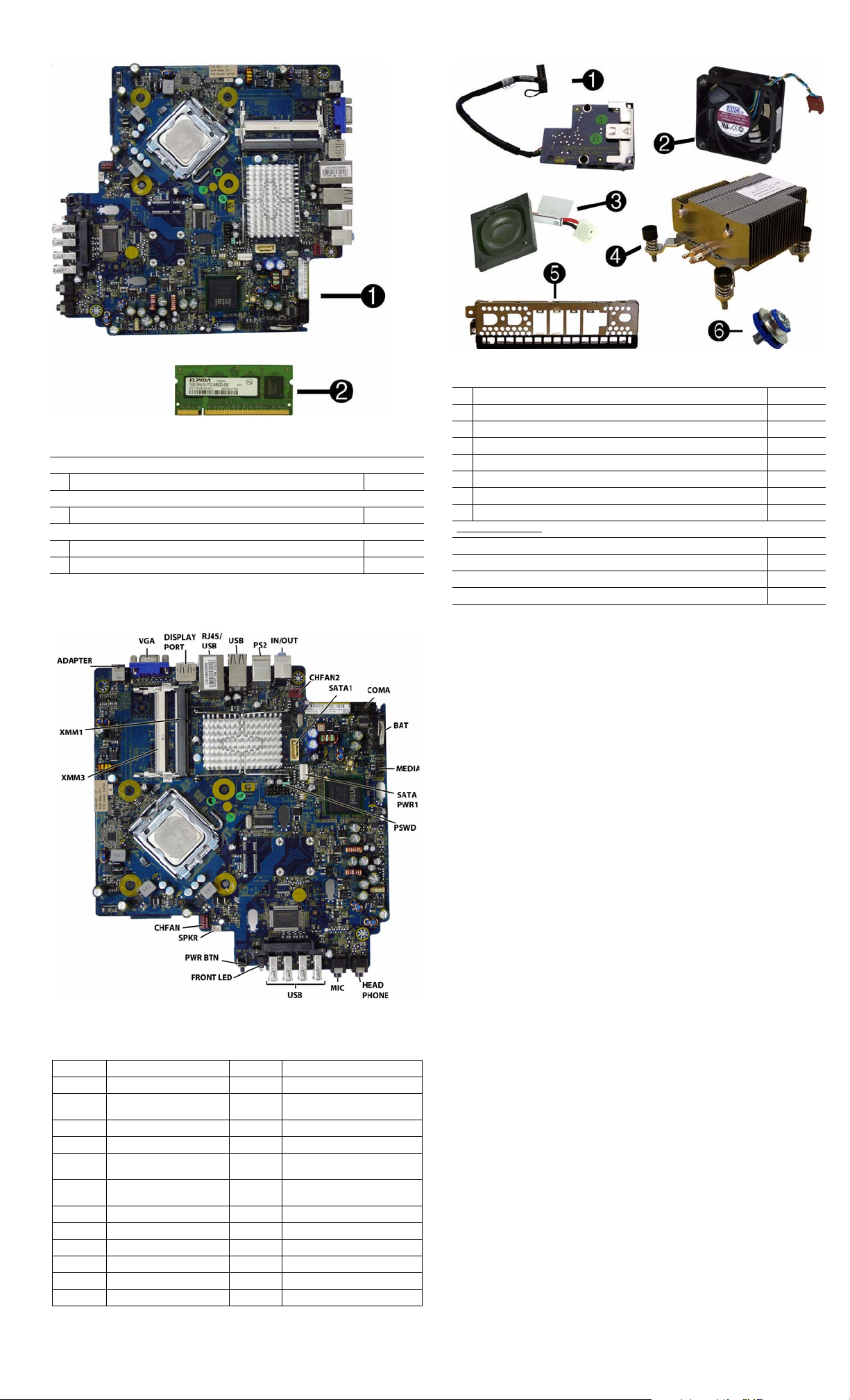
Standard and Optional Boards
System boards with thermal grease, alcohol pad, and CPU socket cover
1 System board 586717-001
Memory modules (PC3-10600, CL9)
22 GB
Intel Core 2 Duo Processors with alcohol pad and thermal grease
* E8400, 3.00 GHz, 6-MB L2 cache 509554-001
* E7600, 3.06 GHz, 3-MB L2 cache 573954-001
* Not shown
605157-001
System Board
Miscellaneous Parts
1 Card reader assembly 593235-001
2 Chassis fan, rear 605155-001
3 Internal speaker 605156-001
4 Heatsink with alcohol pad and factory-applied thermal grease 587456-001
5 Front I/O panel 587458-001
6 Grommet, hard drive 594220-001
* Chassis fan, front 605154-001
* Mouse, USB 605162-001
Power cord for use in:
Argentina 605160-001
Brazil 605159-001
Italy 605161-001
United States 605158-001
*Not shown
System Board Connectors and Jumpers (position of some untitled
components may vary in location)
ADAPTER DC power input PSWD Password header/jumper (E49)
VGA Video connector CMOS Clear CMOS
DISPLAYPORT
RJ45/USB Stacked RJ-45/Dual USB MIC Microphone jack
USB Quad stacked USB USB USB ports (4)
PS2
IN/OUT Double stacked line-out/line-inPWR BTN System front power button
CHFAN2 Chassis fan SPKR Internal speaker
SATA1 Second SATA connector CHFAN Front fan connector
COMA Primary serial port XMM3 SODIMM 3
BAT Real-time-clock battery XMM1 SODIMM 1
MEDIA
SATAPWR1
Display port connector HEAD-
Stacked keyboard/mouse
connector
Media reader
SATA power header
PHONE
FRONT
LED
ADAPTER DC power input
Headphone jack
System power LED
HP Compaq 8000f Elite, USDT Chassis 605649-002 page 2
Page 3

System Setup and Boot
Basic system information regarding system information, setup, power management, hardware,
and passwords is maintained in the Setup Utility held in the system ROM. The Setup Utility is
accessed by pressing the F10 key when prompted (on screen) to do so during the boot sequence.
If the screen prompt opportunity is missed, a restart will be necessary. For more information
about Setup Utilities refer to the Service Reference Guide.
Computer Setup Menu
Heading Option/Description
File System Information - Lists the following main system specifications:
• Product name
• SKU number (some models)
• Processor type/speed/stepping
• Cache size (L1/L2)
• Installed memory size/speed/
channels
• Integrated MAC Address
About - Displays copyright notice.
Set Time and Date - Allows you to set system time and date.
Flash System ROM - Allows you to select a drive containing a new BIOS.
Replicated Setup - Save to Rmv Media and Restore from Rmv Media
Default Setup
• Save Current Settings as Default
• Restore Factory Settings as Default
Apply Defaults and Exit - Applies the selected default settings and clears
any established passwords.
Ignore Changes and Exit - Exits Computer setup without saving changes.
Save Changes and Exit - Saves changes to system configuration or default
settings and exits Computer Setup.
Storage Device Configuration - Lists all installed BIOS-controlled storage devices.
Security Setup Password - Allows you to set and enable the setup (Administrator)
Power OS Power Management - Allows you to enable/disable Runtime Power
The following options are available:
•CD-ROM
•Hard Disk
• Translation Mode
• Default Values
• SATA Defaults
• Removable Media Boot
•eSATA Port
• Max eSATA Speed
• SATA Emulation
DPS Self-Test - Allows you to execute self-tests on ATA hard drives.
Boot Order - Allows you to specify boot order.
• Shortcut to Temporarily Override Boot Order
password.
Power-On Password - Allows you to set and enable power-on password.
Password Options - When any password exists allows you to lock legacy
resources, enable/disable network server mode, specify password requirement for warm boot, and allows you to enable/disable Setup Browse Mode.
Smart Cover (some models) - Allows you to lock/unlock cover lock and set
status of cover removal sensor.
Device Security (some models) - Enables/disables all I/O ports, audio, network controllers, SMBus controller, SATA ports, eSATA, and embedded
security devices.
USB Security - Allows you to set Device Available/Device Hidden for front
USB ports 3-6, rear USB ports 7-12, internal USB ports 1-2.
Slot Security - Allows you to disable any PCI or PCI Express slot.
Network Service Boot - Enables/disables boot from OS on a server.
System IDs - Allows you to set Asset tag, Ownership tag, Chassis serial
number, UUID, and keyboard locale setting.
DriveLock Security - Allows you to assign/modify a hard drive password for
added security.
System Security (some models) - Allows you to enable/disable:
• Data Execution Prevention
• PAVP (Protect Audio Video Path) (some models)
• Virtualization Technology
• Virtualization Technology Directed I/O
• Trusted Execution Technology
• Embedded Security Device Support
• OS management of Embedded Security Device through OS
Master Boot Record Security - Protects the master boot record from viruses
or other corruption. Saves of copy of the current master boot record.
Setup Security Level - Provides method to allow users limited access to
change specified setup options without knowing Setup password.
Management, Idle Power Savings, ACPI S3 Hard Disk Reset, ACPI S3 PS2
Mouse Wakeup, USB Wake on Device Insertion (some models), Unique
Sleep State Blink Rates.
Hardware Power Management - Allows you to enable/disable SATA bus
power management and S5 maximum power savings.
Thermal - Allows you to control minimum permitted fan idle speed.
• System BIOS
• Chassis serial number
• Asset tracking number
• ME firmware version
• Management node
Computer Setup Menu (Continued)
Heading Option / Description
Advanced Power-On Options - Allows you to set:
• POST mode - QuickBoot, FullBoot, Clear Memory, FullBoot every x
days
• POST messages - Enable/disable
• F9 prompt - Enable/disable
• F10 prompt - Enable/disable
• F12 prompt - Enable/disable
• Factory Recovery Boot Support - Enable/disable
• Option ROM prompt - Enable/disable
• Remote wakeup boot source - Remote server/local hard drive
• After Power Loss - Off/on/previous state
• POST delay - None, 5, 10, 15, or 20 seconds
• Bypass F1 Prompt on Configuration Changes - Enable/disable
Execute Memory Test (some models) -Restarts computer and executes
POST memory test.
BIOS Power-On - Allows you to set the computer to turn on at a preset time.
Onboard Devices - Allows you to set resources or disable onboard system
devices.
PCI Devices - Lists installed PCI devices with their IRQ settings and allows
you to reconfigure IRQ or disable devices.
PCI VGA Configuration - Allows you to specify which VGA controller will
be used when multiple video adapters are available.
Bus Options (some models) - Allows you to enable/disable PCI SERR#
Generation and PCI VGA palette snooping.
Device Options - Allows you to set:
• Printer Mode - Bi-Directional, EPP & ECP, Output Only
• Num Lock state at power-on - off/on
• S5 Wake on LAN - enable/disable
• Multi-Processor - enable/disable
• Internal speaker - enable/disable
• Monitor Tracking - enable/disable
• NIC PXE Option ROM Download - enable/disable
Management Devices - Only displayed in Advanced menu when BIOS
detects multiple management options.
Management Operations - Allows you to set:
• MEBx Setup Prompt - enable/disable
• Intel Remote PC Assist Prompt - enable/disable
• Intel PC Assist Timeout - 5, 10, 15, 20, 30, 40, 50, 60, 120, 180, 240 seconds
• SOL Terminal Emulation Mode - enable/disable
• SOL Keyboard - enable/disable
• Unprovision AMT on next boot
HP Compaq 8000f Elite, USDT Chassis 605649-002 page 3
Page 4

Password Security
This computer supports two security password features that are established through the
Computer Setup Utilities menu: setup password and power-on password. When you establish
only a setup password, any user can access all the information on the computer except Computer
Setup. When you establish only a power-on password, the power-on password is required to
access Computer Setup and any other information on the computer. When you establish both
passwords, only the setup password will give you access to Computer Setup.
When both passwords are set, the setup password can also be used in place of the power-on
password as an override to log in to the computer.
If you forget the password for the computer, you can clear that password so you can gain access
to the information on the computer by resetting the password jumper.
Clearing and Resetting CMOS
The computer’s configuration memory (CMOS) stores information about the computer’s configuration. The CMOS button resets CMOS but does not clear the power-on and setup passwords. Clearing CMOS will clear the Active Management Technology (AMT) settings in the
Management Engine BIOS Extension (MEBx), including the password. The password will
default to “admin” and will need to be reset. The AMT settings will also need to be reset. To
access the MEBx, press Ctrl+P during POST.
1. Turn off the computer and any external devices, and disconnect the power cord.
2. Disconnect the keyboard, monitor, and any other external equipment.
3. Remove the access panel.
4. Locate, press, and hold the CMOS button in for five seconds.
5. Replace the access panel.
6. Reconnect the external devices.
7. Plug in the computer and turn on power.
Clearing or Disabling a Power-On or Setup password
1. Shut down the operating system properly, then turn off the computer and any external devices,
and disconnect the power cord.
2. With the power cord disconnected, press the power button again to drain any residual power.
3. Remove the access panel.
4. Locate the header and jumper. The password jumper is green.
5. Remove the jumper from pins 1 and 2. Place the jumper on either pin 1 or 2, but not both.
6. Replace the access panel.
7. Reconnect the external equipment.
8. Plug in the computer and turn on power. Allow the operating system to start. This clears the
current passwords and disables the password features.
9. To establish new passwords, repeat steps 1 through 4, replace the password jumper on pins 1
and 2, then repeat steps 6 through 8. Establish the new passwords in Computer Setup.
Hewlett-Packard Vision Diagnostics
The Hewlett-Packard Vision Diagnostics utility allows you to view information about the hardware configuration of the computer and perform hardware diagnostic tests on the subsystems of
the computer. The utility simplifies the process of effectively identifying, diagnosing, and isolating hardware issues.
Use HP Vision Diagnostics to determine if all the devices installed on the computer are recognized by the system and functioning properly. Running tests is optional but recommended after
installing or connecting a new device.
To access HP Vision Diagnostics, you must create a Recovery Disc Set then boot to the CD containing the utility. It can also be downloaded from http://www.hp.com and either burned to CD
or installed to a USB flash drive.
1. In Windows Explorer, go to C:\SWSetup\ISOs and burn the file Vision Diagnostics.ISO to a
CD or copy it to a USB flash drive.
2. While the computer is on, insert the CD in the optical drive or USB flash drive in a USB port.
3. Shut down the operating system and turn off the computer.
4. Turn on the computer. The system will boot into HP Vision Diagnostics.
NOTE: If the system does not boot to the CD in the optical drive or to the USB flash drive,
you may need to change the boot order in the Computer Setup (F10) utility.
5. At the boot menu, select either the HP Vision Diagnostics utility to test the various hardware
components in the computer or the HP Memory Test utility to test memory only.
NOTE: The HP Memory Test is a comprehensive memory diagnostic utility that is run as a
stand-alone application, outside of HP Vision Diagnostics.
6. If running HP Vision Diagnostics, select the appropriate language and click Continue.
7. In the End User License Agreement page, select Agree if you agree with the terms. The HP
Vision Diagnostics utility launches with the Survey tab displayed.
Diagnostic LEDs
Activity
Green pwr
LED On
Green LED,
1 blink/2
seconds
Red LED, 1
blink/sec, 2
sec pause
Red LED,
3 blinks/sec,
2 sec pause
Red LED,
4 blinks/sec,
2 sec pause
Beeps
Possible Cause Recommended Action
None Computer on. None.
None Computer in Suspend to
RAM mode (some models
only) or normal Suspend
mode.
2 Processor thermal pro-
tection activated: A fan
may be blocked or not
turning.
OR
The heat sink/fan
assembly is not properly
attached to the processor.
3 Processor not installed
(not an indicator of bad
processor).
4 Power failure (power
supply is overloaded).
None required. Press any key or move the
mouse to wake the computer.
1. Ensure computer air vents not blocked
and processor cooling fan running.
2. Open hood, press power button, see if processor fan spins. If not spinning, make sure
fan's cable plugged onto system board
header.
3. If fan plugged in, but not spinning,
replace heat sink/fan assembly.
1. Check if processor is present.
2. Reseat processor.
1. Open hood and ensure the 4 or 6-wire
power supply cable is seated into connector
on system board.
2. Check if a device is causing the problem
by removing ALL attached devices. Power
on system. If system enters the POST, then
power off and replace one device at a time
and repeat until failure occurs. Replace
device causing failure. Continue adding
devices one at a time to ensure all devices
functioning properly.
3. Replace the power supply.
4. Replace the system board.
Red LED,
5 blinks/sec,
2 sec pause
Red LED,
6 blinks/sec,
2 sec pause
Red LED,
7 blinks/sec,
2 sec pause
Red LED,
8 blinks/sec,
2 sec pause
Red LED,
9 blinks/sec,
2 sec pause
Red LED,
10 blinks/
sec, 2 sec
pause
Red LED,
11 blinks/
sec, 2 sec
pause
System does
not power
on and
LEDs are
not flashing
Common POST Error Messages
Screen Message Probable Cause Recommended Action
101-Option ROM
Error
103-System Board
Failure
164-Memory Size
Error
214-DIMM Configuration Warning
301-, 304-Keyboard error
501-Display
Adapter Failure
1720-SMART Hard
Drive Detects
Imminent Failure
1796-SATA
Cabling Error
1801-Microcode
Patch Error
5 Pre-video memory
error.
6 Pre-video graphics
error.
7 System board failure
(ROM detected failure
prior to video).
8 Invalid ROM based on
bad checksum.
9 System powers on but is
unable to boot.
10 Bad option card. 1. Check each option card by removing the
11 The current processor
does not support a feature previously enabled
on this system.
None System unable to power
on.
1. System ROM checksum
error.
2. Expansion board option
ROM checksum
DMA, timers 1. Clear CMOS memory.
Incorrect memory configuration
Populated DIMM configuration is not optimized
Keyboard failure. Check keyboard connection or keys.
Graphics display controller. 1. Reseat graphics card.
Hard drive is about to fail. 1. Determine if hard drive is giving
One or more SATA devices
are improperly attached. For
optimal performance, the
SATA 0 and SATA 1 connectors must be used before
SATA 2 and SATA 3.
Processor not supported by
ROM B IOS.
1. Reseat DIMMs.
2. Make sure a DIMM is installed in black
DIMM connector first if only one DIMM.
3. Replace 3rd-party with HP memory.
4. Replace system board.
For systems with a graphics card:
1. Reseat graphics card.
2. Replace graphics card.
3. Replace system board.
For systems with integrated graphics,
replace system board.
Replace system board.
1. Reflash system ROM with latest BIOS
image.
2. Replace system board.
1. Check that voltage selector, located on the
rear of power supply (some models), is set to
appropriate voltage. Proper voltage setting
depends on region.
2. Unplug power cord from computer, wait
30 seconds, plug back in.
3. Replace system board.
4. Replace processor.
card (one at a time if multiple cards), then
power on system to see if fault goes away.
2. Once bad card identified, remove and
replace bad option card.
3. Replace system board.
1. Install a TXT capable processor.
2. Disable TXT in Computer Setup (F10)
utility.
3. Reinstall original processor.
Press and hold power button for less than 4
seconds. If hard drive LED turns green,
power button working correctly. Try the following:
1. Check that voltage selector (some models), located on the rear of power supply, is
set to appropriate voltage. Proper voltage
setting depends on region.
2. Replace system board.
OR
Press and hold power button for less than 4
seconds. If hard drive LED does not turn on
green then:
1. Check that unit plugged into a working
AC outlet.
2. Open hood and check that power button
harness is properly connected to system
board.
3. Check that both power supply cables are
properly connected to system board.
4. Check if 5V_aux light on system board is
turned on. If yes, replace power button harness. If problem persists, replace system
board.
5. If 5V_aux light on system board is not
turned on, remove expansion cards one at a
time until 5V_aux light on system board
turns on. It problem persists, replace power
supply.
1. Verify ROM, reflash if required
2. Remove suspected card, reboot
3. Clear CMOS memory
4. If message disappears, may be
problem with expansion card
5. Replace system board
2. Remove expansion boards.
3. Replace system board.
1. Run Setup (F10).
2. Check DIMMs for proper seating,
type, and HP compatibility.
3. Remove DIMMs singularly and
reboot to isolate faulty DIMM.
4. Replace system board.
Rearrange DIMMs so that each channel
has the same amount of memory.
Check connector for bent of missing
pins. Replace keyboard. If 304, possible
system board problem.
2. Clear CMOS.
3. Check monitor connection.
4. Replace graphics card.
correct error message. Enter
Computer Setup and run the Drive
Protection System test under Storage
> DPS Self-test.
2. Apply hard drive firmware patch if
applicable.
3. Back up contents and replace hard
drive.
Ensure SATA connectors are used in
ascending order. For one device, use
SATA 0. For two devices, use SATA 0
and SATA 1. For three devices, use
SATA 0, SATA1, and SATA 2.
1. Upgrade BIOS to proper version.
2. Change the processor.
HP Compaq 8000f Elite, USDT Chassis 605649-002 page 4
 Loading...