

Page 1

HP ENVY 4 Sleekbook
HP ENVY 4 Ultrabook
HP ENVY TouchSmart 4 Sleekbook
HP ENVY TouchSmart 4 Ultrabook
Maintenance and Service Guide
IMPORTANT! This document is intended for HP
authorized service providers only.
Page 2

© Copyright 2012 Hewlett-Packard
Development Company, L.P.
Bluetooth is a trademark owned by its
proprietor and used by Hewlett-Packard
Company under license. Intel is a
trademark of Intel Corporation in the U.S.
and other countries. Microsoft and Windows
are U.S. registered trademarks of Microsoft
Corporation. SD Logo is a trademark of
its proprietor.
The information contained herein is subject
to change without notice. The only
warranties for HP products and services are
set forth in the express warranty statements
accompanying such products and services.
Nothing herein should be construed as
constituting an additional warranty. HP shall
not be liable for technical or editorial errors
or omissions contained herein.
First Edition: December 2012
Document Part Number: 683019-001
Page 3

Safety warning notice
WARNING! To reduce the possibility of heat-related injuries or of overheating the device, do not
place the device directly on your lap or obstruct the device air vents. Use the device only on a hard,
flat surface. Do not allow another hard surface, such as an adjoining optional printer, or a soft
surface, such as pillows or rugs or clothing, to block airflow. Also, do not allow the AC adapter to
contact the skin or a soft surface, such as pillows or rugs or clothing, during operation. The device
and the AC adapter comply with the user-accessible surface temperature limits defined by
the International Standard for Safety of Information Technology Equipment (IEC 60950).
iii
Page 4

iv Safety warning notice
Page 5

Table of contents
1 Product description ........................................................................................................................................ 1
2 External component identification ................................................................................................................ 5
Display .................................................................................................................................................. 5
Button, speakers, and subwoofer ......................................................................................................... 6
Keys — Windows 8 models .................................................................................................................. 8
Keys — Ubuntu Linux models .............................................................................................................. 9
Lights .................................................................................................................................................. 10
TouchPad ........................................................................................................................................... 11
Left side .............................................................................................................................................. 12
Right side ........................................................................................................................................... 14
Bottom ................................................................................................................................................ 15
3 Illustrated parts catalog ............................................................................................................................... 17
Service tag and PCID label ................................................................................................................ 17
Service tag ......................................................................................................................... 17
PCID label .......................................................................................................................... 17
Computer major components ............................................................................................................. 19
Mass storage devices ......................................................................................................................... 25
Miscellaneous parts ............................................................................................................................ 26
Sequential part number listing ............................................................................................................ 27
4 Removal and replacement procedures ....................................................................................................... 35
Preliminary replacement requirements ............................................................................................... 35
Tools required .................................................................................................................... 35
Service considerations ....................................................................................................... 35
Plastic parts ....................................................................................................... 35
Cables and connectors ..................................................................................... 35
Drive handling ................................................................................................... 36
Grounding guidelines ......................................................................................................... 36
Electrostatic discharge damage ........................................................................ 36
v
Page 6

Packaging and transporting guidelines ............................................. 37
Component replacement procedures ................................................................................................. 39
Display panel ..................................................................................................................... 39
Base enclosure .................................................................................................................. 42
Battery ............................................................................................................................... 43
Hard drive .......................................................................................................................... 46
RTC battery ....................................................................................................................... 49
Memory module ................................................................................................................. 50
WLAN module .................................................................................................................... 52
TouchPad module .............................................................................................................. 54
Fan ..................................................................................................................................... 55
System board ..................................................................................................................... 56
Heat sink ............................................................................................................................ 61
RJ-45 module cover ........................................................................................................... 62
Media card reader assembly (smart card reader) .............................................................. 63
Subwoofer .......................................................................................................................... 64
Security bracket ................................................................................................................. 65
USB/Audio board ............................................................................................................... 66
Power connector cable ...................................................................................................... 67
Speakers ............................................................................................................................ 68
Power button board ........................................................................................................... 69
Keyboard ........................................................................................................................... 70
Top cover ........................................................................................................................... 74
WLAN antenna cables ....................................................................................................... 75
Display panel cable assembly ........................................................................................... 75
Webcam assembly ............................................................................................................ 76
Display hinges and hinge covers ....................................................................................... 77
5 Setup Utility (BIOS) and System Diagnostics ............................................................................................ 79
Windows 8 – Computer Setup (BIOS) and Advanced System Diagnostics ....................................... 79
Using Setup Utility ............................................................................................................. 79
Starting Setup Utility (BIOS) .............................................................................. 79
Updating the BIOS ............................................................................................ 79
Determining the BIOS version .......................................................... 79
Downloading a BIOS update ............................................................ 80
Using System Diagnostics ................................................................ 81
Ubuntu Linux – Setup Utility (BIOS) and AdvancedSystem Diagnostics ........................................... 81
Using Setup Utility ............................................................................................................. 81
Starting Setup Utility .......................................................................................... 81
Changing the language of Setup Utility ............................................................. 81
Using Setup Utility ............................................................................................. 82
vi
Page 7

Navigating and selecting in Setup Utility .......................................... 82
Displaying system information .......................................................... 82
Restoring factory default settings in Setup Utility ............................. 82
Exiting Setup Utility ........................................................................... 82
Updating the BIOS ............................................................................ 82
6 Specifications ................................................................................................................................................ 85
Computer specifications ..................................................................................................................... 85
14.0-inch display specifications .......................................................................................................... 86
7 Backing up, restoring, and recovering ....................................................................................................... 87
Windows 8 — Backing up, restoring, and recovering ......................................................................... 87
Creating recovery media and backups .............................................................................. 87
Creating HP Recovery media ............................................................................ 88
Restore and recovery ........................................................................................................ 89
Using Windows Refresh for quick and easy recovery ....................................... 90
Remove everything and reinstall Windows ....................................................... 90
Recovering using HP Recovery Manager ......................................................... 91
What you need to know .................................................................... 91
Using the HP Recovery partition to recover a minimized image
(select models only) .......................................................................... 92
Using HP Recovery media to recover .............................................. 92
Changing the computer boot order ................................................... 92
Removing the HP Recovery partition ................................................................ 93
Ubuntu Linux — Backing up, restoring, and recovering ..................................................................... 93
Performing a system recovery ........................................................................................... 93
Creating the restore DVDs ................................................................................ 93
Creating a restore image on a USB device ....................................................... 94
Performing recovery using the restore DVD ..................................................... 94
Backing up your information .............................................................................. 95
8 Power cord set requirements ...................................................................................................................... 97
Requirements for all countries ............................................................................................................ 97
Requirements for specific countries and regions ............................................................................... 98
9 Recycling ..................................................................................................................................................... 101
Index ................................................................................................................................................................. 103
vii
Page 8

viii
Page 9

1 Product description
Category Description
Product Name HP ENVY4 Sleekbook PC
HP ENVY 4 Ultrabook PC
HP ENVY TouchSmart 4 Sleekbook PC
HP ENVY TouchSmart 4 Ultrabook PC
Processors Intel® Core™ i5-3337U 1.8 GHz processor SC turbo up to 2.7 GHz (3-MB cache, dual core 17 W)
Intel® Core™ i5-3317U 1.7 GHz processor SC turbo up to 2.6 GHz (3-MB L3 cache, dual core 17
Intel® Core™ i3-3227U 1.9 GHz processor (3-MB cache, dual core 17 W)
Intel® Core™ i3-3217U 1.8 GHz processor (3-MB L3 cache, dual core 17 W)
Intel® Core™ i3-2377M 1.5 GHz processor (3-MB L3 cache, dual 17W)
Chipset Intel® HM77 Express platform controller hub (PCH)
Graphics Intel® HD Graphics 4000 discrete-class graphics. Supports BD and or HD-DVD playback with HD
Intel® HD Graphics 3000 discrete-class graphics. Supports BD and or HD-DVD playback with HD
AMD Mars XT (RadeonT HD 8750M) switchable discrete graphics with 2GB of dedicated video
Panel 14.0" high-definition (HD) light-emitting diode (LED), BrightView (1366x768) display; (3.2mm) Slim,
Touchscreen, multitouch enabled, 160 nits (select models only)
All display assemblies include 2 wireless local area network (WLAN) antenna cables.
Supports 16:9 wide aspect ratio
Support for non-flush glass panel cover (non-PMMA)
W)
decode, DX11 support and HDMI support
decode, DX11 support, and HDMI support
memory (128Mx16). Supports BD and or HD-DVD playback with HD decode, DX11 support, and
HDMI support
Shuriken, 200 nits, Supports LVDS
Memory Two memory module slots
DDR3-1600MHz single channel support
DDR3-1333MHz single channel support (DDR3-1600 downgrade to 1333)
DDR3L-1600MHz Dual Channel Support (DDR3L-1600 bridge to DDR3-1600)
1
Page 10

Category Description
Supports up to 16384-GB of system RAM
Supports the following configurations:
● 2048-MB total system memory (2048×1)
● 4096-MB total system memory (2048×2)
● 4096-MB total system memory (4096×1)
6144-MB total system memory (2048×1 + 4096×1)
●
8192-MB total system memory (4096×2)
●
8192-MB total system memory (8192×1)
●
12288-MB total system memory (8192×1 + 4096×1)
●
● 16384-MB total system memory (8192×2)
Hard drives HDD (7mm SATA 2.5”) configurations:
● 320-GB 7200 RPM 7mm SATA
320-GB 5400 RPM 7mm SATA
●
500-GB 5400 RPM 7mm SATA
●
mSATA SSD configurations:
● 32-GB SSD (select models only)
24-GB SSD (select models only)
●
Optical drive External USB optical drive (computer USB ports support 2A current)
SATA
12.7 mm tray load
Supports the following external optical drives:
Blu-ray ROM DVD±R/RW Super Multi Double-Layer Drive
●
DVD±RW Super Multi Double-Layer Combo Drive
●
Audio and video Dual array digital microphones
Two integrated stereo speakers and subwoofer
HP TrueVision high-definition webcam (fixed, no tilt, 1280×720 by 30 frames per second)
Ethernet Integrated 10/100/1000 GB network interface card (NIC)
Wireless Integrated WLAN options by way of wireless module
Two WLAN antennas built into display assembly
Supports the following WLAN formats:
● Intel® Centrino® Wireless-N 2230 + Bluetooth combo w/ *2 antennas (802.11 b/g/n,
Bluetooth 3.0)
●
●
2 Chapter 1 Product description
Atheros 9485GN 802.11b/g/n 1×1 WiFi and 3012 Bluetooth 4.0 Combo Adapter
Broadcom 4313GN 802.11b/g/n 1×1 WiFi and 20702 Bluetooth 4.0 Combo Adapter
Page 11

Category Description
External media card Push-push insertion/removal
HP Multi-Format Digital Media Reader supports the following digital card formats:
● MultiMediaCard
● Secure Digital (SD) Card
● Secure Digital High-Capacity (SDHC) Card
Secure Digital Extended Capacity (SDxC) Card
●
Ports
Keyboard/pointing
devices
TouchPad with multi-touch gestures
Taps enabled as default
ClickPad with Imaging sensor
Support Windows 8 Modern Trackpad Gestures
Power requirements Supports the following HP AC adapters:
3-pin AC power (non-smart pin)
●
● Audio-in (mono microphone), supports jack detection
● Audio-out (stereo headphone), supports jack detection
● HDMI version 1.4b supporting 1920p, 1920 ×1200 @ 60Hz
RJ-45 (Ethernet, includes link and activity lights)
●
USB 3.0 (2 ports)
●
USB 2.0 (1 port)
●
● 97% Duracoat, island-style keyboard, no spill-resistance (in black finish)
Backlit, island-style keyboard in black finish (NA CTO only)
●
Backlit, island-style keyboard in silver finish
●
● 97% Duracoat, island-style keyboard, no spill-resistance (in silver finish)
● 65-W (non-smart) PFC RC V EM 3-wire HP AC adapter
Supports the following batteries:
● 4-cell, 52WHr 3.55 AH Li-ion battery
Operating system Preinstalled:
● Windows 8 Standard (64-bit)
● Windows 8 Professional (64-bit)
● Ubuntu Linux
Serviceability End-user replaceable part: AC adapter
3
Page 12

4 Chapter 1 Product description
Page 13
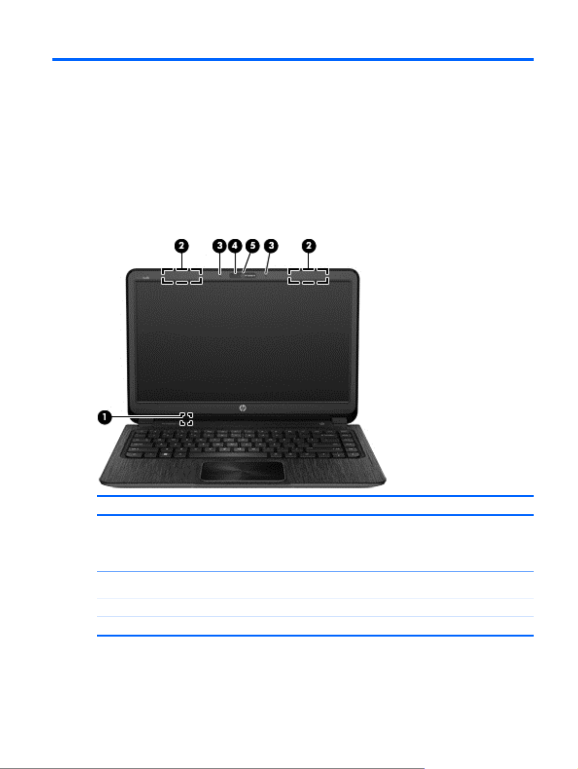
2 External component identification
Display
Component Description
(1) Internal display switch Turns off the display and initiates Sleep/Suspend if the display
(2) WLAN antennas (2)* Send and receive wireless signals to communicate with wireless
(3) Internal microphones (2) Record sound.
(4) Webcam light On: The webcam is in use.
is closed while the power is on.
NOTE: The internal display switch is not visible from the
outside of the computer.
local area networks (WLANs).
Display 5
Page 14
Component Description
(5) HP TrueVision HD Webcam Records video, captures still photographs, and allows video
*The antennas are not visible from the outside of the computer. For optimal transmission, keep the areas immediately
around the antennas free from obstructions. For wireless regulatory notices, see the section of the Regulatory, Safety and
Environmental Notices that applies to your country or region.
conferences and online chat by means of streaming video.
To use the webcam in Windows 8, from the Start screen, type
c, and then select CyberLink YouCam.
For details about using your webcam in Ubuntu Linux, click the
Help menu in the guvcview software.
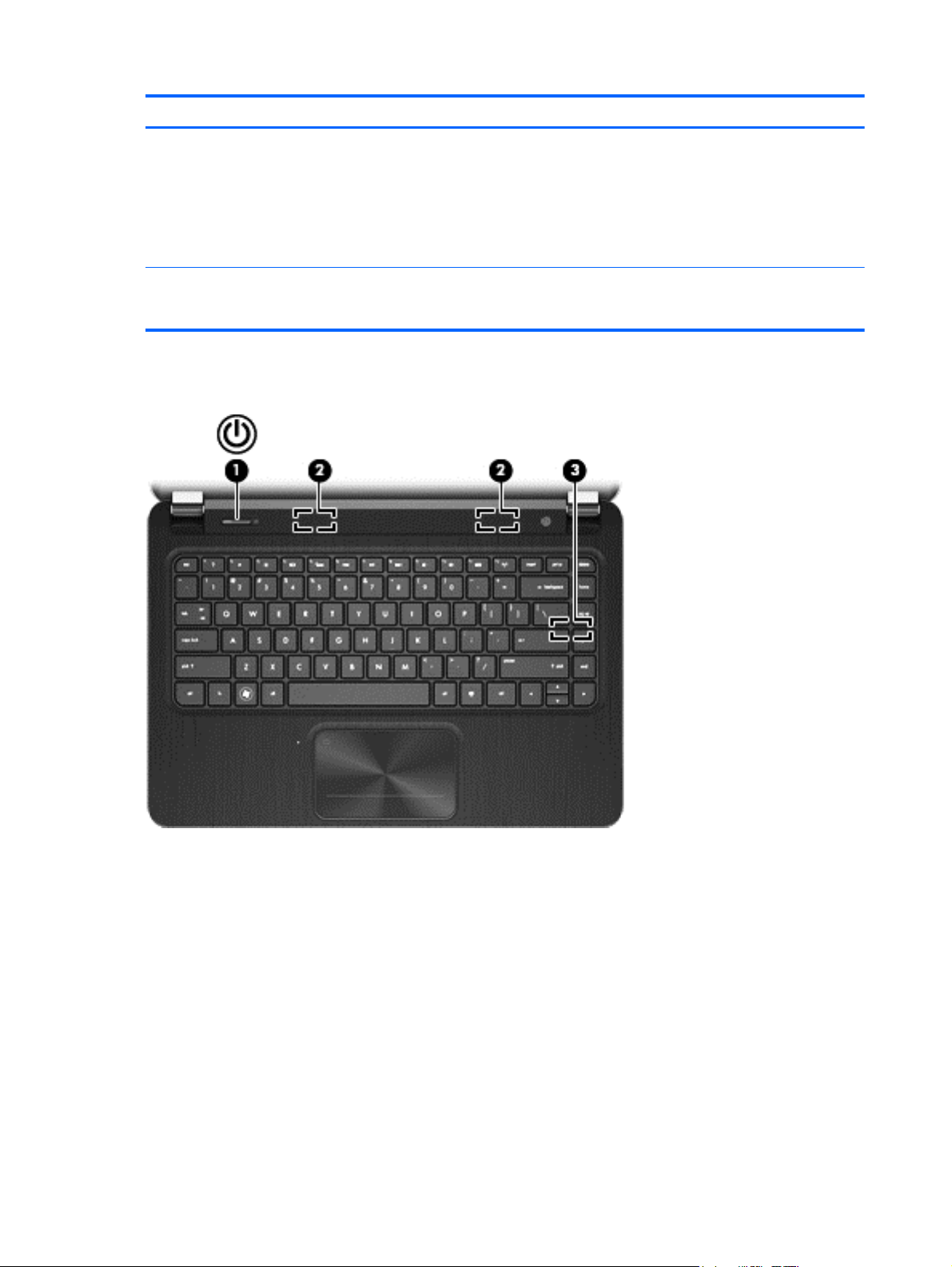
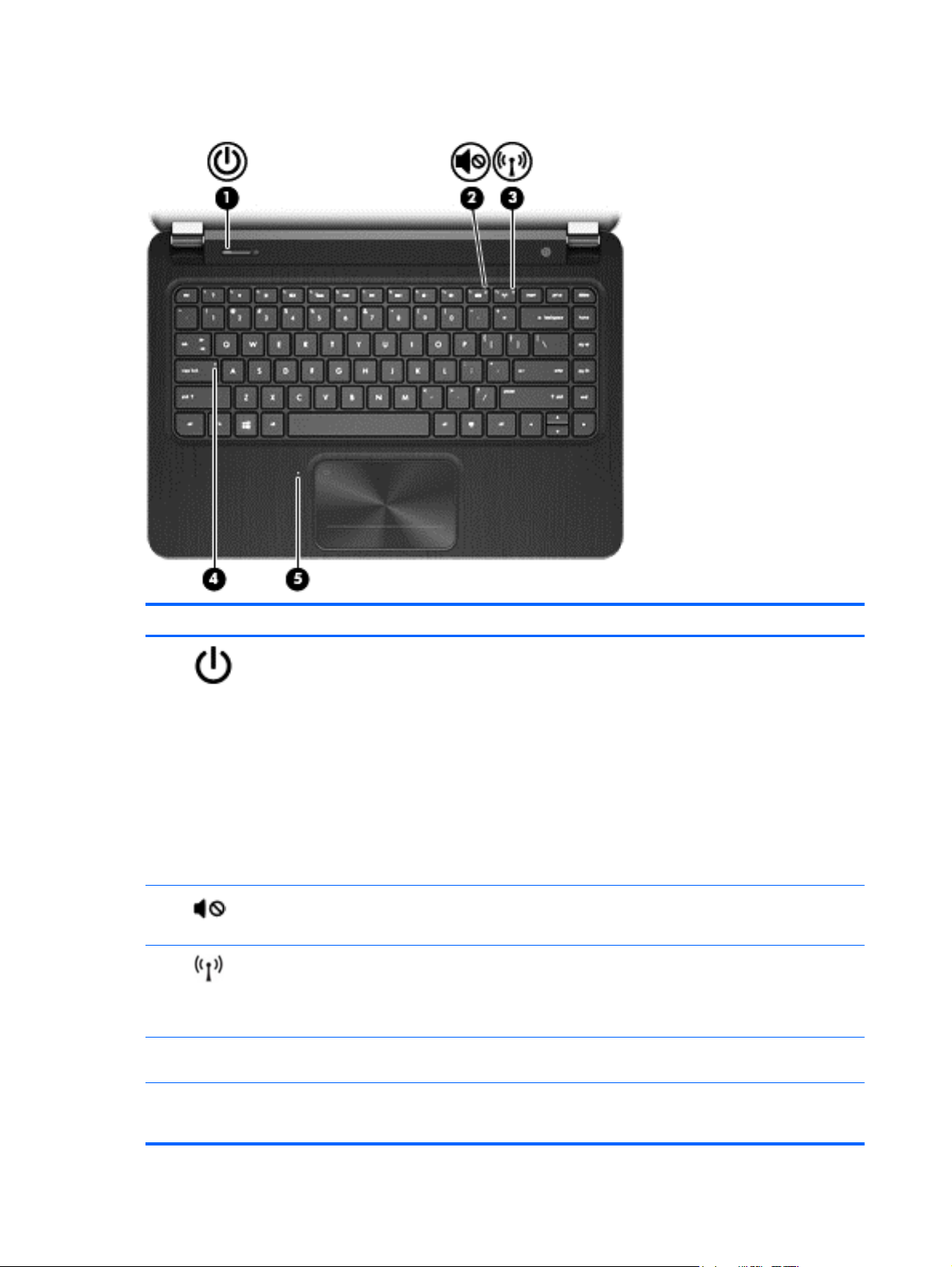
Button, speakers, and subwoofer
6 Chapter 2 External component identification
Page 15

Component Description
(1)
Power button
When the computer is off, press the button to turn on
●
the computer.
● When the computer is in the Sleep/Suspend state,
press the button briefly to exit Sleep/Suspend.
When the computer is in Hibernation, press the button
●
down briefly to exit Hibernation
CAUTION: Pressing and holding down the power button
will result in the loss of unsaved information.
If the computer has stopped responding and Microsoft®
Windows® shutdown procedures are ineffective, press and
hold the power button down for at least 5 seconds to turn
off the computer.
NOTE: For select models, the Intel® Rapid Start
Technology feature is enabled at the factory. Rapid Start
Technology allows your computer to resume quickly from
inactivity. For more information, see the User Guide.
To learn more about your power settings:
In Windows 8:
From the Start screen, type power, select Settings,
●
and then select Power options, or see the User
Guide.
In Ubuntu Linux:
Click the System menu icon at the far right of the top
●
panel, and then click System Settings > Power icon.
(2) Speakers (2) Produce sound.
(3) HP Triple Bass Reflex Subwoofer Provides superior bass sound.
Button, speakers, and subwoofer 7
Page 16
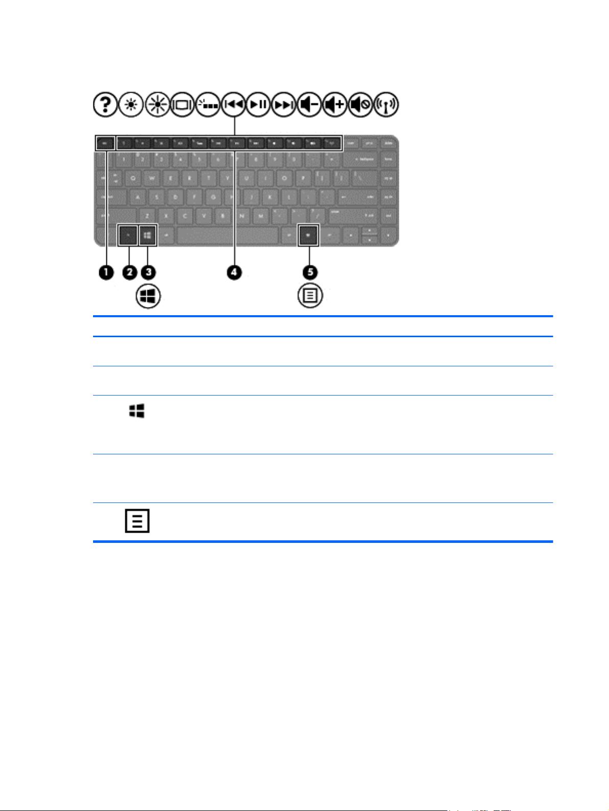
Keys — Windows 8 models
Component Description
(1) esc key Displays system information when pressed in combination
(2) fn key Executes frequently used system functions when pressed
(3)
(4) Action keys Execute frequently used system functions.
(5)
Windows 8 logo key Returns you to the Start screen from an open app or the
Windows 8 applications key Displays a shortcut menu for a selected object.
with the fn key.
in combination with the b key or the esc key.
Windows desktop.
NOTE: Pressing the Windows logo key again will return
you to the previous screen.
NOTE: On select models, the f5 action key turns the
radiance backlight keyboard feature off or on.
8 Chapter 2 External component identification
Page 17
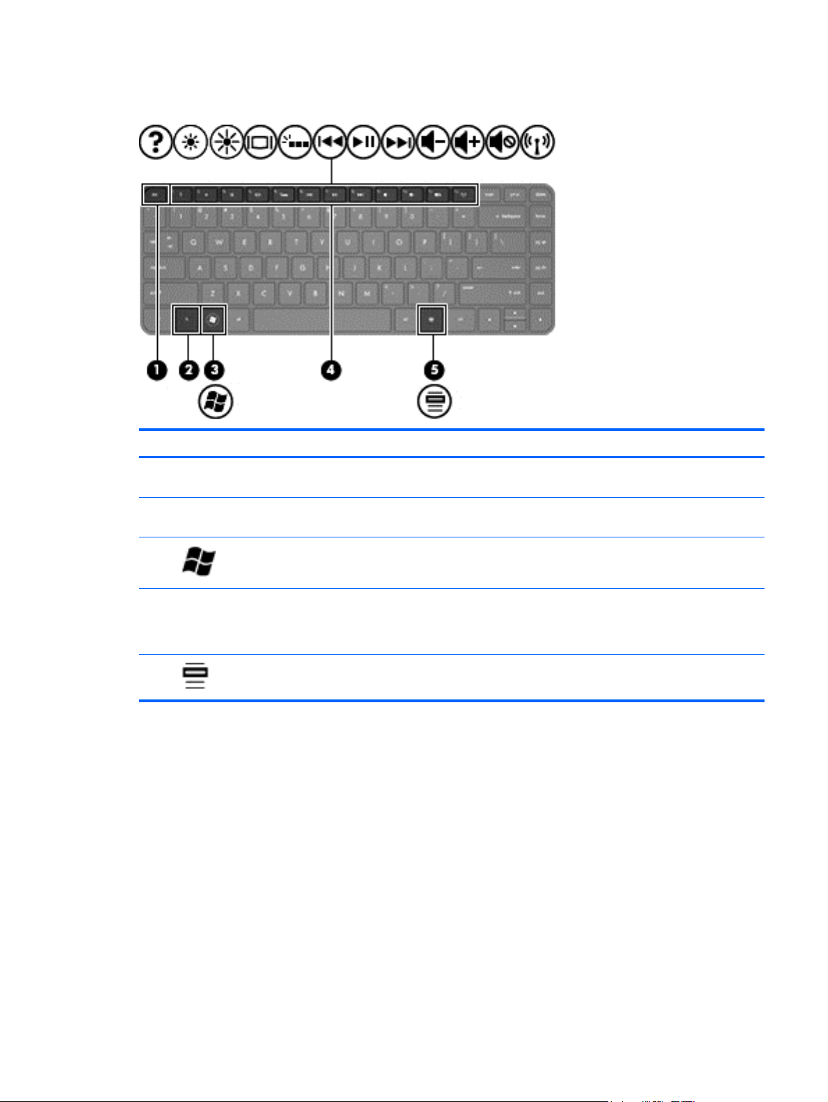
Keys — Ubuntu Linux models
Component Description
(1) esc key Displays system information when pressed in combination
(2) fn key Executes frequently used system functions when pressed
(3)
(4) Action keys Execute frequently used system functions.
(5)
Operating system logo key Displays the operating system menu.
Operating system applications key Displays a shortcut menu for items beneath the cursor.
with the fn key.
in combination with the b key or the esc key.
NOTE: On select models, the f5 action key turns the
radiance backlight keyboard feature off or on.
Keys — Ubuntu Linux models 9
Page 18
Lights
Component Description
(1)
(2)
(3)
(4) Caps lock light On: Caps lock is on, which switches the keys to all capital
Power light
Mute light ● Amber: Computer sound is off.
Wireless light ● White: An integrated wireless device, such as a
White: The computer is on.
●
● Blinking white: The computer is in the Sleep/Suspend
state, which is an energy-saving mode. The computer
shuts off power to the display and other unneeded
components.
● Off: The computer is off or in Hibernation. Hibernation
is an energy-saving mode that uses the least amount
of power.
NOTE: For select models, the Intel® Rapid Start
Technology feature is enabled at the factory.
RapidStart Technology allows your computer to
resume quickly from inactivity.
Off: Computer sound is on.
●
wireless local area network (WLAN) device and/or a
Bluetooth® device, is on.
● Amber: All wireless devices are off.
letters.
(5) TouchPad light
10 Chapter 2 External component identification
On: The TouchPad is off.
●
● Off: The TouchPad is on.
Page 19
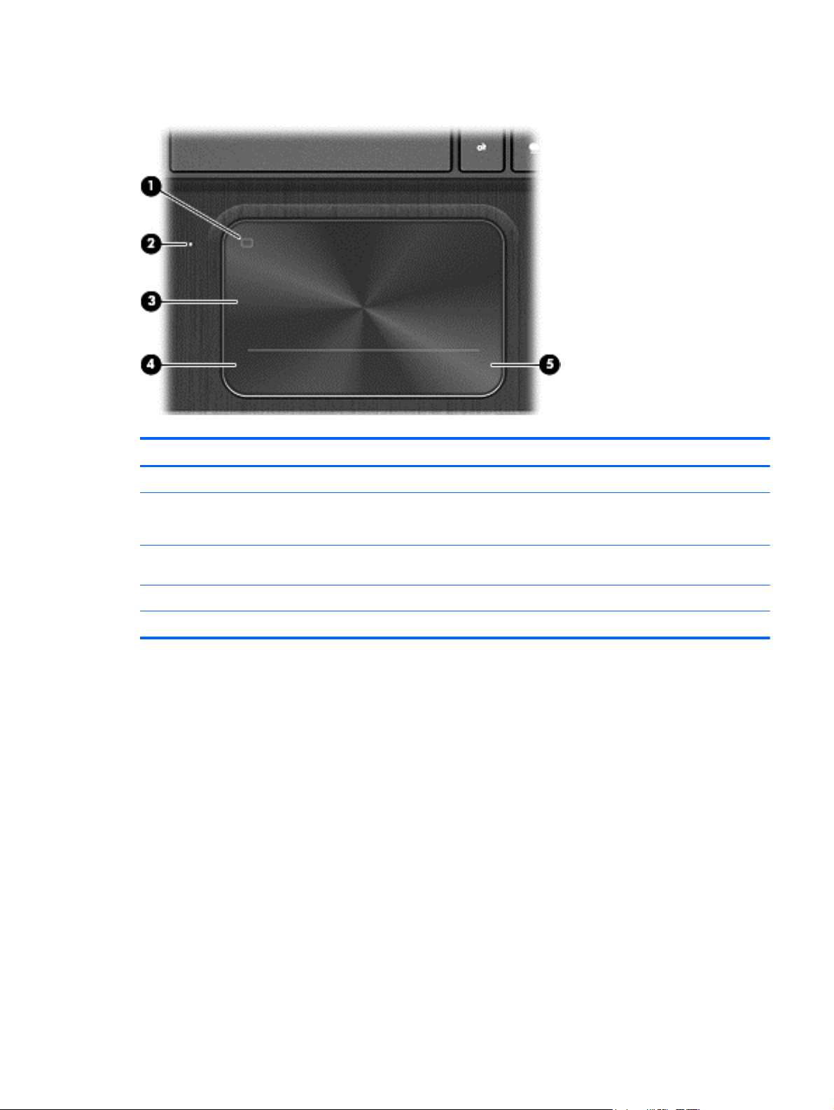
TouchPad
Component Description
(1) TouchPad on/off button Turns the TouchPad on or off.
(2) TouchPad light
(3) TouchPad zone Moves the on-screen pointer and selects or activates items
(4) Left TouchPad button Functions like the left button on an external mouse.
(5) Right TouchPad button Functions like the right button on an external mouse.
On: The TouchPad is off.
●
● Off: The TouchPad is on.
on the screen.
TouchPad 11
Page 20
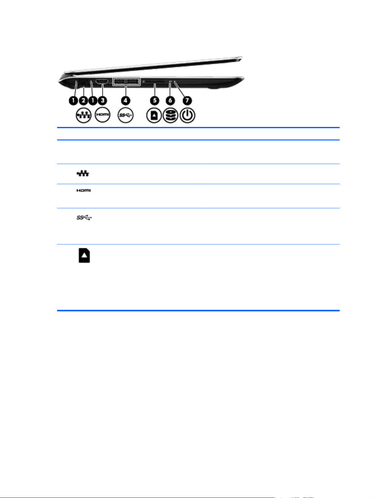
Left side
Component Description
(1) RJ-45 (network) status lights (2)
(2)
(3)
(4)
(5)
RJ-45 (network) jack Connects a network cable.
HDMI port Connects an optional video or audio device, such as a
USB 3.0 ports (2) Connect optional USB 3.0 devices and provide enhanced
Digital Media slot Supports the following digital card formats:
White (left): The network is connected.
●
● Amber (right): Activity is occurring on the network.
high-definition television, or any compatible digital or audio
device.
USB power performance.
NOTE: For details about different types of USB ports, see
the User Guide.
● Secure Digital (SD) Memory Card
Secure Digital High Capacity (SDHC) Memory Card
●
Secure Digital Extended Capacity (SDxC) Memory
●
Card
Ultra High Speed MultiMediaCard (UHS/MMC)
●
12 Chapter 2 External component identification
Page 21

Component Description
(6)
(7)
Hard drive light
Power light
Blinking white: The hard drive is being accessed.
●
● Amber: HP 3D DriveGuard has temporarily parked the
hard drive.
NOTE: For information about HP 3D DriveGuard,
see the User Guide.
White: The computer is on.
●
● Blinking white: The computer is in the Sleep/Suspend
state, which is an energy-saving mode. The computer
shuts off power to the display and other unneeded
components.
● Off: The computer is off or in Hibernation. Hibernation
is an energy-saving mode that uses the least amount
of power.
NOTE: For select models, the Intel® Rapid Start
Technology feature is enabled at the factory.
RapidStart Technology allows your computer to
resume quickly from inactivity.
Left side 13
Page 22
Right side
Component Description
(1)
(2)
(3)
(4)
Security cable slot Attaches an optional security cable to the computer.
NOTE: The security cable is designed to act as a
deterrent, but it may not prevent the computer from being
mishandled or stolen.
Audio-in (microphone) jack Connects an optional computer headset microphone, stereo
array microphone, or monaural microphone.
Audio-out (headphone) jack Connects optional powered stereo speakers, headphones,
earbuds, a headset, or a television audio cable.
WARNING! To reduce the risk of personal injury, adjust
the volume before using headphones, earbuds, or a
headset. For additional safety information, see the
Regulatory, Safety and Environmental Notices.
NOTE: When a device is connected to a headphone jack,
the computer speakers are disabled.
USB 2.0 charging port Connects an optional USB device. The USB 2.0 charging
port can also charge select models of cell phones and MP3
players, even when the computer is off.
NOTE: A charging USB port (also referred to as a
powered USB port) allows you to charge connected USB
devices. Standard USB ports will not charge all USB
devices or will charge using a low current. Some USB
devices require power and require you to use a powered
port.
(5)
(6) Power connector Connects an AC adapter.
AC adapter light ● White: The AC adapter is connected and the battery is
14 Chapter 2 External component identification
NOTE: For details about different types of USB ports, see
the User Guide.
charged.
Amber: The AC adapter is connected and the battery
●
is charging.
Off: The computer is using DC power.
●
Page 23
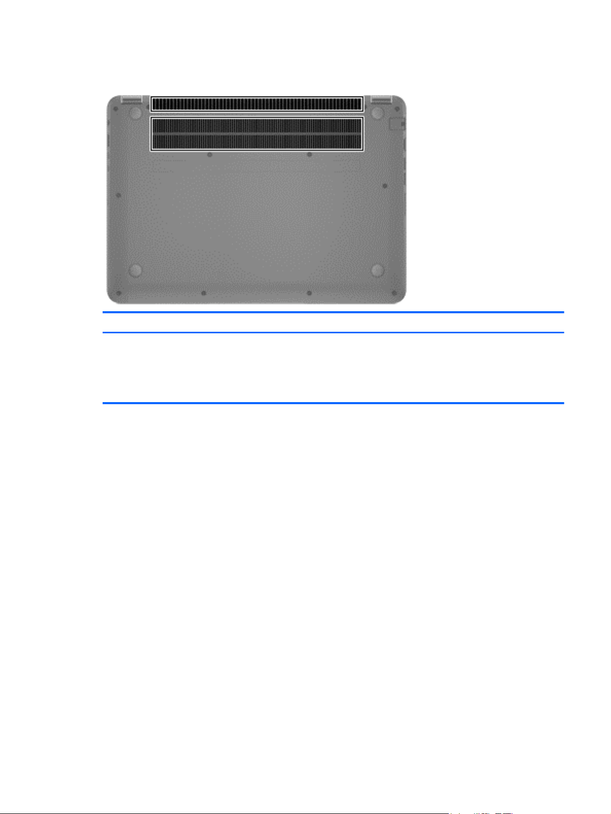
Bottom
Component Description
Vents (2) Enable airflow to cool internal components.
NOTE: The computer fan starts up automatically to cool
internal components and prevent overheating. It is normal
for the internal fan to cycle on and off during routine
operation.
Bottom 15
Page 24

16 Chapter 2 External component identification
Page 25
3 Illustrated parts catalog
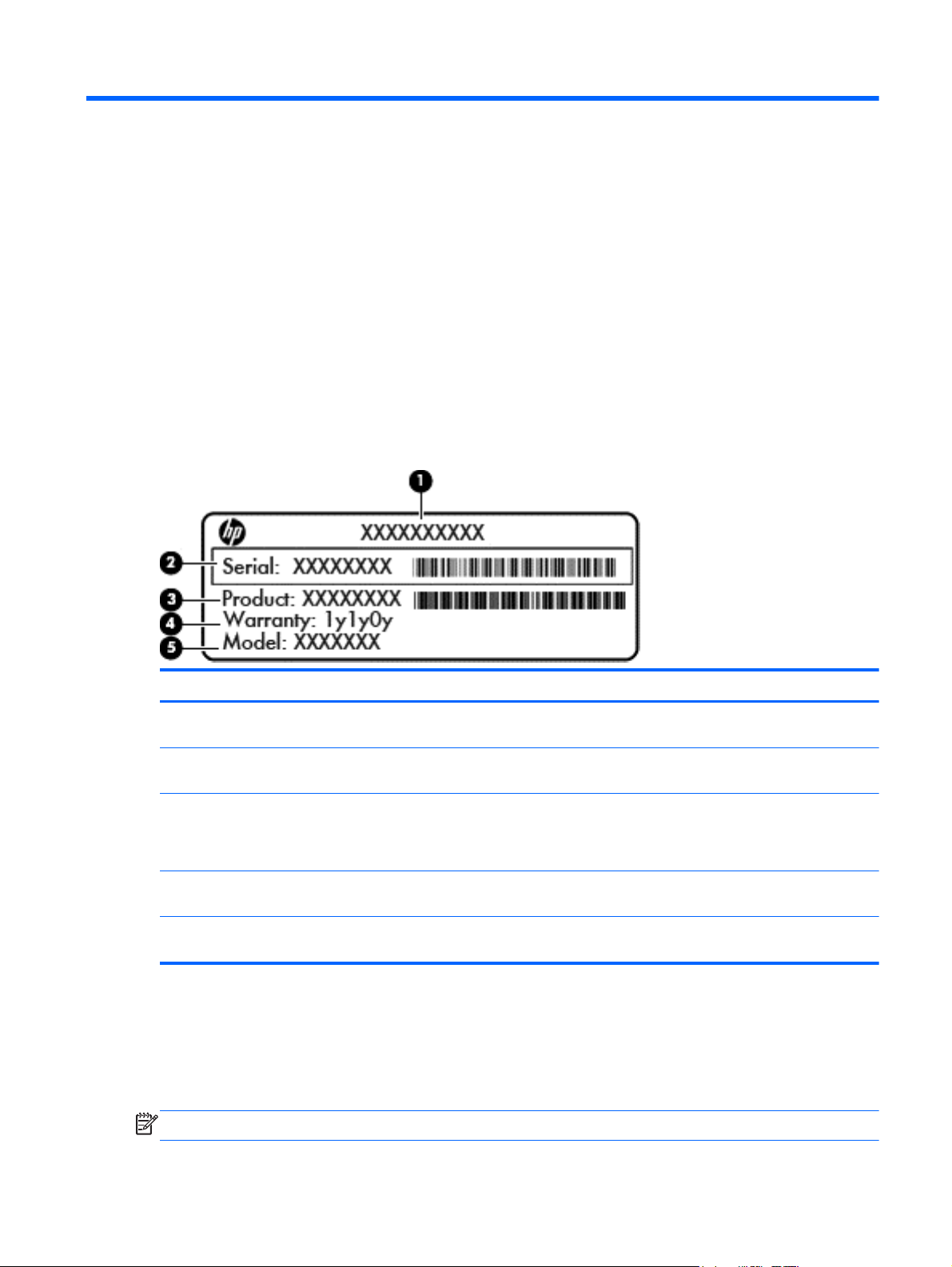
Service tag and PCID label
Service tag
When ordering parts or requesting information, provide the computer serial number and model
description provided on the service tag, which is located on the bottom of the computer.
Item Description Function
(1) Product name This is the product name affixed to the front of
(2) Serial number This is an alphanumeric identifier that is unique to
(3) Part number/Product number This number provides specific information about the
(4) Warranty period This number describes the duration of the warranty
(5) Model description (select models only) This is the alphanumeric identifier used to locate
PCID label
The PCID label provides the information required to properly reset the notebook firmware (BIOS)
back to factory shipped specifications when replacing the system board. The label may have a
different number of characters depending on the operating system on the computer.
NOTE: Computer details may vary from images.
the computer.
each product.
product's hardware components. The part number
helps a service technician to determine what
components and parts are needed.
period for the computer.
documents, drivers, and support for the computer.
Service tag and PCID label 17
Page 26
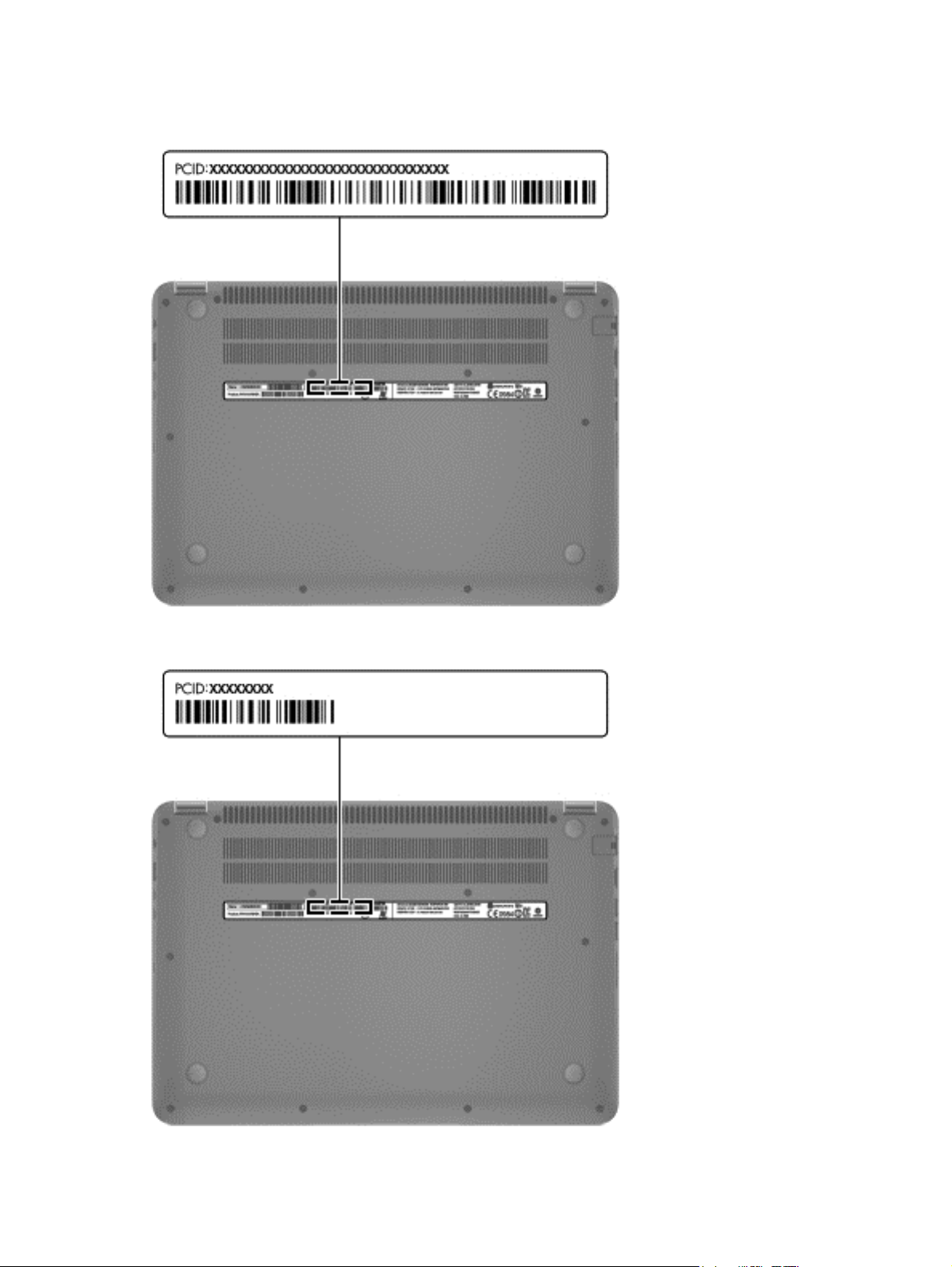
Windows 8 models
Non-Windows 8 models
18 Chapter 3 Illustrated parts catalog
Page 27
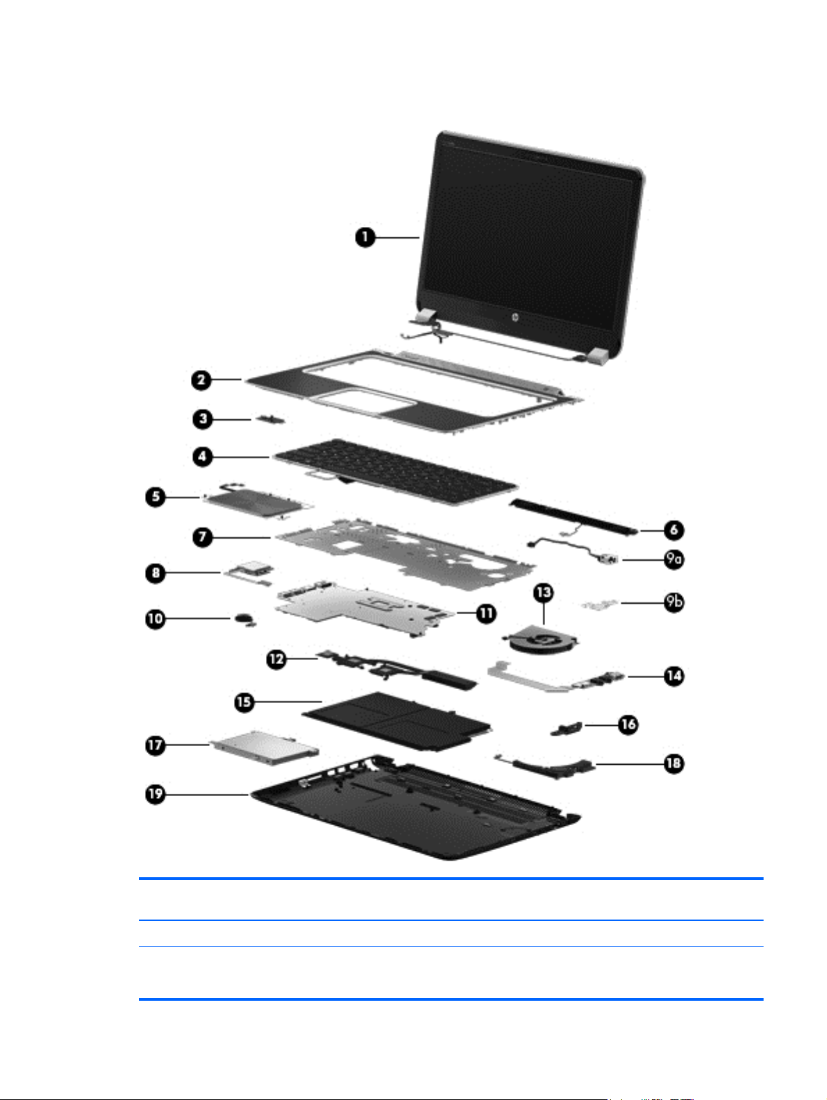
Computer major components
Item Component Spare part
number
(1) Display panel
In black finish for use with touch models only 699378-001
716398-001
Computer major components 19
Page 28

Item Component Spare part
number
In black finish for use with non-touch models only 702683-001
716399-001
In black and silver finish for use with non-touch models only 702684-001
716400-001
(2) Top cover 686093-001
690194-001
(3) Power button board (includes cable) 688000-001
(4) Keyboard (includes keyboard cable):
In black finish for use with Windows 8
For use in the United States 698679-001
For use in the United Kingdom and Singapore 698679-031
For use in Germany 698679-041
For use in France 698679-051
For use in Italy 698679-061
For use in Latin America 698679-161
For use in Thailand 698679-281
For use in Japan 698679-291
For use in Taiwan 698679-AB1
For use in Korea 698679-AD1
For use in the Netherlands 698679-B31
For use in Slovenia 698679-BA1
For use in India 698679-D61
For use in the Czech Republic 698679-FL1
Backlit keyboard in black finish for use with Windows 8
For use in the United States 698680-001
For use in Spain 698680-071
For use in Turkey 698680-141
For use in Latin America 698680-161
For use in Saudi Arabia 698680-171
For use in Russia 698680-251
For use in Belgium 698680-A41
For use in the Netherlands 698680-B31
For use in Switzerland 698680-BG1
20 Chapter 3 Illustrated parts catalog
Page 29

Item Component Spare part
number
For use in Canada 698680-DB1
For use in Denmark, Finland, Norway 698680-DH1
in black/silver finish for use with Windows 8
For use in the United States 698681-001
For use in the United Kingdom and Singapore 698681-031
For use in Germany 698681-041
For use in France 698681-051
For use in Italy 698681-061
For use in Latin America 698681-161
For use in Thailand 698681-281
For use in Japan 698681-291
For use in Taiwan 698681-AB1
For use in Korea 698681-AD1
For use in the Netherlands 698681-B31
For use in Slovenia 698681-BA1
For use in India 698681-D61
For use in the Czech Republic 698681-FL1
Backlit keyboard In black/silver finish for use with Windows 8
For use in the United States 698682-001
For use in Spain 698682-071
For use in Turkey 698682-141
For use in Latin America 698682-161
For use in Saudi Arabia 698682-171
For use in Brazil 698682-201
For use in Russia 698682-251
For use in Belgium 698682-A41
For use in the Netherlands 698682-B31
For use in Switzerland 698682-BG1
For use in Canada 698682-DB1
For use in Denmark, Finland, Norway 698682-DH1
(5) TouchPad button board (includes cable)
In black finish 687997-001
In silver finish 691640-001
(6) Speaker kit (includes subwoofer) 686585-001
Computer major components 21
Page 30

Item Component Spare part
number
(7) Keyboard bracket 687998-001
(8) Smart card reader 687097-001
For use with touch models only 702928-001
(9a) Power connector cable (includes bracket) 686577-001
(9b) Power connector cable bracket 686577-001
(10) RTC battery 686922-001
(11) System board
For non-touch models:
System board for use only with computer models equipped with an Intel 1.9 GHz processor
(includes processor and replacement thermal material).
System board for use only with computer models equipped with an Intel 1.9 GHz processor
and Windows 8 Standard (includes processor and replacement thermal material).
System board for use only with computer models equipped with an Intel 1.9 GHz processor
and Windows 8 Pro (includes processor and replacement thermal material).
System board for use only with computer models equipped with an Intel 1.8 GHz processor
(includes processor and replacement thermal material).
System board for use only with computer models equipped with an Intel 1.8 GHz processor
and Windows 8 Standard (includes processor and replacement thermal material).
713810-001
713814-001
713810-501
713814-501
713810-601
713814-601
686086-002
693657-001
708961-001
708966-001
712354-001
712355-001
713809-001
713813-001
716306-001
708966-501
712354-501
22 Chapter 3 Illustrated parts catalog
712355-501
713809-501
713813-501
716306-501
Page 31

Item Component Spare part
number
System board for use only with computer models equipped with an Intel 1.8 GHz processor
and Windows 8 Pro (includes processor and replacement thermal material).
System board for use only with computer models equipped with an Intel 1.7GHz processor
(includes processor and replacement thermal material).
System board for use only with computer models equipped with an Intel 1.7 GHz processor
and Windows 8 Standard (includes processor and replacement thermal material).
System board for use only with computer models equipped with an Intel 1.7 GHz processor
and Windows 8 Pro (includes processor and replacement thermal material).
System board for use only with computer models equipped with an Intel 1.6 GHz processor
(includes processor and replacement thermal material).
System board for use only with computer models equipped with an Intel 1.5 GHz processor
(includes processor and replacement thermal material).
708966-601
712354-601
712355-601
713809-601
713813-601
716306-601
686087-002
708963-001
716307-001
716307-501
716307-601
686089-002
686091-002
693655-001
693656-001
System board for use only with computer models equipped with an Intel 1.5 GHz processor
and Windows 8 Standard (includes processor and replacement thermal material)
System board for use only with computer models equipped with an Intel 1.5 GHz processor
and Windows 8 Pro (includes processor and replacement thermal material)
System board for use only with computer models equipped with an Intel 1.4GHz processor
(includes processor and replacement thermal material).
708964-001
708965-001
712356-001
716308-001
702922-501
708964-501
708965-501
712356-501
716308-501
702922-601
708964-601
708965-601
712356-601
716308-601
686088-002
System board for use only with computer models equipped with an Intel 1.4GHz processor
and Windows 8 Standard (includes processor and replacement thermal material).
Computer major components 23
686088-002
Page 32

Item Component Spare part
number
System board for use only with computer models equipped with an Intel 1.4GHz processor
and Windows 8 Pro (includes processor and replacement thermal material).
For non-touch models:
System board for use only with touch models equipped with an Intel 1.8 GHz processor
(includes replacement thermal material)
System board for use only with touch models equipped with an Intel 1.8 GHz processor and
Windows 8 Standard (includes replacement thermal material)
System board for use only with touch models equipped with an Intel 1.8 GHz processor and
Windows 8 Pro (includes replacement thermal material)
System board for use only with touch models equipped with an Intel 1.7 GHz processor
(includes processor and replacement thermal material)
System board for use only with touch models equipped with an Intel 1.7 GHz processor and
Windows 8 Standard (includes processor and replacement thermal material)
System board for use only with touch models equipped with an Intel 1.7 GHz processor and
Windows 8 Pro (includes processor and replacement thermal material)
(12) Fan—Heat sink 686578-001
686088-002
702925-001
702925-501
708961-501
702925-601
708961-601
702926-001
708962-001
702926-501
708962-501
702926-601
708962-601
686579-001
(13) Fan 691641-001
(14) USB/Audio board 686584-001
(15) Battery:
4-cell, 52 WHr 3.55AH Li-ion battery 681949-001
(16) Security lock 686577-001
(17) Hard drive (7mm SATA 2.5”)
320-GB, 7200-rpm hard drive 634862-005
320-GB, 5400-rpm hard drive 645193-005
320-GB, 5400-rpm hard drive 683802-005
(18) Subwoofer (included in Speaker Kit) 686586-001
(19) Base enclosure
Base enclosure in red finish 686092-001
Base enclosure in black finish 690193-001
Base enclosure for use with touch models only 702927-001
24 Chapter 3 Illustrated parts catalog
Page 33

Mass storage devices
Item Component Spare part number
(1) Hard drive (7mm SATA 2.5”)
320-GB, 7200-rpm hard drive 634862-005
320-GB, 5400-rpm hard drive 645193-005
500-GB 5400-rpm hard drive 683802-005
(2a) Hard drive bracket 686581-001
(2b) Hard drive cable 686581-001
(3) Hard drive (mSATA solid-state drive)
32-GB solid-state (SSD) drive 687100-001
24-GB solid-state (SSD) drive 717097-001
(4) Optical drive
Blu-ray ROM DVD±R/RW Super Multi Double-Layer Drive 659941-001
DVD±RW and CD-RW Super Multi Double-Layer Combo Drive 659940-001
Screws (not illustrated)
Mass storage devices 25
Page 34

Miscellaneous parts
Component Spare part number
AC adapter (non-smart):
65-W PFC RC V 2-wire AC adapter (non-smart) for use in all countries and regions 693715-001
65-W PFC 2-wire AC adapter (non-smart) for use in all countries and regions 707750-001
Power cord (3-pin, black, 1.83-m):
For use in North America 490371-001
For use in Australia 490371-011
For use in Europe 490371-021
For use in the United Kingdom and Singapore 490371-031
For use in Italy 490371-061
For use in Denmark, Finland, Norway 490371-081
For use in Switzerland 490371-111
For use in Thailand 490371-201
For use in Brazil 490371-202
For use in Japan 490371-291
For use in the People's Republic of China 490371-AA1
For use in Taiwan 490371-AB1
For use in South Korea 490371-AD1
For use in South Africa 490371-AR1
For use in Argentina 490371-D01
For use in India 490371-D61
Screw Kit 687098-001
26 Chapter 3 Illustrated parts catalog
Page 35

Sequential part number listing
Spare part
number
490371-001 Power cord for use in North America (3-pin, black, 1.83-m)
490371-011 Power cord for use in Australia (3-pin, black, 1.83-m)
490371-021 Power cord for use in Europe (3-pin, black, 1.83-m)
490371-031 Power cord for use in the United Kingdom and Singapore (3-pin, black, 1.83-m)
490371-061 Power cord for use in Italy (3-pin, black, 1.83-m)
490371-081 Power cord for use in Denmark, Finland, Norway (3-pin, black, 1.83-m)
490371-111 Power cord for use in Switzerland (3-pin, black, 1.83-m)
490371-201 Power cord for use in Thailand (3-pin, black, 1.83-m)
490371-202 Power cord for use in Brazil (3-pin, black, 1.83-m)
490371-291 Power cord for use in Japan (3-pin, black, 1.83-m)
490371-AA1 Power cord for use in the People's Republic of China (3-pin, black, 1.83-m)
490371-AB1 Power cord for use in Taiwan (3-pin, black, 1.83-m)
490371-AD1 Power cord for use in South Korea (3-pin, black, 1.83-m)
490371-AR1 Power cord for use in South Africa (3-pin, black, 1.83-m)
490371-D01 Power cord for use in Argentina (3-pin, black, 1.83-m)
Description
490371-D61 Power cord for use in India (3-pin, black, 1.83-m)
634862-005 320-GB, 7200-rpm hard drive
641369-005 4-GB memory module (PC3, 12800, 1600-MHz)
645193-005 320-GB, 5400-rpm hard drive
652972-005 2-GB memory module (PC3, 12800, 1600-MHz)
655795-005 Atheros 9485GN 802.11b/g/n 1×1 WiFi and 3012 Bluetooth 4.0 Combo Adapter
657325-005 Broadcom 4313GN 802.11b/g/n 1×1 WiFi and 20702 Bluetooth 4.0 Combo Adapter
659940-001 DVD±RW and CD-RW Super Multi Double-Layer Combo Drive
659941-001 Blu-ray ROM DVD±R/RW Super Multi Double-Layer Drive
670034-005 8-GB memory module (PC3, 12800, 1600-MHz)
670290-005 Intel® Centrino® Wireless-N 1030 + Bluetooth combo w/ *2 antennas (802.11 b/g/n, Bluetooth 3.0)
675794-005 802.11 b/g/n HMC 1×1 WiFi adapter
681949-001 4-cell, 50 WHr 4.1AH Li-ion battery
683802-005 500-GB, 5400-rpm hard drive
686086-002 System board for use only with computer models equipped with an Intel 1.8GHz processor (includes
686087-002 System board for use only with computer models equipped with an Intel 1.7GHz processor (includes
processor and replacement thermal material)
processor and replacement thermal material)
Sequential part number listing 27
Page 36

Spare part
number
Description
686088-002 System board for use only with computer models equipped with an Intel 1.4GHz processor (includes
686089-002 System board for use only with computer models equipped with an Intel 1.6GHz processor (includes
686090-002 System board for use only with computer models equipped with an Intel 1.4GHz processor (includes
686091-002 System board for use only with computer models equipped with an Intel 1.6GHz processor (includes
686092-001 Base enclosure in red finish
686093-001 Top cover in black finish (includes power button board and cable and TouchPad and TouchPad cable)
686573-001 WLAN antennas
686575-001 Display bezel
686577-001 Power connector (includes cable)
686578-001 Thermal module
686579-001 Thermal module
686581-001 Hardware kit (hard drive, includes cable)
686584-001 USB/Audio board
686585-001 Speaker kit (includes subwoofer)
processor and replacement thermal material)
processor and replacement thermal material)
processor and replacement thermal material)
processor and replacement thermal material)
686586-001 Subwoofer (included in Speaker kit)
686836-251 Keyboard in black finish for use in Russia (includes keyboard cable)
686922-001 RTC battery
687097-001 Smart card reader
687098-001 Screw kit
687100-001 32-GB solid-state drive only (does not include bracket, connector cable, isolators, or screws)
687997-001 TouchPad assembly (includes bracket) in black finish
687998-001 Keyboard bracket
688000-001 Power button board (includes cable)
689844-002 System board for use only with computer models equipped with an Intel 1.7GHz processor (includes
690019-005 Atheros AR9565 802.11 b/g/n 1×1 WiFi Adapter
690020-005 Ralink 802.11 b/g/n 1×1 WiFi + Bluetooth 4.0 Combo Adapter
690193-001 Base enclosure in black finish
690194-001 Top cover in silver finish
691640-001 TouchPad assembly (includes bracket) in silver finish
691641-001 Fan (with foil)
processor and replacement thermal material)
692758-251 Keyboard in black or silver finish for use in Russia (includes keyboard cable)
28 Chapter 3 Illustrated parts catalog
Page 37

Spare part
number
Description
693655-001 System board for use only with computer models equipped with an Intel 1.5GHz processor (includes
693656-001 System board for use only with computer models equipped with an Intel 1.5GHz processor (includes
693657-001 System board for use only with computer models equipped with an Intel 1.8GHz processor (includes
693715-001 AC Adapter (non-smart) 65 W RC V 2-wire for use in all countries and regions except India
698679-001 Keyboard in black finish for use with computer models with Windows 8 in the United States (includes
698679-031 Keyboard in black finish for use with computer models with Windows 8 in the United Kingdom and
698679-041 Keyboard in black finish for use with computer models with Windows 8 in Germany (includes keyboard
698679-051 Keyboard in black finish for use with computer models with Windows 8 France (includes keyboard
698679-061 Keyboard in black finish for use with computer models with Windows 8 in Italy (includes keyboard
698679-161 Keyboard in black finish for use with computer models with Windows 8 in Latin America (includes
698679-281 Keyboard in black finish for use with computer models with Windows 8 in Thailand (includes keyboard
processor and replacement thermal material)
processor and replacement thermal material)
processor and replacement thermal material)
keyboard cable)
Singapore (includes keyboard cable)
cable)
cable)
cable)
keyboard cable)
cable)
698679-291 Keyboard in black finish for use with computer models with Windows 8 in Japan (includes keyboard
698679-AB1 Keyboard in black finish for use with computer models with Windows 8 in Taiwan (includes keyboard
698679-AD1 Keyboard in black finish for use with computer models with Windows 8 in Korea (includes keyboard
698679-B31 Keyboard in black finish for use with computer models with Windows 8 in the Netherlands (includes
698679-BA1 Keyboard in black finish for use with computer models with Windows 8 in Slovenia (includes keyboard
698679-D61 Keyboard in black finish for use with computer models with Windows 8 in India (includes keyboard
698679-FL1 Keyboard in black finish for use with computer models with Windows 8 in the Czech Republic (includes
698680-001 Backlit keyboard in black finish for use with computer models with Windows 8 in the United States
698680-071 Backlit keyboard in black finish for use with computer models with Windows 8 in Spain (includes
698680-141 Backlit keyboard in black finish for use with computer models with Windows 8 in Turkey (includes
698680-161 Backlit keyboard in black finish for use with computer models with Windows 8 in Latin America
cable)
cable)
cable)
keyboard cable)
cable)
cable)
keyboard cable)
(includes keyboard cable)
keyboard cable)
keyboard cable)
(includes keyboard cable)
Sequential part number listing 29
Page 38

Spare part
number
Description
698680-171 Backlit keyboard in black finish for use with computer models with Windows 8 in Saudi Arabia
698680-251 Backlit keyboard in black finish for use with computer models with Windows 8 in Russia (includes
698680-A41 Backlit keyboard in black finish for use with computer models with Windows 8 in Belgium (includes
698680-B31 Backlit keyboard in black finish for use with computer models with Windows 8 in the Netherlands
698680-BG1 Backlit keyboard in black finish for use with computer models with Windows 8 in Swit5zerland
698680-DB1 Backlit keyboard in black finish for use with computer models with Windows 8 in Canada (includes
698680-DH1 Backlit keyboard in black finish for use with computer models with Windows 8 in Denmark, Finland,
698681-001 Keyboard in black/silver finish for use with computer models with Windows 8 in the United States
698681-031 Keyboard in black/silver finish for use with computer models with Windows 8 in the United Kingdom
698681-041 Keyboard in black/silver finish for use with computer models with Windows 8 in Germany (includes
698681-051 Keyboard in black/silver finish for use with computer models with Windows 8 in France (includes
(includes keyboard cable)
keyboard cable)
keyboard cable)
(includes keyboard cable)
(includes keyboard cable)
keyboard cable)
Norway (includes keyboard cable)
(includes keyboard cable)
and Singapore (includes keyboard cable)
keyboard cable)
keyboard cable)
698681-061 Keyboard in black/silver finish for use with computer models with Windows 8 in Italy (includes
698681-161 Keyboard in black/silver finish for use with computer models with Windows 8 in Latin America
698681-281 Keyboard in black/silver finish for use with computer models with Windows 8 in Thailand (includes
698681-291 Keyboard in black/silver finish for use with computer models with Windows 8 in Japan (includes
698681-AB1 Keyboard in black/silver finish for use with computer models with Windows 8 in Taiwan (includes
698681-AD1 Keyboard in black/silver finish for use with computer models with Windows 8 in Korea (includes
698681-B31 Keyboard in black/silver finish for use with computer models with Windows 8 in the Netherlands
698681-BA1 Keyboard in black/silver finish for use with computer models with Windows 8 in Slovenia (includes
698681-D61 Keyboard in black/silver finish for use with computer models with Windows 8 in India (includes
698681-FL1 Keyboard in black/silver finish for use with computer models with Windows 8 in the Czech Republic
698682-001 Backlit keyboard in black/silver finish for use with computer models with Windows 8 in the United
keyboard cable)
(includes keyboard cable)
keyboard cable)
keyboard cable)
keyboard cable)
keyboard cable)
(includes keyboard cable)
keyboard cable)
keyboard cable)
(includes keyboard cable)
States (includes keyboard cable)
30 Chapter 3 Illustrated parts catalog
Page 39

Spare part
number
Description
698682-071 Backlit keyboard in black/silver finish for use with computer models with Windows 8 in Spain (includes
698682-141 Backlit keyboard in black/silver finish for use with computer models with Windows 8 in Turkey
698682-161 Backlit keyboard in black/silver finish for use with computer models with Windows 8 in Latin America
698682-171 Backlit keyboard in black/silver finish for use with computer models with Windows 8 in Saudi Arabia
698682-201 Backlit keyboard in black/silver finish for use with computer models with Windows 8 in Brazil (includes
698682-251 Backlit keyboard in black/silver finish for use with computer models with Windows 8 in Russia
698682-A41 Backlit keyboard in black/silver finish for use with computer models with Windows 8 in Belgium
698682-B31 Backlit keyboard in black/silver finish for use with computer models with Windows 8 in the Netherlands
698682-BG1 Backlit keyboard in black/silver finish for use with computer models with Windows 8 in Switzerland
698682-DB1 Backlit keyboard in black/silver finish for use with computer models with Windows 8 in Canada
698682-DH1 Backlit keyboard in black/silver finish for use with computer models with Windows 8 in Denmark,
keyboard cable)
(includes keyboard cable)
(includes keyboard cable)
(includes keyboard cable)
keyboard cable)
(includes keyboard cable)
(includes keyboard cable)
(includes keyboard cable)
(includes keyboard cable)
(includes keyboard cable)
Finland, Norway (includes keyboard cable)
699378-001 Display panel for use with touch models only
699379-001 Hard drive hardware kit
699834-201 Atheros HB125 802.11 b/g/n 1×1 WiFi + Bluetooth 4.0 Combo Adapter for use in Brazil
702683-001 Display panel in black finish for use with non-touch computer models
702684-001 Display panel in black and silver finish for use with non-touch computer models
702925-001 System board for use only with computer models equipped with an Intel 1.8 GHz processor and
Windows 8 Standard (includes processor and replacement thermal material)
702925-501 System board for use only with computer models equipped with an Intel 1.8 GHz processor and
Windows 8 Standard (includes processor and replacement thermal material)
702925-601 System board for use only with computer models equipped with an Intel 1.8 GHz processor and
Windows 8 Professional (includes processor and replacement thermal material)
702926-001 System board for use only with computer models equipped with an Intel 1.7 GHz processor and
Windows 8 Standard (includes processor and replacement thermal material)
702926-501 System board for use only with computer models equipped with an Intel 1.7 GHz processor and
Windows 8 Standard (includes processor and replacement thermal material)
702926-601 System board for use only with computer models equipped with an Intel 1.7 GHz processor and
Windows 8 Professional (includes processor and replacement thermal material)
702927-001 Base enclosure for use with touch models only
702928-001 Smart card reader for use only with touch models only
Sequential part number listing 31
Page 40

Spare part
number
707750-001 AC Adapter (non-smart) 65 W RC V 2-wire for use in all countries and regions except India
Description
708961-001 For use only with computer models equipped with an Intel 1.8 GHz processor (includes replacement
708961-501 For use only with computer models equipped with an Intel 1.8 GHz processor and Windows 8
708961-601 For use only with computer models equipped with an Intel 1.8 GHz processor and Windows 8 Pro
708962-001 For use only with computer models equipped with an Intel 1.7 GHz processor (includes processor and
708962-501 For use only with computer models equipped with an Intel 1.7 GHz processor and Windows 8
708962-601 For use only with computer models equipped with an Intel 1.7 GHz processor and Windows 8 Pro
708963-001 For use only with computer models equipped with an Intel 1.7 GHz processor (includes processor and
708963-501 For use only with computer models equipped with an Intel 1.7 GHz processor and Windows 8
708963-601 For use only with computer models equipped with an Intel 1.7 GHz processor and Windows 8 Pro
708964-001 For use only with computer models equipped with an Intel 1.5 GHz processor (includes processor and
708964-501 For use only with computer models equipped with an Intel 1.5 GHz processor and Windows 8
thermal material)
Standard (includes replacement thermal material)
(includes replacement thermal material)
replacement thermal material)
Standard (includes processor and replacement thermal material)
(includes processor and replacement thermal material)
replacement thermal material)
Standard (includes processor and replacement thermal material)
(includes processor and replacement thermal material)
replacement thermal material)
Standard (includes processor and replacement thermal material)
708964-601 For use only with computer models equipped with an Intel 1.5 GHz processor and Windows 8 Pro
708965-001 For use only with computer models equipped with an Intel 1.5 GHz processor (includes processor and
708965-501 For use only with computer models equipped with an Intel 1.5 GHz processor and Windows 8
708965-601 For use only with computer models equipped with an Intel 1.5 GHz processor and Windows 8 Pro
708966-001 For use only with computer models equipped with an Intel 1.8 GHz processor (includes processor and
708966-501 For use only with computer models equipped with an Intel 1.8 GHz processor and Windows 8
708966-601 For use only with computer models equipped with an Intel 1.8 GHz processor and Windows 8 Pro
712354-001 For use only with computer models equipped with an Intel 1.7 GHz processor (includes processor and
712354-501 For use only with computer models equipped with an Intel 1.7 GHz processor and Windows 8
712354-601 For use only with computer models equipped with an Intel 1.7 GHz processor and Windows 8 Pro
(includes processor and replacement thermal material)
replacement thermal material)
Standard (includes processor and replacement thermal material)
(includes processor and replacement thermal material)
replacement thermal material)
Standard (includes processor and replacement thermal material)
(includes processor and replacement thermal material)
replacement thermal material)
Standard (includes processor and replacement thermal material)
(includes processor and replacement thermal material)
32 Chapter 3 Illustrated parts catalog
Page 41

Spare part
number
Description
712355-001 For use only with computer models equipped with an Intel 1.8 GHz processor (includes processor and
712355-501 For use only with computer models equipped with an Intel 1.8 GHz processor and Windows 8
712355-601 For use only with computer models equipped with an Intel 1.8 GHz processor and Windows 8 Pro
712356-001 For use only with computer models equipped with an Intel 1.5 GHz processor (includes processor and
712356-501 For use only with computer models equipped with an Intel 1.5 GHz processor and Windows 8
712356-601 For use only with computer models equipped with an Intel 1.5 GHz processor and Windows 8 Pro
713809-001 For use only with computer models equipped with an Intel 1.8 GHz processor (includes processor and
713809-501 For use only with computer models equipped with an Intel 1.8 GHz processor and Windows 8
713809-601 For use only with computer models equipped with an Intel 1.8 GHz processor and Windows 8 Pro
713810-001 For use only with computer models equipped with an Intel 1.9 GHz processor (includes processor and
713810-501 For use only with computer models equipped with an Intel 1.9 GHz processor and Windows 8
replacement thermal material)
Standard (includes processor and replacement thermal material)
(includes processor and replacement thermal material)
replacement thermal material)
Standard (includes processor and replacement thermal material)
(includes processor and replacement thermal material)
replacement thermal material)
Standard (includes processor and replacement thermal material)
(includes processor and replacement thermal material)
replacement thermal material)
Standard (includes processor and replacement thermal material)
713810-601 For use only with computer models equipped with an Intel 1.9 GHz processor and Windows 8 Pro
713813-001 For use only with computer models equipped with an Intel 1.8 GHz processor (includes processor and
713813-501 For use only with computer models equipped with an Intel 1.8 GHz processor and Windows 8
713813-601 For use only with computer models equipped with an Intel 1.8 GHz processor and Windows 8 Pro
713814-001 For use only with computer models equipped with an Intel 1.9 GHz processor (includes processor and
713814-501 For use only with computer models equipped with an Intel 1.9 GHz processor and Windows 8
713814-601 For use only with computer models equipped with an Intel 1.9 GHz processor and Windows 8 Pro
716306-001 For use only with computer models equipped with an Intel 1.8 GHz processor (includes processor and
716306-501 For use only with computer models equipped with an Intel 1.8 GHz processor and Windows 8
716306-601 For use only with computer models equipped with an Intel 1.8 GHz processor and Windows 8 Pro
716307-001 For use only with computer models equipped with an Intel 1.87 GHz processor (includes processor
(includes processor and replacement thermal material)
replacement thermal material)
Standard (includes processor and replacement thermal material)
(includes processor and replacement thermal material)
replacement thermal material)
Standard (includes processor and replacement thermal material)
(includes processor and replacement thermal material)
replacement thermal material)
Standard (includes processor and replacement thermal material)
(includes processor and replacement thermal material)
and replacement thermal material)
Sequential part number listing 33
Page 42

Spare part
number
Description
716307-501 For use only with computer models equipped with an Intel 1.7 GHz processor and Windows 8
716307-601 For use only with computer models equipped with an Intel 1.7 GHz processor and Windows 8 Pro
716308-001 For use only with computer models equipped with an Intel 1.5 GHz processor (includes processor and
716308-501 For use only with computer models equipped with an Intel 1.5 GHz processor and Windows 8
716308-601 For use only with computer models equipped with an Intel 1.5 GHz processor and Windows 8 Pro
716398-001 Display panel In black finish for use with touch models only
716399-001 Display panel in black finish for use with non-touch models only
716400-001 Display panel in black and silver finish for use with non-touch models only
717097-001 24-GB mSATA solid-state drive (SSD)
Standard (includes processor and replacement thermal material)
(includes processor and replacement thermal material)
replacement thermal material)
Standard (includes processor and replacement thermal material)
(includes processor and replacement thermal material)
34 Chapter 3 Illustrated parts catalog
Page 43

4 Removal and replacement procedures
CAUTION: This computer does not have user-replaceable parts. Only HP authorized service
providers should perform the removal and replacement procedures described here. Accessing the
internal part could damage the computer or void the warranty.
Preliminary replacement requirements
Tools required
You will need the following tools to complete the removal and replacement procedures:
Flat-bladed screwdriver
●
Magnetic screwdriver
●
Phillips P0 and P1 screwdrivers
●
Service considerations
The following sections include some of the considerations that you must keep in mind during
disassembly and assembly procedures.
NOTE: As you remove each subassembly from the computer, place the subassembly (and all
accompanying screws) away from the work area to prevent damage.
Plastic parts
CAUTION: Using excessive force during disassembly and reassembly can damage plastic parts.
Use care when handling the plastic parts. Apply pressure only at the points designated in the
maintenance instructions.
Cables and connectors
CAUTION: When servicing the computer, be sure that cables are placed in their proper locations
during the reassembly process. Improper cable placement can damage the computer.
Cables must be handled with extreme care to avoid damage. Apply only the tension required to
unseat or seat the cables during removal and insertion. Handle cables by the connector whenever
possible. In all cases, avoid bending, twisting, or tearing cables. Be sure that cables are routed in
such a way that they cannot be caught or snagged by parts being removed or replaced. Handle flex
cables with extreme care; these cables tear easily.
Preliminary replacement requirements 35
Page 44

Drive handling
CAUTION: Drives are fragile components that must be handled with care. To prevent damage to
the computer, damage to a drive, or loss of information, observe these precautions:
Before removing or inserting a hard drive, shut down the computer. If you are unsure whether
the computer is off or in Hibernation, turn the computer on, and then shut it down through the
operating system.
Before handling a drive, be sure that you are discharged of static electricity. While handling a drive,
avoid touching the connector.
Before removing a diskette drive or optical drive, be sure that a diskette or disc is not in the drive and
be sure that the optical drive tray is closed.
Handle drives on surfaces covered with at least one inch of shock-proof foam.
Avoid dropping drives from any height onto any surface.
After removing a hard drive, an optical drive, or a diskette drive, place it in a static-proof bag.
Avoid exposing an internal hard drive to products that have magnetic fields, such as monitors
or speakers.
Avoid exposing a drive to temperature extremes or liquids.
If a drive must be mailed, place the drive in a bubble pack mailer or other suitable form of protective
packaging and label the package “FRAGILE.”
Grounding guidelines
Electrostatic discharge damage
Electronic components are sensitive to electrostatic discharge (ESD). Circuitry design and structure
determine the degree of sensitivity. Networks built into many integrated circuits provide some
protection, but in many cases, ESD contains enough power to alter device parameters or melt
silicon junctions.
A discharge of static electricity from a finger or other conductor can destroy static-sensitive devices or
microcircuitry. Even if the spark is neither felt nor heard, damage may have occurred.
An electronic device exposed to ESD may not be affected at all and can work perfectly throughout a
normal cycle. Or the device may function normally for a while, then degrade in the internal layers,
reducing its life expectancy.
CAUTION: To prevent damage to the computer when you are removing or installing internal
components, observe these precautions:
Keep components in their electrostatic-safe containers until you are ready to install them.
Before touching an electronic component, discharge static electricity by using the guidelines
described in this section.
Avoid touching pins, leads, and circuitry. Handle electronic components as little as possible.
If you remove a component, place it in an electrostatic-safe container.
The following table shows how humidity affects the electrostatic voltage levels generated by
different activities.
36 Chapter 4 Removal and replacement procedures
Page 45

CAUTION: A product can be degraded by as little as 700 V.
Relative humidity
Event 10% 40% 55%
Walking across carpet 35,000 V 15,000 V 7,500 V
Walking across vinyl floor 12,000 V 5,000 V 3,000 V
Motions of bench worker 6,000 V 800 V 400 V
Removing DIPS from plastic tube 2,000 V 700 V 400 V
Removing DIPS from vinyl tray 11,500 V 4,000 V 2,000 V
Removing DIPS from Styrofoam 14,500 V 5,000 V 3,500 V
Removing bubble pack from PCB 26,500 V 20,000 V 7,000 V
Packing PCBs in foam-lined box 21,000 V 11,000 V 5,000 V
Packaging and transporting guidelines
Follow these grounding guidelines when packaging and transporting equipment:
Typical electrostatic voltage levels
● To avoid hand contact, transport products in static-safe tubes, bags, or boxes.
Protect ESD-sensitive parts and assemblies with conductive or approved containers or
●
packaging.
● Keep ESD-sensitive parts in their containers until the parts arrive at static-free workstations.
Place items on a grounded surface before removing items from their containers.
●
Always be properly grounded when touching a component or assembly.
●
Store reusable ESD-sensitive parts from assemblies in protective packaging or
●
nonconductive foam.
Use transporters and conveyors made of antistatic belts and roller bushings. Be sure that
●
mechanized equipment used for moving materials is wired to ground and that proper materials
are selected to avoid static charging. When grounding is not possible, use an ionizer to dissipate
electric charges.
Workstation guidelines
Follow these grounding workstation guidelines:
● Cover the workstation with approved static-shielding material.
Use a wrist strap connected to a properly grounded work surface and use properly grounded
●
tools and equipment.
● Use conductive field service tools, such as cutters, screwdrivers, and vacuums.
When fixtures must directly contact dissipative surfaces, use fixtures made only of static-
●
safe materials.
Preliminary replacement requirements 37
Page 46

Keep the work area free of nonconductive materials, such as ordinary plastic assembly aids
●
and Styrofoam.
Handle ESD-sensitive components, parts, and assemblies by the case or PCM laminate. Handle
●
these items only at static-free workstations.
Avoid contact with pins, leads, or circuitry.
●
Turn off power and input signals before inserting or removing connectors or test equipment.
●
Equipment guidelines
Grounding equipment must include either a wrist strap or a foot strap at a grounded workstation.
When seated, wear a wrist strap connected to a grounded system. Wrist straps are flexible
●
straps with a minimum of one megohm ±10% resistance in the ground cords. To provide proper
ground, wear a strap snugly against the skin at all times. On grounded mats with banana-plug
connectors, use alligator clips to connect a wrist strap.
When standing, use foot straps and a grounded floor mat. Foot straps (heel, toe, or boot straps)
●
can be used at standing workstations and are compatible with most types of shoes or boots. On
conductive floors or dissipative floor mats, use foot straps on both feet with a minimum of one
megohm resistance between the operator and ground. To be effective, the conductive must be
worn in contact with the skin.
The following grounding equipment is recommended to prevent electrostatic damage:
Antistatic tape
●
Antistatic smocks, aprons, and sleeve protectors
●
Conductive bins and other assembly or soldering aids
●
Nonconductive foam
●
Conductive tabletop workstations with ground cords of one megohm resistance
●
Static-dissipative tables or floor mats with hard ties to the ground
●
Field service kits
●
Static awareness labels
●
Material-handling packages
●
Nonconductive plastic bags, tubes, or boxes
●
Metal tote boxes
●
Electrostatic voltage levels and protective materials
●
The following table lists the shielding protection provided by antistatic bags and floor mats.
Material Use Voltage protection level
Antistatic plastics Bags 1,500 V
Carbon-loaded plastic Floor mats 7,500 V
Metallized laminate Floor mats 5,000 V
38 Chapter 4 Removal and replacement procedures
Page 47

Component replacement procedures
This chapter provides removal and replacement procedures.
There are as many as 77 screws that must be removed, replaced, or loosened when servicing
the computer. Make special note of each screw size and location during removal and replacement.
Display panel
Description Spare part number
14.0 in, WLED, BrightView SVA display panel
In black finish for use with touch models only 699378-001
In black finish for use with non-touch models only 702683-001
In black and silver finish for use with non-touch models only 702684-001
Before removing the display panel, follow these steps:
716398-001
716399-001
716400-001
1. Shut down the computer. If you are unsure whether the computer is off or in Hibernation, turn
the computer on, and then shut it down through the operating system.
2. Disconnect all external devices connected to the computer.
3. Disconnect the power from the computer by first unplugging the power cord from the AC outlet
and then unplugging the AC adapter from the computer.
Remove the display panel:
1. Turn the computer right-side up, with the rear toward you.
2. Open the computer.
3. Remove the 2 screw covers (1) on the left and right side base of the display panel.
NOTE: Use a sharp probe to pop the covers out to avoid scratching the bezel
4. Remove the 2 Phillips PM 2.5x3 screws (2) on the left and right hinges that secure the display
panel to the computer.
NOTE: Support the display panel as you are removing the screws.
5. Loosen the edges of the plastic bezel cover (3) from all four sides of the display panel.
Component replacement procedures 39
Page 48

6. Lift the display bezel cover (4), and then remove the cover (5).
7. Remove the 4 Phillips PM 2x2 display panel screws (2 on the top and 2 on the bottom).
NOTE: Remove any tabs or tape adhering to the display panel.
40 Chapter 4 Removal and replacement procedures
Page 49

8. Disconnect the display panel cable (1), and then move the panel towards the keyboard (2).
NOTE: Support the display panel as you lean the panel forward.
9. Release the support strip (1) that secures the display panel connector. Disconnect the display
panel cable from the display panel (2), and then remove the panel (3).
Reverse this procedure to install the display panel.
Component replacement procedures 41
Page 50

Base enclosure
Description Spare part number
Base enclosure (Red) 686092-001
Base enclosure (Black) 690193-001
Base enclosure for touch models only 702927-001
Before disassembling the computer, follow these steps:
1. Shut down the computer. If you are unsure whether the computer is off or in Hibernation, turn
the computer on, and then shut it down through the operating system.
2. Disconnect all external devices connected to the computer.
3. Disconnect the power from the computer by first unplugging the power cord from the AC outlet
and then unplugging the AC adapter from the computer.
4. Remove the display panel (see
Display panel on page 39).
Remove the base enclosure:
1. Turn the computer face down, remove the 12 Phillips PM 7.5 millimeter long screws.
42 Chapter 4 Removal and replacement procedures
Page 51

Battery
2. Remove the bottom enclosure.
NOTE: To remove the bottom enclosure, use a thin, non-conductive tool such as the HP Tool
Shroud separator, available on the HP website.
Description Spare part number
4-cell, 52WHr 3.55AH Li-ion battery 681949-001
Before removing the battery, follow these steps:
1. Shut down the computer. If you are unsure whether the computer is off or in Hibernation, turn
the computer on, and then shut it down through the operating system.
2. Disconnect all external devices connected to the computer.
3. Disconnect the power from the computer by first unplugging the power cord from the AC outlet
and then unplugging the AC adapter from the computer.
4. Remove the display panel (see
5. Remove the base enclosure (see
Display panel on page 39).
Base enclosure on page 42).
Remove the battery:
1. Turn the computer right-side up, with the front toward you.
Component replacement procedures 43
Page 52

2. Disconnect the battery cable.
3. Move the battery cable to the side (1), and then remove the 3 Phillips PM 2.5×4.2 screws (2) that
secure the battery to the top cover.
44 Chapter 4 Removal and replacement procedures
Page 53

4. Remove the battery from the computer (3).
Reverse this procedure to install the battery.
Component replacement procedures 45
Page 54

Hard drive
Description Spare part number
320-GB 7200RPM SATA 7mm 634862-005
320-GB 5400RPM SATA 7mm 645193-005
500-GB 5400RPM SATA 7mm 683802-005
32-GB mSATA solid-state drive (SSD) 687100-001
24-GB mSATA solid-state drive (SSD) 717097-001
Before removing the hard drive or SSD, follow these steps:
1. Shut down the computer. If you are unsure whether the computer is off or in Hibernation, turn
2. Disconnect all external devices connected to the computer.
3. Disconnect the power from the computer by first unplugging the power cord from the AC outlet
the computer on, and then shut it down through the operating system.
and then unplugging the AC adapter from the computer.
4. Remove the display panel (see
5. Remove the base enclosure (see
6. Disconnect the battery cable (see
Display panel on page 39).
Base enclosure on page 42).
Battery on page 43).
Remove the hard drive:
1. Disconnect the hard drive cable from the system board (1), and then remove the 4 screws (2)
securing the hard drive to the top cover.
46 Chapter 4 Removal and replacement procedures
Page 55

2. Remove the hard drive (3).
3. Remove the hard drive connector cable (1). Remove the 4 screws (2) securing the hard drive
bracket to the hard drive, and then remove the hard drive bracket (3).
4. Remove the hard drive (3).
Remove the mSATA solid-state drive:
Component replacement procedures 47
Page 56

Remove the screw (1), and then remove the mSATA solid-state drive (2).
▲
Reverse these procedures to reassemble and install the hard drive.
48 Chapter 4 Removal and replacement procedures
Page 57

RTC battery
Description Spare part number
RTC battery 686922–001
Before removing the RTC battery, follow these steps:
1. Shut down the computer. If you are unsure whether the computer is off or in Hibernation, turn
the computer on, and then shut it down through the operating system.
2. Disconnect all external devices connected to the computer.
3. Disconnect the power from the computer by first unplugging the power cord from the AC outlet
and then unplugging the AC adapter from the computer.
4. Remove the display panel (see
5. Remove the base enclosure (see
6. Disconnect the battery cable (see
Display panel on page 39).
Base enclosure on page 42).
Battery on page 43).
Remove the RTC battery:
1. Disconnect the RTC battery cable from the system board (1). Use a thin, non-conductive tool to
remove the RTC battery from the socket on the system board.
Component replacement procedures 49
Page 58

2. Gently hold down the media card reader board (2), and remove the RTC battery (3).
NOTE: The RTC battery is attached to the system board by foam material rather than double-
sided adhesive.
Reverse this procedure to install the RTC battery on computer models. When installing the RTC
battery, make sure the “+” sign faces up.
Memory module
Description Spare part number
4-GB memory module (PC3, 12800, 1600-MHz) 641369-005
2-GB memory module (PC3, 12800, 1600-MHz) 652972-005
8-GB memory module (PC3, 12800, 1600-MHz) 670034-005
Before removing a memory module, follow these steps:
1. Shut down the computer. If you are unsure whether the computer is off or in Hibernation, turn
the computer on, and then shut it down through the operating system.
2. Disconnect all external devices connected to the computer.
3. Disconnect the power from the computer by first unplugging the power cord from the AC outlet
and then unplugging the AC adapter from the computer.
4. Remove the display panel (see
Display panel on page 39).
50 Chapter 4 Removal and replacement procedures
Page 59

5. Remove the base enclosure (see Base enclosure on page 42).
6. Remove the keyboard (see
7. Remove the top cover (see
8. Disconnect the battery cable (see
Keyboard on page 70).
Top cover on page 74).
Battery on page 43).
Remove the memory module:
1. Spread the retaining tabs (1) on each side of the memory module slot to release the
memory module. (The memory module tilts up.)
CAUTION: To prevent damage to the memory module, hold it by the edges only. Do not touch
the components on the memory module.
2. Slide the memory module forward (2).
3. Remove the memory module (3).
Reverse this procedure to install a memory module.
Component replacement procedures 51
Page 60

WLAN module
Description Spare part number
Intel® Centrino® Wireless-N 1030 + Bluetooth combo w/ *2 antennas (802.11 b/g/n, Bluetooth 3.0) 670290-005
Atheros 9485GN 802.11b/g/n 1×1 WiFi and 3012 Bluetooth 4.0 Combo Adapter 655795-005
Broadcom 4313GN 802.11b/g/n 1×1 WiFi and 20702 Bluetooth 4.0 Combo Adapter 657325-005
802.11 b/g/n HMC 1×1 WiFi adapter 675794-005
Atheros AR9565 802.11 b/g/n 1×1 WiFi Adapter 690019-005
Ralink 802.11 b/g/n 1×1 WiFi + Bluetooth 4.0 Combo Adapter 690020-005
Atheros HB125 802.11 b/g/n 1×1 WiFi + Bluetooth 4.0 Combo Adapter for use in Brazil 699834-201
CAUTION: To prevent an unresponsive system, replace the wireless module only with a wireless
module authorized for use in the computer by the governmental agency that regulates wireless
devices in your country or region. If you replace the module and then receive a warning message,
remove the module to restore device functionality, and then contact technical support.
Before removing the WLAN module, follow these steps:
1. Shut down the computer. If you are unsure whether the computer is off or in Hibernation, turn
the computer on, and then shut it down through the operating system.
2. Disconnect all external devices connected to the computer.
3. Disconnect the power from the computer by first unplugging the power cord from the AC outlet
and then unplugging the AC adapter from the computer.
4. Remove the display panel (see
5. Remove the base enclosure (see
6. Disconnect the battery cable (see
Display panel on page 39).
Base enclosure on page 42).
Battery on page 43).
Remove the WLAN module:
1. Disconnect the #1 and #2 WLAN antenna cables from the WLAN module (1).
NOTE: The #1 WLAN antenna cable is connected to the WLAN module #1 main terminal. The
#2 WLAN antenna cable is connected to the WLAN module #2 auxiliary terminal.
2. Remove the 1 Phillips PM 2.0×2.5 screw (2) that secures the WLAN module to the
system board. (The WLAN module tilts up.)
52 Chapter 4 Removal and replacement procedures
Page 61

3. Remove the WLAN module by pulling the module away from the slot at an angle (3).
NOTE: If the WLAN antennas are not connected to the terminals on the WLAN module, the
protective sleeves must be installed on the antenna connectors.
Component replacement procedures 53
Page 62

TouchPad module
Description Spare part number
TouchPad button board (includes cable) in black finish 687997-001
TouchPad button board (includes cable) in silver finish 691640-001
Before removing the TouchPad button board, follow these steps:
1. Shut down the computer. If you are unsure whether the computer is off or in Hibernation, turn
the computer on, and then shut it down through the operating system.
2. Disconnect all external devices connected to the computer.
3. Disconnect the power from the computer by first unplugging the power cord from the AC outlet
and then unplugging the AC adapter from the computer.
4. Remove the display panel (see
5. Remove the base enclosure (see
Display panel on page 39).
Base enclosure on page 42).
Remove the TouchPad button board and cable:
1. Turn the top cover upside down, with the back edge toward you.
2. Disconnect the cable (1) that secures the TouchPad cable to the system board.
3. Remove the 4 Phillips PM 2.5×3.0 black screws (2) that secure the TouchPad button board to
the top cover.
4. Remove the 2 Phillips PM 2.5x3.0 silver screws, and then remove the TouchPad bracket (3).
54 Chapter 4 Removal and replacement procedures
Page 63

5. Lift up on the rear edge, slide backwards, and then remove the TouchPad button board and
cable (4).
Fan
Reverse this procedure to install the TouchPad button board and cable.
Description Spare part number
Fan (with foil) 691641-001
Before removing the fan:
1. Shut down the computer. If you are unsure whether the computer is off or in Hibernation, turn
the computer on, and then shut it down through the operating system.
2. Disconnect all external devices connected to the computer.
3. Disconnect the power from the computer by first unplugging the power cord from the AC outlet
and then unplugging the AC adapter from the computer.
4. Remove the display panel (see
5. Remove the base enclosure (see
6. Remove the battery cable (see
Display panel on page 39).
Base enclosure on page 42).
Battery on page 43).
Component replacement procedures 55
Page 64

Remove the fan:
1. Disconnect the fan cable (1).
2. Remove the 2 Phillips PM screws securing the fan to the unit (2), and then lift the fan upwards
(3).
3. Remove the piece of tape on the underside of the heat sink that secures the fan to the unit (4).
System board
NOTE: The system board spare part kit includes replacement thermal material.
Description Spare part number
For non-touch models:
For use only with computer models equipped with an Intel 1. 8Hz processor but not WWAN
capability (includes replacement thermal material)
For use only with computer models equipped with an Intel 1.7GHz processor, but not WWAN
capability (includes replacement thermal material)
For use only with computer models equipped with an Intel 1.5Hz processor, but not WWAN
capability (includes replacement thermal material)
For use only with computer models equipped with an Intel 1.4GHz processor, but not WWAN
capability (includes replacement thermal material)
56 Chapter 4 Removal and replacement procedures
686086-002
686087-002
689844-002
693655-001
693656-001
686088-002
686090-001
Page 65

Description Spare part number
For use only with computer models equipped with an Intel 1.9 GHz processor (includes
replacement thermal material)
For use only with computer models equipped with an Intel 1.9 GHz processor and Windows 8
Standard (includes replacement thermal material)
For use only with computer models equipped with an Intel 1.9 GHz processor and Windows 8 Pro
(includes replacement thermal material)
or use only with computer models equipped with an Intel 1.8 GHz processor (includes replacement
thermal material)
For use only with computer models equipped with an Intel 1.8 GHz processor and Windows 8
Standard (includes replacement thermal material)
713814-001
713810-501
713814-501
713809-601
713810-601
713814-601
708961-001
713813-001
716306-001
708961-501
708966-501
712355-501
713809-501
713813-501
713814-501
For use only with computer models equipped with an Intel 1.8 GHz processor and Windows 8 Pro
(includes replacement thermal material)
For use only with computer models equipped with an Intel 1.7 GHz processor (includes processor
and replacement thermal material)
For use only with computer models equipped with an Intel 1.7 GHz processor and Windows 8
Standard (includes processor and replacement thermal material)
For use only with computer models equipped with an Intel 1.7 GHz processor and Windows 8 Pro
(includes processor and replacement thermal material)
716306-501
708961-601
708966-601
712355-601
713809-601
713813-601
716306-601
708963-001
716307-001
708962-501
708963-501
712354-501
716307-501
693657-001
708962-601
708963-601
712354-601
716307-601
Component replacement procedures 57
Page 66

Description Spare part number
For use only with computer models equipped with an Intel 1.6 GHz processor (includes processor
and replacement thermal material)
For use only with computer models equipped with an Intel 1.5 GHz processor (includes processor
and replacement thermal material)
For use only with computer models equipped with an Intel 1.5 GHz processor and Windows 8
Standard (includes processor and replacement thermal material)
For use only with computer models equipped with an Intel 1.5 GHz processor and Windows 8 Pro
(includes processor and replacement thermal material)
For use only with computer models equipped with an Intel 1.4 GHz processor (includes processor
and replacement thermal material)
For use with touch models only
For use only with computer models equipped with an Intel 1.8 GHz processor and Windows 8
Standard (includes processor and replacement thermal material)
686089-002
686091-002
712356-001
716308-001
708964-501
708965-501
712356-501
716308-501
708964-601
708965-601
712356-601
716308-601
686090-002
702925-001
For use only with computer models equipped with an Intel 1.8 GHz processor and Windows 8
Standard (includes processor and replacement thermal material)
For use only with computer models equipped with an Intel 1.8 GHz processor and Windows 8 Pro
(includes processor and replacement thermal material)
For use only with computer models equipped with an Intel 1.7 GHz processor and Windows 8
Standard (includes processor and replacement thermal material)
For use only with computer models equipped with an Intel 1.7 GHz processor and Windows 8 Pro
(includes processor and replacement thermal material)
702925-501
702925-601
702926-501
702926-601
Before removing the system board, follow these steps:
1. Shut down the computer. If you are unsure whether the computer is off or in Hibernation, turn
the computer on, and then shut it down through the operating system.
2. Disconnect all external devices connected to the computer.
3. Disconnect the power from the computer by first unplugging the power cord from the AC outlet
and then unplugging the AC adapter from the computer.
4. Remove the display panel (see
5. Remove the base enclosure (see
6. Remove the battery (see
Display panel on page 39).
Base enclosure on page 42).
Battery on page 43).
7. Remove the WLAN module (see
WLAN module on page 52).
58 Chapter 4 Removal and replacement procedures
Page 67

8. Remove the hard drive (see Hard drive on page 46).
9. Disconnect the display panel cable from the system board (see
10. Remove the speaker (see
11. Remove the power connector and cable (see
12. Remove the USB/Audio and cable (see USB/Audio).
When replacing the system board, be sure that the following components are removed from the
defective system board and installed on the replacement system board:
RTC battery (see
●
Memory module (see
●
Power connector cable (see
●
Fan (see
●
Heat sink (see
●
WLAN module see (
●
Hard drive (see
●
USB/Audio (see USB/Audio)
●
Display panel cable (see
●
Heat sink on page 61)
RTC battery on page 49)
Heat sink on page 61)
Hard drive on page 46).
Speakers on page 68).
Power connector cable on page 67).
Memory module on page 50)
Power connector cable on page 67)
WLAN module on page 52).
Display panel on page 39).
Display panel on page 39).
Remove the system board:
1. Remove the following cables:
Power connector cable (1)
●
Speaker cable (2)
●
Subwoofer cable (3)
●
USB/Audio board cable (4)
●
Keyboard cable (5)
●
Keyboard light cable (6)
●
TouchPad board cable (7)
●
Wireless cable (8)
●
Display panel cable (9)
●
Power button board cable (10)
●
Component replacement procedures 59
Page 68

2. Remove the 4 Phillips PM 2.5x3 screws (1) until the system board rests at an angle.
3. Remove the system board (2) by sliding it up and to the right at an angle.
Reverse this procedure to install the system board.
60 Chapter 4 Removal and replacement procedures
Page 69

Heat sink
Description Spare part number
Fan—Heat sink 686578-001
Fan—Heat sink 686579-001
NOTE: To properly ventilate the computer, allow at least 7.6 cm (3 in) of clearance on the left side
of the computer. The computer uses an electric fan for ventilation. The fan is controlled by a
temperature sensor and is designed to turn on automatically when high temperature conditions exist.
These conditions are affected by high external temperatures, system power consumption, power
management/battery conservation configurations, battery fast charging, and software requirements.
Exhaust air is displaced through the ventilation grill located on the left side of the computer.
Before removing the fan, follow these steps:
1. Shut down the computer. If you are unsure whether the computer is off or in Hibernation, turn
2. Disconnect all external devices connected to the computer.
3. Disconnect the power from the computer by first unplugging the power cord from the AC outlet
the computer on, and then shut it down through the operating system.
and then unplugging the AC adapter from the computer.
4. Remove the display panel (see
5. Remove the base enclosure (see
6. Disconnect the battery cable (see
Display panel on page 39).
Base enclosure on page 42).
Battery on page 43),
Remove the fan:
1. Turn the computer, with the front toward you.
2. Disconnect the fan cable (1) from the system board.
3. Remove the 4 Phillips PM 2.0×3.0 screws securing the heat sink (2), and the 2 Phillips PM
2.0×3.0 screws securing the fan (3).
Component replacement procedures 61
Page 70

4. Remove the heat sink (4).
Reverse this procedure to install the fan and the heat sink.
RJ-45 module cover
Description Spare part number
RJ-45 module cover 686582-001
Before removing the RJ-45 module cover:
1. Shut down the computer. If you are unsure whether the computer is off or in Hibernation, turn
the computer on, and then shut it down through the operating system.
2. Disconnect all external devices connected to the computer.
3. Disconnect the power from the computer by first unplugging the power cord from the AC outlet
and then unplugging the AC adapter from the computer.
4. Remove the display panel (see
5. Remove the base enclosure (see
6. Disconnect the battery cable (see
Remove the RJ-45 module cover:
Display panel on page 39).
Base enclosure on page 42).
Battery on page 43).
1. Remove the 2 Phillips PM screws securing the RJ-45 module cover (1).
62 Chapter 4 Removal and replacement procedures
Page 71

2. Remove the cover (2).
Media card reader assembly (smart card reader)
Description Spare part number
Media card reader assembly (smart card reader) 687097-001
Media card reader assembly (smart card reader) for touch models only 702928-001
Before removing the media reader assembly, follow these steps:
1. Shut down the computer. If you are unsure whether the computer is off or in Hibernation, turn
the computer on, and then shut it down through the operating system.
2. Disconnect all external devices connected to the computer.
3. Disconnect the power from the computer by first unplugging the power cord from the AC outlet
and then unplugging the AC adapter from the computer.
4. Remove the display panel (see
5. Remove the base enclosure (see
6. Disconnect the battery cable (see
Remove the media card reader assembly:
Display panel on page 39).
Base enclosure on page 42).
Battery on page 43).
1. Remove the 2 screws (1), and then lift the media card reader assembly (2).
Component replacement procedures 63
Page 72

2. Disconnect the cable (3), and then remove the media card reader (4).
Subwoofer
Description Spare part number
Subwoofer 686586-001
Before removing the USB/Audio board, follow these steps:
1. Shut down the computer. If you are unsure whether the computer is off or in Hibernation, turn
2. Disconnect all external devices connected to the computer.
3. Disconnect the power from the computer by first unplugging the power cord from the AC outlet
4. Remove the display panel (see
5. Remove the base enclosure (see
6. Disconnect the battery cable (see
Remove the subwoofer:
1. Disconnect the subwoofer cable (1).
the computer on, and then shut it down through the operating system.
and then unplugging the AC adapter from the computer.
Display panel on page 39).
Base enclosure on page 42).
Battery on page 43).
2. Remove the 2 broadhead screws (2).
64 Chapter 4 Removal and replacement procedures
Page 73

3. Remove the subwoofer (3).
Security bracket
Description Spare part number
Security bracket (included in power connector kit) 686577-001
Before you remove the security bracket, follow these steps:
1. Shut down the computer. If you are unsure whether the computer is off or in Hibernation, turn
the computer on, and then shut it down through the operating system.
2. Disconnect all external devices connected to the computer.
3. Disconnect the power from the computer by first unplugging the power cord from the AC outlet
and then unplugging the AC adapter from the computer.
4. Remove the display panel (see
5. Disconnect the battery cable (see
6. Remove the subwoofer (see
Remove the security bracket:
1. Remove the 2 Phillips PM screws (1).
Display panel on page 39).
Battery on page 43).
Component replacement procedures 65
Page 74

2. Remove the security bracket (2).
USB/Audio board
Description Spare part number
USB/Audio board 686584-001
Before removing the USB/Audio board, follow these steps:
1. Shut down the computer. If you are unsure whether the computer is off or in Hibernation, turn
the computer on, and then shut it down through the operating system.
2. Disconnect all external devices connected to the computer.
3. Disconnect the power from the computer by first unplugging the power cord from the AC outlet
and then unplugging the AC adapter from the computer.
4. Remove the display panel (see
5. Remove the base enclosure (see
6. Disconnect the battery cable (see
7. Remove the subwoofer (see
8. Remove the security bracket (see
Display panel on page 39).
Base enclosure on page 42).
Battery on page 43).
Subwoofer on page 64).
Security bracket on page 65).
66 Chapter 4 Removal and replacement procedures
Page 75

Remove the USB/Audio board:
1. Disconnect the USB/Audio board cable from the system board (1)
2. Disconnect the Phillips PM 2.0x2.0 screw securing the USB/Audio board (2).
3. Remove the USB/Audio board (3).
Power connector cable
Description Spare part number
Power connector cable (includes bracket) 686577-001
Before removing the power connector cable, follow these steps:
1. Shut down the computer. If you are unsure whether the computer is off or in Hibernation, turn
the computer on, and then shut it down through the operating system.
2. Disconnect all external devices connected to the computer.
3. Disconnect the power from the computer by first unplugging the power cord from the AC outlet
and then unplugging the AC adapter from the computer.
4. Remove the display panel (see
5. Remove the base enclosure (see
6. Disconnect the battery cable (see
7. Remove the subwoofer (see
Display panel on page 39).
Base enclosure on page 42).
Battery on page 43).
Subwoofer on page 64).
Component replacement procedures 67
Page 76

8. Remove the security bracket (see Security bracket on page 65
9. Remove the USB/Audio board (see
USB/Audio board on page 66).
Remove the power connector cable:
1. Turn the computer, with the right side toward you.
2. Disconnect the power connector cable (1) from the system board.
3. Remove the double-sided tape (2) from the power connector.
4. Remove the power connector cable (3).
Reverse this procedure to install the power connector cable and bracket.
Speakers
Description Spare part number
Speaker Kit (includes left and right speakers and cable) 686585-001
Before removing the speakers, follow these steps:
1. Shut down the computer. If you are unsure whether the computer is off or in Hibernation, turn
the computer on, and then shut it down through the operating system.
2. Disconnect all external devices connected to the computer.
68 Chapter 4 Removal and replacement procedures
Page 77

3. Disconnect the power from the computer by first unplugging the power cord from the AC outlet
and then unplugging the AC adapter from the computer.
4. Remove the display panel (see
5. Remove the base enclosure (see
6. Disconnect the battery cable (see
Display panel on page 39).
Base enclosure on page 42).
Battery on page 43).
Remove the speakers:
1. Turn the computer, with the front edge toward you.
2. Release the 2 Phillips PM 2.0×3.0 screws securing each speaker. (1)
3. Remove the speakers and cables (2).
Reverse this procedure to install the speakers.
Power button board
Description Spare part number
Power button board (includes cable) 688000-001
Before removing the Power button board, follow these steps:
1. Shut down the computer. If you are unsure whether the computer is off or in Hibernation, turn
the computer on, and then shut it down through the operating system.
2. Disconnect all external devices connected to the computer.
Component replacement procedures 69
Page 78

3. Disconnect the power from the computer by first unplugging the power cord from the AC outlet
and then unplugging the AC adapter from the computer.
4. Remove the display panel (see
5. Remove the base enclosure (see
6. Disconnect the battery cable (see
Display panel on page 39).
Base enclosure on page 42).
Battery on page 43).
Remove the Power button board and cable:
1. Turn the top cover upside down, with the back edge toward you.
2. Remove the 2 Phillips PM 2.0x3x0 screws securing the Power button board to the top cover (1).
3. Remove the Power button board (2).
NOTE: The Power button board's cable is attached to the board.
Keyboard
NOTE: The keyboard spare part kit includes a keyboard cable.
For use in country or region: Spare part number: For use in country or region: Spare part number:
Keyboard in black finish:
For use in Russia 686836-251
Keyboard in black/silver finish
70 Chapter 4 Removal and replacement procedures
Page 79

For use in country or region: Spare part number: For use in country or region: Spare part number:
For use in Russia 692758-251
Keyboard in black finish for use with Windows 8:
For use in the United States 698679-001 For use in the United Kingdom and
For use in Germany 698679-041 For use in France 698679-051
For use in Italy 698679-061 For use in Latin America 698679-161
For use in Thailand 698679-281 For use in Japan 698679-291
For use in Taiwan 698679-AB1 For use in Korea 698679-AD1
For use in the Netherlands 698679-B31 For use in Slovenia 698679-BA1
For use in India 698679-D61 For use in the Czech Republic 698679-FL1
Backlit keyboard in black finish for use with Windows 8:
For use in the United States 698680-001 For use in Spain 698680-071
For use in Turkey 698680-141 For use in Latin America 698680-161
For use in Saudi Arabia 698680-171 For use in Russia 698680-251
For use in Belgium 698680-A41 For use in the Netherlands 698680-B31
For use in Switzerland 698680-BG1 For use in Canada 698680-DB1
For use in Denmark, Finland,
Norway
Keyboard in black/silver finish for use with Windows 8:
698680-DH1
Singapore
698679-031
For use in the United States 698681-001 For use in the United Kingdom and
Singapore
For use in Germany 698681-041 For use in France 698681-051
For use in Italy 698681-061 For use in Latin America 698681-161
For use in Thailand 698681-281 For use in Japan 698681-291
For use in Taiwan 698681-AB1 For use in Korea 698681-AD1
For use in the Netherlands 698681-B31 For use in Slovenia 698681-BA1
For use in India 698681-D61 For use in the Czech Republic 698681-FL1
Backlit keyboard in black/silver finish for use with Windows 8:
For use in the United States 698682-001 For use in Spain 698682-071
For use in Turkey 698682-141 For use in Latin America 698682-161
For use in Saudi Arabia 698682-171 For use in Brazil 698682-201
For use in Russia 698682-251 For use in Belgium 698682-A41
For use in the Netherlands 698682-B31 For use in Switzerland 698681-BG1
For use in Canada 698682-DB1 For use in Denmark, Finland,
Norway
698681-031
698682-DH1
Component replacement procedures 71
Page 80

Before removing the keyboard, follow these steps:
1. Shut down the computer. If you are unsure whether the computer is off or in Hibernation, turn
the computer on, and then shut it down through the operating system.
2. Disconnect all external devices connected to the computer.
3. Disconnect the power from the computer by first unplugging the power cord from the AC outlet
and then unplugging the AC adapter from the computer.
4. Remove the display panel (see
5. Remove the base enclosure (see
Display panel on page 39).
Base enclosure on page 42).
Remove the keyboard:
1. Turn the computer right-side up with the front facing you.
2. Remove the 16 Phillips PM 2x3 screws.
72 Chapter 4 Removal and replacement procedures
Page 81

3. Remove the single screw (1), and then release the keyboard and keyboard bracket from the top
cover (2).
4. Remove the 1 Phillips PM 2.5x3 screw securing the keyboard to the bracket (1), disconnect the
keyboard cable (2) (pushing it through the bracket), and then remove the keyboard from the
bracket (3).
Reverse this procedure to install the keyboard.
Component replacement procedures 73
Page 82

Top cover
Description Spare part number
Top cover in black finish 686093-001
Top cover in silver finish 690194-001
Before removing the top cover, follow these steps:
1. Shut down the computer. If you are unsure whether the computer is off or in Hibernation, turn
2. Disconnect all external devices connected to the computer.
3. Disconnect the power from the computer by first unplugging the power cord from the AC outlet
the computer on, and then shut it down through the operating system.
and then unplugging the AC adapter from the computer.
4. Remove the display panel (see
5. Remove the base enclosure (see
6. Disconnect the battery cable (see
Display panel on page 39).
Base enclosure on page 42).
Battery on page 43.
Remove the top cover:
1. Turn the computer right-side up, with the front toward you.
2. Open the computer.
3. Remove the 3 screws from each hinge on the top cover (1), and then remove the top cover (2).
Reverse this procedure to install the top cover.
74 Chapter 4 Removal and replacement procedures
Page 83

WLAN antenna cables
Description Spare part numbers
WLAN antennas 686573-001
Before removing the antenna cables:
1. Shut down the computer. If you are unsure whether the computer is off or in Hibernation, turn
the computer on, and then shut it down through the operating system.
2. Disconnect all external devices connected to the computer.
3. Disconnect the power from the computer by first unplugging the power cord from the AC outlet
and then unplugging the AC adapter from the computer.
4. Remove the display panel (see
5. Remove the base enclosure (see
6. Disconnect the battery cable (see
Display panel on page 39).
Base enclosure on page 42).
Battery on page 43.
Remove the WLAN antenna cables:
Remove the WLAN antenna transceivers (1), and then remove the cables (2) from the right and
▲
left sides of the hinge.
Display panel cable assembly
Description Spare part number
Display panel cable assembly 687718-001
Component replacement procedures 75
Page 84

Before removing the display panel cable assembly:
1. Shut down the computer. If you are unsure whether the computer is off or in Hibernation, turn
the computer on, and then shut it down through the operating system.
2. Disconnect all external devices connected to the computer.
3. Disconnect the power from the computer by first unplugging the power cord from the AC outlet
and then unplugging the AC adapter from the computer.
4. Remove the display panel (see
5. Remove the base enclosure (see
6. Disconnect the battery cable (see
Display panel on page 39).
Base enclosure on page 42).
Battery on page 43.
Remove the display panel cable assembly:
Disconnect the display panel cable from the webcam, and then remove the cable on the left side
▲
up to the left hinge.
Webcam assembly
Description Spare part numbers
Webcam assembly 686587–001
Before removing the webcam assembly:
1. Shut down the computer. If you are unsure whether the computer is off or in Hibernation, turn
the computer on, and then shut it down through the operating system.
2. Disconnect all external devices connected to the computer.
3. Disconnect the power from the computer by first unplugging the power cord from the AC outlet
and then unplugging the AC adapter from the computer.
4. Remove the display panel (see
76 Chapter 4 Removal and replacement procedures
Display panel on page 39).
Page 85

5. Remove the base enclosure (see Base enclosure on page 42).
6. Disconnect the battery cable (see
Battery on page 43.
Remove the webcam assembly:
Disconnect the webcam cable (1), and then remove the cable (2).
▲
Display hinges and hinge covers
Description Spare part number
Display hinges 686583-001
Display hinge covers 691639–001
Before removing the webcam assembly:
1. Shut down the computer. If you are unsure whether the computer is off or in Hibernation, turn
the computer on, and then shut it down through the operating system.
2. Disconnect all external devices connected to the computer.
3. Disconnect the power from the computer by first unplugging the power cord from the AC outlet
and then unplugging the AC adapter from the computer.
4. Remove the display panel (see
5. Remove the base enclosure (see
6. Disconnect the battery cable (see
Display panel on page 39).
Base enclosure on page 42).
Battery on page 43.
Component replacement procedures 77
Page 86

Remove the display hinge covers:
1. Remove the 1 Phillips PM screws that secures the display the left and right hinge covers (1), and
then remove the hinge covers (2).
2. Remove the 4 Phillips PM screws (2 on each side) that secure the hinge to the display panel (1),
and then remove the hinges (2).
78 Chapter 4 Removal and replacement procedures
Page 87

5 Setup Utility (BIOS) and System
Diagnostics
Windows 8 – Computer Setup (BIOS) and Advanced System Diagnostics
Using Setup Utility
Setup Utility, or Basic Input/Output System (BIOS), controls communication between all the input and
output devices on the system (such as disk drives, display, keyboard, mouse, and printer). Setup
Utility (BIOS) includes settings for the types of devices installed, the startup sequence of the
computer, and the amount of system and extended memory.
Starting Setup Utility (BIOS)
To start Setup Utility (BIOS), turn on or restart the computer, quickly press esc, and then press f10.
Information about how to navigate in Setup Utility (BIOS) is located at the bottom of the screen.
NOTE: Use extreme care when making changes in Setup Utility (BIOS). Errors can prevent the
computer from operating properly.
Updating the BIOS
Updated versions of the BIOS may be available on the HP website.
Most BIOS updates on the HP website are packaged in compressed files called SoftPaqs.
Some download packages contain a file named Readme.txt, which contains information regarding
installing and troubleshooting the file.
Determining the BIOS version
To determine whether available BIOS updates contain later BIOS versions than those currently
installed on the computer, you need to know the version of the system BIOS currently installed.
Windows 8 – Computer Setup (BIOS) and Advanced System Diagnostics 79
Page 88

BIOS version information (also known as ROM date and System BIOS) can be revealed by pressing
fn+esc (if you are already in Windows) or by using Setup Utility (BIOS).
1. Start Setup Utility (BIOS).
2. Use the arrow keys to select Main.
3. To exit Setup Utility (BIOS) without saving your changes, use the arrow keys to select Exit,
select Exit Discarding Changes, and then press enter.
Downloading a BIOS update
CAUTION: To reduce the risk of damage to the computer or an unsuccessful installation, download
and install a BIOS update only when the computer is connected to reliable external power using the
AC adapter. Do not download or install a BIOS update while the computer is running on battery
power, docked in an optional docking device, or connected to an optional power source. During the
download and installation, follow these instructions:
Do not disconnect power from the computer by unplugging the power cord from the AC outlet.
Do not shut down the computer or initiate Sleep.
Do not insert, remove, connect, or disconnect any device, cable, or cord.
1. From the Start screen, select the HP Support Assistant app.
2. Click Updates and tune-ups, and then click Check for HP updates now.
3. Follow the on-screen instructions.
4. At the download area, follow these steps:
a. Identify the most recent BIOS update and compare it to the BIOS version currently installed
on your computer. If the update is more recent than your BIOS, make a note of the date,
name, or other identifier. You may need this information to locate the update later, after it
has been downloaded to your hard drive.
b. Follow the on-screen instructions to download your selection to the hard drive.
If the update is more recent than your BIOS, make a note of the path to the location on your
hard drive where the BIOS update is downloaded. You will need to access this path when
you are ready to install the update.
NOTE: If you connect your computer to a network, consult the network administrator before
installing any software updates, especially system BIOS updates.
BIOS installation procedures vary. Follow any instructions that are revealed on the screen after the
download is complete. If no instructions are revealed, follow these steps:
1. From the Start screen, type e, and then select File Explorer.
2. Click your hard drive designation. The hard drive designation is typically Local Disk (C:).
3. Using the hard drive path you recorded earlier, open the folder on your hard drive that contains
the update.
80 Chapter 5 Setup Utility (BIOS) and System Diagnostics
Page 89

4. Double-click the file that has an .exe extension (for example, filename.exe).
The BIOS installation begins.
5. Complete the installation by following the on-screen instructions.
NOTE: After a message on the screen reports a successful installation, you can delete the
downloaded file from your hard drive.
Using System Diagnostics
System Diagnostics allows you to run diagnostic tests to determine if the computer hardware is
functioning properly.
To start System Diagnostics:
1. Turn on or restart the computer, quickly press esc, and then press f2.
2. Click the diagnostic test you want to run, and then follow the on-screen instructions.
NOTE: If you need to stop a diagnostic test while it is running, press esc.
Ubuntu Linux – Setup Utility (BIOS) and AdvancedSystem Diagnostics
Using Setup Utility
Setup Utility, or Basic Input/Output System (BIOS), controls communication between all the input and
output devices on the system (such as disk drives, display, keyboard, mouse, and printer). Setup
Utility includes settings for the types of peripherals installed, the startup sequence of the computer,
and the amount of system and extended memory.
NOTE: Use extreme care when making changes in Setup Utility. Errors can prevent the computer
from operating properly.
Starting Setup Utility
Turn on or restart the computer. While the “Press the ESC key for Startup Menu” message is
▲
displayed in the lower-left corner of the screen, press esc. When the Startup Menu is displayed,
press f10.
Changing the language of Setup Utility
1. Start Setup Utility.
2. Use the arrow keys to select System Configuration > Language, and then press enter.
3. Use the arrow keys to select a language, and then press enter.
4. When a confirmation prompt with your language selected is displayed, press enter.
5. To save your change and exit Setup Utility, use the arrow keys to select Exit > Exit Saving
Changes, and then press enter.
Your change takes effect immediately.
Ubuntu Linux – Setup Utility (BIOS) and AdvancedSystem Diagnostics 81
Page 90

Using Setup Utility
Navigating and selecting in Setup Utility
Setup Utility does not support the TouchPad. Navigation and selection are by keystroke.
To choose a menu or a menu item, use the arrow keys.
●
To choose an item in a list or to toggle a field—for example an Enable/Disable field—use either
●
the arrow keys or f5 and f6.
To select an item, press enter.
●
To close a text box or return to the menu display, press esc.
●
To display additional navigation and selection information while Setup Utility is open, press f1.
●
Displaying system information
1. Start Setup Utility.
2. Select the Main menu. System information such as the system time and date, and identification
information about the computer is displayed.
3. To exit Setup Utility without changing any settings, use the arrow keys to select Exit > Exit
Discarding Changes, and then press enter.
Restoring factory default settings in Setup Utility
1. Start Setup Utility.
2. Use the arrow keys to select Exit > Load Setup Defaults, and then press enter.
3. When the Setup Confirmation is displayed, press enter.
4. To save your change and exit Setup Utility, use the arrow keys to select Exit > Exit Saving
Changes, and then press enter.
The Setup Utility factory settings take effect when the computer restarts.
NOTE: Your password, security, and language settings are not changed when you restore the
factory settings.
Exiting Setup Utility
● To exit Setup Utility and save your changes from the current session:
If the Setup Utility menus are not visible, press esc to return to the menu display. Then use the
arrow keys to select Exit > Exit Saving Changes, and then press enter.
● To exit Setup Utility without saving your changes from the current session:
If the Setup Utility menus are not visible, press esc to return to the menu display. Then use the
arrow keys to select Exit > Exit Discarding Changes, and then press enter.
Updating the BIOS
Updated versions of the BIOS may be available on the HP website.
Most BIOS updates on the HP website are packaged in compressed files called SoftPaqs.
82 Chapter 5 Setup Utility (BIOS) and System Diagnostics
Page 91

Some download packages contain a file named Readme.txt, which contains information regarding
installing and troubleshooting the file.
Determining the BIOS version
To determine whether available BIOS updates contain later BIOS versions than those currently
installed on the computer, you need to know the version of the system BIOS currently installed.
BIOS version information (also known as ROM date and System BIOS) can be displayed by using
Setup Utility.
1. Start Setup Utility.
2. If the system information is not displayed, use the arrow keys to select the Main menu.
BIOS and other system information is displayed.
3. To exit Setup Utility, use the arrow keys to select Exit > Exit Discarding Changes, and then
press enter.
Downloading a BIOS update
CAUTION: To reduce the risk of damage to the computer or an unsuccessful installation, download
and install a BIOS update only when the computer is connected to reliable external power using the
AC adapter. Do not download or install a BIOS update while the computer is running on battery
power, or connected to an optional power source. During the download and installation, follow these
instructions:
Do not disconnect power from the computer by unplugging the power cord from the AC outlet.
Do not shut down the computer or initiate Suspend or Hibernation.
Do not insert, remove, connect, or disconnect any device, cable, or cord.
1. Access the page on the HP website that provides software for your computer.
2. Follow the on-screen instructions to identify your computer and access the BIOS update you
want to download.
3. At the download area, follow these steps:
a. Identify the BIOS update that is later than the BIOS version currently installed on your
computer. Make a note of the date, name, or other identifier. You may need this information
to locate the update later, after it has been downloaded to your hard drive.
b. Follow the on-screen instructions to download your selection to the hard drive.
Make a note of the path to the location on your hard drive where the BIOS update is
downloaded. You will need to access this path when you are ready to install the update.
NOTE: If you connect your computer to a network, consult the network administrator before
installing any software updates, especially system BIOS updates.
BIOS installation procedures vary. Follow any instructions that are displayed on the screen after the
download is complete.
NOTE: After a message on the screen reports a successful installation, you can delete the
downloaded file from your hard drive.
Ubuntu Linux – Setup Utility (BIOS) and AdvancedSystem Diagnostics 83
Page 92

Using System Diagnostics
System Diagnostics allows you to run diagnostic tests to determine if the computer hardware is
functioning properly.
To start System Diagnostics:
1. Turn on or restart the computer. While the “Press the ESC key for Startup Menu” message is
displayed in the lower-left corner of the screen, press esc. When the Startup Menu is displayed,
press f2.
2. Click the diagnostic test you want to run, and then follow the on-screen instructions.
NOTE: If you need to stop a diagnostics test while it is running, press esc.
84 Chapter 5 Setup Utility (BIOS) and System Diagnostics
Page 93

6 Specifications
Computer specifications
Metric U.S.
Dimensions
Width 29.16 cm 11.48 in
Depth 2.15 cm 8.46 in
Height (front to back) 2.11 to 3.19 cm 0.83 to 1.26 in
Weight
With 6-cell battery 1.60 kg 3.53 lb
With 3-cell battery 1.46 kg 3.22 lb
Input power
Operating voltage and current 18.5 V dc @ 3.5 A - 65 W
– or –
19.5 V dc @ 3.33 A - 65 W
Temperature
Operating 5°C to 35°C 41°F to 95°F
Nonoperating -20°C to 60°C -4°F to 140°F
Relative humidity (noncondensing)
Operating 10% to 90%
Nonoperating 5% to 95%
Maximum altitude (unpressurized)
Operating -15 m to 3,048 m -50 ft to 10,000 ft
Nonoperating -15 m to 12,192 m -50 ft to 40,000 ft
NOTE: Applicable product safety standards specify thermal limits for plastic surfaces. The device operates well within this
range of temperatures.
Computer specifications 85
Page 94

14.0-inch display specifications
Metric U.S.
Dimensions
Height 16.50 cm 6.50 in
Width 25.34 cm 11.60 in
Diagonal 33.66 cm 13.30 in
Number of colors 262,144
Contrast ratio 200:1 (typical)
Brightness 200 nits (typical)
Pixel resolution
Pitch 0.197 mm × 0.197 mm
Format 1366 × 768
Configuration RGB vertical stripe
Backlight LED
Character display 80 × 25
Total power consumption 2.0 W
Viewing angle ±65° horizontal, ±50° vertical (typical)
86 Chapter 6 Specifications
Page 95

7 Backing up, restoring, and recovering
Windows 8 — Backing up, restoring, and recovering
Your computer includes tools provided by HP and the operating system to help you safeguard your
information and retrieve it if you ever need to. These tools will help you return your computer to a
proper working state or even back to the original factory state, all with simple steps.
This chapter provides information about the following processes:
● Creating recovery media and backups
Restoring and recovering your system
●
NOTE: This guide describes an overview of backing up, restoring and recovering options. For more
details about the tools provided, see Help and Support. From the Start screen, type h, and then select
Help and Support.
Creating recovery media and backups
Recovery after a system failure is only as good as your most recent backup.
1. After you successfully set up the computer, create HP Recovery media. This step creates a
backup of the HP Recovery partition on the computer. The backup can be used to reinstall the
original operating system in cases where the hard drive is corrupted or has been replaced.
HP Recovery media you create will provide the following recovery options:
System Recovery—Reinstalls the original operating system and the programs that were
●
installed at the factory.
Minimized Image Recovery—Reinstalls the operating system and all hardware-related
●
drivers and software, but not other software applications.
Factory Reset—Restores the computer to its original factory state by deleting all
●
information from the hard drive and re-creating the partitions. Then it reinstalls the
operating system and the software that was installed at the factory.
Windows 8 — Backing up, restoring, and recovering 87
Page 96

See Creating HP Recovery media on page 88.
2. As you add hardware and software programs, create system restore points. A system restore
point is a snapshot of certain hard drive contents saved by Windows System Restore at a
specific time. A system restore point contains information that Windows uses, such as registry
settings. Windows creates a system restore point for you automatically during a Windows update
and during other system maintenance (such as a software update, security scanning, or system
diagnostics). You can also manually create a system restore point at any time. For more
information and steps for creating specific system restore points, see Help and Support. From
the Start screen, type h, and then select Help and Support.
3. As you add photos, video, music, and other personal files, create a backup of your personal
information. Windows File History can be set to regularly and automatically back up files from
libraries, desktop, contacts, and favorites. If files are accidentally deleted from the hard drive and
they can no longer be restored from the Recycle Bin, or if files become corrupted, you can
restore the files that you backed up using File History. Restoring files is also useful if you ever
choose to reset the computer by reinstalling Windows or choose to recover using HP Recovery
Manager.
NOTE: File History is not enabled by default, so you must turn it on.
For more information and steps for enabling Windows File History, see Help and Support. From
the Start screen, type h, and then select Help and Support.
Creating HP Recovery media
HP Recovery Manager is a software program that offers a way to create recovery media after you
successfully set up the computer. HP Recovery media can be used to perform system recovery if the
hard drive becomes corrupted. System recovery reinstalls the original operating system and the
software programs installed at the factory, and then configures the settings for the programs. HP
Recovery media can also be used to customize the system or aid in the replacement of a hard drive.
Only one set of HP Recovery media can be created. Handle these recovery tools carefully, and
●
keep them in a safe place.
HP Recovery Manager examines the computer and determines the required storage capacity for
●
the blank USB flash drive or the number of blank DVD discs that will be required.
To create recovery discs, your computer must have an optical drive with DVD writer capability,
●
and you must use only high-quality blank DVD-R, DVD+R, DVD-R DL, or DVD+R DL discs. Do
not use rewritable discs such as CD±RW, DVD±RW, double-layer DVD±RW, or BD-RE
(rewritable Blu-ray) discs; they are not compatible with HP Recovery Manager software. Or
instead you can use a high-quality blank USB flash drive.
If your computer does not include an integrated optical drive with DVD writer capability, but you
●
would like to create DVD recovery media, you can use an external optical drive (purchased
separately) to create recovery discs, or you can obtain recovery discs for your computer from the
HP website. For U.S. support, go to
http://welcome.hp.com/country/us/en/wwcontact_us.html. If you use an external optical drive,
to
it must be connected directly to a USB port on the computer; the drive cannot be connected to a
USB port on an external device, such as a USB hub.
http://www.hp.com/go/contactHP. For worldwide support, go
Be sure that the computer is connected to AC power before you begin creating the recovery
●
media.
88 Chapter 7 Backing up, restoring, and recovering
Page 97

The creation process can take up to an hour or more. Do not interrupt the creation process.
●
If necessary, you can exit the program before you have finished creating all of the recovery
●
DVDs. HP Recovery Manager will finish burning the current DVD. The next time you start HP
Recovery Manager, you will be prompted to continue, and the remaining discs will be burned.
To create HP Recovery media:
1. From the Start screen, type recovery, and then select HP Recovery Manager.
2. Select Recovery Media Creation, and then follow the on-screen instructions.
If you ever need to recover the system, see
Restore and recovery
There are several options for recovering your system. Choose the method that best matches your
situation and level of expertise:
● If you need to restore your personal files and data, you can use Windows File History to restore
your information from the backups you created. For more information and steps for using File
History, see Help and Support. From the Start screen, type h, and then select Help and
Support.
If you need to correct a problem with a preinstalled application or driver, use the Drivers and
●
Applications Reinstall option of HP Recovery Manager to reinstall the individual application or
driver.
From the Start screen, type recovery, select HP Recovery Manager, select Drivers and
Applications Reinstall, and then follow the on-screen instructions.
If you want to restore the system to a previous state without losing any personal information,
●
Windows System Restore is an option. System Restore allows you to restore without the
requirements of Windows Refresh or a reinstallation. Windows creates system restore points
automatically during a Windows update and other system maintenance events. Even if you did
not manually create a restore point, you can choose to restore to a previous point, automatically
created. For more information and steps for using Windows System Restore, see Help and
Support. From the Start screen, type h, and then select Help and Support.
Recovering using HP Recovery Manager on page 91.
If you want a quick and easy way to recover the system without losing your personal information,
●
settings, or apps that came preinstalled on your computer or were purchased from the Windows
Store, consider using Windows Refresh. This option does not require backing up data to another
drive. See
If you want to reset your computer to its original state, Windows provides an easy way to remove
●
all personal data, apps, and settings, and reinstall Windows.
For more information, see
If you want to reset your computer using a minimized image, you can choose the HP Minimized
●
Image Recovery option from the HP Recovery partition (select models only) or HP Recovery
media. Minimized Image Recovery installs only drivers and hardware-enabling applications.
Other applications included in the image continue to be available for installation through the
Drivers and Applications Reinstall option in HP Recovery Manager.
For more information, see
Using Windows Refresh for quick and easy recovery on page 90.
Remove everything and reinstall Windows on page 90.
Recovering using HP Recovery Manager on page 91.
Windows 8 — Backing up, restoring, and recovering 89
Page 98

If you want to recover the computer's original factory partitioning and content, you can choose
●
the System Recovery option from the HP Recovery media. For more information, see
Recovering using HP Recovery Manager on page 91.
If you have replaced the hard drive, you can use the Factory Reset option of HP Recovery
●
media to restore the factory image to the replacement drive. For more information, see
Recovering using HP Recovery Manager on page 91.
If you wish to remove the recovery partition to reclaim hard drive space, HP Recovery Manager
●
offers the Remove Recovery Partition option.
For more information, see
Removing the HP Recovery partition on page 93.
Using Windows Refresh for quick and easy recovery
When your computer is not working properly and you need to regain system stability, the Windows
Refresh option allows you to start fresh and keep what is important to you.
IMPORTANT: Refresh removes any traditional applications that were not originally installed on the
system at the factory.
NOTE: During Refresh, a list of removed traditional applications will be saved so that you have a
quick way to see what you might need to reinstall. See Help and Support for instructions on
reinstalling traditional applications. From the Start screen, type h, and then select Help and Support.
NOTE: You may be prompted for your permission or password when using Refresh. See Help and
Support for more information. From the Start screen, type h, and then select Help and Support.
To start Refresh:
1. From the Start screen, point to the upper-right or lower-right corner of the screen to reveal the
charms.
2. Click Settings.
3. Click Change PC settings in the bottom-right corner of the screen, and then select General
from the PC settings screen.
4. Under Refresh your PC without affecting your files, select Get started, and then follow the
on-screen instructions.
Remove everything and reinstall Windows
Sometimes you want to perform detailed reformatting of your computer, or you want to remove
personal information before you give away or recycle your computer. The process described in this
section provides a speedy, simple way to return the computer to its original state. This option
removes all personal data, apps, and settings from your computer, and reinstalls Windows.
IMPORTANT: This option does not provide backups of your information. Before using this option,
back up any personal information you wish to retain.
You can initiate this option by using the f11 key or from the Start screen.
90 Chapter 7 Backing up, restoring, and recovering
Page 99

To use the f11 key:
1. Press f11 while the computer boots.
– or –
Press and hold f11 as you press the power button.
2. Select Troubleshoot from the boot options menu.
3. Select Reset your PC, and then follow the on-screen instructions.
To use the Start screen:
1. From the Start screen, point to the upper-right or lower-right corner of the screen to reveal the
charms.
2. Click Settings.
3. Click Change PC settings in the bottom-right corner of the screen, and then select General
from the PC settings screen.
4. Under Remove everything and reinstall Windows, select Get started, and follow the on-
screen instructions.
Recovering using HP Recovery Manager
HP Recovery Manager software allows you to recover the computer to its original factory state. Using
the HP Recovery media you created, you can choose from one of the following recovery options:
System Recovery—Reinstalls the original operating system, and then configures the settings for
●
the programs that were installed at the factory.
Minimized Image Recovery—Reinstalls the operating system and all hardware-related drivers
●
and software, but not other software applications.
Factory Reset—Restores the computer to its original factory state by deleting all information
●
from the hard drive and re-creating the partitions. Then it reinstalls the operating system and the
software that was installed at the factory.
The HP Recovery partition (select models only) allows Minimized Image Recovery.
What you need to know
HP Recovery Manager recovers only software that was installed at the factory. For software not
●
provided with this computer, you must either download the software from the manufacturer's
website or reinstall the software from the media provided by the manufacturer.
● Recovery through HP Recovery Manager should be used as a final attempt to correct computer
issues.
HP Recovery media must be used if the computer hard drive fails.
●
● To use the Factory Reset or System Recovery options, you must use HP Recovery media.
● If the HP Recovery media do not work, you can obtain recovery media for your system from the
HP website. For U.S. support, go to
http://welcome.hp.com/country/us/en/wwcontact_us.html.
to
http://www.hp.com/go/contactHP. For worldwide support, go
Windows 8 — Backing up, restoring, and recovering 91
Page 100

IMPORTANT: HP Recovery Manager does not automatically provide backups of your personal
data. Before beginning recovery, back up any personal data you wish to retain.
Using the HP Recovery partition to recover a minimized image (select models only)
The HP Recovery partition (select models only) allows you to perform a minimized image recovery
without the need for recovery discs or a recovery USB flash drive. This type of recovery can only be
used if the hard drive is still working.
To start HP Recovery Manager from the HP Recovery partition:
1. Press f11 while the computer boots.
– or –
Press and hold f11 as you press the power button.
2. Select Troubleshoot from the boot options menu.
3. Select HP Recovery Manager, and follow the on-screen instructions.
Using HP Recovery media to recover
You can use HP Recovery media to recover the original system. This method can be used if your
system does not have an HP Recovery partition or if the hard drive is not working properly.
1. If possible, back up all personal files.
2. Insert the first HP Recovery disc you created into the optical drive on your computer or into an
optional external optical drive, and then restart the computer.
– or –
Insert the HP Recovery USB flash drive you created into a USB port on your computer, and then
restart the computer.
NOTE: If the computer does not automatically restart in HP Recovery Manager, change the
computer boot order. See
3. Follow the on-screen instructions.
Changing the computer boot order
If computer does not restart in HP Recovery Manager, you can change the computer boot order,
which is the order of devices listed in BIOS where the computer looks for startup information. You can
change the selection for an optical drive or a USB flash drive.
To change the boot order:
1. Insert the HP Recovery media you created.
2. Restart the computer.
3. Press and hold esc while the computer is restarting, and then press f9 for boot options.
Changing the computer boot order on page 92.
4. Select the optical drive or USB flash drive you want to boot from.
5. Follow the on-screen instructions.
92 Chapter 7 Backing up, restoring, and recovering
 Loading...