

Page 1

Best Practices for HP BladeSystem
Technical
w
hite
paper
Deployments using HP Serviceguard
Solutions for HP-UX 11i
May 2010
Table of contents
Executive Summary.........................................................................................................................2
BladeSystem Overview....................................................................................................................2
Hardware Components................................................................................................................2
Eliminating Single Points of Failure in HP BladeSystem Configurations....................................................11
Redundant Hardware Configurations within Blade Enclosures...........................................................12
Using Serviceguard in HP BladeSystem Configurations........................................................................ 17
Serviceguard Clustering within a Single Blade Enclosure................................................................ .. 19
Clustering across Multiple Blade Enclosures or non-Blade Servers...................................................... 20
Additional Considerations for using Serviceguard with the HP BladeSystem............................................22
Conclusion.................................................................................................................................. 25
For More Information .................................................................................................................... 26
Call to Action...............................................................................................................................26
Page 2

Executive Summary
HP continues to be tremendously successful in deploying server hardware consolidated into HP
BladeSystem environments. The improved control of power consumption and workload management
with HP Insight Dynamics – VSE software controlling the entire environment bring distinct advantages.
HP Virtual Connect facilitates rapid deployment and infrastructure flexibility, reducing wiring and the
effort to connect servers to network and SAN fabrics. This brings valuable benefits to customers in
small, medium and large enterprises.
HP Serviceguard Solutions play an important role in these environments to ensure mission-critical
application availability for HP Integrity servers. Configuring highly available applications in the HP
BladeSystem has some special considerations that differ from standard server rack-mount or HP
Superdome deployments with HP Serviceguard. Knowledge of HP BladeSystem component
placement, configuring HP Virtual Connect and an understanding of where cluster elements such as
server nodes, quorum devices and storage should be located and configured within a cluster is critical
to maximizing the high availability benefits of Serviceguard. The purpose of this white paper is to
highlight the considerations and best practices for implementing HP BladeSystem solutions that are
made highly available through the use of HP Serviceguard for HP-UX on HP Integrity BL860c and
BL870c blade servers. Note the concepts of designing highly available blade configurations
presented in this white paper will also apply to future generation HP Integrity blade server products
when released.
BladeSystem Overview
The HP BladeSystem is the general name for HP's Industry Standard blade server line. It consists of a
number of hardware components, software and services that are all designed to work together to
provide a rack-mounted, integrated infrastructure for compute, network, storage and power elements.
This section will briefly describe some of the HP BladeSystem hardware components that are the
foundation for its integrated architecture, which will be used as a basis for understanding how these
components can be configured to maximize server and application availability by eliminating Single
Points of Failure (SPOFs) within a BladeSystem solution deployment. As you will learn in this section,
many of the HP BladeSystem components have already been designed with redundancy in-mind to
maximize availability and minimize downtime.
Hardware Components
The following are some of the major components of the HP BladeSystem.
Enclosures
The HP BladeSystem c-Class Enclosures are central component for joining computing resources into a
consolidated, “wire-once” infrastructure. There are two c-Class enclosures available to best meet a
customer’s business requirements, as shown in figure 1:
• c3000 for remote sites & small to medium businesses (rack or tower configurations)
• c7000 for enterprise data center applications
2
Page 3
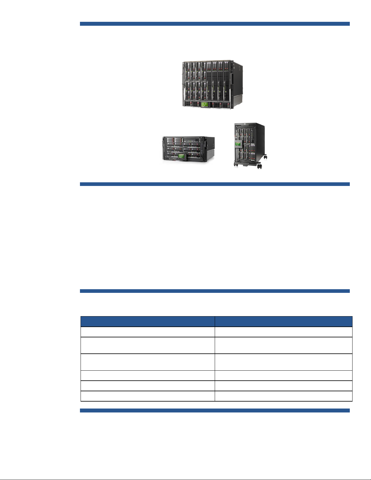
Figure 1: c-Class HP BladeSystem Enclosure Family
HP BladeSy stem c7000 enclosure
HP BladeSy stem c3000 enclosure
Both enclosures share common:
HP BladeSy stem c3000 Tower
• Half-height /full-height server blades
• Interconnect modules
• Mezzanine Host Bus Adapter (HBA) cards
• Storage blades
• Power Supplies (hot swappable and redundant)
• Fans (hot-swappable and redundant)
A comparison between the c3000 and c7000 enclosures is shown in Table 1.
Table 1: HP BladeSystem c-Class Enclosure Comparison
c3000 enclosure and tower enclosure c7000 enclosure
6U Height (rack) or tower 10U height
Horizontal blade orientation
Vertical blade orientation for tower
8 HH (half-height) Blades,
4 FH (full-height) Blades,6HH/1FH
4 Interconnect bays 8 Interconnect bays
6 Power Supplies @ up to 1200W each 6 Power Supplies @ up to 2250W each
6 Active Cool Fans 10 Active Cool Fans
Vertical blade orientation
16 HH (half-height) Blades,
8 FH (full-height) Blades
3
Page 4

Device and Interconnect Bays
The interconnect bays for each enclosure can support a variety of Pass-Thru modules and switch
technologies, including Ethernet, Fibre Channel, and InfiniBand. The enclosures support redundant
I/O fabrics and can yield up to a 94% reduction in cables compared to traditional rack-mounted
server configurations.
One of the major differences between the c3000 and c7000 is in the number of available
interconnect bays; the c3000 has 4 while the c7000 has 8. The four additional interconnect bays in
the c7000 offer additional I/O flexibility and the ability to use redundant interconnects to eliminate
single points of failure (SPOFs), which is extremely important to help protect mission-critical
applications in the data center. Using redundant interconnect modules in high availability HP
BladeSystem configurations will be described in later sections of this white paper.
Figure 2 shows a side-view of a c7000 enclosure and the major component connections.
Figure 2: HP BladeSystem c-Class Enclosure Side View
Fans
Half-height server blade
Switch
modules
Half-height server blade
Fans
Power supply modules
Fans
AC input moduleSignal midplane Power backplane
The c7000 enclosure, as with the c3000, enables easy connection of embedded server device ports
from the device bays to the interconnect bays.
The enclosure signal midplane transfers I/O signals (PCIe, Gigabit Ethernet, Fiber Channel) between
the server blades (half-height or full-height) and the appropriate interconnects, and has redundant
signal paths between servers and interconnect modules. Since the connections between the device
bays (in the front of the enclosure where the blade servers reside) and the interconnect bays (in the
back of the enclosure containing the interconnect modules) are hard-wired through the signal
midplane, the Mezzanine cards – host bus adapters (HBAs) used to connect the blade servers with an
interconnect module - must be matched to the appropriate type of interconnect module. For example,
a Fiber Channel Mezzanine card must be placed in the Mezzanine connector that connects to an
interconnect bay holding a Fiber Channel switch. For port mapping purposes, it does not matter in
which bay you install a server blade; Mezzanine connectors in the blade expansion slots always
connect to the same interconnect bays.
4
Page 5

To simplify the installation of the various Mezzanine cards and interconnect modules, the Onboard
Administrator, which manages the components within the enclosure, uses an “electronic keying”
process to detect any mismatch between the Mezzanine cards and the interconnect modules.
The power backplane provides 12V DC power to server blades, fans, and interconnects. Both the
signal midplane and separate power backplane in the c7000 enclosure have no active components,
thus improving reliability.
The AC input module providing power to the redundant power supply modules can be configured to
use a variety of different power delivery modes, depending on customer availability requirements and
cost constraints. The module can be configured to use either single-phase or three-phase AC for NonRedundant Power, Power Supply Redundant and AC Redundant power delivery modes. A detailed
description of these power modes and enclosure power configuration options is described in the
technology brief titled “Technologies in the HP BladeSystem c7000 Enclosure” available at
http://h20000.www2.hp.com/bc/docs/support/SupportManual/c00816246/c00816246.pdf. It
is recommended to use both Power Supply Redundant and AC Redundant power delivery modes to
achieve the highest levels of availability, if possible.
Figure 3 shows the interconnections between the device I/O from the server blades in the front of the
c3000 enclosure to the interconnect switch module (SWM) ports located at the rear of the enclosure
for data transfer. The color-coded symbols on the diagram are identical to the symbols used on the
physical enclosure and Onboard Administrator port mapping displays to identify the interconnect
bays (see figure 4). Each front device bay is connected through the signal backplane to each of the
rear interconnect bays. Interconnect bays 1 (for the c3000 / c7000) and 2 (for the c7000) are
dedicated to signals from the embedded NICs located on the server blade system board. The
remaining interconnect bays are available to accept signals from Mezzanine HBA cards mounted
directly on the server blades. The server blade Mezzanine card positions connect directly through the
signal mid-plane to the interconnect bays. The interconnect bays are designed to accept single-wide
or double-wide switch modules (SWMs) for interconnect bandwidth and form factor scalability.
HP Integrity BL860c and BL870c blade servers are full-height and provide connections for two 2-port
embedded NICs, also known as “LAN on Motherboard”, or LOM, and up to three 4-port Mezzanine
HBAs (labeled Mezz-1 – Mezz-3) as shown in figures 3 and 4. PCIe (PCI Express) connectivity from
the blade system board to the LOM and Mezzanine HBAs uses paired groups of full-duplex
communication “lanes”. A single-wide lane provides a 1x 500MB/s transfer rate, and a double-wide
or two lanes provide a 2x transfer rate of1Gb/s. Mezzanine cards are categorized into “types” that
describe their data transfer capabilities. Type I Mezzanine cards provide 1x transfer rate, while Type
II Mezzanine cards provide 1Gb/s through a single lane. Embedded LOM and host bus adapters
installed in Mezzanine card slot 1 support single-wide lane interconnects, while Mezzanine slots 2
and 3 support either single-wide or double-wide lane interconnects. Figures 3 and 5 show the PCIe
lane connections available to the LOM and Mezzanine cards on the blade server.
The Integrity BL860c is a single-wide server blade. The designation “N” in the diagram is used to
map single-wide server blade connections to the switch module bay ports. The BL870c is a doublewide server blade and follows a slightly different port mapping scheme in that:
• If a BL870c server blade is in device bays 1 and 2, the value of "N" is 2
• If a BL870c server blade is in device bays 3 and 4, the value of "N" is 4
Several points to note regarding the c3000 diagram are:
• All four LOM ports on each server blade use the same interconnect switch module bay SWM-1
• All four ports of Mezzanine card 1share the same interconnect switch module bay SWM-2
• Ports on Mezzanine cards 2 and 3 are divided between interconnect switch module bays SWM-3
and SWM-4
5
Page 6

Due to the limited number of available interconnect module slots in the c3000, it is not possible to
configure the enclosure for complete redundancy to eliminate a Mezzanine card and interconnect
module as a single point of failure between the server blade and connectivity to the outside system
infrastructure. This is an important point to consider when deploying mission-critical environments an
whether this configuration will meet defined availability requirements.
Figure 3: HP BladeSystem c-Class Enclosure Side View
PCIex4
PCIex4
PCIex8
PCIex4
PCIex8
Full-Height
Server Blade N
(N = 1…4)
2
NIC
1
4
NIC
3
2
1
4
3
2
1
2
1
4
3
2
1
Mezz-1
Mezz-2
Mezz-3
GbX1
GbX2
2x
2x
N N+8
N+4
N+12
N N+8
N+4 N+12
SWM-1 SWM-2
N N+8
N+4
N+12
N N+8
N+4
SWM-3 SWM-4
Blade Slot # N = 2,4 for Integrity BL870c
N+12
For visual reference, Figure 4 shows the c3000 enclosure rack and tower Interconnect bay numbering
scheme.
6
Page 7

Figure 4: HP BladeSystem c-3000 Enclosure Rack and Tower Interconnect Bay Numbering
Server blade signal Interconnect bay Interconnect bay label
NIC 1, 2, 3, 4 (embedded) 1 – Orange hexagon
Mezzanine 1 2 – Yellow square
Mezzanine 2 3 and 4 – Green circle
Mezzanine 3 3 and 4 – Blue diamond
Figure 5 shows the interconnections between the server blades and interconnect switch module
(SWM) ports for the c7000 enclosure, with a similar physical interconnect bay color-coding scheme
(see figure 6). The mapping of the Bl860c and BL870c blade connections to the switch module bay
ports is similar to the c3000 enclosure; however since the enclosure has 8 available device bays,
• if a BL870c server blade is in device bays 1 and 2, the value of "N" is 2
• if a BL870c server blade is in device bays 3 and 4, the value of "N" is 4
• If a BL870c server blade is in device bays 5 and 6, the value of "N" is 6
• If a BL870c server blade is in device bays 7 and 8, the value of "N" is 8
7
Page 8

Figure 5: HP BladeSystem c7000 Enclosure Interconnect Diagram
Full-Height
Server Blade N
(N = 1…8)
GbX1
PCIe x4
NIC
2
1
2x
2x
N N+8 N N+8
SWM-1 SWM-2
N
PCIe x4
PCIe x8
Mezz-1
Mezz-2
4
3
2
1
4
3
2
1
N
N+8
SWM-3 SWM-4
N+8
N
N
N+8
N+8
SWM-5 SWM-6
PCIe x4
PCIe x8
Mezz-3
NIC
2
1
4
3
2
1
GbX2
N
Blade Slot # N = 2, 4,6,8 for Integrity BL870c
N+8
N
SWM-7 SWM-8
N+8
Several points to note regarding the c7000 diagram are:
• The two LOM modules, each with a dedicated PCIe bus and two ports on each blade server, are
divided between interconnect switch module bays SWM-1and SWM-2 (although NIC ports 1 on
each LOM controller share SWM1 and NIC ports 2 share interconnect switch module SW2)
• Ports on Mezzanine cards 1, 2 and 3 are divided between interconnect switch module bays SWM-
3 thru SWM-8
With the additional interconnect module slots in the c7000, it is now possible to configure the
enclosure to eliminate both Mezzanine cards and interconnect modules as single points of failure
between the server blade and connectivity to the outside system infrastructure. Therefore, deploying
c7000 enclosures is a best practice recommendation for mission-critical environments.
For visual reference, Figure 6 shows the c7000 enclosure Interconnect bay numbering layout.
8
Page 9

Figure 6: HP BladeSystem c7000 Enclosure Interconnect Bay Numbering
Server blade signal Interconnect number Interconnect bay label
NIC 1 and NIC 3 ( embedded ) 1 – Orange hexagon
NIC 2 and NIC 4 ( embedded ) 2 – Orange hexagon
Mezzanine 1 3, 4 – Yellow square
Mezzanine 2 5, 6 and then 7, 8 – Green circle/Blue diamond
Mezzanine 3 7, 8 and then 5, 6 – Blue diamond/Green circle
HP BladeSystem Onboard Administrator
BladeSystem Onboard Administrator (OA) (figure 7) is located below the interconnect bays and
provides component management in c-Class enclosures by:
• Detecting component insertion and removal
• Identifying components and required connectivity
• Managing power and cooling
• Controlling components
Administrators access the BladeSystem OA in several ways:
• Remotely through the web browser graphical user interface (GUI)
• Scriptable command line interface (CLI)
• On-site through the built-in Insight Display diagnostic LCD panel on the front of the enclosure
• OA with KVM (Keyboard, Video, Mouse) module allows direct connection to the enclosure with a
keyboard, video monitor, mouse or KVM switch through a VGA port
When a component is inserted into a bay, the BladeSystem Onboard Administrator immediately
recognizes and identifies the component through presence signals on each bay. If a component is
removed from a bay, the BladeSystem Onboard Administrator deletes the information about that
component from its current configuration.
Each Onboard Administrator module has one Ethernet and one serial port that can be used to link
enclosures in a rack. Enclosure links are designed to support only c-Class enclosures in the same rack,
and both c3000 and c7000 enclosures can be linked and managed together. It is a best practice
9
Page 10

recommendation to verify that both Onboard Administrator modules have the same and latest
firmware revisions installed.
Figure 7: HP BladeSystem Onboard Administrator
HP Integrity Blade Servers
HP Integrity blade servers - the BL870c and BL860c - enable customers to run and consolidate
business and mission-critical applications in the flexible BladeSystem c-Class infrastructure, providing
superior virtualization, high availability, scalability, simplified management, and energy efficiency.
The full-height BL860c is a two-socket blade server that supports dual-core Intel Itanium 9100
processors, up to 48GB memory, four Gigabit Ethernet ports, support for 3 standard c-Class I/O
mezzanine cards, and up to two internal SFF (Small Form Factor) SAS (Serial Attached SCSI) hot-plug
disk drives. The BL860c is a low-cost platform suited for testing, development and production
application consolidation, especially in IT organizations using HP-UX operating environments.
The HP Integrity BL870c Server Blade is a four-socket, full-height double-width server blade that can
support Intel Itanium 9100 series dual-core processors with up to 96GB memory, four Gigabit
Ethernet ports, three standard c-Class I/O mezzanine cards, and up to four internal SFF SAS hot-plug
disk drives. The BL870c is an ideal platform for use as the database tier of multi-tiered enterprises
applications such as SAP, and Oracle Enterprise Applications, in addition to distributed computing
applications for industries such as retail distribution, communications and financial services.
Both the BL860c and BL870c blade servers support HP-UX 11i v2 and 11i v3, Serviceguard A.11.17
and later versions and can coexist with ProLiant server blades and StorageWorks storage blades
within the c-Class enclosure. Table 2 shows a feature comparison of the BL860c and BL870c.
10
Page 11

Table 2: HP Integrity Blade Comparison
Intel®Itanium
9100 Processors
BL860c BL870c
2 Sockets
1.66 GHz/18MB FSB667
Processor
Chipset hp zx2
1.42GHz/12MB FSB533
1.6GHz/12MB FSB533, single-core
Note: 9000 series processor (Montecito)
also supported
®
Intel®Itanium®9100 Processors
4 Sockets
1.6 GHz/24MB FSB533
1.6 GHz/18MB FSB533
1.42 GHz/12MB FSB533
PC2-4200 DDR-SDRAM (533 MHz)
Memory
HDD and
Controller
Networking 4 Integrated Gigabit NICs
Management Integrity iLO 2 Advanced Pack
OS Support HP-UX 11i v3 and v2; OpenVMS; Linux (Red Hat and SUSE); and Windows
Enclosure
Mezzanine
Support
12 Sockets
48GB max (using 4GB DIMMs)
2 SFF Hot-Plug SAS HDDs
HW RAID 1 support
8 Server Blades in c7000
4 Server Blades in c3000
3 mezzanine cards
Choices: 4Gb FC; IB; PCI-e pass-thru; 4port NIC expansion
PC2-4200 DDR-SDRAM (533 MHz)
24 Sockets
192GB max (using 8GB DIMMs)
4 SFF Hot-Plug SAS HDDs
HW RAID 1 support
4 Server Blades in c7000
2 Server Blades in c3000
3 mezzanine cards
Choices: 4Gb FC, IB, 4-port NIC
expansion
Eliminating Single Points of Failure in HP BladeSystem
Configurations
Designing a system architecture that eliminates all hardware-related single points of failure is the first
step in achieving high availability for business and mission-critical applications. While there are many
components of the HP BladeSystem that are redundant, it is still possible to configure HP BladeSystem
solutions that have single points of failure (SPOFs). It is up to the system architect to carefully design
HP BladeSystem solutions that will mitigate these SPOFs before using Serviceguard to achieve the
highest levels of availability. This section will describe where SPOFs can occur in HP BladeSystem
configurations and how to avoid them. Once these SPOFs have been addressed from a hardware-
11
Page 12

perspective, the next section of this white paper will describe how to incorporate Serviceguard into
the solution to maximize overall availability.
Redundant Hardware Configurations within Blade Enclosures
For data center applications, the HP BladeSystem c7000 enclosure includes the following redundant
components:
• Up to 6 power supplies
• Up to 10 Active Cool fan kits
• Up to 8 interconnect modules
• Redundant signal midplane paths
• Redundant enclosure management using Active / Standby Onboard Administrators (OAs)
HP Integrity Server Blade redundancy features include:
• Two dual-port Gigabit Ethernet embedded NICs (LOM)
• 3 Mezzanine I/O slots
• Up to two internal SFF (Small Form Factor) SAS (Serial Attached SCSI) hot-plug hard drives
(BL860c)
• Up to four internal SFF SAS hot-plug disk drives (BL870c)
The following sections describe how to utilize many of these redundancy features in HP BladeSystem
solution designs.
Redundant Enclosure Management
Redundant enclosure management is an optional feature of both the c3000 and c7000. Utilizing this
feature requires installing a second HP BladeSystem Onboard Administrator (OA) module in the
enclosure slot adjacent to the first OA to serve as a completely redundant controller in an activestandby mode. The redundancy logic of the OA module pair is based on a continuous heartbeat
between the two modules over a dedicated serial connection in the signal midplane. If the period
between heartbeats exceeds an internal timeout value set within the OA software, the standby module
automatically takes control of the enclosure and becomes the active BladeSystem Onboard
Administrator.
When two Onboard Administrator modules are installed in the enclosure, either module can be the
active module with the other becoming the standby module. Configuration data is constantly
replicated from the active Onboard Administrator module to the standby Onboard Administrator
module, regardless of the bay in which the active module currently resides. If two Onboard
Administrator modules of the same firmware revision are installed, the module on the left of the
enclosure will be the active OA. If two Onboard Administrator modules installed into the same
enclosure have different firmware versions, the automatic configuration synchronization feature is
disabled.
When the active Onboard Administrator module fails, the standby Onboard Administrator module
automatically becomes active. This occurs regardless of the position of the active Onboard
Administrator module. This automatic failover occurs only when the currently active module comes
completely offline and the standby module can no longer communicate with it. In all other cases, a
system administrator must initiate the failover by logging into the standby module and promoting it to
be the active Onboard Administrator. After the failed Onboard Administrator module is replaced (the
modules are hot-pluggable), it automatically becomes the standby module and receives the
12
Page 13

configuration information from the active module. It remains as the standby until either a system
administrator manually promotes it to the active module or the active module fails.
General HP BladeSystem I/O Redundancy Considerations
HP Integrity server blades I/O connectivity provides for:
• 2 LAN on Motherboard (LOM) modules (2 ports each @ 1Gb/s; 4 ports total)
• Support for up to 3 Mezzanine cards
With this hardware connectivity, it is possible to use a combination of LOM ports and Mezzanine
cards to provide redundancy for both network and storage connections to the server blade. HP
recommends configuring primary and alternate paths to use different Mezzanine cards and
interconnect modules to eliminate these components as potential SPOFs, if possible. However;
depending on the Mezzanine card configuration chosen based on customer availability requirements
and cost, it is acceptable to have both primary and alternate paths defined through one multi-port
Ethernet or Fibre Channel Mezzanine card.
Networking Connectivity
With the four internal Ethernet ports provided on Integrity server blades using two LOM NICs that
have independent hardware port controllers, it is possible to create a redundant networking
configuration that eliminates the blade networking ports as a SPOF. This is achieved by configuring
the LOM ports to avoid a potential port controller failure that could disable two ports by using ports 1
and 4 as the Serviceguard primary and standby connection for one network (e.g., site data LAN) and
ports 2 and 3 as the primary and standby connection for another network (e.g., Serviceguard
heartbeat). Using this configuration, Serviceguard local LAN failover would protect against either a
port controller or interconnect module failure. Note that it is also possible to use APA (Auto-Port
Aggregation) LAN_MONITOR mode to provide an active / standby network port configuration.
However; APA trunking or load balancing is not supported with Virtual Connect as Virtual Connect
does not provide pass-through of LACP (Link Aggregation Control Protocol) frames to host systems.
HP also recommends using an additional 4-port Ethernet Mezzanine card, if required, to provide
additional network connections based on application use requirements (e.g., VM host supporting
multiple VM networks).
Using redundant HP Virtual Connect (VC) Ethernet modules is another method to improve network
connection availability. VC Ethernet modules, when installed in a side-by-side bay pair configuration
in interconnect bays 1 and 2, run as a high availability pair. Redundancy daemons running on both
modules determine the active VC Manager (usually in bay 1) using internal heartbeats maintained
over multiple paths (signal midplane, Ethernet link, Onboard Administrator) and can automatically
switch to the other VC Ethernet module in the event of a loss of heartbeat. There are no specific
network requirements for using Serviceguard with Virtual Connect other than the recommendation to
eliminate a SPOF by using redundant VC Ethernet modules.
Virtual Connect also facilitates Ethernet link failover by allowing Virtual Connect networks to utilize
ports on multiple Virtual Connect modules in the same VC Domain. VC domains using Virtual Connect
Manager can span up to four enclosures; additional enclosures can be managed using Virtual
Connect Enterprise Manager. Depending on the configuration, a VC network will transparently shift
its upstream communication to a port on the same module or on a different module in the event of a
link failure. HP recommends using fully redundant interconnection of Virtual Connect Ethernet modules
so that, if a stacking cable is lost, Ethernet packets within the VC domain will be automatically rerouted to the uplink through the redundant path. This connection also preserves network connectivity if
an Ethernet interconnect module fails or is removed. Figure 8 shows an example of stacked Virtual
Connect Ethernet modules.
13
Page 14

Figure 8: Example of Stacked Virtual Connect Ethernet Modules
Fiber Channel SAN Connectivity
2-port Fiber Channel Mezzanine cards are available for connecting server blades to a SAN
infrastructure. HP recommends using two FC Mezzanine cards for redundancy to eliminate the
Mezzanine cards as a SPOF. When using Virtual Connect Fiber Channel modules, HP recommends
deploying the modules as side-by-side interconnect bay pairs for module redundancy with each Fiber
Channel port. Note that Virtual Connect Fiber Channel modules do not have any interdependencies
or mechanisms within the modules themselves to support VC-FC module failure failover as do Virtual
Connect Ethernet modules.
Multi-pathing for Fiber Channel links can be provided by using HP-UX 11i v3 native multi-pathing,
LVM PV (Physical Volume) Links or VERITAS DMP (Dynamic Multi-Pathing). Serviceguard monitoring
and failover triggered by a failed Fiber Channel link can be accomplished by using the EMS Disk
Monitor for LVM by configuring a package dependency on EMS disk monitor, or by using the VxVM
Volume Monitor that was available starting with Serviceguard A.11.18. Information on using EMS
Monitors is available at http://www.docs.hp.com/en/B5735-90001/ch01s04.html and rules for
using the HA Disk Monitor with Serviceguard is available at http://www.docs.hp.com/en/B5736-
90074/ch02s02.html . The VxVM Volume Monitor is documented in the Managing Serviceguard
Manual, which is available at http://docs.hp.com/en/B3936-90140/B3936-90140.pdf.
HP Virtual Connect (VC) High Availability Server Profile Configurations
Instead of having to physically wire LAN and SAN connections to specific blade servers, HP Virtual
Connect (VC) server profiles provide the ability to virtually “wire” individual LAN and Fibre Channel
ports to specific networks and SANs by associating multiple network ports from one or more server
blades with one or more external output ports on a VC Ethernet card. From a Serviceguardperspective, if both the primary and standby LANs for a server blade shared the same output port on
the same Virtual Connect module, there would only be protection against a failure of the network port
on the Mezzanine card. A failure of the Virtual Connect module or the external switch connected to
the output port on that module would still be a SPOF.
14
Page 15

An improvement of this configuration would be to ensure the primary and standby LANs pass through
different VC modules, with the output ports on the VC modules connected to separate Ethernet
switches that are bridged together. This configuration would protect against the failure of a LOM port
controller, the network ports on the Mezzanine card, a VC module, a switch or cabling, and would
eliminate many more possible failure points. An example of such a configuration, using LOM ports 1
and 4 routed to different VC modules, is described in the next section.
The following is one example of using HP Virtual Connect to create a server profile for a BL860c
server blade to minimize SPOFs for its network and Fiber Channel connections. Note this is one
example, and many other acceptable HA configurations are possible depending on what Mezzanine
cards and interconnect modules are available for a server blade to utilize.
Figure 9 shows an HP BladeSystem Onboard Administrator window with information on a BL860c
server bladed installed in device bay 7.
Figure 9: Onboard Administrator Window showing BL860c information for Device Bay 7
LOM and
mezzanine
card
information
In this example, the BL860c has 4 embedded LOM NIC ports (ports 1 and 2 sharing one PCIe bus
and ports 3 and 4 sharing another PCIe bus), an iLO (Integrated Lights-Out) port, a 4Gb Fiber
Channel Mezzanine card in Mezzanine Slot 1 and a Quad Port 1Gb NIC Mezzanine Card in
Mezzanine Slot 2. Figure 10 shows the Port Mapping view for this server blade in Device Bay 7.
15
Page 16

Figure 10: Onboard Administrator Window showing Device Bay 7 Port Mapping
From the Port Mapping view, the embedded network ports, FC HBA ports from Mezzanine Slot 1 and
Ethernet ports from Mezzanine Slot 2 are shown mapped to their respective interconnect bay ports.
Note in this example configuration, ports 3 and 4 of the Quad-Port Mezzanine HBA are not mapped
because there are no interconnect modules in enclosure interconnect bays 7 and 8. Although these
ports are unavailable, the LOM ports on the blade server provide network redundancy, while at least
two ports of the Quad-Port Mezzanine card can provide additional network connectivity.
To utilize the redundant components available for the server blade in this configuration example, a
Virtual Connect server profile has been created as shown in figure 11. The server profile has been
configured to use LOM port 1 for the primary site LAN and LOM port 4 for the private Serviceguard
heartbeat LAN, with are assigned to interconnect bays 1 and 2, respectively. Note that LOM ports 2
and 3 were not used in this case because the standby site and secondary heartbeat LAN connections
have been configured to use the Ethernet ports on the Mezzanine Card Slot 2, which are assigned to
interconnect bays 5 and 6. If no additional Ethernet Mezzanine cards were available, all 4 internal
ports could have been used to achieve a redundant network configuration by using ports 1 and 4 as
the primary/standby pair for the site network and ports 2 and 3 as primary/standby pair for the
Serviceguard heartbeat network. This configuration now provides Ethernet hardware redundancy for
both the site and Serviceguard heartbeat LANs. In the event of either a LOM, Ethernet Mezzanine
card, or interconnect module failure, Serviceguard can recover from the failure by performing a local
LAN failover.
Since this configuration only has one 2-port Fiber Channel Mezzanine HBA installed in Mezzanine
Slot 1, it is only possible to configure the server profile to use each port assigned to interconnect bays
3 and 4. Although a 2ndFiber Channel Mezzanine card is not available, the ports of the one Fiber
Channel Mezzanine card are using separate interconnect modules, thus eliminating the interconnect
modules as a potential SPOF. However; for the highest level of availability, it is a recommended best
practice to use two Fiber Channel Mezzanine cards for compete redundancy.
16
Page 17

Figure 11: Server Profile for BL860c installed in Device Bay 7
Primary site
LAN and private
heartbeat LAN
assigned
to Interconnect
Bays 1 & 2
Standby site
LAN and
private
heartbeat LAN
assigned
to Interconnect
Bays 5 & 6
Fiber Channel
Ports 1 and 2
assigned
to Interconnect
Bays 3 & 4
In summary, this example uses the following Virtual Connect server profile configuration to minimize
SPOFs with the components that were available to this BL860c server blade:
• LAN on Motherboard (LOM):
– Port1: Site LAN
– Port 2: (unassigned)
– Port 3: (unassigned)
– Port 4: Serviceguard Heartbeat LAN
• Mezzanine Card 1 (Fiber Channel HBA)
– Port 1: SAN (primary)
– Port 2: SAN (alternate)
• Mezzanine Card 2 (Ethernet HBA):
– Port 5: Site LAN (standby)
– Port 6: Serviceguard Heartbeat LAN (secondary)
• Mezzanine Card 3 (not installed – recommend using a 2ndFibre Channel HBA for redundancy)
Using Serviceguard in HP BladeSystem Configurations
With the existing high availability features of the HP BladeSystem, adding Serviceguard for HP-UX on
Integrity blades builds upon that foundation to provide improved availability for mission-critical
applications. The complete Serviceguard Solution portfolio, including the Serviceguard Storage
Management Suite, SGeRAC, SGeSAP, Enterprise Cluster Master Toolkit and all Serviceguard
17
Page 18

Disaster Recovery solutions (i.e., Extended Distance Serviceguard clusters, Metrocluster,
Continentalclusters) are fully supported with the HP BladeSystem BL860c (A and B versions) and
BL870c Integrity server blades using the following HP-UX operating systems and Serviceguard
versions:
• HP-UX 11i v2 September 2006 (or later) with Serviceguard A.11.17 and SGeRAC A.11.17 (or
later)
• HP-UX 11i v3 September 2007 (or later) with Serviceguard A.11.18 and SGeRAC A.11.18 (or
later)
The following Mezzanine host bus adapters (HBAs) for the BL860c / BL870c Itanium server blades
supported with Serviceguard at the time of this white paper’s publication. Please contact your local
HP Sales Representative for a list of all currently supported HBAs with Serviceguard.
• Ethernet:
– HP BLc NC360m 2-Port Gigabit Ethernet adapter (P/N 445978-B21)
– HP BLc NC364m 4-port Gigabit Ethernet adapter (P/N 447883-B21)
• Fibre Channel:
– HP BLc QLogic QMH2462 2-port 4Gb FC HBA (P/N 403619-B21)
– HP BLc Emulex LPe1105 2-port 4Gb FC HBA (P/N 403621-B21)
– HP BLc QLogic QMH2562 2-port 8Gb FC HBA (P/N 451871-B21)
– HP BLc Emulex LPe1205 2-port 8Gb FC HBA (P/N 456972-B21)
• SAS (Serial Attached SCSI):
– HP Smart Array P700m/512 Controller (P/N 508226-B21)
• InfiniBand:
– HP BLc 4X DDR InfiniBand HBA (P/N 410533-B21)
– HP BLc 4X DDR Dual Port InfiniBand HBA (P/N 448262-B21)
The following interconnect modules for the BL860c / BL870c Itanium server blades and c-Class
enclosures are currently supported with Serviceguard:
• Ethernet Interconnects:
– HP BLc 1Gb Ethernet Pass-thru Module (P/N 406740-B21)
– HP BLc GbE2c Ethernet Blade Switch (P/N 410917-B21)
– Cisco Catalyst Blade Switch 3020 (P/N 410916-B21)
– Cisco Catalyst Blade Switch 3120G (P/N 451438-B21)
– Cisco Catalyst Blade Switch 3120X (P/N 451439-B21)
– HP BLc 1/10Gb-F Virtual Connect Ethernet Module (P/N 447047-B21)
– HP BLc 1/10Gb Virtual Connect Ethernet Module (P/N 399593-B22)
– HP ProCurve 6120XG Ethernet Blade Switch (P/N 516733-B21)
– HP ProCurve 6120G/XG Ethernet Blade Switch (P/N 498358-B21)
– HP 10GbE Ethernet Pass-thru Module (P/N 538113-B21 )
– HP 1:10Gb Ethernet BL-c Switch (P/N 438031-B21)
18
• Fibre Channel Interconnects:
Page 19

– HP BLc 4Gb Fibre Channel Pass-thru Module (P/N 403626-B21)
– Brocade 4/12 SAN Switch (P/N AE370A - Note P/N AE373A to upgrade the AE370 12 port
switch to 24 ports is also supported)
– Brocade 4/24 SAN Switch for c-Class BladeSystem (P/N AE372A)
– Cisco MDS 9124e 12-port Fabric Switch (P/N AG641A)
– Cisco MDS 9124e 24-port Fabric Switch (P/N AG642A)
– HP B-series 8/12c SAN Switch (P/N AJ820A)
– HP B-series 8/24c SAN Switch (P/N AJ821A or AJ822A)
– HP BLc 4Gb Virtual Connect Fibre Channel Module (P/N 409513-B21 or 409513-B22)
– HP Virtual Connect 8Gb 24-Port Fibre Channel Module (P/N 466482-B21)
– HP Virtual Connect 8Gb 20-Port Fibre Channel Module (P/N 572018-B21)
• SAS Interconnects:
– HP 3Gb SAS BL Switch (P/Ns AJ864A or AJ865A; note this interconnect module is supported
only with the P700m SAS Controller mezzanine HBA)
• InfiniBand Interconnects:
– HP BLc 4X DDR InfiniBand Switch Module (P/N 410398-B21)
– HP BLc 4X DDR InfiniBand Gen 2 Switch Module (P/N 489183-B21)
Serviceguard Clustering within a Single Blade Enclosure
With the ability of HP BladeSystem enclosures to contain multiple HP Integrity server blades, it is
possible to run a Serviceguard cluster completely self-contained within an enclosure. Figure 12 shows
an example of this type of configuration, also known as a “cluster in a box”.
Figure 12: Example of a Serviceguard “cluster in a box” Configuration using a c7000 Enclosure
HP S ystems Insight Manager (SIM)
Central Management Server (CMS)
Redundant
Network
Links
Serviceguard
cluster
c7000 BladeSystem
Quorum Service
(Linux OS)
Enclosure
Redundant
Fibre
Channel
Links
EVA Disk Array
19
Page 20

In this example, a 4-node Serviceguard cluster is configured in a single c7000 enclosure, with an
EVA disk array used for shared storage between the cluster nodes. An HP Systems Insight Manager
Central Management Server is also shown, which provides overall management of the systems
environment from outside of the Serviceguard cluster. While this example shows 4 integrity server
blades used as cluster nodes, it is also possible to use HP Integrity Virtual Machines as Serviceguard
nodes. HP Virtual Connect (not shown in this figure) can be configured to provide a private cluster
heartbeat network within the enclosure for the cluster nodes without requiring any external wiring or
switches. A quorum service, running on a Linux OS in this example, provides quorum for the 4-node
cluster. Note it is supported to use a cluster lock disk or lock LUN for a 2, 3 or 4-node configuration
within a blade enclosure; however it is recommended to use a quorum service for clusters having 3 or
mode nodes.
While this configuration is supported, it is not recommended because the blade enclosure is
considered a single point of failure (SPOF) that could potentially fail and bring down the entire
cluster. However; one recommended best practice shown in this diagram is the placement of the CMS
on a system external to the blade enclosure so that it can remain functional for managing other
systems in the environment in the event the blade enclosure is unavailable due to some firmware
update operations requiring the entire enclosure to be down or a power failure of the enclosure.
Advantages and Limitations
This configuration has the following advantages and limitations:
Advantages:
• Provides a completely self-contained Serviceguard cluster within a single enclosure
• Internal cluster heartbeat network can be configured using Virtual Connect to eliminate additional
network cabling and switches
• Provides consistent management of server profiles using Virtual Connect with all cluster nodes within
the blade enclosure
Limitations:
• The blade enclosure is a single point of failure that can cause the entire cluster to go down
• There are no nodes external to the cluster to failover workloads in the event of planned enclosure
maintenance (e.g., Virtual Connect and / or Onboard Administrator firmware upgrades that
require all blades in the enclosures to be shutdown)
Clustering across Multiple Blade Enclosures or non-Blade Servers
One architecture design for improving a “cluster in a box” configuration is to split the Serviceguard
cluster nodes between multiple blade enclosures or other external Serviceguard cluster nodes to avoid
having a single enclosure as a single point of failure (SPOF). Figure 13 is an example of this
architecture with a Serviceguard cluster spanning multiple c7000 blade enclosures.
20
Page 21

Figure 13: Cluster Example Spanning Multiple c7000 Enclosures
HP Systems Insight Manager (SIM)
Central Management Server (CMS)
VC Stacking Link
Serviceguard
c7000 BladeSystem
Enclosure
EVA
Disk Array
Quorum Service ( HP-UX OS)
LAN
cluster
SAN
c7000 BladeSystem
Enclosure
In this example, a single 8-node Serviceguard cluster spans two c7000 enclosures, with 4 nodes in
each enclosure attached to shared storage provided by an EVA disk array. A Virtual Connect
stacking link is used between the enclosures to provide a private cluster heartbeat network between
the enclosures. A Systems Insight Manager Central Management Server is used to provide overall
management of the systems environment; however this server is not part of the Serviceguard cluster.
Note that it is permissible to mix server blades with other external physical or virtual (i.e., nPar, vPar,
HP Integrity Virtual Machine) Serviceguard nodes in this configuration. However; no enclosure or
complex can contain more than half of the cluster nodes (e.g., server blades, nPars), and requires an
external quorum server to maintain cluster quorum in the event of a blade enclosure failure. A quorum
service, running on a small HP-UX system in this example, is located outside of the blade enclosures to
serve as a tie-breaker in case of an enclosure failure to allow the remaining 50% of the surviving
cluster nodes to successfully form a new cluster. Additional information on Serviceguard cluster
quorum requirements is available in the white paper titled “HP Serviceguard Cluster Configuration for
HP-UX 11i or Linux Partitioned Systems” posted at
http://docs.hp.com/en/6033/HPServiceguardClusterConfig_WP.pdf.
Advantages and Other Considerations
Having a Serviceguard cluster span multiple c7000 enclosures or other non-blade cluster nodes has
many advantages over a “cluster in a box” configuration, and few limitations:
21
Page 22

Advantages:
• Protects against a complete blade enclosure failure
• Provides the flexibility of moving workloads to another enclosure for planned maintenance (e.g.,
Virtual Connect and / or Onboard Administrator firmware upgrades that require all blades in the
enclosures to be shutdown)
• Internal cluster heartbeat network can be configured using Virtual Connect stacking links connected
between the Virtual Connect interconnect modules and different enclosures to eliminate additional
network cabling and switches
• Provides consistent management of server profiles using Virtual Connect or Virtual Connect
Enterprise Manager when all cluster nodes are in blade enclosures
Other Considerations:
• Additional cost for a 2ndblade enclosure or other non-blade cluster nodes
• A quorum server outside of the enclosure is required for this configuration
• Configurations must have exactly half of the cluster nodes in an enclosure, complex (e.g., nPar,
vPar) and/or other combination of external servers
Additional Considerations for using Serviceguard with the
HP BladeSystem
The following is a list of the major recommendations covered in this white paper and additional points
to consider when configuring HP BladeSystem solutions with Serviceguard to maximize application
availability:
HP BladeSystem Enclosures and Internal Storage:
• Ensure the firmware versions on all blade servers, Mezzanine cards, interconnect cards and
Onboard Administrators are consistent and current within an enclosure participating in the
Serviceguard cluster and VC domain to ensure reliable application failover
• Since some Virtual Connect and Onboard Administrator firmware upgrades require all blades
within the enclosure to be down, it is recommended to configure Serviceguard clusters between
enclosures and failover applications before performing enclosure firmware upgrades or other
planned enclosure maintenance
• The SB40c Storage Blade is not supported for use as Serviceguard shared storage
• The Internal disks in a server blade cannot be used for Serviceguard shared storage; however they
can be used as boot/root disks with either MirrorDisk/UX or the embedded RAID controller for data
redundancy
Ethernet Connectivity:
22
• The 10/100 Base-T iLO port on the c-Class BladeSystem Enclosure cannot be used in the
Serviceguard cluster configuration or with Serviceguard relocatable IP addresses
• LAN on Motherboard (LOM) ports are supported with Serviceguard; however for Serviceguard to
reliably detect a LOM port failure on BL860c “A” version and BL870c blades, the Serviceguard
cluster configuration must have the NETWORK_FAILURE_DETECTION parameter set to
INONLY_OR_INOUT (the default for this parameter is INOUT)
Page 23

– For more information on setting this parameter, see the Serviceguard Network Manager Inbound
Failure Detection white paper at: http://docs.hp.com/en/5568/serviceguard.network.manager.pdf
– This issue also affects HP-UX APA (Auto-Port Aggregation) link aggregates and APA failover
groups (LAN_MONITOR mode)
– This hardware issue and a list of available solutions is documented in the HP Support
Communication Customer Advisory at:
http://h20000.www2.hp.com/bizsupport/TechSupport/Document.jsp?objectID=c01814615&lang=en&cc
=us&taskId=101&prodSeriesId=3676868&prodTypeId=3709945
• Recommend using network ports from different LOM port controllers for redundant active/standby
Serviceguard site and heartbeat network configurations
Fibre Channel Connectivity:
• Each server blade must have at least 1 Mezzanine card for Fiber Channel connectivity
– If a server blade has 2 or more Fiber Channel Mezzanine cards, it is recommended that the
primary and alternate Fiber Channel paths use different Mezzanine cards to prevent a
Mezzanine card from being a single point of failure
Virtual Connect:
• Uplinks between Virtual Connect modules can be used for private cluster heartbeat networks
between blade enclosures (note stacking links between adjacent VC Ethernet modules is internal)
– Note when using dedicated internal cluster heartbeat networks, it can be difficult to test cluster
failover due to a loss of heartbeat as there is no physical LAN cable available to disconnect
Flex-10:
• The HP NC532m Dual Port 10GbE BL-c Adapter is supported with HP-UX and Serviceguard
• Can use the 1Gb Ethernet Mezzanine or LOM with the HP BLc Virtual Connect Flex-10 10Gb
Ethernet interconnect module (figure 14) with server blades running either HP-UX or Windows
The Flex-10 module will only operate as a 1Gb, non-Flex-10 module for HP-UX. While it cannot take
advantage of some Flex-10 features; it can be used at 1Gb and is supported with HP-UX and
Serviceguard.
Figure 14: HP BLc Virtual Connect Flex-10 10Gb Ethernet Interconnect Module
23
Page 24

InfiniBand:
• The HP BLc 4X DDR InfiniBand Mezzanine card, which requires the HP BLc 4X DDR IB Switch
Module (figure 15), is supported with Serviceguard
Figure 15: HP BLc 4X DDR InfiniBand Mezzanine cardand HP BLc 4X DDR IB Switch Module
• Considerations for InfiniBand use:
– Few applications use native InfiniBand protocol; thus requiring the use of IPoverIB protocol (e.g.,
Oracle RAC 10g and 11g currently support only IPoverIB), which dramatically increases CPU
overhead
– If VERITAS CVM or CFS is used, InfiniBand must not be configured as the Serviceguard cluster
heartbeat
– Using InfiniBand limits the ability to have high availability configurations for the Fibre Channel
and Ethernet mezzanine card as the IB interconnect module physically requires two interconnect
bay slots
Serviceguard Solutions Portfolio:
• The Serviceguard Storage Management Suite, SGeRAC, SGeSAP, and Enterprise Cluster Master
Toolkit can be used with HP BladeSystem configurations without any constraints or special
considerations
– Follow published manuals, release notes and white papers for suggested best practice
configurations
• HP BladeSystems are supported with all Serviceguard Disaster Recovery solutions (i.e., Extended
Distance Serviceguard clusters, Metrocluster, Continentalclusters)
Other Areas to Improve HP BladeSystem Solution Availability:
• Consider adding high availability to the Central Management Server. See the white paper titled
“Using HP Insight Software from a Highly Available Central Management Server with Microsoft
Cluster Service” posted at http://h20195.www2.hp.com/V2/GetPDF.aspx/c01956953.pdf for
more information.
• Also consider configuring the quorum service as a high availability Serviceguard cluster, which is
described in the HP Quorum Server documentation posted at
http://docs.hp.com/en/ha.html#Quorum%20Server
24
Page 25

Conclusion
The HP BladeSystem has many redundant features within its design to make it highly available.
Serviceguard for HP-UX on Integrity blades builds upon the HA features of the HP BladeSystem and
improves availability for mission-critical applications by fully utilizing its robust feature set that can:
• Detect hardware and software failures, and automatically moving critical applications to another
cluster node to minimize application downtime
• Integrate with HP’s partitioning solutions to provide protection for system configurations that best
meet customer’s needs
• Deliver application-targeted availability through the use of Serviceguard extensions for Oracle RAC
and SAP, Storage Management, Toolkits and the Developers Toolbox
• Provide a variety of disaster recovery options within the Serviceguard solutions portfolio
There are several key points to consider when implementing Serviceguard with HP BladeSystem
configurations to architect a solution that will maximize high availability:
• Configure blade components (e.g., LAN on motherboard, mezzanine HBAs and interconnect
modules) with redundancy in-mind within blade enclosures to avoid SPOFs (note many
configurations are possible)
• Consider potential cluster partitioning issues when configuring Serviceguard clusters that span
multiple enclosures or use external server nodes
• Consider the complete systems environment and look for other areas to improve overall availability
(e.g., CMS & quorum service clustering)
While the focus of this white paper was on HP Integrity server blades and Serviceguard solutions,
please note that the HP BladeSystem supports both HP Integrity and ProLiant server blades. Integrated
solutions for protecting HP BladeSystem continuity of services are also available for both server
platforms using virtual logical servers with Virtual Connect and Virtual Connect Enterprise Manager,
which are part of the Insight Dynamics advanced infrastructure lifecycle management software.
Additional protection is available for each of these platforms, as listed below:
HP Integrity:
• Mission critical “Application-aware” availability and disaster recovery is provided using the
Serviceguard family of products
• Movement of server profiles is available using HP Insight Dynamics - VSE for HP Integrity servers
HP ProLiant:
• Availability and disaster recovery can be provided using logical server profile recovery with Insight
Dynamics recovery management and HP Virtual Connect Enterprise Manager integrated with HP
Insight Dynamics suite for ProLiant servers
Please see the HP Insight Dynamics Protect Continuity of Services web page at
http://h18004.www1.hp.com/products/solutions/insightdynamics/protect.html for details on these
solutions.
25
Page 26

For More Information
To read more, see:
• HP BladeSystem: http://www.hp.com/go/bladesystem
• HP Serviceguard Solutions: http://www.hp.com/go/serviceguardsolutions
• HP Insight Dynamics: http://www.hp.com/go/insightdynamics
• HP Insight Dynamics – VSE for Integrity servers: http://www.hp.com/go/vse
Call to Action
HP welcomes your input. Please give us comments about this white paper, or suggestions for LVM or
related documentation, through our technical documentation feedback website:
http://docs.hp.com/en/feedback.html
© Copyright 2010 Hewlett-Packard Development Company, L.P. The information contained herein is subject to
change without notice. The only warranties for HP products and services are set forth in the express warranty
statements accompanying such products and services. Nothing herein should be construed as constituting an
additional warranty. HP shall not be liable for technical or editorial errors or omissions contained herein.
Trademark acknowledgments, if needed.
HP Publication Number 5697-0470, May 2010
Share with colleagues
 Loading...