

Page 1
MAINT ENANC E
& SERVICE GUIDE
ADDENDUM
Compaq Armada 1500
Family of Personal Computers
Page 2

. . . . . . . . . . . . . . . . . . . . . . . . . . . . . . . . . . . . . .
Notice
The information in this guide is subject to change without notice.
COMPAQ COMPUTER CORPORATION SHALL NOT BE LIABLE FOR TECHNICAL OR
EDITORIAL ERRORS OR OMISSIONS CONTAINED HEREIN; NOR FOR INCIDENTAL
OR CONSEQUENTIAL DAMAGES RESULTING FROM THE FURNISHING,
PERFORMANCE, OR USE OF THIS MATERIAL.
This guide contains information protected by copyright. No part of this guide may be
photocopied or reproduced in any form without prior written consent from Compaq
Computer Corporation.
1998 Compaq Computer Corporation.
All rights reserved. Printed in the U.S.A.
Compaq, LTE, Contura, ProLinea, QuickLock, QuickBlank are
registered in the U. S. Patent and Trademark Office. Armada is a trademark of Compaq
Computer Corporation.
Contura is registered in the Philippines Patent Office.
Microsoft, MS-DOS, and Windows are registered trademarks of Microsoft Corporation.
Windows 95 is a trademark of Microsoft Corporation.
The software described in this guide is furnished under a license agreement or
nondisclosure agreement. The software may be used or copied only in accordance with the
terms of the agreement. Product names mentioned herein may be trademarks and/or
registered trademarks of their respective companies.
Maintenance and Service Guide Addendum
Compaq Armada 1500 Family of Personal Computers
First Edition (January 1998)
Spare Part Number 255011-001
Document Part Number 255318-001
Compaq Computer Corporation
Page 3

. . . . . . . . . . . . . . . . . . . . . . . . . . . . . . . . . . . .
Addendum to Compaq Armada 1500
Maintenance and Service Guide
Computer Product Description
1.1 Models and Features
The following information describes new models and features of the Compaq Armada
1500 Family of Personal Computers. Selected models include Pentium processors
with MMX technology, faster internal modem, larger hard drive, faster internal CDROM drive, and mechanical enhancements to the base enclosure. A list of standard
features and supported options are provided in Chapter 1 of the Maintenance and
Service Guide, Compaq Armada 1500 Family of Personal Computers. The following
computer models are available:
Compaq Armada 1500 Family Models
Pentium
Model
1530D 133-MHz 12.1 STN 1.4-GB 16/80 MB 256-Kbyte 10X BRX1
1530DM 133-MHz 12.1 STN 1.4-GB 16/80 MB 256-Kbyte 10X 33.6 BRX2
1535DM 133-MHz 12.1 STN 1.4-GB 16/80 MB 256-Kbyte 12X 33.6 BRX3
1540D 150-MHz 12.1 TFT 2.1-GB 16/80 MB 256-Kbyte 20X BRX5
1540DM 150-MHz 12.1 TFT 2.1-GB 16/80 MB 256-Kbyte 20X 33.6 BRX6
1545DM 150-MHz 12.1 TFT 2.1-GB 16/80 MB 256-Kbyte 20X 56 BT61
1560 166-MHz 12.1 STN 2.1-GB 16/80 MB 256-Kbyte BT51
1560D 166-MHz 12.1 STN 2.1-GB 16/80 MB 256-Kbyte 20X BT52
1560DM 166-MHz 12.1 STN 2.1-GB 16/80 MB 256-Kbyte 20X 56 BT53
1580DT 150-MHz 12.1 TFT 2.1-GB 16/80 MB 256-Kbyte 10X BM58
1580DMT150-MHz 12.1 TFT 2.1-GB 16/80 MB 256-Kbyte 10X 33.6 BM59
1585DMT150-MHz 12.1 TFT 2.1-GB 16/80 MB 256-Kbyte 12X 33.6 BRX4
1590DT 166-MHz 12.1 TFT 2.1-GB 16/80 MB 256-Kbyte 20X BRX7
1590DMT166-MHz 12.1 TFT 2.1-GB 16/80 MB 256-Kbyte 20X 33.6 BRX8
1592DT 233-MHz MMX 12.1 TFT 3.2-GB 32/96 MB 512-Kbyte 20X BT54
1592DMT233-MHz MMX 12.1 TFT 3.2-GB 32/96 MB 512-Kbyte 20X 56 BT55
Processor Display
Hard
Drive
Memory
Std / Max
Level 2
Cache
CD-
ROM
Modem
( Kbps )
Serial
Configuration
Addendum 255318-001 to Guide 284820-001 1
Page 4

. . . . . . . . . . . . . . . . . . . . . . . . . . . . . . . . . . .
Addendum to Compaq Armada 1500
Maintenance and Service Guide
1.2 Features
The following features are provided on selected models:
EDO Dynamic Random Access Memory (DRAM) system memory: 16-MB expandable to 80-
MB, or 32-MB expandable to 96-MB
1.44-GB, 2.1-GB or 3.2-GB hard drive
11.3-inch Super Twisted Neumatic (STN) or 12.1-inch Thin Film Transistors (TFT) SVGA
display
33.6Kbps integrated modem or 56Kbps internal controllerless modem. (Both are standard on
selected models and available as an option on other models.)
Internal CD-ROM Drive standard on selected models and available as an option on other
models
Universal Serial Bus (USB) connector standard on selected models
2-MB video memory
256-Kbyte L2 Cache memory, or 512-Kbyte L2 Cache memory
Two standard device slots that will accommodate two types I and II and one type III PC
Cards, PCMCIA and Bus cards; Compaq Telephony modem in the top slot and ZoomedVideo in the bottom slot
The following features are provided on all models:
Supports Lithium Ion (Li-ion) and Nickel Metal Hydride (NiMH) modular battery packs
SoundBlaster-compatible audio controller with internal stereo speakers and internal
microphone
Full-size 101 key compatible keyboard including 12 function keys, 8 cursor control keys,
inverted-T cursor control keys and embedded numeric keypad
Four user-programmable keys
Touchpad pointing device
Operates from an internal battery pack, plus an optional battery pack in the Dualbay, or
integrated AC power that is compatible with domestic and international power sources
Power management and security features
2 Addendum 255318-001 to Guide 284820-001
Page 5

. . . . . . . . . . . . . . . . . . . . . . . . . . . . . . . . . . . .
Addendum to Compaq Armada 1500
Maintenance and Service Guide
Infrared interface for wireless communications with other IrDA-compliant devices at data
rates up to 4 MB/sec
176 pin expansion connector provides the interface to the Convenience Base options
Rear-panel ports provide connections for parallel and serial, external monitor,
keyboard/mouse and IrDA compliant infrared devices
1.3 Software Fulfillment
Replacement software may be ordered directly from Compaq Computer Corporation. Both the
model and the serial number of the computer are needed to identify the specific software
available.
Addendum 255318-001 to Guide 284820-001 3
Page 6
. . . . . . . . . . . . . . . . . . . . . . . . . . . . . . . . . . .
Addendum to Compaq Armada 1500
Maintenance and Service Guide
1.4 External Computer Components
The following information provides new mechanical changes to the models, which are different
from earlier models
Universal Serial Bus
A Universal Serial Bus (USB) connector has been added to select models on the left side of the
computer. The connector provides an interface for USB peripheral devices.
On models without the USB connector, a plastic insert covers the connector space. The plastic
USB cover is included in spare part 254981-001, the miscellaneous spare parts kit. The kit also
ships with such items as replacement clutch covers, rubber feet, battery spacer door, etc. (See
Chapter 4 in the Maintenance and Service Guide for miscellaneous spare parts.)
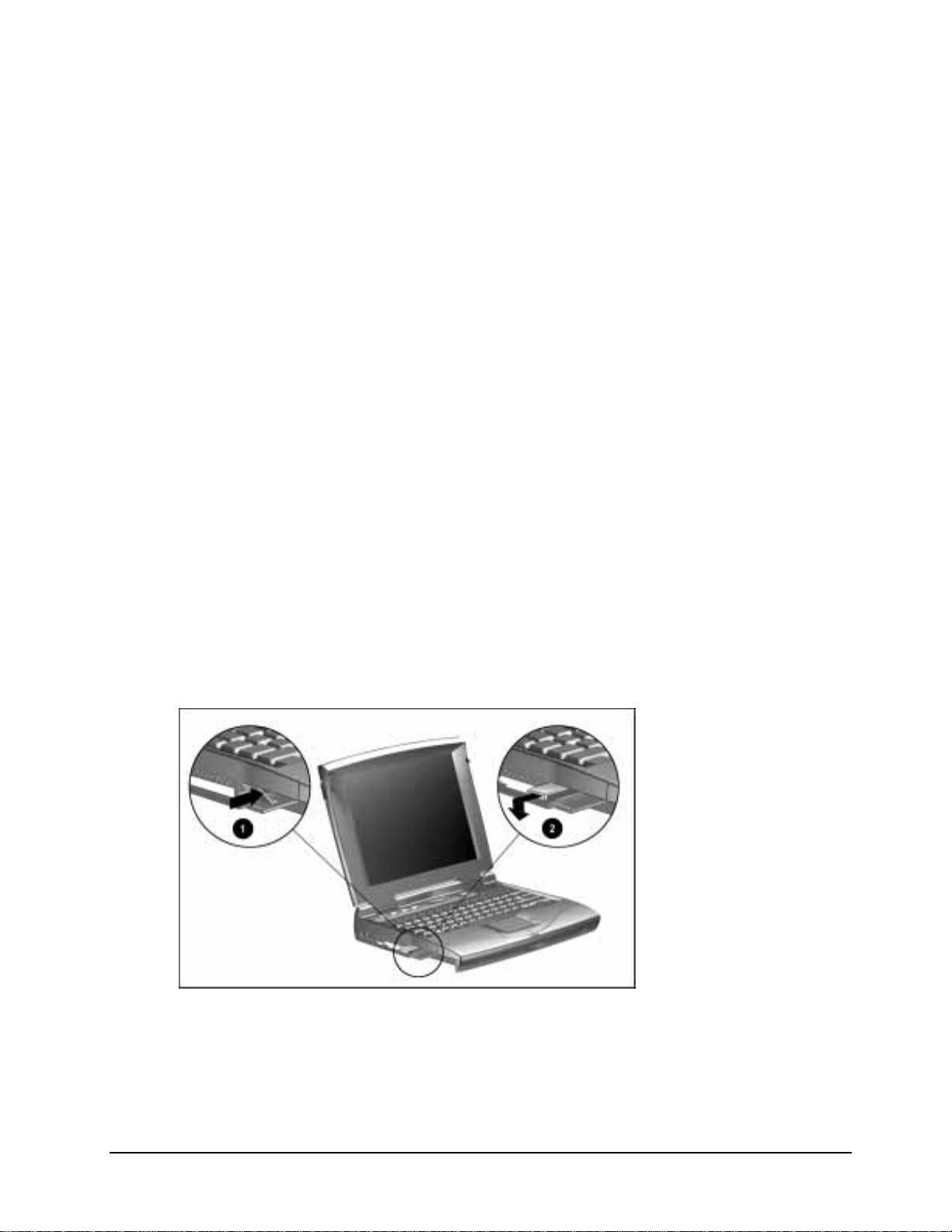
Battery Spacer Door
IMPORTANT: The Battery Spacer Door, which is a component of the Dualbay compartment, has
been modified.
The new battery spacer door pushes 1pushes inward with a single motion, as compared to the
previous version 2 which pulled out and pushed inward (
Figure 1-1).
NOTE: The Battery Spacer Door is included in the miscellaneous spare parts kit (spare part
254981-001).
Figure 1-1. New Battery Spacer Door
4 Addendum 255318-001 to Guide 284820-001
Page 7

. . . . . . . . . . . . . . . . . . . . . . . . . . . . . . . . . . . .
Addendum to Compaq Armada 1500
Maintenance and Service Guide
Illustrated Parts for the Computer
4.0 Illustrated Parts for the Computer
For an illustrated parts breakdown, refer to the Illustrated Parts Map. The following information
provides new spare parts descriptions and part numbers.
Addendum 255318-001 to Guide 284820-001 5
Page 8

. . . . . . . . . . . . . . . . . . . . . . . . . . . . . . . . . . .
Addendum to Compaq Armada 1500
Maintenance and Service Guide
The following tables are updated to include the new spare parts. For illustrations of spare parts,
refer to the Maintenance and Service Guide, Compaq Armada 1500 Personal Computers or
Illustrated Parts Map.
Table 4-1
System Unit
Description Model(s) Spare Part Number
Keyboard Assembly
US/Canada All models 254968-001
Belgian All models 254968-181
Brazilian All models 254968-035
Danish All models 254968-081
French All models 254968-051
French Canadian All models 254968-121
German All models 254968-041
Italian All models 254968-061
Japanese All models 254968-191
Korean All models 254968-033
Latin American All models 254968-161
Norwegian All models 254968-101
Portuguese All models 254968-131
Spanish All models 254968-071
Swedish/Finnish All models 254968-091
Swiss All models 254968-111
Taiwanese All models 254968-034
UK All models 254968-031
Top Cover Assembly
(keyboard cover)
Speakers
Base enclosure assembly
Base enclosure assembly
Display Assembly
11.3 inch STN 1510, 1510DM, 1520, 1520D,
12.1 inch TFT 1550T, 1550DMT, 1580DT,
12.1 inch TFT 1592DT, 1592DMT 255308-001
All models 254978-001
All models 254979-001
1510, 1510DM, 1520, 1520D,
1520DM, 1530D, 1530DM,
1535DM, 1550T, 1550DMT,
1575DMT, 1580DT, 1580DMT,
1590DT, 1590DMT
1540D, 1540DM, 1560DT,
1560DMT, 1590DT, 1590DMT
1520DM
1580DMT, 1585DMT, 1590DT,
1590DMT
254969-001
212535-001
254966-001
254967-001
12.1 inch STN 1530, 1530D, 1530DM,
1535DM, 1540D, 1540DM,
1560, 1560D, 1560DM
255131-001
6 Addendum 255318-001 to Guide 284820-001
Page 9

. . . . . . . . . . . . . . . . . . . . . . . . . . . . . . . . . . . .
Addendum to Compaq Armada 1500
Maintenance and Service Guide
Table 4-2
Mass Storage Devices
Description Model(s) Spare Part Number
CD-ROM
10X CD-ROM Drive 1510DM. 1520D, 1520DM,
1550DMT, 1530D, 1530DM,
1580DT, 1580DMT
20X Max CD-ROM Drive 1540D, 1540DM, 1560D,
1560DM, 1560DT, 1560DMT,
1590DT, 1590DMT, 1592DT,
1592DMT
Hard Drive
1.08GB, 3 inch /2.5 inch 1510, 1510DM, 1520, 1520D,
1520DM
1.44GB, 3 inch/2.5 inch 1530, 1530D, 1530DM,
1535DM, 1550T, 1550DMT
2.1-GB 1540D, 1560, 1580DT,
1580DMT, 1585DMT, 1590DT
3.2-GB 1560D, 1560DM, 1592DT,
1592DMT
Diskette Drive
1.44MB Diskette Drive All models 254962-001
Battery Packs
NiMH All models 254959-001
Li-Ion All models 254960-001
254974-001
255215-001
254963-001
254964-001
255130-001
255248-001
Addendum 255318-001 to Guide 284820-001 7
Page 10
. . . . . . . . . . . . . . . . . . . . . . . . . . . . . . . . . . .
Addendum to Compaq Armada 1500
Maintenance and Service Guide
Table 4-3
Cables and Power Cords
Description Model(s) Spare Part Number
CD-ROM Cable
Modem Cable
AC Adapter, internal
AC Power Cord
RTC Battery (with cable)
Microphone
Fan
Fan
All models 254975-001
All models 165224-001
All models 254961-001
Refer to the
Service Guide
All models 254971-001
All models 254981-001
1510,1510DM,1520, 1520D,
1520DM, 1530D, 1530DM,
1535DM, 1550T, 1550DMT,
1575DMT, 1580DT, 1580DMT,
1585DMT
1540D, 1540DM, 1560, 1560D,
1560DM, 1590DT, 1590DMT,
1592DT,1592DMT
Maintenance &
Refer to the
Service Guide
254977-001
255194-001
Maintenance &
8 Addendum 255318-001 to Guide 284820-001
Page 11

. . . . . . . . . . . . . . . . . . . . . . . . . . . . . . . . . . . .
Addendum to Compaq Armada 1500
Maintenance and Service Guide
Table 4-4
Standard and Optional Boards
Description Model(s) Spare Part Number
LED Board
11.3 inch display LED board 1510, 1510DM, 1520, 1520D,
1520DM
12.1 inch TFT display LED board 1550T, 1550DMT, 1580DT,
1580DMT, 1585DMT
12.1 inch STN display LED board 1530, 1530D, 1530DM,
1535DM, 1540D, 1540DM,
1560, 1560D, 1560DM
12.1 inch TFT display LED board 1590DT, 1590DMT,
1592DT,1592DMT
I/O Fixture Connector
DC/DC Converter Board
DC/DC Converter Board,
2.5 / 2.45 / 2.9v
DC/DC Converter Board, 1.8v Armada 1592 255262-001
Audio Board
All models 254956-001
All models (except MMX
models)
All MMX models except as
noted below
All models 254957-001
System CPU Board
120-MHz processor 1510, 1510DM 254949-001
133-MHz processor 1520, 1520D, 1520DM, 1550T,
1550DMT
133-MHz processor with MMX 1530, 1530D, 1530DM,
1535DM
150-MHz processor 1580DT, 1580DMT, 1585DMT 255071-001
150-MHz processor with MMX 1540D, 1540DM 255187-001
166-MHz processor with MMX 1560, 1560D, 1560DM 255310-001
166-MHz processor with MMX 1590DT, 1590DMT 255188-001
233-MHz MMX processor 1592DT, 1592DMT 255246-001
254958-001
255049-001
255189-001
255190-001
254976-001
255161-001
255010-001
255129-001
Addendum 255318-001 to Guide 284820-001 9
Page 12

. . . . . . . . . . . . . . . . . . . . . . . . . . . . . . . . . . .
Addendum to Compaq Armada 1500
Maintenance and Service Guide
Table 4-5
Options
Description Models Spare Part Number
Power Cord
US/Canada/Latin America/Brazil All models 246959-001
Australia/New Zealand All models 246959-011
Denmark All models 246959-081
Europe All models 246959-021
Italy All models 246959-061
Japan All models 246959-291
Korea All models 246959-AD1
Switzerland All models 246959-AG1
UK/Singapore All models 246959-031
Automobile Adapter
Battery Packs
NiMH All models 254959-001
Li-Ion All models 254960-001
Battery Charger
All models 218079-001
All models 950970-001
10 Addendum 255318-001 to Guide 284820-001
Page 13

. . . . . . . . . . . . . . . . . . . . . . . . . . . . . . . . . . . .
Addendum to Compaq Armada 1500
Maintenance and Service Guide
Table 4-6
Miscellaneous Parts
Description Model(s) Spare Part Number
Miscellaneous Plastics Kit, includes:
Left clutch cover
Microphone/display cable cover
Right clutch cover
Battery spacer door
CD-ROM access door
Modem access door
Rubber feet
Display Logos
Hinge and Latch Kit, includes:
Display clutch retaining plate (2 each)
Display clutch (2 each)
Display latch (2 each)
Display latch spring (2 each)
Rubber screw covers (4 each)
Miscellaneous Screw Kit, includes
T-8, long (50 each)
T-8, short (10 each)
T-8, with Ny-Loc (4 each)
7mm (10 each)
5 mm (10 each)
Miscellaneous Plastics Kit
Maintenance and Service Guide
Illustrated Parts Map
Armada 1500 Software CD
Quick Restore Software CD for
model 1535DM
Quick Restore Software CD for
model 1585DMT
All models 254981-001
All models with integrated
CD-ROM drives
All models 255013-001
All models 254982-001
All models 254980-001
All models 254981-001
All models 255011-001
All models 255012-001
All models 255097-001
All models 255180-001
All models 255181-001
Addendum 255318-001 to Guide 284820-001 11
Page 14
. . . . . . . . . . . . . . . . . . . . . . . . . . . . . . . . . . .
Addendum to Compaq Armada 1500
Maintenance and Service Guide
Table 4-7
Accessories
Description Models Spare Part Number
Power Cord
US/Canada/Latin America/Brazil
Australia/New Zealand
Denmark
Europe
Italy
Japan
Korea
Switzerland
UK/Singapore
Automobile Adapter
All models
All models
All models
All models
All models
All models
All models
All models
All models
All models
Battery Packs
NiMH 254959-001
Li-Ion 254960-001
Battery Charger
Convenience Bases
Convenience Base Pass-Through model 254988-001
Convenience Base Ethernet model with
10BaseT
Convenience Base BNC model with
10BaseT
Monitor Stand 254990-001
100BaseT Ethernet Upgrade 225436-001
Modem
33.6 Data/Fax Modem with install diskette 1510DM, 1520DM,
1530DM, 1535DM,
1540DM, 1550DMT,
1580DMT, 1585DMT,
1590DMT
56K Voice / Fax / Data Modem
(controllerless, integrated)
1560DM, 1592DMT 255245-001
246959-001
246959-011
246959-081
246959-021
246959-061
246959-291
246959-AD1
246959-AG1
246959-031
218079-001
950970-001
254987-001
254989-001
North America
255014-001
Japan
255014-191
Asia
255014-371
Modem Cable (RJ11) All models 165224-001
10’ AC Power Cord Extension
US All models 255135-001
Australia All models 255135-011
Denmark All models 255135-081
Europe All models 255135-021
Italy All models 255135-061
Japan All models 255135-291
Korea All models 255135-AD1
UK All models 255135-031
Singapore All models 255135-111
12 Addendum 255318-001 to Guide 284820-001
Page 15

. . . . . . . . . . . . . . . . . . . . . . . . . . . . . . . . . . . .
Addendum to Compaq Armada 1500
Maintenance and Service Guide
Option Spares
Table 4-8
Accessories
Description Models Spare Part Number
Memory Expansion Board
8MB All models 272108-001
16MB All models 272110-001
32MB All models 220583-001
64MB All models 273158-001
CD-ROM Drive
10X CD-ROM Drive All models 254974-001
20X Max CD-ROM Drive All models 255215-001
56K Voice/Fax/Data Modem
(Controllerless, Integrated)
33.6 Data/Fax Modem (Integrated) All models 255014-001
All models 255245-001
Addendum 255318-001 to Guide 284820-001 13
Page 16

. . . . . . . . . . . . . . . . . . . . . . . . . . . . . . . . . . .
Addendum to Compaq Armada 1500
Maintenance and Service Guide
9.0 Specifications
This chapter provides specifications on the following new components:
2.1-GB Hard Drive
3.2-GB Hard Drive
20X Max CD-ROM
12.1-inch TFT, SVGA display
14 Addendum 255318-001 to Guide 284820-001
Page 17

. . . . . . . . . . . . . . . . . . . . . . . . . . . . . . . . . . . .
Addendum to Compaq Armada 1500
Maintenance and Service Guide
Table 9-1
Hard Drives
Standard Model Configurations 2.1-GB 3.2-GB
Formatted Capacity Per Drive (MB)
Physical 2.16 3.24
Logical 2.1 3.2
Drive Type
Drive Height
With drive frame (mm) 12.7mm 12.7mm
Drive Size
Inches 3.94 x 2.75 4.01 x 2.75
Millimeters 100.2 x 69.85 102 x 69.85
Transfer Rate
Media (Mb/s) 38.1 to 54.8 51.7 to 83.4
Interface (Mb/s) 16.6 33.3
Sector Interleave
Typical Seek Time (including setting)
Single Track (ms) 4 4
Average (ms) 13 13
Full Stroke (ms) 23 23
Disk Rotational Speed
Physical Configuration
Cylinders 4928 6975
Data Heads 6 5
Sectors per Track 110-180 144-240
Bytes per Sector 512 512
Logical Configuration
Cylinders 4200 6304
Data Heads 16 16
Sectors per Track 63 63
Bytes per Sector 512 512
Buffer Size
65 65
1:1 1:1
4,200 4,000
128 128
Addendum 255318-001 to Guide 284820-001 15
Page 18

. . . . . . . . . . . . . . . . . . . . . . . . . . . . . . . . . . .
Addendum to Compaq Armada 1500
Maintenance and Service Guide
Table 9-2
20X Max CD-ROM Drive
Applicable Disc
Center Hole Diameter
Disc Diameter
Disc Thickness
Track Pitch
Laser
Beam Divergence 53.5 + 1.5 degrees
Output Power 0.13 +
Type Semiconductor Laser GaA1As
Wave Length 780 nm +
Access Time
Random < 150 ms
Full Stroke < 600 ms
Audio Output Level
Line Out 0.7 Vrms
Headphone None
Cache Buffer
Data Transfer Rate
Sustained, quad 300 MB/sec
Sustained, single 150 KB/sec
Burst 8.3 MB/sec
Startup Time < 10 seconds typical
Capacity
Mode 1, 12 cm 550 MB
Mode 2, 12 cm 640 MB
8 cm 180 MB
CD-ROM mode 1, mode 2
CD-Digital Audio
CD-XA mode 2 (Form 1, Form 2)
CD-I mode 2 (Form 1, Form 2)
CD-I Ready
CD-Bridge
CD-WO (fixed / variable packets)
Photo CD (single / multi-session)
15mm
12cm, 8cm
1.2mm
1.6 µm
0.1 mw
25 nm
256 KB
16 Addendum 255318-001 to Guide 284820-001
Page 19

. . . . . . . . . . . . . . . . . . . . . . . . . . . . . . . . . . . .
Addendum to Compaq Armada 1500
Maintenance and Service Guide
Table 9-3
12.1-inch TFT, SVGA Display
U.S. Metric
Dimensions
Height 7.24 in. 184 mm
Width 9.7 in. 245 mm
Number of Colors
Contrast Ration
Pixel Resolution
Pitch 0.30 x 0.30 mm 0.30 x 0.30 mm
Format 800 x 600 800 x 600
Configuration RGB Stripe RGB Stripe
Backlight
16 million 16 million
Over 100:1 Over 100:1
130 cd/m
2
130 cd/m
2
Addendum 255318-001 to Guide 284820-001 17
Page 20

. . . . . . . . . . . . . . . . . . . . . . . . . . . . . . . . . . .
Addendum to Compaq Armada 1500
Maintenance and Service Guide
Appendix C
Modem Commands
This section includes modem commands for the 56Kbps internal modem. The telephony modem
is designed to operate with the preinstalled software in the computer. The modem is compatible
with Microsoft Windows 95 (and later) or Windows NT 4.0.
Table C-1
Modem Commands
Command Description
A Answer Command. A instructs the modem to go off-hook and answer an incoming call.
Bn Communication Standard Setting. Bn determines CCIT vs. Bell standard.
0: Selects CCITT V .22 mode when the modem is at 1200bits/s
1: Selects Bell 212A when the modem is at 1200bits/s (default).
2: Unselects V23 reverse channel (same as B3).
3: Unselects V23 reverse channel (same as B2).
15: Selects V.21 when the modem is at 300 bits/s
16: Selects Bell 103J when the modem isat 300 bits/s (default).
Result Codes:
OK n=0, 1, 15, 16
ERROR Otherwise
Cn Carrier Control. The modem will accept the C1 command without error in order to assure
backward compatibility with communications software that issues the C1 command.
However, this modem does not support the C0 command. The C0 command may instruct
some earlier modems (such as the Smartmodem 1200) to not send carrier (ie., it puts them
in a receive-only mode).
0: Transmit carrier always off.
1: Normal transmit carrier switching.
Result Codes:
OK n=1
ERROR Otherwise
Continued
18 Addendum 255318-001 to Guide 284820-001
Page 21

. . . . . . . . . . . . . . . . . . . . . . . . . . . . . . . . . . . .
Addendum to Compaq Armada 1500
Maintenance and Service Guide
Table C-1, Modem Commands,
Command Description
Dn Dial Command. Dn instructs the modem to begin the dialing sequence. The dial string (n,
including modifiers and the telephone number) is entered after the ATD command. A dial
string can be up to 40 characters long. Any digit or symbol (0—9, *, #, A, B, C, D) may be
dialed as touch tone digits. Characters such as spaces, hyphens, and parentheses do not
count—they are ignored by the modem and may be included in the dial string to enhance
readability.
The following may be used as dial string modifiers:
L Redials last number. Should be the first character following TD, ignored otherwise.
P Pulse dialing
T Touch-tone dialing (default).
V The modem switches to speakerphone mode and dials the number. An ATH command
, Pause during dialing. Pause for time specified in Register S8 before processing the
W Wait for dial tome. Modem waits for a second dial tone before processing the dial
@ Wait for quiet answer. Wait for five seconds of silence after dialing the number. If
! Hook flash. Causes the modem to go on-hook for 0.5 seconds and then return to off-
; Return to command mode. Causes the modem to return to command mode after
^ Disable data calling tone transmission.
A, B, C, D
S=n Dial a telephone number previously stored using the &Zn=x command
$ Bong tone detection.
Continued
may be used to disconnect the voice call.
next character in the dial string.
string.
silence is not detected, the modem sends a NO ANSWER result code back to the user.
hook.
dialing the number, without disconnecting the call.
Letters (DTMF tone dialing mode only)
(see the &Zn=x command for further information). The range of n is 0—3.
The dial modifiers listed above (except S) shall be saved when dial strings are stored. The
T and P modifiers are allowed anywhere in the dial string so signaling methods may be
changed after some digits are already sent.
En Echo Command. En controls whether or not the characters entered from your computer
keyboard are echoed back to your monitor while the modem is in command mode.
0: Disables echo to the computer.
1: Enables echo to the computer (default).
Result Codes:
OK n=0, 1
ERROR Otherwise
Fn Online Echo Control. Fn determines if the modem will echo data from the DTE. This
modem does not support the F0 version of the command. However, the modem will accept
F1, which may be issued by older communication software, to assure backward
compatibility.
0: Online data character echo enabled (NOT SUPPORTED, ERROR).
1: Online character echo disabled.
Result Codes:
OK n=1
ERROR Otherwise
Continued
Addendum 255318-001 to Guide 284820-001 19
Page 22

. . . . . . . . . . . . . . . . . . . . . . . . . . . . . . . . . . .
Addendum to Compaq Armada 1500
Maintenance and Service Guide
Table C-1, Modem Commands,
Command Description
Hn Hook Control. Note that in some countries H1 will be limited by a timer (i.e., the maximum
time off-hook without a carrier negotiation). In those cases, S7 or a hardcoded constant
will be used for the upper limit of this timer.
0: Modem goes on-hook (default).
1: Modem goes off-hook.
Result Codes:
OK n=0, 1
ERROR Otherwise
In Request ID Information. In desplays specific product information about the modem.
0: Returns default speed and controller firmware version, same as I3.
1: Calculates ROM checksum and displays it on the DTE (ie. F15D).
2: Performs a ROM check and calculates and verifies the checksum displaying OK or
ERROR.
3: Returns the default speed and the controller firmware version, same as I0.
4: Returns firmware version for data pump (ie. 57).
5: Returns the board ID: software version, hardware version, and country ID.
Birdie Code Default Country Country Country ID
Configuration Support Code(zz) String (ccc)
-001 North America 19 NA
-002 Japan 10 JPN
-003 APD 14 SNG
Continued
9: Returns 2 or 3 character country ID string and 1 to 2 character version of country
parameter table. (ie. ccc Ver. v).
Ln Monitor Speaker Volume. Ln sets the speaker volume to low, medium, or high.
0: Selects low volume.
1: Selects low volume.
2: Selects medium volume (default).
3: Selects high volume.
Mn Monitor Speaker Mode. Mn turns the speaker on or off.
0: The speaker is off
1: The speaker is on until the modem detects the carrier signal (default)
2: The speaker is always on when modem is off-hook.
3: The speaker is on until the carrier is detected, except while dialing.
Nn Modulation Handshake. Nn controls whether or not the local modem performs a negotiated
handshake at connection time with the remote modem when the communication speed of
the two modems is different. The N command affects the initial physical layer connection
only. It does not affect subsequent speed changes made by V.32bis or MNP class 10
operation.
0: When originating or answering, this is for handshake only at the communication
standard specified by S37 and the ATB command.
1: When originating or answering, begin the handshake only at the communication
standard specified by S37 and the ATB command. During handshake, fallback to a
lower speed may occur (default).
Continued
20 Addendum 255318-001 to Guide 284820-001
Page 23

. . . . . . . . . . . . . . . . . . . . . . . . . . . . . . . . . . . .
Addendum to Compaq Armada 1500
Maintenance and Service Guide
Table C-1, Modem Commands,
Command Description
On Return On-line to Data Mode.
0: If the modem is in the on-line command state, the O0 command causes it to go to the
on-line state of the previously established connection. If the modem is off hook in the
idle (off-line command) state, then the O0 command causes it to go to the handshaking
state. Originate or answer mode is determined from the last D or A command, or R dial
modifier that was selected. If the modem is on hook in the idle state, or if the modem is
a test state, then the “ERROR” result code is returned, and no action is taken.
1: If the modem is in the on-line command state, the O1 command causes it to go to the
on-line state of the previously established connection, and retrain its adaptive equalizer
(if applicable). If the modem is off hook in the idle (off-line command) state, then the O1
command causes it to go to the handshaking state. Originate or answer mode is
determined from the last D or A command, or R dial modifier that was selected. If the
modem is on hook in the idle state, or if the modem is a test state, then the “ERROR”
result code is returned, and no action is taken
3: If the modem is in the on-line command state, the O3 command causes it to go to the
on-line state of the previously established connection, and issue a rate re negotiation
sequence (if applicable). If the modem is off hook in the idle (off-line command) state,
then the O3 command causes it to go to the handshaking state. Originate or answer
mode is determined from the last D or A command, or R dial modifier that was selected.
If the modem is on hook in the idle state, or if the modem is a test state, then the
“ERROR” result code is returned, and no action is taken
Also note that as the O command returns the modem to the online state, the protocol,
compression, and connect message (as enabled by the W command and S95) will be
displayed as if the connection was just being made.
P Select Pulse Dialing. P will apply to all subsequent D commands, until altered by the T
command or the T dial modifier. Note that P is both a command and a dial modifier.
Qn Result Code Control. Result codes are informational messages sent from the modem and
displayed on your monitor. Basic result codes are OK, CONNECT, RING, NO CARRIER, and
ERROR. The ATQ command allows the user to turn result codes on or off.
0: Enables modem ot send result codes to the computer (default).
1: Disables modem from sending result codes to the computer.
Sr Select S-register r. Sr is the command to query or write to the selected register.
Sr=n:
Sr?: Select S-register r, read and report its value.
T Select Tone Dialing. T is both a command and a dial modifier. Applies to all subsequent D
commands, until modified by the P command or the P dial modifier. This command
instructs the modem to send DTMF tones while dialing. This is the default setting.
Vn DCE Response Format. Vn controls whether result codes (including call progress and
negotiation progress messages) are displayed as words or their numeric equivalents.
0: Displays result codes as digits.
1: Displays result codes as text (default).
Wn Result Code Option.
0: CONNECT result code reports DTE speed. Disable protocol result code.
1: CONNECT result code reports DTE speed. Enable protocol result code
2: CONNECT result code reports DCE speed. Enable protocl result codes (default).
Continued
Select S-register r, and write value n to S-register r. Limited to writeable S-registers.
Continued
Addendum 255318-001 to Guide 284820-001 21
Page 24

. . . . . . . . . . . . . . . . . . . . . . . . . . . . . . . . . . .
Addendum to Compaq Armada 1500
Maintenance and Service Guide
Table C-1, Modem Commands,
Command Description
Xn Result Code Selection and Call Progress Monitoring. Xn enables tone detection options
used in the dialing process. As these functions are chosen, the modem chip set’s result
codes are also affected. Therefore, this command is frequently used to control the modem
chip set's responses. The primary function of this control is to control the modem chip
set’s call response capabilities.
Ext. Result Code Dial Tone Detect Busy Tone Detect
X0: Disable Disable Disable
X1: Enable Disable Disable
X2: Enable Enable Disable
X3: Enable Disable Enable
X4: Enable Enable Enable (Default)
X5: Enable Enable Enable
X6: Enable Enable Enable
X7: Disable Enable Enable
Extended Result Codes Disabled: Displays only the basic result codes OK, CONNECT, RING, NO CARRIER, and
ERROR
Enabled: Displays basic result codes, along with the connect message and the modem’s
date, rate, and an indication of the modem’s error correction and data compression
operation
Dial Tone Detect Disabled: The modem dials a call regardless of whether it detects a dial tone. The period of
time the modem waits before dialing is specified in register S6.
Enabled: The modem dials only upon detection of a dial tone, and disconnects the call if
the dial tone is not detected within 10 seconds.
Busy Tone Detect Disabled: The modem ignores any busy tones it receives.
Enabled: The modem monitors for busy tones.
Yn Long Space Disconnect. Long space disconnect is always disabled.
0: Disable long space disconnect (default).
1: Enable long space disconnect. NOT SUPPORTED
Zn Recall Stored Profile. Zn instructs the modem chip set to go on-hook and restore the profile
saved by the last &W command. Either Z0 or Z1 restores the same single profile.
0: Recall user profile.
1: Recall user profile.
Continued
22 Addendum 255318-001 to Guide 284820-001
Page 25

. . . . . . . . . . . . . . . . . . . . . . . . . . . . . . . . . . . .
Addendum to Compaq Armada 1500
Maintenance and Service Guide
Table C-2
AT Commands
Command
&Bn V.32 Auto Retrain. This modem always auto retrains.
&Cn Data Carrier Detect (DCD) Control. Data Carrier Detect is a signal from the modem to your
&Dn Data Terminal Ready (DTR) Control. &Dn controls the modem’s usage of the DTR pin of the
&F Load ROM Default Settings. &Fn loads the configuration stored and programmed at the
&Gn V.22bis Guard Tone Control. &Gn determines which guard tone, if any, to transmit while
&Jn Auxiliary Relay option.
&Kn Local Flow Control Selection.
&Mn Asynchronous Communications Mode.
Description
0: Disable V.32 auto retrain—NOT SUPPORTED
1: Enable V.32 auto retrain (default)
computer indicating that the carrier signal is being received from a remote modem. DCD
normally turns off when the modem no longer detects the carrier sign. This command
controls the modem’s usage of the DCD pin of the DTE interface.
0: Carrier detect always “ON”
1: Carrier detect “ON” only when carrier is present (Default).
DTE interface.
0: Ignore. The modem ignores the true status of DTR and treats it as always on. This
should only be used if your computer does not provide DTR to the modem.
1: If the DTR signal is not detected while in on-line data mode, the modem enters
command mode, issues OK result code, and remains connected.
2: If the DTR signal is not detected while in on-line data mode, the modem disconnects
(default).
3: Reset on the on-to-off DTR transition.
factory. This operation replaces all of the command options and the S-register settings in
the active configuration with factory values. This command is allowed only in the off-line
command state and will return an ERROR result code if entered while on-line. To load the
factory settings, this command must be issued by itself.
0: Restore factory defaults.
transmitting in the high band (answer mode). This command is only used in V.22 and
V.22bis mode. This option is not used in North America and is for international use only.
0 Guard tone disabled (default).
1: Sets guard tone to 550Hz.
2: Sets guard tone to 1800Hz
0: The auxiliary relay is never closed (Default).
1: NOT SUPPORTED, responds ERROR
0: Disable flow control. Same as \Q0
1: Reserved
2: Reserved
3: Enables hardware flow control (RTS/CTS). Same as \Q3 (default).
4: Enable software flow control (XON/XOFF). Same as \Q1.
0: Asynchronous mode (default).
1: Reserved
2: Reserved
3: Reserved
4: Reserved
Continued
Addendum 255318-001 to Guide 284820-001 23
Page 26

. . . . . . . . . . . . . . . . . . . . . . . . . . . . . . . . . . .
Addendum to Compaq Armada 1500
Maintenance and Service Guide
Table C-2, AT Commands,
Command Description
&P Pulse Dial Make/Break Ratio Selection. Non-adjustable in some countries. In those
&Qn Asynchronous Communications Mode. This setting also affects the usage of the DCD, DTR,
&Sn Data Set Ready (DSR) Selection. &Sn selects DSR action.
&Tn Self-Test Commands. &Tn allows the user to perform diagnostic tests on the modem.
&V View Active Configuration and Stored Profile. &V is used to display the active profiles.
&Wn Store Current Configuration. &Wn stores certain command options and S-register values
&Yn Designate Default User Profile. &Yn selects the user profile to be loaded upon power-up (or
Continued
countries the &P command shall be accepted and ignored. This command is effective only
for Japan.
0: Make/break ratio 34/66% (default
1: Make/break ratio 33/66%
CTS, and DSR signals in the DTE interface.
0: Asynchronous Mode, buffered. Same as \N0 or \N1
1: Reserved
2: Reserved
3: Reserved
4: Reserved
5: Enables error control mode, same as \N3. Same as \N3. (Default)
6: Selects asynchronous mode with Automatic Speed Buffering, ame as \N0.
7: Reserved
8: MNP error control mode. If an MNP error control protocol is not established, the
modem will fall back according to the current user setting in S36.
9: V.42 or MNP error control mode. If neither error control protocol is established, the
modem will fallback according to the current user setting in S36.
0: DSR always ON (default).
1: DSR is OFF when the modem is in the idle state, and when the modem is in a test
mode. DSR circuit is turned ON at the start of the handshaking process. DSR is turned
off when the hangup process is started.
These tests can help to isolate problems when experiencing periodic data loss or random
errors.
0: Abort. Stops any test in progress.
1: Local analog loop. This test verifies modem operation as well as the connection
between modem and computer. Any data entered at the local DTE is modulated, then
demodulated and returned to the local DTE. To work properly, the modem must be
off-line.
3: Begin digital loopback. &T3 is not allowed if an error control connection is in progress.
6: Remote digital loopback test. This test can verify the intregrity of the local modem, the
communications link, and the remote modem. Any data entered at the local DTE is
sent to and returned from, the remote modem. To work properly, the modems must
be on-line with error control established.
0: View active and store profile.
1: Display active profile and stored profile.
into the modem’s nonvolatile memory. The ATZ command or a power-up reset of the
modem restores this profile.
0: Save active profile to user profile.
1: Not Supported. Will generate an ERROR.
hardware reset). This command does not change the behavior of the modem but is
included for compatibility with applications that issue the &Y0 command.
0: Select stored profile 0
1: Selects user profile 1(this generates an ERROR)
Continued
24 Addendum 255318-001 to Guide 284820-001
Page 27

. . . . . . . . . . . . . . . . . . . . . . . . . . . . . . . . . . . .
Addendum to Compaq Armada 1500
Maintenance and Service Guide
Table C-2, AT Commands,
Command Description
&Zn=s Store Telephone Number. &Zn=s stores a 40 character string, retrievable by using the
\G Modem Port Flow Control. Applies to normal (ASB) mode only.
\J Adjust Bits/s Rate Control. When this feature is enabled, the modem emulates the behavior
\K Set Break Control. /K determines how the modem processes a Break signal received from
\Nn Error Control Mode Selection. \Nn determines the type of error control used by the modem
\Q Local Flow Control Selection. Also controllable via &K.
Continued
ATDS=n command. Assumes location 0 if n is omitted. When used, the &Z command must
be the last command on the command line.
): Store s in location 0
1: Store s in location 1
2: Store s in location 2
3: Store s in location 3
0: Returns and “OK” for compatibility (default).
1: NOT SUPPORTED responds ERROR
of modems that force the DTE interface to the line speed (even for error control
connections). This feature will help (but not guarantee ) to prevent data loss is one or both
DTE interfaces involved do not have flow control.
0: Turn off feature (default).
1: Turn on feature.
the local DTE during a connection (online).
0: Reserved, returns ERROR.
1: Reserved, returns ERROR.
2: Reserved, returns ERROR.
3: Reserved, returns ERROR.
4: Reserved, returns ERROR.
5: Modem sheds the break to the remote modem in sequence with the transmitted data,
non-destructive/non-expedited (default).
when sending or receiving data.
0: Selects normal (speed buffering) mode. No error control (same as &Q6).
1: Selects direct (pass through) mode.
2:
* or disconnect mode. The modem attempts to connect using MNP 2—4 error
MNP
control procedures. If this fails, the modem disconnects. This is also known as MNP
reliable mode.
3: V.42,
mode. If this fails, the modem attempts to connect in
modem connects in buffer mode and continues operation. This is also known as
V.42/
4: V.42 or disconnect. The modem attempts to connect in V.42 error control mode. If
this fails, the call will be disconnected.
5: V.42.
7: V.42.
0: Disable flow control. Same as &K0.
1: XON/XOFF software flow control. Same as &K4.
2: CTS-only flow control. This is not supported and the response is ERROR.
3: Hardware flow control (RTS/CTS) (default). Same as &K3.
, or buffer (default). The modem attempts to connect in V.42 error control
MNP
mode. If this fails, the
MNP
auto reliable mode (same as &Q5).
MNP
or buffer (same as \N3).
MNP
or buffer (same as \N3).
MNP
Continued
Addendum 255318-001 to Guide 284820-001 25
Page 28

. . . . . . . . . . . . . . . . . . . . . . . . . . . . . . . . . . .
Addendum to Compaq Armada 1500
Maintenance and Service Guide
Table C-2, AT Commands,
Command Description
\Tn Inactivity Timer. \Tn specifies the length of time (in minutes) that the modem will wait
\Vn Protocol Result Code. Controls whether the string /ARQ is appended to the verbose
\Xn XON/XOFF Pass Through. When using XON/XOFF flow control, controls whether the flow
&&C Read from /Write to DSP Register.
&&L Line to Line Loopback
&&R Write to/Read from DSP RAM Location.
+FCLASS Service Class Selection. This command sets the modem for class n operation.
-Cn Data Calling Tone. Data Calling Tone is a tone of a certain frequency and cadence as
%B View Numbers in Blacklist. If blacklisting is in effect, this command displays the numbers
Continued
before disconnecting when no data is sent or received. A setting of zero disables the timer.
Alternatively, this timer may be specified in register S30. Allowable range and default are
country-specific.
0: Inactivity timer disabled (default).
1-255:
Inactivity time in minutes.
*
is a registered Trademark of Microcom
MNP
CONNECT message if a protocol is in use. May also be controlled with bit 1 of S95.
0: Disable protocol result code appended to DCE speed.
1: Enable protocol result code appended to DCE speed (default).
control characters are also sent to the remote modem.
0: Process flow control characters locally. (default)
1: Process flow control characters locally, and pass them through to the remote modem
so that they can process the characters. NOT SUPPORTED responds ERROR
&&C<loc>,<val>:
Write <val> to the DSP register at <loc>
&&C<loc>
Read from the DSP register at <loc>
AT&&R<loc>,<val>:
Writes the value <val> to DSP RAM location <loc>
AT&&R<loc>:
Reads from location <loc>.
000: data mode (default)
001: FAX class 1
008: voice mode
Command options:
+FCLASS=0 Select data mode.
+FCLASS=1 Select Facsimile Class 1.
+FCLASS=8 Select voice mode.
+FCLASS? Causes the modem to display the current setting.
+FCLASS=? Causes the modem to display the classes it supports.
specified in V.25 which allows remote Data/FAX/Voice discrimination. The frequency is
1300 Hz with a cadence of .5 s on and 2 s off.
0: Disabled (default).
1: Enabled.
for which the last call attempted in the past two hours failed. The ERROR result code
appears in countries that do not require blacklisting.
Continued
26 Addendum 255318-001 to Guide 284820-001
Page 29

. . . . . . . . . . . . . . . . . . . . . . . . . . . . . . . . . . . .
Addendum to Compaq Armada 1500
Maintenance and Service Guide
Table C-2, AT Commands,
Command Description
%Cn Data Compression Control. %Cn determines the operation of V.42bis and
+FCLASS=8 Enter Voice Mode. The command AT+FCLASS=8 puts the modem in voice mode.
+VIP Initialize Voice Parameters. The command AT+VIP causes the modem to initialize all the
+VDR Distinctive Ringing & Cadence Report. This command will enable the distinctive ringing
+VGS (Same as +VGT)
+VGT Speaker Volume Control. This command will enable the speaker volume control.
+VGM (same as +VGR)
+VGR Receive Gain Selection. This command will enable the receive microphone gain control.
+VEM Event Reporting and Masking. The DTE can use this command to disable anevent report
+VIT DTE/DCE Inactivity Timer. This command sets the DCE’s value for the DTE/DCE inactivity
Continued
class 5 data
MNP
compression. Online changes do not take effect until a disconnect occurs first.
0: Disables V.42bis/
1: Enables
Speakerphone and TAD modes are subsumed under the more general heading of voice
mode, and use a particular subset of voice mode commands to implement their respective
features and functions. The modem controller will maintain the overall state of the system
so as to know when voice commands are issued in the context of using the speakerphone
or other voice contexts.
voice parameters to their default values. The command has no effect on the +FCLASS
setting
feature. This will allow a report of DROF/DRON to follow an exact ring cadence coming over
the phone line.
+VDR=<enable>,<report>
+VDR?: Returns the current values of <enable> and <report>
+VDR=?: Queries the DCE for the range of supported distinctive ring configurations
+VGT=<level>
<level> is 0-255
<level>=128:Nominal volume level for sending to speaker
+VGT=? Returns the current microphone gain setting.
+VGT=? (0-255)
<gain> is 0—255: the only useful range is 121—134
<gain>=128: Nominal level for receive gain from microphone
Speakerphone mode—This command may be used to control the gain to the remote caller.
+VGR?Returns the current receive gain setting.
+VGR= (0-255)
regardless of the DCE state, or of the analog signal source or destination configuration.
Mask is Bits 0—33 (i.e., FFFFFFFFC). See the IS-101 specification for defined bit values.
+VEM=<mask>
+VEM? Returns the current values of the mask
+VEM=? Queries the DCE for the range of supported service level events
timer. The units are in one seconds.
+VIT? Returns the current value of the timer
+VIT=? Queries the DCE for the range of supported values.
MNP
5 data compression.
MNP
5 data compression. (default)
Continued
Addendum 255318-001 to Guide 284820-001 27
Page 30

. . . . . . . . . . . . . . . . . . . . . . . . . . . . . . . . . . .
Addendum to Compaq Armada 1500
Maintenance and Service Guide
Table C-2, AT Commands,
Command Description
+VNH Automatic Hang-up Control. This command causes the DCE to enable or disable automatic
+VLS Analog Source/Destination Selection. This is a general purpose analog source/destination
Continued
hangups in the data and facsimile modes. See the ISO-101 specification for the detailed
description of this command and its interaction with the +FCLASS and ATH commands.
+VNH=0 The DCE retains automatic hangups (which is the way in the other non-voice
modes).
+VNH=2 The DCE disables automatic hangups in the other non-voice modes. The DTE only
performs a logical hangup (returns the “OK” result code).
command that attaches various analog devices to the system in voice mode.
+<VLS=<label>
0: Speakerphone off, detach analog devices, DCE on-hook.
1: Speakerphone in hold, detach analog devices, DCE off-hook.
2: DCE off-hook.
3: DCE off-hook.
5: Disables/detaches microphone analog source (leaving speaker only) when
speakerphone is in operation (phone mute feature).
7: Speakerphone on, attach internal speaker and internal microphone, DCE off-hook.
AT+VLS?
Reports the current analog source/destination configuration, along with a listing of all
event codes reported from the modem to the DTE under that configuration. AT+VLS=?
Queries the DCE for the range of supported configurations and the list of unsolicited
event codes that the modem will report to the DTE under each configuration. For
speakerphone, the configurations supported are 0, 5, and 7—as explained above.
28 Addendum 255318-001 to Guide 284820-001
Page 31

. . . . . . . . . . . . . . . . . . . . . . . . . . . . . . . . . . . .
Addendum to Compaq Armada 1500
Maintenance and Service Guide
Table C-3
FAX Commands
Command Description
+FCLASS=1 Enter FAX Mode. The command AT+FCLASS=1 puts the modem in FAX mode.
+FTS=<n> Transmission Silence. This command causes the modem to stop transmitting data and
pause for 10 * n ms. At the end of this period, the modem then responds OK. You can
specify any number from 0 through 255 as the value of n; for example, a value of 5
specifies a period of 50 ms. This is a FAX command only, responds with the ERROR result
code if in data mode.
+FRS=<n> Receive Silence. This command causes the modem to listen and wait for a 10 * n ms
period of silence on the line. At the end of this period, the modem then responds OK. You
can specify any number from 0 through 255 as the value of n; for example, a value of 5
specifies a period of 50 ms. This is a FAX command only, responds with the ERROR result
code if in data mode.
N=0—255 (10 ms intervals)
+FTM=n FAX data transmit protocol. This command causes the modem to transmit data at the
modulation specified by <n>. This is a FAX command only, reponds with the ERROR result
code if in data mode. The following table shows the values you can enter for this command
and the meaning of those falues.
Command Option Modulation Speed (bits/s)
+FTM=3 V.21 Channel 2 300
+FTM=24 V.27ter 2400
+FTM=48 V.27ter 4800
+FTM=72 V.29 7200
+FTM=96 V.29 9600
+FTM=73 V.17 7200
+FTM=74 V.17(short train) 7200
+FTM=97 V.17 9600
+FTM=98 V.17(short train) 9600
+FTM=121 V.17 12000
+FTM=122 V.17(short train) 12000
+FTM=145 V.17 14400
+FTM=146 V.17(short train) 14400
+FTM=? Reports range of legal values for the +FTM command. The modem reports”3, 24, 48, 72,
73, 74, 96, 97, 98, 121, 122, 145, 146”
+FRM=n FAX data receive protocol. This command causes the modem to receive data at the
modulation specified by <n>. This is a FAX command only, responds with the ERROR
result code if in data mode. The following table shows the values you can enter for this
command and the meaning of those values.
Command Option Modulation Speed (bits/s)
+FRM=3 V.21 Channel 2 300
+FRM=24 V.27ter 2400
+FRM=48 V.27ter 4800
+FRM=72 V.29 7200
+FRM=96 V.29 9600
+FRM=73 V.17 7200
+FRM=74 V.17(short train) 7200
+FRM=97 V.17 9600
+FRM=98 V.17(short train) 9600
+FRM=121 V.17 12000
+FRM=122 V.17(short train) 12000
+FRM=145 V.17 14400
+FRM=146 V.17(short train) 14400
Continued
Addendum 255318-001 to Guide 284820-001 29
Page 32

. . . . . . . . . . . . . . . . . . . . . . . . . . . . . . . . . . .
Addendum to Compaq Armada 1500
Maintenance and Service Guide
Table C-3, FAX Commands,
Command Description
+FRM=? Reports range of legal values for the +FRM command. The modem reports”3, 24, 48, 72,
+FTH=n FAX HDLC Transmit Carrier <n>. This command causes the modem to transmit data
+FTH=? Reports range of legal values for the +FTH command. The modem reports”3, 24, 48, 72,
+FRH=n FAX HDLC Receive Carrier <n>. This command causes the modem to receive data framed
+FRH=? Reports range of legal values for the +FRH command. The modem reports”3, 24, 48, 72,
Continued
73, 74, 96, 97, 98, 121, 122, 145, 146”
framed in the HDLC protocol at the modulation specified by <n>. This is a FAX command
only, responds with the ERROR result code if in data mode. The following table shows the
values you can enter for this command and the meaning of those values.
Command Option Modulation Speed (bits/s)
+FTH=3 V.21 Channel 2 300
+FTH=24 V.27ter 2400
+FTH=48 V.27ter 4800
+FTH=72 V.29 7200
+FTH=96 V.29 9600
+FTH=73 V.17 7200
+FTH=74 V.17(short train) 7200
+FTH=97 V.17 9600
+FTH=98 V.17(short train) 9600
+FTH=121 V.17 12000
+FTH=122 V.17(short train) 12000
+FTH=145 V.17 14400
+FTH=146 V.17(short train) 14400
73, 74, 96, 97, 98, 121, 122, 145, 146”
in the HDLC protocol at the modulation specified by <n>. This is a FAX command only,
responds with the ERROR result code if in data mode. The following table shows the values
you can enter for this command an the meaning of those values.
Command Option Modulation Speed (bits/s)
+FRH=3 V.21 Channel 2 300
+FRH=24 V.27ter 2400
+FRH=48 V.27ter 4800
+FRH=72 V.29 7200
+FRH=96 V.29 9600
+FRH=73 V.17 7200
+FRH=74 V.17(short train) 7200
+FRH=97 V.17 9600
+FRH=98 V.17(short train) 9600
+FRH=121 V.17 12000
+FRH=122 V.17(short train) 12000
+FRH=145 V.17 14400
+FRH=146 V.17(short train) 14400
73, 74, 96, 97, 98, 121, 122, 145, 146”
30 Addendum 255318-001 to Guide 284820-001
 Loading...