

Page 1

User's Guide
HP 8167A/8D/8E/8F
Tunable Laser Source
SERIAL NUMBERS
This guide applies to the 8167A, 8168D, 8168E and 8168F tunable laser sources.
ABCDE
HP Part No. 08168-91021
Printed in Germany
Second Edition
E0197
Page 2

Page 3
Notices
This document contains proprietary
information that is protected by
copyright. All rights are reserved.
No part of this document may be
photocopied, reproduced, or
translated to another language
without the prior written consent of
Hewlett-Packard GmbH.
c
Copyright 1996 by:
Hewlett-Packard GmbH
Herrenberger Str. 130
71034 Boeblingen
Germany
Subject Matter
The information in this document is
subject to change without notice.
Hewlett-Packard makes no warranty
of any kind with regard to this
printed material, including, but not
limited to, the implied warranties of
merchantability and tness for a
particular purpose.
Hewlett-Packard shall not be liable
for errors contained herein or for
incidental or consequential damages
in connection with the furnishing,
performance, or use of this material.
Printing History
New editions are complete revisions
of the guide reecting alterations in
the functionality of the instrument.
Updates are occasionally made to
the guide between editions. The
date on the title page changes when
an updated guide is published. To
nd out the current revision of the
guide, or to purchase an updated
guide, contact your Hewlett-Packard
representative.
First Edition : 1st April 1996 : 08168-91021 : E0496 : 1st June 1996 : 08168-91021 : E0696
Second Edition : 1st January 1997 : 08168-91021 : E0197
Warranty
This Hewlett-Packard instrument
product is warranted against defects
in material and workmanship for a
period of one year (8167A and
8168D) or three years (8168E and
8168F) from date of shipment.
During the warranty period, HP will,
at its option, either repair or replace
products that prove to be defective.
For warranty service or repair, this
product must be returned to a service
facility designated by HP. Buyer shall
prepay shipping charges to HP and
HP shall pay shipping charges to
return the product to Buyer.
However, Buyer shall pay all shipping
charges, duties, and taxes for
products returned to HP from
another country.
HP warrants that its software and
rmware designated by HP for use
with an instrument will execute its
programming instructions when
properly installed on that instrument.
HP does not warrant that the
operation of the instrument,
software, or rmware will be
uninterrupted or error free.
Limitation of Warranty
The foregoing warranty shall not
apply to defects resulting from
improper or inadequate maintenance
by Buyer, Buyer-supplied software or
interfacing, unauthorized
modication or misuse, operation
outside of the environmental
specications for the product, or
improper site preparation or
maintenance.
No other warranty is expressed or
implied. Hewlett-Packard specically
disclaims the implied warranties of
Merchantability and Fitness for a
Particular Purpose.
Exclusive Remedies
The remedies provided herein are
Buyer's sole and exclusive remedies.
Hewlett-Packard shall not be liable
for any direct, indirect, special,
incidental, or consequential
damages whether based on contract,
tort, or any other legal theory.
Assistance
Product maintenance agreements
and other customer assistance
agreements are available for
Hewlett-Packard products.For any
assistance contact your nearest
Hewlett-Packard Sales and Service
Oce.
Certication
Hewlett-Packard Company certies
that this product met its published
specications at the time of
shipment from the factory.
Hewlett-Packard further certies
that its calibration measurements
are traceable to the United States
National Institute of Standards and
Technology, NIST (formerly the
United States National Bureau of
Standards, NBS) to the extent
allowed by the Institutes's
calibration facility, and to the
calibration facilities of other
International Standards Organization
members.
ISO 9001 Certication
Produced to ISO 9001 international
quality system standard as part of
our objective of continually
increasing customer satisfaction
through improved process control.
Page 4

Page 5
Safety Summary
The following general safety precautions must be observed during all phases
of operation, service, and repair of this instrument. Failure to comply with
these precautions or with specic warnings elsewhere in this manual violates
safety standards of design, manufacture
Hewlett-Packard Company assumes no liability for the customer's failure to
comply with these requirements.
, and intended use of the instrument.
General
protective earthing) and has been manufactured and tested according to
international safety standards.
Operation - Before applying power
Additionally, the following shall be observed:
Do not remove instrument covers when operating.
Before the instrument is switched on, all protective earth terminals
cords, auto-transformers and devices connected to it should be connected to a
protective earth via a ground socket. Any interruption of the protective earth
grounding will cause a potential shock hazard that could result in serious
personal injury.
Whenever it is likely that the protection has been impaired, the instrument
must be made inoperative and be secured against any unintended operation.
Make sure that only fuses with the required rated current and of the specied
type (normal blow, time delay, etc.) are used for replacement. The use of
repaired fuses and the short-circuiting of fuseholders must be avoided.
Adjustments described in the manual are performed with power supplied to
the instrument while protective covers are removed. Be aware that energy at
many points may, if contacted, result in personal injury.
Any adjustments, maintenance, and repair of the opened instrument under
voltage should be avoided as much as possible, and when unavoidable, should
be carried out only by a skilled person who is aware of the hazard involved.
Do not attempt internal service or adjustment unless another person, capable
of rendering rst aid and resuscitation is present. Do not replace components
with power cable connected.
Do not operate the instrument in the presence of ammable gases or fumes.
Operation of any electrical instrument in such an enviroment constitutes a
denite safety hazard.
Do not install substitute parts or perform any unauthorized modication to
the instrument.
Be aware that capacitors inside the instrument may still be charged even if
the instrument has been disconnected from its source of supply.
This is a Safety Class 1 instrument (provided with terminal for
Comply with the installation section.
, extension
v
Page 6
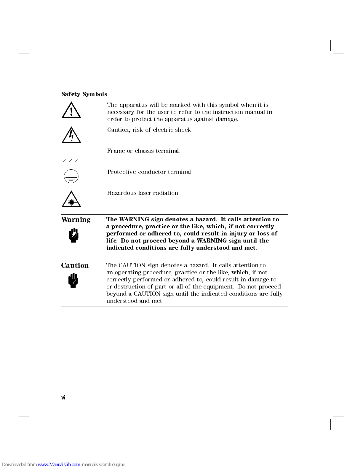
Safety Symbols
The apparatus will be marked with this symbol when it is
necessary for the user to refer to the instruction manual in
order to protect the apparatus against damage.
Caution, risk of electric shock.
Frame or chassis terminal.
Protective conductor terminal.
Hazardous laser radiation.
Warning
Caution
The WARNING sign denotes a hazard. It calls attention to
a procedure, practice or the like, which, if not correctly
performed or adhered to, could result in injury or loss of
life. Do not proceed beyond a WARNING sign until the
indicated conditions are fully understood and met.
The CAUTION sign denotes a hazard. It calls attention to
an operating procedure, practice or the like, which, if not
correctly performed or adhered to, could result in damage to
or destruction of part or all of the equipment. Do not proceed
beyond a CAUTION sign until the indicated conditions are fully
understood and met.
vi
Page 7
Initial Safety Information for the Tunable Laser
Source
The Specications for these instruments are as follows:
Laser Type
Laser Class
According to 21 1 1 1 IIIb
CFR 1040.10 (USA)
According to 3A 3A 3A 3A
IEC 825-1 (Non-USA)
EN 60825-1 Europe
Permissible Output Power (CW)
Beam Diameter
Numerical Aperture
Wavelength
HP 8167A HP 8168D HP 8168E HP 8168F
Fabry Fabry Fabry Fabry
Perot-Laser Perot-Laser Perot-Laser Perot-Laser
InGaAsP InGaAsP InGaAsP InGaAsP
<
1.6mW
9m 9m 9m 9m
0.1 0.1 0.1 0.1
1280-1330nm 1490-1565nm 1475-1575nm 1450-1590nm
<
1.6mW
<
1.6mW
<
9.9mW
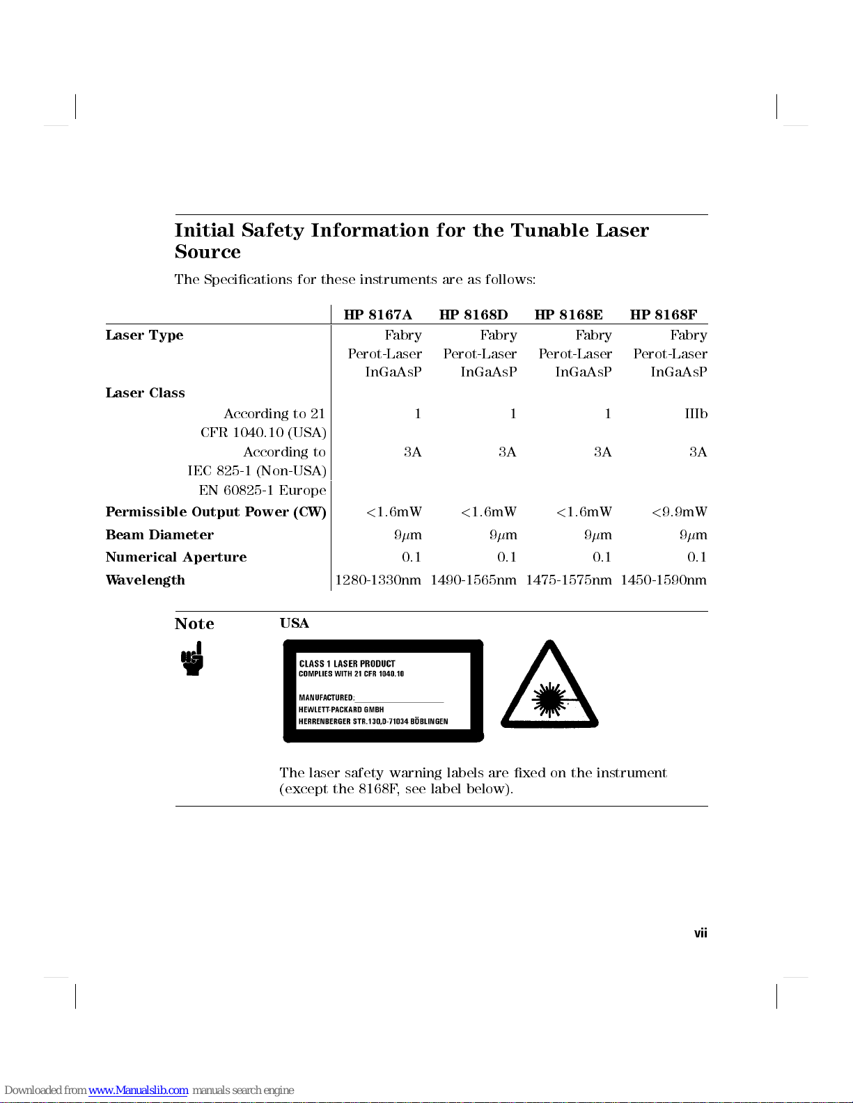
Note
USA
The laser safety warning labels are xed on the instrument
(except the 8168F, see label below).
vii
Page 8
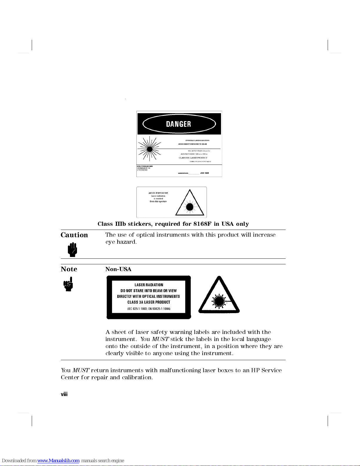
Class IIIb stickers, required for 8168F in USA only
Caution
Note
You
MUST
Center for repair and calibration.
viii
The use of optical instruments with this product will increase
eye hazard.
Non-USA
A sheet of laser safety warning labels are included with the
instrument. You
onto the outside of the instrument, in a position where they are
clearly visible to anyone using the instrument.
return instruments with malfunctioning laser boxes to an HP Service
MUST
stick the labels in the local language
Page 9
The instrument has built in safety circuitry that will disable the optical output
in the case of a fault condition.
Warning
Warning
Warning
Warning
Use of controls or adjustments or performance of
procedures other than those specied for the laser source
may result in hazardous radiation exposure.
Refer Servicing only to qualied and authorized personnel.
Do not enable the laser when there is no ber attached to
the optical output connector.
The optical output connector is at the bottom right of the
instrument front panel.
The laser is enabled by pressing the gray button beside
the optical output connector on the front panel. The laser
is enabled when the green LED on the front panel of the
instrument is lit.
Under no circumstances look into the end of an optical
cable attached to the optical output when the device is
operational.
The laser radiation is not visible to the human eye, but it
can seriously damage your eyesight.
ix
Page 10
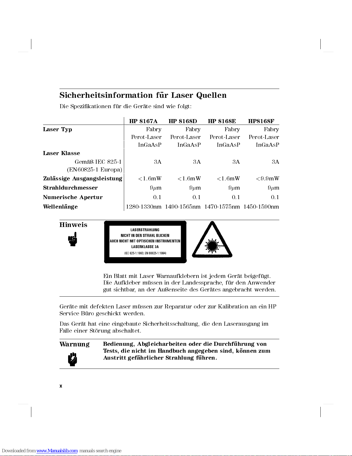
Sicherheitsinformation fur Laser Quellen
Die Spezikationen f ur die Ger ate sind wie folgt:
HP 8167A HP 8168D HP 8168E HP8168F
Laser Typ
Laser Klasse
Gem a IEC 825-1 3A 3A 3A 3A
(EN60825-1 Europa)
Zulassige Ausgangsleistung
Strahldurchmesser
Numerische Apertur
Wellenl
ange
Hinweis
1280-1330nm 1490-1565nm 1470-1575nm 1450-1590nm
Fabry Fabry Fabry Fabry
Perot-Laser Perot-Laser Perot-Laser Perot-Laser
InGaAsP InGaAsP InGaAsP InGaAsP
<
1.6mW
9m 9m 9m 9m
0.1 0.1 0.1 0.1
<
1.6mW
<
1.6mW
<
9.9mW
Ein Blatt mit Laser Warnaufklebern ist jedem Ger at beigef ugt.
Die Aufkleber m ussen in der Landessprache,fur den Anwender
gut sichtbar, an der Auenseite des Ger ates angebracht werden.
Ger ate mit defekten Laser m ussen zur Reparatur oder zur Kalibration an ein HP
Service B uro geschickt werden.
Das Ger at hat eine eingebaute Sicherheitsschaltung, die den Laserausgang im
Falle einer St orung abschaltet.
Warnung
x
Bedienung, Abgleicharbeiten oder die Durchfuhrung von
Tests, die nicht im Handbuch angegeben sind, konnen zum
Austritt gefahrlicher Strahlung fuhren.
Page 11

Warnung
Reparaturarbeiten durfen nur von qualiziertem und
bevollmachtigtem Personal durchgefuhrt werden.
Warnung
Warnung
Laser nicht ohne angeschlossenes Glasfaserkabel
einschalten.
Der optische Ausgang bendet sich am unteren rechten
Teil der Frontplatte. Mit dem danebenliegenden grauen
Druckschalter wird der Laser ein- bzw. ausgeschaltet. Bei
eingeschaltetem Laser leuchtet eine grune LED an der
Frontplatte des Einschubes.
Wenn der Laser eingeschaltet ist, darf unter keinen
Umstanden in das Ende des optischen Kabels oder in den
Laserausgang am Gerat geschaut werden.
Der Laserstrahl ist fur das menschliche Auge unsichtbar,
kann aber das Sehvermogen ernsthaft verletzen.
xi
Page 12
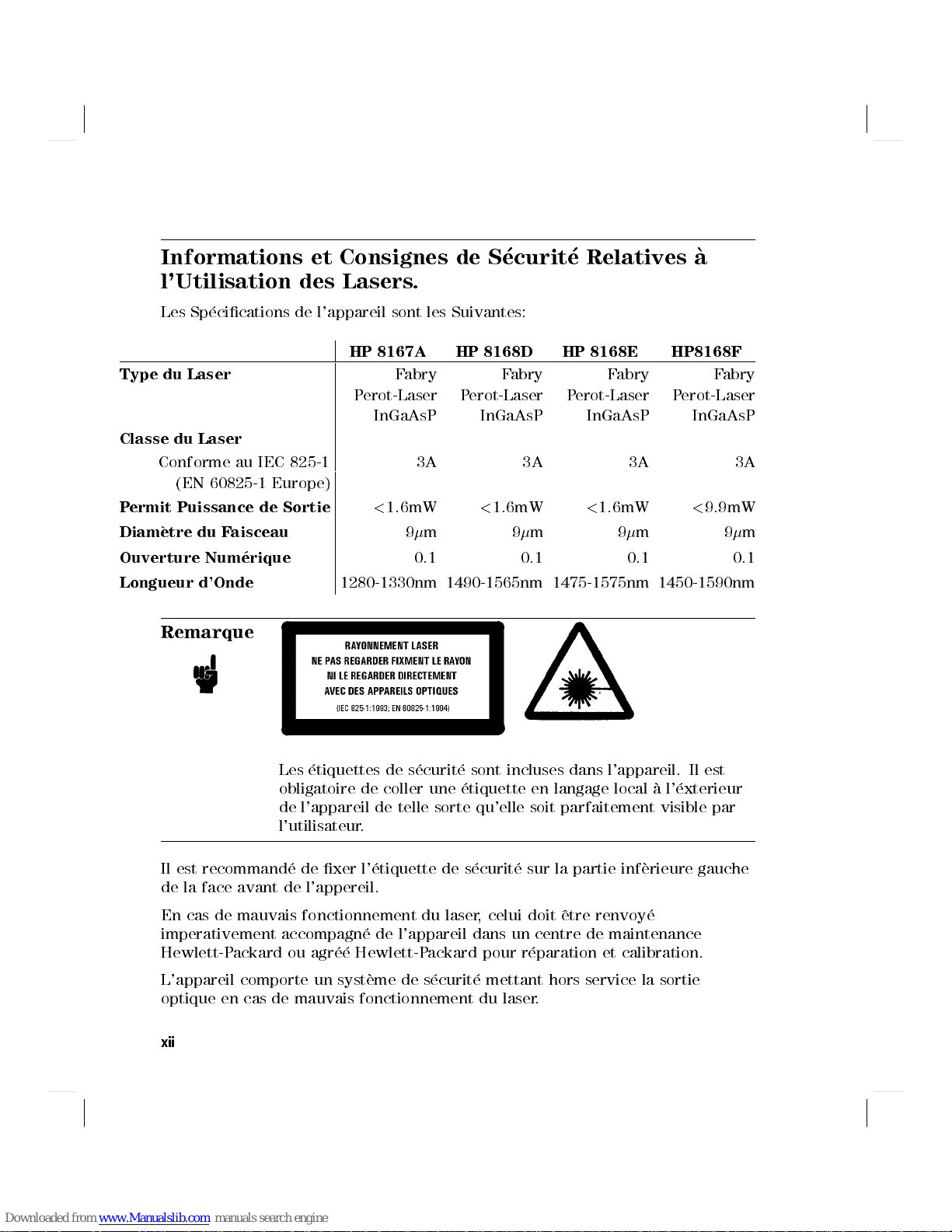
Informations et Consignes de Securite Relativesa
l'Utilisation des Lasers.
Les Sp ecications de l'appareil sont les Suivantes:
HP 8167A HP 8168D HP 8168E HP8168F
Type du Laser
Classe du Laser
Conforme au IEC 825-1 3A 3A 3A 3A
(EN 60825-1 Europe)
Permit Puissance de Sortie
Diametre du Faisceau
Ouverture Numerique
Longueur d'Onde
Remarque
1280-1330nm 1490-1565nm 1475-1575nm 1450-1590nm
Fabry Fabry Fabry Fabry
Perot-Laser Perot-Laser Perot-Laser Perot-Laser
InGaAsP InGaAsP InGaAsP InGaAsP
<
1.6mW
9m 9m 9m 9m
0.1 0.1 0.1 0.1
<
1.6mW
<
1.6mW
<
9.9mW
Les etiquettes de s ecurit e sont incluses dans l'appareil. Il est
obligatoire de coller une etiquette en langage local al'exterieur
de l'appareil de telle sorte qu'elle soit parfaitement visible par
l'utilisateur.
Il est recommand e de xer l' etiquette de s ecurit e sur la partie inf erieure gauche
de la face avant de l'appereil.
En cas de mauvais fonctionnement du laser, celui doit ^etre renvoy e
imperativement accompagn e de l'appareil dans un centre de maintenance
Hewlett-Packard ou agr ee Hewlett-Packard pour r eparation et calibration.
L'appareil comporte un syst eme de s ecurit e mettant hors service la sortie
optique en cas de mauvais fonctionnement du laser.
xii
Page 13
Attention
L'utilisation du laser en dehors de ses limites de
performances et des procedures denies par HP peut
conduirea une exposition aux radiations dangereuse pour
l'utilisateur.
Attention
Attention
Attention
Seul le personnel autorise par HP est qualie pour
intervenir sur le laser.
Ne pas mettre le laser sous tension sans s'^etre assure
qu'une bre optique est bien xee sur le connecteur.
Le connecteur de sortie optique est situe au bas de la face
avant de l'appareil.
La mise en service du laser s'eectue par la pression du
bouton gris situea cote de la sortie optique au bas de la
face avant de l'appareil. L'illumination de la LED verte
indique que le laser est en activite.
Ne tentez en aucun cas de regarder l'extremite de la bre
optique attachee au connecteur lorsque le laser est en
activite.
Bien que la lumiereemise par le laser ne soit pas visible elle
peut cependant^etre dangereuse pour la vue.
xiii
Page 14
Introduction
This guide is arranged into four categories:
Getting Started
This section gives an introduction to the instrument, and aims to make the
instrument familiar to you: Chapter 1.
Local Control
This is the information on how to control the instrument from the front panel:
Chapters 2 and 3.
Remote Control
This is the information on how to control the instrument over the HP-IB
is made of general information for using the HP-IB
some programming examples.: Chapters 4, 5, and 6.
Additional Information
This is supporting information of a non-operational nature. This contains
installation information, accessories, specications, function tests, cleaning
procedures, and error codes: Appendices A through G.
, a command reference, and
. This
Attenuator
xiv
Some information in this manual applies only to the tunable
laser source with the built in optical attenuator (option 003).
This paragraph is marked the way that all the passages which
only apply to the attenuator option are marked in this manual.
Page 15
Contents
1. Getting Started
What is a Tunable Laser Source? ................ 1-1
A description of the Front Panel .. ...... ...... .. 1-2
Starting the 8168F . . . . . . . . . . . . . . . . . . . . . . . 1-3
Getting Help . . . . . . . . . . . . . . . . . . . . . . . . . . 1-4
Changing the Value of a Parameter ............... 1-5
Making Big Changes to a Parameter . . . . . . . . . . . . . . 1-6
Making a Small Change to a Parameter ............ 1-6
Setting a Parameter to its Default Value . . . . . . . . . . . . 1-7
If You Make a Mistake .. ...... ...... ..... . 1-7
If the Parameter Will Not Change . . . . . . . . . . . . . . . 1-8
A Sample Session ...... ...... ...... ..... 1-8
Measuring the Power of a Modulated Signal . . . . . . . . . . 1-8
Setting the Wavelength . . . . . . . . . . . . . . . . . . . 1-9
Setting the Modulated Power . . . . . . . . . . . . . . . . 1-9
Measuring a Wavelength Characteristic ............ 1-11
Setting Up the Wavelength Sweep ............. 1-11
Performing the Wavelength Characteristic Measurement ... 1-12
2. Setting Wavelength and Power
Setting the Wavelength . . . . . . . . . . . . . . . . . . . . . 2-2
Setting the Wavelength Directly ...... ...... ... 2-2
Setting a Relative Wavelength ...... ...... .... 2-3
Changing the Base Wavelength . . . . . . . . . . . . . . . 2-3
Performing a Wavelength Sweep ................ 2-4
Setting the Wavelength Sweep ................ 2-5
Setting the Maximum Power for the Sweep Range . . . . . . . 2-5
Executing an Automatic Sweep . . . . . . . . . . . . . . . . 2-6
Performing a Manual Sweep ........ ...... ... 2-6
Setting the Power ....................... 2-8
Setting the Output Power of a CW Signal ........... 2-8
Setting Power and Attenuation . . . . . . . . . . . . . . . 2-9
Contents-1
Page 16

What is Excessive Power? .................. 2-9
The Analog Output ..................... 2-9
Setting a Modulated Signal . . . . . . . . . . . . . . . . . . . 2-10
Using the Internal Modulation ................ 2-11
Setting the Output Power of a Modulated Signal . . . . . . . 2-11
Setting the Frequency of a Modulated Signal ........ 2-11
The Modulation Output .................. 2-12
Using External Modulation . . . . . . . . . . . . . . . . . . 2-12
Setting the Output Power of a Modulated Signal . . . . . . . 2-13
The Modulation Input .. ...... ...... ..... 2-13
Using Coherence Control . . . . . . . . . . . . . . . . . . . . 2-13
Setting the Output Power of a Coherence Control Signal .... 2-13
The Coherence Control Uncal Power ............. 2-14
3. Other Functions
Storing and Recalling Instrument Settings . . . . . . . . . . . . 3-1
Using the System Utilities ................... 3-2
Switching the Instrument into Stand-By . . . . . . . . . . . . 3-3
Increasing the Lifetime of the Display . . . . . . . . . . . . 3-3
Setting the HP-IB Address .................. 3-4
Setting the Modulation Output .... ...... ...... 3-4
Getting Information about the Instrument . . . . . . . . . . . 3-4
Setting the Date and Time ...... ...... ...... 3-4
Performing a Selftest . . . . . . . . . . . . . . . . . . . . .
Auxiliary Functions ........ ...... ...... .. 3-6
Viewing the Power as a Function of Wavelength . . . . . . . . 3-6
Setting the Peak Power ................... 3-7
Passive Component Test (PACT).. ...... ...... .. 3-7
Automatic Realignment ................... 3-7
Secure .......... ...... ...... ..... 3-9
Lock the Instrument . . . . . . . . . . . . . . . . . . . . 3-9
Change the Password .. ...... ..... ...... 3-11
3-5
4. Programming the Tunable Laser Source
HP-IB Interface ........................ 4-1
Setting the HP-IB Address .. ...... ...... ..... 4-3
Returning the Instrument to Local Control ........... 4-3
How the Tunable Laser Source Receives and Transmits Messages . 4-3
How the Input Queue Works ................. 4-3
Clearing the Input Queue . . . . . . . . . . . . . . . . . . 4-4
The Output Queue . . . . . . . . . . . . . . . . . . . . . . 4-4
Contents-2
Page 17
The Error Queue . . . . . . . . . . . . . . . . . . . . . . . 4-4
Some Notes about Programming and Syntax Diagram Conventions 4-5
Short Form and Long Form.................. 4-5
Command and Query Syntax ................. 4-5
5. Remote Commands
Units ............................. 5-1
Command Summary ...................... 5-2
The Common Commands . . . . . . . . . . . . . . . . . . . . 5-5
Common Status Information ................. 5-5
SRQ, The Service Request ................. 5-6
*CLS ............................ 5-7
*ESE ............................ 5-7
*ESE? . . . . . . . . . . . . . . . . . . . . . . . . . . . 5-8
*ESR? . . . . . . . . . . . . . . . . . . . . . . . . . . . . 5-8
*IDN? . . . . . . . . . . . . . . . . . . . . . . . . . . . . 5-9
*OPC . . . . . . . . . . . . . . . . . . . . . . . . . . . . 5-10
*OPC? ........ ...... ...... ...... 5-10
*OPT? ...... ...... ...... ...... ... 5-10
*RCL ............................ 5-11
*RST ............................ 5-11
*SAV ............................ 5-12
*SRE ............................
*SRE? . . . . . . . . . . . . . . . . . . . . . . . . . . .
*STB? . . . . . . . . . . . . . . . . . . . . . . . . . . . . 5-13
*TST? . . . . . . . . . . . . . . . . . . . . . . . . . . . . 5-14
*WAI ............................ 5-16
:DISPlay Commands ...................... 5-16
:DISPlay:ENABle ...................... 5-16
:DISPlay:ENABle? . . . . . . . . . . . . . . . . . . . . . 5-16
:LOCK Commands ...... ...... ...... ..... 5-17
:LOCK ........................... 5-17
:LOCK? . . . . . . . . . . . . . . . . . . . . . . . . . . . 5-17
:OUTPut Commands ...... ...... ...... .... 5-17
:OUTPut[:STATe].... ...... ...... ...... . 5-17
:OUTPut[:STATe]? ........ ...... ...... . 5-18
[:SOURce] Commands ..................... 5-18
[:SOURce]:AM:INTernal:FREQuency . . . . . . . . . . . . . . 5-18
[:SOURce]:AM:INTernal:FREQuency? ...... ...... 5-19
[:SOURce]:AM:SOURce . . . . . . . . . . . . . . . . . . . . 5-19
[:SOURce]:AM:SOURce? .................. 5-19
5-12
5-13
Contents-3
Page 18
[:SOURce]:AM:STATe......... ...... ...... 5-20
[:SOURce]:AM:STATe? ................... 5-20
[:SOURCE]:MODOUT . . . . . . . . . . . . . . . . . . . . . 5-21
[:SOURCE]:MODOUT? ........ ...... ..... 5-21
[:SOURce]:POWer:ATTenuation .... ...... ...... 5-22
[:SOURce]:POWer:ATTenuation? . . . . . . . . . . . . . . . 5-22
[:SOURce]:POWer:ATTenuation:AUTO............. 5-23
[:SOURce]:POWer:ATTenuation:AUTO? ........... 5-23
[:SOURce]:POWer:ATTenuation:DARK............. 5-24
[:SOURce]:POWer:ATTenuation:DARK? ........... 5-24
[:SOURce]:POWer[:LEVel][:IMMediate][:AMPlitude] . . . . . . . 5-25
[:SOURce]:POWer[:LEVel][:IMMediate][:AMPlitude]? ..... 5-25
[:SOURce]:POWer:UNIT ................... 5-26
[:SOURce]:POWer:UNIT? .. ...... ...... .... 5-26
[:SOURce]:WAVElength[:CWj:FIXED] ...... ...... . 5-27
[:SOURce]:WAVElength[:CWj:FIXED]? . . . . . . . . . . . . 5-27
[:SOURce]:WAVElength:REFerence? . . . . . . . . . . . . . . 5-28
[:SOURce]:WAVElength:REFerence:DISPlay .......... 5-28
[:SOURce]:WAVElength:FREQuency . . . . . . . . . . . . . . 5-28
[:SOURce]:WAVElength:FREQuency? ............ 5-28
:STATus Commands ...................... 5-29
:STATus:OPERation:CONDition? ............... 5-30
:STATus:OPERation:ENABle .................
:STATus:OPERation:ENABle? . . . . . . . . . . . . . . . .
:STATus:OPERation[:EVENt]? . . . . . . . . . . . . . . . . . 5-31
:STATus:OPERation:NTRansition ........ ...... . 5-32
:STATus:OPERation:NTRansition? . . . . . . . . . . . . . . 5-32
:STATus:OPERation:PTRansition ............... 5-32
:STATus:OPERation:PTRansition? . . . . . . . . . . . . . . 5-32
:STATus:QUEStionable:CONDition? .............. 5-33
:STATus:QUEStionable:ENABle . . . . . . . . . . . . . . . . 5-33
:STATus:QUEStionable:ENABle? .............. 5-33
:STATus:QUEStionable[:EVENt]? ............... 5-34
:STATus:QUEStionable:NTRansition . . . . . . . . . . . . . . 5-34
:STATus:QUEStionable:NTRansition? .......... .. 5-34
:STATus:QUEStionable:PTRansition . . . . . . . . . . . . . . 5-35
:STATus:QUEStionable:PTRansition? ............ 5-35
:STATus:PRESet ...... ...... ...... ..... 5-35
:SYSTem Commands ...................... 5-36
:SYSTem:DATe........................ 5-36
:SYSTem:DATe? .. ...... ...... ...... .. 5-36
5-31
5-31
Contents-4
Page 19
:SYSTem:ERRor? . . . . . . . . . . . . . . . . . . . . . . . 5-36
:SYSTem:TIMe . . . . . . . . . . . . . . . . . . . . . . . . 5-37
:SYSTem:TIMe? ...................... 5-37
:TRACe Commands . . . . . . . . . . . . . . . . . . . . . . . 5-37
:TRACe:CATalog? ........ ...... ...... .. 5-37
:TRACe:POINts?<trace name>............... 5-38
:TRACe[:DATa]?<trace name>...... ...... .... 5-38
Other Commands ....................... 5-38
WAVEACT.......................... 5-38
6. Programming Examples
Example 1 - Checking Communication ............. 6-2
Example 2 - Status Registers and Queues ............ 6-3
Example 3 - Measuring the Power of a Modulated Signal . . . . . 6-7
Example 4 - Measuring a Wavelength Characteristic .. ..... 6-10
Example 5 - Increased Tuning Linearity . . . . . . . . . . . . . 6-12
A. Installation
Safety Considerations ..................... A-1
Initial Inspection . . . . . . . . . . . . . . . . . . . . . . . . A-1
AC Line Power Supply Requirements ........ ...... A-2
Line Power Cable .......... ..... ...... . A-2
Changing the Battery ...... ...... ...... ..
Changing the Fuse . . . . . . . . . . . . . . . . . . . . . .
Operating and Storage Environment .. ...... ...... A-6
Temperature . . . . . . . . . . . . . . . . . . . . . . . . . A-6
Humidity .......................... A-6
Instrument Positioning and Cooling . . . . . . . . . . . . . . A-6
Switching on the Tunable Laser Source ............. A-7
Self test . . . . . . . . . . . . . . . . . . . . . . . . . . . A-7
Initializing . . . . . . . . . . . . . . . . . . . . . . . . . . A-7
Stabilizing . . . . . . . . . . . . . . . . . . . . . . . . . . A-8
Stabilizing during Operation ................ A-8
Signal Outputs. ........................ A-9
Optical Output . . . . . . . . . . . . . . . . . . . . . . . . . A-9
HP-IB Interface ........................ A-10
Connector . . . . . . . . . . . . . . . . . . . . . . . . . . A-10
HP-IB Logic Levels . . . . . . . . . . . . . . . . . . . . . . A-11
Claims and Repackaging .................... A-12
Return Shipments to HP ................... A-12
A-4
A-4
Contents-5
Page 20
B. Accessories
Mainframe .......................... B-1
Options . . . . . . . . . . . . . . . . . . . . . . . . . . . B-2
Option 003: ........................ B-2
Option 007: ........................ B-2
Connector Interfaces and Other Accessories . . . . . . . . . B-2
Option 021, Straight Contact Connector . . . . . . . . . . B-3
Option 022, Angled Contact Connector .......... B-4
Option 023, Diamond HMS-10/HRL Angled, Non-Contact
Connector ...................... B-5
HP-IB Cables and Adapters . . . . . . . . . . . . . . . . . . . B-7
C. Specications
Denition of Terms ...................... C-1
Performance Specications . . . . . . . . . . . . . . . . . . . C-4
Supplementary Performance Characteristics . . . . . . . . . . . C-7
Characteristics . . . . . . . . . . . . . . . . . . . . . . . . C-7
Operating Modes . . . . . . . . . . . . . . . . . . . . . . . C-7
Internal Modulation .................... C-7
External modulation . . . . . . . . . . . . . . . . . . . . C-7
Coherence Control . . . . . . . . . . . . . . . . . . . . . C-7
General . . . . . . . . . . . . . . . . . . . . . . . . . . . C-7
Polarization maintaining ber . . . . . . . . . . . . . . . .
HP-IB Interface ......................
Passive Component Test Software . . . . . . . . . . . . . . C-8
Laser Class ........................ C-8
Environmental ........ ...... ...... .. C-8
Listed options . . . . . . . . . . . . . . . . . . . . . . . C-9
Other Specications ...................... C-9
Declaration of Conformity ................... C-10
C-7
C-8
D. Performance Tests
Introduction . . . . . . . . . . . . . . . . . . . . . . . . . . D-1
Equipment Required . . . . . . . . . . . . . . . . . . . . . . D-1
Test Record .......................... D-2
Test Failure .......................... D-3
Instrument Specication .................... D-3
Wavelength Tests ....................... D-3
Relative Wavelength Accuracy ................ D-5
Wavelength Repeatability .. ...... ...... .... D-6
Power Tests . . . . . . . . . . . . . . . . . . . . . . . . . . D-7
Contents-6
Page 21
Maximum Output Power .... ...... ...... ... D-7
Power Linearity . . . . . . . . . . . . . . . . . . . . . . . D-10
Power Flatness over Wavelength ............... D-14
Power Stability .......... ...... ...... . D-15
Source Spontaneous Emission ................. D-16
E. Cleaning Procedures
The Cleaning Kit . . . . . . . . . . . . . . . . . . . . . . . . E-1
Other Cleaning Tools . . . . . . . . . . . . . . . . . . . . . E-3
Preserving Connectors . . . . . . . . . . . . . . . . . . . . . E-4
Cleaning Instrument Housings ................. E-4
Cleaning Procedures . . . . . . . . . . . . . . . . . . . . . . E-5
Cleaning Cable Connectors . . . . . . . . . . . . . . . . . . E-5
Cleaning Connector Adapters . . . . . . . . . . . . . . . . . E-6
Cleaning Connector Interfaces ................ E-7
Cleaning Bare Fiber Adapters . . . . . . . . . . . . . . . . . E-8
Cleaning Bare Fiber Ends .. ...... ..... ..... E-8
Cleaning Lenses . . . . . . . . . . . . . . . . . . . . . . . E-9
Cleaning Large Area Lenses and Mirrors . . . . . . . . . . . . E-10
Cleaning Fixed Connector Interfaces .......... ... E-11
Cleaning Optical Glass Plates . . . . . . . . . . . . . . . . . E-11
Cleaning Physical Contact Interfaces .... ...... ... E-11
Cleaning Recessed Lens Interfaces .............. E-12
Cleaning Fragile Optical Devices ........ ...... . E-12
Cleaning Metal Filters or Attenuator Gratings ......... E-13
F. Error Messages
Display Messages ........ ...... ...... ... F-1
HP-IB Messages ........................ F-3
Instrument Specic Errors .................. F-3
Command Errors . . . . . . . . . . . . . . . . . . . . . . . F-3
Execution Errors ...................... F-6
Device-Specic Errors .... ...... ...... .... F-7
Query Errors ........................ F-8
Contents-7
Page 22
G. Backdating
Initial Safety Information for the Tunable Laser Source ..... G-1
Earlier models . . . . . . . . . . . . . . . . . . . . . . . . . G-1
Specications ......................... G-2
Performance Specications . . . . . . . . . . . . . . . . . . G-2
Supplementary Performance Characteristics . . . . . . . . . G-2
Index
Contents-8
Page 23
Figures
1-1. The Tunable Laser Source Front Panel ...... ...... 1-2
1-2. Starting Screen for the 8168F . . . . . . . . . . . . . . . . . 1-3
1-3. \Secure: Unlock Instrument" Screen ............. 1-4
1-4. \Secure" Screen . . . . . . . . . . . . . . . . . . . . . . . 1-4
1-5. A Summary of the Help Hard- and Softkeys . . . . . . . . . . 1-5
1-6. The Help Topics Menu .................... 1-5
1-7. Connecting the Instruments for the Sample Session .. .... 1-9
1-8. Tunable Laser Source Display after Setting Up W
Power . . . . . . . . . . . . . . . . . . . . . . . . . .
1-9. Tunable Laser Source Display during Setting Up for the
Wavelength Sweep .................... 1-11
2-1. A Summary of the additional Output Power Softkeys for the
Attenuator Option .................... 2-2
2-2. Setting the Wavelength Directly .... ...... ..... 2-2
2-3. Setting a Relative Wavelength .......... ...... 2-3
2-4. Setting Up for a Wavelength Sweep . . . . . . . . . . . . . . 2-4
2-5. The Parameters for a Wavelength Sweep .......... . 2-5
2-6. Performing a Manual Sweep ...... ...... ..... 2-7
2-7. Setting the Output Power of a CW Signal ........... 2-8
2-8. The Modulated Signal .................... 2-11
2-9. Setting the Output Power of an Internally Modulated Signal .. 2-11
2-10. External Modulation and Output Power . . . . . . . . . . . . 2-12
2-11. Setting the Output Power of an Externally Modulated Signal . . 2-13
2-12. Setting the Output Power of a Coherence Controlled Signal . . . 2-14
2-13. The Coherence Control Uncalibrated Power and the Maximum
Power Level ....................... 2-14
3-1. User Setting Number 1 . . . . . . . . . . . . . . . . . . . . 3-1
3-2. Summary of the Setting Hard- and Softkeys . . . . . . . . . . 3-2
3-3. The System Screen . . . . . . . . . . . . . . . . . . . . . . 3-3
3-4. Summary of the System Hard- and Softkeys . . . . . . . . . . 3-3
3-5. Auxiliary Functions (8167A, 8168D/E) . . . . . . . . . . . . . 3-6
3-6. Auxiliary Functions (8168F) ................. 3-6
avelength and
1-10
Contents-9
Page 24
3-7. Auto Realignment ...................... 3-8
3-8. \Secure" screen . . . . . . . . . . . . . . . . . . . . . . . 3-9
3-9. \Secure: Lock Instrument" screen .............. 3-10
3-10. \Secure" screen - instrument is locked .... ...... .. 3-10
3-11. \Secure: Unlock Instrument" screen ............. 3-10
3-12. \Secure: Change Password" screen . . . . . . . . . . . . . . 3-11
3-13. \Secure: Change Password": Enter new password . . . . . . . 3-11
3-14. \Secure: Change Password": Enter new password again . . . . 3-11
5-1. Common Status Registers . . . . . . . . . . . . . . . . . . . 5-6
5-2. The Status Registers . . . . . . . . . . . . . . . . . . . . . 5-30
6-1. Connecting the Instruments for the Sample Session .... .. 6-8
6-2. Measurement setup for Increased Tuning Linearity ...... 6-12
6-3. Flow chart describing Increased Tuning Linearity program. . . . 6-13
A-1. Line Power Cables - Plug Identication ............ A-2
A-2. Rear Panel Markings . . . . . . . . . . . . . . . . . . . . . A-4
A-3. Releasing the Fuse Holder .......... ...... .. A-5
A-4. The Fuse Holder . . . . . . . . . . . . . . . . . . . . . . . A-5
A-5. Correct Positioning of the Tunable Laser Source . . . . . . . . A-7
A-6. PMF Output . . . . . . . . . . . . . . . . . . . . . . . . . A-10
A-7. HP-IB Connector . . . . . . . . . . . . . . . . . . . . . . . A-11
B-1. Tunable Laser Source Options Overview . . . . . . . . . . . . B-2
B-2. Tunable Laser Source Option 021 Conguration ........ B-3
B-3. Tunable Laser Source Option 022 Conguration ........ B-5
B-4. Tunable Laser Source Option 023 Conguration ........ B-6
C-1. Maximum Specied Output Power for 8168D, E and F (without
options) ......................... C-1
D-1. Test Setup for the Wavelength Tests . . . . . . . . . . . . . . D-4
D-2. Test Setup for the Maximum Output Power Test (except HP
8168F) . . . . . . . . . . . . . . . . . . . . . . . . . . D-8
D-3. Test Setup for the Maximum Output Power Test (HP 8168F only) D-9
D-4. Test Setup for the Power Tests (except Maximum Output Power) D-11
D-5. Test Setup for the Source Spontaneous Emission Test...... D-17
Contents-10
Page 25
Tables
4-1. HP-IB Capabilities . . . . . . . . . . . . . . . . . . . . . . 4-2
5-1. Units and Allowed Mnemonics ................ 5-1
5-2. Common Command Summary . . . . . . . . . . . . . . . . . 5-2
5-3. Command List . . . . . . . . . . . . . . . . . . . . . . . . 5-3
5-4. Reset State (Default Setting) .... ...... ...... . 5-12
5-5. Specied Wavelength range . . . . . . . . . . . . . . . . . . 5-27
6-1. Program Description: Increased Tuning Linearity ...... . 6-16
A-1. Temperature . . . . . . . . . . . . . . . . . . . . . . . . . A-6
Contents-11
Page 26

Page 27
Getting Started
This chapter gives you basic information on how you can operate the tunable
laser source from the front panel.
What is a Tunable Laser Source?
A tunable laser source is a laser source for which the wavelength is not xed.
The Hewlett-Packard tunable laser sources also allow you to set the output
power, and to choose between continuous wave or modulated output power
.
1
1
Note
The single greatest factor aecting the performance of the
tunable laser source, as with all ber optic measurements, is the
cleanliness of the connectors. Ensure that your connectors are
always clean. For cleaning instructions, see Appendix E.
Getting Started 1-1
Page 28

1
A description of the Front Panel
Figure 1-1. The Tunable Laser Source Front Panel
A softkey is a key whose function changes depending on the keys that you have
pressed before. The function of a softkey is shown on the display above the
softkey.
The memory card drive allows you to load replacement, or additional, software
to increase the capabilities of your tunable laser source.
There are six function keys. These allow you
to set the wavelength, or to perform a wavelength sweep.
to set the output power,
to save the wavelength and output power setting,
to check or change the system conguration: to test the instrument, to switch
o the laser and display, to change the HP-IB Address, to select whether the
internal modulation signal is available at the Modulation Output constantly,
or only when the power is being output, or to get information about the
instrument and the software revision,
to get help information (see \Getting Help" in the next section of this
chapter), or
to perform an auxiliary application such as examine the power characteristic,
or to set the instrument for maximum power output.
The numeric keypad, the cursor keys, and the modify knob are used to edit
parameters.
1-2 Getting Started
Page 29
The modulation output gives a TTL level signal of the same frequency as the
internal modulating signal.
The modulation input allows you to input a signal to modulate the power of the
optical output.
The analog output gives a dc-signal proportional to the output power. The
relationship between this voltage level and the output power is not calibrated,
but is approximately 1mV for each 1W.
At the back of the 8168F, you also have a Remote Interlock Connector. This
is to protect the user from injury. If the short-circuit at this BNC connector is
opened, the laser is switched o immediately and cannot be switched on until it
is closed again.
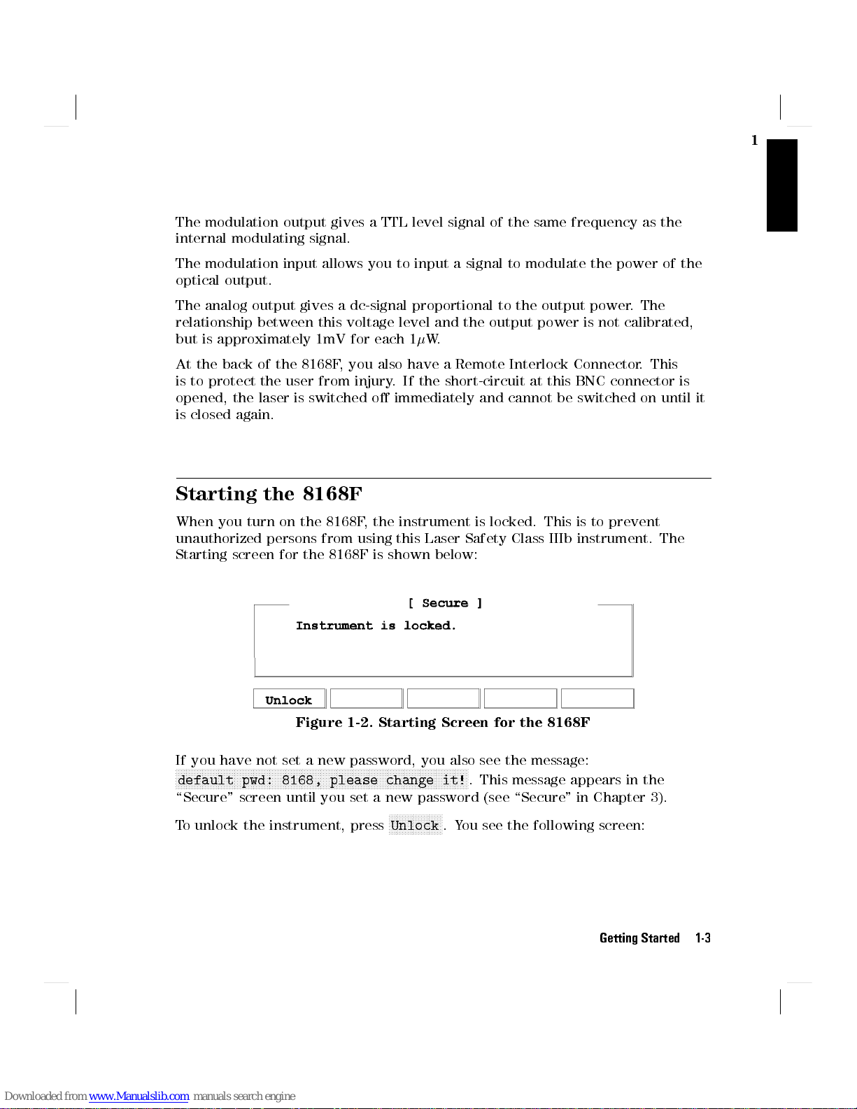
Starting the 8168F
When you turn on the 8168F, the instrument is locked. This is to prevent
unauthorized persons from using this Laser Safety Class IIIb instrument. The
Starting screen for the 8168F is shown below:
1
If you have not set a new password, you also see the message:
NNNNNNNNNNNNNNNNNNNNNNNNNNNNNNNNNNNNNNNNNNNNNNNNNNNNNNNNNNNNNNNNNNNNNNNNNNNNNNNNNNNNNNNNNNNNNNNNNNNNNNNNNNNNN
default pwd: 8168, please change it!
\Secure" screen until you set a new password (see \Secure" in Chapter 3).
To unlock the instrument, press
Figure 1-2. Starting Screen for the 8168F
. This message appears in the
NNNNNNNNNNNNNNNNNNNN
Unlock
.You see the following screen:
Getting Started 1-3
Page 30
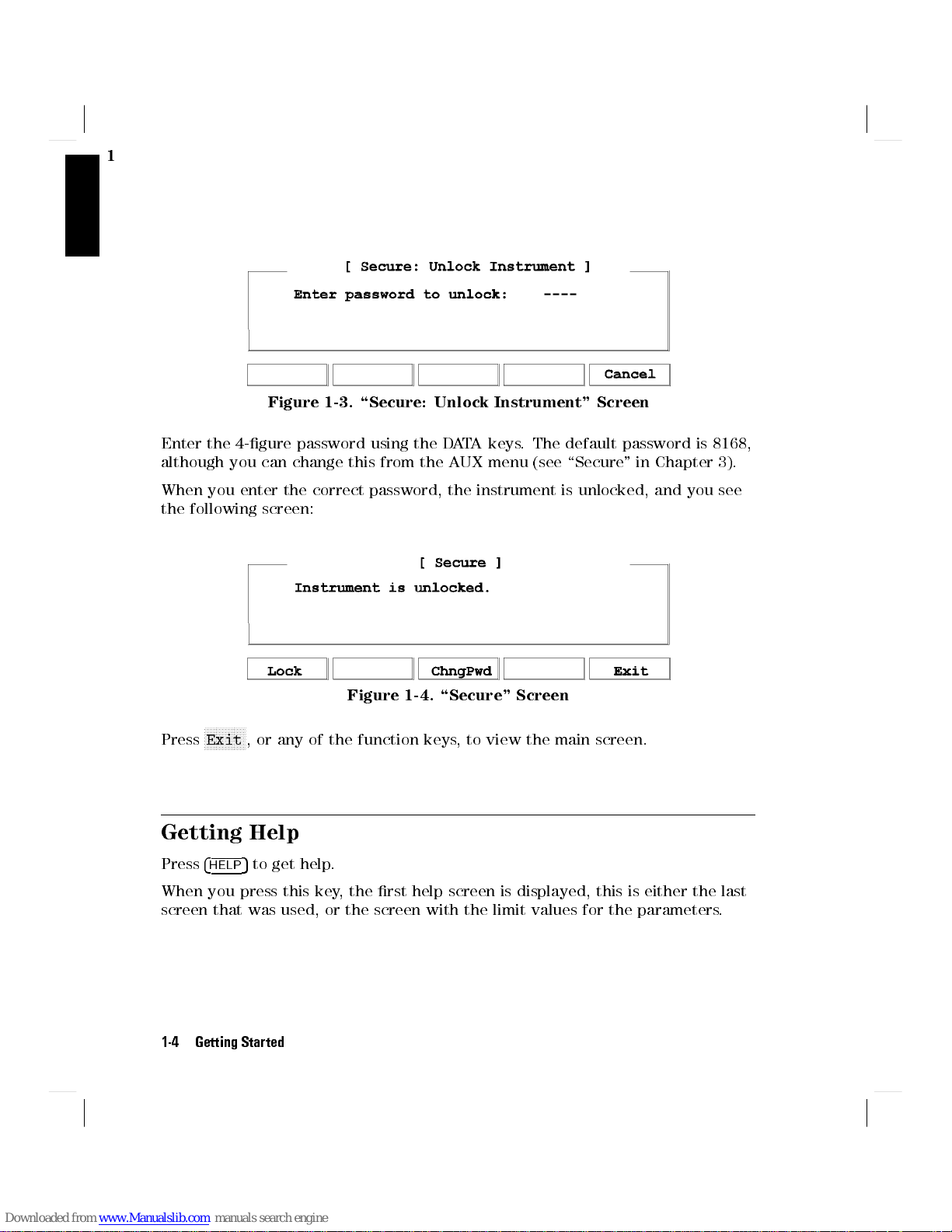
1
Figure 1-3. \Secure: Unlock Instrument" Screen
Enter the 4-gure password using the DATA keys. The default password is 8168,
although you can change this from the AUX menu (see \Secure" in Chapter 3).
When you enter the correct password, the instrument is unlocked, and you see
the following screen:
Figure 1-4. \Secure" Screen
NNNNNNNNNNNNNN
Press
Exit
, or any of the function keys, to view the main screen.
Getting Help
5
Press
4
When you press this key, the rst help screen is displayed, this is either the last
screen that was used, or the screen with the limit values for the parameters.
1-4 Getting Started
HELP
to get help.
Page 31

Press
Figure 1-5. A Summary of the Help Hard- and Softkeys
NNNNNNNNNNNNNNNNNNNN
Search
to get the help topics menu.
Figure 1-6. The Help Topics Menu
1
NNNNN
#
, or the Modify Knob. Press
and
NNNNN
#
.
NNNNN
"
NNNNN
"
and
Choose a topic using
to get the information.
NNNNNNNNNNNNNNNNN
Press
Close
Many of the help texts are longer than one screen. You move between screens
of information using
Changing the Value of a Parameter
What follows is a description of the various methods of changing the value of
parameters on the tunable laser source. Examples in which actual parameter
values are changed are given with the parameter descriptions.
to close the help topics menu without selecting a topic.
NNNNNNNNNNNNNNNNNNNN
Select
,or
4
ENTER
5
Getting Started 1-5
Page 32

1
Making Big Changes to a Parameter
If you are changing the value of a parameter completely, you can directly type
in the value on the keypad, and press
4
ENTER
5
.
Example
Making a Small Change to a Parameter
For small changes to a parameter use
Select the parameter and then:
1. Press
4
EDIT
Modify Knob the cursor moves to the digit that was most recently changed.
If no digit was changed before, or if you started with another key, the cursor
moves to the position of the most signicant digit of the parameter.
To change the output power from 200W to 1025W.
1. Press
2. Type the new value for the output power on the numeric
3. Press
5,4(5.4)5
4
OUTPUT POWER
hand side of the display.
keypad.
5
4
ENTER
, or turn the Modify Knob slightly. If you start with
to end the editing.
5
. The cursor moves to P on the right
:1540.000nm
:1540.000nm P:1025
4
5
, or the Modify Knob.
EDIT
P
: 200W
W
2. If you want to move the cursor and select another digit to edit, use
4)5
.
3. Enter the new value for the digit at the cursor on the keypad, or by turning
the Modify Knob. If you have entered the value from the keypad, the cursor
moves to the next digit.
4. Repeat steps 2 and 3 to continue editing the value.
5. When you have nished editing the value, press
becomes the new value of the parameter.
Example
1-6 Getting Started
To change the wavelength from 1540.000nm to 1542.500nm.
4
ENTER
4(5
5
. The edited value
and
Page 33

1. Press
4
WAVELENGTH
side of the display.
5
. The cursor moves toon the left hand
:1540.000nm P: 200W
1
2. Press
3. Press
4. Press
Setting a Parameter to its Default Value
There is a default softkey that you can use to set a parameter to its default
value.
1. Press
2.
Press
4
5
.
EDIT
NNNNNNNNNNNNNNNNNNNNNN
N
Default
.
4
5
. The cursor moves to the most signicant digit of
EDIT
the wavelength value.
:1
540.000nm P: 200W
4)5
three times to move to the cursor to the units
digit. Press
changes, and the cursor moves to the next digit.
Press
425
on the numeric keypad. The units digit
:1542.000nm P: 200W
5
on the numeric keypad, to change the tenths digit.
4
5
5
4
ENTER
to end the editing.
:1542.500nm P: 200W
If You Make a Mistake
If you make a mistake while you are editing a parameter, you can cancel the
editing, and get the previous value for the parameter back by pressing
Alternatively, you can press
NNNNNNNNNNNNNNNNN
Clear
and type in the parameter again.
Getting Started 1-7
NNNNNNNNNNNNNNNNNNNN
Cancel
.
Page 34

1
If the Parameter Will Not Change
If, when you press
immediately to the previous value for the parameter, then the value you tried to
enter is outside the calibrated range. Press
help topic to see the calibrated range.
A Sample Session
There are two short tasks in this sample session. The rst is to measure the
power of a modulated signal at a single wavelength, and then a wavelength
characteristic at a xed power.
The sample session is written for an HP 8168E/F Tunable Laser Source
an HP 8153A Lightwave Multimeter with an HP 81532A P
is assumed that the power sensor is inserted in channel A). T
sample session as described here, you also need a connector interface for the
multimeter (for example, an HP 81000AI), and a patchcord (if you are using
the HP 81000AI, then a Diamond HMS-10/HP/HRL to Diamond HMS-10/HP
patchcord, HP 81109AC).
These same procedures are repeated in \Example 3 - Measuring the Power of
a Modulated Signal" in Chapter 6 and \Example 4 - Measuring a Wavelength
Characteristic" in Chapter 6, where they are performed using the HP-IB.
4
ENTER
5
after editing, the tunable laser source returns
4
5
, and select the
HELP
ower Sensor (It
Input Limits
o perform the
, and
Measuring the Power of a Modulated Signal
We want to measure the power of a 1540nm signal, modulated by a 100kHz
square wave, at 500W.
1. Make sure that all your connectors and connector interfaces are clean.
2. Make sure that the Optical Output on the laser source is not Active.
3. Connect the output of the laser source to the input of the power sensor (as
shown in the gure below). Make sure that the connector with the orange
strain-relief sleeve is connected to the tunable laser source (the orange
sleeve indicates an angled connector).
1-8 Getting Started
Page 35

Figure 1-7. Connecting the Instruments for the Sample Session
Typically, you would connect a component to test between the tunable laser
source and the power meter.
4. Make sure that both instruments are powered up.
1
Note
Setting the Wavelength
5. On the tunable laser source:
a. Press
b. Make sure that you are setting the wavelength directly.
(Press
on the left side of the display).
c.
Press
6. On the multimeter set the wavelength for the power sensor to 1540.0nm,
set the measurement averaging time to 1s
(
4
5!A;
Chan
Setting the Modulated Power
7. On the tunable laser source:
Normally you also need to be sure that the instruments are
properly warmed up before using the source, or making any
measurements. Here, because the measurements are not critical,
it is okay to proceed immediately to the next step.
5
4
WAVELENGTH
NNNNNNNNNNNNNNNNNNNN
nm/GHz
4
5
and then
EDIT
4
Mode
.
if necessary until there is only one parameter () shown
NNNNNNNNNNNNNNNNNNNNNNN
5!MEAS;4
Default
Param
to set the wavelength to 1540.000nm.
5!!1540.0nm;
4
Param
5!T!1s).
Getting Started 1-9
Page 36

1
5
a. Press
4
OUTPUT POWER
.
b. Make sure that you have a modulated signal selected
(Press
FREQ
c. Make sure that
(the label of the selected parameter is displayed in inverse, press
if it is not selected).
d. Make sure that the power is being shown inWatts
(if necessary, press
e. Type 500 on the keypad and press
8. On the multimeter, make sure that Watts are selected and that the
instrument is autoranging
(
4
dBm/W
9. On the tunable laser source:
a. Press
b. Type in 100 on the keypad.
c. Make sure that the units are set to kHz
(If necessary, press
d. Press
NNNNNNNNNNNNNNNNNNNN
Mod/CW
) shown on the right side of the display).
5!W;
NNNNNNNNNNNNNN
Freq
4
ENTER
if necessary until there are two parameters (
4
Auto
.
5
POWER
5!AUTO
.
is selected
NNNNNNNNNNNNNNNNN
W/dBm
).
NNNNNNNNNNNNNNNNNNNN
Hz/kHz
to change the units).
4
5
ENTER
to change the units).
.
POWER
and
NNNNNNNNNNNNNNNNN
Power
Tunable Laser Source Display after Setting Up Wavelength and Power
10. Press the button beside the Optical Output, the green LED should be lit to
indicate that the laser is now active.
1-10 Getting Started
Figure 1-8.
Page 37

You should notice that the power reading on the multimeter is approximately
half the value set on the laser source. This is because the output is modulated
by a square wave with a 50% duty cycle.
Measuring a Wavelength Characteristic
For the second part, we assume that the instruments are in the state given after
the rst task (see Figure 1-8).
We now want to measure the wavelength characteristic by measuring the power
at 1nm steps between 1535nm and 1545nm, at the highest power level possible
that is available over the full sweep range.
11.
On the laser source, press
operation.
Setting Up the Wavelength Sweep
NNNNNNNNNNNNNNNNNNNN
Mod/CW
to return the laser source to CW
1
12. On the laser source:
a. Press
b. Type in 1535 on the keypad and press
c. Type in 1545 on the keypad and press
d. Type in 1 on the keypad and press
4
WAVELENGTH
for the sweep.
for the sweep.
wavelength step for the sweep.
Tunable Laser Source Display during Setting Up for the Wavelength
5
,and then
NNNNNNNNNNNNNNNNNNNNNN
N
-Sweep
4
ENTER
Figure 1-9.
Sweep
.
5
4
ENTER
4
ENTER
to set the start wavelength
5
to set the stop wavelength
5
to set the size of the
Getting Started 1-11
Page 38

1
e.
f. Type in 1 on the keypad and press
13.
On the laser source, press
value that can be maintained for the full sweep range.
14. On the power meter:
a. Setto 1535nm
b. Make sure that the parameter cursor is in the units position (that is,at
Performing the Wavelength Characteristic Measurement
15. Make sure that the laser source is still active.
16. On the laser source, press
17. Read the value for the power at 1535nm on the multimeter.
18. Repeat the following steps at each wavelength in the sweep range
a.
b. On the multimeter, increment(press
NNNNN
Press
#
to skip over the dwell parameter.
that the sweep is to be performed.
NNNNNNNNNNNNNNNNNNNNNN
Pmax!P
5!!1535.0nm).
(
4
Param
the second \5").
NNNNNNNNNNNNNNNNNNNN
Manual
On the laser source, press
NNNNNNNNNNNNNN
Next
.
.
4
to set the output power to the highest
ENTER
4*5
5
to set the number of times
).
c. Read the value for the power at the wavelength on the multimeter.
19.
On the laser source, press
This procedure can be used in practice to measure the wavelength characteristic
of a component.
1-12 Getting Started
NNNNNNNNNNNNNN
Stop
to end the sweep.
Page 39

2
Setting Wavelength and Power
This chapter describes how to set the wavelength and the power of the output.
2
A Summary of the Wavelength and Output Power Hard- and
Softkeys
Setting Wavelength and Power 2-1
Page 40

2
Figure 2-1.
A Summary of the additional Output Power Softkeys for the
Attenuator Option
Setting the Wavelength
There are three ways to set the wavelength of the tunable laser source.
You can set the wavelength () directly,
You can set the wavelength from a base wavelength and an oset in the
frequency domain, or
You can set a range of wavelengths for the instrument to \sweep"
5
Press
Use
Use
4
WAVELENGTH
NNNNNNNNNNNNNNNNNNNN
nm/GHz
NNNNNNNNNNNNNNNNNNNNNNN
-Sweep
to select how you set the wavelength.
to select the wavelength parameter.
to perform a wavelength sweep.
Setting the Wavelength Directly
You can set the wavelength directly if the display looks like this:
Figure 2-2. Setting the Wavelength Directly
2-2 Setting Wavelength and Power
Page 41

Press
4
WAVELENGTH
See \Changing the Value of a Parameter" in Chapter 1 if you need details on
how to edit parameters.
5
and
NNNNNNNNNNNNNNNNNNNN
nm/GHz
as necessary to get this display.
2
Example
Setting a Relative Wavelength
You use a relative wavelength for heterodyning, for example, when you are
measuring the linewidth of DFB (distributed feedback) lasers.
You can set a relative wavelength if the display looks like this:
Press
4
WAVELENGTH
The output wavelength () is set from the base wavelength (
frequency oset (df). The formula for calculating the output wavelength is:
To set the wavelength to 1505.500nm (on an HP 8168E/F)
1. Press
2.
3. Type in 1505.5 on the numeric keypad, and press
Figure 2-3. Setting a Relative Wavelength
5
4
WAVELENGTH
NNNNNNNNNNNNNNNNNNNN
Press
nm/GHz
in Figure 2-2
NNNNNNNNNNNNNNNNNNNN
and
nm/GHz
5
, if necessary, until the display looks as shown
4
ENTER
as necessary to get to this display.
0) and the
=
c
(
0)df+
0
c
5
.
where c is the speed of light in a vacuum (2.9982108ms-1).
You can edit only the value ofdfdirectly. See \Changing the Value of a
Parameter" in Chapter 1 if you need details on how to edit parameters.
Changing the Base Wavelength
If you want to change
1. setto the value to which you want to set the base wavelength (by
calculatingdf, or by setting the wavelength directly) and then
0,
Setting Wavelength and Power 2-3
Page 42

press
NNNNNNNNNNNNNNNN
!
.
0
Set the base wavelength to 1540.000nm, and then set df, so
that the output wavelength is 1507.5nm (on an HP 8168E/F)
2
2.
Example
1. Press
2.
3.
4.
5.
The base wavelength is now set.
6. Calculate the value for df
c
df
=
0
7. Type in the value for df (4197.0) on the numeric keypad, and
8. Because of inaccuracies in the value taken for the speed of
Performing a Wavelength Sweep
You can perform a wavelength sweep when the screen looks like this
4
WAVELENGTH
NNNNNNNNNNNNNNNNNNN
N
Press
nm/GHz
(that is, to set the wavelength
Press
Press
Press
c
=
0
press
light, this gives avalue of 1507.499nm. Use the Modify
Knob to edit the value for df to get=1507.5nm
5
4
EDIT
NNNNNNNNNNNNNNNNNNNN
nm/GHz
NNNNNNNNNNNNNNNN
!
0
2:998E8
1507:500E0
4
ENTER
5
.
until the screen looks as shown in Figure 2-2
NNNNNNNNNNNNNNNNNNNNNNN
and then
, to set a relative wavelength.
5
.
Default
0
9
1540:000E0
directly
.
2:998E8
).
= 4196:980
9
GH z
Figure 2-4. Setting Up for a Wavelength Sweep
Press
4
WAVELENGTH
2-4 Setting Wavelength and Power
5
and
NNNNNNNNNNNNNNNNNNNNNNN
-Sweep
as necessary to get this display.
Page 43

Setting the Wavelength Sweep
There are ve parameters for the wavelength sweep,
start
, the wavelength with which the sweep begins
stop
, the wavelength at which the sweep ends,
step
, the size of the change in wavelength for each step,
dwell
, the amount of time spent at the wavelength during each step, and
2
,
cycles
You move from one parameter to the next, using
4
ENTER
other parameters onto the display.
See \Changing the Value of a Parameter" in Chapter 1 if you need details on
how to edit parameters.
Setting the Maximum Power for the Sweep Range
NNNNNNNNNNNNNNNNNNNNNN
Pmax!P
Alternatively, you can set a power level in the way described in \Setting the
Power".
, the number of times the sweep is repeated.
Figure 2-5. The Parameters for a Wavelength Sweep
and
NNNNN
#
, the Modify Knob,or
NNNNN
"
5
. Only three of the parameters can be displayed at a time, you scroll the
sets the power to the maximum for the selected sweep range.
Setting Wavelength and Power 2-5
Page 44

2
Note
Executing an Automatic Sweep
You can perform an automatic sweep if you press
sweep parameters, or if you press
NNNNNNNNNNNNNNNNN
Press
Pause
sweep (see \Performing a Manual Sweep").
NNNNNNNNNNNNN
N
Press
Stop
If coherence control is enabled, and the uncal power level
cannot be exceeded for the full wavelength range chosen, the
wavelength range is reduced as necessary.
NNNNNNNNNNNNN
N
Auto
NNNNNNNNNNNNN
N
Cont
during a manual sweep.
to interrupt the sweep. The instrument switches to a manual
to end the sweep.
after setting up the
Example
Performing a Manual Sweep
You can perform a manual sweep if you press
sweep parameters, or if you press
manual sweep the display looks as follows:
Set the instrument to sweep the range 1495nm to 1555nm,
three times, in 1nm steps, stopping for half a second at
each wavelength, at the highest power level available at all
wavelengths.
1.
Press
4
WAVELENGTH
2. Make sure you are at the
3. Type in 1495 and then
4. Type in 1555 and then
5. Type in 1 and then
6. Type in 0.5 and then
7. Type in 3 and then
8.
9. Enable the optical output, if necessary.
10.
Press
Press
NNNNNNNNNNNNNNNNNNNNNN
Pmax!P
N
NNNNNNNNNNNNN
Auto
, to run the application.
5
and then
4
4
4
ENTER
4
ENTER
4
ENTER
, to set the power.
NNNNNNNNNNNNNNNNN
Pause
during an automatic sweep. During a
NNNNNNNNNNNNNNNNNNNNNNN
-Sweep
start
5
ENTER
ENTER
, to set the start wavelength.
5
, to set the stop wavelength.
5
, to set the step size.
5
, to set the dwell time.
5
, to set the number of cycles.
NNNNNNNNNNNNNNNNNNNN
Manual
.
parameter.
after setting up the
2-6 Setting Wavelength and Power
Page 45

Press
Press
Press
Press
NNNNNNNNNNNNNN
Next
NNNNNNNNNNNNNN
Prev
NNNNNNNNNNNNN
N
Cont
NNNNNNNNNNNNNN
Stop
Figure 2-6. Performing a Manual Sweep
to move on to the next wavelength step
to move back to the previous wavelength step.
to continue with an automatic sweep, from the current wavelength.
to end the sweep.
.
2
Setting Wavelength and Power 2-7
Page 46

2
Setting the Power
The laser output can be either
a continuous wave (CW), xed-amplitude signal,
a modulated signal, or
a signal with increased linewidth (coherence control).
Attenuator
Press
4
OUTPUT POWER
choose CW, modulated, or coherence control.
Attenuator
Setting the Output Power of a CW Signal
You can set the output power of a CW signal if the display looks like this:
If you have the built in attenuator, there are two power modes
for both the xed-amplitude, the modulated, and the increased
linewidth signals.You can either
specify the output power (Power Mode), or
specify the laser power and the attenuation (Attenuation
Mode).
The two modes are separate, the values set in one mode do not
aect the values set in the other.
NNNNNNNNNNNNNNNNNNNN
5
to select the output power parameter. Use
If you have the optional attenuator installed, use
choose between Power Mode (specifying the output power) and
Attenuation Mode (specifying the laser power and attenuation).
Mod/CW
NNNNNNNNNNNNNNNNNNNNNNN
PowMode
to
to
Figure 2-7. Setting the Output Power of a CW Signal
Press
4
OUTPUT POWER
2-8 Setting Wavelength and Power
5
NNNNNNNNNNNNNNNNNNNN
,
Mod/CW
and
NNNNNNNN
CW
as necessary to get to this display.
Page 47

See \Changing the Value of a Parameter" in Chapter 1 if you need details on
how to edit parameters.
You can change the units by pressing
NNNNNNNNNNNNNNNNN
W/dBm
.
2
Attenuator
Setting Power and Attenuation
Attenuator
What is Excessive Power?
An
EXCESSIVE
power is larger than the laser diode is capable of producing at this wavelength.
The instrument sets the output power as high as possible; it is this actual output
power that is shown as part of the
Note
If you have the optional attenuator installed, you may need to
NNNNNNNNNNNNNNNNNNNNNNN
press
PowMode
If you have the optional attenuator installed, you can also set
the output power by setting rst the laser output power, and
then setting the amount of attenuation.
NNNNNNNNNNNNNNNNNNNNNNN
Press
PowMode
to the Attenuation Mode.
NNNNNNNNNNN
Press
Att
select the laser output power.
message indicates that the value you have set for the output
If the chosen value is simultaneously too low for the coherence
control, if you are also using this, the
to
EXC
.
to get the display shown above.
from the screen shown in Figure 2-7 to change
to select the attenuation parameter. Press
EXCESSIVE
message.
EXCESSIVE
is shortened
NNNNNNNNNNNNNN
Pref
to
The Analog Output
The Analog Output, on the front panel of the instrument, outputs a dc level
that is proportional to the laser output power. The relationship between this
voltage level and the output power is not calibrated, but is approximately 1mV
for each 1W.
Setting Wavelength and Power 2-9
Page 48

2
Attenuator
If you have the optional attenuator installed, the Analog Output
signal depends on the power mode you have chosen.
In Power Mode the laser output power, and therefore the
Analog Output signal, is not linearly proportional to the output
power. This is because the actual output optical power is
derived by the optimum combination of the laser output power
and the attenuation.
In Attenuation Mode the relationship between the Pref and
the voltage level is approximately 1.35mV for each 1W. (The
dierence between this value and that of the tunable laser
source without the attenuator is due to the insertion loss of the
attenuator). This value is only proportional to the output power
if the attenuation remains constant. Here, the attenuator adds a
constant oset to the voltage level.
Example
Setting a Modulated Signal
There are two ways of modulating the amplitude of the optical output.
Using the internal modulation, and
using external modulation.
To set the power to -10dBm.
5
1. Press
2.
3.
4. Type -10 on the numeric keypad, and press
4
OUTPUT POWER
NNNNNNNNNNNNNNNNNNNN
Press
Mod/CW
as shown in Figure 2-7.
NNNNNNNNNNNNNNNNN
Press
W/dBm
dBm.
, and
, if necessary, so that the power is displayed in
.
NNNNNNNN
CW
if necessary, so that the display looks
4
ENTER
5
.
2-10 Setting Wavelength and Power
Page 49

Using the Internal Modulation
The internal modulating source is a square wave with a 50% duty-cycle.You can
set both the amplitude and the frequency of this signal. The amplitude is set by
the power parameter. This is the maximum output power of the output signal;
at the minimum, nothing is output.
Figure 2-8. The Modulated Signal
Setting the Output Power of a Modulated Signal
You can set the output power of a modulated signal if the display looks like this:
Figure 2-9. Setting the Output Power of an Internally Modulated Signal
2
NNNNNNNNNNNNNNNNNNNN
Mod/CW
5
Press
4
OUTPUT POWER
See \Changing the Value of a Parameter" in Chapter 1 if you need details on
how to edit parameters.
You can change the units by pressing
The notes above about excessive power, and the analog output apply also to the
power of a modulated signal.
Setting the Frequency of a Modulated Signal
You can also set the frequency of a modulated signal from the display shown
above. Press
Parameter" in Chapter 1 if you need details on how to edit parameters.
You can change the units by pressing
The new units come into eect when you press
NNNNNNNNNNNNN
N
Freq
,
to select the parameter. See \Changing the Value of a
, and
NNNNNNNNNNN
Int
as necessary to get to this display.
NNNNNNNNNNNNNNNNN
W/dBm
NNNNNNNNNNNNNNNNNNNN
Hz/kHz
.
while you are editing the value.
5
4
ENTER
.
Setting Wavelength and Power 2-11
Page 50

2
The Modulation Output
The Modulation Output on the front panel outputs a version of the modulating
signal that has the same frequency and phase as the modulating signal, but has
a xed, TTL-level amplitude.You can use this to synchronize your external
measuring equipment to the tunable laser source.
To allow for your possible sychronization requirements, there are two ways
in which the signal can be output. Either the signal is combined with the
laser-ready signal, so that the output is kept low when there is no optical
signal being output (for example, while the laser is settling after a change of
wavelength). Or the modulation signal is output all the time. This is set by the
4
System
NNNNNNNNNNNNNNNNNNNN
5
MODOUT
parameter (see \Setting the Modulation Output" in Chapter 3).
Example
Using External Modulation
The external modulating source can be any signal of up to 5Vpp.A5Vppsignal
causes 15% modulation of the power of the optical output signal.
Set the frequency of the modulated output to 300Hz.
5
1. Press
2.
3.
4. Type 300 on the numeric keypad.
5.
4
OUTPUT POWER
NNNNNNNNNNNNNNNNNNN
N
Press
Mod/CW
looks as shown in Figure 2-9.
NNNNNNNNNNNNNN
Press
Freq
NNNNNNNNNNNNNNNNNNNN
Press
Hz/kHz
4
5
ENTER
.
, and
.
, if necessary, to set the units to Hz, and press
.
NNNNNNNNNN
N
Int
if necessary, so that the display
Figure 2-10. External Modulation and Output Power
2-12 Setting Wavelength and Power
Page 51

Setting the Output Power of a Modulated Signal
You can set the output power of a modulated signal if the display looks like this:
Figure 2-11. Setting the Output Power of an Externally Modulated Signal
2
NNNNNNNNNNNNNNNNNNNN
5
,
Press
4
OUTPUT POWER
See \Changing the Value of a Parameter" in Chapter 1 if you need details on
how to edit parameters.
You can change the units by pressing
The notes above about excessive power, and the analog output apply also to the
power of a modulated signal.
The Modulation Input
The Modulation Input on the front panel is where you input your modulating
signal.
Using Coherence Control
Enabling the coherence control increases the linewidth of the optical output
signal to between 50 and 500MHz (typically). This drastically reduces
interference eects and therefore improves the power stability in sensitive test
setups.
Setting the Output Power of a Coherence Control Signal
Mod/CW
, and
NNNNNNNNNNN
Ext
as necessary to get to this display.
NNNNNNNNNNNNNNNNN
W/dBm
.
You can set the output power of a coherence controlled signal if the display
looks like this:
Setting Wavelength and Power 2-13
Page 52

2
Figure 2-12. Setting the Output P
NNNNNNNNNNNNNNNNNNNN
Mod/CW
5
Press
4
OUTPUT POWER
display.
See \Changing the Value of a Parameter" in Chapter 1 if you need details on
how to edit parameters.
You can change the units by pressing
The notes above about excessive power, and the analog output apply also to the
power of a coherence controlled signal.
The Coherence Control Uncal Power
At any particular wavelength, coherence control is only available with the
specied linewidth, above a level known as the Coherence Control Uncalibrated
Power, and below the Maximum Power level (that is, in the area between the
two curves in the diagram). The message
power is not high enough to provide the specied linewidth. The linewidth is
still broadened.
,
ower of a Coherence Controlled Signal
NNNNNNNNNNNNNNNNNNNNNNN
, and
CohCtrl
NNNNNNNNNNNNNNNNN
W/dBm
as necessary to get to this
.
CC UNCAL
indicates that the laser
The Coherence Control Uncalibrated Power and the Maximum Power Level
2-14 Setting Wavelength and Power
Figure 2-13.
Page 53

3
Other Functions
This chapter describes how to save and recall measurement settings for the
tunable laser source, and how to use the system functions of the instrument.
Storing and Recalling Instrument Settings
5
The
4
SETTING
displays look as follows:
There are seven settings:
key gives you access to the instrument settings displays. These
Figure 3-1. User Setting Number 1
3
Attenuator
the Actual Setting, which is the setting being used by the instrument,
the Default Setting, and
ve user settings.
When you have the optional attenuator installed, then the
setting also includes the laser output power (Pref), the
attenuation (Att), and the power mode (PowMode, or AttMode).
Other Functions 3-1
Page 54

Note
3
The Default Setting does
other settings contain this information, although it is not shown
on the display.
Figure 3-2. Summary of the Setting Hard- and Softkeys
not
contain-Sweep information. All
NNNNNNNNNNNNNN
Use
Prev
NNNNNNNNNNNNNNNNNNNNNNN
Press
Default
NNNNNNNNNNNNNNNNNNNN
Press
Recall
setting for use as the Actual Setting (overwriting the Actual Setting).
NNNNNNNNNNNNNNNNN
Press
Store
(overwriting the user setting).
Using the System Utilities
Press
4
SYSTEM
You get the following screen:
NNNNNNNNNNNNNN
Next
and
to recall the Default Setting, or the currently displayed user
to store the Actual Setting to the currently displayed user setting
5
to access conguration information for the tunable laser source.
to move between the dierent setting displays.
to reset the Actual Setting to default values.
3-2 Other Functions
Page 55

Figure 3-3. The System Screen
Figure 3-4. Summary of the System Hard- and Softkeys
There are not enough function keys under the display for all the system
functions, therefore they have been divided into two sections.You change from
one section to the other by pressing the
NNNNNNNNNNNNNN
More
Softkey.
3
Switching the Instrument into Stand-By
Increasing the Lifetime of the Display
Normally the display is on at all times. If you want to switch o the display
(and the laser), but keep the instrument running (for example, to prevent
Other Functions 3-3
Page 56

display burn-in, but to keep the heat chamber up to temperature), press
NNNNNNNNNNNNNNNNNNNNNNN
StandBy
While the instrument is in standby mode the laser is switched o, and the word
standby is ashed on the screen. Press any key to reactivate the instrument.
(you may have to press
NNNNNNNNNNNNNN
More
to get to this softkey).
3
Setting the HP-IB Address
NNNNNNNNNNNNNN
Press
HPIB
to select the parameter for setting the HPIB address (you may have
to press
See \Changing the Value of a Parameter" in Chapter 1 if you need details on
how to edit parameters.
The default HP-IB address is 24.
Setting the Modulation Output
Press
get to this softkey). The two possible values are
Getting Information about the Instrument
Press
date of the last calibration of your instrument (you may have to press
get to this softkey).
NNNNNNNNNNNNNN
More
to get to this softkey).
NNNNNNNNNNNNNNNNNNNN
MODOUT
FRQ&RDY, where the modulation signal is combined with the laser-ready
signal, so that the output is kept low when there is no optical signal being
output (for example, while the laser is settling after a change of wavelength),
and
FRQ, where the modulation signal is output all the time.
NNNNNNNNNNNNNN
Info
to toggle the modulation output (you may have to press
for information on the rmware revision, serial number and the
NNNNNNNNNNNNNN
More
NNNNNNNNNNNNNN
More
to
to
Setting the Date and Time
NNNNNNNNNNNNNN
Press
Date
to set the date (you may have to press
You can type in the six numbers for the date directly from the numeric keypad,
or you can use the arrow keys and the numeric keypad to edit the date. The
date is changed when you press the
The date is in the format month/day/year.
3-4 Other Functions
4
Enter
5
key.
NNNNNNNNNNNNNN
More
to get to this softkey).
Page 57

You cannot use the Modify Knob for editing the date.
NNNNNNNNNNNNNN
Press
Time
to set the time (you may have to press
You can type in the four numbers for the time directly from the numeric
keypad, or you can use the arrow keys and the numeric keypad to edit the time.
The time is changed when you press the
4
Enter
5
key.
NNNNNNNNNNNNNN
More
to get to this softkey).
The time is in the format hours:minutes.
You cannot use the Modify Knob for editing the time.
Performing a Selftest
NNNNNNNNNNNNNNNNNNNNNNN
Press
SelfTst
performs a full self-test, indicating after each test, the test that has just been
performed, and the result (
P1 Board indicates the test of the rst microprocessor board.
P2 Board indicates the test of the second microprocessor board.
Cal. Data is the test of the calibration data, which is stored in the
HW-Interface tests the hardware interface.
ADC is the test of the analog to digital converter
Laser Board tests the laser driver board.
Motor 1 tests the rst of the two motors used to control the tuning of
Motor 2 tests the second of the two motors used to control the tuning of
Attenuator
to start the internal instrument self-test. The instrument
passedorfailed
instrument.
the laser.
the laser.
Motor 3 tests the motor used to control the attenuation.
):
.
3
When the test is completed, the message
on the display. If the instrument fails a selftest, the end of the test is signalled
by three short beeps and the message
Even if the instrument fails the selftest, it will continue to operate as far as
possible.
Selftest
Selftest
.... ...
.... ...
passed
failed
is displayed.
Other Functions 3-5
is shown
Page 58

Auxiliary Functions
There are four or ve auxiliary functions, accessed by
NNNNNNNNNNNNNNNNNNNNNNN
Pmax()
wavelength),
3
NNNNNNNNNNNNNNNNNNNNNN
!
NNNNNNNNNNNNNN
PACT
NNNNNNNNNNNNNNNNNNNNNNN
Realign
NNNNNNNNNNNNNNNNNNNN
Secure
, the power characteristic (maximum power as a function of the
Peak
, the setting for maximum output power,
, the Passive Component Test,
,Automatic Realignment, and
, the instrument lock (8168F only).
Figure 3-5. Auxiliary Functions (8167A, 8168D/E)
4
AUX
5
:
Figure 3-6. Auxiliary Functions (8168F)
Viewing the Power as a Function of Wavelength
NNNNNNNNNNNNNNNNNNNNNNN
Press
Pmax()
wavelength. This graph is drawn from the calibration data for the instrument.
You can view the graph for the continuous wave power as a function of the
wavelength if you make sure that the CW is selected for the output power.If
coherence control is enabled, you will also be able to see the coherence control
3-6 Other Functions
to get the graph of the maximum power as a function of the
Page 59

uncal power level. Similarly, to view the maximum power for a modulated
signal, you must make sure that Mod is selected.
There is a cursor on this graph, and the values for the wavelength position of
this cursor, and the maximum power that can be output at this wavelength are
given at the right of the display. If coherence control is enabled, the value for
the minimum power that you should select is also given here.
You can move the cursor with the Modify Knob, or the
Setting the Peak Power
4(5
, and the
4)5
keys.
3
The peak power is the highest power that the instrument can deliver.To set
the output for peak power, press
the lowest wavelength at which the peak power can be achieved, and sets the
power to this peak value.
Passive Component Test (PACT)
See separate manual 08168-91051.
Automatic Realignment
NNNNNNNNNNNNNNNNNNNNNNN
Press
Realign
after Laser Protection. You should use Automatic Realignment if you have
already tried reactivating the laser and reducing the power, and this has been
unsuccessful.
You should not use Automatic Realignment when the laser is stabilizing.
Automatic Realignment is available on all 8168D/E/F models, but only 8167A
models with serial numbers greater than 3424G00176.
After pressing
Laser will be active while realigning.
Please
output to avoid damage.
Realignment will take
where
roughly 15 minutes, although actual time taken depends on the wavelength
range of the instrument.
NNNNNNNN
tt
to request automatic realignment. This realigns the laser cavity
NNNNNNNNNNNNNNNNNNNNNNN
Realign
NNNNNNNNNNNNNNNNNNNNNNNNNNNNNNNN
disconnect
is the approximate time that Realignment will take. This will be
, you get the following message:
any device from
NNNNNNNNNNNNNNNNNNNNNN
!
Peak
. This changes the wavelength to
NNNNNNNNNNNNNNNNNNNNNNNNNNNNNNNNNNNNNNNNNNNNNNNNNNNNN
approx tt minutes
Other Functions 3-7
Page 60

Press the
window. The Display also shows the estimated time before realignment is
complete. The extreme right softkey oers you the chance to abort, and may be
pressed at any time.
3
After realignment, one of the following messages appears in the Display
window:
Abort by user
laser cavity has not been realigned.
NNNNNNNNNNNNNNNNN
Start
softkey. The message
Figure 3-7. Auto Realignment
{ you have pressed the
Running
NNNNNNNNNNNNNNNNN
Abort
is ashed in the Display
softkey during realignment. The
A power down interrupted Auto Realignment at a critical moment
Automatic Realignment has been interrupted by a power down. The laser cavity
has not been realigned. Continue by pressing the
Realignment OK
protection occurring for at most 1 wavelength point over the tuning range.
No improvement
occurred for more than 1 wavelength point over the tuning range. It is still safe
to continue.
Realignment impossible, contact service
be realigned because of a serious error. This error is unlikely to be directly
concerned with realignment. Contact service and do not continue.
Not allowed during stabilizing
stabilizing when the working temperature is too low. Please wait until it has
stabilized. See \Stabilizing" in Appendix A for more information.
Stabilizing occurred try again later
stabilizing. Realignment is not possible at present.
3-8 Other Functions
{ the laser cavity has been realigned successfully with laser
{ the laser cavity has been realigned, but laser protection has
{ you tried to
NNNNNNNNNNNNNNNNNNNNNNN
Realign
{ the laser cavity cannot
NNNNNNNNNNNNNNNNN
Start
{ the instrument has resumed
NNNNNNNNNNNNNN
or
Exit
an operation while
{
softkey.
Page 61

Secure
NNNNNNNNNNNNNNNNNNNN
Press
Secure
from using this Laser Safety Class IIIb instrument (8168F only). When you press
NNNNNNNNNNNNNNNNNNNN
Secure
You may also see the message
If you see this message, your password is still 8168 (the default). To prevent
unauthorized persons using the instrument, you should change the password
(see below).
The \Secure" screen oers you the following facilities:
, you see the following screen:
NNNNNNNNNNNNNN
Lock
: lock the instrument,
NNNNNNNNNNNNNNNNNNNNNNN
ChngPwd
N
NNNNNNNNNNNNN
Exit
: return to the main screen.
to lock the instrument. This is to prevent unauthorized persons
Figure 3-8. \Secure" screen
NNNNNNNNNNNNNNNNNNNNNNNNNNNNNNNNNNNNNNNNNNNNNNNNNNNNNNNNNNNNNNNNNNNNNNNNNNNNNNNNNNNNNNNNNNNNNNNNNNNNNNNNNNNNN
default pwd: 8168, please change it!
: change the password,
.
3
Lock the Instrument
When you press
NNNNNNNNNNNNNN
Lock
, you see the following screen:
Other Functions 3-9
Page 62

3
Figure 3-9. \Secure: Lock Instrument" screen
To lock the screen, you enter the 4-gure password using the DATA keys. The
default password is 8168, but this can be changed by pressing
the \Secure" screen (see below).
When you enter the correct password, you see the following screen:
Figure 3-10. \Secure" screen - instrument is locked
The laser is switched o as soon as the instrument is locked.
NNNNNNNNNNNNNNNNNNNN
Press
Unlock
to unlock the instrument. You get the following screen:
NNNNNNNNNNNNNNNNNNNNNN
N
ChngPwd
from
Figure 3-11. \Secure: Unlock Instrument" screen
Enter the correct password to return to the \Secure" screen (Figure 3-8)
3-10 Other Functions
Page 63

Change the Password
NNNNNNNNNNNNNNNNNNNNNNN
Press
ChngPwd
Enter the 4-gure password, using the DATA keys. If you have not changed the
password before, the default is 8168. When you enter the password correctly
you get the following screen:
from the \Secure" screen. You see the following screen:
Figure 3-12. \Secure: Change Password" screen
,
3
Figure 3-13.
\Secure: Change Password": Enter new password
Enter a new 4-gure password. You will be asked to verify this number:
Figure 3-14.
\Secure: Change Password": Enter new password again
Other Functions 3-11
Page 64

When you enter the same number again, the password is changed and you
return to the \Secure" screen (Figure 3-8). This new password is used to lock
the instrument (see above), and you must enter it when you turn on the
machine (see \Starting the 8168F" in Chapter 1).
If you forget your password, please contact Hewlett-Packard.
3
3-12 Other Functions
Page 65

4
Programming the Tunable Laser Source
This chapter gives general information on how to control the tunable laser
source remotely. Descriptions for the actual commands for the tunable laser
source are given in the following chapters. The information in these chapters is
specic to the tunable laser source, and assumes that you are already familiar
with programming the HP-IB.
HP-IB Interface
The interface used by the tunable laser source is the HP-IB (Hewlett-Packard
Interface Bus).
This is the interface used for communication between a controller and an
external device, such as the tunable laser source. The HP-IB conforms to IEEE
standard 488-1978, ANSI standard MC 1.1 and IEC recommendation 625-1.
If you are not familiar with the HP-IB, then refer to the following books:
4
Hewlett-Packard Company.
Bus
, 1987.
The International Institute of Electrical and Electronics Engineers.
Standard 488.1-1987, IEEE Standard Digital Interface for Programmable
Instrumentation
The International Institute of Electrical and Electronics Engineers.
Standard 488.2-1987, IEEE Standard Codes,Formats, Protocols and Common
Commands For Use with ANSI/IEEE Std 488.1-1987
To obtain a copy of either of these last two documents, write to:
The Institute of Electrical and Electronics Engineers, Inc.
345 East 47th Street
New York, NY 10017
USA.
. New York, NY, 1987
Tutorial Description of Hewlett-Packard Interface
IEEE
IEEE
. New York, NY, 1987
Remote Operation 4-1
Page 66

In addition, the commands not from the IEEE-488.2 standard, are dened
according to the Standard Commands for Programmable Instruments (SCPI).
For an introduction to SCPI, and SCPI programming techniques, refer to the
following documents:
Hewlett-Packard Press (Addison-Wesley Publishing Company, Inc.).
Beginners Guide to SCPI
The SCPI Consortium.
Published periodically by various publishers.To obtain a copy of this manual,
contact your Hewlett-Packard representative.
The tunable laser source interfaces to the HP-IB as dened by the IEEE
4
Standards 488.1 and 488.2. The table shows the interface functional subset that
the tunable laser source implements.
Mnemonic Function
SH1 Complete source handshake capability
AH1 Complete acceptor handshake capability
T6 Basic talker; serial poll; unaddressed to talk if addressed to listen
L4 Basic listener; unaddressed to listen if addressed to talk; no listen only
SR1 Complete service request capability
RL1 Complete remote/local capability
PP0 No parallel poll capability
DC1 Device clear capability
DT0 No device trigger capability
C0 No controller capability (Controller capability to be implemented)
. Barry Eppler. 1991.
Standard Commands for Programmable Instruments
Table 4-1. HP-IB Capabilities
A
.
4-2 Remote Operation
Page 67

Setting the HP-IB Address
You can only set the HP-IB address from the front panel. See \Setting the HP-IB
Address" in Chapter 3.
The default HP-IB address is 24.
Returning the Instrument to Local Control
If the instrument has been operated in remote the only key you can use is
NNNNNNNNNNNNNNNN
N
Local
operate if local lockout has been enabled.
How the Tunable Laser Source Receives and
Transmits Messages
The tunable laser source exchanges messages using an input and an output
queue. Error messages are kept in a separate error queue.
How the Input Queue Works
The input queue is a FIFO queue (rst-in rst-out). Incoming bytes are stored in
the input queue as follows:
1. Receiving a byte:
2. No modication is made inside strings or binary blocks. Outside strings and
. This key returns the instrument to local control.
a. Clears the output queue.
b. Clears Bit 7 (MSB).
binary blocks, the following modications are made:
NNNNNNNNNNNNNNNN
N
Local
does not
4
a. Lower-case characters are converted to upper-case.
b. The characters 0016to 0916and 0B16to 1F16are converted to spaces
(2016).
c. Two or more blanks are truncated to one.
Remote Operation 4-3
Page 68

3. An EOI (End Or Identify) sent with any character is put into the input queue
as the character followed by a line feed (LF,0A
only one LF is put into the input queue.
4. The parser starts if the LF character is received or if the input queue is full.
Clearing the Input Queue
Switching the power o, or sending a Device Interface Clear signal, causes
commands that are in the input queue, but have not been executed to be lost.
). If EOI is sent with a LF,
16
4
The Output Queue
The output queue contains responses to query messages. The tunable laser
source transmits any data from the output queue when a controller addresses
the instrument as a talker.
Each response message ends with a carriage return (CR, 0D16) and a LF (0A16),
with EOI=TRUE. If no query is received, or if the query has an error, the
output queue remains empty.
The Message Available bit (MAV, bit 4) is set in the Status Byte register
whenever there is data in the output queue.
The Error Queue
The error queue is 30 errors long. It is a FIFO queue (rst-in rst-out). That is,
the rst error read is the oldest error to have occurred. A new error is only put
into the queue if it is not already in it.
If more than 29 errors are put into the queue, the message '-350<Queue
Overow>' is placed as the last message in the queue.
4-4 Remote Operation
Page 69

Some Notes about Programming and Syntax Diagram
Conventions
A program message is a message containing commands or queries that you send
to the tunable laser source. The following are a few points about program
messages:
You can use either upper-case or lower-case characters.
You can send several commands in a single message. Each command must be
separated from the next one by a semicolon (;).
You end a program message with a line feed (LF) character, or any character
sent with End-Or-Identify (EOI).
You can use any valid number/unit combination.
Example
If you do not specify a unit, then the default unit is assumed. The default
unit for the commands are given with command description in the next
chapter.
Short Form and Long Form
The instrument accepts messages in short or long forms
message
message is
In this manual the messages are written in a combination of upper and lower
case. Upper case characters are used for the short form of the message.For
example, the above command would be written
The rst colon can be left out for the rst command or query in your message.
That is, the example given above could also be sent as
Command and Query Syntax
All characters not between angled brackets must be sent exactly as shown.
:STATUS:OPERATION:ENABLE 768
:STAT:OPER:ENAB 768
1500nm, 1.5m and 1.5e-6m are all equivalent.
.For example, the
is in long form, the short form of this
.
:STATus:OPERation:ENABle
STAT:OPER:ENAB 768
.
4
.
The characters between angled brackets (<...>) indicate the kind of data that
you should send, or that you get in a response.You do not type the angled
brackets in the actual message. Descriptions of these items follow the syntax
description. The most common of these are:
Remote Operation 4-5
Page 70

string is ascii data. A string is contained between a " at the start and the
end, or a ' at the start and the end.
value is numeric data in integer (12), decimal (34.5) or exponential format
(67.8E-9).
wsp is a white space.
Other kinds of data are described as required.
The characters between square brackets ([ . . . ]) show optional information that
you can include with the message.
The bar (j) shows an either-or choice of data, for example,ajbmeans eitheraor
b
4
, but not both simultaneously.
Extra spaces are ignored; they can be inserted to improve readability
.
4-6 Remote Operation
Page 71

Remote Commands
This chapter gives a list of the HP 8167A/8D/8E/8F Remote commands, for use
with the HP-IB.
In the remote command descriptions the parts given in upper-case characters
must be given. The parts in lower-case characters can also be given, but they
are optional.
5
Units
The units and all the allowed mnemonics are given in the table below
Table 5-1. Units and Allowed Mnemonics
Unit Default Allowed Mnemonics
deciBel/1mW
Hertz
meter
Watt
Where units are specied with a command, only the Default is shown, by the
full range of mnemonics can be used.
DBM DBM,DBMW
HZ HZ,KHZ,MAHZ,GHZ,THZ
M PM,NM,UM,MM,M
Watt PW,NW,UW,MW,W
.
5
Remote Commands 5-1
Page 72

Command Summary
Table 5-2. Common Command Summary
Command Parameter/Response Min Max Function
*CLS
*ESE
*ESE?
*ESR?
*IDN?
*OPC
*OPC?
*OPT?
*RCL
*RST
5
*SAV
*SRE
*SRE?
*STB?
*TST?
*WAI
<
value
<
value
<
value
<
string
<
value
<
string
<
location
<
location
<
value
<
value
<
value
<
value
>
>
>
>
>
>
>
>
>
>
>
>
0 255 Standard Event Status Enable Command
0 255 Standard Event Status Enable Query
0 255 Standard Event Status Register Query
0 5 Recall Instrument Setting
1 5 Save Instrument Setting
0 255 Service Request Enable Command
0 255 Service Request Enable Query
0 255 Read Status Byte Query
0 65535 Self Test Query
Clear Status Command
Identication Query
Operation Complete Command
Operation Complete Query
Options Query
Reset Command
Wait Command
5-2 Remote Commands
Page 73

Table 5-3. Command List
Command Parameter
Response
:DISPlay
:ENABle OFFjONj0j1 1
:ENABle? 0j1
Unit Min Max Default Notes
:LOCK OFFjONj0j1,<value
:LOCK? 0j1
:OUTPut
[
:STATe
]
[
:STATe]? 0j1
[
:SOURce
[
:SOURce
[
:SOURce
[
:SOURce
]
:AM
:INTernal
:FREQuency
:FREQuency?
MINjDEFjMAX
:SOURce INTjINT1jINT2jEXTj0j1j2 0
:SOURce? 0j1j2
:STATe OFFjONj0j1 0
:STATe? 0j1
]
:MODout FRQjFRQ&RDYj0j1
]
:MODout? 0j1
]
:POWer
:ATTenuation
:ATTenuation?
MINjDEFjMAX
:AUTO OFFjONj0j1 0
:AUTO? 0j1
:DARK OFFjONj0j1 0
:DARK? 0j1
[
:LEVel
]
[
:IMMediate
[
:AMPlitude]<
[
:AMPlitude]?<value
MINjDEFjMAX<value
:UNIT DBMjDBMWjW DBM
:UNIT? DBMjW
OFFjONj0j1 0
<
value>j
MINjDEFjMAX HZ
<
value
>
<
value
>
<
value>j
MINjDEFjMAX[DB
<
value
>
<
value
>
]
value>j
MINjDEFjMAX DBM
>
>
>
250 300 000 80 000
HZ
HZ
] 40.0dBmy0.0dBmy0.0dBm
DB
DB
y
-10dBm
W
100Wy398Wy200W
DBM
-50dBmy-5.5dBmy-7.0dBm
W
10nW
DBM,W
DBM,W
-4dBmy-7.0dBm
Attenuator Option
y
300Wy200W
password
5
Remote Commands 5-3
Page 74

Table 5-3. Command List (continued)
Command Parameter
[
:SOURce
:WAVElength
5
:STATus
:OPERation
:QUEStionable
:PRESet
]
[
:CWj:FIXED]<
[
:CWj:FIXED]?<value
MINjDEFjMAX<value
:REFerence?
:DISPlay
:FREQuency
:FREQuency?
[
:EVENt]?
:CONDition?
:ENABle
:ENABle?
:NTRansition<value
:NTRansition?<value
:PTRansition<value
:PTRansition?<value
[
:EVENt]?
:CONDition?
:ENABle
:ENABle?
:NTRansition<value
:NTRansition?<value
:PTRansition<value
:PTRansition?<value
value>j
<
value
<
value
<
value
<
value
<
value
<
value
<
value
<
value
<
value
<
value
<
value
Response
MINjDEFjMAX M
>
>
>
>
>
>
>
>
>
>
>
>
>
>
>
>
>
>
>
>
>
Unit Min Max Default Notes
HP 8167A
1280nmy1330nmy1310nm
HP 8168D
1490nmy1565nmy1540nm
HP 8168E
1475nmy1575nmy1540nm
HP 8168F
1450nmy1590nmy1540nm
M
M
5-4 Remote Commands
Page 75

Table 5-3. Command List (continued)
Command Parameter
:SYSTem
:DATe
:DATe?
:ERRor?
:TIMe
:TIMe?
:TRACe
:CATalog?
:POINts?
<
trace name
[
:DATa]?
<
trace name
<
value>,<value>,<value
<
value>/<value>/<value
<
value
<
value>,<value>,<value
<
value>:<value>:<value
<
string
><
value
><
value>,<value>,
Response
>
>
>
Unit Min Max Default Notes
>
>
-32768 32767
>
>
... X- and Y-value
Year,Month,Day
Year/Month/Day
Hour,Minute,Second
Hour:Minute:Second
trace names
the number of points
for each point
WAVEACT
y
These are specied minimum and maximum values.Actual values depend on
the calibration of the instrument.
The Common Commands
The IEEE 488.2 standard has a list of reserved commands, called common
commands. These are the commands that start with an asterisk. Some of these
commands must be implemented by any instrument using the standard, others
are optional. The tunable laser source implements all the necessary commands,
and some optional ones. This chapter describes the implemented commands.
Common Status Information
There are four registers for the common status information. Two of these are
status-registers and two are enable-registers. These registers conform to the
IEEE Standard 488.2-1987
under \*ESE", \*ESR?", \*SRE", and \*STB?".
The following gure shows how the registers are organized.
<
value
>
.You can nd further descriptions of these registers
Wavelength in meters
5
Remote Commands 5-5
Page 76

5
Figure 5-1. Common Status Registers
*
The questionable and operation status trees are described in \:STATus
Commands".
Note
SRQ, The Service Request
A service request (SRQ) occurs when a bit in the Status Byte register goes from
0!1
The Request Service (RQS) bit is set to1at the same time that the SRQ is
caused. This bit can only be reset by reading it by a serial poll. The RQS bit is
5-6 Remote Commands
AND the corresponding bit in the Service Request Enable Mask is set.
Unused bits in any of the registers return 0 when you read
them.
Page 77

not aected by the condition that caused the SRQ. The serial poll command
transfers the value of the Status Byte register to a variable.
*CLS
Syntax
Denition
Example
*ESE
Syntax
Denition
*CLS
The *CLS command clears the following:
Error queue
Standard event status register (ESR)
Status byte register (STB)
After the
next command. The instrument setting is unaltered by the
command, though
If the *CLS command occurs directly after a program message
terminator, the output queue and MAV, bit 4, in the status byte
register are cleared, and if condition bits 2-0 of the status byte
register are zero, MSS, bit 6 of the status byte register is also
zero.
OUTPUT 724;"*CLS"
*ESE<wsp><value
0value255
The
register (ESE) that enable the corresponding bits in the standard
event status register (ESR).
*CLS
command the instrument is left waiting for the
*OPC/*OPC?
>
*ESE
command sets bits in the standard event status enable
actions are canceled.
5
The register is cleared:
The register is not changed by the
At power-on
By sending a value of zero
*RST
and
*CLS
commands.
Remote Commands 5-7
Page 78

BIT MNEMONIC BIT VALUE
7 Power On 128
6 User Request 64
5 Command Error 32
4 Execution Error 16
3 Device Dependent Error 8
2 Query Error 4
1 Request Control 2
0 Operation Complete 1
The Event Status Enable Register
5
*ESE?
Example
*ESR?
Syntax
Denition
The standard event status enable query returns the contents of
the standard event status enable register.
OUTPUT 724;"*ESE 21"
OUTPUT 724;"*ESE?"
ENTER 724; A$
*ESR?
The standard event status register query returns the contents of
the standard event status register. The register is cleared after
being read.
0contents255
5-8 Remote Commands
Page 79

BITS MNEMONICS BIT VALUE
7 Power On 128
6 User Request 64
5 Command Error 32
4 Execution Error 16
3 Device Dependent Error 8
2 Query Error 4
1 Request Control 2
0 Operation Control 1
The Standard Event Status Register
Example
*IDN?
Syntax
Denition
HP8167AorHP8168DorHP8168EorHP8168F
Example
OUTPUT 724;"*ESR?"
ENTER 724; A$
*IDN?
The identication query commands the instrument to identify
itself over the interface.
Response:
DIM A$ [100]
OUTPUT 724;"*IDN?"
ENTER 724; A$
HEWLETT-PACKARD, HP8167A, mmmmmmmmmm, n.n.n
HEWLETT-PACKARD
mmmmmmmmmm
: manufacturer
: instrument model number
: serial number (not supplied)
n.n.n
: rmware revision level
5
Remote Commands 5-9
Page 80

*OPC
Syntax
Denition
*OPC?
Example
5
*OPT?
Syntax
Denition
*OPC
The instrument parses and executes all program message units
in the input queue and sets the operation complete bit in the
standard event status register (ESR). This command can be used
to avoid lling the input queue before the previous commands
have nished executing.
This query causes all the program messages in the input queue
to be parsed and executed. Once it has completed it places an
ASCII '1' in the output queue. There is a short delay between
interpreting the command and putting the '1' in the queue.
OUTPUT 724;"*CLS;*ESE 1;*SRE 32"
OUTPUT 724;"*OPC"
OUTPUT 724;"*CLS;*ESE 1;*SRE 32"
OUTPUT 724;"*OPC?"
ENTER 724;A$
*OPT?
This query returns a string with the options installed in the
tunable laser source.
If the Passive Component Test software is available, the rst
position in the option string is
not available, the rst position returns0.
If the optional attenuator is installed, the third position in the
option string is
position returns0.
If Coherence Control is available, the fourth position in the
option string is
fourth position returns0.
Example
5-10 Remote Commands
OUTPUT 724;"*OPT?"
ENTER 724;A$
Passive Component Test
ATTENUATOR
COHERENCE CONTROL
. If it is not installed, the third
.Ifitis
. If it is not available, the
Page 81

*RCL
Syntax
Denition
Example
*RST
Syntax
Denition
*RCL<wsp
0location5
An instrument setting from the internal RAM is made the actual
instrument setting.
You can recall user settings from locations 1-5. See \*SAV".
Location 0 contains the default setting, which is the same as
that obtained by
OUTPUT 724;"*RCL 3"
*RST
The reset setting (default setting) stored in ROM is made the
actual setting.
Instrument state: the instrument is placed in the idle state
awaiting a command.
The following are not changed:
HP-IB (interface) state
Instrument interface address
Output queue
><
location
*RST
>
.
5
Service request enable register (SRE)
Standard event status enable register (ESE)
The commands and parameters of the reset state are listed in
the following table.
Remote Commands 5-11
Page 82

Table 5-4. Reset State (Default Setting)
Parameter Reset Value
HP 8167A HP 8168D HP 8168E HP8168F
Wavelength 1310nm 1540nm 1540nm 1540nm
df 0GHz
Display Mode nm
Power minimum
Power/Attenuation Mode Power
Unit (Power)
Modulation Timing External
Modulation Status O
*
The minimum value is determined, individually for each instrument at calibration.
W
*
Example
*SAV
5
Syntax
Denition
Example
*SRE
Syntax
Denition
OUTPUT 724;"*RST"
*SAV<wsp
1location5
The instrument setting is stored in RAM. You can store settings
in locations 1-5. The scope of the saved setting is identical with
the scope of the standard setting described in \*RST".
OUTPUT 724;"*SAV 3"
*SRE<wsp
0value255
The service request enable command sets bits in the service
request enable register that enable the corresponding status
byte register bits.
The register is cleared:
At power-on
><
><
location
value
>
>
By sending a value of zero.
The register is not changed by the
5-12 Remote Commands
*RST
and
*CLS
commands.
Page 83

BITS MNEMONICS BIT VALUE
7 Operation Status 128
6 Request Status 64
5 Event Status Byte 32
4 Message Available 16
3 Questionable Status 8
2 Not used 0
1 Not used 0
0 Not used 0
The Service Request Enable Register
Note
*SRE?
Example
*STB?
Syntax
Denition
Bit 6 cannot be masked.
The service request enable query returns the contents of the
service request enable register.
OUTPUT 724;"*SRE 48"
OUTPUT 724;"*SRE?"
ENTER 724; A$
*STB?
The read status byte query returns the contents of the status
byte register.
0contents255
5
Remote Commands 5-13
Page 84

BITS MNEMONICS BIT VALUE
7 Operation Status 128
6 Request Service 64
5 Event Status Byte 32
4 Message Available 16
3 Questionable Status 8
2 Not used 0
1 Not used 0
0 Not used 0
The Status Byte Register
5
Example
*TST?
Syntax
Denition
OUTPUT 724;"*STB?"
ENTER 724; A$
*TST?
The self-test query commands the instrument to perform a
self-test and place the results of the test in the output queue.
Returned value: 0value65535. This value is the sum of
the results for the individual tests
5-14 Remote Commands
Page 85

BITS MNEMONICS BIT VALUE
15
14
13 Battery Test 8192
6 Motor 3 (Opt. 003) 64
5 Motor 2 32
4 Motor 1 16
3 Laser Control Board 8
2 Analog to Digital Conv. 4
1 Hardware Interface 2
0 Calibration Data 1
So 16 would mean that Motor 1 had failed, 18 would mean that
Motor 1 had failed, and so had the hardware interface. A value
of zero indicates no errors.
If the self-test fails, the results are also put in the error queue.
It is recommended that you read self-test results from the error
queue. Explanations for the non-zero results of the self-test are
given in Appendix F.
P1 Board 32768
P2 Board 16384
The Self Test Results
5
Example
No further commands are allowed while the test is running.
The instrument is returned to the setting that was active at the
time the self-test query was processed.
The self-test does not require operator interaction beyond
sending the
OUTPUT 724;"*TST?"
ENTER 724; A$
*TST?
query.
Remote Commands 5-15
Page 86

*WAI
Syntax
Denition
Example
:DISPlay Commands
5
:DISPlay:ENABle
Syntax
Description
:DISPlay:ENABle?
*WAI
The wait-to-continue command prevents the instrument from
executing any further commands, all pending operations are
completed. There is a delay of approximately 0.1 seconds
between the completion of the nal operation and the parsing
of the next command.
OUTPUT 724;"*WAI"
:DISPlay:ENABle<wsp>OFFjONj0j1
This command enables or disables the front panel display.
Set the state to
toONor1to switch the display on. The default is for the
display to be on.
OFFor0
to switch the display o, set the state
Syntax
Description
Example
5-16 Remote Commands
:DISPlay:ENABle?
The query returns the current state of the display.
A returned value of0indicates that the display is o. A
returned value of1indicates that the display is on.
OUTPUT 724;":DISP:ENAB ON"
OUTPUT 724;":DISP:ENAB?"
ENTER 724;A$
Page 87

:LOCK Commands
:LOCK
Syntax
Description
:LOCK?
Syntax
Description
Example
:OUTPut Commands
:LOCK<wsp>OFFjONj0j1,<value
This command switches the lock o and on.
Set the state to
toONor1to switch the lock on. The laser is switched o
immediately when the instrument is locked.
<
value>is the four-gure password.
:LOCK?
The query returns the current state of the lock.
A returned value of0indicates that the lock is o. A returned
value of1indicates that the lock is on.
OUTPUT 724;":LOCK ON, 8168"
OUTPUT 724;":LOCK?"
ENTER 724;A$
OFFor0
>
to switch the lock o. Set the state
5
:OUTPut[:STATe]
Syntax
Description
:OUTPut[:STATe]<
This command switches the laser current o and on.
Laser light emerges only when the current is on. Set the state
to
or1to switch the laser current on. The default is for the laser
current to be o.
OFFor0
wsp>OFFjONj0j1
to switch the laser current o, set the state to
Remote Commands 5-17
ON
Page 88

:OUTPut[:STATe]?
Syntax
Description
Example
[:SOURce] Commands
5
[:SOURce]:AM:INTernal:FREQuency
Syntax
Description
:OUTPut[:STATe]?
The query returns the current state of the laser current.
A returned value of0indicates that the laser current is o. A
returned value of1indicates that the laser current is on.
OUTPUT 724;":OUTP ON"
OUTPUT 724;":OUTP?"
ENTER 724;A$
[
:SOURce]:AM:INTernal:FREQuency<wsp
<
value>j
This command sets the frequency of the amplitude modulation
of the laser output.
The frequency can be set in the range 250Hz to 300kHz. You
can set to the minimum, default or maximum programmable
values by sending
value.
MINjDEFjMAX
MIN,DEF
,or
MAX
, respectively, instead of the
>
The default units areHZ, though
alternatively be specied.
The resolution of the frequency is given in the table below:
5-18 Remote Commands
KHZ,MAHZ,GHZ,THZ
Range (Hz) Resolution (Hz)
250 ... 999 1
1 000 ... 9990 10
10 000 . . . 99 900 100
100 000 . . . 300 000 1000
can
Page 89

[:SOURce]:AM:INTernal:FREQuency?
Syntax
Description
Example
[:SOURce]:AM:SOURce
Syntax
Description
Modulation
Input
[
:SOURce]:AM:INTernal:FREQuency?[MINjDEFjMAX
This query returns the frequency of the amplitude modulation,
as a oating point number in Hertz. If you specify
MAX
with the query, it will return, respectively, the minimum,
default, or maximum modulation frequency.
OUTPUT 724;":AM:INT:FREQ 40.4KHZ"
OUTPUT 724;":AM:STAT ON"
OUTPUT 724;":AM:INT:FREQ?"
ENTER 724;A$
[
:SOURce]:AM:SOURce<wsp>INTjINT1jINT2jEXTj0j1j2
This command chooses the type or source of the modulation of
the laser output.
Set the source to
set the source to
set the source to
default is for internal modulation to be selected.
When external modulation is selected, the signal is modulated
according to the signal applied to the modulation input on the
front panel of the instrument. The maximum signal that can be
applied is 5Vpp, which results in 15% modulation of the optical
output.
INT,INT1or0
INT2or1
EXTor2
to select coherence control, or
to select external modulation. The
]
MIN,DEF
to select internal modulation,
,or
5
[:SOURce]:AM:SOURce?
Syntax
Description
Example
[
:SOURce]:AM:SOURce?
The query returns the current state of modulation.
A returned value of0indicates that internal modulation is
selected. A returned value of1indicates that coherence control
is selected,2indicates that external modulation is selected.
OUTPUT 724;":AM:SOUR ON"
OUTPUT 724;":AM:SOUR?"
ENTER 724;A$
Remote Commands 5-19
Page 90

[:SOURce]:AM:STATe
Syntax
Description
Modulation
Output
5
[:SOURce]:AM:STATe?
[
:SOURce]:AM:STATe<wsp>OFFjONj0j1
This command enables and disables amplitude modulation of the
laser output.
Set the state to
ONor1
to be disabled.
When the internal modulation is selected, the Modulation
Output on the front panel outputs a version of the modulating
signal that has the same frequency and phase as the modulating
signal, but has a xed, TTL-level amplitude.You can use this to
synchronize your external measuring equipment to the tunable
laser source.
To allow for your possible synchronization requirements,
there are two ways in which the signal can be output. Either
the signal is combined with the laser-ready signal, so that
the output is kept low when there is no optical signal being
output (for example, while the laser is settling after a change
of wavelength). Or the modulation signal is output all the
time. This is set by the
\[:SOURCE]:MODOUT").
to enable modulation. The default is for the modulation
OFFor0
to disable modulation, set the state to
:SOURCE:MODOUT
command (see
Syntax
Description
Example
5-20 Remote Commands
[
:SOURce]:AM:STATe?
The query returns the current state of modulation.
A returned value of0indicates that modulation is disabled. A
returned value of1indicates that modulation is enabled.
OUTPUT 724;":AM:STAT ON"
OUTPUT 724;":AM:STAT?"
ENTER 724;A$
Page 91

[:SOURCE]:MODOUT
Note
Syntax
Description
[:SOURCE]:MODOUT?
Note
Syntax
Description
This command does not conrm to the SCPI standard.
[
:SOURCE]:MODOUT FRQjFRQRDYj0j1
This command sets the modulation output. The two possible
values are
FRQor0
and
FRQRDYor1
the laser-ready signal, so that the output is kept low when
there is no optical signal being output (for example
laser is settling after a change of wavelength).
This command does not conrm to the SCPI standard.
[
:SOURCE]:MODOUT?
This queries the mode of the modulation output. The two
possible values are
, where the modulation signal is output all the time,
, where the modulation signal is combined with
, while the
5
0
, where the modulation signal is output all the time, and
1
, where the modulation signal is combined with the
laser-ready signal, so that the output is kept low when there
is no optical signal being output (for example, while the laser
is settling after a change of wavelength).
Remote Commands 5-21
Page 92

[:SOURce]:POWer:ATTenuation
Attenuator
5
Syntax
Description
[
:SOURce]:POWer:ATTenuation<wsp
<
value>j
This command sets the level of attenuation of
an inbuilt optional attenuator, if this is installed.
The specied range for the attenuation is
0.00dB to 40.00dB.You can set to the minimum,
default or maximum programmable values by
sending
of the value.
The resolution of the attenuation is specied
to be 0.1dB. The actual resolution of the
attenuator is better than this (typically 0.04dB).
To allow you access to this resolution, you can
specify the attenuation to two decimal places
with the HP-IB command.
You need to be in the Attenuation Mode (see
\[:SOURce]:POWer:ATTenuation:AUTO")
for this value to have an aect. The
output power is a combination of
this value and the laser output power (see
\[:SOURce]:POWer[:LEVel][:IMMediate][:AMPlitude]").
In this respect, this command does not conrm
to the SCPI standard. The SCPI standard
requires that entering an explicit value for the
attenuation switches the attenuation mode
MINjDEFjMAX
MIN,DEF
,or
MAX
, respectively, instead
>
OFF
.
[:SOURce]:POWer:ATTenuation?
Attenuator
5-22 Remote Commands
Syntax
Description
The default units areDB.
[
:SOURce]:POWer:ATTenuation?[MINjDEFjMAX
This query returns the attenuation level of the
optional attenuator if this has been installed.
]
Page 93

The value returned is applies
only to the attenuation mode (see
\[:SOURce]:POWer:ATTenuation:AUTO?").
If you specify
it will return, respectively, the minimum,
default, or maximum amplitude level.
Example
[:SOURce]:POWer:ATTenuation:AUTO
Attenuator
Syntax
Description
OUTPUT 724;":POW:ATT:AUTO OFF"
OUTPUT 724;":POW 200UW OUTPUT
724;":POW:ATT 22.32DB"
OUTPUT 724;":POW:ATT?" ENTER 724;A$
[
:SOURce]:POWer:ATTenuation:AUTO<wsp
OFFjONj0j1
This command selects Power or Attenuation
Mode.InPower Mode, you specify the output
power. In Attenuation Mode, you must
specify both the laser output power, and the
attenuation level.
UseONor1to select Power Mode.
Use
OFFor0
to select Attenuation Mode
MIN,DEF
,or
MAX
with the query,
>
5
[:SOURce]:POWer:ATTenuation:AUTO?
Attenuator
Syntax
Description
[
:SOURce]:POWer:ATTenuation:AUTO?
This query returns whether the instrument is in
Power Mode, or Attenuation Mode.
1
indicates Power Mode.
0
indicates Attenuation Mode
Remote Commands 5-23
Page 94

[:SOURce]:POWer:ATTenuation:DARK
Note
Attenuator
5
[:SOURce]:POWer:ATTenuation:DARK?
Note
Attenuator
This command does not conrm to the SCPI standard.
Syntax
Description
This command does not conrm to the SCPI standard.
Syntax
Description
[
:SOURce]:POWer:ATTenuation:DARK OFFjONj0j1
UseONor1to set the attenuator to the \dark"
position. This blocks all light from the laser.You
can use this as an alternative to disabling the
laser, the advantage of doing this is that you
avoid the laser rise time.
This command is available in Attenuation Mode
Only.
[
:SOURce]:POWer:ATTenuation:DARK? 0j1
This query returns whether the attenuator is in
the \dark" position (where all light is blocked
by the laser) or not. If the attenuator is in the
dark position,1is returned.
Example
5-24 Remote Commands
OUTPUT 724;":POW:ATT:DARK ON"
OUTPUT 724;":POW:ATT:DARK?" ENTER 724;A$
Page 95

[:SOURce]:POWer[:LEVel][:IMMediate][:AMPlitude]
Syntax
Description
Attenuator
Note
[
:SOURce]:POWer[:LEVel][:IMMediate][:AMPlitude]<
<
value>j
This command sets the power of the laser output.
The specied range for the amplitude is -10dBm to -4dBm,
or 100W to 398W.You can set to the minimum, default or
maximum programmable values by sending
respectively, instead of the value.
If you have the optional attenuator installed, the range is
-50dBm to -5.5dBm, or 10nW to 300W.
If you are using the Attenuation Mode (see
\[:SOURce]:POWer:ATTenuation:AUTO"), then this
value sets the laser output power, which is not the same as the
output power. The output power is a combination of this value
and the attenuation (see \[:SOURce]:POWer:ATTenuation").
The values for the output power that you set in the Power
Mode, and the laser output power that you set in the
Attenuation Mode, are stored and used independently.
The instrument may not be able to output a signal
with the maximum programmable power, it will
output a signal with the maximum power. Use the
[:SOURce]:POWer[:LEVel][:IMMediate][:AMPlitude]? query to
nd out the power being output.
MINjDEFjMAX
MIN,DEF
,or
wsp
MAX
>
,
5
The default units are
by the [
chosen default unit, you can also specify the unit to be used as
DBM,DBMW,PW,NW,UW,MWorW
[:SOURce]:POWer[:LEVel][:IMMediate][:AMPlitude]?
Syntax
Description
[
:SOURce]:POWer[:LEVel][:IMMediate][:AMPlitude]?
[
MINjDEFjMAX
This query returns the amplitude level of the output power. The
value returned is the actual amplitude that is output, which
DBM
,orW, depending on the unit selected
:SOURce]:POWer:UNIT
]
command. Independently of the
.
Remote Commands 5-25
Page 96

may be dierent from the value set for the output. If these two
gures are not the same, it is indicated in the STATus:OPERation
register.
Attenuator
5
Example
[:SOURce]:POWer:UNIT
Syntax
Description
If you have the optional attenuator installed, the value returned
for the power is dependent on whether you are in power or
attenuation mode (see \[:SOURce]:POWer:ATTenuation:AUTO?").
If you are in power mode, the value returned is the
output power. If you are in attenuation mode, the value
returned is the laser output power, and you must also use
the attenuation value to calculate the output power (see
\[:SOURce]:POWer:ATTenuation?").
If you specify
respectively, the minimum, default, or maximum amplitude
level.
OUTPUT 724;":POW:UNIT DBM"
OUTPUT 724;":POW? MAX"
ENTER 724;A$ OUTPUT 724;":POW ",A$
[
:SOURce]:POWer:UNIT<wsp>DBMjDBMWjWatt
This command sets the power units. Set the units to dBm by
sending
default units are dBm.
MIN,DEF
DBMorDBMW
,or
MAX
with the query, it will return,
. Set the units to watts by sendingW. The
[:SOURce]:POWer:UNIT?
Syntax
Description
Example
5-26 Remote Commands
[
:SOURce]:POWer:UNIT?
The query returns the units currently being used. The response
is either0for dBm or dBmW,or2for Watts.
OUTPUT 724;":POW:UNIT DBM"
OUTPUT 724;":POW:UNIT?"
ENTER 724;A$
Page 97

[:SOURce]:WAVElength[:CWj:FIXED]
Syntax
Description
[
:SOURce]:WAVElength[:CWj:FIXED]<
<
value>j
This command sets the absolute wavelength of the output. The
default units for the wavelength are meters.
The specied range for the wavelength is given in the table
below.
The programmable range is larger than this. The programmable
range is set individually for each instrument when it is
calibrated during production. You can set the wavelength to the
maximum, default or minimum wavelength by sending
or
MAX
MINjDEFjMAX
Table 5-5. Specied Wavelength range
Min Max Default
HP 8167A
1280nm 1330nm 1310nm
HP 8168D
1490nm 1565nm 1540nm
HP 8168E
1475nm 1575nm 1540nm
HP 8168F
1450nm 1590nm 1540nm
, respectively, instead of the value.
wsp
>
MIN,DEF
5
,
The default units areM, thoughPM,NM,UM,MMcan alternatively
be specied.
[:SOURce]:WAVElength[:CWj:FIXED]?
Syntax
Description
[
:SOURce]:WAVElength[:CWj:FIXED]?[MINjDEFjMAX
The query returns the current wavelength in meters.If
you specify
respectively, the minimum, default, or maximum wavelength.
MIN,DEF
,or
MAX
with the query, it will return,
Remote Commands 5-27
]
Page 98

Example
[:SOURce]:WAVElength:REFerence?
OUTPUT 724;":WAVE:REF:STAT OFF"
OUTPUT 724;":WAVE 1542E-9"
OUTPUT 724;":WAVE?"
ENTER 724;A$
Syntax
Description
Example
[:SOURce]:WAVElength:REFerence:DISPlay
Syntax
5
Description
Example
[:SOURce]:WAVElength:FREQuency
Syntax
Description
[
:SOURce]:WAVElength:REFerence?
The query returns the reference wavelength (
OUTPUT 724;":WAVE:REF?"
ENTER 724;A$
[
:SOURce]:WAVElength:REFerence:DISPlay
This command sets the reference wavelength to the value of the
(
0
).
0
c
)df+
0
c
output wavelength (!
OUTPUT 724;":WAVE:REF:DISP"
[
:SOURce]:WAVElength:FREQuency<wsp
This command sets the frequency dierence used to calculate
a relative wavelength. The output wavelength is made up
of the reference wavelength and this frequency dierence.
The default units for the frequency are Hertz. The output
wavelength () is set from the base wavelength (
frequency oset (df). The formula for calculating the output
wavelength is:
=
where c is the speed of light in a vacuum (2.9982108ms-1).
0) in meters.
><
value
0) and the
>
[:SOURce]:WAVElength:FREQuency?
Syntax
5-28 Remote Commands
[
:SOURce]:WAVElength:FREQuency?
Page 99

Description
The query returns the frequency dierence in Hertz.
Example
:STATus Commands
Each node of the status circuitry has ve registers:
A condition register (CONDition), which contains the current status
register is updated continuously. It is not changed by having its contents read.
A positive transition register (PTRansition), which, when enabled, puts a 1
into the event register, when the corresponding bit in the condition register
goes from 0 to 1.
The power-up condition for this register is for all the bits to be disabled.
A negative transition register (NTRansition), which, when enabled, puts a 1
into the event register, when the corresponding bit in the condition register
goes from 1 to 0.
The power-up condition for this register is for all the bits to be disabled.
The event register (EVENt), which contains the output from the transition
registers. The contents of this register are cleared when it is read.
OUTPUT 724;":WAVE:FREQ 11E9"
OUTPUT 724;":WAVE:FREQ?"
ENTER 724;A$
.This
5
The enable register (ENABle), which enables changes in the event register to
aect the Status Byte.
The status registers for the tunable laser source are organized as shown:
Remote Commands 5-29
Page 100

5
Figure 5-2. The Status Registers
The OPERation branch of the status registers indicates things that can happen
during normal operation. The QUEStionable branch indicates error conditions.
:STATus:OPERation:CONDition?
Syntax
Description
Example
5-30 Remote Commands
:STATus:OPERation:CONDition?
This query reads the contents of the OPERation:CONDition
register. Only two bits of the condition register are used:
Bit 8, which is 1 when the output power that you set exceeds
what the laser is capable of producing.
Bit 9, which is 1 while the instrument is performing its
power-up initialization.
OUTPUT 724;":STAT:OPER:COND?"
ENTER 724;A$
 Loading...