

Page 1
HP LaserJet 8100, 8100 N, 8100 DN
English
and Paper Handling Devices
Service Manual
Page 2

Page 3

Service Manual
HP LaserJet 8100 (C4214A)
HP LaserJet 8100 N (C4215A)
HP LaserJet 8100 DN (C4216A)
Paper Handling Devices
Page 4

Copyright
©
Hewlett-Packard Company 1998
All Rights Reserved.
Reproduction, adaptation, or
translation without prior written
permission is prohibited, except
as allowed under the copyright
laws.
Publication number
C4214-91000
First edition, October 1998
Trademark Credits
Adobe and PostScript are
trademarks of Adobe Systems
Incorporated which may be
registered in certain
jurisdictions.
Windows is a U.S. registered
trademark of Microsoft
Corporation.
Warranty
The information contained in
this document is subject to
change without notice.
Hewlett-Packard makes no
warranty of any kind with regard
to this material, including, but
not limited to, the implied
warranties or merchantability
and fitness for a particular
purpose.
Hewlett-Packard shall not be
liable for errors co ntained herein
or for incidental or
consequential damages in
connection with the furnishing,
performance, or use of this
material.
WARNING
Electrical Shock Hazard
To avoid electrical shock, use
only supplied power cords and
connect only to properly
grounded wall outlets.
Hewlett-Packard Company
11311 Chinden Boulevard
Boise, Idaho 83714 U.S.A.
Page 5
Conventions
This manual uses the following conventions:
The names of major printer parts and assemblies are Capitalized.
Color is used to emphasize items which are important to the material
under discussion.
italic
Bold is used for emphasis, particularly in situations where
would be confusing.
type
Italic type
Note Notes contain important information set off from the text.
CAUTION Caution messages alert you to the possibility of damage to equipment
or loss of data.
WARNING! Warning messages alert you to the possibility of personal injury.
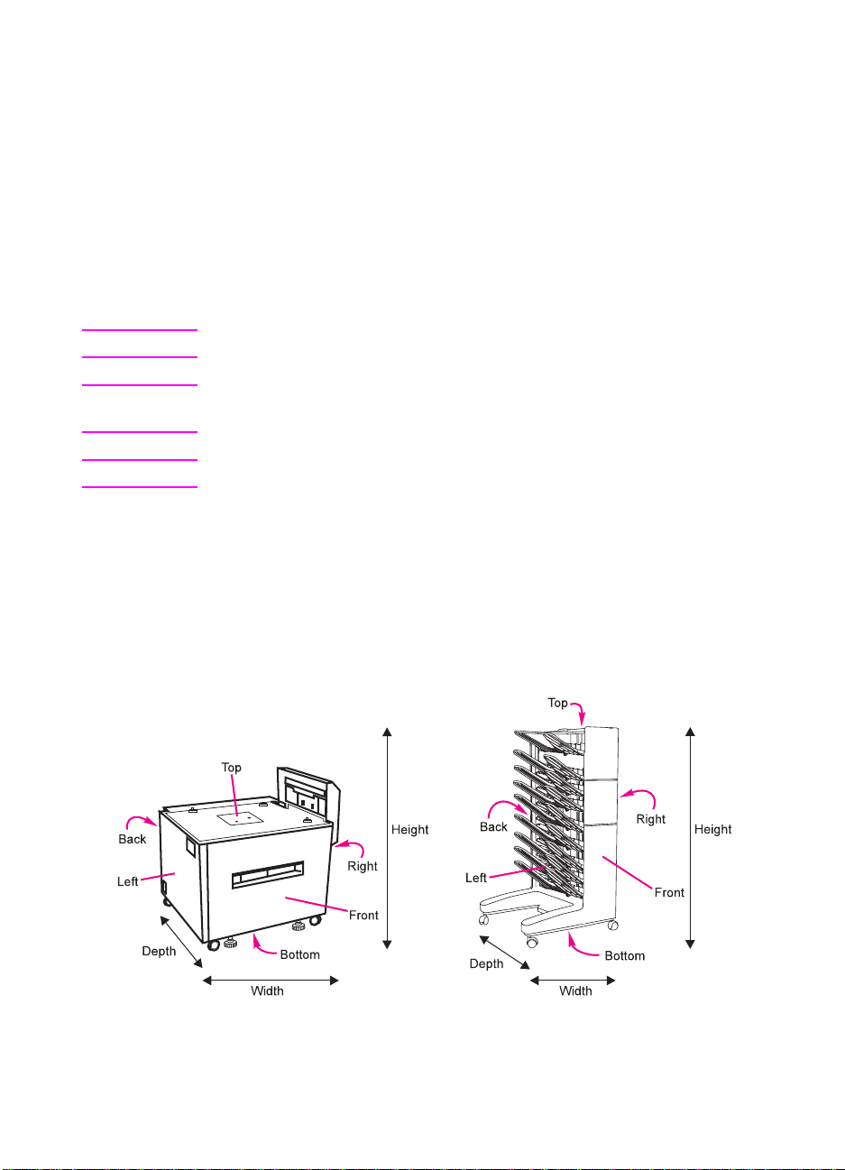
The illustration below shows the orientation of the paper-handling
accessories as they are referred to in this publication.
is used to indicate related documents or emphasis.
C4214-91000 iii
Page 6

Chapter Descriptions
1 Product Information
Contains printer features and product overview, tray capacities and
sizes, media specifications, service approach, how to get technical
assistance, and required safety and compliance statements.
2 Site Requirements
Contains space and environmental requirements.
3 Operating Overview
Contains details about control panel menus, restoring factory
defaults, and resetting and testing the printer.
4 Maintenance and Adjustments
Contains cleaning and preventive maintenance information, and
adjustment procedures for all paper trays.
5 Functional Overview
Contains block diagrams and basic theory of operation for the printer
systems, paper paths, and paper handling devices. Contains basic
cabling information.
6 Removal and Replacement
Contains step-by-step procedures for replacing field replaceab le units
(FRUs) in the printer and paper-handling devices.
7 Troubleshooting
Contains a preliminary troubleshooting table, a table with descriptions
and recommended actions for all control panel messages, image
defect samples, paper handling problems, and troubleshooting
checks and tools.
iv C4214-91000
Page 7

8 Parts and Diagrams
Contains exploded view drawings and part number listings for all
replaceable parts in the printer and paper-handling devices.
Contains two replaceable parts tables: one sorted alphabetically by
part name, and one sorted numerically by part number. Both tables
are cross referenced to the diagrams in the chapter.
Subject Index
Contains an alphabetical, cross referenced listing of information f ound
in the main body of the manual.
C4214-91000 v
Page 8

vi C4214-91000
Page 9

Table of Contents
1 Product Information
Printer Features. . . . . . . . . . . . . . . . . . . . . . . . . . . . . . . . . . . . . . . .2
Paper Capacities and Sizes . . . . . . . . . . . . . . . . . . . . . . . . . . . . . .4
Identification . . . . . . . . . . . . . . . . . . . . . . . . . . . . . . . . . . . . . . . . . .6
Model and Serial Numbers . . . . . . . . . . . . . . . . . . . . . . . . . . . .6
Specifications . . . . . . . . . . . . . . . . . . . . . . . . . . . . . . . . . . . . . . . . .7
Media Selection Guidelines. . . . . . . . . . . . . . . . . . . . . . . . . . . . . .11
Paper . . . . . . . . . . . . . . . . . . . . . . . . . . . . . . . . . . . . . . . . . . .11
Envelopes. . . . . . . . . . . . . . . . . . . . . . . . . . . . . . . . . . . . . . . .11
Adhesive Labels . . . . . . . . . . . . . . . . . . . . . . . . . . . . . . . . . . .12
Transparencies. . . . . . . . . . . . . . . . . . . . . . . . . . . . . . . . . . . .13
Storing Print Media . . . . . . . . . . . . . . . . . . . . . . . . . . . . . . . . .13
Shipping Print Media. . . . . . . . . . . . . . . . . . . . . . . . . . . . . . . .13
Product Overview . . . . . . . . . . . . . . . . . . . . . . . . . . . . . . . . . . . . .14
External View of HP LaserJet 8100/N/DN Engine . . . . . . . . .14
Formatter Assemblies. . . . . . . . . . . . . . . . . . . . . . . . . . . . . . .16
Paper-handling Devices, Accessories, and Options . . . . . . . . . . .17
Ordering Information. . . . . . . . . . . . . . . . . . . . . . . . . . . . . . . .18
Hard Disk . . . . . . . . . . . . . . . . . . . . . . . . . . . . . . . . . . . . . . . .24
Determining Memory Requirements. . . . . . . . . . . . . . . . . . . .24
Service Approach . . . . . . . . . . . . . . . . . . . . . . . . . . . . . . . . . . . . .26
Ordering Parts. . . . . . . . . . . . . . . . . . . . . . . . . . . . . . . . . . . . .26
Exchange Program. . . . . . . . . . . . . . . . . . . . . . . . . . . . . . . . .27
Consumables . . . . . . . . . . . . . . . . . . . . . . . . . . . . . . . . . . . . .27
Toner Cartridge Life . . . . . . . . . . . . . . . . . . . . . . . . . . . . . . . .27
Refilled Toner Cartridges and Non-HP Staple Cartridges . . .28
Recycling Toner Cartridges . . . . . . . . . . . . . . . . . . . . . . . . . .28
Technical Assistance. . . . . . . . . . . . . . . . . . . . . . . . . . . . . . . . . . .29
HP FIRST (Fax Information Retrieval Support Technology). .29
Internet . . . . . . . . . . . . . . . . . . . . . . . . . . . . . . . . . . . . . . . . . .30
World Wide Web. . . . . . . . . . . . . . . . . . . . . . . . . . . . . . . . . . .30
HP Reseller Sales and Service Support Line (US Only). . . . .30
Other Areas. . . . . . . . . . . . . . . . . . . . . . . . . . . . . . . . . . . . . . .30
Warranty . . . . . . . . . . . . . . . . . . . . . . . . . . . . . . . . . . . . . . . . . . . .31
Regulatory Information . . . . . . . . . . . . . . . . . . . . . . . . . . . . . . . . .33
FCC Regulations. . . . . . . . . . . . . . . . . . . . . . . . . . . . . . . . . . .33
Environmental Product Stewardship. . . . . . . . . . . . . . . . . . . .34
Material Safety Data Sheet. . . . . . . . . . . . . . . . . . . . . . . . . . .36
Environmental Conformity. . . . . . . . . . . . . . . . . . . . . . . . . . . .37
Safety Statements. . . . . . . . . . . . . . . . . . . . . . . . . . . . . . . . . .39
C4214-91000 vii
Page 10

2 Site Requirements
Operating Environment . . . . . . . . . . . . . . . . . . . . . . . . . . . . . . . . .44
Space Requirements. . . . . . . . . . . . . . . . . . . . . . . . . . . . . . . . . . .45
Environmental Requirements . . . . . . . . . . . . . . . . . . . . . . . . . . . .47
3 Operating Overview
Using the Control Panel . . . . . . . . . . . . . . . . . . . . . . . . . . . . . . . .50
Control Panel Layout . . . . . . . . . . . . . . . . . . . . . . . . . . . . . . .50
Indicator Lights . . . . . . . . . . . . . . . . . . . . . . . . . . . . . . . . . . . .51
Settings and Defaults . . . . . . . . . . . . . . . . . . . . . . . . . . . . . . .52
Printer Driver Information . . . . . . . . . . . . . . . . . . . . . . . . . . . .52
Paper Source Default . . . . . . . . . . . . . . . . . . . . . . . . . . . . . . .53
Performing a Cold Reset. . . . . . . . . . . . . . . . . . . . . . . . . . . . . . . .54
Setting the Display Language. . . . . . . . . . . . . . . . . . . . . . . . .54
Control Panel Menus. . . . . . . . . . . . . . . . . . . . . . . . . . . . . . . . . . .57
Quick Copy Jobs Menu. . . . . . . . . . . . . . . . . . . . . . . . . . . . . .58
Private/Stored Jobs Menu. . . . . . . . . . . . . . . . . . . . . . . . . . . .58
Information Menu . . . . . . . . . . . . . . . . . . . . . . . . . . . . . . . . . .59
Paper Handling Menu. . . . . . . . . . . . . . . . . . . . . . . . . . . . . . .60
Print Quality Menu . . . . . . . . . . . . . . . . . . . . . . . . . . . . . . . . .62
Printing Menu . . . . . . . . . . . . . . . . . . . . . . . . . . . . . . . . . . . . .64
Configuration Menu. . . . . . . . . . . . . . . . . . . . . . . . . . . . . . . . .67
I/O Menu. . . . . . . . . . . . . . . . . . . . . . . . . . . . . . . . . . . . . . . . .72
EIO Menu . . . . . . . . . . . . . . . . . . . . . . . . . . . . . . . . . . . . . . . .74
Resets Menu. . . . . . . . . . . . . . . . . . . . . . . . . . . . . . . . . . . . . .76
Service Mode . . . . . . . . . . . . . . . . . . . . . . . . . . . . . . . . . . . . . . . .77
Setting Page Count, Maintenance Count,
and Serial Number . . . . . . . . . . . . . . . . . . . . . . . . . . . . . .79
Setting the Cold Reset Default Paper Size. . . . . . . . . . . . . . .80
Testing the Printer. . . . . . . . . . . . . . . . . . . . . . . . . . . . . . . . . . . . .81
Paper Path Test . . . . . . . . . . . . . . . . . . . . . . . . . . . . . . . . . . .81
Configuration Page. . . . . . . . . . . . . . . . . . . . . . . . . . . . . . . . .81
4 Maintenance and Adjustments
Cleaning the Printer and Accessories. . . . . . . . . . . . . . . . . . . . . .86
Cleaning the Printer. . . . . . . . . . . . . . . . . . . . . . . . . . . . . . . .87
Cleaning Spilled Toner . . . . . . . . . . . . . . . . . . . . . . . . . . . . . .88
Preventive Maintenance . . . . . . . . . . . . . . . . . . . . . . . . . . . . . . . .89
Tray Adjustment Procedure. . . . . . . . . . . . . . . . . . . . . . . . . . . . . .90
2000-sheet Input Tray Adjustment Procedure. . . . . . . . . . . . . . . .92
viii C4214-91000
Page 11

5 Functional Overview
Printer Functional Block Diagram . . . . . . . . . . . . . . . . . . . . . . . . .96
Power Distribution System . . . . . . . . . . . . . . . . . . . . . . . . . . . . . .97
AC Power Distribution. . . . . . . . . . . . . . . . . . . . . . . . . . . . . . .98
Overcurrent/Overvoltage Protection . . . . . . . . . . . . . . . . . . . .98
High Voltage Power Distribution. . . . . . . . . . . . . . . . . . . . . . .99
Formatter System . . . . . . . . . . . . . . . . . . . . . . . . . . . . . . . . . . . .100
DC Controller System . . . . . . . . . . . . . . . . . . . . . . . . . . . . . . . . .103
Laser and Scanner Drive . . . . . . . . . . . . . . . . . . . . . . . . . . .103
Paper Motion Monitoring and Control. . . . . . . . . . . . . . . . . .103
Clutches . . . . . . . . . . . . . . . . . . . . . . . . . . . . . . . . . . . . . . . .103
Engine Test Microswitch. . . . . . . . . . . . . . . . . . . . . . . . . . . .104
Motors. . . . . . . . . . . . . . . . . . . . . . . . . . . . . . . . . . . . . . . . . .104
Image Formation System . . . . . . . . . . . . . . . . . . . . . . . . . . . . . .105
Toner Cartridge. . . . . . . . . . . . . . . . . . . . . . . . . . . . . . . . . . .106
Drum Cleaning . . . . . . . . . . . . . . . . . . . . . . . . . . . . . . . . . . .108
Drum Conditioning . . . . . . . . . . . . . . . . . . . . . . . . . . . . . . . .109
Image Writing . . . . . . . . . . . . . . . . . . . . . . . . . . . . . . . . . . . .110
Image Developing. . . . . . . . . . . . . . . . . . . . . . . . . . . . . . . . .112
Image Transferring and Media Separation . . . . . . . . . . . . . .114
Image Fusing . . . . . . . . . . . . . . . . . . . . . . . . . . . . . . . . . . . .115
Paper Paths and Components . . . . . . . . . . . . . . . . . . . . . . . . . .116
Printer, Duplexer, and Envelope Feeder. . . . . . . . . . . . . . . .116
Paper Size Switches (Trays 2 and 3) . . . . . . . . . . . . . . . . . .119
Printing from Tray 1 . . . . . . . . . . . . . . . . . . . . . . . . . . . . . . .119
Printing from Trays 2 and 3. . . . . . . . . . . . . . . . . . . . . . . . . .119
Printing from the Envelope Feeder. . . . . . . . . . . . . . . . . . . .120
Printing with the Duplexer. . . . . . . . . . . . . . . . . . . . . . . . . . .120
2000-sheet Input Tray (Tray 4) Components . . . . . . . . . . . .121
2000-Sheet Input Tray Operation . . . . . . . . . . . . . . . . . . . . .123
2 x 500-sheet Input Tray. . . . . . . . . . . . . . . . . . . . . . . . . . . .126
2 x 500-sheet Input Tray Operation . . . . . . . . . . . . . . . . . . .128
7-bin Tabletop Mailbox Components . . . . . . . . . . . . . . . . . .130
7-bin Tabletop Mailbox Operation. . . . . . . . . . . . . . . . . . . . .132
8-bin Mailbox Components. . . . . . . . . . . . . . . . . . . . . . . . . .136
8-bin Mailbox Operation . . . . . . . . . . . . . . . . . . . . . . . . . . . .139
Finisher Components . . . . . . . . . . . . . . . . . . . . . . . . . . . . . .141
Stapler Unit Operation . . . . . . . . . . . . . . . . . . . . . . . . . . . . .143
Main Functional Cycles of the Stapler (Internal Paper Path)145
Communication Link (Daisy Chain). . . . . . . . . . . . . . . . . . . .146
Paper Jam Detection. . . . . . . . . . . . . . . . . . . . . . . . . . . . . . . . . .148
Printer Timing . . . . . . . . . . . . . . . . . . . . . . . . . . . . . . . . . . . . . . .148
IEEE 1284 Parallel Cable Information. . . . . . . . . . . . . . . . . . . . .150
C4214-91000 Table of Contents ix
Page 12

6 Removal and Replacement
Removal and Replacement Strategy. . . . . . . . . . . . . . . . . . . . . .152
Required Tools . . . . . . . . . . . . . . . . . . . . . . . . . . . . . . . . . . . . . .153
User Installable Accessories. . . . . . . . . . . . . . . . . . . . . . . . . . . .154
Memory and Personality Upgrade . . . . . . . . . . . . . . . . . . . .154
Duplexer . . . . . . . . . . . . . . . . . . . . . . . . . . . . . . . . . . . . . . . .156
Envelope Feeder. . . . . . . . . . . . . . . . . . . . . . . . . . . . . . . . . .156
2000-sheet or 2 x 500-sheet Input Tray . . . . . . . . . . . . . . . .157
8-bin Mailbox/5-bin Mailbox with Stapler . . . . . . . . . . . . . . .158
7-bin Tabletop Mailbox . . . . . . . . . . . . . . . . . . . . . . . . . . . . .159
Hardware Table. . . . . . . . . . . . . . . . . . . . . . . . . . . . . . . . . . . . . .162
Engine Removal and Replacement. . . . . . . . . . . . . . . . . . . . . . .164
Control Panel . . . . . . . . . . . . . . . . . . . . . . . . . . . . . . . . . . . .165
Covers. . . . . . . . . . . . . . . . . . . . . . . . . . . . . . . . . . . . . . . . . .167
Delivery Unit (for Face-down Bin). . . . . . . . . . . . . . . . . . . . .176
Diverter Assembly. . . . . . . . . . . . . . . . . . . . . . . . . . . . . . . . .179
Diverter Door Assembly . . . . . . . . . . . . . . . . . . . . . . . . . . . .180
Lower Right Door Assembly . . . . . . . . . . . . . . . . . . . . . . . . .181
Fan 1, Laser/Scanner and Housing (Exhaust) . . . . . . . . . . .184
Fan 2, Low Voltage Power Supply (Exhaust) . . . . . . . . . . . .186
Fan 3, Formatter Fan and Housing (Intake) . . . . . . . . . . . . .187
Fan 4, Delivery Unit (Exhaust) . . . . . . . . . . . . . . . . . . . . . . .188
Fan 5, Tray 1 (Intake) . . . . . . . . . . . . . . . . . . . . . . . . . . . . . .189
Tray 1 . . . . . . . . . . . . . . . . . . . . . . . . . . . . . . . . . . . . . . . . . .191
Tray 1 Pickup Assembly . . . . . . . . . . . . . . . . . . . . . . . . . . . .194
Feeder Assembly . . . . . . . . . . . . . . . . . . . . . . . . . . . . . . . . .198
Formatter Assembly . . . . . . . . . . . . . . . . . . . . . . . . . . . . . . .200
Fusing Assembly. . . . . . . . . . . . . . . . . . . . . . . . . . . . . . . . . .202
Laser/Scanner Assembly . . . . . . . . . . . . . . . . . . . . . . . . . . .204
Main Gear Assembly. . . . . . . . . . . . . . . . . . . . . . . . . . . . . . .206
Main Motor Assembly . . . . . . . . . . . . . . . . . . . . . . . . . . . . . .209
Paper Input Unit (PIU). . . . . . . . . . . . . . . . . . . . . . . . . . . . . .210
PCA, DC Controller. . . . . . . . . . . . . . . . . . . . . . . . . . . . . . . .211
Output Paper Sensor PCA . . . . . . . . . . . . . . . . . . . . . . . . . .212
High Voltage Power Supply (HVPS). . . . . . . . . . . . . . . . . . .219
Low Voltage Power Supply (LVPS) . . . . . . . . . . . . . . . . . . .220
Registration Assembly . . . . . . . . . . . . . . . . . . . . . . . . . . . . .221
Tray 1 Feed Roller and Separation Pad . . . . . . . . . . . . . . . .224
Tray 2 and 3 Pickup, Feed, and Separation Rollers. . . . . . .226
Paper Input Unit Sensor (PS2) . . . . . . . . . . . . . . . . . . . . . . .227
Registration Sensor (PS1) . . . . . . . . . . . . . . . . . . . . . . . . . .229
Face-up Solenoid Assembly (SL3) . . . . . . . . . . . . . . . . . . . .231
Transfer Roller Assembly . . . . . . . . . . . . . . . . . . . . . . . . . . .232
Tray 2 and 3 Assemblies . . . . . . . . . . . . . . . . . . . . . . . . . . .234
2000-sheet Input Tray Removal and Replacement. . . . . . . . . . .235
Orientation . . . . . . . . . . . . . . . . . . . . . . . . . . . . . . . . . . . . . .236
x C4214-91000
Page 13

Front Cover. . . . . . . . . . . . . . . . . . . . . . . . . . . . . . . . . . . . . .237
Back Cover . . . . . . . . . . . . . . . . . . . . . . . . . . . . . . . . . . . . . .238
Left Cover . . . . . . . . . . . . . . . . . . . . . . . . . . . . . . . . . . . . . . .239
Right Cover. . . . . . . . . . . . . . . . . . . . . . . . . . . . . . . . . . . . . .240
Main Drive Assembly . . . . . . . . . . . . . . . . . . . . . . . . . . . . . .241
Paper Tray . . . . . . . . . . . . . . . . . . . . . . . . . . . . . . . . . . . . . .243
Main Cable Harness . . . . . . . . . . . . . . . . . . . . . . . . . . . . . . .244
Controller PCA . . . . . . . . . . . . . . . . . . . . . . . . . . . . . . . . . . .246
Front LED PCA Assembly. . . . . . . . . . . . . . . . . . . . . . . . . . .248
Pickup Assembly. . . . . . . . . . . . . . . . . . . . . . . . . . . . . . . . . .250
Power Supply . . . . . . . . . . . . . . . . . . . . . . . . . . . . . . . . . . . .252
Pickup, Feed, and Separation Rollers . . . . . . . . . . . . . . . . .254
Paper Quantity Switch Assembly . . . . . . . . . . . . . . . . . . . . .257
Paper Size Switch Assembly . . . . . . . . . . . . . . . . . . . . . . . .257
Vertical Transfer Unit (VTU) . . . . . . . . . . . . . . . . . . . . . . . . .259
Tension Springs . . . . . . . . . . . . . . . . . . . . . . . . . . . . . . . . . .261
Locating Pins . . . . . . . . . . . . . . . . . . . . . . . . . . . . . . . . . . . .262
Casters and Stabilizing Feet. . . . . . . . . . . . . . . . . . . . . . . . .263
Adjustable Foot. . . . . . . . . . . . . . . . . . . . . . . . . . . . . . . . . . .264
2 x 500-sheet Input Tray Removal and Replacement. . . . . . . . .265
Orientation of the 2 x 500-sheet Input Tray . . . . . . . . . . . . .266
Back Cover . . . . . . . . . . . . . . . . . . . . . . . . . . . . . . . . . . . . . .267
Left Cover . . . . . . . . . . . . . . . . . . . . . . . . . . . . . . . . . . . . . . .268
Vertical Transfer Unit (VTU) . . . . . . . . . . . . . . . . . . . . . . . . .269
Right Cover. . . . . . . . . . . . . . . . . . . . . . . . . . . . . . . . . . . . . .272
Front Top Cover . . . . . . . . . . . . . . . . . . . . . . . . . . . . . . . . . .275
Trays 4 and 5 . . . . . . . . . . . . . . . . . . . . . . . . . . . . . . . . . . . .278
Pickup Assembly. . . . . . . . . . . . . . . . . . . . . . . . . . . . . . . . . .280
Paper Deck Drive Assembly. . . . . . . . . . . . . . . . . . . . . . . . .282
Pickup, Feed, and Separation Rollers . . . . . . . . . . . . . . . . .284
Controller PCA . . . . . . . . . . . . . . . . . . . . . . . . . . . . . . . . . . .285
Tray-Size Sensing PCA . . . . . . . . . . . . . . . . . . . . . . . . . . . .286
Power Supply . . . . . . . . . . . . . . . . . . . . . . . . . . . . . . . . . . . .288
Main Cable . . . . . . . . . . . . . . . . . . . . . . . . . . . . . . . . . . . . . .289
Storage Paper Tray. . . . . . . . . . . . . . . . . . . . . . . . . . . . . . . .291
Front Door (Storage Area) . . . . . . . . . . . . . . . . . . . . . . . . . .292
Casters . . . . . . . . . . . . . . . . . . . . . . . . . . . . . . . . . . . . . . . . .293
Foot Tip and Adjustable Foot Tip (Stabilizing Feet) . . . . . . .294
Locating Pins . . . . . . . . . . . . . . . . . . . . . . . . . . . . . . . . . . . .295
Front LED PCA. . . . . . . . . . . . . . . . . . . . . . . . . . . . . . . . . . .296
7-bin Tabletop Mailbox Removal and Replacement . . . . . . . . . .297
Orientation of the 7-bin Tabletop Mailbox. . . . . . . . . . . . . . .298
Front Cover. . . . . . . . . . . . . . . . . . . . . . . . . . . . . . . . . . . . . .299
Back Cover . . . . . . . . . . . . . . . . . . . . . . . . . . . . . . . . . . . . . .302
Top Cover. . . . . . . . . . . . . . . . . . . . . . . . . . . . . . . . . . . . . . .304
Controller PCA . . . . . . . . . . . . . . . . . . . . . . . . . . . . . . . . . . .308
Power Supply . . . . . . . . . . . . . . . . . . . . . . . . . . . . . . . . . . . .309
C4214-91000 Table of Contents xi
Page 14

Right Door Assembly (Paper Path Cover) . . . . . . . . . . . . . .310
Face-down Bins . . . . . . . . . . . . . . . . . . . . . . . . . . . . . . . . . .314
Empty Bin Sensor PCA. . . . . . . . . . . . . . . . . . . . . . . . . . . . .317
Full Bin and Interlock Sensor PCA . . . . . . . . . . . . . . . . . . . .319
LED PCA. . . . . . . . . . . . . . . . . . . . . . . . . . . . . . . . . . . . . . . .321
Face-up Sensors PCA . . . . . . . . . . . . . . . . . . . . . . . . . . . . .322
Reversing Mechanism Motor . . . . . . . . . . . . . . . . . . . . . . . .323
Face-up/Diverter Assembly (Flipper) . . . . . . . . . . . . . . . . . .325
Short Tray 7 . . . . . . . . . . . . . . . . . . . . . . . . . . . . . . . . . . . . .328
Solenoid Reversing Mechanism . . . . . . . . . . . . . . . . . . . . . .329
Flipper Solenoid . . . . . . . . . . . . . . . . . . . . . . . . . . . . . . . . . .330
Handle. . . . . . . . . . . . . . . . . . . . . . . . . . . . . . . . . . . . . . . . . .331
Latching Mechanism. . . . . . . . . . . . . . . . . . . . . . . . . . . . . . .332
Cover Latch. . . . . . . . . . . . . . . . . . . . . . . . . . . . . . . . . . . . . .333
8-bin Mailbox Removal and Replacement. . . . . . . . . . . . . . . . . .334
Orientation . . . . . . . . . . . . . . . . . . . . . . . . . . . . . . . . . . . . . .335
Front and Back Covers. . . . . . . . . . . . . . . . . . . . . . . . . . . . .336
Top Cover. . . . . . . . . . . . . . . . . . . . . . . . . . . . . . . . . . . . . . .337
Power Supply . . . . . . . . . . . . . . . . . . . . . . . . . . . . . . . . . . . .338
Paper Bins and Blind Cover . . . . . . . . . . . . . . . . . . . . . . . . .339
Flipper Assembly . . . . . . . . . . . . . . . . . . . . . . . . . . . . . . . . .340
Delivery Head Motor. . . . . . . . . . . . . . . . . . . . . . . . . . . . . . .343
Transport Belt Motor. . . . . . . . . . . . . . . . . . . . . . . . . . . . . . .344
Input Paper Guide. . . . . . . . . . . . . . . . . . . . . . . . . . . . . . . . .346
Metal Tape and Housing Assembly . . . . . . . . . . . . . . . . . . .348
Controller PCA . . . . . . . . . . . . . . . . . . . . . . . . . . . . . . . . . . .350
Anticurl Strings . . . . . . . . . . . . . . . . . . . . . . . . . . . . . . . . . . .352
Delivery Head Assembly. . . . . . . . . . . . . . . . . . . . . . . . . . . .354
Interlock Switch. . . . . . . . . . . . . . . . . . . . . . . . . . . . . . . . . . .359
Diagnostic LED PCA. . . . . . . . . . . . . . . . . . . . . . . . . . . . . . .360
User Status LED PCA. . . . . . . . . . . . . . . . . . . . . . . . . . . . . .362
Adjustable and Fixed Casters. . . . . . . . . . . . . . . . . . . . . . . .364
Attachment Assembly. . . . . . . . . . . . . . . . . . . . . . . . . . . . . .365
Stapler Assembly Removal and Replacement . . . . . . . . . . . . . .366
Mailbox with Stapler, Stapler Removal or Installation. . . . . .367
Back Plate. . . . . . . . . . . . . . . . . . . . . . . . . . . . . . . . . . . . . . .369
Stapler Controller PCA . . . . . . . . . . . . . . . . . . . . . . . . . . . . .371
Top Cover Assembly. . . . . . . . . . . . . . . . . . . . . . . . . . . . . . .374
Stapler Bed Assembly. . . . . . . . . . . . . . . . . . . . . . . . . . . . . .375
Hinges. . . . . . . . . . . . . . . . . . . . . . . . . . . . . . . . . . . . . . . . . .377
xii C4214-91000
Page 15

7 Troubleshooting
Troubleshooting Process. . . . . . . . . . . . . . . . . . . . . . . . . . . . . . .380
Troubleshooting the Printing System . . . . . . . . . . . . . . . . . . . . .384
Preliminary Operating Checks . . . . . . . . . . . . . . . . . . . . . . .384
General Troubleshooting Information . . . . . . . . . . . . . . . . . . . . .385
Miscellaneous Problems and Solutions . . . . . . . . . . . . . . . .385
Paper Curl. . . . . . . . . . . . . . . . . . . . . . . . . . . . . . . . . . . . . . .390
Power On . . . . . . . . . . . . . . . . . . . . . . . . . . . . . . . . . . . . . . . . . .391
Engine Test. . . . . . . . . . . . . . . . . . . . . . . . . . . . . . . . . . . . . .394
Display. . . . . . . . . . . . . . . . . . . . . . . . . . . . . . . . . . . . . . . . . . . . .395
Event Log . . . . . . . . . . . . . . . . . . . . . . . . . . . . . . . . . . . . . . .395
General Paper Path Troubleshooting . . . . . . . . . . . . . . . . . . . . .399
Paper Jams. . . . . . . . . . . . . . . . . . . . . . . . . . . . . . . . . . . . . .400
Paper Path Test . . . . . . . . . . . . . . . . . . . . . . . . . . . . . . . . . .402
Printer Messages . . . . . . . . . . . . . . . . . . . . . . . . . . . . . . . . . . . .405
Control Panel Messages and Errors. . . . . . . . . . . . . . . . . . .405
Printer Message Tables . . . . . . . . . . . . . . . . . . . . . . . . . . . .408
Self - Diagnostics on Paper-handling Devices . . . . . . . . . . . . . .445
2000-sheet Input Tray Stand-alone Diagnostics. . . . . . . . . .445
2 x 500-sheet Input Tray Standalone Diagnostics . . . . . . . .449
7-bin Tabletop Mailbox Standalone Diagnostics. . . . . . . . . .453
8-bin Mailbox Stand-alone Diagnostics. . . . . . . . . . . . . . . . .458
Information Pages. . . . . . . . . . . . . . . . . . . . . . . . . . . . . . . . . . . .466
Menu Map. . . . . . . . . . . . . . . . . . . . . . . . . . . . . . . . . . . . . . .466
Configuration Page. . . . . . . . . . . . . . . . . . . . . . . . . . . . . . . .468
Communication . . . . . . . . . . . . . . . . . . . . . . . . . . . . . . . . . . . . . .473
Interface Troubleshooting. . . . . . . . . . . . . . . . . . . . . . . . . . .473
Image Quality . . . . . . . . . . . . . . . . . . . . . . . . . . . . . . . . . . . . . . .475
Check the Toner Cartridge . . . . . . . . . . . . . . . . . . . . . . . . . .476
Image Quality Tables . . . . . . . . . . . . . . . . . . . . . . . . . . . . . .477
Repetitive Defect Ruler. . . . . . . . . . . . . . . . . . . . . . . . . . . . .490
Image System Troubleshooting . . . . . . . . . . . . . . . . . . . . . .492
High-Voltage Power Supply Check. . . . . . . . . . . . . . . . . . . .493
Network Troubleshooting . . . . . . . . . . . . . . . . . . . . . . . . . . . . . .495
Verify Host System Operation. . . . . . . . . . . . . . . . . . . . . . . .497
Verify Network and Server Operation. . . . . . . . . . . . . . . . . .497
Diagrams. . . . . . . . . . . . . . . . . . . . . . . . . . . . . . . . . . . . . . . . . . .498
8 Parts and Diagrams
How to Use the Part Lists and Diagrams . . . . . . . . . . . . . . . . . .512
Ordering Parts. . . . . . . . . . . . . . . . . . . . . . . . . . . . . . . . . . . .512
Accessories and Supplies. . . . . . . . . . . . . . . . . . . . . . . . . . . . . .513
Common Hardware. . . . . . . . . . . . . . . . . . . . . . . . . . . . . . . .513
Illustrations and Parts Lists . . . . . . . . . . . . . . . . . . . . . . . . . . . . .513
Alphabetical Parts List. . . . . . . . . . . . . . . . . . . . . . . . . . . . . . . . .549
Numerical Parts List . . . . . . . . . . . . . . . . . . . . . . . . . . . . . . . . . .559
C4214-91000 Table of Contents xiii
Page 16

xiv C4214-91000
Page 17

List of Figures
Figure 1-1 Sample Model and Serial Number Label for the Printer - - - - - - 6
Figure 1-2 Dimensions of Paper Handling Devices - - - - - - - - - - - - - - 8
Figure 1-3 HP LaserJet 8100/N/DN Engine - Front and Right
Side View with Tray 1 Open- - - - - - - - - - - - - - - - - - - 14
Figure 1-4 Rear and Left Side View - - - - - - - - - - - - - - - - - - - - 16
Figure 1-5 HP LaserJet 8100/N/DN Optional Paper Handling Devices- - - - 17
Figure 1-6 Sample 4% Page Coverage- - - - - - - - - - - - - - - - - - - 27
Figure 2-1 Printer Space Requirements (Top view) - - - - - - - - - - - - - 45
Figure 2-2 Printer Space Requirements (Side view)- - - - - - - - - - - - - 45
Figure 2-3 Printer Space Requirements (with Mailbox and Input Device) - - 46
Figure 3-1 Control Panel Layout - - - - - - - - - - - - - - - - - - - - - - 50
Figure 3-2 Configuration Page (varies with installed options) - - - - - - - - 82
Figure 3-3 Menu Map Page (varies with installed options)- - - - - - - - - - 83
Figure 4-1 Image Area Margins - - - - - - - - - - - - - - - - - - - - - - 90
Figure 4-2 Tray Position Adjustment - - - - - - - - - - - - - - - - - - - - 91
Figure 4-3 Tray 4 Position Adjustment - - - - - - - - - - - - - - - - - - - 92
Figure 5-1 Printer Functional Block Diagram - - - - - - - - - - - - - - - - 96
Figure 5-2 Low Voltage Power Distribution System - - - - - - - - - - - - - 97
Figure 5-3 Low Voltage Power Supply - - - - - - - - - - - - - - - - - - - 98
Figure 5-4 High Voltage Power Supply Contacts - - - - - - - - - - - - - - 99
Figure 5-5 Normal Mode vs EconoMode - - - - - - - - - - - - - - - - - - 102
Figure 5-6 Image Formation Block Diagram - - - - - - - - - - - - - - - - 105
Figure 5-7 Photosensitive Drum - - - - - - - - - - - - - - - - - - - - - - 107
Figure 5-8 Drum Cleaning - - - - - - - - - - - - - - - - - - - - - - - - - 108
Figure 5-9 Primary Charging Roller- - - - - - - - - - - - - - - - - - - - - 109
Figure 5-10 Image Writing- - - - - - - - - - - - - - - - - - - - - - - - - - 110
Figure 5-11 Image Development - - - - - - - - - - - - - - - - - - - - - - 113
Figure 5-12 Image Transferring and Media Separation- - - - - - - - - - - - 114
Figure 5-13 Image Fusing- - - - - - - - - - - - - - - - - - - - - - - - - - 115
Figure 5-14 Printer Paper Paths- - - - - - - - - - - - - - - - - - - - - - - 116
Figure 5-15 Printer Sensors, Solenoids, Clutches, Motors, and Fans - - - - - 118
Figure 5-16 2000-sheet Input Tray Paper Path- - - - - - - - - - - - - - - - 121
Figure 5-17 2000-sheet Input Tray Sensors, Switches, Clutches, and Motors- 123
Figure 5-18 2 x 500-sheet Input Tray Paper Path - - - - - - - - - - - - - - 126
Figure 5-19 2 x 500-sheet input Tray Sensors and Switches - - - - - - - - - 127
Figure 5-20 7-bin Tabletop Mailbox Components (1 of 2)- - - - - - - - - - - 130
Figure 5-21 7-bin Tabletop Mailbox Components (2 of 2)- - - - - - - - - - - 131
Figure 5-22 7-bin Tabletop Mailbox Block Diagram- - - - - - - - - - - - - - 135
Figure 5-23 8-bin Mailbox Paper Path - - - - - - - - - - - - - - - - - - - - 136
Figure 5-24 8-bin Mailbox Sensors, Switches, Motors, and Controller PCA - - 138
Figure 5-25 Finisher Paper Path- - - - - - - - - - - - - - - - - - - - - - - 142
C4214-91000 xv
Page 18

Figure 5-26 Stapler Motors, Sensors, and Switches - - - - - - - - - - - - - 142
Figure 5-27 Stapler Cycles - - - - - - - - - - - - - - - - - - - - - - - - - 145
Figure 5-28 Recommended C-link Configuration (Daisy Chain)- - - - - - - - 147
Figure 5-29 General Timing Diagram - - - - - - - - - - - - - - - - - - - - 149
Figure 5-30 Parallel Cable Pin Assignments (C2946A)- - - - - - - - - - - - 150
Figure 6-1 Phillips vs. Posidriv Screwdrivers - - - - - - - - - - - - - - - - 153
Figure 6-2 Disk Drive - - - - - - - - - - - - - - - - - - - - - - - - - - - 155
Figure 6-3 Control Panel (1 of 2) - - - - - - - - - - - - - - - - - - - - - - 165
Figure 6-4 Control Panel (2 of 2) - - - - - - - - - - - - - - - - - - - - - - 166
Figure 6-5 AC Access Cover- - - - - - - - - - - - - - - - - - - - - - - - 168
Figure 6-6 Back Cover- - - - - - - - - - - - - - - - - - - - - - - - - - - 169
Figure 6-7 Front Cover (1 of 2)- - - - - - - - - - - - - - - - - - - - - - - 170
Figure 6-8 Front Cover (2 of 2)- - - - - - - - - - - - - - - - - - - - - - - 171
Figure 6-9 Left Lower Cover - - - - - - - - - - - - - - - - - - - - - - - - 172
Figure 6-10 Top Cover (1 of 2) - - - - - - - - - - - - - - - - - - - - - - - 173
Figure 6-11 Top Cover (2 of 2) - - - - - - - - - - - - - - - - - - - - - - - 174
Figure 6-12 Delivery Unit (1 of 2) - - - - - - - - - - - - - - - - - - - - - - 176
Figure 6-13 Delivery Unit (2 of 2) - - - - - - - - - - - - - - - - - - - - - - 177
Figure 6-14 Diverter Assembly - - - - - - - - - - - - - - - - - - - - - - - 179
Figure 6-15 Diverter Door Assembly- - - - - - - - - - - - - - - - - - - - - 180
Figure 6-16 Lower Right Door Assembly (1 of 3)- - - - - - - - - - - - - - - 181
Figure 6-17 Right Lower Door Assembly (2 of 3)- - - - - - - - - - - - - - - 182
Figure 6-18 Right Lower Door Assembly (3 of 3)- - - - - - - - - - - - - - - 183
Figure 6-19 Fan 1, Laser/Scanner (1 of 2) - - - - - - - - - - - - - - - - - - 184
Figure 6-20 Fan 1, Laser/Scanner (2 of 2) - - - - - - - - - - - - - - - - - - 185
Figure 6-21 Fan 2, Low Voltage Power Supply- - - - - - - - - - - - - - - - 186
Figure 6-22 Fan 3, Formatter Fan - - - - - - - - - - - - - - - - - - - - - - 187
Figure 6-23 Fan 4, Delivery Unit- - - - - - - - - - - - - - - - - - - - - - - 188
Figure 6-24 Fan 5 Removal (1 of 2) - - - - - - - - - - - - - - - - - - - - - 189
Figure 6-25 Fan 5 Removal (2 of 2) - - - - - - - - - - - - - - - - - - - - - 190
Figure 6-26 Tray 1 Removal (1 of 3)- - - - - - - - - - - - - - - - - - - - - 191
Figure 6-27 Tray 1 Removal (2 of 3)- - - - - - - - - - - - - - - - - - - - - 192
Figure 6-28 Tray 1 Removal (3 of 3)- - - - - - - - - - - - - - - - - - - - - 193
Figure 6-29 Tray 1 Pickup Unit Removal (1 of 4)- - - - - - - - - - - - - - - 194
Figure 6-30 Tray 1 Pickup Unit Removal (2 of 4)- - - - - - - - - - - - - - - 195
Figure 6-31 Tray 1 Pickup Unit Removal (3 of 4)- - - - - - - - - - - - - - - 196
Figure 6-32 Tray 1 Pickup Unit Removal (4 of 4)- - - - - - - - - - - - - - - 197
Figure 6-33 Feeder Assembly (1 of 2) - - - - - - - - - - - - - - - - - - - - 198
Figure 6-34 Feeder Assembly (2 of 2) - - - - - - - - - - - - - - - - - - - - 199
Figure 6-35 Formatter Assembly - - - - - - - - - - - - - - - - - - - - - - 201
Figure 6-36 Fusing Assembly - - - - - - - - - - - - - - - - - - - - - - - - 202
Figure 6-37 Laser/Scanner Assembly - - - - - - - - - - - - - - - - - - - - 204
Figure 6-38 Main Gear Assembly (1 of 3) - - - - - - - - - - - - - - - - - - 206
Figure 6-39 Main Gear Assembly (2 of 3) - - - - - - - - - - - - - - - - - - 207
Figure 6-40 Main Gear Assembly (3 of 3) - - - - - - - - - - - - - - - - - - 208
Figure 6-41 Main Motor - - - - - - - - - - - - - - - - - - - - - - - - - - - 209
Figure 6-42 Paper Input Unit - - - - - - - - - - - - - - - - - - - - - - - - 210
xvi C4214-91000
Page 19

Figure 6-43 DC Controller PCA - - - - - - - - - - - - - - - - - - - - - - - 211
Figure 6-44 Output Paper Sensor PCA (1 of 4) - - - - - - - - - - - - - - - 212
Figure 6-45 Output Paper Sensor PCA (2 of 4) - - - - - - - - - - - - - - - 213
Figure 6-46 Output Paper Sensor PCA (3 of 4) - - - - - - - - - - - - - - - 214
Figure 6-47 Output Paper Sensor PCA (4 of 4) - - - - - - - - - - - - - - - 215
Figure 6-48 Paper Size PCA (1 of 3)- - - - - - - - - - - - - - - - - - - - - 216
Figure 6-49 Paper Size PCA (2 of 3)- - - - - - - - - - - - - - - - - - - - - 217
Figure 6-50 Paper Size PCA (3 of 3)- - - - - - - - - - - - - - - - - - - - - 218
Figure 6-51 High Voltage Power Supply - - - - - - - - - - - - - - - - - - - 219
Figure 6-52 Low Voltage Power Supply - - - - - - - - - - - - - - - - - - - 220
Figure 6-53 Registration Assembly (1 of 3) - - - - - - - - - - - - - - - - - 221
Figure 6-54 Registration Assembly (2 of 3) - - - - - - - - - - - - - - - - - 222
Figure 6-55 Registration Assembly (3 of 3) - - - - - - - - - - - - - - - - - 223
Figure 6-56 Tray 1 Feed Roller - - - - - - - - - - - - - - - - - - - - - - - 224
Figure 6-57 Tray 1 Separation Pad - - - - - - - - - - - - - - - - - - - - - 225
Figure 6-58 Tray 2 and 3, Pickup, Feed, and Separation Rollers - - - - - - - 226
Figure 6-59 Paper Input Unit Sensor (PS2) - - - - - - - - - - - - - - - - - 228
Figure 6-60 Registration Sensor (PS1) - - - - - - - - - - - - - - - - - - - 230
Figure 6-61 Face-up Solenoid Assembly, SL3 - - - - - - - - - - - - - - - - 231
Figure 6-62 Transfer Roller Assembly - - - - - - - - - - - - - - - - - - - - 232
Figure 6-63 2000-sheet Input Tray Orientation- - - - - - - - - - - - - - - - 236
Figure 6-64 2000-sheet Input Tray Front Cover - - - - - - - - - - - - - - - 237
Figure 6-65 2000-sheet Input Tray Back Cover - - - - - - - - - - - - - - - 238
Figure 6-66 2000-sheet Input Tray Left Cover - - - - - - - - - - - - - - - - 239
Figure 6-67 2000-sheet Input Tray Right Cover - - - - - - - - - - - - - - - 240
Figure 6-68 2000-sheet Input Tray Main Drive Assembly- - - - - - - - - - - 241
Figure 6-69 2000-sheet Input Tray Paper Tray- - - - - - - - - - - - - - - - 243
Figure 6-70 2000-sheet Input Tray Main Cable Harness - - - - - - - - - - - 245
Figure 6-71 2000-sheet Input Tray Controller PCA- - - - - - - - - - - - - - 246
Figure 6-72 2000-sheet Input Tray Front LED PCA - - - - - - - - - - - - - 249
Figure 6-73 2000-sheet Input Tray Pickup Assembly- - - - - - - - - - - - - 250
Figure 6-74 2000-sheet Input Tray Power Supply - - - - - - - - - - - - - - 252
Figure 6-75 2000-sheet Input Tray Rollers: Pickup, Feed, and Separation - - 255
Figure 6-76 2000-sheet Input Tray Paper Size and Paper Quantity Switch - - 258
Figure 6-77 2000-sheet Input Tray Paper Size and Paper Quantity Switch
Assemblies (2 of 2) - - - - - - - - - - - - - - - - - - - - - - - 258
Figure 6-78 2000-sheet Input Tray Vertical Transfer Unit (VTU) - - - - - - - 259
Figure 6-79 2000-sheet Input Tray Tension Springs - - - - - - - - - - - - - 261
Figure 6-80 2000-sheet Input Tray Locating Pins - - - - - - - - - - - - - - 262
Figure 6-81 2000-sheet Input Tray Casters - - - - - - - - - - - - - - - - - 263
Figure 6-82 2000-sheet Input Tray Adjustable Foot - - - - - - - - - - - - - 264
Figure 6-83 Orientation of the 2 x 500-sheet Input Tray - - - - - - - - - - - 266
Figure 6-84 Back Cover- - - - - - - - - - - - - - - - - - - - - - - - - - - 267
Figure 6-85 Left Cover - - - - - - - - - - - - - - - - - - - - - - - - - - - 268
Figure 6-86 Vertical Transfer Unit (VTU) (1 of 3) - - - - - - - - - - - - - - - 269
Figure 6-87 Vertical Transfer Unit (VTU) (2 of 3) - - - - - - - - - - - - - - - 270
Figure 6-88 Vertical Transfer Unit (VTU) (3 of 3) - - - - - - - - - - - - - - - 271
C4214-91000 List of Figures xvii
Page 20

Figure 6-89 Right Cover (1 of 3)- - - - - - - - - - - - - - - - - - - - - - - 272
Figure 6-90 Right Cover (2 of 3)- - - - - - - - - - - - - - - - - - - - - - - 273
Figure 6-91 Right Cover (3 of 3)- - - - - - - - - - - - - - - - - - - - - - - 274
Figure 6-92 Front Top Cover (1 of 3) - - - - - - - - - - - - - - - - - - - - 275
Figure 6-93 Front Top Cover (2 of 3) - - - - - - - - - - - - - - - - - - - - 276
Figure 6-94 Front Top Cover (3 of 3) - - - - - - - - - - - - - - - - - - - - 277
Figure 6-95 Trays 4 and 5 (1 of 2) - - - - - - - - - - - - - - - - - - - - - - 278
Figure 6-96 Trays 4 and 5 (2 of 2) - - - - - - - - - - - - - - - - - - - - - - 279
Figure 6-97 Pickup Assembly (1 of 2) - - - - - - - - - - - - - - - - - - - - 280
Figure 6-98 Pickup Assembly (2 of 2) - - - - - - - - - - - - - - - - - - - - 281
Figure 6-99 Paper Deck Drive Assembly (1 of 2)- - - - - - - - - - - - - - - 282
Figure 6-100 Paper Deck Drive Assembly (2 of 2)- - - - - - - - - - - - - - - 283
Figure 6-101 Pickup, Feed, and Separation Rollers - - - - - - - - - - - - - - 284
Figure 6-102 2 x 500-sheet Input Tray Controller PCA- - - - - - - - - - - - - 285
Figure 6-103 Tray-Size Sensing PCA (1 of 2) - - - - - - - - - - - - - - - - - 286
Figure 6-104 Tray-Size Sensing PCA (2 of 2) - - - - - - - - - - - - - - - - - 287
Figure 6-105 Power Supply- - - - - - - - - - - - - - - - - - - - - - - - - - 288
Figure 6-106 Main Cable (1 of 2) - - - - - - - - - - - - - - - - - - - - - - - 289
Figure 6-107 Main Cable (2 of 2) - - - - - - - - - - - - - - - - - - - - - - - 290
Figure 6-108 Storage Paper Tray - - - - - - - - - - - - - - - - - - - - - - - 291
Figure 6-109 Front Door (Storage Area) - - - - - - - - - - - - - - - - - - - 292
Figure 6-110 Casters- - - - - - - - - - - - - - - - - - - - - - - - - - - - - 293
Figure 6-111 Foot Tip and Adjustable Foot Tip - - - - - - - - - - - - - - - - 294
Figure 6-112 Locating Pins - - - - - - - - - - - - - - - - - - - - - - - - - - 295
Figure 6-113 Front LED PCA - - - - - - - - - - - - - - - - - - - - - - - - - 296
Figure 6-114 Orientation of the 7-bin Tabletop Mailbox - - - - - - - - - - - - 298
Figure 6-115 Front cover (1 of 3) - - - - - - - - - - - - - - - - - - - - - - - 299
Figure 6-116 Front cover (2 of 3) - - - - - - - - - - - - - - - - - - - - - - - 300
Figure 6-117 Front cover (3 of 3) - - - - - - - - - - - - - - - - - - - - - - - 301
Figure 6-118 Back cover (1 of 2) - - - - - - - - - - - - - - - - - - - - - - - 302
Figure 6-119 Back cover (2 of 2) - - - - - - - - - - - - - - - - - - - - - - - 303
Figure 6-120 Top cover (1 of 4)- - - - - - - - - - - - - - - - - - - - - - - - 304
Figure 6-121 Top cover (2 of 4)- - - - - - - - - - - - - - - - - - - - - - - - 305
Figure 6-122 Top cover (3 of 4)- - - - - - - - - - - - - - - - - - - - - - - - 306
Figure 6-123 Top cover (4 of 4)- - - - - - - - - - - - - - - - - - - - - - - - 307
Figure 6-124 Mailbox Controller PCA - - - - - - - - - - - - - - - - - - - - - 308
Figure 6-125 Mailbox Power Supply - - - - - - - - - - - - - - - - - - - - - 309
Figure 6-126 Right Door Assembly (Paper Path Cover) (1 of 5) - - - - - - - - 310
Figure 6-127 Right Door Assembly (Paper Path Cover) (2 of 5) - - - - - - - - 311
Figure 6-128 Right Door Assembly (Paper Path Cover) (3 of 5) - - - - - - - - 311
Figure 6-129 Right Door Assembly (Paper Path Cover) (3 of 5) - - - - - - - - 312
Figure 6-130 Right Door Assembly (Paper Path Cover) (4 of 5) - - - - - - - - 313
Figure 6-131 Face-down Bins (1 of 3)- - - - - - - - - - - - - - - - - - - - - 314
Figure 6-132 Face-down Bins (2 of 3)- - - - - - - - - - - - - - - - - - - - - 315
Figure 6-133 Face-down Bins (3 of 3)- - - - - - - - - - - - - - - - - - - - - 316
Figure 6-134 Empty Bin Sensor PCA (1 of 2) - - - - - - - - - - - - - - - - - 317
Figure 6-135 Empty Bin Sensor PCA (2 of 2) - - - - - - - - - - - - - - - - - 318
xviii C4214-91000
Page 21

Figure 6-136 Full Bin and Interlock Sensor PCA (1 of 2)- - - - - - - - - - - - 319
Figure 6-137 Full Bin and Interlock Sensor PCA (2 of 2)- - - - - - - - - - - - 320
Figure 6-138 LED PCA - - - - - - - - - - - - - - - - - - - - - - - - - - - - 321
Figure 6-139 Face-up Sensors PCA - - - - - - - - - - - - - - - - - - - - - 322
Figure 6-140 Reversing Mechanism Motor (1 of 2) - - - - - - - - - - - - - - 323
Figure 6-141 Reversing Mechanism Motor (2 of 2) - - - - - - - - - - - - - - 324
Figure 6-142 Face-up/Diverter Assembly (Flipper) (1 of 3)- - - - - - - - - - - 325
Figure 6-143 Face-up/Diverter Assembly (Flipper) (2 of 3)- - - - - - - - - - - 326
Figure 6-144 Face-up/Diverter Assembly (Flipper) (3 of 3)- - - - - - - - - - - 327
Figure 6-145 Short Tray 7 - - - - - - - - - - - - - - - - - - - - - - - - - - 328
Figure 6-146 Solenoid Reversing Mechanism - - - - - - - - - - - - - - - - - 329
Figure 6-147 Flipper Solenoid - - - - - - - - - - - - - - - - - - - - - - - - 330
Figure 6-148 7-bin Tabletop Mailbox Handle - - - - - - - - - - - - - - - - - 331
Figure 6-149 Latching Mechanism - - - - - - - - - - - - - - - - - - - - - - 332
Figure 6-150 Cover Latch - - - - - - - - - - - - - - - - - - - - - - - - - - 333
Figure 6-151 Orientation of the 8-bin Mailbox - - - - - - - - - - - - - - - - - 335
Figure 6-152 8-bin Mailbox Covers (Front and Back) - - - - - - - - - - - - - 336
Figure 6-153 8-bin Mailbox Top Cover - - - - - - - - - - - - - - - - - - - - 337
Figure 6-154 8-bin Mailbox Power Supply- - - - - - - - - - - - - - - - - - - 338
Figure 6-155 8-bin Mailbox Paper Bins and Blind Cover - - - - - - - - - - - - 339
Figure 6-156 8-bin Mailbox Flipper Assembly (1 of 3) - - - - - - - - - - - - - 340
Figure 6-157 8-bin Mailbox Flipper Assembly (2 of 3) - - - - - - - - - - - - - 341
Figure 6-158 8-bin Mailbox Flipper Assembly (3 of 3) - - - - - - - - - - - - - 342
Figure 6-159 8-bin Mailbox Delivery Head Motor - - - - - - - - - - - - - - - 343
Figure 6-160 8-bin Mailbox Transport Belt Motor - - - - - - - - - - - - - - - 344
Figure 6-161 8-bin Mailbox Input Paper Guide (1 of 2)- - - - - - - - - - - - - 346
Figure 6-162 8-bin Mailbox Input Paper Guide (2 of 2)- - - - - - - - - - - - - 347
Figure 6-163 8-bin Mailbox Metal Tape and Housing Assembly (1 of 2) - - - - 348
Figure 6-164 8-bin Mailbox Metal Tape and Housing Assembly (2 of 2) - - - - 349
Figure 6-165 8-bin Mailbox Controller PCA (1 of 2) - - - - - - - - - - - - - - 350
Figure 6-166 8-bin Mailbox Controller PCA (2 of 2) - - - - - - - - - - - - - - 351
Figure 6-167 8-bin Mailbox Anticurl Strings (1 of 2) - - - - - - - - - - - - - - 352
Figure 6-168 8-bin Mailbox Anticurl Strings (2 of 2) - - - - - - - - - - - - - - 353
Figure 6-169 8-bin Mailbox Delivery Head Assembly (1 of 4) - - - - - - - - - 354
Figure 6-170 8-bin Mailbox Delivery Head Assembly (2 of 4) - - - - - - - - - 355
Figure 6-171 8-bin Mailbox Delivery Head Assembly (3 of 4) - - - - - - - - - 356
Figure 6-172 8-bin Mailbox Delivery Head Assembly (4 of 4) - - - - - - - - - 357
Figure 6-173 8-bin Mailbox Interlock Switch- - - - - - - - - - - - - - - - - - 359
Figure 6-174 8-bin Mailbox Diagnostic LED PCA (1 of 2) - - - - - - - - - - - 360
Figure 6-175 8-bin Mailbox Diagnostic LED PCA (2 of 2) - - - - - - - - - - - 361
Figure 6-176 8-bin Mailbox User Status LED PCA (1 of 2)- - - - - - - - - - - 362
Figure 6-177 8-bin Mailbox User Status LED PCA (2 of 2)- - - - - - - - - - - 363
Figure 6-178 8-bin Mailbox Adjustable and Fixed Casters - - - - - - - - - - - 364
Figure 6-179 8-bin Mailbox Attachment Assembly- - - - - - - - - - - - - - - 365
Figure 6-180 Mailbox with Stapler, Stapler Removal or Installation- - - - - - - 367
Figure 6-181 C-link Cable on Mailbox with Stapler - - - - - - - - - - - - - - 368
Figure 6-182 Back Plate (1 of 2) - - - - - - - - - - - - - - - - - - - - - - - 369
C4214-91000 List of Figures xix
Page 22

Figure 6-183 Back Plate (2 of 2) - - - - - - - - - - - - - - - - - - - - - - - 370
Figure 6-184 Stapler Controller PCA (1 of 3) - - - - - - - - - - - - - - - - - 371
Figure 6-185 Stapler Controller PCA (2 of 3) - - - - - - - - - - - - - - - - - 372
Figure 6-186 Stapler Controller PCA (3 of 3) - - - - - - - - - - - - - - - - - 373
Figure 6-187 Top Cover Assembly - - - - - - - - - - - - - - - - - - - - - - 374
Figure 6-188 Stapler Bed Assembly - - - - - - - - - - - - - - - - - - - - - 375
Figure 6-189 Hinges - - - - - - - - - - - - - - - - - - - - - - - - - - - - - 377
Figure 7-1 HP LaserJet Troubleshooting Process (1 of 2) - - - - - - - - - 382
Figure 7-2 HP LaserJet Troubleshooting Process (2 of 2) - - - - - - - - - 383
Figure 7-3 Fan Location and Airflow - - - - - - - - - - - - - - - - - - - - 393
Figure 7-4 Engine Test Button - - - - - - - - - - - - - - - - - - - - - - - 394
Figure 7-5 Sample Event Log - - - - - - - - - - - - - - - - - - - - - - - 396
Figure 7-6 Paper Path Jam Locations - - - - - - - - - - - - - - - - - - - 401
Figure 7-7 Paper Path Test Source and Output Selection- - - - - - - - - - 403
Figure 7-8 Error Format for Paper Handling - - - - - - - - - - - - - - - - 407
Figure 7-9 8-bin Mailbox LEDs Description - - - - - - - - - - - - - - - - - 458
Figure 7-10 8-bin Mailbox Power Supply Test Mode Switch - - - - - - - - - 459
Figure 7-11 Sample Menu Map - - - - - - - - - - - - - - - - - - - - - - - 467
Figure 7-12 Sample Configuration Page (1 of 2) - - - - - - - - - - - - - - - 469
Figure 7-13 Sample Configuration Page (2 of 2) - - - - - - - - - - - - - - - 470
Figure 7-14 Communications Link (C-link) Cables, Supported Daisy Chain
Connections - - - - - - - - - - - - - - - - - - - - - - - - - - 473
Figure 7-15 Repetitive Defect Ruler - - - - - - - - - - - - - - - - - - - - - 491
Figure 7-16 High Voltage Power Supply Contacts - - - - - - - - - - - - - - 494
Figure 7-17 Sample JetDirect Configuration Page - - - - - - - - - - - - - - 496
Figure 7-18 Printer Sensors and Switches - - - - - - - - - - - - - - - - - - 499
Figure 7-19 Printer Motor, Clutches, and Solenoids - - - - - - - - - - - - - 500
Figure 7-20 DC Controller Inputs and Outputs (1 of 5) - - - - - - - - - - - - 501
Figure 7-21 DC Controller Inputs and Outputs (2 of 5) - - - - - - - - - - - - 502
Figure 7-22 DC Controller Inputs and Outputs (3 of 5) - - - - - - - - - - - - 503
Figure 7-23 DC Controller Inputs and Outputs (4 of 5) - - - - - - - - - - - - 504
Figure 7-24 DC Controller Inputs and Outputs (5 of 5) - - - - - - - - - - - - 505
Figure 7-25 Mailbox with Stapler Wiring Diagram - - - - - - - - - - - - - - 506
Figure 7-26 2000-sheet Input Tray Controller PCA Inputs - - - - - - - - - - 507
Figure 7-27 2000-sheet Input Tray Controller PCA Outputs - - - - - - - - - 508
Figure 7-28 2000-sheet Input Tray Main Wiring Diagram- - - - - - - - - - - 509
Figure 7-29 8-bin Mailbox Main Wiring Diagram - - - - - - - - - - - - - - - 510
Figure 8-1 HP LaserJet 8100/8100N/8100DN Printer and Paper-Handling
Components - - - - - - - - - - - - - - - - - - - - - - - - - - 514
Figure 8-2 Printer Covers and Doors - - - - - - - - - - - - - - - - - - - - 518
Figure 8-3 Printer Internal Components (1 of 4)- - - - - - - - - - - - - - - 520
Figure 8-4 Printer Internal Components (2 of 4)- - - - - - - - - - - - - - - 522
Figure 8-5 Printer Internal Components (3 of 4)- - - - - - - - - - - - - - - 524
Figure 8-6 Printer Internal Components (4 of 4)- - - - - - - - - - - - - - - 526
Figure 8-7 Detail of Assemblies - - - - - - - - - - - - - - - - - - - - - - 528
Figure 8-8 PCB Assembly Location Diagram - - - - - - - - - - - - - - - - 530
Figure 8-9 Face-up Solenoid Assembly- - - - - - - - - - - - - - - - - - - 531
xx C4214-91000
Page 23

Figure 8-10 2000-sheet Input Tray Components (1 of 2) - - - - - - - - - - - 532
Figure 8-11 2000-sheet Input Tray Components (2 of 2) - - - - - - - - - - - 534
Figure 8-12 8-bin Mailbox Components (1 of 3) - - - - - - - - - - - - - - - 536
Figure 8-13 8-bin Mailbox Components (2 of 3) - - - - - - - - - - - - - - - 538
Figure 8-14 8-bin Mailbox Components (3 of 3) - - - - - - - - - - - - - - - 540
Figure 8-15 Stapler Internal Components - - - - - - - - - - - - - - - - - - 542
Figure 8-16 2 x 500-sheet Input Tray Internal Components- - - - - - - - - - 545
Figure 8-17 7-bin Tabletop Mailbox Internal Components - - - - - - - - - - 547
C4214-91000 List of Figures xxi
Page 24

xxii C4214-91000
Page 25

List of Tables
Table 1-1. Common features of the HP LaserJet 8100, HP LaserJet 8100 N,
and HP LaserJet 8100 DN - - - - - - - - - - - - - - - - - - - - 2
Table 1-2. Comparison of Printer Features - - - - - - - - - - - - - - - - - - 3
Table 1-3. Paper Capacities and Sizes - - - - - - - - - - - - - - - - - - - - 4
Table 1-4. Dimensions of Printer and Paper-handling Devices - - - - - - - - 7
Table 1-5. Dimensions of Output Devices - - - - - - - - - - - - - - - - - - 8
Table 1-6. Electrical Specifications - - - - - - - - - - - - - - - - - - - - - - 9
Table 1-7. Acoustic Emissions - - - - - - - - - - - - - - - - - - - - - - - 10
Table 1-8. Accessories and Options - - - - - - - - - - - - - - - - - - - - 18
Table 1-9. Minimum Memory Requirements - - - - - - - - - - - - - - - - 25
Table 2-1. Printer and Toner Cartridge Environmental Conditions - - - - - - 47
Table 3-1. Control Panel Keys - - - - - - - - - - - - - - - - - - - - - - - 50
Table 3-2. Indicator Lights - - - - - - - - - - - - - - - - - - - - - - - - - 51
Table 3-3. Factory Default Settings- - - - - - - - - - - - - - - - - - - - - 55
Table 3-4. Information Menu - - - - - - - - - - - - - - - - - - - - - - - - 58
Table 3-5. Information Menu - - - - - - - - - - - - - - - - - - - - - - - - 58
Table 3-6. Information Menu - - - - - - - - - - - - - - - - - - - - - - - - 59
Table 3-7. Paper Handling Menu- - - - - - - - - - - - - - - - - - - - - - 60
Table 3-8. Print Quality Menu - - - - - - - - - - - - - - - - - - - - - - - 62
Table 3-9. Printing Menu- - - - - - - - - - - - - - - - - - - - - - - - - - 64
Table 3-10. Configuration Menu - - - - - - - - - - - - - - - - - - - - - - - 67
Table 3-11. I/O Menu - - - - - - - - - - - - - - - - - - - - - - - - - - - - 72
Table 3-12. EIO Menu - - - - - - - - - - - - - - - - - - - - - - - - - - - 74
Table 3-13. Resets Menu - - - - - - - - - - - - - - - - - - - - - - - - - - 76
Table 3-14. Service Mode Menu Items - - - - - - - - - - - - - - - - - - - 77
Table 3-15. Key to Figure 3-2 - - - - - - - - - - - - - - - - - - - - - - - - 82
Table 3-16. Key to Figure 3-3 - - - - - - - - - - - - - - - - - - - - - - - - 83
Table 4-1. Cleaning the Printer- - - - - - - - - - - - - - - - - - - - - - - 88
Table 5-1. Printer Sensors, Solenoids, Clutches, Motors, and Fans - - - - - 117
Table 5-2. Paper Size Switches - - - - - - - - - - - - - - - - - - - - - - 119
Table 5-3. 2000-sheet Input Tray Sensors, Switches, Clutches and Motors - 122
Table 5-4. 2000-sheet Input Tray Paper Quantity Switches - - - - - - - - - 124
Table 5-5. 2000-sheet Input Tray Paper Size Switches - - - - - - - - - - - 124
Table 5-6. 2 x 500-sheet Input Tray Sensors, Switches, and Motors- - - - - 127
Table 5-7. 2 x 500-sheet Input Tray Switches- - - - - - - - - - - - - - - - 128
Table 5-8. 7-bin Tabletop Mailbox Sensors, Switches, and Motors - - - - - 131
Table 5-9. 8-bin Mailbox Sensors, Switches, Motors, and Controller PCA - - 137
Table 5-10. Stapler Motors, Sensors, and Switches - - - - - - - - - - - - - 143
Table 5-11. Printer Timing- - - - - - - - - - - - - - - - - - - - - - - - - - 148
Table 6-1. Hardware Table- - - - - - - - - - - - - - - - - - - - - - - - - 162
Table 7-1. Major Steps for Troubleshooting- - - - - - - - - - - - - - - - - 380
C4214-91000 xxiii
Page 26

Table 7-2. Paper Curl - - - - - - - - - - - - - - - - - - - - - - - - - - - 390
Table 7-3. Power On Defects or Blank Display - - - - - - - - - - - - - - - 391
Table 7-4. Fans - - - - - - - - - - - - - - - - - - - - - - - - - - - - - - 393
Table 7-5. General Paper Path Troubleshooting Questions - - - - - - - - - 399
Table 7-6. Engine Error Messages - - - - - - - - - - - - - - - - - - - - - 409
Table 7-7. 2000-sheet Input Tray Error Messages - - - - - - - - - - - - - 421
Table 7-8. 2 x 500-sheet Input Tray Error Messages - - - - - - - - - - - - 425
Table 7-9. Envelope Feeder Error Messages - - - - - - - - - - - - - - - - 428
Table 7-10. 7-bin Tabletop Mailbox Error Messages - - - - - - - - - - - - - 429
Table 7-11. 8-bin Mailbox Error Messages- - - - - - - - - - - - - - - - - - 434
Table 7-12. Stapler Error Messages - - - - - - - - - - - - - - - - - - - - - 440
Table 7-13. Duplexer Error Messages - - - - - - - - - - - - - - - - - - - - 443
Table 7-14. Paper Handling Controller Error Messages - - - - - - - - - - - 444
Table 7-15. DIP Switch Settings- - - - - - - - - - - - - - - - - - - - - - - 447
Table 7-16. 2000-sheet Input Tray LED Status Interpretation- - - - - - - - - 448
Table 7-17. DIP Switch Settings for troubleshooting test procedures - - - - - 450
Table 7-18. Patterns of LED flashing (2-second pause between each pattern) 452
Table 7-19. DIP switch settings for troubleshooting test - - - - - - - - - - - 453
Table 7-20. Patterns of Flashing LEDs - - - - - - - - - - - - - - - - - - - 455
Table 7-21. 8-bin Mailbox LED Status Interpretation - - - - - - - - - - - - - 461
Table 7-22. Printer Devices Troubleshooting- - - - - - - - - - - - - - - - - 472
Table 7-23. Image Quality- - - - - - - - - - - - - - - - - - - - - - - - - - 475
Table 7-24. Blank (White) Page - - - - - - - - - - - - - - - - - - - - - - - 477
Table 7-25. Black Pages - - - - - - - - - - - - - - - - - - - - - - - - - - 477
Table 7-26. Fading Print - - - - - - - - - - - - - - - - - - - - - - - - - - 478
Table 7-27. Dropout- - - - - - - - - - - - - - - - - - - - - - - - - - - - - 480
Table 7-28. Black Lines (parallel or perpendicular to path) - - - - - - - - - - 480
Table 7-29. Toner Smear - - - - - - - - - - - - - - - - - - - - - - - - - - 481
Table 7-30. Background Scatter- - - - - - - - - - - - - - - - - - - - - - - 482
Table 7-31. Repetitive Defects - - - - - - - - - - - - - - - - - - - - - - - 483
Table 7-32. Line at Edge of Paper- - - - - - - - - - - - - - - - - - - - - - 484
Table 7-33. Misshapen Characters, Voids - - - - - - - - - - - - - - - - - - 485
Table 7-34. Faulty Registration - - - - - - - - - - - - - - - - - - - - - - - 486
Table 7-35. Image Skew - - - - - - - - - - - - - - - - - - - - - - - - - - 486
Table 7-36. Bubble Print - - - - - - - - - - - - - - - - - - - - - - - - - - 487
Table 7-37. White Stripes Parallel to Path - - - - - - - - - - - - - - - - - - 488
Table 7-38. Partial Blank Page - - - - - - - - - - - - - - - - - - - - - - - 488
Table 7-39. Compressed Print- - - - - - - - - - - - - - - - - - - - - - - - 489
Table 7-40. Blank Portion in the Middle of the Page (Tray 4 Input only)- - - - 489
Table 8-1. Printer and Paper-Handling Components - - - - - - - - - - - - 515
Table 8-2. Printer Covers and Doors - - - - - - - - - - - - - - - - - - - - 519
Table 8-3. Printer Internal Components (1 of 4)- - - - - - - - - - - - - - 521
Table 8-4. Printer Internal Components (2 of 4)- - - - - - - - - - - - - - - 523
Table 8-5. Printer internal Components (3 of 4)- - - - - - - - - - - - - - - 525
Table 8-6. Printer Internal Components (4 of 4)- - - - - - - - - - - - - - - 527
Table 8-7. Detail of Assemblies - - - - - - - - - - - - - - - - - - - - - - 529
Table 8-8. PCB Assembly Locations - - - - - - - - - - - - - - - - - - - - 530
xxiv C4214-91000
Page 27

Table 8-9. Face-up Solenoid Assembly- - - - - - - - - - - - - - - - - - - 531
Table 8-10. 2000-sheet Input Tray Components (1 of 2) - - - - - - - - - - - 533
Table 8-11. 2000-sheet Input Tray Components (2 of 2) - - - - - - - - - - - 535
Table 8-12. 8-bin Mailbox Components (1 of 3) - - - - - - - - - - - - - - - 537
Table 8-13. 8-bin Mailbox Components (2 of 3) - - - - - - - - - - - - - - - 539
Table 8-14. 8-bin Mailbox Components (3 of 3) - - - - - - - - - - - - - - - 541
Table 8-15. Stapler Internal Components - - - - - - - - - - - - - - - - - - 543
Table 8-16. 2 x 500-sheet Input Tray Internal Components- - - - - - - - - - 545
Table 8-17. 7-bin Tabletop Mailbox Internal Components - - - - - - - - - - 547
Table 8-18. Alphabetical Parts List - - - - - - - - - - - - - - - - - - - - - 549
Table 8-19. Numerical Parts List - - - - - - - - - - - - - - - - - - - - - - 559
C4214-91000 List of Tables xxv
Page 28

xxvi C4214-91000
Page 29

1
Product Information
Chapter Contents
Printer Features - - - - - - - - - - - - - - - - - - - - - - 2
Paper Capacities and Sizes - - - - - - - - - - - - - - - - 4
Identification - - - - - - - - - - - - - - - - - - - - - - - - 6
Specifications - - - - - - - - - - - - - - - - - - - - - - - 7
Media Selection Guidelines - - - - - - - - - - - - - - - -11
Product Overview - - - - - - - - - - - - - - - - - - - - -14
Paper-handling Devices, Accessories, and Options - - - - -17
Service Approach - - - - - - - - - - - - - - - - - - - - -26
Technical Assistance- - - - - - - - - - - - - - - - - - - -29
Warranty- - - - - - - - - - - - - - - - - - - - - - - - - -31
Regulatory Information- - - - - - - - - - - - - - - - - - -33
C4214-91000 Chapter Contents 1
Page 30

Printer Features
Table 1-1. Common features of the HP LaserJet 8100,
HP LaserJet 8100 N, and HP LaserJet 8100 DN
Feature Description
Print Speed 32 ppm letter or A4
Duplex Speed 12 ppm letter or A4
Text and G raphics Resolu tion 600 dpi with FastRes
17 ppm ledger (11 x 17)
18 ppm A3
20 ppm legal
20.5 ppm B4
8.4 ppm ledger (11 x 17) or A3
9.0 ppm legal or B4
FastRes 1200 provides 1200 dpi quality at full
speed
plus Resolution Enhancement technology (REt)
Standard Printer Languages: Enhanced PCL 6
PCL 5e for compatibility
PostScript
Duty Cycle (Monthly Usage) Up to 150,000 images
Internal Typefaces 45 PCL, 35 PostScript
Cartridge Slots None
Power Control PowerSave Mode
Control Panel 6 Keys, 3 LEDs, LCD Display
(2-line, 16 characters per line)
EconoMode
(draft quality)
Yes
™
Level 2 emulation
2 Chapter 1 Product Information C4214-91000
Page 31

Table 1-2. Comparison of Printer Features
Features HP LaserJet 8100
(C4214A)
1
Memory:
Standard
Interfaces
Duplexer Optional Optional Standard
Hard Disk Optional Optional Optional
16 MB 16 MB 24 MB
IEEE 1284 ECP
Parallel A to C
connector
HP LaserJet 8100 N
(C4215A)
IEEE 1284 ECP
Parallel A to C
connector
JetDirect EIO
HP LaserJet 8100 D N
(C4216A)
2
IEEE 1284 ECP
Parallel A to C
connector
JetDirect EIO
1. Printer memory is optimized with Memory Enhancement
technology (MEt). Printer has 16 MB RAM onboard. DIMMs
available for use include 4, 8, 16, and 64 MB modules. See
Chapter 8 for option product numbers. SDRAM available
includes 4, 8, 16, and 64 MB modules. EDO RAM available
includes 4, 8, and 16 MB modules. 32 MB SD RAM modules
are compatible, but not available from HP. A maximum of 192
MB RAM can be configured.
2. 16 MB on-board RAM, and one 8 MB DIMM.
C4214-91000 Printer Features 3
Page 32

Paper Capacities and Sizes
Table 1-3. Paper Capacities and Sizes
Tray or Bin Capacity Paper Weight
Tray 1
(multipurpose)
up to 100
sheets
Tray 2 up to 500
sheets
Tray 3 up to 500
sheets
Face-down
(Output bin)
up to 500
sheets
●
Paper sizes: Letter, ISO A4,
Executive, A5, Legal, 11 x 17,
ISO A3, JIS B5, JIS B4,
JPostD
●
Custom sizes:
Minimum: 3.67 x 7.5 in.
(93 x 191 mm)
Maximum: 11.7 x 17.7 in.
(297 x 450 mm)
Note
: Duplex printing is available
for paper sizes from 5 x 7.5 in. to
11 x 17 in. (127 x 191 mm to
297 x 420 mm).
●
Other media types:
transparencies, envelopes,
and labels
Note
: Envelopes,
transparencies, and labels are
supported only from Tray 1.
Paper sizes: Letter, ISO A4,
Legal, JIS B4
Paper sizes: Letter, ISO A4,
Legal, JIS B4, ISO A3, 11 x 17
Paper sizes: Letter, ISO A4, A5,
Executive, Legal, 11 x 17, ISO A3,
JIS B5, JIS B4
16 to 53 lb Bond
(60 to 199 g/m
2
Two-sided:
16 to 28 lb Bond
2
(60 to 75 g/m
)
16 to 28 lb
(60 to 105 g/m
2
16 to 28 lb
(60 to 105 g/m
2
)
)
)
Face-up
(Output bin)
up to 100
sheets
Paper sizes: Letter, ISO A4, A5,
Executive, Legal, 11 x 17, ISO A3,
JIS B5, JIS B4
Optional
2000-sheet
up to 2,000
sheets
Paper sizes: Letter, ISO A4,
Legal, JIS B4, ISO A3, 11 x 17
16 to 28 lb
(60 to 105 g/m
2
)
Input Tray
(Tray 4)
Optional Tray 4
(2 x 500-sheet
up to 500
sheets
Paper sizes: Letter, ISO A4,
Legal, JIS B4
16 to 28 lb
(60 to 105 g/m
2
)
Input Tray)
Optional Tray 5
(2 x 500-sheet
up to 500
sheets
Paper sizes: Letter, ISO A4,
Legal, JIS B4, ISO A3, 11 x 17
16 to 28 lb
(60 to 105 g/m
2
)
Input Tray)
4 Chapter 1 Product Information C4214-91000
Page 33

Table 1-3. Paper Capacities and Sizes (continued)
Tray or Bin Capacity Paper Weight
5-bin Mailbox
with Stapler and
8-bin Mailbox
up to 250
sheets per
bin
Paper sizes: Letter, ISO A4,
Legal, JIS B4, ISO A3, 11 x 17,
envelopes, transparencies, and
labels
Note
: Envelopes,
transparencies, and labels are
only supported in the Face-up
(left) output bin.
The staple bin only supports A4
and Letter paper sizes.
7-bin Tabletop
Mailbox
up to 120
sheets per
bin
Paper sizes: Letter, ISO A4, Legal
Note
: B5, JIS B4, 11 x 17, ISO
A3, envelopes, transparencies,
and labels are only supported in
the Face-up Bin.
Envelope Fe eder up to 100
envelopes
Envelope sizes: Commercial #28,
C5, DL, Monarch, ISO B5, JPostD
Duplexer Paper sizes: Letter, Legal,
11 x 17, A3, A4, B4
16 to 28 lb
(60 to 105 g/m
16 to 28 lb
(60 to 105 g/m
16 to 24 lb
(60 to 90 g/m
16 to 28 lb
(60 to 105 g/m
2
)
2
)
2
)
2
)
C4214-91000 Paper Capacities and Sizes 5
Page 34

Identification
Model and Serial Numbers
The model and serial numbers are listed on identification labels
located on the rear of the printer. The model number is alphanumeric,
such as C4214A for the HP LaserJet 8100 printer.
The serial number contains information about the Country of Origin,
the Revision Level, the Production Code, and production number of
the printer.
The rear labels also contain power rating and regulatory information
as shown in figure 1-1.
Figure 1-1 Sample Model and Serial Number Label for the Printer
The identification labels for the 2000-sheet Input Tray and
2 x 500-sheet Input Tray are located on the back panel, directly below
the identification labels on the printer.
To locate the identification labels for the 8-bin Mailbox and 5-bin
Mailbox with Stapler, detach the paper-handling device from the
printer. The identification labels are located on the bottom right of the
front side (side that attaches to printer).
To locate the identification labels for the 7-bin Tabletop Mailbox,
detach the paper-handling device from the printer. The identification
label is located on the bottom side of the back cover.
6 Chapter 1 Product Information C4214-91000
Page 35

Specifications
This section contains information on physical and electrical
characteristics of the printer. For information on the printer site and
environmental requirements (such as operating temperature and
humidity, ventilation, etc.), see Chapter 2.
Table 1-4. Dimensions of Printer and Paper-handling Devices
Item Height Width Depth Weight
Printer only 21.30 in.
(541 mm)
Printer with
2 x 500-sheet
Input Tray or
2000-sheet
Input Tray
Toner cartridge n/a n/a n/a
2 x 500-sheet
Input Tray
2000-sheet
Input Tray
40.20 in.
(1021 mm)
18.89 in.
(480 mm)
Including
Transfer Door:
25.59 in.
(650 mm)
18.89 in.
(480 mm)
Including
Transfer Door:
25.59 in.
(650 mm)
22.3 in.
(566.42 mm)
24.76 in.
(629 mm)
24.76 in
(629 mm)
24.76 in.
(629 mm)
20.50 in.
(520 mm)
20.50 in.
(520 mm)
20.50 in.
(520 mm)
20.50 in.
(520 mm)
106 lbs. (48 kg)
(without toner
cartridge and with
paper trays)
160-164 lbs.
(72.6-74.4 kg)
1
Full: 114.3 oz
(3,200 g)
Empty: 78.6 oz
(2,200 g)
61 lbs.
(27.9 kg.)
without paper
65 lbs.
(29.5 kg)
1. Some toner will reside in the waste toner area of a toner cartridge when the
toner supply is exhausted. Therefore toner cartridge weight may be an
unreliable indication of remaining toner supply.
C4214-91000 Specifications 7
Page 36

Table 1-5. Dimensions of Output Devices
Item Height Width Depth Weight
8-bin Mailbox 35.23 in.
(895 mm)
Stapler 14.17 in.
(360 mm)
Duplexer 37.40 in.
(950 mm)
Envelope Feeder 5.11 in.
(130 mm)
7-bin Tabletop
Mailbox
Stand (only for
the 7-bin
Tabletop
Mailbox)
20.87 in.
(530 mm)
18.90 in.
(480 mm)
18.0 in.
(457 mm)
19.68 in.
(500 mm)
15.31 in.
(389 mm)
15.31 in.
(389 mm)
15.0 in.
(381 mm)
16.90 in.
(430 mm)
20.0 in.
(508 mm)
14.56 in.
(370 mm)
16.73 in.
(425 mm)
14.37 in.
(365 mm)
18.50 in.
(470 mm)
18.90 in.
(480 mm)
42.32 lbs.
(19.2 kg)
10.50 lbs.
(4.8 kg)
7.93 lbs.
(3.6 kg)
7.71 lbs.
(3.5 kg)
30 lbs.
(14 kg.)
32.00 lb
(14.5 kg)
Figure 1-2 Dimensions of Paper Handling Devices
8 Chapter 1 Product Information C4214-91000
Page 37

Table 1-6. Electrical Specifications
Volts Frequency Amps
Printer
1
Watts (average)
120 Vac ± 10%
100 Vac ± 10%
220 Vac ± 10%
240 Vac ± 10%
50/60 Hz ± 2 Hz
50/60 Hz ± 2 Hz
50 Hz ± 2 Hz
50 Hz ± 2 Hz
11.2 max.,
6.0 average
5.9 max.,
3.0 average
printing = 710
standby= 155
PowerSave Mode
LaserJet 8100 =35
LaserJet 8100 N=45
printing = 700
standby= 155
PowerSave Mode
LaserJet 8100 =35
LaserJet 8100 N=45
2000-sheet Input Tray (Tray 4)
120 Vac ± 10% 50/60 Hz ± 2 Hz 0.5 maximum
0.3 average
240 Vac ± 10% 50/60 Hz ± 2 Hz 0.3 maximum
0.2 average
45 Watts Maximum
45 Watts Maximum
8-bin Mailbox/5-bin Mailbox with Stapler
100-240 Vac 50/60 Hz ± 2 Hz 0.5 @ 120v
0.25 @ 240v
45 Watts Maximum
2 x 500-sheet Input Tray (Trays 4 and 5)
120 Vac ± 10% 50/60 Hz ± 2 Hz 0.9 maximum 47 Watts Maximum
240 Vac ± 10% 50/60 Hz ± 2 Hz 0.5 maximum 47 Watts Maximum
7-bin Tabletop Mailbox
120 Vac ± 10% 50/60 Hz ± 2 Hz 0.5 maximum 28 Watts Maximum
240 Vac ± 10% 50/60 Hz ± 2 Hz 0.3 maximum 28 Watts Maximum
1. Operating current requirements.
C4214-91000 Specifications 9
Page 38

Table 1-7. Acoustic Emissions
Operation position per ISO 9296 Printer
Printer System
(stand-alone)
Printing LPA dB(A) 59 db 62 db
Standby LPA dB(A) 41 db 44 db
Bystander 1m per ISO 9296
Printing LPA dB(A) 53 db 56 db
Standby LPA dB(A) 36 db 39 db
Sound Power per ISO 9296
Printing LWAD 6.9 bels (A) 7.2 bels (A)
Standby LWAD 5.2 bels (A) 5.5 bels (A)
1. Printer System includes the 2000-sheet Input Tray (Tray 4) or 2 x 500-sheet
Input Tray (Trays 4 and 5), 8-bin Mailbox/5-bin Mailbox with Stapler, Duplexer,
and Envelope Feeder.
1
Note Printer system values are an estimate determined from the baseline
values.
10 Chapter 1 Product Information C4214-91000
Page 39

Media Selection Guidelines
Note More detailed specifications are in the
8100 DN
Paper Specification Guide
Options” on page 18
Printers User Guide
. See
and the
Documentation
Paper
To achieve the best possible print quality and av oid paper jams, f ollo w
these guidelines for selecting paper:
●
Use only copier grade paper that meets all specifications in the
paper specification guide. Avoid paper with embossed lettering,
perforations, or texture that is too smooth or too rough.
●
Colored paper should be of the same high quality as white
photocopy paper. The pigments must withstand the fusing
temperature of 392° F (200° C) for 0.1 second without
deterioration. Do not use paper with a colored coating that was
added after the paper was produced.
●
Pre-printed forms must be printed with non-flammable, heatresistant inks that do not melt, vaporize, or release hazardous
emissions when subjected to the fusing temperature of 392° F
(200° C) for 0.1 second.
●
A small sample of a new print media should be tested before
purchasing large quantities.
HP LaserJet 8100, 8100 N, and
HP LaserJet Printer Family
in “Accessories and
Envelopes
CAUTION To prevent severe damage to the printer, do not use envelopes that
have windows, clasps, snaps, or any non-paper materials.
Print Envelopes to the Face-up Bin ONLY.
Envelopes can be printed from Tray 1 and from the optional Envelope
Feeder. Choose envelopes that are well-constructed. They should lie
flat and be sharply creased. They should not be wrinkled, nicked, or
otherwise damaged. Envelope adhesive must be compatible with the
heat and pressure of the fusing process.
C4214-91000 Media Selection Guidelines 11
Page 40

Adhesive Labels
Use the following guidelines when selecting labels:
CAUTION Tray 1 is required for printing adhesive labels.
Print labels to the Face-up Bin only.
This printer does not support use of labels with any exposed spaces.
Do not attempt to print on label sheets after any of the labels have been
removed from the sheet. Damage to the printer may result.
●
Labels must be arranged on the carrier sheet so that there are no
exposed spaces on the sheet. Using label stock with spaces
between rows or columns of labels can often result in labels
peeling off during printing, causing serious jamming and possible
damage to the printer.
●
The top sheet (printing surface) must be of copier quality and
provide good toner adhesion.
●
The carrier sheet (backing sheet) must be compatible with the
temperature and pressure of the fusing process, and must be
coated for easy release of the top sheet.
●
The adhesive must be stable at the 392° F (200° C) temperature
encountered for 0.1 second in the fusing process, and must not
produce emissions that exceed exposure le vels or threshold limits
established by OSHA and other saf ety agencies. Adhesives must
not come into direct contact with any part of the printer.
A wide selection of suitable labels may be ordered through HewlettPackard. Available sizes are listed in the
Paper Specification Guide
.
HP LaserJet Printer Family
12 Chapter 1 Product Information C4214-91000
Page 41

Transparencies
CAUTION Tray 1 is required for printing transparencies.
Print transparencies to the Face-up Bin only.
Transparencies used in HP LaserJet printers must be able to
withstand the 392° F (200° C) temperature encountered in the
printer's fusing process for 0.1 second. Suitable transparency film is
available through Hewlett-Packard. See the
Family Paper Specification Guide
for details.
Storing Print Media
Follow these guidelines when stacking and storing print media:
●
Store paper in its wrapper until ready to use.
●
Re-wrap partially used packages of media before storing.
●
Stack each carton upright and squarely on top of the other.
●
Store envelopes in a protective box to avoid damaging the edges
of the envelopes.
●
Keep stored media away from temperature and humidity
extremes.
●
DO NOT store cartons or reams directly on the floor where they
will absorb a higher moisture content. Instead, place cartons on a
pallet or on shelves.
●
DO NOT store individual reams in a manner that causes them to
curl or warp along the edges.
●
DO NOT stack more than six cartons on top of each other.
●
DO NOT place anything on top of media, regardless of whether
the paper is packaged or unpackaged.
●
DO NOT store printed documents in vinyl folders (which may
contain plasticizers) or expose the documents to petroleumbased solvents.
HP LaserJet Printer
Shipping Print Media
When shipping print media through different environments, plastic
wrap all cartons on the shipping pallet. When shipping media across
bodies of water, wrap individual cartons as well. Packaging must
protect the media from physical damage.
C4214-91000 Media Selection Guidelines 13
Page 42

Product Overview
External View of HP LaserJet 8100/N/DN Engine
Figure 1-3 HP LaserJet 8100/N/DN Engine - Front and Right Side View with
Tr ay 1 Open
1 Face-up Bin
2 Control Panel
3 Face-down Bin
4 Adjustable Paper Stop
5 Top Cover
6 Tray 1
7 Tray 1 Extensions
8 Tray 1 Paper Width Guides
9 Input Slot for 2000-sheet Input Tray (Tray 4)
or 2 x 500-sheet Input Tray (Trays 4 and 5)
14 Chapter 1 Product Information C4214-91000
Page 43

10 Tray 1 Pickup Roller
11 Tray 2
12 Tray 3
13 On/Off Switch
14 Front Access Door
Not shown:
●
Left Door
●
Duplexer (internal)
●
5-bin Mailbox with Stapler
●
2 x 500-sheet Input Tray
●
7-bin Tabletop Mailbox and stand
●
2000-sheet Input Tray
●
Envelope Feeder
●
8-bin Mailbox
●
Printer stand
Note You will need a 7-bin Tabletop Mailbox stand for the input device.
C4214-91000 Product Overview 15
Page 44

Formatter Assemblies
Figure 1-4 Rear and Left Side View
1 Formatter Pan Assembly
2 Parallel IEEE 1284 Interface Port
3 EIO Slot 3 Location
4 EIO Slot 2 Location [Hard Disk Accessory Location (optional for
LJ 8100/N/DN)
5 External Paper Handling Controller Port (behind EIO Slot 2/Hard
Disk Accessory Location)
6 EIO Slot 1 Location
7 Firmware DIMM
8 DIMM Slots (3)
9 AC Power Connector
10 Model and Serial Number Label
16 Chapter 1 Product Information C4214-91000
Page 45

Paper-handling Devices, Accessories, and Options
The accessories and optional equipment for the HP LaserJet 8100,
8100 N, and 8100 DN printers is shown in figure 1-5 and described in
table 1-8.
Figure 1-5 HP LaserJet 8100/N/DN Optional Paper Handling Devices
1 Envelope Feeder
2 Duplexer (internal)
3 2000-sheet Input Tray (Tray 4)
(Not shown) 2 x 500-sheet Input Tray (Trays 4 and 5)
4 8-bin Mailbox (provides mailbo x, job separation, collating, and job
stacking)
5 5-bin Mailbox with Stapler (provides mailbox, job separation, job
stacking, collating and stapling)
Not shown:
●
7-bin Tabletop Mailbox Stand
●
7-bin Tabletop Mailbox
C4214-91000 Paper-handling Devices, Accessories, and Options 17
Page 46

Ordering Information
Use only accessories specifically designed for this printer. To order an
accessory, contact an HP-authorized service or support provider.
Table 1-8. Accessories and Options
Item Description or Use Order Number
Paper
Handling
2 x 500-sheet Input Tray Two 500-sheet Input Trays. C4780A
2000-sheet Input Tray 2000-sheet Input Tray. C4781A
Envelope Feeder Automatically feeds up to
100 envelopes.
Duplex Printing
Accessory (duplexer standard on DN model)
7-bin Tabletop Mailbox Each of the 7 Face-down
8-bin Mailbox Each of the 8 output bins holds
5-bin Mailbox with
Stapler
Allows automatic printing on
both sides of paper.
output bins holds 120 sheets
of paper. One Face-up Bin
holds 100 sheets of paper.
Designed for tabletop use.
250 sheets of paper.
Each of the 5 output bins holds
250 sheets of paper. Provides
job separation by stapling jobs.
C3765A
C4782A
C4783A
C4785B
C4787A
18 Chapter 1 Product Information C4214-91000
Page 47

Table 1-8. Accessories and Options (continued)
Item Description or Use Order Number
Printer Stands Printer Stand Used in place of the
2000-sheet Input Tray or the
2 x 500-sheet Input Tray when
an 8-bin Mailbox or a 5-bin
Mailbox with Stapler is
attached.
Stand for 7-bin
Tabletop Mailbox
Allows 7-bin Tabletop Mailbox
to be used when printer is
mounted on 2 x 500-sheet
Input Tray, 2000-sheet Input
Tray, or printer stand.
C2975A
C4784A
C4214-91000 Paper-handling Devices, Accessories, and Options 19
Page 48

Table 1-8. Accessories and Options (continued)
Item Description or Use Order Number
Printing
Supplies
HP Multipurpose
Paper
(Other HP media is
available where office
products are sold.)
HP LaserJet Paper
(Other HP media is
available where office
products are sold.)
Toner Cartridge
(20,000 images)
HP brand paper for a variety
of uses (1 box of 10 reams,
500 sheets each). To order a
sample, in the U.S. call
1-800-471-4701.
Premium HP brand paper for
use with HP LaserJet printers
(1 box of 10 reams, 500 sheets
each). To order a sample, in
the U.S. call 1-800-471-4701.
Replacement HP Microfine
toner cartri dge.
HPM1120
HPJ1124
C4182X
20 Chapter 1 Product Information C4214-91000
Page 49

Table 1-8. Accessories and Options (continued)
Item Description or Use Order Number
Memory,
Fonts, and
Mass Storage
Dual In-line Memory
Module (DIMM)
(100-pin)
EDO DIMMs
(100-pin)
SDRAM DIMMs
(100-pin)
Flash DIMM
(100-pin)
Font DIMM
(100-pin)
Boosts the ability of the printer
to handle large print jobs
(maximum 192 MB with HP
brand DIMMs).
4 MB
8 MB
16 MB
4 MB
8 MB
16 MB
32 MB
64 MB
Permanent storage for fonts
and forms:
2 MB
4 MB
8 MB Asian ROM:
traditional Chinese
simplified Chinese
C4135A
C4136A
C4137A
C4140A
C4141A
C4142A
C4143A
C3913A
C4286A
C4287A
C4292A
C4293A
Cable and
Interface
Accessories
Hard Disk Permanent storage for fonts
and forms (1.4 MB maximum
storage for fonts). Enables
Raster Image Processor (RIP)
ONCE mopying of print jobs
that are too large to RIP ONCE
mopy in RAM.
Parallel Cables 3 Meter IEEE-1284 cable
10 Meter IEEE-1284 cable
Macintosh Network
Cable Kit
For PhoneNET or LocalTalk
connection.
C2985A
C2946A
C2947A
92215N
C4214-91000 Paper-handling Devices, Accessories, and Options 21
Page 50

Table 1-8. Accessories and Options (continued)
Item Description or Use Order Number
Cable and
Interface
Accessories
Maintenance
Accessory
Documentation
Enhanced I/O Cards HP JetDirect print server multi-
protocol EIO network cards:
Ethernet (RJ-45 only)
Ethernet (RJ-45 and BNC)
and LocalTalk
Token Ring (RJ-45 and DB-9)
Fast Ethernet
10/100Base-TX (RJ-45
only)
Power Box For connecting an 8-bin
mailbox to the printer when the
printer is on a printer stand.
This item is included with the
2000-sheet Input Tray and the
2 x 500-sheet Input Tray.
Preventive Maintenance
Kit
HP LaserJet Printer
Family Paper
Specification Guide
For 110V units
For 220V units
A guide to using paper and
other print media with
HP LaserJet printers.
J3110A
J3111A
J3112A
J3113A
C4789A
C3914A
C3914-69001
C3915A
C3915-69001
5040-9092
HP JetDirect Print
Server Software
Installation Guide
PCL 5/PJL Technical
Reference
Documentation
A guide to installing and using
the JetDirect Print Server
software with HP LaserJet
printers. Contains information
for multiple operating systems.
A guide to using printer
commands with HP LaserJet
printers.
5967-2244
(English)
5021-0377
Package
Documentation
HP LaserJet 8100,
8100 N, and 8100 DN
This is an online user guide
provided on compact disc.
C4214-60103
User Guide
22 Chapter 1 Product Information C4214-91000
Page 51

Table 1-8. Accessories and Options (continued)
Item Description or Use Order Number
User Documentation
Bundle
HP LaserJet 8100,
8100 N, and 8100 DN
Printers Service Manual
An additional copy of the
getting started guide and the
ready reference guide.
Service Manual. C4214-91000
C4214-99001
(English)
C4214-91000 Paper-handling Devices, Accessories, and Options 23
Page 52

Hard Disk
The printer hard disk accessory is optional for the HP LaserJet 8100/
N/DN printers. It can be used to permanently store downloaded fonts
and forms in the printer. Unlike the standard printer memory,
permanently downloaded items remain on the hard disk even when
the printer is powered off.
Fonts downloaded to the hard disk are available to all users of the
printer.
HP LaserJet Resource Manager
The HP LaserJet Resource Manager allows you to control hard disk
and flash memory features not found in the drivers. Use the
HP LaserJet Resource Manager to initialize disk and flash memory
and to download, delete and manage fonts to disk, across networks.
HP LaserJet Resource Manager is not available for the Macintosh.
®
Macintosh users can use the HP LaserJet Utility, and Windows
users can use the HP printer driver to download fonts. The printer
hard disk can also be write-protected through software for additional
security. See the on-line help associated with your HP software for
more information.
For the Macintosh environment, see the on-line help in the HP
LaserJet Utility Guide included with the HP LaserJet Utility software.
For the Windows environment, see your HP Windows driver on-line
help.
Determining Memory Requirements
The amount of memory you need depends on the types of documents
you print. With the PCL printer language, the printer can print most
text and graphics at 300 or 600 dpi without additional memory.
Add memory to your printer if you
●
Commonly print complex graphics.
●
Use many downloaded fonts.
●
Print complex documents.
●
Use advanced functions (such as I/O Buffering and Resource
Saving).
For the HP LaserJet 8100 printer, you can add up to 3 x 64 MB
DIMMS for a total of 192 MB of usable memory. If you have the HP
LaserJet 8100 DN printer, you can remove the 8 MB DIMM and add
up to 3 64 MB DIMMs for a total of 192 MB of usable memory.
24 Chapter 1 Product Information C4214-91000
Page 53

Table 1-9 presents the amount of memory required for the most
common print jobs performed with the HP LaserJet 8100/N/DN using
600-dpi printing.
Table 1-9. Minimum Memory Requirements
Print Job Paper Size PCL Minimum
Memory
Requirements
PostScript
Emulation
Minimum Memory
Requirements
single-sided printing Letter, A4, Legal 16 MB 16 MB
11 x 17 in, A3 16 MB 16 MB
two-sided printing Letter, A4 16 MB 16 MB
Legal 16 MB 16 MB
11 x 17 in, A3 24 MB 24 MB
C4214-91000 Paper-handling Devices, Accessories, and Options 25
Page 54

Service Approach
Repair of the printer normally begins with a three-step process:
●
Step 1: Isolate the problem to the major system, i.e. the host
computer, the network and/or server, or the printer system.
●
Step 2: Determine if the problem is located in the paper-handling
devices or in the printer engine.
●
Step 3: Troubleshoot the problem using the procedures in
Chapter 7.
Once a faulty part is located, repair is usually accomplished by
assembly lev el replacement of Field Replaceable Units (FR Us). Some
mechanical assemblies may be repaired at the subassembly level.
Replacement of components on the printed circuit assemblies is not
supported by Hewlett-Packard.
Ordering Parts
Field replaceable part numbers are listed in Chapter 8 of this manual.
Replacement parts may be ordered from HP's Support Materials
Organization (SMO), or Support Materials Europe (SME).
Phone numbers
PSD/SMO (Product Support Division/Support Materials
Organization)
1-800-227-8164 (U.S. Only)
PSD/SME (Product Support Division/Support Materials Europe)
(49 7031) 142253
HP's Distribution Center (HPD)
1-303-353-7650
26 Chapter 1 Product Information C4214-91000
Page 55

Exchange Program
HP offers remanufactured assemblies for some parts. These are
identified in Chapter 8 and can be ordered through Parts Direct
Ordering (PDO), Support Materials Organization (PSD/SMO), or
Support Materials Europe (PSD/SME).
Consumables
The printer has two consumables; the toner cartridge and staple
cartridges, which may be ordered directly from Hewlett-Pac kard. See
Chapter 8 for ordering information.
Toner Cartridge Life
The Toner Cartridge is designed to simplify replacement of the major
“consumable” parts. The toner cartridge contains the printing
mechanism and a supply of toner.
At 4% page coverage, a toner cartridge is guaranteed to print
approximately 20,000 images (see figure 1-6).
Figure 1-6 Sample 4% Page Coverage
C4214-91000 Service Approach 27
Page 56

The toner cartridge may print less than 20,000 images if routinely
printing very dense print. Conversely, when routinely printing images
with less coverage (such as short memos), or in EconoMode, the
toner cartridge may print more than 20,000 images. However,
EconoMode does not extend toner cartridge component life.
Note For best results, alwa ys use a new toner cartridge before the expiration
date stamped on the toner cartridge box.
Refilled Toner Cartridges and Non-HP Staple
Cartridges
While Hewlett-Packard does not prohibit the use of refilled toner
cartridges and non-HP staple cartridges during the warranty period or
while under a maintenance contract, their use is not supported for the
following reasons:
●
Repairs resulting from the use of refilled toner cartridges and
non-HP staple cartridges are not covered under the HewlettPackard warranty or maintenance contract.
●
Hewlett-Packard has no control or process to ensure that a
refilled toner cartridge or non-HP staple cartridge functions at the
high level of reliability of a ne w HP LaserJet toner cartridge or HP
LaserJet staple cartridge. Also, Hewlett-Packard cannot predict
the long term reliability effect on the printer when using different
toner formulations found in refilled cartridges.
●
The print quality of HP LaserJet toner cartridges influences the
customer's perception of the printer. Hewlett-Packard has no
control over the actual print quality of a refilled toner cartridge.
Recycling Toner Cartridges
In order to reduce waste, Hewlett-Packard uses a recycling program
for used toner cartridges. Cartridge components that do not wear out
are recycled, as are plastics and other materials. Hewlett-Packard
pays the shipping costs from the user to the recycling plant. For each
cartridge returned, HP donates one U.S. dollar to be shared by the
Nature Conservancy and the National Wildlife Federation. To join this
recycling effort, follow the instructions inside the toner cartridge box.
28 Chapter 1 Product Information C4214-91000
Page 57

Technical Assistance
HP ASAP (Automated Support Access Program) provides free
technical support information 24 hours a day, 7 days a week. The
ASAP system includes HP FIRST, explained below. The ASAP
service requires a touchtone phone.
HP FIRST (Fax Information Retrieval Support
Technology)
HP FIRST (Fax Information Retrieval Support Technology) is a
phone-in fax service providing technical information for HP LaserJet
users as well as service personnel. Receiving a fax requires a type 3
facsimile machine or fax card. Service related information includes:
●
Service notes (HP Authorized dealers)
●
Application notes
●
Product Data Sheets
●
Material Safety Data Sheets (MSDS)
●
Typeface and accessory information
●
Printer support software information
●
Toner information
●
Driver request form and Software Matrix.
HP FIRST, U.S.
Call the HP ASAP system (1-800-333-1917) and follow the voice
prompts to enter HP FIRST.
HP FIRST, Europe
Call HP FIRST at one of the following numbers:
●
U.K., 0800-96-02-71
●
Belgium (Dutch), 078-11-19-0
●
Switzerland (German), 155-1527
For English service outside the above countries, (31) 20-681-5792.
C4214-91000 Technical Assistance 29
●
Netherlands, 06-02-22-420
●
Germany, 0130-810061
●
Austria, 0660-8128
Page 58

Internet
Anonymous FTP library service is available for around-the-clock
access to drivers, software, and technical support information for HP
peripheral and computer products. Please note that paths may
change without notice. Access the Internet or FTP address and use
the menus to locate the software or support of your choice.
URL for Access HP: http://www.hp.com
URL for Software and Support: http://www.hp.com/go/cposupport
FTP address: ftp.hp.com
Login: anonymous
Password: your Internet name (or user identification)
FTP Path for Drive Software: /pub/printers
FTP Path for Network Software: /pub/networking
World Wide Web
Download printer driver software using www.hp.com/cposupport/
eschome.html.
HP Reseller Sales and Service Support Line
(US Only)
The Hardware Technical Support Center (HTSC) is available for
technical support to assist Hewlett-Packard authorized service
technicians. The HTSC can be reached at 1-800-544-9976 between
7:00 A.M. and 6:00 P.M. Mountain Standard Time, Monday, Tuesday,
Thursday, and Friday. On Wednesdays the office closes at 4:00 P.M.
Other Areas
Outside of North America and Europe, contact your local HP sales
office for assistance in obtaining technical support.
30 Chapter 1 Product Information C4214-91000
Page 59

Warranty
This warranty entitles you to standard warranty services for your
printer and accessories and is available from HP worldwide. How ev er ,
there may be local variations in the level of warranty service. You
should contact the local HP Service Center to check for the applicable
local warranty in your country or province.
One-Year On-Site Limited Warranty
Hewlett-Pack ard warrants its computer hardware products against
defects in materials and workmanship for a period of one year from
purchase by the end user. During the warranty period, HP will, at its
option, either repair or replace products which prove to be defective.
The warranty period begins either on the date of delivery or, where
the purchase price includes installation by Hewlett-Packard, on the
date of installation.
Should HP be unable to repair or replace the product within a
reasonable amount of time, you will be entitled to a refund of the
purchase price if you return the product.
To have your printer serviced by HP you should contact the closest
HP Service Center.
Exclusions
The warranty on your HP LaserJet 8100/N/DN family printer shall not
apply to defects resulting from:
●
Improper or inadequate maintenance by customer.
●
Customer supplied software or interfacing.
●
Unauthorized modification or misuse.
●
Operation outside of the environmental specifications for the
product.
●
Operation of non-supported printing media.
●
Duty cycle abuse maximum (see the note on the following page).
●
Using a mechanical switchbox with the printer without a
designated surge protector.
●
Improper site preparation and maintenance.
●
Failure to perform key operator maintenance every 350,000
images.
●
Use of non-HP toner cartridges (see the following explanation),
memory boards, interface boards, or staple cartridges.
C4214-91000 Warranty 31
Page 60

Note The use of non-Hewlett-Packard consumables or accessories alone
does not affect either your warranty or any maintenance contract you
may have purchased. However, if an HP LaserJet printer failure or
damage is found to be attributable directly to the use of a non-HP toner
cartridge, HP will not repair the printer free-of-charge. In this case,
standard time-and-materials charges will be applied to service your
printer for that particular failure or damage.
Operation of the printer beyond the limit of its duty cycle (printing
greater than the equivalent of 150,000 images per month) shall be
deemed printer abuse and all repairs thereafter will be billed on a timeand-materials basis.
If you are using a mechanical switch box, ensure that it is equipped
with a surge protector. Damage to your printer could occur from the
use of unprotected mechanical switch boxes.
Warranty Limitations
The warranty set forth above is exclusive and no other warranty,
whether written or oral, is expressed or implied. Hewlett-Packard
specifically disclaims the implied warranties of merchantability and
fitness for a particular purpose.
Service During the Warranty Period
If your hardware should fail during the warranty period, contact an
authorized HP dealer or an HP Customer Service Center.
Service After the Warranty Period
If your hardware fails after the warranty period, contact an authorized
HP dealer or your local Customer Service Center. If you have an HP
Maintenance Agreement, request service under your agreement.
32 Chapter 1 Product Information C4214-91000
Page 61

Regulatory Information
FCC Regulations
This equipment has been tested and found to comply with the limits
for a Class B digital device, pursuant to Part 15 of the FCC rules.
These limits are designed to provide reasonable protection against
harmful interference in a residential installation. This equipment
generates, uses, and can radiate radio frequency energy. If this
equipment is not installed and used in accordance with the
instructions, it may cause harmful interference to radio
communications. Howe ver, there is no guarantee that interference will
not occur in a particular installation. If this equipment does cause
harmful interference to radio or television reception, which can be
determined by turning the equipment off and on, the user is
encouraged to try to correct the interference by one or more of the
following measures:
●
Reorient or relocate the receiving antenna.
●
Increase separation between equipment and receiver.
●
Connect equipment to an outlet on a circuit different from that to
which the receiver is located.
●
Consult your dealer or an experienced radio/TV technician.
Note Any changes or modifications to the printer that are not expressly
approved by HP could void the user’s authority to operate this
equipment.
Use of a shielded interface cable is required to comply with the Class B
limits of Part 15 of FCC rules.
C4214-91000 Regulatory Information 33
Page 62

Environmental Product Stewardship
Protecting the Environment
Hewlett-Packard Company is committed to providing quality products
in an environmentally-sound manner. The printer has been designed
to minimize impacts on the environment.
The printer design eliminates:
Ozone Production The printer uses charging rollers in the electrophotographic
process and therefore generates no appreciable ozone gas (0
CFC Usage Class I U.S. Clean Air Act stratospheric ozone-depleting
chemicals (chlorofluorocarbons [CFCs], for example) have been
eliminated from the manufacturing of the printer and packaging.
The printer design reduces:
Energy Consumption Energy usage drops from 500/505 (110V/220V units) watts (W)
during printing to as little as 35/40 (110V/220V units) W while in
low-power (Power Save) mode. This saves energy without
affecting the high performance of the printer. This product
qualifies for the ENERGY STAR Program (U.S. and Japan).
ENERGY STAR is a voluntary program established to encourage
the development of energy-efficient office products. The
ENERGY STAR name is a registered service mark of the U.S.
Environmental Protection Agency.
).
3
As an ENERGY STAR partner,
Hewlett-Packard Company has
determined that this product meets
ENERGY STAR Guidelines for
energy efficiency.
Toner Consumption EconoMode uses about 50% less toner.
Paper use The printer’s optional duplexing feature, which provides for two-
sided printing, reduces paper usage and the resulting demands
on natural resources.
34 Chapter 1 Product Information C4214-91000
Page 63

The design of the printer facilitates the recycling of:
Plastics Plastic parts have material identification markings, according to
international standards, which enhance the ability to identify
plastics for proper disposition at the end of the printer’s life.
HP Toner Cartridges In many countries, this product’s toner cartridge/drum can be
returned to HP using the prepaid shipping label and instructions
included inside each new HP Toner Cartridge box. If your country
is not listed in the recycling guide, call your local HP Sales and
Service Office for further instructions.
HP Cartridge Recycling Program information:
Since 1990, the HP LaserJet Toner Cartridge Recycling Program
has collected more than twelve million cartridges that otherwise
may have been discarded into landfills. Once a cartridge is
returned, it is disassembled and reusable components are
cleaned and inspected for quality conformance. After passing
strict inspection procedures, materials such as nuts, screws, and
clips are reclaimed and used to produce new cartridges.
Remaining materials are melted down and used as raw materials
for a variety of other products. Over 95 percent (%) of the weight
of returned materials is recycled. For more information in the
U.S., call (1) (800) 340-2445 or contact the HP LaserJet Supplies
Website at http://ljsupplies.com/planetpartners. Non-US
customers can call the local HP Sales and Service Office for
further information regarding the HP Toner Cartridge Recycling
Program.
Paper The printer is suited for the use of recycled papers when the
paper meets the guidelines outlined in the
Family Paper Specifications Guide
.
HP LaserJet Printer
To ensure printer longevity, HP provides the following:
Extended Warranty HP SupportPack covers the printer and all HP-supplied internal
components. It is a three-year warranty from the date of
purchase. HP SupportPack must be purchased by the customer
within 30 days of product purchase. Information on HP
SupportPack is available by calling your local HP FIRST number.
Spare Parts and
Consumables
Availability
Spare parts and consumable supplies for this product will be
made available for at least five years after production has
stopped.
C4214-91000 Regulatory Information 35
Page 64

Material Safety Data Sheet
The Toner Cartridge/Drum MSDS can be obtained by calling the U.S.
HP FIRST (Fax Information Retrieval Support Technology) at
(1) (800) 231-9300. Use Index number 7 for a listing of the Toner
Cartridge/Drum Material/Chemical Safety Data Sheets. Non-U.S.
customers should refer to the HP Support pages at the front of this
user guide for appropriate phone numbers and information. For more
information in the U.S., call (1) (800) 340-2445 or contact the HP
LaserJet Supplies Website at http://ljsupplies.com/planetpartners
36 Chapter 1 Product Information C4214-91000
Page 65

Environmental Conformity
Plastics Plastic parts have material identification markings, according to
international standards, which enhance the ability to identify
plastics for proper disposition at the end of the printer’s life. The
plastics used in the printer housing and chassis are technically
recyclable.
Printer and Parts Design for recycling has been incorporated into the printer and its
accessories. The number of materials has been kept to a
minimum while ensuring proper functionality and high product
reliability. Dissimilar materials have been designed to separate
easily. Fasteners and other connections are easy to locate,
access, and remove with common tools. High priority parts have
been designed to be accessed quickly for efficient disassembly
and repair. Plastic parts have been primarily designed in two
colors to enhance recycling options. A few small parts are colored
specifically to highlight customer access points.
HP disposes of returned products in an environmentally sound
manner. Many of the functional parts are recovered, tested, and
reused as fully-warrantied service parts. Used printer parts are
not placed into new product manufacturing. The remainder of the
product parts are recycled, if possible. For product take-back
information, contact your local HP Sales and Service Office.
Paper The printer is suited for the use of recycled papers when the
paper meets the guidelines outlined in the
Family Paper Specifications Guide
use of recycled paper according to DIN 19 309.
Acoustics It is advisable to place printers with a sound power level of Lwad
of 6.3 Bel (A) or higher into a separate or divided up room.
. The printer is suited for the
HP LaserJet Printer
C4214-91000 Regulatory Information 37
Page 66

'(&/$5$7,212)&21)250,7<
DFFRUGLQJWR,62,(&*XLGHDQG(1
0DQXIDFWXUHUV1DPH
0DQXIDFWXUHUV$GGUHVV
+HZOHWW3DFNDUG&RPSDQ\
&KLQGHQ%RXOHYDUG
%RLVH,GDKR86$
GHFODUHVWKDWWKHSURGXFW
3URGXFW1DPH
0RGHO1XPEHU
3URGXFW2SWLRQV
/DVHU-HW1'1
&$&$&$
$//
FRQIRUPVWRWKHIROORZLQJ3URGXFW6SHFLILFDWLRQV
6DIHW\ ,(&$$$$(1$$$$
,(&(1&ODVV/DVHU/('
(0& &,635(1&ODVV%
&,635(1&ODVV$
(1
(1
,(&SU(1 N9&'N9$'
,(&SU(1 9P
,(&SU(1 N93RZHU/LQHV
N96LJQDO/LQHV
)&&7LWOH&)53DUW&ODVV%,&(6,VVXH
$61=6
6XSSOHPHQWDU\,QIRUPDWLRQ
7KHSURGXFWKHUHZLWKFRPSOLHVZLWKWKHUHTXLUHPHQWVRIWKH(0&'LUHFWLYH((&DQGWKH/RZ
9ROWDJH'LUHFWLYH((&DQGFDUULHVWKH&(0DUNLQJDFFRUGLQJO\
7KHSURGXFWZDVWHVWHGLQDW\SLFDOFRQILJXUDWLRQZLWK+HZOHWW3DFNDUG3HUVRQDO&RPSXWHU
6\VWHPV
7KLV'HYLFHFRPSOLHVZLWKSDUWRIWKH)&&5XOHV2SHUDWLRQLVVXEMHFWWRWKHIROORZLQJWZR
FRQGLWLRQVWKLVGHYLFHPD\QRWFDXVHKDUPIXOLQWHUIHUHQFHDQGWKLVGHYLFHPXVWDFFHSWDQ\
LQWHUIHUHQFHUHFHLYHGLQFOXGLQJLQWHUIHUHQFHWKDWPD\FDXVHXQGHVLUHGRSHUDWLRQ
7KHSURGXFWLQFOXGHV/$1/RFDO$UHD1HWZRUNRSWLRQV:KHQWKHLQWHUIDFHFDEOHLVDWWDFKHGWR
HLWKHURIWKH,(((FRQQHFWRUVWKHSURGXFWPHHWVWKHUHTXLUHPHQWVRI(1&ODVV$
%RLVH,GDKR86$
0D\
$XVWUDOLD&RQWDFW3URGXFW5HJXODWLRQV0DQDJHU+HZOHWW3DFNDUG$XVWUDOLD/WG
-RVHSK6WUHHW%ODFNEXUQ9LFWRULD$XVWUDOLD
(XURSHDQ&RQWDFW<RXU/RFDO+HZOHWW3DFNDUG6DOHVDQG6HUYLFH2IILFHRU+HZOHWW3DFNDUG*PE+'HSDUWPHQW+475(+HUUHQEHUJHU
6WUDiH'%EOLQJHQ)$;
86$&RQWDFW3URGXFW5HJXODWLRQV0DQDJHU+HZOHWW3DFNDUG&RPSDQ\32%R[0DLO6WRS%RLVH,'
3KRQH
38 Chapter 1 Product Information C4214-91000
Page 67

Safety Statements
Laser Safety Statement
The Center for Devices and Radiological Health (CDRH) of the U.S.
Food and Drug Administration has implemented regulations for laser
products manufactured since August 1, 1976. Compliance is
mandatory for products marketed in the United States. The printer is
certified as a “Class 1” laser product under the U.S. Department of
Health and Human Services (DHHS) Radiation Performance
Standard according to the Radiation Control for Health and Safety Act
of 1968. Since radiation emitted inside the printer is completely
confined within protective housings and external covers, the laser
beam cannot escape during any phase of normal user operation.
WARNING! Using controls, making adjustments, or performing procedures other
than those specified in this user’s guide may result in exposure to
hazardous radiation.
Canadian DOC Regulations
Complies with Canadian EMC Class B requirements.
<<Conforme á la classe B des normes canadiennes de compatibilité
électromagnétiques. << CEM>>.>>
VCCI Statement (Japan)
C4214-91000 Regulatory Information 39
Page 68

Korean EMI statement
Laser Statement for Finland
LASERTURVALLISUUS
LUOKAN 1 LASERLAITE
KLASS 1 LASER APPARAT
HP LaserJet 8100, 8100 N, 8100 DN -laserkirjoitin on käyttäjän
kannalta turvallinen luokan 1 laserlaite. Normaalissa käytössä
kirjoittimen suojakotelointi estää lasersäteen pääsyn laitteen
ulkopuolelle.
Laitteen turvallisuusluokka on määritetty standardin EN 60825-1
(1993) mukaisesti.
VAROITUS !
Laitteen käyttäminen muulla kuin käyttöohjeessa mainitulla tavalla
saattaa altistaa käyttäjän turvallisuusluokan 1 ylittävälle
näkymättömälle lasersäteilylle.
VARNING !
Om apparaten används på annat sätt än i bruksanvisning
specificerats, kan användaren utsättas för osynlig laserstrålning, som
överskrider gränsen för laserklass 1.
HUOLTO
HP LaserJet 8100, 8100 N, 8100 DN -kirjoittimen sisällä ei ole
käyttäjän huollettavissa olevia kohteita. Laitteen saa avata ja huoltaa
ainoastaan sen huoltamiseen koulutettu henkilö. Tällaiseksi
huoltotoimenpiteeksi ei katsota väriainekasetin vaihtamista,
paperiradan puhdistusta tai muita käyttäjän käsikirjassa lueteltuja,
käyttäjän tehtäväksi tarkoitettuja ylläpitotoimia, jotka voidaan
suorittaa ilman erikoistyökaluja.
40 Chapter 1 Product Information C4214-91000
Page 69

VARO !
Mikäli kirjoittimen suojakotelo avataan, olet alttiina näkymättömälle
lasersäteilylle laitteen ollessa toiminnassa. Älä katso säteeseen.
VARNING !
Om laserprinterns skyddshölje öppnas då apparaten är i funktion,
utsättas användaren för osynlig laserstrålning. Betrakta ej strålen.
Tiedot laitteessa käytettävän laserdiodin säteilyominaisuuksista:
Aallonpituus 770-795 nm
Teho 5 mW
Luokan 3B laser
C4214-91000 Regulatory Information 41
Page 70

42 Chapter 1 Product Information C4214-91000
Page 71

2
Site Requirements
Chapter Contents
Operating Environment- - - - - - - - - - - - - - - - - - -44
Space Requirements- - - - - - - - - - - - - - - - - - - -45
Environmental Requirements- - - - - - - - - - - - - - - -47
C4214-91000 Chapter Contents 43
Page 72

Operating Environment
The electrical specifications listed in Chapter 1 must be maintained to
ensure proper operation of this printer. Consider the following points
before installing the printer.
●
Install the printer in a well-ventilated, dust-free area, away from
any open windows.
●
Install the printer on a hard, flat and continuous surface, with all
four printer feet level. Do not install on carpet or other soft
surfaces.
●
Ensure adequate, stable power is supplied. Printer power
requirements are listed in table 1-6, “Electrical Specifications,” on
page 9.
●
Install the printer where there is stable temperature and humidity,
away from water sources, humidifiers, air conditioners,
refrigerators, or other major appliances (see table 2-1 on page
47).
●
Install the printer away from direct sunlight, open flames, or
ammonia fumes. If the printer is placed near a window , make sure
the window is closed and has a curtain or blind to block any direct
sunlight.
●
Install the printer with enough space around the printer for proper
access and ventilation (see figure 2-1 on page 45).
●
Install the printer away from the direct flow of exhaust from air
ventilation, heating, or air conditioning systems.
44 Chapter 2 Site Requirements C4214-91000
Page 73

Space Requirements
46.75 in. (1187 mm)
11.5 in.
(292 mm)
14.5 in.
(368 mm)
Figure 2-1 Printer Space Requirements (Top view)
35 in. (889 mm)
13.75 in.
(350 mm)
Figure 2-2 Printer Space Requirements (Side view)
C4214-91000 Space Requirements 45
11.5 in.
(292 mm)
29.5 in. (749 mm)
Page 74

66.25 in. (1683 mm)
3
5
in. (
8
8
9
mm
14.5 in.
(368 mm)
19.5 in.
(485 mm)
4
8
.4
in
.
(
1
2
2
9
mm
)
33 in. (838 mm)
Figure 2-3 Printer Space Requirements (with Mailbox and Input Device)
)
46 Chapter 2 Site Requirements C4214-91000
Page 75

Environmental Requirements
Keep the printer within the following environmental conditions for
optimum performance.
Table 2-1. Printer and Toner Cartridge Environmental Conditions
Operating Storage
Temperature 10° to 32.5° C
(50° to 90.5° F)
Humidity 20 to 80% RH
(with no condensation)
0° to 40° C
(32° to 105° F)
15 to 90% RH
(with no condensation)
For printer weights, see table 1-4, “Dimensions of Printer and Paperhandling Devices,” on page 7.
C4214-91000 Environmental Requirements 47
Page 76

48 Chapter 2 Site Requirements C4214-91000
Page 77

3
Operating Overview
Chapter Contents
Using the Control Panel - - - - - - - - - - - - - - - - - -50
Performing a Cold Reset - - - - - - - - - - - - - - - - - -54
Control Panel Menus- - - - - - - - - - - - - - - - - - - -57
Service Mode - - - - - - - - - - - - - - - - - - - - - - -77
Testing the Printer - - - - - - - - - - - - - - - - - - - - -81
C4214-91000 Chapter Contents 49
Page 78

Using the Control Panel
Control Panel Layout
The control panel contains a 2-line, 16-character-per-line display
SDQHOsix keys, and three indicator lights.
GO
Menu
Ready
Item
Data
Figure 3-1 Control Panel Layout
Table 3-1. Control Panel Keys
Key Function
O
G
Places the printer either online or offline.
Prints any data residing in the printer’s buffer.
Allows the printer to resume printing after being offline. Clears
most printer messages and places the printer online.
Allows the printer to continue printing with an error message
such as
SIZE
.
Confirms a manual feed request if Tray 1 is loaded and
MODE= CASSETTE
in the printer’s control panel.
Overrides a manual feed request from Tray 1 by selecting paper
from the next available tray.
Exits the control panel menus. (To save a selected control panel
setting, first press
- Value +
Select
Attention
TRAY x LOAD [TYPE] [SIZE]
has been set from the Paper Handling Menu
ELECT
S
.)
Cancel
Job
UNEXPECTED PAPER
or
TRAY 1
ENU
M
Cycles through the control panel menus. Press the right end of
the button to move forward or the left end of the button to move
backward.
50 Chapter 3 Operating Overview C4214-91000
Page 79

Table 3-1. Control Panel Keys (continued)
Key Function
TEM
I
Cycles through the selected menu’s items . Press the right end of
the button to move forward or the left end of the button to move
backward. Menu items that appear depend on the options
installed and the configuration of other menu choices.
TEM
<I
>? Provides an on-line help tool with more details on display error
messages. Cycles through the selected menu item’s values.
Press + to move forward or - to move backward.
ALUE
+ Cycles through the selected menu item’s values. Press + to mov e
-V
forward or - to move backward.
ELECT
S
Saves the selected value for that item. An asterisk (*) appears
next to the selection, indicating that it is the new default. Default
settings remain when the printer is switched off or reset (unless
you reset all factory defaults from the Resets Menu).
Prints one of the printer information pages from the control panel.
ANCEL
C
J
OB
Cancels the print job that the printer is processing. The time it
takes to cancel depends on the size of the print job. (Press it only
once.)
Indicator Lights
The control panel indicator lights are described in the following table.
Table 3-2. Indicator Lights
Indicator= State Explanation Action
Ready On Ready to receive data. No action required.
Flashing Going offline. No action required.
Off Printer is offline. Press G
Data On Data is resident in the
printer and processed as
far as possible. More
data is expected, but no
activity on the channel at
this time.
Flashing Data is being received or
processed.
Off No data is being received
or processed in the
printer.
printer online.
No action required.
No action required.
No action required.
O
to place
C4214-91000 Using the Control Panel 51
Page 80

Table 3-2. Indicator Lights (continued)
Indicator= State Explanation Action
Attention On Catastrophic error.
Printer system is halted.
Flashing The printer needs
attention.
Off There are no messages
or error conditions
requiring attention.
Turn printer off, then
on. If problem
persists, see
Chapter 7.
Read and respond to
display panel
message.
No action required.
Settings and Defaults
The printer makes most printing decisions based on either temporary
settings or factory (permanent) defaults.
Note Settings you send from software applications ov erride printer defaults.
Temporary Settings are the values set for the current print job by
your software application. Temporary settings remain in effect until
the current print job is finished.
Control Panel Defaults are the v alues entered b y selecting a control
panel item and pressing S
indicates that it is now the default. The printer retains default settings
even when power is turned off.
. An asterisk (*) next to the item name
ELECT
Factory Defaults are the permanent default values for each menu
item set at the factory. These values are listed in table 3-3 on page
55.
Printer Driver Information
When you change a setting from the printer control panel, the new
setting becomes the printer default value. You can override any
Printing Menu setting through most software applications and from
the printer driver.
52 Chapter 3 Operating Overview C4214-91000
Page 81

Paper Source Default
The printer paper source is specified by the print job, not the printer
control panel. The following paragraphs apply when the current job
does not specify a paper source. Unless changed or not specified by
the current job, the software application, or the printer driver, the
paper source default is determined by the “Cold Reset Paper Size”
(letter or A4) set in the Service Mode Menu.
●
If Tray 1 is set to cassette, it will look for the default size.
●
If there is no paper in Tray 1, and Tray 4 of the 2000-sheet Input
Tray is installed and loaded with the Cold Reset Paper Size, the
printer will pull from Tray 4.
●
The printer pulls paper from Tray 5 first if the Optional
2 x 500-sheet Input Tray is installed.
●
If there is no paper in Tray 1, and Tray 4 is not installed, the printer
will pull from the first tray containing the Cold Reset Paper Size.
●
If none of the trays contain the Cold Reset P aper Siz e , the printer
will prompt the user to put letter or A4 paper in Tray 1.
C4214-91000 Using the Control Panel 53
Page 82

Performing a Cold Reset
Cold Reset
Cold Reset clears all data from the printer memory and sets all the
defaults back to the fa ctory settings.
CAUTION Performing a Cold Reset resets the JetDirect configuration. To avoid
making changes to your configuration, remove the JetDirect card
before performing a Cold Reset.
If possible, print a Configuration P age prior to performing a Cold Reset.
This will document current settings for later reference.
To perform a Cold Reset:
1. Turn off the printer.
2 Whil e pr essing G
, turn the printer on. COLD RESET appears
O
briefly on the display, then INITIALIZING appears. After a few
seconds, RESTORING FACTORY SETTINGS appears on the display,
followed by OFFLINE. The Cold Reset is complete.
3. Press G
to return the printer online. READY appears on the
O
display.
Setting the Display Language
1 Press and hold S
SELECT LANGUAGE appears.
2 Release S
. INITIALIZING appears briefly. Wait for
ELECT
LANGUAGE=ENGLISH to appear.
3 Press
4 Press S
repeatedly until the desired language appears.
+
to save your choice. An asterisk (*) will appear
ELECT
beside your language selection.
5 Press G
to return to a READY state.
O
while powering on. Hold S
ELECT
ELECT
until
54 Chapter 3 Operating Overview C4214-91000
Page 83

Ta ble 3-3. Factory Default Settings
APPEND CR TO LF NO
AUTO CONTINUE= ON
CFG NETWORK NO
CLEARABLE WARNINGS JOB
CONFIGURE CUSTOM PAPER NO
CONFIGURE FUSER MODE NO
COPIES 1
COURIER REGULAR
CREATE CLEANING PAGE NO
DUPLEX= OFF
ECONOMODE= OFF
FORM 60 LINES
I/O TIMEOUT= 15 SECONDS
IO BUFFER= AUTO
JAM RECOVERY= AUTO
MANUAL FEED OFF
NEW TONER CARTRIDGE NO
ORIENTATION= PORTRAIT
OVERRIDE A4/LETTER NO
PAPER DEST= STANDARD OUTPUT BIN
PAPER= LETTER
PARALLEL ADV FUNCTIONS ON
PARALLEL HIGH SPEED SETTING= YES
PCL FONT NUMBER 0
PCL FONT PITCH 10
PCL FONT SOURCE INTERNAL
PCL SYMBOL SET PC-8
PERSONALITY= AUTO
POWERSAVE ON= 1 HOUR
C4214-91000 Performing a Cold Reset 55
Page 84

Table 3-3. Factory Default Settings (continued)
PRINT PS ERRORS OFF
RAM DISK AUTO
RAM DISK SIZE 800K
RESOLUTION= FASTRES 1200
RESOURCE SAVE= OFF
RET= MEDIUM
TONER DENSITY= 3
TONER LOW= CONTINUE
TRAY 1 MODE FIRST
TRAY 2 TYPE PLAIN
TRAY 3 TYPE PLAIN
WIDE A4 NO
56 Chapter 3 Operating Overview C4214-91000
Page 85

Control Panel Menus
Press M
to cycle through the control panel menus. Each menu is
ENU
described in a separate table in this section. Figure 3-3 (see page 83)
provides a map of all the menus and their associated items. Menu
items are displayed only if their associated option is installed, or their
function is activated.
All menus and their associated items are accessible when the printer
is online. In menu mode, if no keys are pressed for approximately 30
seconds, the system will automatically return to the top level and
display either an existing error, or one of the following:
●
READY, if the printer was online.
●
OFFLINE, if the printer was offline.
To select a menu item
1 Press M
2 Press I
3 Press
setting appears.
4 Press S
to the selection, indicating that it is now the default.
5 Press M
repeatedly until the desired menu appears.
ENU
repeatedly until the desired item appears.
TEM
repeatedly (or hold down + to scroll) until the desired
+
to save the selection. An asterisk (*) appears next
ELECT
or GO to exit the menus.
ENU
Note Shaded items appear only if the associated option or function is
installed and activated.
C4214-91000 Control Panel Menus 57
Page 86

Quick Copy Jobs Menu
This menu provides a list of the quick cop y jobs stored on the printer’ s
hard disk. The user can print or delete these jobs from the control
panel.
Note If there are no quick copy jobs stored on the printer’s hard disk, this
menu is not displayed on the control panel.
Table 3-4. Information Menu
Item Value Explanation
[USERNAME]
COPIES=1 1
999
to
DELETE
The name of the person who owns the quick copy job.
The number of additional copies the user wants to print.
1-999
: Prints the requested number of copies of the
job.
DELETE
: Deletes the job from the printer’s hard disk.
Private/Stored Jobs Menu
This menu provides a list of the private and stored jobs on the
printer’s hard disk. The user can print or delete these jobs from the
control panel.
Note If there are no private and stored jobs on the printer’s hard disk, this
menu is not displayed on the control panel.
Table 3-5. Information Menu
Item Value Explanation
[JOBNAME]
PIN:0000
The name of the job stored on the printer’s hard disk.
To print the job, the user must enter the Personal
Identification Number (PIN) assigned to the job in the
driver.
COPIES=1 1
999
to
DELETE
The number of additional copies the user wants to print.
1-999
: Prints the requested number of copies of the
job.
DELETE
: Deletes the job from the printer’s hard disk.
Note The Quick Copy Jobs Menu and the Priv ate/Stored Jobs Menu will only
appear if you have a Hard Disk, if you have selected a Job Retention
Option, and if you have sent jobs to the printer.
58 Chapter 3 Operating Overview C4214-91000
Page 87

Information Menu
This menu contains printer information pages that give details about
the printer and its configuration. To print a page from the information
menu, scroll to the desired page and press S
Table 3-6. Information Menu
Item Explanation
ELECT
.
PRINT
MENU MAP
PRINT
CONFIGURATION
PRINT
PCL FONT LIST
PRINT
PS FONT LIST
PRINT
FILE DIRECTORY
PRINT
EVENT LOG
SHOW
EVENT LOG
PRINT
PAPER PATH TEST
The menu map shows the layout and current settings of the
control panel menu items.
The configuration page shows the printer’s current configuration.
If an HP JetDirect print server card is installed (HP LaserJet
8100 N, and 8100 DN printers), a JetDirect configuration page
will print out as well.
The PCL font list shows all the PCL f onts currently av ailable to the
printer.
The PS font list shows all the PS fonts currently available to the
printer.
The file directory shows information for all of the installed mass
storage devices.
The event log lists printer events or errors.
This item allows you to view the most recent printer e v ents on the
ALUE
control panel display. Press - V
log entries.
The paper path test can be used to verify that the paper path is
working properly, or to troubleshoot problems with a type of
paper.
Choose the input tray, output bin, duplexer (if available), and
number of copies.
NOTE: Feeding paper from Tray 1 will not allow the user to
send paper to the Face-down output bins during this test.
+ to scroll through the event
PRINT USAGE PAGE
Only shown when hard disk is installed. Primarily used for Mopier
page tracking.
C4214-91000 Control Panel Menus 59
Page 88

Paper Handling Menu
When paper handling settings are correctly configured through the
control panel, you can print by choosing the type and size of paper
from the printer driver or software application.
Some items in this menu (such as duplex and manual feed) can be
accessed from a software application, or from the printer driver (if the
appropriate driver is installed). Printer driver and software application
settings override control panel settings.
Table 3-7. Paper Handling Menu
Item Values Explanation
TRAY 1 MODE=
FIRST
TRAY 2 TYPE=
PLAIN
TRAY 3 TYPE=
PLAIN
TRAY 4 TYPE=
*
PLAIN
TRAY 5 TYPE=
*
PLAIN
PAPER DEST=
STANDARD OUTBIN
FIRST
CASSETTE
For supported
paper types,
see table 1-3.
For supported
paper types,
see table 1-3.
For supported
paper types,
see table 1-3.
For supported
paper types,
see table 1-3.
STANDARD
OUTBIN
LEFT OUTBIN
OPTIONAL
BIN
Determine how the printer will use Tray 1.
FIRST:
paper from that tray first.
CASSETTE:
using the
menu when
Tray 1 to be used as a reserved tray.
Set the value to correspond with the paper type
currently loaded in Tray 2.
Set the value to correspond with the paper type
currently loaded in Tray 3.
Set the value to correspond with the paper type
currently loaded in the Optional 2000-sheet Input Tray
(Tray 4) or Tray 4 of the Optional 2 x 500-sheet Input
Tray (Trays 4 and 5).
Set the value to correspond with the paper type
currently loaded in Tray 5 of the Optional 2 x 500-sheet
Input Tray (Trays 4 and 5).
This item appears when an output device is installed.
Set the value to correspond to the appropriate bin.
Additional output bins appear in the menu with the
installation of output devices.
If paper is loaded in Tray 1, the printer will pull
A paper size must be assigned to Tray 1
TRAY 1 SIZE
TRAY 1 MODE=CASSETTE
option (the next item in this
). This allows
MANUAL
FEED=OFF
OFF
ON
Feed the paper manually from Tray 1, rather than
automatically from a tray. When
Tray 1 is empty , the printer goes offline when it receiv es
a print job and displays
SIZE]
.
MANUALLY FEED [PAPER
MANUAL FEED=ON
and
60 Chapter 3 Operating Overview C4214-91000
Page 89

Table 3-7. Paper Handling Menu (continued)
Item Values Explanation
DUPLEX=OFF OFF
*
ON
OVERRIDE
A4/LETTER=NO
CONFIGURE
FUSER MENU
NO
YES
NO
YES
This item appears only when a duplexer is installed.
ON
Set the value to
OFF
to print on one side (simplex) of a sheet of paper.
&KRRVH
MRELVVHQWEXWQR$VL]HSDSHULVORDGHGLQWKHSULQWHU
RUWRSULQWRQ$VL]HSDSHUZKHQDOHWWHUMRELVVHQW
EXWQROHWWHUSDSHULVORDGHGLQWKHSULQWHU
Default is NO. Choose
or to make your selection, and press S
the setting.
NORMAL
LOW
HIGH1
HIGH2
allows more time to fuse toner for special types of
media (i.e. heavy, rough stock)
HIGH3
for media needing more time in the fusing process.
YES
= 32 ppm
= slightly lower temperature at 32 ppm
= slightly higher than normal at 32 ppm
= slightly higher than normal at 24 ppm. This
= slightly hotter fusing than H1 or H2 at 16 ppm,
to print on both sides (duplex) or
WRSULQWRQOHWWHUVL]HSDSHUZKHQDQ$
YES
to configure.Press - V
ELECT
ALUE
to save
Note Items marked with an * only appear in the menu if the 2 x 500-sheet
Input Tray, the 2000-sheet Input Tray, or the duplexer are installed.
To see the default fuser mode for each paper type, select YES, scroll
back to the Information Menu, and print a menu map.
+
C4214-91000 Control Panel Menus 61
Page 90

Print Quality Menu
Some items in this menu can be accessed from a software
application, or from the printer driver (if the appropriate driver is
installed). Printer driver and software application settings override
control panel settings.
Table 3-8. Print Quality Menu
Item Values Explanation
RESOLUTION=
FASTRES 1200
300
600
FASTRES 1200
RET=MEDIUM OFF
LIGHT
MEDIUM
DARK
Select the resolution from the following values:
:
300
Produces draft print quality at the printer’s
maximum speed (32 ppm). 300 dpi (dots per inch) is
recommended for some bitmapped fonts and graphics,
and for compatibility with the HP LaserJet III family of
printers.
:
600
Produces high print quality at the printer’s
maximum speed.
FASTRES 1200
(comparable to 1200 dpi) at the printer’s maximum
speed.
:
Produces optimum print quality
Note
It is best to change the resolution from the printer driver
or software application. (Driver and software settings
override control panel settings.)
Use the printer’s Resolution Enhancement technology
(REt) setting to produce print with smooth angles,
curves, and edges.
All print resolutions, including FastRes 1200, benefit
from REt.
Note
It is best to change the REt setting from the printer
driver or software application. (Driver and software
settings override control panel settings.)
62 Chapter 3 Operating Overview C4214-91000
Page 91

Table 3-8. Print Quality Menu (continued)
Item Values Explanation
ECONOMODE=OFF OFF
ON
TONER DENSITY=3 1
2
3
4
5
CREATE
CLEANING PAGE
No value to
select.
Turn EconoMode on (for draft mode) or off (for high
quality).
EconoMode creates draft-quality printing by reducing
the amount of toner on the printed page by up to 50%.
CAUTION
HP does not recommend full-time use of EconoMode.
(If EconoMode is used full-time, it is possible that the
toner supply will outlast the mechanical parts in the
toner cartridge.)
Note
It is best to turn EconoMode on or off from the printer
driver or software application. (Driver and software
settings override control panel settings.)
Lighten or darken the print on the page by changing the
toner density setting. The settings range from 1 (light) to
5 (dark), but the default setting of 3 usually produces
the best results.
Use a lower toner density setting to save toner.
Note
It is best to change the toner density from the printer
driver or software application. (Driver and software
settings override control panel settings.)
Press S
excess toner from the paper path).
In order for the cleaning page to work properly , print the
page on copier grade paper (not bond or rough paper).
Follow the instructions on the cleaning page.
ELECT
to print a cleaning page (for cleaning
C4214-91000 Control Panel Menus 63
Page 92

Printing Menu
Some items in this menu can be accessed from a software
application, or from the printer driver (if the appropriate driver is
installed). Printer driver and software application settings override
control panel settings.
Table 3-9. Printing Menu
Item Values Explanation
COPIES=1 1
PAPER=
LETTER
999
to
For supported
paper types,
see table 1-3.
CONFIGURE
CUSTOM PAPER=NONOYES
FORM=60 LINES 5 to 128
Sets the default number of copies by selecting any
ALUE
number from 1 to 999. Press - V
the setting by increments of 1, or hold down - V
to scroll by increments of 10.
+ once to change
ALUE
+
Note
It is best to set the number of copies from the printer
driver or software application. (Driver and software
settings override control panel settings.)
Sets the default image size for paper and envelopes.
(The item name will change from paper to envelope as
you scroll through the available sizes.)
Note
The defaults indicated here are for 110V printers. The
default paper size for 220V printers is A4. The default
envelope size for 220V printers is DL.
NO
: The custom paper menu items are not accessible.
YES
: This menu item allows the user to configure a
custom size when printing from Tray 1. The increments
can be set to inches or millimeters.
Sets vertical spacing from 5 to 128 lines for default
ALUE
paper size. Press - V
by increments of 1, or hold down - V
increments of 10.
+ once to change the setting
ALUE
+ to scroll by
ORIENTATION= PORTRAIT
LANDSCAPE
Determines the default orientation of print on the page.
Note
It is best to set the page orientation from the printer
driver or software application. (Driver and software
settings override control panel settings.)
64 Chapter 3 Operating Overview C4214-91000
Page 93

Table 3-9. Printing Menu (continued)
Item Values Explanation
PCL FONT
SOURCE=INTERNAL
INTERNAL
SOFT
SLOT 1, 2,
3
PCL FONT
0
999
to
NUMBER=
0
PCL FONT PITCH=
0.44 to 99.99
10.00
PCL SYMBOL
SET=PC-8
PC-8
many others
COURIER=REGULAR REGULAR
DARK
INTERNAL
SOFT
SLOT 1, 2,
or
DIMM slots.
The printer assigns a number to each font and lists
them on the PCL Font List. The font n umber appears in
the Font # column of the printout.
This item might not appear, depending on the font
selected. Press - V
increments of 0.01 for pitch, or hold down - V
scroll by increments of 1.
Select any one of several available symbol sets from
the printer’s control panel. A symbol set is a unique
grouping of all the characters in a font. PC-8 or PC-850
is recommended for line draw characters.
Select the version of Courier font to use:
REGULAR
LaserJet 4 series printers.
DARK
LaserJet III series printers.
Both fonts are not available at the same time.
:
Internal fonts.
:
Permanent soft fonts.
:
3
or
Fonts stored in one of the three
ALUE
+ once to change setting by
:
The internal Courier font available on the HP
:
The internal Courier font available on the HP
ALUE
+ to
WIDE A4=NO NO
YES
APPEND CR TO LF=NONO
YES
The Wide A4 setting changes the number of
characters that can be printed on a single line of A4
paper.
:
NO
Up to 78 10-pitch characters can be printed on one
line.
:
YES
Up to 80 10-pitch characters can be printed on
one line.
YES
Select
feed encountered in backward-compatible PCL jobs
(pure text, no job control). Some environments, such
as UNIX, indicate a new line using only the line feed
control code. This option allows the user to append the
required carriage return to each line feed.
to append a carriage return to each line
C4214-91000 Control Panel Menus 65
Page 94

Table 3-9. Printing Menu (continued)
Item Values Explanation
PRINT PS
ERRORS=OFF
OFF
ON
Select ON to print the PS error page when PS errors
occur.
66 Chapter 3 Operating Overview C4214-91000
Page 95

Configuration Menu
Items in this menu affect the printer’s behavior. Configure the printer
according to your printing needs.
Table 3-10. Configuration Menu
Item Values Explanation
POWERSAVE ON=
1 HOUR
PERSONALITY=
AUTO
OFF
15 MINUTES
30 MINUTES
1 HOUR
2 HOURS
3 HOURS
AUTO
PCL
PS
Set the printer to enter PowerSa ve after it has been idle
for a specified amount of time. Turning Pow erSa v e off is
not recommended. The PowerSave feature does the
following:
Minimizes the amount of power consumed by the printer
when it is idle.
Reduces wear on the printer’s electronic components.
(Turns off the display’s backlight.)
When you send a print job, press a control panel key,
open a paper tray, or open the top cover, the printer
automatically comes out of PowerSave mode.
Note
Powe rSav e turns off the backlight on the displa y, but the
display is still readable.
Select the default printer language (personality).
Normally you should not change the printer language
AUTO
(the default is
language, the printer will not automatically switch from
one language to another unless specific software
commands are sent to the printer.
). If you change it to a specific printer
C4214-91000 Control Panel Menus 67
Page 96

Table 3-10. Configuration Menu (continued)
Item Values Explanation
RESOURCE SAVE=
OFF
PCL MEMORY+
400K
OFF
ON
AUTO
0
K and up
(This value
depends on
the amount of
installed
memory.)
This item dedicates printer memory to save each
language’s permanent resources. (You might need to
add memory to the printer in order for this item to
appear.) The amount of memory set aside can be
different for each installed language. Some languages
might have memory set aside for resource saving
without requiring all languages to do so. Any time the
amount of memory dedicated to a specific language is
changed, all languages will lose all saved resources,
including any unprocessed print jobs.
:
OFF
No language resource saving is performed, and
language-dependent resources, such as fonts and
macros, are lost when language or resolution changes.
:
ON
An item will appear for each installed language that
allows the user to allocate a particular amount of
memory to that language’s resource saving area. (See
the items below.)
:
AUTO
The printer automatically determines the amount
of memory to use for each installed language’s resource
saving area.
This item appears only when
Select the amount of memory used for saving PCL
resources. Printer default is the minimum amount of
memory needed to perform resource saving for PCL.
ALUE
Press - V
(up to 100KB) or by increments of 100 (above 100KB).
+ to change settings by increments of 10
RESOURCE SAVE=ON
.
PS MEMORY=
400K
0
K and up
(This value
depends on
the amount of
installed
memory.)
This item appears only when
Select the amount of memory used for saving PS
resources. Printer default is the minimum amount of
memory needed to perform resource saving for PCL.
Press - V
(up to 100KB) or by increments of 100 (above 100KB).
ALUE
+ to change settings by increments of 10
RESOURCE SAVE=ON
.
68 Chapter 3 Operating Overview C4214-91000
Page 97

Table 3-10. Configuration Menu (continued)
Item Values Explanation
PAGE PROTECT=
AUTO
CLEARABLE
WARNINGS=JOB
AUTO
ON
JOB
ON
AUTO CONTINUE=ONON
OFF
This item appears only after a
PRESS GO TO CONTINUE
Enhancement technology (MEt) attempts to guarantee
that all pages will print. If the page does not print, turn
PAGE PROTECT
to ON. This might increase chances of a
21 PAGE TOO COMPLEX,
message displays. Memory
20 INSUFFICIENT MEMORY, PRESS GO TO
OONTINUE
or install additional memory.
Set the amount of time that a clearable warning is
displayed on the printer’s control panel.
JOB
until the end of the job from which they were generated.
:
ON
until G
This item determines how the printer reacts to errors.
:
ON
message will display, and the printer will go offline for 10
seconds before returning online.
OFF
message will remain on the display and the printer will
remain offline until G
message. If this occurs, simplify the print job
:
Warning messages display on the control panel
Warning messages display on the control panel
O
is pressed.
If an error occurs that prevents printing, the
:
If an error occurs that prevents printing, the
O
is pressed.
TONER
LOW=CONTINUE
CONTINUE
STOP
This item determines how the printer behaves when
toner is low. The
when the toner cartridge is almost out of toner. (About
100 to 300 images can still be printed.)
CONTINUE
TONER LOW
:
STOP
The printer will go offline and wait for further
action.
TONER LOW
:
The printer will continue to print while the
message is displayed.
message will first appear
C4214-91000 Control Panel Menus 69
Page 98

Table 3-10. Configuration Menu (continued)
Item Values Explanation
RAM DISK=AUTO ON
OFF
AUTO
RAM DISK
SIZE=xxxK
JAM RECOVERY=
AUTO
0K and up. (This
value depends
on the amount of
installed
memory.)
AUTO
ON
OFF
This item determines how the RAM disk is configured.
This item appears only if there is no optional hard disk
installed and the printer has at least 12 MB of memory.
OFF:
The RAM disk is disabled.
ON:
The RAM disk is enabled. Configure the amount of
memory to be used with the item
RAM DISK SIZE.
Note
If the setting is changed from
AUTO
, the printer will automatically reinitialize when it
becomes idle.
This item determines the size of the RAM disk. This
item appears if
Press - V
100.
RAM DISK=ON
ALUE
+ to change settings by increments of
OFF
to ON or from
AUTO
or
.
OFF
to
Note
This setting cannot be changed if
Changing this value will cause the printer to reinitialize
when it becomes idle.
This item determines how the printer behaves when a
paper jam occurs.
AUTO
: The printer automatically selects the best mode
for printer jam recovery (usually
setting.
ON
: The printer automatically reprints pages after a
paper jam is cleared.
OFF
: The printer does not reprint pages following a
paper jam. Printing performance might be increased
with this setting.
RAM DISK=AUTO
ON
). This is the default
.
MAINTENANCE
MESSAGE=OFF
OFF
This item appears only after the
MAINTENANCE
OFF:
The
will be cleared. If you do not replace the maintenance
kit, the
be displayed again after approximately 17,500 pages.
The message should not be turned off unless the printer
maintenance has been performed. If the required
maintenance is not performed, the printer’s
performance will degrade.
message displays.
PERFORM PRINTER MAINTENANCE
PERFORM PRINTER MAINTENANCE
PERFORM PRINTER
message
message will
70 Chapter 3 Operating Overview C4214-91000
Page 99

Table 3-10. Configuration Menu (continued)
Item Values Explanation
NEW TONER
CARTRIDGE=NO
QUICK COPY JOBS
=32
NO
YES
1 to 50
YES:
resets the printer to recognize new cartridge, and
resets the toner gauge on the configuration page
Specifies the number of quick copy jobs that can be
stored on the printer’s hard disk.
C4214-91000 Control Panel Menus 71
Page 100

I/O Menu
Items in the I/O (input/output) Menu affect the communication
between the printer and the computer.
Table 3-11. I/O Menu
Item Values Explanation
I/O TIMEOUT=15 5
to
I/O BUFFER=AUTO AUTO
ON
OFF
300
Select the I/O time-out period in seconds. (I/O time-out
refers to the time, measured in seconds, that the printer
waits before ending a print job.)
This setting allows you to adjust time-out for best
performance. If data from other ports appear in the
middle of your print job, increase the time-out value.
Press - V
of 1, or hold down - V
10.
Allocate memory for I/O buffering.
AUTO
I/O buffering. Additional configurations are not required
and the
appear.
ON
Specify the amount of memory to be used for I/O
buffering.
OFF
I/O BUFFER SIZE
When the I/O buffer setting is changed, any do wnloaded
resources (such as fonts or macros) will need to be
downloaded again, unless they are stored on an
optional hard disk or flash DIMM.
ALUE
+ once to change settings by increments
ALUE
+ to scroll by increments of
:
The printer automatically reserves memory for
I/O BUFFER SIZE
:
I/O BUFFER SIZE
The
:
I/O buffering is not performed and the
item does not appear.
menu item does not
item appears (see below).
PARALLEL HIGH
SPEED=YES
YES
NO
Select the speed at which data is transmitted to the
printer.
:
YES
The printer accepts faster parallel communications
used for connections with newer computers.
:
NO
The printer accepts slower parallel communications
used for connections with older computers.
72 Chapter 3 Operating Overview C4214-91000
 Loading...