

Page 1

HP Archive
This vintage Hewlett Packard document was
preserved and distributed by
www.hparchive.com
Please visit us on the web !
Prepared by on-line curator: Tony Gerbic
For FREE Distribution Only ***
Page 2
Page 3
Page 4
OPERATING
(HP
AN
PART
D
SERVIC'E
NO.
00651-90004)
MAN
UAL
MODEL
TEST
SERIALS
651B
OSCILLATOR
PREFIXED:
647-
01810-1
Copyright
P.O.
Box 301,
Hewlett-Packard
Loveland,
Colorado,
Company
80537
1966
U.S.A.
Printed:
OCT
1966
Page 5
Model651B
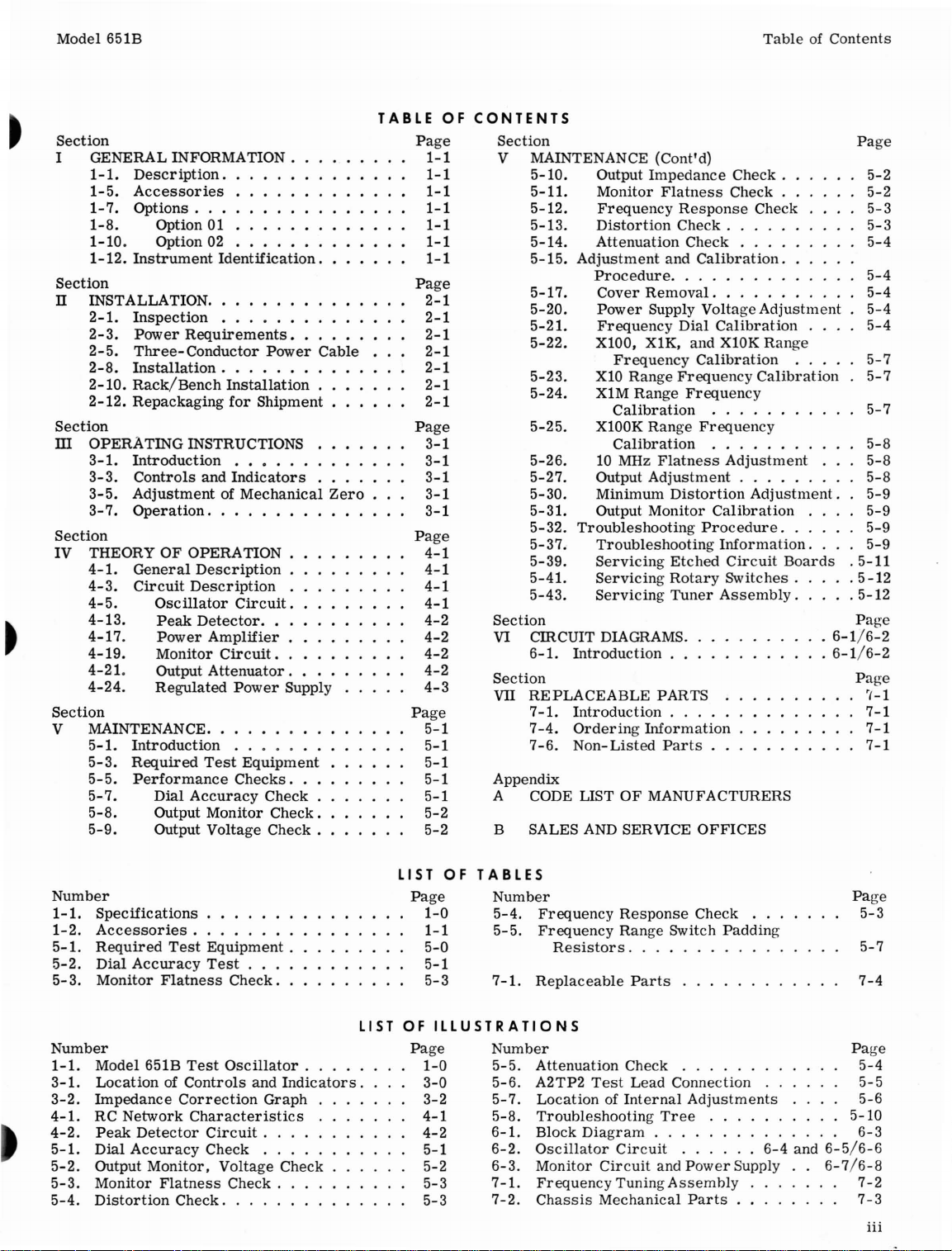
TableofContents
Section
I GENERAL INFORMATION .
1-1.
Description.
1-5.Accessories
1-7.
1-8.
1-10.
1-12.
Options
Instrument
...
Option 01
Option 02
Identification.
Section
n INSTALLATION .
2-1.
Inspection
2-3.
Power
2-5.
Three-Conductor
2-8.
Installation.
2-10.
Rack/Bench
2-12.
Repackaging
Section
ill
OPERATING
3-1.
Introduction
3-3.
Controls
3-5.
AdjustmentofMechanical
3-7.
Operation.
Section
IV
THEORYOFOPERATION
4-1.
General
4-3.
Circuit
4-5.
4-13.
4-17.
4-19.
4-21.
4-24.
Oscillator
Peak
Power
Monitor
Output
Regulated
Section
V MAINTENANCE .
5-1.
Introduction
5-3.
Required
5-5.
Performance
5-7.
5-8.
5-9.
Dial
Output
Output
. . . . . .
Requirements.
Power
. .
Installation.
for
Shipment
INSTRUCTIONS
.••...
and
Indicators
. . . . . . . . . . .
Description
Description
Circuit.
Detector
..
Amplifier
Circuit
..
Attenuator
Power
. . • . . . .
Test
Equipment
Checks
Accuracy
Monitor
Voltage
Check.
Check.
Check.
•
.
Supply
...
Cable
Zero
TABLE
Page
Page
Page
Page
Page
OF
1-1
1-1
1-1
1-1
1-1
1-1
1-1
2-1
2-1
2-1
2-1
2-1
2-1
2-1
3-1
3-1
3-1
3-1
3-1
4-1
4-1
4-1
4-1
4-2
4-2
4-2
4-2
4-3
5-1
5-1
5-1
5-1
5-1
5-2
5-2
CONTENTS
Section
V MAINTENANCE (Cont'd)
5-10.
5-11.
5-12.
5-13.
5-14.
5-15.
Output
Monitor
Frequency
Distortion
Attenuation
Adjustment
Impedance
Procedure
5-17.
5-20.
5-21.
5-22.
Cover
Removal.
Power
Supply Voltage
Frequency
X100, X1K, and XlOK
Frequency
5-23.
5-24.
X10
X1M
Range
Range
Calibration
5-25.
X100K
Range
Calibration
5-26.
5-27.
5-30.
5-31.
5-32.
5-37.
5-39.
5-41.
5-43.
10 MHz
Output
Adjustment
Minimum
Output
Monitor
Troubleshooting
Troubleshooting
Servicing
Servicing
Servicing
Section
VI
CmCUIT
6-1.
DIAGRAMS.
Introduction.
Section
VII
REPLACEABLE
-1.
Introduction.
7
7-4.
7-6.
Ordering
Non-Listed
Information
Appendix
OF
A CODE LIST
MANUFACTURERS
B SALES AND SERVICE
Flatness
Response
Check.
Check
and
Calibration.
.....
Dial
Calibration
Frequency
Frequency
Flatness
Distortion
Etched
Rotary
Tuner
.
PARTS
Parts.
OFFICES
Check.
Check.
Check
..
Calibration
Calibration
Frequency
Adjustment
Adjustment.
Calibration
Procedure.
Information.
Circuit
Switches.
Assembly.
Adjustment
Range
. .
.
. .
Boards
.
.
Page
5-2
5-2
5-3
5-3
5-4
5-4
5-4
5-4
5-4
5-7
5-7
5-7
5-8
5-8
5-8
5-9
5-9
5-9
5-9
.5-11
.5-12
.5-12
Page
6-1/6-2
6-1/6-2
Page
'1-1
7-1
7-1
7-1
Number
1-1.
Specifications.
1-2.
Accessories
5-1.
Required
5-2.
Dial
Accuracy
5-
3.
Monitor
Number
1-1.
Model 651B
3-1.
LocationofControls
3-2.
Impedance
4-1.
RC
4-2.
5-1.
5-2.
5-3.
5-4.
Network
Peak
Detector
Dial
Accuracy
Output
Monitor
Distortion
Test
Flatness
Test
Correction
Characteristics
Monitor,
Flatness
Check
. . . . . .
Equipment.
Test
. . .
Check.
Oscillator.
and
Graph
Circuit.
Check
. . . .
Voltage
Check.
.
.
Indicators.
. . .
Check
.
LIST
LIST
OF
Page
1-0
1-1
5-0
5-1
5-3
OF
ILLUSTRATIONS
Page
1-0
3-0
3-2
4-1
4-2
5-1
5-2
5-3
5-3
TABLES
Number
5-4.
5-5.
7
-1.
Number
5-5.
5-6.
5-7.
5-8.
6-1.
6-2.
6-3.
7-1.
7-2.
Frequency
Frequency
Resistors
Replaceable
Attenuation
A2TP2
LocationofInternal
Troubleshooting
Block
Oscillator
Monitor
Response
Range
....
Parts
Check
Test
Lead
Diagram.
Circuit
Circuit
Check
Switch
. . . . . . . .
Connection . .
Adjustments
Tree
. . . . . .
. . . . . . . . . . .
and
Power
FrequencyTuningAssembly
Chassis
Mechanical
Parts.
Padding
6-4
Supply
. . .
and
5-10
..
6-5/6-6
6-7/6-8
Page
5-3
5-7
7-4
Page
5-4
5-5
5-6
6-3
7-2
7-3
iii
Page 6

Section
I
Model 651B
Frequency
calibration:1to
Frequency
Flat
Range: 10 Hz to10MHz, 6
10.
Response:
within:
±2%
100 Hz to 1 MHz
±3%10Hzto100 Hz
±4%
1 MHz to10MHz*
Dial
Accuracy:
±10%
line
±2%,
(Including
voltage
variation).
100 Hz to 1 MHz
±3%,10Hzto100 Hz, 1 MHzto10
Output: 200
(3.16V)into 600
mW
(3.16V)
ohms;6.32
into50ohms;16mW
Attenuator:
Range:
Overall
range;
90
dBin10dBsteps
Accuracy:
±O.2dB
±D.
. 1 mV
1 dB.3mV
Figure
warm-up
Vintoopen
range
1-1.
bands.
drift
to 3V
Model 651B
Table
and
MHz
circuit.
1-1.
Specifications
dial
Test
Oscillator
Amplitude
Control:
Output Monitor:
put of
attenuatorinvoltsordB. Top
calibratedinvolts,
in dB.
Accuracy:
Flatness:
Distortion:
less
and
Hum
rated
Less
than2%at10MHz.
Noise:
output.
Temperature
20dBrange
Voltmeter
±2%atfull
±1%atfull
±2%atfull
4 MHz
than
Less
monitors
bottom
scale
scale
scale,
scale.
20Hzto
10Hzto20Hz,
to10MHz
1%,10Hzto5 MHz,
than
0.05% of
Range: 00to+500C.
(nominal).
levelatin-
scale
calibrated
4 MHz
maximum
1-0
*This
put. The
ohms
specification
applies
response
outputisaffected
above
onlyat50
1 MHzatthe
by
capacitive
ohm
out600
loads.
Power:
115V/230V
Dimensions:
deep
(132,6 x 425 x 336 mm).
5-7/32"
±10%,
high.
50
to 1000 Hz,
16-3/4"
wide.
30watts.
13-1/4"
01810-1
Page 7

Model 651B
Section I
1-1.
DESCRIPTION.
1-2.
The
torisa
eringafrequency
oscillator
adjustable
600
in
Figure
Table
Model 651B
for
differences
Options 01 and 02.
1-3.
panel
vides
with
The50ohm
source
1-4.
is
constantly
byaninternal
scales
erencedto1
ATTENUATOR,inconjunction
control,
when
Hewlett-Packard
wide
range
capacitance-tuned
range
hasastable
from10microvoltsto3.16
ohms.
transmission
The Model 651B
1-1
and
the
1-1.
This
manualiswritten
Test
Oscillator;
between
Two output
output
an output
impedanceisdesired.
The
Model 651B
for
RMS voltage
providesamonitored
matched
impedances
connectors.
withanimpedance
lines
connector
monitoredatthe
voltmeter.
milliwatt
into a50or
Model 651B
from10Hzto10
sine-wave
Test
specifications
the
standard
The
and
many
providesanoutput
Test
Oscillator
The
readings
into50ohms.
600 ohm load.
GENERAL
Test
oscillator
output
Oscillatorisshown
for
refertoparagraph
instrument
are
providedatfront
600 ohm
thatiscompatible
distribution
input of
voltmeter
and
adBm
with
the
output of
Oscilla-
MHz.
signal
volts
into50or
are
given
the
standard
connector
systems.
where
output voltage
the
attenuator
has
scale
The
OUTPUT
AMPLITUDE
desired
SECTION
INFORMATION
1-7.
cov-
The
that
1-7
and
pro-
a low-
two
ref-
level
is
in
1-8.
1-9.
Oscillator
tor
panel
been
the
1-10. OPTION 02.
1-11.
Oscillator
ohms.
referencedto1
1-12.
1-13.
serial
of
with
sheets
between
in
I
OPTIONS.
OPTION 01.
Option 01isa
that
referencedto1
OUTPUT ATTENUATOR dBm
changedtocorrespond
600n
output
Option 02isa
that
has
Also,
INSTRUMENT
Hewlett-Packard
number
the
serial
those
supplied
this
manual.
the
(000-00000).
numberonyour
on
the
your
instrument
standard
has
the
milliwatt
connector
standard
output
output
milliwatt
title
with
the
dBm
(-80to+10
impedancesof75
monitor
into 75
IDENTIFICATION.
usesatwo-section
pageofthis
manual
and
-hp-
Model 651B
scaleofthe
into 600
with
the
-hp-
Model 651B
has
ohms.
If
the
first
instrument
manual,
will
define
the
Model 651B
output
ohms.
markings
signal
DBM).
ohms
the
dBm
eight-digit
three
do not
differences
described
Test
moni-
Thefront
have
level
at
Test
and 600
scale
digits
agree
change
1-5.
ACCESSORIES.
1-6.
Table
which
will
-hp-
Model10110A,
Converts
connectors.
-hp-
Model 11004A
Provides
from
1-2
containsalist
increase
single-ended
the
a BNC
fully
of
the
accessories
usefulnessofthe
BNCtoBindingPostAdapter:
connectortobinding
Line-Matching
balanced
135nor600n
input.
Model 651B.
Transformer:
Table
post
output
1-2.
1-14.
instrument
States.
Accessories
-hp-
-hp-
If
Model 11005A
Provides
single-ended
Model 11048B
Precision
male
a
and
letter
was
fully
input.
50n
female
prefixes
manufactured
Line
balanced
Feed-Thru
feed-thru
BNC
the
Matching
600n
termination
connectors.
serial
Termination:
number,
outside
Transformer:
output
the
from
with
the
United
01810-1
1-1
Page 8
Model651B
Section
IT
2-1.
INSPECTION.
2-2.
This
instrument
mechanically
and
electrically
shouldbephysically
perfect
this,
damageintransit.
sories.
instrument
graph
warranty
2-3.
2-4.
230 Vac,
converted
the
so
the
ere,
electrical
the
instrument
order
Also,
and
test
the
using
the
5-5.Ifthereisdamageordeficiency,
on
the
inside
POWER
REQUIREMENT.S.
The Model 651B
50
- 1000 Hz.
from
115to230 volt
positionofthe
that
the
designation
nominal
slow-blow
slide
voltage of
fuseisused
operation.
2-5.
THREE-CONDUCTOR
2-6.
To
Electrical
mends
ed.
that
All
protect
Manufacturers'
the
Hewlett-Packard
operating
instrument
withathree-conductor
ged intoanappropriate
strument.
prong
2-7.
ing
the
three-prong
green
2-8.
2-9.
forenospecial
instrument
temperature
The
offset
connectoristhe
To
preserve
instrument
pigtailonthe
INSTALLATION.
the
fromatwo-contact
to
two-prong
adaptertoground.
The Model 651Bisfully
coolingisrequired.
should notbeoperated
exceeds
INSTALLATION
was
carefully
before
freeofmarsorscratches
upon
receipt.
shouldbeinspected
check
electrical
procedure
front
coverofthis
will
operate
The
instrument
operation
switch
locatedonthe
appearingonthe
the
power
for
POWER
personnel,
Association
panel
and
instruments
power
cable,
receptacle.
pinonthe
ground
wire.
protection
adapter
transistorized;
550C (131
o
inspected
shipment.
To
for
for
supplied
performance
outlined in
from
either
canbeeasily
by changing
rear
switch
source.
both
A
115 and 230 volt
CABLE.
the
(NEMA)
cabinetbeground-
are
equipped
which, whenplug-
grounds
power
cable
feature
when
outlet,
and
connect
However,
where
F).
the
SECTION
both
It
and
in
confirm
physical
acces-
of
the
Para-
see
the
manual.
115
or
panel,
matches
0.4
amp-
National
recom-
the
in-
three-
operat-
use
a
the
there-
the
ambient
II
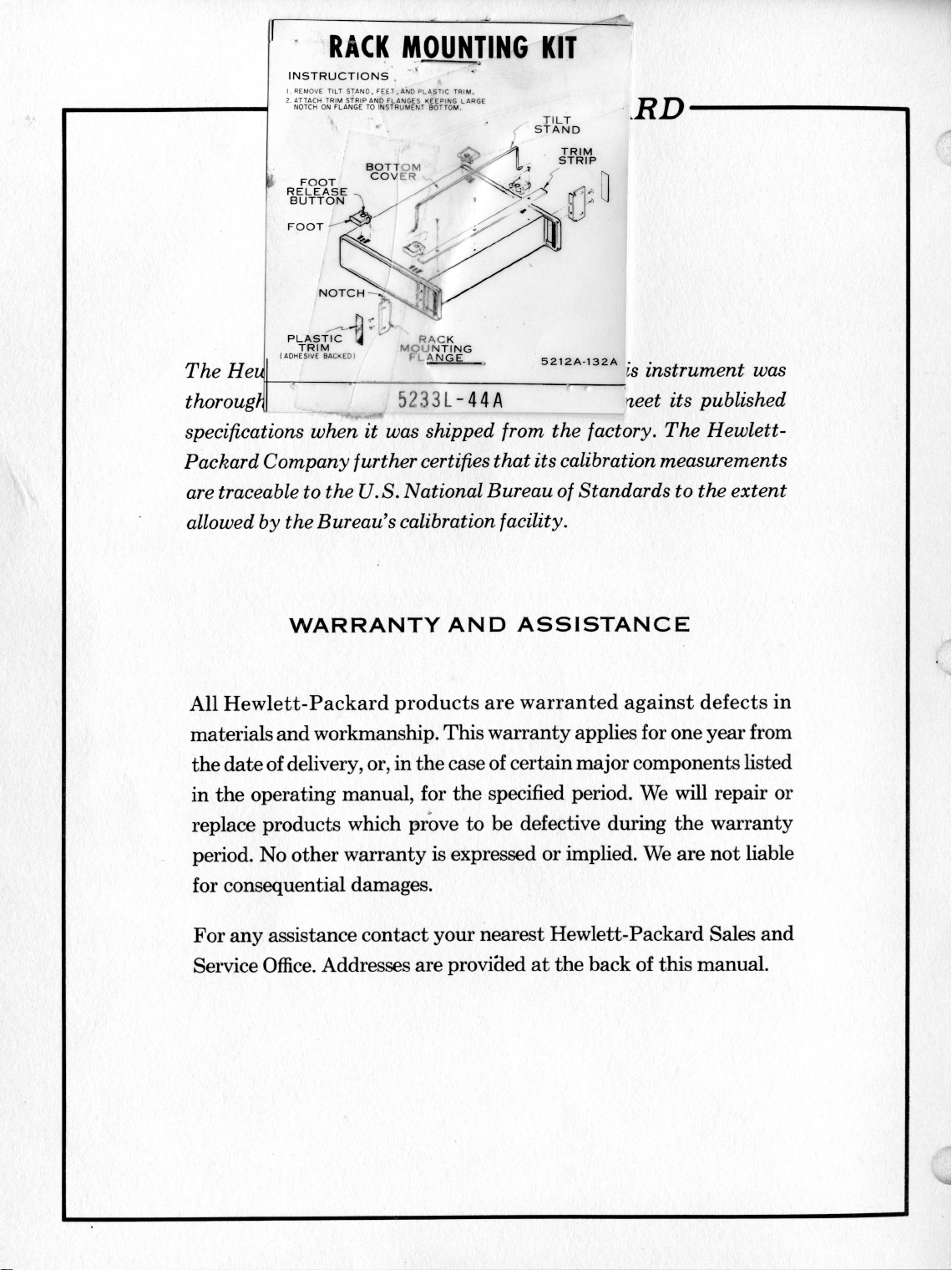
2-10.
2-11.
type
type)
version
accomplishedbyusing
instructions
2-12.
2-13.
for
local
B
If
RACK/BENCH
The
Model 651Bisinitially
instrument
with
plastic
(unless
feet
toarack-mounted
furnished
REPACKAGING
The
followingisa
shipment.Ifyou have any
-hp-
Sales
and
for
office
locations.
------NOTE-----
If
the
instrumentistobeshipped
to
Hewlett-Packard
or
repair,
strument,
and
indicating
repairtobe
the
model
number
numberofthe
correspondence,
strumentbymodel
a.
number
Place
and
instrument
available.
able,asuitable
your
nearest
original
containerisnot
b.
Wrap
before
c.
Use
instrument
placinginan
plenty of
sidesofinstrument
with
cardboard
d.
Place
instrument
heavy
carton
strong
e.
Mark
tapeormetal
shipping
strument,""Fragile"
INSTALLATION.
shippedasa
ordered
and a
specificallyasa
tilt
standinplace.
instrument
the
rack
mounting
with
your
instrument.
FOR
SHIPMENT.
general
guide
questions,
Service
Office. (See Appendix
)
for
service
attachatagtothe
identifying
the
the
service
accomplished;
and
full
serial
instrument.
identify
the
number,
serial
If
original
one
-hp-
Sales
number
in
prefix.
original
containerisnot
canbepurchased
and
used,
in
heavy
inner
container.
packing
and
material
protect
strips.
and
inner
or
wooden box and
bands.
container
with
etc.
bench-
rack
Con-
can
be
kit
and
for
repackaging
contact
your
in-
owner
or
include
In
any
in-
serial
container. if
avail-
from
Service
Office.
paperorplastic
around
panel
container
"Delicate
seal
all
faces
in a
with
In-
01810-1
2-1
Page 9

Section
ill
OUTPUT
ATTENUATOR
AMPLITUDE
VERNIER
Model65lB
®- 0
"''i
@D@
II
o I
~~--
-'@
~o
FREQUENCY Dial:
within
'multiplied by
quency of
CD
Output Monitor (M1):
CD
of
Mechanical
CD
tortobe
mentisoff,
each
frequency
range
the
instrument.
FREQUENCY RANGE Switch (S1):
one of
six
frequency
1 MHz.
the
test
oscillator
Zero
Adjust: Allows output
mechanically
Varies
settingisthe
ranges,
range.
Monitors
output.
zeroed,
output
Dial
from10Hz
when
0 0
frequency
reading
output
Selects
the
amplitude
instru-
fre-
•
to
moni-
0)
AMPLITUDE COARSE and FINE
Controls
PUT
eD
FREQUENCY VERNIER:
frequency
o LINE
applies
lamp
power.
amplitudeofsignal
ATTENUATOR.
adjustment
ON
Switch (S3) and
primary
glowstoindicate
powertoinstrument;
for
applicationofprimary
® 115/230 V Slide Switch (S4):
to
operate
either
fromaprimary
115 Vacor230 Vac.
Controls:
appliedtoOUT-
Providesafine
FREQUENCY
Pilot
Lamp:
Sets
power
Switch
instrument
source
dial.
pilot
of
3-0
OUTPUT ATTENUATOR:
cillator
Output
output
600(20
output in nine
Connectors
signal,atimpedance
(75n
and
stepsot10 dB
(J2
and
600n
on Opt. 02).
Attenuates
J3):
levelsof50n
Figure
test
os-
each.
Provides
3-1.
the
and
LocationofControls
@ FUSE
from
@
Primary
primary
and
(F1):.
0.4
overloads.
Power
powertotest
Indicators
amp
fuse
Connector
oscillator.
protects
(J1):
instrument
Connects
01810-1
Page 10

Model 651B Section m
3-1.
INTRODUCTION.
3-2.
The
Model 651B
stable
pedance
quency of
and
the
sine
levels
output
wave
of 600
the
outputisvariable
power
microvoltsto3.16
The
amplitudeofthe
output
3-4.
of
and
3-5.
3-6.
the
651Bisin
erating
the output
accuracy
monitor,
3-3.
CONTROLS
Figure
all
the
front
indicatorsonthe
ADJUSTMENT
The
output
meter
temperature,
monitorasfollows to obtain
and
a.
Turn
M1.
3-1
and
pointer
normal
mechanical
651B on and allowitto
output
identifies
Test
thatisavailableatoutput
ohms
level
volts
into 600
output
AND
INDICATORS.
rear
panel
Model 651B.
OF
monitorisproperly
rests
over
operating
andisturned
stability
least20minutes,tolet
reach
normal
b.
Turn
651B off, and allow30seconds
operating
capacitorstodischarge.
c.
3-7.
3-8.
as
follows:
a.
Insert
point
and
over
OPERATION.
To
Connect
pen) into
rotate
zero.
operate
pointed
wheel
the
primary
object
recess
until
651B
(115/230V,50to1000
switchS4to
b.
Turn
cator
of
LINE
lamp
primary
proper
ON
switchtoON
will
glow,
power.
c. Set FREQUENCY RANGE
QUENCY
Dialtodesired
d. Set OUTPUT ATTENUATOR
voltage
range.
OPERATING
Oscillator
and50ohms.
from10Hzto10
can
be
varied
or
50
willbeindicated
and
describes
controls,
MECHANICAL
zero-set
the
zero
mark,
positionatnormal
off.
operate
the
meter
temperature.
(suchastip
on
adjustment
meter
pointerisexactly
Test
Oscillator,
ac
power
position.
to
HZ),
and
position.
verifying
switch
output
switchtodesired
SECTION
generates
The
from
ohm
loads.
on
the
function
connectors,
ZERO.
when
and
Zero-set
maximum
for
movement
for
of
ball-
wheel,
proceed
651B
set
slide
Indi-
application
and
FRE-
frequency.
III
INSTRUCTIONS
e. Connect loadtooutput
a
imfreMHz,
10
the
the
op-
at
all
f.
g.
connector
impedance
Adjust
put
voltage,
The
valueofthe
level
The
output
plying
itor
which
AMPLITUDE
as
output
monitor,
in dBm
voltage
the
monitor
scale
multiplier
matches
indicated
impedance
controls
on output
Ml,
for
indicates
output voltage, and
for
resistive
loadsof50
levelisobtained by
scale
readingsbythe
which
appears
desired
OUTPUT ATTENUATOR switch.
following
tion
651B output
other
equation
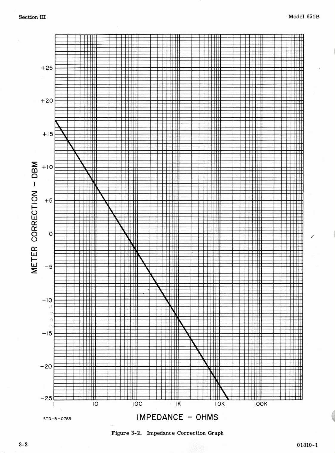
graphofFigure
power
than
those
markedonthe
and
3-2
level
the
impedance
to obtain
in dBm,
output
tors.
Output Voltage = RL+ R
X2V
S
Where,
R
= Load
L
R
=
S
V =Model 651B OutllutMonitorReading
m
Problem:
50
ohm output
output
volts,
on
actual
of
monitor
with
the
1. 0 volt
output
the
Model 651B.
Solution:
Resistance
(Terminating
sistance)
Source
Resistance
(Output
anceofOscillator
A 600 ohm loadisplaced
connector.
indicates
the
OUTPUT ATTENUATOR
(+10,
dBm)
voltage
The
actual
The Model 651B
an
output of
range.
and
power
level
output voltageiscalcu-
latedasfollows:
Output Voltage = 600 +
600
50
X 2 (0.
1.66volts
The
indicated
dBm
for
the
3.0
volt
power
levelisthe
indicated
factor
of
obtained
Figure
rectionof-10.8
ohm load.
dBm [17.3 dBm +
an
output
power
3-2.
The
power
level
voltage
(+20
dBm)
range.
algebraic
level
and
from
the
For
this
dBmisobtained
actual
power
(-10.8
would
of 1. 66
The
sum
the
correction
impedance
exampleacor-
levelis+6. 5
dBm)] .
having
of load.
monitor.
the
the
power
ohms.
multi-
mon-
on
Use
the
correc-
the
Model
for
loads
connec-
m
Imped-
on
0.9
Find
(indBm)
9)
=
be
17. 3
volts
actual
of
the
graph
for
a 600
an
out-
rms
the
Re-
the
set
the
on
01810-1
3-1
Page 11
Section
~
m
Cl
Z
o
~
u
w
c:::
c:::
o
u
c:::
w
~
w
~
ill
+25
+20
+15
"
"
Model 651B
"
+10
I
"
+5
"
"
"
-5
o
"
"
/
"
3-2
-10
-15
-20
-25
'lTD-B
I
)
"
"
-y
-y
1
-
0783
10
Figure
100
IMPEDANCE
3-2.
Impedance
IK
OHMS
Correction
10K
Graph
lOOK
01810-1
Page 12
Model 651B
Section
IV
4-1.
GENERAL
4-2.
The Model 651B
oscillator,
tor,
and
monitor
strumentisshown in
circuit
erateastable,
is
detector
voltagetothe
appliedtothe
circuitisusedtoincrease
at
improve
with
providesameansofattenuating
put
itor
the
provides
4-3.
4-4.
ing
4-5.
4-6.
signaiatthe
and FREQUENCY Dial
RC
consistingofan
a
in
conventional
resistive
the
ance
4-7.
possiblebythe
back.
quency
lifier
to
sitivetofrequency.
will
voltagetosustain
4-8.
of
SlC1
sitive
the
main
The RC
tionshipofthe
uses
appliedtothe
circuit
the50ohm
the
changing output
connectors
circuit
inputtothe
all
CIRCUIT
Refer
discussion.
OSCILLATOR CIRCUIT.
The
oscillator
bridge
resistive
the
Model 651B
voltage
conventional
Zl,
which
Oscillationatthe
Positive
sensitive
A2Q2 and A2Q3;
the
differential
the
positive
The RANGE switch,
resistors
through
RC
networks
instrument.
frequency
components
DESCRIPTION.
Test
power
amplifier,
circuit.
Figure
a modified
distortionless
power
providesadegenerative
oscillator
power
amplifier.
and
600 ohm output
frequency
loads.
in nine
continuously
attenuator.
voltages
to
frequency
networkisa modified
voltage
Wein
and
SlC13) to
positive
requiredbythe
DESCRIPTION.
Figures
circuit
RC
frequency
divider
Test
bridge
divider
Wein
bridgeisreplaced
consists
use
of both
feedbackisprovided
RC
networktothe
negative
amplifier
Onlyatthe
feedback
oscillation.
capacitors
for
The
FREQUENCY
tuning
elements
maintain
Oscillator
peak
A
block
6-1.
Wein
bridge
amplifier
circuittostabilize
the
stabilityofthe
The
stepsof10
monitors
The
6-2
thru
generatesasinusoidal
selectedbythe
locatedonthe
network. The W
Oscillator
circuitinthe
network. The
of A2CR6
selected
positive
throughanetwork
exceed
Sl,
(SlR1
establish
the
six
feedback
SECTION
THEORY
includes
detector,
diagramofthe
The
networktogen-
sine
wave
circuit.
The
power
output
selective
selects
the
power
connectors
output
the
signalatthe
dB each. The
the
regulated
651B
6-4
front
Wein
differs
and
frequencyismade
and
differential
feedbackisprovided
selected
the
negative
through
the
frequency
frequency
Dial
C1A, C1B, and C1C.
proper
voltage. At
attenua-
oscillator
signal
The
feedback
the
signal
amplifier
available
and
ou,tput
signal
for
bridge
combinations
signal
attenuator
level
power
circuits.
the
follow-
RANGE
panel. The
circuit,
network
ein
from
designofthe
resistor
with
imped-
A2CR7.
negative
throughafre-
insen-
frequency
feedback
SlR24,
ranges
varies
phase
frequen-
OF
an
in-
which
peak
to
out-
mon-
at
supply
switch
and
bridge
the
in
feed-
amp-
and
sen-
of
the
rela-
IV
OPERATION
cies
where
phase
Figure
At
frequencies
feedback
sufficient
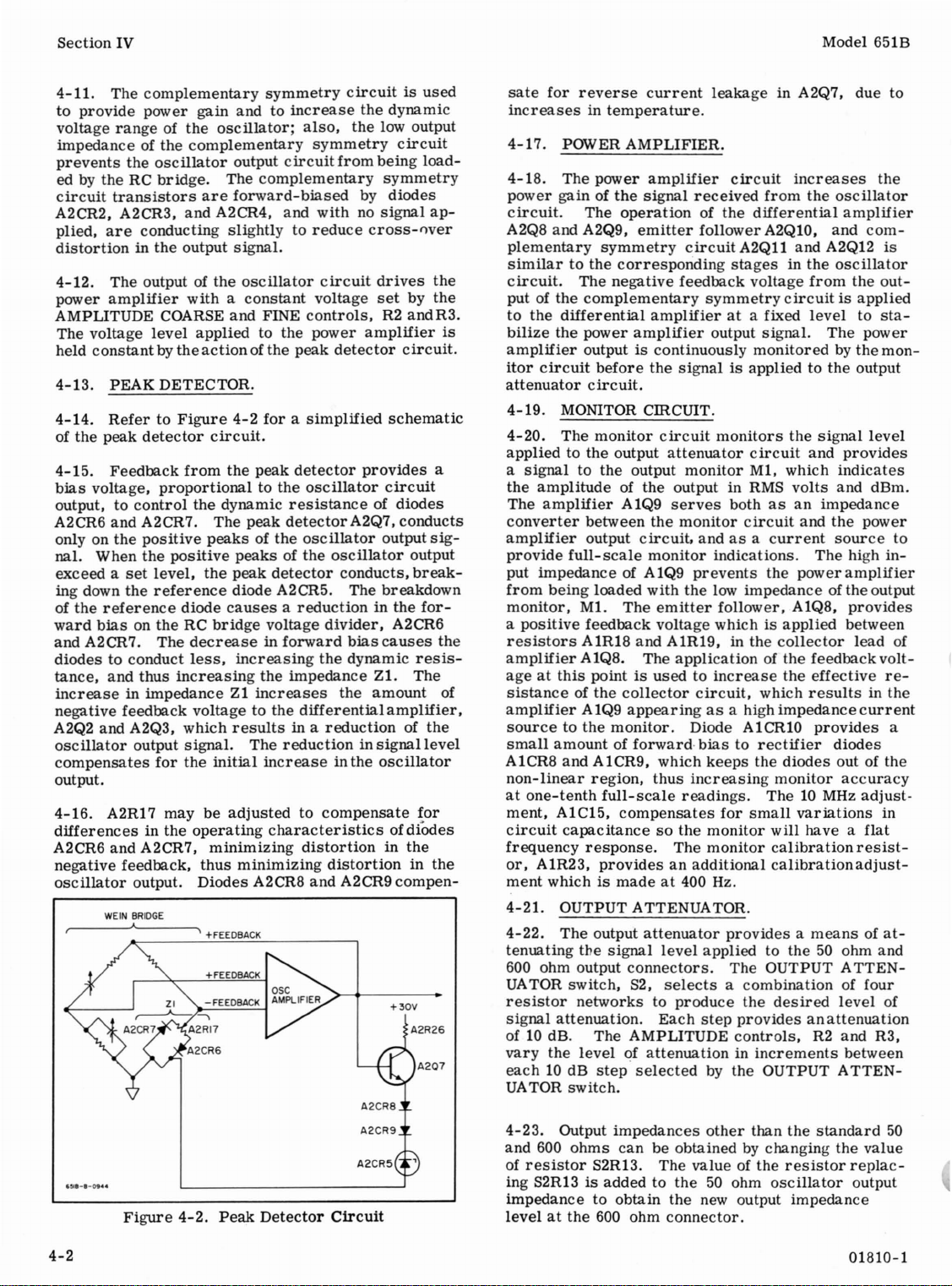
4-9.Afield
impedance
input
provides
impedanceofthe
four
frequency
pedance
being
ential
quency
on
the
valuesinthe
4-10.
from
amplifier
plementary
emitter
from
cuitisapplied
the
collector
quency
ageatthis
tanceofthe
impedanceofthe
collector
The
increaseinthe
in
the
back
quency
A2R9
followeratthe
Xc =R,
with
the
4-1)and
voltageisneitherofthe
amplitudetomaintain
effect
converter
impedance
a high
added
loadedbythe
amplifier.
ranges.
X100K
the
the
loop
voltageisremovedonthe
exceeding
F
p
F
and
RC
The
difference
bridge
A2Q2 and A2Q3, andisappliedtothe
symmetry
follower
output of
circuit
ranges.
pointisusedtomake
collector
current
gainofthe
ranges
0.5
0.4
0.3
0.2
~//
0.1
,./
Fp =
POSITIVE
TO
AMPLIFIER
F =
FEEDBACKTORC
Figure
4-1.
the
positive
oscillator
exceeds
other
and low
impedanceinseries
differential
ranges
prevents
A2Q2
The
X1M
bridge.
circuitisamplifiedbydifferential
A2Q4. A
between
The
emitter
duetothe
the
higher
the
than
transistor,
becauseofits
noise
(X10 - XlOK). The high
theRCbridge
low input
and
impedance
ranges
between
circuit
the
complementary
resistors
of A2Q2, on
applicationofthe
load
follower
into
the
base
current
oscillator
valueofresistors
input
frequencies.
FREQUENCY
f
/
/
/
--
--
FEEDBACK
NETWORK
RC Network
feedback
output
where
baseofthe
voltage
negative
amplifier
impedanceofthe
A2Q3, on
A2Q5
positive
higher
impedanceofthe
feedback
Xc=
R,
right
oscillations.
A2Q1,isusedasthe
extremely
characteristics.
with
on
circuit
the
converterisbypassed
duetolower
the
feedback
and
feedback
symmetry
A2R8 and A2R9. in
the
first
feedback
the
effective
than
A2Q4.
emitter
resultsinan
circuit.
X100K and X1M
\
\//////
////
\
--
"'-
~
RATIO--
PHASE
6ScIA-S-IOA
Characteristics
voltageisin
(refer
the
phase
the
the
lower
A2Q6,
the
forcing
The
A2R8
/
-----
voltage.
positive
nor
high
input
lower
from
differ-
resistor
voltages
com-
through
voltage
four
resis-
input
follower.
increase
feed-
fre-
emitter
LAG
PHASE
LEAD
'to
of
It
im-
fre-
cir-
fre-
volt-
the
and
01810-1
4-1
Page 13
Section
IV
Model 651B
4-11.
to
voltage
impedanceofthe
prevents
ed by the RC
circuit
A2CR2, A2CR3,
plied,
distortioninthe
4-12. The output of
power
AMPLITUDE COARSE
The voltage
held
4-13.
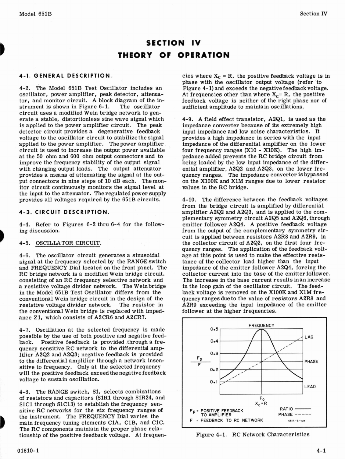
4-14.
of
4-15.
bias
output, to
A2CR6
only on
nal. When
exceed a
ing down
of
ward
and
diodes
tance,
The
complementary
provide
power
rangeofthe
the
oscillator
bridge.
transistors
are
conducting
amplifier
level
constantbythe
PEAK DETECTOR.
RefertoFigure
the
peak
detector
Feedback
voltage,
proportional
control
and
A2CR7. The
the
positive
the
positive
set
level,
the
reference
the
reference
biasonthe
A2CR7. The
to conduct
and
thus
symmetry
gain
andtoincrease
oscillator;
complementary
output
circuitfrom
The
complementary
are
forward-biased
and
A2CR4, and
slightlytoreduce
output
signal.
the
oscillator
withaconstant
and
FINE
applied
action
to the
ofthe
peak
4-2
forasimplified
circuit.
from
the
peak
detector
to the
the dynamic
resistance
peak
detectorA2Q7,
peaksofthe
peaksofthe
the
peak
detector
diode A2CR5. The
diode
causesareductioninthe
RC
bridge
voltage
decreaseinforward
less,
increasing
increasing
the
impedance
increaseinimpedanceZ1increases
negative
A2Q2 and A2Q3,
oscillator
compensates
feedback
output
for
voltagetothe
which
results
signal.
the
The
initial
differential
in a
reductioninsignal
increaseinthe
output.
4-16.
differencesinthe
A2CR6 and A2CR7,
negative feedback,
oscillator
A2R17
output.
WEIN BRIDGE
A
may
be
adjustedtocompensate
operating
characteristics
minimizing
thus
minimizing
Diodes
\
A2CR8
+FEEDBACK
circuitisused
the
also,
the
low output
symmetry
being
symmetry
by
withnosignal
cross-()ver
circuit
voltage
controls,
power
drives
set
R2
amplifier
detector
provides
oscillator
circuit
of
oscillator
output
oscillator
conducts,
breakdown
divider,
bias
causes
the
dynamic
Z1. The
the
amount
reductionofthe
oscillator
distortion
in
distortion
and
A2CR9
dynamic
circuit
load-
diodes
ap-
the
by
the
andR3.
is
circuit.
schematic
a
diodes
conducts
sig-
output
break-
for-
A2CR6
the
resis-
of
amplifier,
level
for
ofdiOdes
the
in
the
compen-
+30V
sate
for
reverse
current
increasesintemperature.
4-17.
4-18.
power
circuit.
A2Q8 and A2Q9,
plementary
similartothe
circuit.
put of the
to
bilize
amplifier
itor
attenuator
4-19.
4-20.
applied
a
the
The
converter
amplifier
provide
put
from
monitor,
a
resistors
amplifier
ageatthis
sistanceofthe
amplifierA1Q9
sourcetothe
small
A1CR8
non-linear
at
ment,
circuit
frequency
or,
ment
4-21.
4-22.
tenuating
600 ohm output
UA
resistor
signal
POWER
The
gainofthe
AMPLIFIER.
power
amplifier
signal
The
operationofthe
emitter
symmetry
corresponding
The
negative
complementary
the
differential
the
power
amplifierata fixed
amplifier
outputiscontinuously
circuit
before
the
circuit.
MONITOR
The
monitor
CmCUIT.
circuit
to the output
signaltothe
amplitude
amplifier
full-scale
impedance
being
positive
output
of the output in RMS
A1Q9
between
output
the
circuit,
monitor
of A1Q9
loaded
M1.
feedback
The
with
emitter
voltage
A1R18 and A1R19, in the
A1Q8. The
pointisusedtoincrease
collector
appearingasa high
monitor.
amountofforward·
and
one-tenth
A1C15,
A1CR9,
region,
full-scale
which
thus
compensates
capacitancesothe
response.
A1R23,
providesanadditional
whichismadeat400 Hz.
OUTPUT ATTENUATOR.
The
output
attenuator
the
signal
level
connectors.
TOR
switch,
S2,
selectsacombination
networkstoproduce
attenuation.
Each
received
follower
circuit
feedback
symmetry
output
signalisappliedtothe
attenuator
monitor
serves
monitor
andasa
prevents
the
applicationofthe
circuit,
Diode A1CRlO
biastorectifier
keeps
increasing
readings.
monitor
The
monitor
applied
step
of10dB. The AMPLITUDE
vary
the
levelofattenuationinincrements
each10dB
UA
TOR switch.
step
selected
by
leakage
in A2Q7, due to
circuit
from
increases
the
differential
A2Q10,
A2Qll
and A2Q12
stagesinthe
voltage
from
oscillator
amplifier
and
oscillator
the
circuitisapplied
level
to
signal.
The
monitoredbythe
output
monitors
bothasan
indications.
low
follower, A1Q8,
whichisapplied
the
circuit
M1, which
volts
circuit
and
current
the
power
impedance
collector
signal
and
provides
indicates
and dBm.
impedance
the
source
The
high
amplifier
of the output
provides
between
lead
feedback
the
effective
which
results
impedance
provides
diodes
the
diodes
monitor
out of the
accuracy
The10MHz
for
small
variations
will
have a
calibration
calibration
resist-
adjust-
providesameansofat-
to the50ohm and
The OUTPUT
ATTENof four
the
desired
level
providesanattenuation
controls,
R2 and R3,
between
the OUTPUT
ATTEN-
the
com-
is
outsta-
power
mon-
level
power
to
in-
of
volt-
re-
in the
current
a
adjust-
in
flat
of
4-2
Figure
4-2.
Peak
Detector
Circuit
4-23.
and 600
of
Output
resistor
impedances
ohms
can
S2R13. The
be obtained by changing
ing S2R13isaddedtothe
impedancetoobtain
levelatthe
600
ohm
the
connector.
other
value
of the
50
ohm
new output
than
resistor
oscillator
the
standard
the
impedance
50
value
replac-
output
01810-1
Page 14
Model 651B
Section IV
4-24.
4-25.
ages
power
supply and a
referenced
4-26.
tional
A1Q2isusedtoincrease
cuit,
volt
REGULATED POWER SUPPLY.
The
regulated
required
supply
-25
to the
The
+30
series
thus
adjustment,
regulator
improving
consists
by
volt
volt
power
the
test
series
+30
volt
regulated
voltage
A1R4,
of a
type.
supply
oscillator
+30
volt
regulated
circuit.
supplyisofthe
The
the
loop gain of
regulation.
sets
the
provides
circuits.
series
supply
emitter
+30
volt
all
volt-
The
regulated
which
conven-
follower
the
cir-
The
+30
and
-25
volt supply output
4-27.
tional
the
is
addedtolimit
the
limiter
to
inganexcessive
and A1CR7
against
or
The
series
+30
volt supply. A
load
current
conducts,
reduce
short
short
circuitsinthe
the
-25
level.
volt
regulated
regulator
the
output voltage
protect
circuits
type and
current
load
current
exceeds
causing
currentisremoved.
the
between
output of
supplyisoftheconven-
limiter,
the
set
the
series
level
control
the
operates
toaset
two voltage
the
the
A1Q7,
value. When
value, the
regulator
until
the load
Diodes A1CR6
transistor
-25
volt supply.
same
as
has
been
current
A1Q4
caus-
A1Q6,
supplies,
01810-1
4-3
Page 15

Section
V
Table
5-1.
REQUIRED
TEST
EQUIPMENT
Model 651B
Instrument
Oscilloscope
Electronic
RMS
Voltmeter
Distortion
DC Null
AC
Attenuator
Amplifier
Thermal
Voltmeter
Differential
Converter
Type
Counter
Analyzer
Voltmeter
Required
Passband:
Sensitivity:
Input
Range:
Accuracy:
Frequency
Voltage
Accuracy:±1%
Distortion
Range:
Accuracy:
Range: 3 V to 4 V
Accuracy:
Attenuation
Frequency
Gain: 40
Frequency
Input: 3
Output: 7 mV dc
Accuracy:
Frequency
10
Hz to10MHz
50
mV/cm
Impedance:1megohm
10
Hz to10MHz
± 5
counts
Range:
Range: 1 mVto6.32
Sensitivity:>42
10
J1.V
to30V
±2%offull
±0.1%
Range:90dB in10dB
Range:
dB
Range:
VRMS
±O.2%
Range:
Characteristics
10Hzto10MHz
dB
scale
10
Hz to10MHz
10
Hz to10MHz
10Hzto10MHz
V
steps
Recommended
-hp-
Model 175A
-hp-
Model 5244L
Electronic
-
hp-
Model 3400A RMS
Voltmeter
-hp-
Model 331A
-hp-
Model 419A
-hp-
Model 741A
Differential
Standard
-hp-
Model 355D VHF
Attenuator
-hp-
Model 461A
Amplifier
-hp-
Model 11049A
Thermal
Converter
Model
Oscilloscope
Counter
(withknown
AC-DC
Voltmeter/DC
(withknown
error)
error)
oto
10
mV
Terminating
Adapter
Reference
Resistance
Supply
See
Figure
a.
Resistor:
b.
Resistor:
c.
Resistor:
Battery:
d.
a.
Feedth.r6ugh,
Feedthrough,
b.
BNCtoBinding
5-3
for
fxd,
var,
var,
1.34V
500
6000
Post
schematic
65000±1%
5000
±5%
500
±5%
a.
-hp-
-hp-
b.
c.
-hp-
d.
Mallory
a.
-hp-
b.
-hp-
-hp-
Model 10111A
Part
No. 0811-0392
Part
No. 2100-0324
Part
No. 2100-1481
RM-42R
Model 11048B
Model 11047A
Adapter
5-0
01810-1
Page 16
Model 651B
SECTION V
MAINTENANCE
Section
V
5-1.
INTRODUCTION.
5-2.
This
section
information
Included
Calibration
cedures.
5-3.
5-4.
Model 651BislistedinTable
type of
quirements,
available
Table
fies
the
5-5.
5-6.
that
insure
operating
used
for
and
for
performance
ance
before
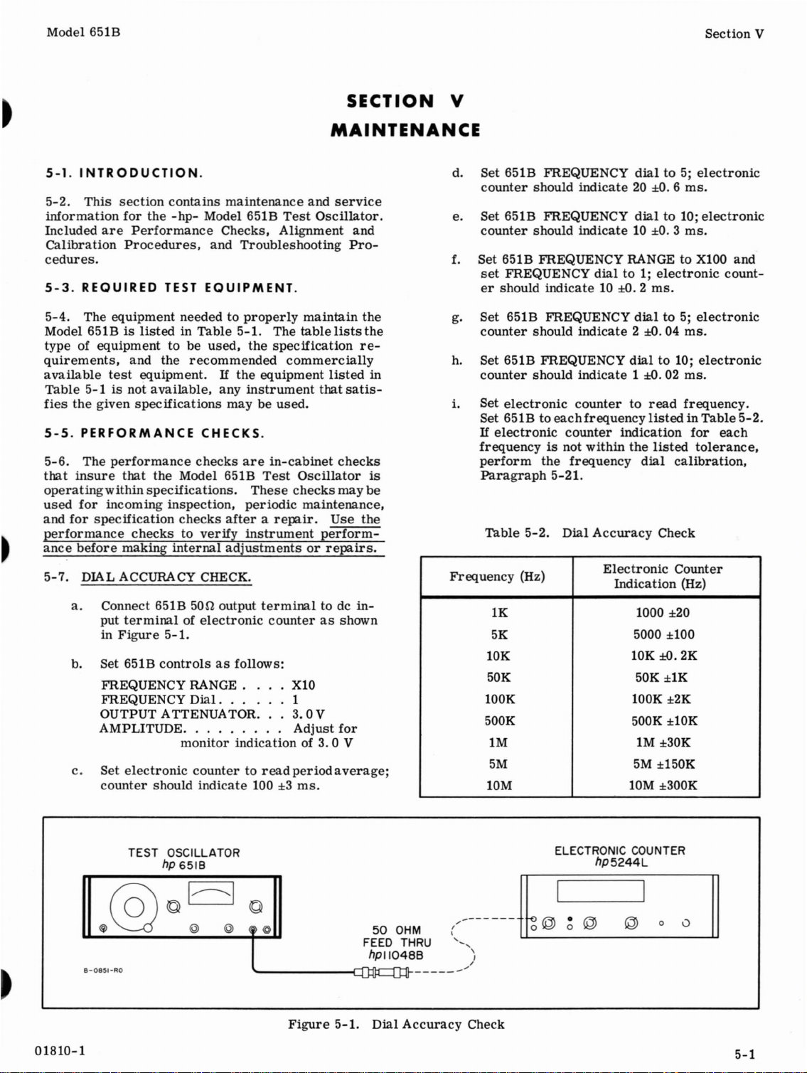
5-7.
a.
b. Set 651B
c.
for
are
Procedures,
REQUIRED
The
equipment
equipmenttobe
test
5-1isnot
given
PERFORMANCE
The
performance
that
within
incoming
specification
making
DIAL ACCURACY CHECK.
Connect 651B
put
terminalofelectronic
in
Figure
FREQUENCY
FREQUENCY
OUTPUT ATTENUATOR. . .3.0 V
AMPLITUDE. . . . . . . . .
Set
electronic
counter
contains
the
-hp-
Model 651B
Performance
and
TEST
EQUIPMENT.
needed to
used,
and the
equipment. If
specifications
specifications.
checks
recommended
available,
CHECKS.
checks
the
Model 651B
inspection,
checks
to
verify
internal
50n
5-1.
controlsasfollows:
RANGE..
Dial.
monitor
countertoread
should
indicate
maintenance
Checks,
Troubleshooting
properly
5-1.
the
the
equipment
any
instrument
maybeused.
are
Test
These
periodic
afterarepair.
instrument
adjustmentsorrepairs.
output
terminal
. . . . . 1
indicationof3.0
100±3ms.
and
service
Test
Oscillator.
Alignment
maintain
The
table
lists
specification
commercially
listed
that
in-cabinet
checks
counterasshown
X10
Adjust
period
checks
Oscillator
may
maintenance,
Use
perform-
to de
for
V
average;
and
Pro-
the
the
re-
satis-
be
the
in-
in
is
d. Set 651B FREQUENCY
counter
e. Set 651B FREQUENCY
counter
f. Set 651B FREQUENCY RANGEtoX100 and
set
er
g.
Set
counter
h.
Set 651B FREQUENCY
counter
i.
Set
Set 651Btoeach
If
frequencyisnot
perform
Paragraph
Table
Frequency
10K
50K 50K
lOOK lOOK
500K 500K ±10K
1M
5M
10M
should
should
FREQUENCY
should
651B FREQUENCY
should
should
electronic
electronic
5-2.
(Hz)
1K 1000 ±20
5K
indicate20±O.6ms.
indicate10±O.3ms.
indicate
indicate
indicate1±O.02ms.
countertoread
frequency
counter
within
the
frequency
5-21.
Dial
Accuracy
dialto5;
dialto10;
dialto1;
10
±D.
dialto5;
2
dialto10;
indication
the
Electronic
Indication
5000 ±100
10K
1M
5M
10M ±300K
electronic
electronic
electronic
2
ms.
electronic
±D.
04
ms.
electronic
frequency.
listedinTable
dial
for
listed
calibration,
Check
Counter
(Hz)
±D.
2K
±lK
±2K
±30K
±150K
tolerance,
count-
5-2.
each
01810-1
8-0851-RO
TEST OSCILLATOR
hp
6518
Figure
FEED THRU
5-1.
50
OHM
hPII048B
:::J~------""
01:[
Dial
Accuracy
ELECTRONIC COUNTER
hP5244L
(-----ntl@1
'-
\
"
I
/
Check
•
0
©
@
0
0
~
5-1
Page 17

Section
V
RMS
TEST
OSCILLATOR
hp 6518
Model 651B
VOLTMETER
hp
3400A
5-8.
5-9.
5-2
e-0852-RO
OUTPUT
a.
ConnectanRMS
terminal
UseanRMS
b.
Set
FREQUENCY RANGE . .
FREQUENCY
OUTPUTATTENUATOR
c.
Adjust
indication
should
indicationisnot
form
If
651B
(effectively
RMS
OUTPUT
Connect RMS
a.
inal
Set
b.
FREQUENCY RANGE . .
FREQUENCY
OUTPUTATTENUATOR
Adjust
c.
3.0Vindication
d.
Turn
voltmeter
0.3Vor
Turn
e.
CW; RMS
or
MONITOR CHECK.
of 651B
voltmeter
651B
controlsasfollows:
651B
amplitude
on output
indicate
the
monitor
desired,
----NOTE
When
turned
monitor
set
Thisisa
and
calibration.
of 651BasshowninFigure
651B
AMPLITUDE
greater.
the
connected
on open
voltmeter
amplitude
fully
will
one
division
normal
does
not
VOLTAGE CHECK.
voltmeterto500
controlsasfollows:
Dial.
651B AMPLITUDE
indication
less
(20 dB down).
AMPLITUDE
voltmeter
'---------------{~JO~Q:1)J~-
Figure
voltmeter
as
showninFigure
with
Dial.
. . .
controls
monitor.
3.0V±2%.
within
monitor
indication
CCW,
typicallybeoff-
requireamonitor
on RMS
this
calibration,
maybechecked
directly
circuit).
----
controls
the
up-scale.
indication,
. . . .
voltmeter.
controls
should
controls
should
to
shouldbe6 V
651B
.
controls
fully CCW; RMS
5-2.
Output
to
500
output
known
X100
4
3.0
RMS
IfRMS
tolerance,
Paragraph
RMS
are
X1K
10
3.0
be
on 651B fully
indicate
error.
V
fora3.0
voltmeter
voltmeter
voltmeter
In
this
output
5-2.
V
for
reduced
3.16
case,
term-
5-2.
per-
5-31.
with
±2%.
a
to
V
Monitor,
V
5-10.
5-11.
50
OHM
FEED THRU
hpll0488
Voltage
f.
g.
a.
b.
c.
d.
e.
f.
g.
h.
a.
Check
Disconnect
terminal
put
terminal.
load
(-hp-
Repeat
OUTPUT
Connect
voltmeter.
Set
FREQUENCY RANGE . .
FREQUENCY
OUTPUT
Adjust
indication
Inserta500feedthrough
and
cation
ing a
Remove
connect
651B.
Connect
voltmeter.
Adjust
indication
Inserta6000
voltmeter.
dropto3.0V±O.15V.
MONITOR FLATNESS CHECK.
Connect
reference
5-3,
putstominimum
DO NOT EXCEED RATED INPUT
THERMAL CONVERTER. ANY
LOAD OR HIGH VOLTAGE TRANSIENT
MA
stepscthrough
651B
651B
RMS
should
500
651B AMPLITUDE
setting
YDESTROY THERMOELEMENT.
(---------~~
'"
\
,
-
of 651B and
Model 1l047A).
IMPEDANCE CHECK.
500
controlsasfollows:
ATTENUATOR
on RMS
voltmeter.
output
the
the
6000
on RMS
nullmeter,
supplyto651Bas
/
----/
RMS
voltmeter
Replace
output of 651B
Dial.
. . .
amplitude
voltmeter.
dropto3.0
impedance.
500
feedthrough
cable
to
output of 651B
voltmeter.
load
between
RMS
voltmeter
thermal
651B
and
before
connectto6000
500
e of
controls
load
RMS
V
the
500
controls
reference
connecting.
from
500
output
out-
load
with
6000
this
paragraph.
directly
X1K
1
3.0V
between
voltmeter
±D.
directly
651B and RMS
indication
converter,
shown in Fibrure
OVER-
to RMS
fora6.0
651B
indi-
15V,verify-
load,
and
output of the
toRMS
fora6.
should
and
supply
OF
out-
01A10-1
V
dis-
OV
Page 18

Model
651B
TEST
OSCILLATOR
hp 6518
@6
$ © @ @
8-0853-
RO
©
90
Section
DC
NULL
VOLTMETER
hp
419A
~II@I
+ - 0 0
~lllllill
THERMAL CONVERTER
hp
1I049A
I
-
I
='
J
REFERENCE SUPPLY
r---------------
I
I
I
I
I
I
I
C
I
!
I
I I
L J
R2
500fi
R3
50n
RI
6500fi
---,
BTl
1.34V:
V
I
I
I
I
I
I
I
I
I
I
b.
Set 651B
controlsasfollows:
FREQUENCY
FREQUENCY
OUTPUTATTENUATOR
c.
d.
e.
Adjust
monitor
Adjust
Do not
is
Set
5-3,
a
settmg.
not
perform
graph
Table
651B AMPLITUDE
indicationof3.0
reference
readjust
obtained.
651Btoeach
and
adjust
nU.ll
indicationisobtained
If
the
within
the
the
5-31. '
5-3.
Monitor
Frequency
(Hz)
10
20
100
400
5K
50K
500K
1M
4M
10M
Figure
RANGE.
Dial.
.
. . .
controls
V.
supply
foranull
reference
frequency
supply
settinginTable
AMPLITUDE
for
651B
monitor
tolerances
monitor
listedinthe
calibration'
Flatness
Monitor
Indication
Min. Max.
2.94
2.94
2.97
2.97
2.97
2.97
2.97
2.97
2.97
2.94
5-3.
X1K
10
3.0V
for
a
indication.
once
null
controlssothat
each
frequency
indication
is
table,
Para-
Check
3.06
3.06
3.03
3.03
3.03
3.03
3.03
3.03
3.03
3.06
Monitor
Flatness
Check
5-12. FREQUENCY RESPONSE CHECK.
a.
b.
c.
Perform
setting
Adjust
meter
Adjust
Do not
stepsaand
FREQUENCY
651B
AMPLITUDE
indicationof7.0
reference
readjust
supply
reference
b of
dial
to 1.
controlsfora
mV.
for
supply
Paragraph
a null
obtained.
dial
d. Sweep FREQUENCY
If
the
null
ances
listedinTable
tions
and
e.
through
Repeat
range
Table
5-25.
stepsbthroughdfor
listedinTable
5-4
Frequency
Range
X10
XlOO
X1K
X10K
X100K
X1M
5-13.
DISTORTION CHECK.
a.
Connectadistortion
showninFigure
meter
indication
adjustments
Frequency
Null
Min. Max.
-420
IlV
-280
Il
-280
IlV
-280
IlV
-280
IlV
-560
IlV
5-4
slowly
exceeds
5-4,
perform
in
Paragraphs
each
5-4.
Response
Meter
Indication
V +280IlV
analyzertothe
indication.
once
from
the
the
frequency
Check
+420
IlV
+280
IlV
+280
IlV
+280
IlV
+560
IlV
651B
5-11,
null
null
1 to 10.
toler-
calibra-
5-22
as
is
8-0854
01810-1
-RO
TEST
OSCILLATOR
hp 6518
50
FEED THRU
hpll048B
,.....{'-l.J"tr]tr'------lj-"JiK...-
FIgure
5-4.
OHM
t
--!
- - - - - - - - - - - - -
Distortion
Check
DISTORTION
hp
ANALYZER
331A
5-3
Page 19

Section
V
TEST
OSCILLATOR
hp
6518
Model 651B
RMS
VOLTMETER
hP3400A
B-08:5,-RO
b. Set 651B
FREQUENCY RANGE
FREQUENCY
OUTPUT ATTENUATOR
AMPLITUDE. . . . . . .
c.
Distortion
analyzer,
d. Set 651Btoeach
(except
cause
analyzeris600 kHz) and
analyzer
be
tortion
minimum
graph
5-14. ATTENUATION CHECK.
a. Connect
RMS
Useanattenuator
----NOTE----
voltmeter
prongtotwo
theacpower
struments.
Set 651B
b.
FREQUENCY RANGE . •
. FREQUENCY
OUTPUT ATTENUATOR
Set
c.
Set
d.
e.
Adjust
indication
£.
Check
ing
attenuation
voltmeter
controlsasfollows:
Dial.
. . . 1
monitor
level
as
indicatedondistortion
should be
the
top
the
frequency
indication;
less
than1%for
levelisnot
distortion
5-30.
external
voltmeterto651B,asshowninFigure5-5.
Float
the
amplifier
by
controlsasfollows:
attenuator
amplifier
651B AMPLITUDE
attenuatoroneach
attenuation
gain
of 9 mV on RMS
is
indication
less
frequency
three
distortion
each
less
attenuator,
with
usingathree-
prong
cord
Dial.
. • .
switchto90dBposition.
switch
on
external
increased
should be 9mV±1%
..
frequency
limitofthe
adjustment,
known
and RMS
adapter
of both
X1K
3.0
Adjust
indicationof3.0
than
1%.
listedinTable
settings,
observe
level
frequency.
than
1%,
amplifier,
error.
on
in-
X1K
1
3.0V(+20
to 40 dB
controls
voltmeter.
rangebydecreas-
attenuator
on 651B. RMS
Figure
V
for
distortion
distortion
should
If
dis-
perform
Para-
and
dB)
position.
for
an
as
for
5-5.
V
5-3
be-
the
50
OHM
FEED THRU
hpll048B
Attenuation
5-15.
5-16.
calibration
adjustments
determinedbythe
is
locationofall
5-17.
5-18.
two
slide
off.
cedure.
5-19. To
taining
5-20.
5-21. FREQUENCY DIAL CALIBRATION.
Check
.3
mV
through
dB);
for.1mV
meter
g.
Repeat
with
and10MHz.
ADJUSTMENT
PROCEDURE.
The
not
within
COVER REMOVAL.
To
retaining
the
To
replace
screwsinthe
POWER
a. Connect a dc
positive
to
b.
Adjust
dc
c.
Connectdc
output,
indicate
outputisnot
of
put.
negative supply voltage;
A1R13*todecrease
a.
Remove
six
indication
stepscthrough
the
651B
followingisa
procedure
shouldbeperformed
Performance
specifications.
the
internal
remove
cover
removeaside
Figure
voltmeter
resistor
the
screws
about
the
SUPPLY
output,
6-3).
A1R4
voltmetertopower
connector
-25V±O.75V.Ifthe
Decrease
oscillator
retaining
3.0Vranges
range
setto100 kHz, 1 MHz, 5 MHz,
AND
for
toporbottom
from
1/2
cover,
cover,
VOLTAGE ADJUSTMENT.
voltmeter
foranindication of
.
within
A1R13* to obtain
value of A1R13*
screws.
(-70 dB), RMS
should be 9 mV
CALIBRATION
complete
the
Model 651B. The
Checks
Figure
adjustments.
the
sidesofthe
inchtothe
reverse
cover,
and
connector
point 2; de
tolerance,
negative supply voltage.
circuit
,--
~
(,
-',
"
/'
(-60 dB to
f of
this
adjustment
only ifithas
5-7
cover
rear,
the
remove
liftitoff.
to
power
point 1.
supply negative
voltmeter
negative
specified
increase
shieldbyremoving
©
@ @
±2%.
paragraph
that
the
shows
remove
cover,
and
removal
the
two
supply
+30
V onthe
change value
to
increase
value of
+20
volt-
and
been
651B
the
the
lift
pro-
re-
(Refer
should
supply
out-
it
5-4
01810-1
Page 20

Model 651B
Section V
,.....-----EE3
THE 651B CONTAINS VERY HIGH IMPEDANCE, HIGH FREQUENCY
CUlTS. CONTAMINATION
TUNING CAPACITOR
AND SUBSEQUENT DETERIORATION
INSTRUMENT. A
BARE FINGERS, AS SKIN OILS ARE
HANDLINGISNECESSARY, WEAR CLEAN COTTON OR RUBBER GLOVES.
DO
NOT USE A
GRAPHITE
AN ACCIDENTLY INTRODUCED PATH
DIFFICULT
A PRINTED CffiCUlT OR SWITCH, CLEANWITH A WEAK SOLUTION
WARM WATER AND MILD DETERGENT
OUGHLYWITH CLEAN WATER AND
BEFORE
ING SOLUTION
COMMERCIALMOISTURE SEALINGSPRA
OF
b. Set 651B
FREQUENCY RANGE . .
FREQUENCY
OUTPUT ATTENUATOR
AMPLITUDE
c. Connect 651Btodistortion
in
d.
Adjust
tortion
e. Connect RMS
meter
(gain
is
not
to
obtain
A2R16*
decrease
control
f.
AttachatesttoA2TP2,
lead
5-6.
voltage
shield
place
this
TEST
LEAD
Figure
controlsasfollows:
Figure
----NOTE-----This
adjustment
Dial
6518-RO
5-4.
A2R17
shouldbeless
adjustmentisa
calibration.
indication
control
within
specified
to
decrease
value
voltage.
withalK
Connect
maybemonitored
and
bottom
oscillator
time.
5-6.
A2TP2
OPERATING.
THESE AGENTS MAY CAUSE LEAKAGE PATHS.
Dial.
Controls
for
minimum
for
the
voltmetertoA2TP1;RMS
shouldbe110 mV ±10 mV
voltage).Ifgain
this
limit,
voltage.
of A2R16*toincrease
resistor.
test
leadsothat
coverinplace.
shield
Test
-------,
OF
THE SWITCHES. CffiCUlT BOARDS OR
WILL
CAUSE ffiGH IMPEDANCE LEAKAGE PATHS
OF
THE PERFORMANCE
VOID
TOUCHING ANY
PENCIL
PENCIL
TO
LOCATE. TO AVOID SURFACE CONTAMINATION
EXCEPT
. . .
.
analyzerasshown
distortion.
than1%(42dBdown).
preliminary
FREQUENCY
change
Increase
the
gain
control
and
isolate
as
showninFigure
with
and
bottom
Lead
Connection
TO
TRACE CffiCUlTS IN THE INSTRUMENT.
LEAD IS AN EXTREMELY
DO
NOT USE ALCOHOL OR ANY OTHER CLEAN-
DETERGENT AND WATER.
XIK
Fully
CW
3.0
V
Fully
CW
Dis-
volt-
control
value
voltage
ofA2R16*
value
voltage;
the
the
test
point
oscillator
Do not
cover
of
gain
test
re-
at
OF
THESE
EXTREMELY
OF
THIS
AFTER
ALLCNIITTO DRY
YTO
g. Connect
h.
i. Connect 651B to
j.
k.
1.
m.
cmCUlTS
CONTAMINATING.
GOOD
THE BOARDS;
CONDUCTOR AND
TYPEISSOMETIMES
REPAffi.
DO
Replace
coverofinstrument,
nectedtodc
age.
----NOTE
This
to
A2TP1,
enceinthe
procedures.
in
Figure
Turn
position.
Adjust
output
on
electronic
is
sameasrecordedinstep
Turn
651B output
indicated
is
not
coupler
until
Set
651B output
catedonelectronic
----NOTE
If
is
indicator,
Dial
taining
Dial
markondial
retaining
the
651B FREQUENCY
frequencyis10.2
FREQUENCY
specified
number1on
not
Cffi-
OF
THE
WITH THE
OF
OF
RINSE THOR-
COMPLETELY
NOT
APPLY
APPLICA
test
leadtoadcvoltmeter.
oscillator
voltmeter.
voltageisdirectly
gain
andisusedasa
5-1.
SlC2
and
counter)
frequency
on
electronic
within
(MP2,
linedupwith
remove
knob
and
screws.
until
number1linesupwith
screws
ANY
TION
circuit
control
following
electronic
SlC7
Dialtofully
965to970 Hz,
Figure
frequencyisobtained.
frequencyto1 kHz
counter).
-----
FREQUENCY
loosen
Slip FREQUENCY
indicator.
and
IF
shield
and
leaving
-----
voltage
alternately
and
shouldbe970 Hz
7-1),
markondial
FREQUENCY
four
test
Record
calibration
kHz
counter).
replace
A2TP2volt-
related
at
refer-
counterasshown
Dial
to fully
until
(as
indicated
voltageatA2TP2
h.
CW
loosen
and
slip
Dial
dial
re-
Tighten
knob.
bottom
lead
con-
CCW
651B
position.
If
651B
tuner
tuner
(as
indi-
(as
01810-1
5-5
Page 21

Section
V
f;:::::=========TOP=========~,
FI
o
Model 651B
S4
~
88~
rf
==========
1I
C7
C2
C4
C3
Rf=@@
AI
L3
@AIR4
AICI5@
L4
AIR23
@ 0
o A2
0
BOTTOM
I!IA2CI4
@A2R17
~A2C5
=========~,
0
0
S3
5-6
652A-C
-0818
Figure
5-7.
LocationofInternal
Adjustments
01810-1
Page 22

Model
5-22. X100, X1K,
6518
THE ADJUSTMENTS IN PARAGRAPHS 5-22 THROUGH 5-25
ARE HIGHLY CRITICAL
WILLHAVETOBE PERFORMED
ONLY IN RARE CASES. THE
VALUES OF THE RANGE SWITCH
RESISTORS WERE BRIDGED AT
THE FACTORY FOR OPTIMUM
PERFORMANCE,
RETICALLY SHOULD NEVER
HAVE
CHECK THE INSTRUMENT
FORMANCE BEFORE CHANGING
THE VALUES
RANGE SWITCH RESISTORS.
CAIJBRATION.
~3
AND
AND
THEO-
TOBE
CHANGED. DOUBLE-
OF
ANY
OF
AND
XlOK RANGE FREQUENCY
PER-
THE
Section
c.
If
either
of above
tolerance,
and
SlR14*
within
main
step
----NOTE
It
differenceinfrequency
endsofdial.
d. Set FREQUENCY
monitoring
accurate
and c
within
5-24. X1M RANGE FREQUENCY CALIBRATION.
----NOTE----
change
simultaneouslytobring
tolerance.
sameasthat
h{within
maybenecessarytosplit
electronic
within
until
±3%
over
frequenciesisnot
valueofresistors
A2TP2 voltage
recordedinParagraph
±D.
02 V).
----
between
Dialto2, 5, and 8,
counter.
±3%,ifnot,
FREQUENCY Dialisaccurate
its
entire
repeat
range.
frequency
must
Dial
within
SlR1
while
must
steps
V
*
re-
5-21,
be
b
"
a. Connect 651Btoelectronic
in
Figure
voltageatA2TP2.
b. Check
Dialat1, 5, 8, and10on X100, X1K, and
X10K
A2TP2. VoltageatA2TP2 should
relatively
of
the
c.
If
frequency
of
the
RANGE
respective
Change
at
same
on
all
recordedinParagraph
Frequency
Frequency
X10
X100
X1K
X10K
X100K
X1M
5-23. X10 RANGE FREQUENCY CALIBRATION.
a. Connect 651Btoelectronic
in
Figure
voltageatA2TP2.
5-1,
withdcvoltmeter
frequency
ranges
constant
FREQUENCY Dial.
FREQUENCY Dial, change
switch
value
timetokeep
ranges
Range
Range
5-1,
tracking
while
monitoring
from
ranges
range
Table
are
resistors
(refer
of both
(within
5-5
Switch
Padding
withdcvoltmeter
counterasshown
monitoring
of FREQUENCY
voltage
the1to10position
off on
the1position
associated
to
Table
resistors
voltageatA2TP2
±D.
5-21,
Padding
SlRl
SlR3*
SlR5*
SlR7*
SlR9*
SlRll
on
each
02Vfrom
step
h).
Resistors
Resistors
* and SlR14*
and SlR16*
and
SlR18*
and
SlR20*
and
SlR22*
* and SlR24*
counterasshown
monitoring
remain
value
with
5-5).
voltage
at
of
range
same
The
following
critical.
quency
with
all
place.
a. Connect 651Btoelectronic
in
Figure
voltageatA2TP2.
b. Set 651B FREQUENCY RANGEtoX1M, and
set
and
counter
and
graph
----NOTE
To
top
adjustments
Check FREQUENCY
acy
c.,
If
651B
put
enough
FREQUENCY
cover,
until
indicates
----NOTE---Replace
651B
A2C5.
5-1,
FREQUENCY
SlC10
indicates
voltageatA2TP2issame
5-21
accomplish
cover
and
will
monitor)orSlC5
range
and
651B
5 MHz.
frequency,
adjustments
Final
voltage
readings
instrument
with
step
voltageatA2TP2.
not
adjust
oscillates
bottom
mustbemade
covers
withdcvoltmeter
Dialto10.
tuning wand
10. 15 MHz (1.
h
(±D.
02 V).
----
stepb,remove
from
651B,
and
replace
Dial
oscillate
to
Dialto5,
(no
and SlC10 do not have
complete
A2C5
with
and
Then
repeat
covertocheck
after
adjusting
are
and
fre-
in
counterasshown
monitoring
Adjust
until
as
make
cover.
accur-
readingonoutstep
remove
tuning
electronic
step
SlC5
electronic
5%
high),-
in
Para-
b,
set
bottom
wand
counter
b.
b. Set 651B FREQUENCY RANGEtoX10 and
set
01810-1
FREQUENCY Dial
counter
FREQUENCY
should
should
indicate
indicate
Dial
10
to 1;
±D.
to
100±3Hz.
electronic
3 Hz.
10;
electronic
Set
counter
d. Set FREQUENCY Dial fully CCW, and
SlC10
until
voltageatA2TP2issameasin
Paragraph
QUENCY Dialto1, and
ter
indication;
5-21,
frequency
step
h
(±D.
check
shouldbe1MHz
02 V).
Set
electronic
adjust
FRE-
coun±3%.
5-7
Page 23

Section
e.
V
If
either
does
change
SlR24*
and
651B
not
adjust
values
simulfaneously
voltage
are
frequencyorA2TP2
accordingtosteps
of
resistors
within
specifications.
until
SlRll
both
voltage
c and d,
* and
frequency
b. Set 651B
controlsasfollows:
FREQUENCY RANGE . .
FREQUENCY
OUTPUTATTENUATOR
Dial.
. . .
Model651B
X1K
10
3.0
V
f. Set FREQUENCY
until
electronic
4.950
MHz (0.5%to1.9%
g.
Recheck
Dial
and
(1.
651B
frequency
setto10.Ifnecessary,
SlC10
5%
for
high).
Dialto5 and
counter
frequency
indicates
low).
with
FREQUENCY
readjust
of
10.15
adjust
4.975
A2C5
SlC5
MHz
5-25. X100K RANGE FREQUENCY CALIBRATION.
----NOTE---The
following
critical.
quency
with
all
adjustments
Final
readings
instrument
voltage
must
covers
be
and
are
fre-
made
in
place.
a.
Connect651Btoelectronic
in
Figure
5-1,
withdcvoltmeter
counterasshown
monitoring
voltageatA2TP2.
b. Set 651B FREQUENCY RANGEtoX100Kand
set
FREQUENCY
and
SlC9
counter
is
same
with
indicates
as
Dialto10.
tuning wand
1 MHz
in
Paragraph
and
Adjust
until
A2TP2
5-21,
SlC4
electronic
voltage
step
(±O.02 V).
c.
Set 651B FREQUENCY
counter
and
Paragraph
should
indicate
voltageatA2TP2
5-21,
Dial
to1.Electronic
100 kHz,
shouldbesameasin
step
h (±O.02 V).
±2
kHz,
to
Adjust
indicationonoutput
adjust
d.
Adjust
tion.
AMPLITUDE
AMPLITUDE
reference
Do
not
readjust
controls
monitor.
controls.
supply
reference
for
for
Do
a null
supply
a 3. 0 V
not
re-
indica-
once
c.
nullisobtained.
e. Set 651B FREQUENCY RANGE
f.
Sweep FREQUENCY
10. Null
not
meter
exceed±0.54
----NOTE
The
percentofchangeinthe
Dial
deviation
mY.
----
slowly
from
to
X1M.
from1to
null should
651B output,asreadonthe
null
meter,
the
thermal
square
g.
Adjust
which
the
h
5-27. OUTPUT ADJUSTMENT.
A2C14
maybepresent.Ifnecessary,
value
is
converter
law
device.
to
of A2C24*
doubled
reduce
slightly.
due
to
being
a
any output
peaking
change
5-28. WAVEFORM ADJUSTMENT.
a.
Connect a
terminal,
50n
and
loadtothe
connect
the
651B
output
50n
to
output
an
oscilloscope.
d.
If
651B
frequency
not
within
values
specified
of
simultaneouslytobring
specifications.
e. Set 651B FREQUENCY
5-26.
a.
check
step
10
Connect
reference
5-3,
frequency.
b.
MHz FLATNESS ADJUSTMENT.
nullmeter,
supplyto651BasshowninFigure
setting
putstominimum
DO NOT EXCEED RATED
PUT
OF
ER.
ANY OVERLOAD OR HIGH
VOLTAGE TRANSIENT
DESTROY THERMOELEMENT.
5-8
or
voltageatA2TP2
limitsofstepc,c.hange
resistors
SlR9*
both
and
readings
Dialto10, and
If
necessary,
thermal
651B and
before
converter,
reference
connecting.
IN-
THERMAL CONVERT-
MAY
S1:R22*
repeat
supply
is
within
re-
and
out-
b. Set OUTPUT ATTENUATORto3.0
turn
c.
5-29.
a.
b. Set 651B
AMPLITUDE
Check 651B output, with and without load, on
all
frequencies.
occur,
change
oscillations
AMPLITUDE ADJUSTMENT.
Connect 651BtoRMS
Figure
5-2.
controlsasfollows:
FREQUENCY
FREQUENCY
value
are
eliminated.
RANGE.
Dial.
controls
If
spurious
of A2C21*
voltmeter,
.
. . .
OUTPUT ATTENUATOR
AMPLITUDE .
c.
voltmeter
RMS
If
maximum
slightly
should
outputisless
increase
indicateatleast
value
of A2R24. *
fully
CW.
oscillations
until
as
X10
1
3.0V
Fully
than3.16
V,
and
spurious
shown in
CW
3. 16V.
V,
01810-1
Page 24

Model 651B
Section
V
5-30.
5-31.
MINlMUM DISTORTION ADJUSTMENT.
a. Connect 651Btodistortion
in
Figure
b. Set 651B
FREQUENCY RANGE . .
FREQUENCY
OUTPUTATTENUATOR
AMPLITUDE .
c.
Adjust
dicatedondistortion
shouldbeless
----NOTE----Distortion
dB down.
OUTPUT MONITOR CALIBRATION.
----NOTE----The
critical.
ings
instrument
a. Connect 651B to
Figure
5-4.
controlsasfollows:
Dial.
A2R17
following
for
than1%(40
willbetypically
Final
must
be
coversinplace.
5-2.
analyzerasshown
. . .
minimum
adjustments
voltage
made
RMS
distortionasin-
analyzer.
dB down).
read-
with
all
voltmeterasshown
X1K
1
3.0V
Fully
Distortion
50
are
CW
in
5-34. When a
from
the
broken
investigation
troubleisnot
instrument.
5-35.
illustratesasystematic
to
not include
a
indicationsorconditions,
inate
shooting path.
ing
meters,
additional
required
5is
the
there
meaning
to
with
Refer
schematics
troubleshooting
wires,
The
locate
listofkey
the
tree
were
36.
To
trueorfalse,
pertinent
are
that
the
malfunction. Additional
the
troubleshooting
to
malfunction
651B, and
should
the
Troubleshooting
a faulty
specific
pointstobe
properly
not
buttolocalize
checks
to
completely
use
the
branchofthe
twoormore
either
the
block
of
visually
connectors,
be
resultofconditions
circuitorcomponent. The
troubles
operating
The
checks
devisedtomeasure
and
measurements
troubleshooting
and
proceedtothe
oneorall
diagram
Figures
tree.
occurs,
inspect
or
components.
made
method of
isolate
branches
treeisgivenin
6-2
to
Tree
and
problems;itpresents
checked
which
outlinedinthe
the
for
canbeusedtoelim-
circuits
malfunction.
the
tree.
for
the
branches
information
in
Figure
and
6-3,
remove
for
ensure
externaltothe
in
Figure
elimination
normal
from
all
will
faulty component.
tree,
next
In
some
a given indication,
Paragraph
6-1,
when
power
loose
Also,
that
the
5-8
used
tree
does
circuit
the
trouble-
troubleshoot-
circuit
decide
para-
Therefore,
probably
if
step
along
cases,
could
lead
for
use
and
using
or
an
be
G)
5-37.
the
the
5-32.
b.
Set
651B
controlsasfollows:
FREQUENCY RANGE . .
FREQUENCY
OUTPUTATTENUATOR
Set
c.
d.
e.
f.
g.
AMPLITUDE
cation
on RMS
Adjust
monitor.
rangetoproperly
value
to
A1R22*toincrease
Set
set
Set
cationonRMS
Adjust
indication
TROUBLESHOOTING
A1R23
If A1R23
of A1R22*
decrease
65lB
FREQUENCY
AMPLITUDE
----NOTE
Allow
voltmeterat10 MHz.
monitor
FREQUENCY RANGEtoX1M, and
for
known
A1C15
on 651B
Dial.
. . .
controls
voltmeter.
fora3.0V
does
calibrate
slightly.
indication;
monitor
Dialto10.
controls
voltmeter.
-----
error
with
tuning wand
monitor.
X100
1
3.0
V
fora3.0Vindi-
indicationon 651B
not have
Decrease
fora3.0Vindi-
of RMS
PROCEDURE.
sufficient
monitor,
increase
indication.
fora3.0
change
A1R22*
V
5-
37. TROUBLESHOOTING INFORMATION.
5-38.
for
This
section
each
particular
Check
CD
and
specifications,
rangeofthe
When
mal
approximately
pin17shouldbeabout.14V
atA1pin
If
the
ly,
of10Vto12Vpeak-to-peak.
should
amplitudeorfrequency
ment.
Check
line
that
correct
provides
stepofthe
the
outputatboth output
ensure
de
the
indicator
the
thatitis
instrument.
the
651B output voltageis3,
voltage
16;isnot,
oscillator
signalatA2
remain
fuse
F1 if
115/230V
position.
additional
troubleshooting
undistorted
over
the
entire
appliedatA1
+2.7V.
circuitisoperating
constant,
thereisno output and
lamp
The
M1isprobably
pin5willbea
regardlessofthe
settingofthe
does
notlight;
switch,
information
connectors,
and
within
frequency
thenor-
pin
16
voltageatA1
less
than
faulty.
proper-
sine
This
voltage
instru-
also
ensure
S4,
is
in
tree.
is
that
wave
the
the
5-33.
cedures
malfunctions.
only
cannotbecorrected
and
01810-1
This
section
designedtoaidinthe
Troubleshooting
afterithas
calibration
been
procedures.
contains
determined
by
performing
information
process
should be
that
the
the
and
pro-
of
isolating
undertaken
malfunction
adjustment
Disconnect
a
current
deflection.
pointer
proportionally.
M1
of 1. 5 mA,tocheck
Decrease
deflectionofM1
from
the
the
circuit,
for
current,
should
andapply
full
scale
and
the
decrease
5-9
Page 25

Section
0-
V Model 651B
OUTPUT UNDISTORTED
WITHIN SPECIFICATIONS AT
BOTH OUTPUT
AND
TERMINAUl
FALSE
o
TRUE
o
+2.7
VATAIPIN 16
FALSE
TRUE
CD
1-------------------------
CRECKMI
.75
VAC
AIQ9
AT COLLECTOR
TRUE
OF
FALSE
CHECK MONITOR
CD
CIRCUIT
CHECK AIQ6 AND AIQ9
CD
RECTIFIER
10-12 V
PEAK-TQ-PEAKATA2
PIN 5
16 V
PEAK-TQ-PEAltATA2
PIN 20
®
TRUE
FALSE
®
OUTPUT ATTENUATOR
CHECK
CHECK POWER
AMPLIFIER
CHECKFIAND ENSURE THAT
IS IN CORRECT POSITION
84
,....----.-------
When
using
the
as
follows,
FREQUENCY RANGE . .
FREQUENCY
OUTPUT
MONITOR
AMPLITUDE
A
toleranceof±10%
in
the
unless
Dial.
ATTENUATOR
..
troubleshooting
NOTE
troubleshooting
stated
...
otherwise
. . .
(use
test
shouldbeallowed
tree,
tree,
voltmeter
setup
unless
-----------,
set
the
foraparticular
.
Adjust
indication
shown in
for
all
stated
otherwise.
651B
controls
step:
.
.3.0V
. NORMAL
foranRMS
Figure
voltages
XIK
of 3V
5-2)
given
® CHECKA2C12
TRUE
-.3VTO
-.4V
AT
A2TP2
FALSE
@ CHECK A2QI THRU A2Q6
CHECK PEAK
®
CHECK RANGE SWITCH
®
5
nL
TUNING CAPACITOR
---:~---
DETECTOR
.30
V
,.0.9VATAIPIN
AND
-25
V,.o. 75 V
PIN 2
AND
AT
TRUE
I.
AI
FALSE
CHECK POWER
CONNECTIONS TO EXTERNAL
®
CIRCUITS
CHECK NEGATIVE
@
CIRCUIT
SUPPLY
SUPPLY
5-10.
Figure
5-8.
Troubleshooting
Tree
01810-1
4'
VACATAI
AC ATAIPIN 7
PIN 5
AND
TRUE
40 V
FALSE
®
@
CHECK POSITIVE
CIRCUIT
CHECKTIAND
COMPONENTS
SUPPLY
LINE
FILTER
Page 26

Model 651B
Section V
When
the
signal
collector
Check
CD
AICRI0,
Also
Check
the
points
and
The
sine
the
651B outputis3
A2TP2 should have a dc voltage
®
-.4
probably
bad.
tolerance,
If
®
®
@
®
thereisno
the
circuitsbydisconnectingA2pins
7.
normal,
ternal
supply.
Check
putateither
or.
at
the
Check A2Q8
A2C19
willbedestroyed.
If
the
mally,
coupling
651B output
applied
the
check
thedcvoltages
AICRI0.
Emitter
Collector
Base
Emitter
normal
wave of about 16 V
V.
If
If
the
power
If
the
the
circuits,
S2Rl
Check S2R13 if
600 ohm
becomes
oscillator
but no
capacitor
to
the
of AIQ9isapproximately.75Vac.
rectifier
and
capacitors
AIC11 and AICR11.
listed
below;
AIQ8 .
AIQ9
AIQ9
...
AIQ9 .
signalatA2
the
voltageispositive,
shorted,
voltageisnegative,
check
A2Ql
positiveornegative
supply,
power supply
malfunctionisin one of the-ex-
causingitto
through
the50ohmor600 ohm
connector.
through
shorted,
circuitisfunctioning
signalispresentatA2
A2C12isprobably
voltageis3,
rectifier
diodes
AIC12 and AIC13.
on AIQ8 and AIQ9
also
.-10.5
pin20will
peak-to-peak,
V.
or
the
through
isolateitfrom
outputs
S2R12 if
the
outputismissing
A2Q12, and A2C19.
A2Q11 and A2Q12
AICR8
check
+1. 8 V
+2.5
-9.8
from
peak
detector
A2Q6.
load
thereisno
from
V
V
V
but out of
outputfrom
1, 2, 6 and
return
the
the
ac
the
through
at
AIC11
be a
when
-.3
to
CI
is
is
external
to
power
out-
connect-
only
If
nor-
pin 5,
bad.
Check
®
ternal
series
A2R37, and A2R44).
If
®
output
AICR3, and AICR4.
If
outputs
5, and 40 VacatAlpin
are
eitherTlor
The
®
encedtothe
if both
is
the
AIQ2, AIQ3,
CheckTland
®
through
5-39. SERVICING ETCHED
5-40.
double-sided,
on
vent
The Model 651B
these
boards,
damagetothe
a.
Usealow-heat
withasmall
To
b.
(long
tweezers,
closetothe
the
lead,
is
closetothe
from
the
power
circuits,
with
only
the
is
both
the
are
not
correct,
negative
outputs
probably
componentsinthe
L4, C2, C3, C4, and C7.
etched
observe
circuit
remove
nose
soldering
and
pull
obviously
the
board.
and
the
connections
negative
bad,
check
positive
bad,
one of
power
positive
are
in the
AICRl
the
contains
circuit
the
(25to50
tip.
a component,
pliers,
etc.)
on
component
iron
up on
damagedorfaulty,
component, and
supply
check
the
incorrect,
line
boardorcomponents:
directly
connectionstoex-
check
the
resistors
(A2R13, A2R26,
halfofthe
Q2, AIQ5, AIQ6,
and
negative
for
malfunctionisprobably
the
line
supply outputisrefer-
supply; consequently,
positive
positive
and AICR2.
filter
cmCUIT
boards.
following
watts)
commercial
the
component
the
lead.Ifa component
power
power
43 V acatAl
7.Ifthese
filter
components.
the
malfunction
supply. Check
supply -
components,
BOARDS.
two
plated-through,
When
working
rulestopre-
soldering
clipaheat
heat
lead
as
possible.
on the component
clip
the
remove
the
in
supply
supply
pin
voltages
Ql,
Ll
iron
sink
sink
as
Place
leads
leads
@
®
®
01810-1
If
the
frequency
and
shouldbereplacedasa
bad.)Ifthe
the
Check A2Q7, A2CR5, A2CR8 and A2CR9.
If
and A2CR7.
If
some
check
ranges.
ed
check
instrument
ranges,
A2CRl
lower
these
the 651B outputiswithin
through
throughA2CR4. (A2Q5 and A2Q6
four
components
frequency
theSlcomponents
If
the
portionsofall
tuning
is
malfunctioning
checkA2Q2 throughA2Q6,
pair,ifeither
instrument
ranges,
ranges,
outputisunstableordistort-
capacitor
malfunctions
A2Qlisprobably
are
good,
check
specifications
butisnot on
for
the
inoperative
frequency
C1.
ranges,
on
all
goes
only on
bad.
A2CR6
others,
on
c.
d.
and
obtain
EXCESSIVE
HEAT
FOIL FROM THE BOARD
CAUSE DAMAGE TO COMPONENTS.
Clean
the
the
solderinthe
soldering
metallic
To
sinkonthe
ing
object
mount a new component,
insert
iron,
a good
OR
PROLONGED
CAN
LIFT
THE CIRCUIT
component
iron,
theminthe
component,
and add
electrical
lead
hole, quickly
and
inserting
suchasa toothpick.
solder
holes. Clip a
heat
connection.
OR
holes
by
removing
a pointed, non-
shape
the
with
the
as
necessary
heating
the
leads
heat
solder-
to
5-11
Page 27

Section
5-41.
5-42.
switches:
V
SERVICING ROTARY SWITCHES.
The
Model 651B
FREQUENCY RANGE and OUTPUT
ATTENUATOR. When
observe
the
following
a.
Use
iron
b. When
dress
a low
heat
withasmall
replacing
themasnearlytotheir
mentaspossible.
c.
Clean
excessive
and adjoining
contains
two
workingonthese
rules:
(25to50
watts)
tip.
components,
flux
from
area.
rotary
attempt
original
the
connection
type
switches,
soldering
align-
to
d.
After
cleaning
of
lubriplatetothe
NOT apply
allow
lubricanttocontaminate
the
switch,
switch
apply a light
detent
lubricanttoswitch
5-43. SERVICING TUNER ASSEMBLY.
5-44.
When
certain
shaft
are
QUENCY
remove
loosen
gears)
retaining
frequency
tuner
coupler
replacing
that
the
tuner
alignedtoprevent
DialorVERNIER
the
frequency
the
tuner
dial
shaft.
and
drive
screws;
dial
the
tuning
coupler
dial
knob,
assembly
then
Tighten
shaft
capacitor,
and
binding of
control.
frequency
align
retaining
are
aligned.
the
(casting
tuner
Model651B
balls.
contacts
components.
C1,
frequency
the
FRE-
If
necessary,
dial,
and
coupler
screws
coat
DO
or
make
dial
and
spur
and
after
5-12
01810-1
Page 28

Model65lB
Section
VI
6-1.
INTRODUCTION.
6-2.
This
necessary
Model 651B.
shows
the
cuitsofthe
section
for
operation
Figure
overall
instrument.
ASSEMBLY
NONE
contains
and
6-1isa
relationship
Figures
PARTIAL
ASSEMBLY
COMPLETE
A2
A2
the
circuit
maintenance
block
diagram
between
6-2
REFERENCE
OR
SUBASSEMBLY
DESIGNATION.
SUBASSEMBLY
SECTION
CIRCUIT
diagrams
of
the
which
the
basic
cir-
and
6-3
REFERENCE
DESIGNATIONS
NONE
A1
NONE
VI
DIAGRAMS
contain
component
board
6-3.
reference
DESIGNATIONS
DESIGNATION(S)
COMPONENT
ARE
the
and
An
explanationofterms
SHOWN:
Q1
R1
J1
detailed
location
the
two
schematic
diagramsaswell
drawingsofeach
rotary
switches.
and
symbols
designatorsisgiven below.
OR
PREFIX
BOTH
WITH
FOR
COMPL
DESIGNATION
A2Q1
A2A1
J1
ETE
R1
printed
circuit
used
as
as
Auembly
Reference
Designation Name (includes
PlugP2mounsed on Assembly , Assembly
or
parI
of
Ihe Assembly Boardr -- -- --
lack12mountedonChassis
or
anolher Assembly
...
Number ,nd,caJes
ofP2and
~
pm
]2
~
~
A2 POWER SUPPLY ASSEMBLY
~2
P2 I
I I I I / Deslination
I I
I I I J2 Pin 4
I I 6
I I I I
I :
---I:<3
~-+
__
1
~\illJ
Wire Color: Color code sa,!,e.as resislor I \ I { I
color code. F"sl number ,ndICates
color, second
Ihird number indicates
E.g.
nMmber
indenlifies wider IIrip, I
~
denoles
..-ower'
WHT-RED-YEL
base
slrip. Eyelel
wire. mayormay nol be numbered pin conneClor
Auembly
....J
A/SubassemblyofA2
, - be numbered
AI
IPHOTO-CHOPPER
RI
or
slandoff lerminal I Male slandoff
Auembly
A2A
(03460-66501)
OSCILLATOR
ParI
Number
I subassembly)
~
01
-,
I
~>~
I I on a
lJ
I I
~
~I
~
IIInol mounled on
I
Assembly A3, lack
A3J3-4
Pin
mayor
may nol
Female pin conneclor
WHT.RED
STO-A-0794
A2
of
wire
J3
wire
01810-1
6-1/6-2
Page 29

Model 651B
Section
VI
F================OSCILLATOR
I
RANGE
IO--T,------------------------,
~-----------
I
61
FREQUENCY
I I
J I
J I
J I
I I
I I
I I
I I
I J
I I
J
CIC
I
IIOMV
CIRCUIT
===========~=====~
+FEEDBACK
IMPEDANCE
CONVERTER
A2QI
RMS
-FEEDBACK
-.3TO-.4VDC
BIAS
'-------':.;.;.;.:..-..:....:c::..-c:..::....:.;...:~-'--'---'-__4>___t
VOLTAGE (FEEDBACK) REFERENCE
A2TP2
D10DE
A2CR5
EMITTER
FOLLOWER
A2Q4
PEAK
DETECTOR
A2Q7
'0-1,,7\
*
_V
p======POWER
QIAMPLITUDE I
AL
AMPLIFIER======~
I
J
I
I
I
EMITTER
FOLLOWER
A2QIO
FEEDBACK
o
S2RI-;S2RI2
0-0920-RO
REGULATED
POWER
SUPPLY
1-----+30V
1------25V
p===NORMAL
EMITTER
FOLLOWER
AIQ8
MONITOR CIRCUIT
RECTIFIER
AICR8,CR9
=~
I-----{
MI
01810-1
Figure
6-1.
Block
Diagram
6-3
Page 30

Section
rf
=============
VI
A2
ASSEMBLY============~
Model 651B
Q6
2
3 4
WHT
WHT/ORN/YEL
IORN/GRN
5
QI2
6 7
8
A
ORN
RED
RED
5 4
6
B
c
C7
Cig
CIB
CI!I
C22
o
E
Q4
8
10
11
12
13
14
15
16
17
18
19
20
21
22
23
24
1
2
3
4
5
6
7
9
Q!I
C
Bl
Cl
D2 D2
C4
C2
B3
C4
C4
D4
D4
D2
D3
C5
C7
D7
B6
E3
D6
De
E7
El
C7
E4
C6
A2
CR
D2
D2
C2
D3
D3
C3
D3
D3
USEMBL
LOCATIONS
Q
L
B2
Cl
E2
D1
Dl
Fl
F2 Cl
A2
E3
D5
D5
F5
F6
A5
COMPONENT
WHT/BRN/GRN
Y
R R
25
Cl
Cl
El
Cl
Cl
D1
Dl
Dl
C2
D2
C2
C4
D2
C2
C3
C3
C3
D3
D4
E5
E4
D3
D3
D3
2e
E3
27
E2
28
---
29
C5
30
C5
31
C5
32
---
33
C5
34
D5
35
D5
36
C6
37
E7
38
E6
39
E6
40
B6
41
B6
42
B6
43
B7
44
B7
45
B5
QIO
QII
A2
ASSEMBLY
PIN NO.
9
10
11
12
13
14
15
16
17
18
19
20
WIRE
COLORS
[BOTTOMI
COLOR
WIRE
WHITE
BLACK
WHT/ORN
BLACK
ORANGE
WHT/YEL
RED
WHT/YEL
BLACK
WHT/BLK
BLUE
,,-,
',.I~
6520-
8-0828
F
6-4.
p/o
Figure
6-2.
Oscillator
Circuit
01810-1
Page 31

81
f
RII
*
RANGE
R8
(C3
C4
UNDER
C5
(C6
UNDER C5)
C4)
CI2
652A-C-0798
NOTES
1. PARTIAL
OR SUBASSEMBLY DESIGNATION(S) OR BOTH FOR
2. COMPONENT VALUES ARE
3.
----------DENOTES
4.
5.
----------
6.
c::::=::=:J
~
7.
0 DENOTES FRONT
8.
9.
10.
<J
* AVERAGE VALUE SHOWN, OPTIMUM VALUE
11.
12·0
13. 1
REFERENCE
RESISTANCE IN OHMS
CAPACITANCE IN MICROFAIlADS
DENOTES FRONT
DENOTES SCREWDRIVER ADJUST.
~
DENOTES CHASSIS GROUND.
DENOTES
DENOTES GROUND CONNECTION MADE WITH ASSEMBLY MOUNTING
SCREWS IN
DENOTES SHIELDING BEAD.
DESIGNATIONS ARE SHOWN.
SHOWNASFOLLOWS UNLESS OTHERWISE NOTED.
----DENOTES
DENOTES FEEDBACK PATH.
PANEL
PANEL
CONTROL.
CmCUIT
GROUND.
PLACE.
ASSEMBLY.
MAIN SIGNAL PATH.
MARKING.
PREFIX
COMPLETE
SELECTEDATFACTORY.
WITH ASSEMBLY
DESIGNATION.
R4
A2
SCHEMATIC
COMPONENT
C
CR
H14 E15
1
2
D13 F15 E16
3 F16
4
5 F 8 G18 F16
6
7 J 8 H 7 F18 F14 31 C20
8 J 9 F18
9
10 J 8
11
12 C16
13
14
15
16 H19
17 D19
18
19
20
21
22 F23 H17
23
24
F15 G14
J16
G15 E15
F 7 H 8 G16 H14 30 H19
J 7 F18 G20 D14 33 G20
G17
C17
J22
J23 E 7 39
G22
F22
D23
014
J17
G23
lOCA
liONS
L Q R R
G16
F12
F11
25
F14 G12
F20 D14 32
E21 H15 34 D20
F22
G22
26
27
J15
G14
28
29
H14
F16 35 F21
G16 36
J12
37 C23
D 7 38 F22
F 7 40
41
G 7
42
G 7
H10
43
44
H 8
45 H22
J 8
G17
E17
D17
C18
D16
---
F20
---
H21
F23
G23
G23
G23
J23
H23
Page 32

A
B
C
D
E
CIA
14-617PFI
F
r-
L
G
r-------
6
IFREOUENCYI
H
J
K
~2A-J-OB86
V
2
A B
(F) IR)
(f){RI
.--
F--(
,h'
H
t:J.-
'-----
,---__._-----1~-__._-----<~-~------_<f----__.--__1-----------------------__1r_
*
*
SIRI SIR3 SIR5
560K
SIR2 SIR4 SIR6
IRANGE I
SIF(R)
12M
39K
1.23M 123K
[KIQJ
IXlool
SICI L. SIC2
75PF
r"5-20PF)~
r----+----+----,
/CIB
; 14-617PF
J
I RANGEl
OOQ]
SIE(R)
----------------------i,/
I RANGEl
SIC(F)
L..
SIRI3
24.5M
*
SIRI4
1.6M
@Q] I
0.66PF
Xiool
SIRI5
~IRI7
2.45M
*SIRI6 *SIRIB *SIR20
120K
SIC
I
(~IC!?
I.OPF
3
C D E
(F]
(R)
f-----
F===
1=
f----
* * * *
3900
12.3K
OOKJ
10KHz
ADJUST
~
I",
@EJ
~SIR/9
245K
24.5K 2510
12K
1100
SIC9)
1.5-7PF
I MHz
ADJUST
4
SI
IRANGEI
(F]
SIR7 SIR9 SIRII
430
SIR8
}r
IXIOKI IX/OOKI
(F)
(R)
-
=
=
- -
13
IC
SIRIO SIRI2
3
/
2PF
1210
IMHz
ADJUST
~~
SIC3~~t
47PF
!rXIOKI
14-617PF
SIC4 /
7-45PF
IXIOOKI
'tIC
SIR21
(~~~*
110
~
5
F G H
(RlO')
(F)
(R)
(R)
6
(f)
(R)
-
=
=
20
/00
[KIMJ
10MHz
ADJUST
5-~~~J:SIC6
12PF
OOMJ
SIR23
225
SIR24
30
10MHz
ADJUST
*~
:;0("
;I
1.5-7PF
SICIO
~---
r OSCILLATOR
I
1
16
RI5
1500
C6
+
1000
*R16
261
L----.:
CR7
I +
I
I C9
~./O
'-----
u
'-----------<)--<~___l
7
8
------------------
CIRCIT(00652-6650/)
9
+FEEDBACK
RI4
2K
-FEEDBACK
C5JI10MHz
1.7-14.IPF/".
'''IS:::T'''0'''R=
::01
~
I
~CR6
R20
2.7
.C7
-2000
R21
Q]
TPI
CIO
16
19
,,---
TI
D
0
ADJUST
RI7
100
RIB*
100
,,,,:
~
- u r-
SIG(F)-[]
001QJ
~D+--------'
0---
CKiiKl
o
OO!QE]
o
,[]~
o
...J
10
II
12
13
CRIQ:] SID(R)
[RjQQJ
UK]
ITIQK]
=0
:X~~:K:OO
15----
------1-------------
C2
+
200
RI
IK
~
\:!:f-
R2
6200
RI9
20K
RI3
C6
10
IRANGE I
- -
I
-:.
*C21
4.7PF
100
R4
IK
CI
.
,?
"j6
~
14
SECOND
APPEARANCE
- -
fP02
~
fP
\!::::,
+
15
---
R9
IK
R7*
20
03
R6
91
R5 RIO
1200
R3
43K
- -
CR2
CR3
CR4
620
---
la-Tn
- -
*~3
0.1
R
~
fP06
~
16
IAMPLITUDE I 0
_v
--C-'21
500
R27
2.7
lie:>
L2*
05
RII
13
RI2
13
110
L1*
R26
30.1
J7
~6~
~
J-..J-
--
1
-
5
+
+Tf6~
...
CII
200
+
R23
47
.. 1
- - -
4
R25
11.75K
R24*
IK
R22
2K
~-----+-------~--+------~-----_t------------------~---_i:.
13
-
~ANGE
SIE(R)
I -
[]]QJ
--
5-20PF
~
17
n
---y--\/-----'
SIC7
10KHz
~
VO
-25V
7
12
IRANGEI I
c:RJQ:JP/O
,,===a---<>-"'
[RjQQJ [KjQQJ
SIC(R)
14
-----
RANGE
P/O
__
)--<~==~
II
I (AMPLITUDE)
SIC(R)U!Q:]
18
+30V
/r'-R:6---
10
/p07
~
CR6
CR9
CR5
7V
~
9
TP2AA
-.3TO-.4VDC
6
R2B 0 I VERNIER I
100
19
- -
+1C17
J,.8
SEE
---
R30
39K
NOTE
20
- -
---
R31
82K
r«06
12
~
R34
*R29
150
-
--
2K
CXlK:J
WQK]
lmQK]
o
CillO
...
_-
o
~
~~
.....
COPYRIGHT
1966BYHEWLETT-PACKARD
COMPANY
Page 33

27
ATTENUATOR=============---
R31
BZK
20
21
22
24
25
26
"
---
- -
----
----
- - I
__
A
+30V
,--
R37
Z.7
II
12
14
15
16
17
18
19
~
~
CIZ
500
+ + CI3
0
~M
=
100 RZ6
10
-----
c:mD
o
o
__
- _ _
15
---:t-~_=---]I5--14--~I~---
.
<C"""'O
.,.,
_'.
APPEARANCE
: _ _ IQ-IZV
.
'16
-
--
- -
IA
. '''''00' I
--rJ~
-...L-l
_
28
52
OUTPUT
SZRIZ
29
30
A
B
c
o
RI3
10
tl-+-+-~t
__
'70
SIC7 - -
4J
-ZOPF
10KHz
ADJUST
~
-y-
-Z5V
7
-
IZ
CZI
*
4.7PF
14
IRANGEI
P/O SIC(Rl
c::m:J
~
UiLl
-
R34
ZK
10MHz
FLATNESS
~
R39
100
R43
IK
_1-
CZZ
IZOO
R41
360
CZ4*
IPF
zo
31
I
-----'199,
J
I
--~
I
)
>r-TO
I
>r-TO
I
I
I
AI-14
SIH
'1
= I
_____________
-,,...----
ClF) I C(Rl
1
I
1
1
I
I
I
I
I
I
I
I
I
I
I
I
1
I
I
I
I
I
I
I
I
I
I
I
L.
0----0
I
I
I
I
I
I
I
I
I
I
I
I
0----0
0----0
SZ
OUTPUT
ATTENUATOR
A 8
, -,
A(F,Rl,'
LSHIELD
I
I
I
I
I
JZ
I
50nl
!!
""Fh
____
I
I
I
I
I
I
I
I
I
I
I
I
I
I
I
I
I
I
I
I
I
I
I
-I
E
F
G
H
J
K
RZ7
Z.7
RZ5
11.75K
TPzAA
_--t-l--.A
_
--
---
--
-:E
o,,~::':":::'OC-
'oor
'''~''''
SEE
~
-
-='-
__
~
o
UI![]
~o_~
~
~
COPYRIGHT
1966
BY
HEWLETT -PACKARD
'.
COMPANY
Page 34

Model
651B
Section
VI
22
23
+30V
. 1 _
R37
2.7
R39
100
R40
100
R42
R45
30.9
IK
C22
1200
R41
360
C24*
IPF
R44
2.7
24
20
31
191
2 I
)
»-TO
»--TO
I
I
>----25V
AH4
SIH
25
26
f========ATTENUATOR========"'\
,-,
27
OUTPUT
t
52
28
S2RI2
0----0
29
SEEN~
R/3
550
30
,-,
r
,-,
1
J2
I
50nl
J3
1600nl
A
B
c
D
E
F
G
H
10MHz
FLATNESS
~
CI4
1.7-14.1
PF
'-----+
R43
IK
__
I.
-.J
I
I
01810-1
~------------------------------------~
~
Figure
ABC
'lIW
6-2.
Oscillator
D E
Circuit
J
K
6-5/6-6
Page 35

f=======
AI
ASSEMBLY
======:-.
MONITOR CIRCUIT
CI6
ORN
WHT/REO/ORN
IREOIV
WHT
lle2A-B-OB27
I0
POWER
C3
SUPPLY
CIBCI7
WHT/GRN
WHT/YEL
YEL
WHT/BLU
WHT/BRNIVIO
WHT/BRN/BLU
BLU
WHT/BRN/ORN
WHT/BLK
PARTIAL
WITH ASSEMBLY OR SUBASSEMBLY DESIGNATION(S) OR BOTH
FOR
2. COMPONENT VALUES ARE
WISE NOTED.
3.
4.
c==:J
5.
C::::::::::::J
6.
~
7.
W"$fi"'/~
.,;,
8.
9.
'\1
10.
(/)
REFERENCE
COMPLETE
RESISTANCE IN
CAPACITANCE IN MICROFARADS
DENOTES FRONT
DENOTES REAR
DENOTES SCREWDRIVER ADJUST.
DENOTES CHASSIS GROUND.
DENOTES CffiCUlT GROUND.
DENOTES GROUND CONNECTION MADE WITH ASSEMBLY
MOUNTING SCREWS IN
DESIGNATIONS ARE SHOWN.
DESIGNATION.
SHOWNASFOLLOWS UNLESS
OHMS
----DENOTES
PANEL
PANEL
DENOTES COMPONENTS NOT MOUNTED
~
ASSEMBLY.
PLACE.
ASSEMBLY.
MARKING.
MARKING.
1.
NOTES
PREFIX
OTHER-
ON
Page 36

I'ro
AI
F,;
+30V
RI7
10
R24
10K
(00652
W,~,
-66502)
R20
39K
CIO
100
--I
MONITOR CIRCUIT
C9
RI6
2K
+
~O.I
RECTIFIER
16
I +
+
CII
300
CRII
I
MI
~~~~
14
~"'--ooooIl--lp---.~~I--....j~
CI4
100 100
I +
-25V
R25
R26
15K
R26
510
R27
1690
CI5
1.5-7PF
10MH,
ADJUST
~
COPYRIGHT 1966
BY
HEWLETT-PACKARD
COMPANY
SEE
J-Oee7-ftO
NOTE
17
II
Page 37

Model 651B
Sect
ion VI
WI
m
COPYRIGHT 1966
LINE
r==FILTER~
100MH
JI
100MH 100MH
BY
L2
LI
100MH
L4
L3
HEWLETT-PACKARD
C3
1000PF
C4
1000PF
S2
@ffi
ILiNEI
DSI
COMPANY
RI
33K
•
[I~J
T
I
I
I
I
I
I
I
I
I
8
7 4
6
II
~
9
PIO
A I I
POWER
I
I
,
CR2
5
I
I
I
I
I
I
I
I
CRI
3
I
I
CR4
7 II
I
I
I
I
I
I
I
I
CR.,3
6
["'l
I
I
L
__
- -
SUPPLY
(00652-
~
9
~oo
/14
e~~
bJl
~
~00~8
~/:a
--
--
66502)
RI
3900
R7 R30
3900
--
--
R29
3900
I
~
~/7~~
9~
Lo,~
3900
I
,-6
--
- -
- -
6
....----
CI7
65
f
R2
7500
R3
10
~6if~J
'L/../.
CI8
65
II
1(~lI2
I
I
J
,18
R8
15K
13
02
I
I
L
__
3900
I
I
I
~
~
CR6
t
~07
RII
43
~
RIO
820
I
CR5
7V
9
~
R9
9.1
RI5
9.1
--
C2
20
+
--
+
,~CR7
C5
20
--
Figure
+30V
ADJUST
~[
R6
3K
R5*
7500
R4
2K
6-3.
--
--
RI3
100
RI4
6K
RI2
5030
Monitor
- -
+
+
--
Circuit
C3
65
~~~
and
--I
+30V
TO
NORMAL
METER
CIRrlT
SEE
N~
~
r
-25V
TO
NORMAL
METER
CIRC~T_
652A-O-0888
Power
I
I
I
I
/>--
I
I
I
I
I
I
I
~
I
I
I
I
I
I
I
I
I
I
2,
I
/>--
I
I
I
.=.J
Supply
.,1-
01810-1
6-7/6-8
Page 38

Mode1651B
Section VII
7-1.
INTRODUCTION.
7-2.
This
replacement
meric
orderoftheir
cates
the
description,
together
·with any
following:
Total
a.
column). The
the
Descriptionofthe
b.
tions
Typical
c.
digit
facturers.
Manufacturer's
d.
section
parts.
contains
Table
information
7-1
reference
-hp-
part
quantity
first
applicable
time
notes,
usedinthe
total
quantity of a
the
part
part.
below. )
manufacturer
code. (See Appendix A
)
part
REPLACEABLE
for
lists
parts
designators
numberofeach
and
provides
instrument
number
of
number.
appears.
(See
listofabbrevia-
the
part
for
SECTION
ordering
in
alpha-
and
indi-
part,
the
(TQ
partisgiven
in a
five-
listofmanu-
VII
PARTS
7-3.
Miscellaneous
Table
7-1.
7-4.
ORDERING
7-5.
To
obtain
inquirytoyour
(See Appendix B
partsbytheir
instrument
7-6.
NON-LISTED
7-7.
To
a.
b.
c.
d.
Hewlett-Packard
model
obtain a
Instrument
Instrument
Descriptionofthe
Function
parts
INFORMATION.
replacement
local
Hewlett-
for
list
of office
and
serial
PARTS.
part
thatisnot
model
serial
and
locationofthe
are
listedatthe
parts,
Packard
part
numbers.
number.
number.
part.
address
Field
locations.)
numbers.
listed,
include:
part.
end of
order
Office.
Identify
Include
or
A
B
BT
C
CR
DL
DS
E
Ag
AJ
amp
Au
C
cer
coef
com
comp
conn
cps
dep
DPDT
DPST
elect
encap
f
FET
fxd
GaAs
Gc
gd
Ge
grd
h
Hg
REV 0
;
assembly
;::
motor
;
battery
;
capacitor
; diode
;
delay
line
;
lamp
;
misc
electronic
;
silver
= aluminum
;
ampere
; gold
;
;=: ceramic
;
;;;
;
::;
;
;
;
;
;
;
;
;
; fixed
;
;
;
;
; ground (ed)
;
:;:
(s)
capacitor
coefficient
common
composition
connection
cycles
per
deposited
double-pole
throw
double-pole
throw
electrolytic
encapsulated
farad
(s)
field
effect
galliumarsenide
gigacycle
guard
(ed)
germanium
henry
(ies)
mercury
second
doublesingle-
transistor
(s) ; 10+
part
DESIGNATORS
;
F
FL
HR
J
K
L
M
MP ;
ill
impg;impregnated
incd
ins
K
Kc
L
lin
log
m
ma
Mc
meg
met
mfr
mtg
IJ.
my
9
na
NC
Ne
NO
NPO
®
fuse
;
filter
;
heater
;
jack
;
relay
;
inductor
;
meter
mechanical
;
inside
diameter
;
incandescent
;
insulation
; kilohm (s) ; 10+
;
kiloycycle
;
inductor
;
linear
taper
;
logarithmic
;
milli
;
10-
;
milliampere
;
megacycle
; megohm (s) ; 10+
flm ;
metal
film
;
manufacturer
; mounting
;
micro;
10-
;
Mylar
®
;
nanoampere
;
normally
;::
neon
;
normally
;
negative
positive
(zero
temperature
efficient)
DupontdeNemours
part
(ed)
(s) ; 10+
taper
3
(s) ;
(s) ; 10+
6
(s) ;
closed
open
3
ABBREVIATIONS
3
3
10-
6
6
9
10-
zero
co-
; plug
P
Q
;
QCR ;
R ;
RT
S
T
TC ;
ns
nsr
obd ;
OD
p
pc
pf ;
piv
plo
pos
poly ;
pot
p-p
prec
R
Rh
rms
rot
Se
sect
Si
sl
transistor
transistor-diode
resistor
;
thermistor
;
switch
;
transformer
thermocouple
; nanosecond (s) ;
; not
separately
able
orderbydescription
;
outside
diameter
; peak tog
;
printed
circuit
picofarad
; peak
;
part
;
position
polystyrene
;
potentiometer
;
peak-to-peak
;
precision
coefficient,
stability,
erance)
;
resistor
;
rhodium
;
root-mean-square
;
rotary
;
selenium
;
section
;
silicon
;
slide
(s) ;
inverse
of v
(s)
(temperature
andlor
(s)
replace-
10-
voltage
long
10-
12
term
tol-
;::
V
W ;
X
XDS
XF
Z
9
SPDT
SPST
Ta
Ti0
tol
trim
TSTR
vacw
val'
vdcw
w
wi
wiv
wlo
ww
**
vacuum tube. neon
bulb, photocell etc.
cable
;
socket
;
lampholder
;
fuseholder
; network
;
single-pole
throw
;
single-pole
throw
;
tantalum
;
titanium
2
; toggle
;
tolerance
:;
trimmer
;
transistor
; volt (s)
;
alternating
working
;
variable
;
direct
volt (s)
; watt (s)
; with
;
reverse
; without
;::
wirewound
;
optimum
at
factory,
value
be
omitted)
;nostandard
bel'
or
special
dioxide
volt (s)
current
working
value
shown
assigned
double-
single-
cur-rent
average
(part
type
(selected
type)
working
voltage
selected
may
num-
01810-1
7-1
Page 39

..;J
I
N
00
ct>
(")
....
....
o
::s
~
~
MP3
o
....
00
....
o
I
....
ITEM
CD
CD
CD
ATTACHING HARDWARE
-hp-
PART
NO.
3030-0022
3030-0001
3030-0004
DESCRIPTION
Screw:
Screw:
Screw:
Set,
6-32x1/8"
Set,8-32 x
Set,8-32
Figure
xl"
3/16"
long
7-1.
long
long
Frequency
Tuning
Assembly
MPII
6~IA-B-06'1
s::
o
0-
ct>
-
a>
c.n
....
tIl
Page 40

Mode165lB
I={
======TOP
MPI2
MPI3
======:::,
MPI4
MPI5
F======BOTTOM=======.,
MPI6
MPI7
MPI8
Section
MPI9
vn
•
·000
MP29 MP28
C-0818-RO
MP27 MP26
MP25
MP24 MP25 MP23
MP30
MP22
MP35
MP21
MP20
01810-1
Figure
MP40
7-2.
Chassis
Mechanical
Parts
7-3
Page 41

Section
VII
Table
7-1.
Replaceable
Parts
(Cont'd)
Model
651B
REFERENCE
DESIGNATOR
Al
A1C1
A1C2
A1C3
A1C4
A1C5
A1C6
AlC7,
A1C8
A1C9
A1C10
A1C11
A1C12, A1C13
A1C14
A1C15
A1C16
A1C17, A1C18
thru
A1CR1
A1CR4
A1CR5
A1CR6, A1CR7
A1CR8, A1CR9
A1CR10,
A1CR11
A1Q1
A1Q2
A1Q3
A1Q4
A1Q5
A1Q6, A1Q7
A1Q8
A1Q9
A1R1
A1R2
A1R3
A1R4
A1R5*
A1R6
A1R7
A1R8
A1R9
A1R10
A1R11
A1R12
A1R13*
A1R14
A1R15
A1R16
A1R17
A1R18, A1R19
A1R20
A1R21
-hp-
PART
O.
00652-66502
0180-0045
0180-0149
0180-0045
0180-0149
0150-0084
0180-0061
0180-0062
0180-0058
0180-0061
0121-0127
0180-0284
0180-0149
1901-0026
1902-0045
1901-0025
1901-0027
1901-0025
1850-0107
1853-0036
1850-0107
1853-0036
1854-0218
1854-0042
0683-3925
0686-7525
0687-3921
2100-0090
0683-7525
0683-3025
0683-3925
0687-1531
0689-0915
0683
-8215
0683-4335
0757-0039
0683-3915
0757-1013
0689-0915
0684-1001
0683-2025
-3935
0683
TQ
1
2
4
4
3
3
2
3
2
4
1
10
2
2
3
2
3
4
1
1 R:
1
1
1
1 R:
2
1 R:
2
1
2
1 R:
1
3
2
Pc
board:
Not
C: fxd Al
C: fxd Al
Not
C: fxd Al
C:
Not
C: fxd
C:
C:
C:
C:
C:
C:
C:
Diode:
Diode:
Diode:
Diode:
Diode:
Not
TSTR:
power
assigned
elect
elect
assigned
elect
fxd Al
elect
assigned
cer
air
0.1
elect
elect
elect
elect
1. 7
elect
elect
fxd AI
fxd Al
fxd Al
fxd Al
var
fxd Al
fxd AI
Si 200
breakdown
Si 100 rnAat+1
Si 1N4392 1pF10
Si 100 rnAat+1
assigned
Ge
PNP
TSTR:SiPNP
assigned
Not
TSTR:
TSTR:
TSTR:
TSTR;
R:
R:
R:
R:
R:
R:
R:
R:
R'
R:
R:
Not
R: fxd
R: fxd
R: fxd
Not
Ge
PNP
Si
PNP
Si NPN 2N3393
Si
NPN
comp
fxd
comp
fxd
comp
fxd
var
comp
comp
fxd
fxd
comp
comp
fxd
comp15Kn
fxd
comp
fxd
comp
fxd
comp43Kn
fxd
fxd
met
flm
comp
fxd
fxd
met
fxd
flm
comp
assigned
comp
comp
comp39Kn
assi<med
DESCRIPTION
supply
20 p.F
+75%
-10% 25 vdcw
65 p.F +100% -10% 60 vdcw
20 p.F
+75%
-10%25vdcw
65 p.F +100% -10% 60 vdcw
p.F
+80%
-20% 50 vdcw
100 p.F +75% -10%15vdcw
300 p.F
+75%
-10% 6 vdcw
50 p.F +75% -10% 25 vdcw
100 p.F +75% -10% 15 vdcw
to
14.1
pF
200 p.F +75% -10% 30 vdcw
65 p.F +100% -10% 60 vdcw
piv
7.32
V ±2% 400 mW
V 100
piv12pF
wiv
0.5
V 100
ns
piv12pF
2N398A
2N3906
2N398A
2N3906
SM1570
3900n
±5%
1/4
7500n
3900n
lin
200n
7500n
3000n
3900n
carbon
820n
±5%
5030n±1%
390n
±5%
6000n±1%
carbon
IOn
±10%
2000n
±5%
±10%
±5%
±5%
±5%
±10%
9100n
±5%
9100n
±5%
±5%
1/2
±30%
1/4
1/4
1/4
1/4
1/4
1/4
1/4
1/4
1/4
W
W
1/2
W
0.15
W
W
W
1/2
W
±5% 1 W
W
W
1/2
W
1/2
±5%
W
W
W
W
W
W
1 W
glass
MFR.
28480
56289
MFR.
00652-66502
30D206G025
DSM
56289
56289
(Type
30D206G025
DSM
56289
56289
56289
(Type
33C41
30Dl07G015JX:2-
DSM
56289
30D307G006DF2-
DSM
56289
30D506G025CC2-
DSM
56289
30Dl07G015DC2-
DSM
74970
56289
56289
04713
07263
03877
189-505-5
D38559
(Type
1358-8
SR
obd
SG
917
73293 obd
SG
03877
04713
04713
04713
04713
24446
04713
01121
01121
01121
71450
817
2N398A
2N3906
2N398A
2N3906
2N3393
SM1570
CB3925
EB7525
EB3921
UPM-70RE
01121 CB7525
01121
01121
01121
01121
01121
01121
75042
01121
75042
01121
01121
01121
01121
CB3025
CB3925
EB1531
GB91G5
CB8215
CB4335
CEC
CB3915
CEC
GB91G5
CB1001
CB2025
CB3935
PART
NO.
DB2-
30D) D36978
DB2-
30D) D36978
obd
30D) D36978
obd
obd
obd
(-hp-)
obd
T-O
T-O
obd
obd
7-4
01810-1
Page 42

Model
651B
REFERENCE
DESIGNATOR
A1R22*
A1R23
AlR24
A1R25
A1R26
-hp-
PART
NO.
0683-1025
2100-0282
0687-1031
0684-1011
0683
-1535
Table
TQ
4
1 R:
1 R:
2
1
7-1.
fxd
R:
var
fxd
R: fxd
fxd
R:
Replaceable
DESCRIPTION
comp
1000n
ww
2000n
comp10Kn
comp
lOon
comp15Kn
Parts
±5%
±20%
±10%
±10%
±5%
1/4
1-1/2
1/2
1/4
1/4
(Cont'd)
W
W
W
W
W
MFR.
MFR.
01121 CB1025
11236
01121
01121
01121
110
EB1031 obd
CB1011
CB1535
Section
PART
VII
NO.
obd
AlR27
AlR28
A1R29.
A1R30
A2
A2C1
A2C2
A2C3.
A2C4
A2C5
A2C6
A2C7
A2C8
A2C9
A2C10
A2Cll
A2C12
A2C13
A2C14
A2C15
A2C16.
A2C17
A2C18
A2C19
A2C20
A2C21*
A2C22
A2C23
A2C24*
A2CR1
A2CR2
thru
A2CR4
A2CR5
A2CR6.
A2CR7
A2CR8.
A2CR9
A2L1*.
A2L2*
A2Q1
A2Q2
A2Q3
A2Q4. A2Q5
A2Q6
A2Q7
A2Q8
A2Q9.
A2Q10.
A2Qll
0698-0026
0683
-5115
0683
-3925
00652-66501
0180-0061
0180-0284
0150-0084
0121-0127
0180-0305
0180-0112
0180-0062
0180-0076
0150-0084
0180-0060
0180-0063
0180-0039
0121-0127
0180-0062
0180-0101
0180-0306
0180-0307
0180-0101
0150-0042
0180-1756
0180-0101
0150-0022
1902-0046
1901-0025
1901-0778
1910-0016
1901-0040
9170-0016
1855-0004
1854-0042
1853-0046
1854-0053
1853-0012
1854-0218
1854-0042
1853-0007
1854-0053
R:
fxd
fxd
1 R:
1
R: fxd
1
Pc
board:
fxd Al
C:
fxd Al
C:
fxd
C:
var
C:
C: fxd Al
1
2.5
C:
C:
C:
C:
C:
C:
C:
C:
C:
C:
fxd Al
fxd Al
fxd
fxd
fxd Al
fxd Al
fxd Al
var
fxd Al
fxd
fxd Al
fxd Al
fxd
fxd
fxd Al
fxd
1 C:
1 C:
1
1 C:
1
4
1 C:
1
1 C:
1 C:
1 C: fxd
Diode:
1
Diode:
1
Diode:
3
Diode:
2
Diode:
Bead:
1
1
TSTR:
TSTR:
TSTR:
1
4
TSTR:
2
TSTR:
TSTR:
TSTR:
1
TSTR:
TSTR:
met
£lm
comp
comp
1690n±1%
510n
±5%
3900n
±5%
oscillator
elect
100
IJ.F
elect
200
cer
0.1
IJ.F
IJ.F
+80% -20% 50 vdcw
air1.7to14.1
elect
1000
vdcw
elect
2000
elect
300
IJ.F
elect20IJ.F
cer
0.1
elect
elect
elect
IJ.F
200
500
100
25 vdcw
+80%
IJ.F
IJ.F
IJ.F
air1.7to14.1
elect
300
IJ.F
Ta
1. 8
IJ.F
±10% 35 vdcw
elect
300
elect
Ta1.8
Ti02
elect
Ta
1. 8
Ti02
breakdown
IJ.F
500
IJ.F
IJ.F
±10% 35 vdcw
4.7pF±5%
1200
IJ.F
±10% 35 vdcw
3.3pF±10% 500 vdcw
7.15
Si 100 rnAat+1
breakdown
Ge 60
7.87
wiv
Si
shielding
P
FET
channel
Si NPN SM1570
Si
PNP
2N3250
Si NPN 2N2218
Si
PNP
NPN
NPN
PNP
2N2904A
2N3393
SM1570
2N3251
Si
Si
Si
Si NPN 2N2218
1/2
1/4
W
W
W
1/4
amplifier
+75% -10% 15 vdcw
+75% -10% 30 vdcw
pF
IJ.F
+100% -10%
IJ.F
1 vdcw
+75% -10% 6 vdcw
-20% 50 vdcw
+75% -10% 3 vdcw
+75% -10% 3 vdcw
+75% -10% 12 vdcw
pF
+75% -10% 6 vdcw
+100% -10% 15 vdcw
+100% -10% 15 vdcw
500 vdcw
IJ.F
+100% -10%
V ±10% 400 mW
V 100
piv12pF
V ±2%
19701
MF7C
01121 CB5115
01121
28480
56289
CB3925
00652-66501
30D107G015DC2-
DSM·
56289
56289
74970
56289
56289
56289
D38559
33C41
189-505-5
34D108H2R5FJ4
D33239
30D307G006DF2-
DSM
56289
40D206G025DC6-
DST
56289
56289
33C41
30D207G003CC2-
DSM
56289
30D507G003DF2-
DSM
56289
30D107G012CC2-
DSM
74970
56289
189-505-5
30D307G006DF2-
DSM
56289
56289
56289
56289
78488
56289
56289
78488
04713
03877
07910
03877
03877
02114
17856
04713
04713
04713
04713
24446
150D185X9035B2
34D307H015FJ4
34D507H015FJ4
150D185X9035B2
Type
Type
150D185X9035B2
Type
10939-139
SG-817
obd
S3185G
SG-5050
56-590-65/3B
U112
SM1570
2N3250
2N2218
2N2904A
2N3393
04713 SM1570
04713
04713
2N3251
2N2218
T-O
GA
34D
GA
obd
obd
obd
obd
Special
obd
obd
obd
obd
obd
01810-1
7-5
Page 43

Section
vn
Table
7-1.
Replaceable
Parts
Model 651B
(Cont'd)
REFERE
DESIGNATOR
A2Q12
A2R1
A2R2
A2R3
A2R4
A2R5
A2R6
A2R7*
A2R8, A2R9
A2R10
A2R11. A2R12
A2R13
A2R14
A2R15
A2R16*
A2R17
~
A2R18*
A2R19
A2R20
A2R21
A2R22
A2R23
A2R24*
A2R25
A2R26
A2R27
A2R28
A2R29*
A2R30
A2R31
A2R32
A2R33
A2R34
A2R35
A2R36
A2R37.
A2R38
A2R39.
A2R40
A2R41
A~R42.
A2R43
A2R44
A2R45
thru
C1A
C2
C3. C4
C5. C6
C7
DS1
F1
thru
L1
L4
CE
C1C
-hp-
PART
NO.
1853-0012
0687-1021
0683-6225
0683-4335
0683-1025
0684-1221
0683-9105
0683-2005
0686-1025
0693-8211
0686-1305
0687-'1001
0757-0739
0757-0736
0757-1090
2100-0108
0684-1011
0683-2035
0683-0275
0684-1031
0757-0739
0683-4705
0683-1025
0757-0757
0687-1001
0683-0275
0757-0500
0684-1511
0683-3935
0683-8235
0684-1521
0686-2025
0689-4315
0693-6811
0683-0275
0757-1012
0683-3615
0683-1025
0683-0275
0757-0500
0121-0018
0150-0014
0150-0005
0180-0047
0150-0014
2140-0015
5040-0234
5040-0235
2110-0019
9140-0029
TQ
1
1 R:
1 R:
1 R:
1 R:
2
1
3
2
2
1
1 R:
1 R:
1 R:
5
4 R:
1 R:
2
1
1
2
1
1
1
2
1 R:
1 R:
1
2
2
2
1
1
1
1
4
TSTR:
fxd
R:
fxd
fxd
R:
fxd
R:
fxd
fxd
fxd
fxd
R:
fxd
R:
fxd
R:
fxd
R:
fxd
R:
fxd
R:
fxd
var
fxd
R:
fxd
fxd
R:
fxd
fxd
R:
fxd
fxd
R:
fxd
R:
fxd
R:
fxd
R:
fxd
R:
fxd
R:
fxd
R:
R: fxd
assigned
Not
R: fxd
R: fxd
R: fxd
R: fxd
R:
ixd
fxd
R:
fxd
fxd
R:
fxd
R:
fxd
var
C:
fxd
C:
fxd
C:
fxdAlelect
C:
fxd
C:
Lamp:
Pilot
Pilot
Fuse:
Coil:
DESCRIPTION
Si
PNP
2N2904A
comp
1000n
comp
6200n
comp43Kn
comp
1000n
comp
1200n
comp
9In
comp
20n
comp
IOOOn
comp
carbon
comp
13n
comp
Ion
met
Hm
Hm
Hm
lin
lOon
2000n±1%
1500n±1%
26In
met
met
comp
comp
comp20Kn
comp2.7n
comp10Kn
met
Hm
comp
comp
met
comp
2000n±1%
47n
IOOOn
Hm15Kn
IOn ±10%
comp2.7n
comp
30.In±1%1/4
comp
150n
comp39Kn
comp82Kn
comp
1500n
comp
2000n
comp
carbon
comp
carbon
.
comp2.7n
met
Hm lOOn
comp
360n
comp
1000n
comp2.7n
met
Hm
30.In±1%1/4
air
3-sect
cer
0.005
cer
1000pF±20%
cer
neon
light:
light:
0.4Aslow-blow
radio
500
0.005
T-2
jewel
base
frequency
±10%
1/2
±5%
1/4
±5%
1/4
±5%
1/4
±10%
±5%
1/4
±5%
1/4
±5%
1/2
820n
±5%
1/2
±10%
1/2
±1%
lOOn ±30%
±10%
1/4
±5%
1/4
±5%
1/4
±10%
±5%
1/4
±5%
1/4
±1%
1/2
±5%
1/4
±10%
1/4
±5%
1/4
±5%
1/4
±10%
±5%
1/2
430n
680n
±5%
1/4
±O.
25%
±5%
1/4
±5%
1/4
±5%
1/4
14.75pFto
IJ.F
500 vdcw
IJ.F75
IJ.F
500 vdcw
bulb
NE2H
125 V
100
W
W
W
W
1/4
W
W
W
W
±10% 2 W
W
W
1/4
W
1/4
W
1/2
W
0.15
W
W
W
1/4
W
1/4
W
W
W
1/4
W
W
W
W
W
W
W
1/4
W
W
±5% 1 W
±10% 2 W
W
1/2
W
W
W
W
617.75
500 vdcw
vdcw
IJ.H
MFR.
PART
MFR.
04713
01121
01121
01121
01121
01121
01121
01121
01121
01121
01121
01121
19701
19701
75042
W
71450
01121
01121
01121
01121
19701
01121
01121
19701
01121
01121
19701
01121
01121
01121
2N2904A
EB1021
CB6225
CB4335
CB1025
CB1221
CB9105
CB2005
EB1025
HB8211
EB1305
EB1001
MF6C
T-O
MF6C
T-O
T-O
CEC
UPM-65CV
CB1011
CB2035
CB27G5
CB1031
T-O
MF6C
CB4705
CB1025
MF6C
T-O
EB1001
CB27G5
MF6C
T-O
CB1511
CB3935
CB8235
NO.
obd
obd
obd
obd
obd
obd
obd
01121 CB1521
01121
01121
01121
01121
W
75042
01121
01121
01121
75042
pF
28480
04222
04222
56289
04222
24446
28480
28480
75915
99848
EB2025
GB4315
HB6811
CB27G5
T-O
CEC
CB3615
CB1025
CB27G5
CEB
T-O
0121-0018
01-4
Type
CFS-1
D32443
01-4
obd
5040-0234
5040-0235
313.400
3100-15-101
obd
obd
obd
obd
obd
obd
obd
7-6
01810-1
Page 44

Mode16518
REFERENCE
DESIGNATOR
M1
(Std.
only)
M1
(Opt. 01 only
M1
(Opt. 02 only
MP1
MP2
MP3
MP4
MP5
MP6
MP7
MP8
MP9
MP10
MP11
MP12
MP13
MP14
MP15
MP16
MP17
MP18
MP19
MP20
MP21
MP22
MP23
MP24
MP25
MP26
MP27
MP28
MP29
MP30
Attaching
Hardware:
MP31
MP32
MP33
Attaching
Hardware:
MP34
Attaching
Hardware:
MP35
Attaching
Hardware:
MP36
MP37
MP38
MP39
MP40
Attaching
Hardware:
inst.
-hp-
PART
1120-0924 1
1120-0925
1120-0926
1500-0002
5040-0212
5060-0021
5000-0637
5060-0020
5020-0233
5020-0348
5020-0641
5020-0639
5020-0630
5040-0607
00651-00102
5040-0631
1200-0043
1400-0084
00651-05503
00652-05506
1205-0008
00652-04101
00651-05501
0370-0025
0370-0026
00651-05504
5040-0685
0370-0112
61B-40D-4
0370-0160
5040-0642
00651-04001
5060-0739
2370-0013
0510-0075
00651-00202
5060-0731
5060-0766
2515-0017
5000-0732
2370-0016
2370-0016
O.
5000-0733
5060-0222
5000-0051
1490-0030
5060-0767
5060-0751
2370-0013
0510-0075
Table
TQ
1
1
2
1
1
1
r
1
1
1
1
1
1
1
2
2
1
1
1
6
1
1
1
2
1
1
2
1
1
1
1
1
2
2
1
2
2
2
2
2
2
2
2
2
1
5
1
2
2
7-1.
Replaceable
Meter
Meter
Meter
Yoke:
Insulator:
Gear
assembly
Spring:
Gear
assembly
Collar
Shaft
Shaft:
Casting:
Hub:
dial
Disc
assembly:
Plate:
Bracket:
Insulator:
Holder:
Shield:
Shield:
Body:
Plate:
Shield:
Knob:
Knob:
Shield:
Bezel:
Knob:
Plate:
Knob:
Indicator:
Dial
Cover
Screw:
sheet
Nut:
Panel:
Frame
Retainer:
Screw:
Cover:
Screw:
Cover:
Screw:
Handle
Cabinet
Stand:
Foot
assembly:
Cover
Screw:
sheet
Nut:
DESCRiPTION
flexible
spur
capacitor
heat
cover
round
round
bar
frequency
round
assembly:
assembly:
coupler
flexible
thrust
gear
Capacitor
capacitor
TSTR mounting
fuse
extractor
3 AG
cartridge
filter
separates
sink
overA2board
power
over
black
black
outer
cover
meter
window
skirted
black
dial
machine
metal
rear
assembly:
handle 5" high
machine
side
rear
machine
side
front
machine
assembly:
trim
tilt
stainless
machine
metal
Parts
coupling
drive
vernier
mount
post
fuse
board
switch
vernier
black
dial
dial
top 11" long
5 x11full
5 x11full
5 x11full
5" high
steel
full
module
bottom
(Cont'd)
assembly
drive
type
module
module
module
side
rod
11" long
for
single
MFR. MFR.
55026
55026
55026
76487 Single yoke
28480
28480
28480
28480
28480
28480
28480
28480
28480
28480
28480
28480
OOOLB
75915
28480
28480
13103
28480
28480
28480
28480
28480
28480
28480
28480
28480
28480
28480
28480
73076 obd
78553
28480
28480
28480
77250
28480
80120
28480
80120
28480
28480
91260 obd
28480
28480
73076 obd
78553
1332 obd
1332
1332
5040-0212
5060-0021
5000-0637
5060-0020
5020-0233
5020-0348
5020-0641
5020-0639
5020-0630
5040-0607
00651-00102
5040-0631
293011
342014
00651-05503
00652-05506
1101-24-2
00652-04101
00651-05501
0370-0025
0370-0026
00651-05504
5040-0685
0370-0112
61B-40D-4
0370-0160
5040-0642
00651-04401
5060-0739
C11351-632-24B
00651-00202
5060-0731
5060-0766
obd
5000-0732
obd
5000-0733
obd
PART
of 39006
5060-0222
5000-0051
5060-0767
5060-0751
C11351-632-24B
Section
portion
coupler
vn
NO.
obd
obd
obd
obd
01810-1
7-7
Page 45

Section
VII
REFERENCE
DESIGNATOR
MP41
(Std.
only)
MP41 (Opt. 01
only)
MP41 (Opt. 02
only)
Ql.
Q2
Rl
R2
R3
R4
Sl
SlCl
SlC2
SlC3
SlC4
SlC5
SlC6
SlC7
SlC8
S'lC9,
SlCI0
SlCll
SlC12
SlC13
SlRl*
S1R2
SlR3*
SlR4
SlR5*
S1R6
SlR7*
S1R8
S1R9*
SlRI0
S1Rll*
S1R12
S1R13
S1R14
S1R15
SlR16*
S1R17
S1R18*
SlR19
S1R20*
SlR21
SlR22*
S1R23
SlR24*
S2
(Std.
and
Opt. 01
only)
S2
(Opt. 02 only)
inst.
inst.
-hp-
PART
O.
00651-00205
00651-00206
00651-00207
1850-0098
0684-3331
2100-0732
2100-0079
0766-0029
00651-61901
0140-0040
0130-0006
0140-0032
0130-0001
0130-0006
0160-0987
0130-0006
0140-0001
0130-0003
0150-0046
0150-0029
0150-0031
0686-5645
0730-0145
0686-3935
0757-0983
0686-3925
0757-0981
0686-4315
0757-0042
0686-1305
0757-0821
0686-2005
0757-0198
0733-0006
0686-1855
0757-1017
0686-1245
0757-0982
0686-1235
0757-1014
0686-1125
0757-0038
0686-1115
0757-0980
0686-3005
00651-63401
00651-63402
Table
7-1.
TQ
Panel:
1
Panel:
1
1
Panel:
2 TSTR:
1 R:
1 R:
1 R:
1 R:
Switch
1
1
C:
3
C:
C:
1
1
C:
C:
1
C:
C:
1
C:
2
C:
1
C:
1
C:
1
C:
1 R:
1 R:
1 R:
1
R:
1 R:
1 R:
1
R:
1 R:
R:
1 R:
R: fxd
1
R:'
1
R: fxd
1
R: fxd
1
R: fxd
1
1 R:
1
R:
1 R:
1 R:
1 R:
1 R:
1 R:
1 R:
1 R:
Attenuator
1
Attenuator
Replaceable
Parts
DESCRIPTION
front
front
front
Ge
PNP*
camp33KO
fxd
var
lin
camp
var
lin
fxd
met
assembly:
fxd
mica75pF
var
cer5to20pF
fxd
mica47pF
var
cer7to45pF
var
cer
fxd
mica12pF
var
cer
fxd
mica5pF
var
cer
50002-1/4
camp
2400
oxide
100
5 to20pF
5 to20pF
1. 5to7
range
±5%
±10%
±5%
±20%
fxdO.68pF±5%
fxd 1pF±10%
fxd 2pF±5%
camp
fxd
carbon
fxd
camp39KO
fxd
fxd
met
camp
fxd
met
fxd
camp
fxd
met
fxd
camp
fxd
fxd
met
camp
fxd
met
carbon
camp
met
camp
fxd
fxd
met
camp12KO
fxd
met
fxd
camp
fxd
met
fxd
camp
fxd
met
fxd
camp
fxd
500 vdcw
500 vdcw
560KO±5%
flm
12 MO
flm
1. 23 MO
39000
flm
123KO±1%
4300
±5%
flm
12.3KO±1%
130
±5%
flm
12100
200
±5%
flm
1000
flm
24.5
1. 8 MO
flm
2.45
120 KO
flm
245 KO
flm
24.5KO±1%
11000
flm
25100
1100
±5%
flm
2250
300
±5%
Assembly
ment
and Opt. 01 only,
through
R13.
Assembly"for
includesRlthrough
(Cont'd)
±10%
1/4
±10%
±2%
pF
500 vdcw
1/2
±5%
1/2
±1%
±5%
1/2
1/2
1/2
±1%
1/2
±1%
MO
±5%
MO
±1%
±5%
±1%
±5%
1/2
±5%
1/2
±1%
1/2
±1%
1/2
for
standard
includes
Opt. 02 only.
R14.
3 W
±1%
W
W
1/2
W
1/2
1/2
1/2
1/2
W
1/2
W
W
W
2-1/4
W
1 W
W
1/2
W
1/2
1/2
W
W
±1%
W
1/2
W
1/2
W
1/2
W
W
W
W
W
W
2 W
W
W
Rl
W
W
instru-
MFR.
28480
28480
28480
28480
01121
01121
01121
07115
28480
04062
72982
04062
72982
72982
04062
72982
04062
72982
78488
78488
78488
01121
91637
01121
75042
01121
75042
01121
75042
01121
75042
01121
19701
91637
01121
75042
01121
75042
01121
75042
01121
75042
01121
75042
01121
28480
28480
Model 651B
PART
MFR.
NO.
00651-00205
00651-00206
00651-00207
1850-0098
CB3331
Type
Type
LPI-3
J
J
abel
abel
abel
00651-61901
RCM 15E
503 000
RCM
B2P028R
15F
750J
470K
503-000-D2PO-33R
503 000
B2P028R
RDM15C120J5S
503 000
B2P028R
RCM15C050M
503-000
Type
Type
Type
COPO-I0R
GA
GA
GA
abel
abel
abel
EB5645
DC-l
abel
EB3935
CEC
T-O
abel
EB3925
CEC
T-O
abel
EB4315
CEC
T-O
abel
EB1305
CEC
T-O
abel
EB2005
MF7C
T-O
DC-2
abel
abel
EB1855
CEC
T-O
abel
EB1245
CEC
T-O
abel
EB1235
CEC
T-O
obd
EB1125
CEC
T-O
abel
EB1115
CEC
T-O
abel
EB3005
00651-63401
00651-63402
7-8
S2Rl,
S2R3
S2R2
0757-1009
0757-1008
T-O
R: fxd
2
R: fxd
1
met
met
flm
flm
7900
247.50
±O.
±o.
25%
25%
1/2
1/2
W
W
75042
75042
CEC
CEC
T-O
obd
abel
01810-1
Page 46

Model651B
REFERENCE
DESIGNATOR
S2R4
thru
S2R5
-hpNO.
PART
0757-1006
0757-1004
S2R8
S2R9. S2R10
S2R11, S2R12
S2R13
(Opt. 02
S2R14
0757-1005
0757-1007
0757-1016
0757-1025
only)
S3
S4
T1
W1
W2
3101-0036
3101-0033
9100-0294
00651-61603
00651-61604
W3 00651-61602
W4. W5 00651-61601
Table
TQ
1 R:
1 R:
2 R:
2
1 R:
1 R:
1
1
1
1
1
1
2
7-1.
Replaceable
met
fxd
met
fxd
met
fxd
met
fxd
R:
met
fxd
prec
fxd
Switch:
Switch:
toggle
slide
Transformer
Cable:
cable:
Cable
Cable
main
power
assembly:
assembly:
Parts
(Cont'd)
DESCRIPTION
flm
flm
flm
flm
flm
met
71. 15Q
53. 27Q
61. 11Q
96. 25Q
550Q
power
DPDT
flm
115/230
±O.
25%
±O.
25%
±O.
25%
±O.
25%
±O.
25%
25.OQ±1%
SPST
attenuator
attenuator
MISCELLANEOUS
1/2
1/2
1/2
1/2
1/2
1/4
V
input
output
W
W
W
W
W
W
MFR. MFR.
75042
75042
75042
75042
CEC
CEC
CEC
CEC
75042 CEC
19701
88140
79727
28480
28480
28480
28480
28480
MF6CT-O
8928K61
G:-326 obd
9100-0294
00651-61603
00651-61604
00651-61602
00651-61601
T-O
T-O
T-O
T-O
T-O
Section
PART
VII
NO.
obd
obd
obd
obd
obd
obd
8120-0078
00651-90004
power
7.5
Cord:
1
Manual:
1
operating
feet
and
service
70903
28480
KH-4147 obd
00651-90004
01810-1
7-9
Page 47

Appendix A
CODE
APPENDIX
LIST
OF MANUFACTURERS (Sheet 1of2)
Model65lB
The following
and H4-2
the
bottomofeach
Cod.
N
•.
Mo""foctur.r
00000
U.S.A.
COII.on
McCoy
EleetrOGlcs
00116
00111
S,'f
[lecllonlCS
00311
Hu
.d,"l
lesllu
00115
00111
0061i
00119
00111
00115
00151
00166
00111
01111
01155
01111
01195
0Il1!
Ollil
01111
OlllO
01%1
02114
01116
01660
01115
01111
01111
01501
01105
0l1l1
01111
Ollll
01151
~009
01011
01061
01111
Ollll
01151
OU04
01651
DIm
01111
DIm
01111
01116
01111
01110
05006
05111
05141
05511
Olil6
05614
05111
05111
05113
05110
0600'
06115
06102
06415
~54D
06555
06151
06111
010!S
Corp.
G.rlotk P.cklnl Co.,
ElrtlroalC
AtfOVOI
Aap.lllc.
Allmft
R.dlo
Hortlltfn
S.nl'.o
Ordlll
Goe
Enllllee"n.
CIIIE.Holmes
Allen
Br.dley
LllIon
Indvsllles,
TRW
Selilconductors
TellS Insll"aenls,
TllnSlllol
The
Alh.nce
ChlSsl·fr.k
P.clllc Rell's,
A_flOCk
Pllise
En,lneerlnl
Ferroleube
Cole
111'1.
A.llhetol·Boli
R.dlo
COIP.ofAaeflc.,
.nd 1II.(ell.ls
Voc.line
HopkIns
G.E.Sermonductor
Apel
M.chlne&Tool
Eldfllll
Corp.
Tr.nsltron
PYlollla
Ai,M.rlne
Arrow,
H.rtlnd Helernn Elecl.
hUl11sCorp.
EI
enco
HI-Q
DIVISIOflofAerovol
Eilin N.llon.ll.tch Co.,
EfectronlCS
PreCISIon
Dy.CDIVISIon01HewleU·P.cklld
Sylnn1.
ElecllonlC
Molorol.,
FllttonCo.•
AulOlnllc
Alllolllilllc
Selluo"
Wire
PreciSIon
P.M.Moiol
Twenh,(h
'estlnlhouse Electllc
Se
I·ConduelorDepI.
Ultr(lflu,llc. SuM.leo. C.hl.
IrOll,e
llIu
Cos!"o
Plntlc
IC
0 E
etillul
B.rber
COl.nCo.
Tillen
O~tlul
M,(rollohl.n
Melro
Sluart Enllneerlnl
I.lt:efleld Enllneeunllnc.
The
BlSslck
B.uscll.nd
E.
T.A.Products
Western
DeVICes.
AlllllOlll
EleCl10nlC
H.rd.,,,
Betde
ElectrIC.llnslrll
U.S.Se
01
A
ellu
omnitollllfi.Co.•
Krt'l.n
ElectllC
code
(CodetoName) and their latest supplements. The
Mount
Corp,
Co.
Produtls
OlV.
Corp.
Corp.
Enilnetfllli L.bolltofles,
Elecillc
Coap.rty,
DIVISIon
(C.p.clton)
Co,
Corp.
Co.
Inc.
Inc.
Inc.
Producls
Dlv.
11111.
Co.
Corp.
Inc.
COlp
Co.
COlO.ofAalutl
Co.
ElectrOlllcs
Corp.
Se.lcOflduclOl
Dlv.
Co.01A.ellu,
Enllnee"nl
Resistor
P,oducls
P.per
Electflc
Inc.,SelConduclor
ElectriC
Electric
COil
Cenlury
C'll.
cor
Inc.
Co.
Producls
OIPt.
Co.
Electronic
Corp.
Co.
1lI0tors,
Inc.
Co.
DIVI:ltIOll
Tube
Co.
Prods••fllc.
Tube
01'1.
1lI0untll"
Inc.,
Western
Dlv.
Co.
Sales
COI'II.
&C.ble
Co.p.ny ChltllO
EDllrltflnl
Telfto
Co.
Lomb
Co.
DIVISIonofNuclllr
Redwood
Co.
SPlIna
Co.
Plnllcs,
Inc.
Corp.,
Co.
Spec.
Co.)
Co.
Roslyn
HellMs
UnlullonsCorp
DIVISion
Co.
Opllul
Co.
Co.ofAmelln Chlt'IO.
Inc.
New
Inc.
e,1
Co.,
'esl
Dlv.
Co.
numbers
page.
Add,
Any
supplitl
Holtr
SpUnIS,
Rodlnttf.H.Y.
ColtO',
New
YOlk,N.Y.
C'.del,
New
Bedford,
H'fIISbu'l, P••
Booeton,
Inc.
Burllnlloe.
.lIIrlon,lII.
Los
Anaeles,
Los
Anleles, C.IlI.
Nllwaukee,
Beverly
Hills,
l.wnd.le, C.IlI.
D.lllS,
AIIi.nu.Ohlo
Indl.n.pohs.
V.n
Huys,
RotklOl'd,
$leu
Cllr.,
Saulfrtles.N.Y.
P.lo
Alto.
ChltllO, III.
Soa'Aille, H.J.
Old
Saybrook,
S.n
Flln.ndo, C.III.
Syr.cuse,N.Y.
D.,lon.
EI
Monte,
I.kefield, Mus.
MOflistown.
los
Anleln, C.lli.
Co.
H.rtford,
L. berlvllle,N.J.
New
YOI'k,N.Y.
llIyrtle
Bllci.
Burb.nk,
ChltllO.
Co.
P.lo
Alto,
VI'W,
Plod.
DIY.
Phoenil, Amon.
Culver
City,
Northl.ke,lll.
Horthlake,
City,
EIMonle,
44,
Los
Anleles, C.lIf.
YOllnlwood,
SUIlllynl"
Clevel.nd.
Rockford,
Lonllsland,H.Y.
..
Brooklyn,H.Y.
S.nt.
Cruz,
I.keheld.
Brldl,porl,
Rothester,N.Y.
Inll,wood, C.llf.
Rochelle,H.Y.
Inc.
P,nlCook,
COlp.
Phoenil,
Artzon.
V.n
Huys,
V'II
Nu)'s
are
Alphabetical
...
01
U.S.
P••
Calif.
N.J.
lII.ss.
N.J.
'IS.
Clltl.
Wis.
C.1l1.
TulS
hid.
C.lIf.
Ill.
CIIII.
C.lIf.
Conn.
01'110
C.lif.
H.J.
Conn.
S.C.
C.IIf.
III.
CIIlI.
C.III.
C.lIl.
III.
C.lif.
c.lif.
III.
P'.
CIIII.
OhiO
Ill.
C.hf.
M.ss.
Conn.
Ill.
N.
H.
C.llf.
C.lll.
from
the
Federal Supply
codes
Co~.
Monllfoctur.,
N
•.
01115
Cornln.
Glus lorks
Eleclronlc
01116
01111
01111
01U9
01131
01161
01161
01111
01111
01100
01110
01lll
01966
omo
01115
01111
01151
01111
01111
01111
01111
09016
09111
09115
09150
09569
09661
10111
10111
10616
11116
11m
11111
11511
11111
11111
11110
11116
11m
11151
11110
11101
111'16
11115
11091
11111
IIllI
11m
11160
15101
15111
15111
15109
16011
16151
16611
16151
11101
1141.
•
1486
11511
11111
IllII
moo
1lI01
10111
11116
11510
21m
11'161
24446
24455G.E..
Caponenls
Olllilift Co.
TfinSlstor
[1"lfOllICS
'esllnlhouse Eletillc
EletllOlllC
Tube
FIlaoh.
CIlldl·GIIPhlk
AVllet
F,IfChlk!
IlIlllnesota
The
Blrtcher
Technlc.1
Contlnenlll
Rheea
Shotkley
l.bOl.lolles
BoontOil
U.S.
Blinn.
Bllrless B.llery
SIOIn
C.,non Electm
CBS
Opec.lloU,Olv.ol C.B.S.,!nc. lo.ell.lIIlSs.
1II'1-Rlln
Babcock
TulS
Aloh.
Electro
MllIOIY
C.nad., lid.
The
Bllstol
Gener.l
TI·T.I, Int.
Cliborundlllll
CTS01Bern.,
ChlUIO
WherowlVe
Duntln
G,n,"11
Selilconduelor
lapeull Elecltonlc,
Melabs.
Phltadt'lphi.
Claroslll
NIPPon
Delli
Tht/llolloy
hlefunken
Mldl.nd
Se.·Tech
C.hf.
AllIen"n
COin
ell
WIlIl.ms
Websler
Adjustable
Twentieth
COIl
The
D'Yln
Spruce
Co
puter
0,
Jur·blto
Delco
Ther
Tllnel Co.pany
R.dlo
Curtlslnstrnentlne.
E.I. DuPonl.nd Co.,
Ecllll"
Bendll
ThomnA.Edison
01'1.ofMcGr.w·Edlson
Electr.
ElectlOflIC
Eucullye.lnc.
F.nSleel
The
Flfnu BIIllnl
FeCI.
Genel.l
DIY.
Corp.
Co.
COl'P.
SealCondutlOl'
Rubber
Co.
Corp.
'lie
Ploducts
DeVIce
Corp.
Sealconduclor
Corp.
Seai·Conduclor
R.dlo
Corll.
Enllneellnl
Co.
Delberl,
Co.
Co.
NI'IIl. F.lls,
CoapallY
CO.,Phoenil
EleclrOllcs
SealconduclOl'
Rellys. fIe.
Cap'Cllor
Co.
ElecUOflics
Asse
biles,
Inc.
Baltery
Co.
of
Co.
Tllnslslo, 'estern
Co.
Inc.
TelephoneofC.hfornl••
EleclrOlIlCS
ElechOllIC,
Inc.
stru
eal
Corpor.lion
DIVislOIl
Inc.
Ilc. P.lo
H.ndle
Co.
Mfl.
Co.
EleelllcCo••
Sealconductor
R.dlo
onehcs
Industrtn
Telephone
Ltd.
Inc.
(G.M.
B.H.) )t.nnover. Glllany
Mfa.
Co.
Resistor
Corll.
Components,
Dubiller
Elec.
Mfa.
Co.
Eleclronics
Co.
Bushlnl
Co.H.Hollywood,
Century
Spnnl
Co.
Co.
Pine
Min
Co.
Diode
Corp.
COillor.l,on
Dlv.01C
....
Inc.
Pioneer,
OIV.
Ayiation
Corll.
Induslrles.
MlnufJC(urlnl
Co.
Tube
COIP.
MelillulIIC.1
Co.
.Ild
R.dlo
Elecillt
Co.
l.ao
DIYlSlOfl
Code
for Manufacturers
dateofrevision
Cataloging
and
the
dateofthe
have been arbitrarily assignedtosuppliers not
...
N.Y.
C.III.
C.llf.
N.J.
C.IIf.
C.lif.
C.lil.
N.J.
Calli.
AlIz.
Ind.
Clilf.
Teus
Calif.
Conn.
c.m.
Ind.
c.lif.
C.hf.
Cahf.
N.J.
Cilif.
N.H.
J'1lI1
Teau
C.lif.
P•.
c.lif.
N.
c.m.
C.hl.
Del.
N.J.
No.
Ill.
N.J.
OhIO
Cod.
Mo"",foctvt.,
N
••
11655
Gentlll
R.dIO
Co.
lesl
Oepl.
H.wkesbury,
lac.
Prod.
Bellials.
Dlv.
Bllke
Co.
Inc.
Co.
Inc.
Co.,
lotks,
of
Corp.
Co.
UnIon
Co.
1000ks
Co.,
Inc.
.•
Concord,
Hew
Rochellt.N.Y.
Inc.
CIlIStldt,
lUClsler.
P.lo
Onlillo,
Indl.l\lpolls,
Co.
Inc.
Enl'ewood,
C••bridle. Mus.
Phil.delphi., P••
LtIlinlton, Mus.
1b1ll.ore.
lilt.
El.slord.N.Y.
So.
Norw.lk,
TOIlI
Mortfl
St.
Ehzabtl!'ll, N.J.
01
Co.
Sw"sv.'" P••
Owosso,llIieh.
lilt.
New
Inc.
ChiuIO 2l,
Rochester,
HlrllOl'd.
New
Inc.
Glrden
fnc.
Ne.
Cln,lInd,
Ne.
Quincy,
Clnel'lId.
P.lIaus. H.J.
PI.lnY/lle.
St.
los
Anleles, C.Iif.
Burblnk,
lllc.
Milwaukee.
Ne.
01'1.
'est
lIIid
Sail
'IllI
...
PrOVidence.
Bfooklyn.
Keasbey,
O.kl.nd, C.Iif.
Phil.delphi., P••
los
Anleles, C.llf.
PrinulOI,
FullertOCl,
04110.
etsbOl'o.
ChlUIO,
Aluoe.
Keene.N.H.
Chlc'IO,
Skokie,
Vernon,N.Y.
Sel
•••
ChlClIO,
••
Id.,
Ad.as, lIIus.
Pul,
BfufftOl,
Vernon,N.Y.
York,
Hewllk,N.J.
York,N.Y.
City,N.Y.
Chinlo, III.
York,N.Y.
ChitllO,
YOlk,N.Y.
Louis,
Chlc'IO,
Elkh.rt.
ChiClIO,
ChIClIO.
York,N.Y.
CllitllO,
Or.qe, H.J.
C~iClIO,
lind ,
Brulo.
llc,
ChitllO, III.
Newllk,
ChiClIO,
Chlt'ao.
Elle, P••
ChICiIO.
1'
••
Ill.
Y.
16165
16161
16m
11110
11111
15111
161'16
mIl
3954l
10910
41110
11190
44655
11101
11610
I!lli
51090
61111
511"
55016
55111
55911
lill1
li1ll
51116
5mO
60111
61175
61111
61111
6ml
65091
66115
66116
10116
10109
10311
10m
70561
10901
10911
11001
1I~1
11111
111116
11111
11100
11m
11150
11161
11111
11111
11510
11616
11100
11111
11m
11115
1Il1l
11091
71116
11101
11151
11m
1161i
116"
11m
11165
11115
11m
11%1
11m
11061
11016
11111
The
Chlnlo
A.O.S.Utl
Cinc
Coto
JohnE.Fnt&Co.
DI.hIM
Gener.1
Cenelilinstru
Giurd·Hopklns
Dr.ke
HUlhH.Eby
Gudelll.n
RobeltM.H.dley
H.nsen
Hellpol
Giles
Reproducer
Globel
File
Co.ofAatflCl,
H'.llIon
',tch
Inc.
COI'p.
IUllory
PIICISloe
Co.
Norlren
Mfl.
Co.
Corp,
Therllolleler .nd
Insl.
Co.
Co.pany
Controller
Leonard
IlIfl.
Corp.
& Co.,
FIbreCo.• Ilc.
ElecUlnllnc.
S.llch .nd Silnlt,
Inllnlhouse
Electric
Insl.
01'1.01D.yslro.,
W1nul.clurinl
Opllcal
Mft.
Co.
ControlCo.•
Screw
lfldi.
IlIfl.
Co.
ElecbOftlc
R.dlo
Gelr
100ks
IIIUlfly
Co.
R.dlo
tnc.
Prod.
COlO
Fuse
Edison
Co.
Condenser
Co<p.
Eleclric
Dlv.ofGlobe
PllSt"s
COIn
Ish
1lI111U1lure
Corp••Crowley
Mil.
Co<p.
Corllnl
Cotll.
1lI0tlve
COIl
Co.,
Corp.
Cer••ies
Se
Iconductor
Mfl.
Co.
Inc.
Co.
Reslslor
IlIfl.
Co.,
H.rper
Co.
Dlv.01Beck••n
Inslluauls,
Co.
Tube
&Co.,
Co.
Electric
Co.
Co.
Efeclric
Prod.
Rubber
Inc.
COIp.
Co.
olTl1n
.
Div.ofMcGr.w·
Co.
lie
11111.
Inc.
enl
Corp.
lac.
Hewlttt·P.c!r.lrd
G.E.RectlVlnl
Lrttroll.
SlInwyck
P.R.
Mech.nlul htdustrlls
1lI1nl.ture
Muter
C.A.
Ohalte
Pol.rold
PrecIsion
R.ytheOil
Rowan
'.rd
Sll.IIC1oss
Slalllon Electric
Sonolone
Sorlnsllft
Sp.U"'I"1
SIll'llIe Electllc
Telel.llc.
Uous&Betts
Trlpplell
UIIOI
U'lver,.1 Elecltlc
'.rd·leOllird
lesilln
'eslon
Illlek
lollen"k
Allin
Allied
AII.etll
AtlanilC
Aapellie Co.,
Beklu
Bird
Blllbich
Bostlll
Bud
C.aloe FlSlenef
AllenD.C.rd.ell
Buss••nn
ChlCiIO
CTI
C.nnon
Cinea. Enllneerinl
C.P. CI.re&C(j.
Cenlr.l.b
CoalierCl.1
Dow
Eitel·lllcCufIO\llh,
Electro
ErIe
H.N.
Corp.
Co.
Co.
Co.
Inc.
Co.
Air
Co.
Co.,
Co.
DIY.
Corp.
Elecbonic
Co.
L.all
Inc.
Corp.
COIp
Dlv.
Co.
Inc.
Deol.
Coro.
CotP.
CityofIndustry,
Los
Corll.
1II0unliin
Los
Mounl,ln
Los
Dlv.
Toronlo,
Corp.
los Anl.les, C.li!.
NI'III. Fills,N.Y.
So.
COIP.
Newport
K.nslS
Newbury
Sanl.
Inc.
COlp.
So.
Inc.
lonllsllnd
CorP.
C.nol' P'lk, C.llf.
Noonliln
Inc.
of
Co.
CO'".
New
CorD.
Hell
P.rk. Cltveland.
Add,
Bradford.
Pas.den., Cahl.
IIIlnI\Upohs.II"nll.
EI.II'.
New
York,N.Y.
Allleles. C,lif.
VIIW.
1lI1nntlpohs,llIllln.
Anleles, C.Iif.
SPI'Inlfttld,
Hlwlholne,
VIew,
P.lo
04110.
Boon
Ion.
Anleles,
Po.on., C.hf.
Onllrio.
Cin.d••
Burbank.CIhf.
Phoenll,
IlIch.nloolis,
CoslJ
lIIeSi.
HouslCll.
SuI
V.lley.
Cbic'IO,
Onl.llo. C.nad.
••
terbury,
Belkeley,
Bllne,
Inc.
PIS.deu.
P.,o
Alto,
Santi
Alii,
Newllk.
Bvena
Pilk. C.IlI.
04110.
C.aden,N.J.
Dover.
Tokyo.
Btlth, C.Iif.
...
0.1115,
City,
K.nsu
Pllk, C.lif.
Monic.,
Conshohocken,
Pl.infield, N.J.
Sin
Jose,
Brooklyn,
S.nu Clar., C.IIf.
llYlnlston, H.J.
Spruce
Pine.H.C.
Lodi,N.J.
CII, l.N.Y.
Kokoo.Ind.
VIIW.
Des
Plaines, III•
MI.
KISCO,H.Y.
IlIalnllon.
Teterboro,
'est
Or.nle. N.J.
K.nsn
Clly,
Phll.delphl'. P••
New
YOI'k.H.Y.
No.
ChICHO.
Bllllln,
Conn.
Chllon.
Sdl,nect.dy.H.Y.
Handbooks H4-1 (NametoCode)
supplements used
appear
appearingintheH4handbooks.
...
,tJ.
1'
•.
Ky.
III.
Ind.
Oillo
Ill.
Colo.
III.
Md.
N.C.
III.
N.Y.
1111111.
OIIio
N.Y
.
III.
N.Y.
111.
Otrio
Ohio
Mo.
Ill.
Ind.
III.
lis.
III.
III.
III.
Mich.
R.l.
H.Y.
N.J.
N.J.
Itl.
III.
Ind.
III.
c....
N•.MOIluf.dv""
Hlllhes
Products
lml
".ptlu.
BUS
Beckun
11190
81.dlty
11506
Clrllil
11m
GeOl'l1K.CanellCo••
11611
Fedelll
11111
FIscher
11111
The
11111
Gosll.n
ml6
JFD
111ll
Jennlnls
11105
SIln.'llelnc.
11116
11155
J.H. 'inns,
11161
Induslll.1
R.F.Ploducls
11161
E.F.
11110
Intern.IIOlliI
15011
Jones.
15111
Ja.1S KlllhlS
15111
Kulkl
15111
luz
15111
llttleh/Sl
15m
lord
16005
C.I.IIIllwedel
16110
Min.
lUll
J.afs
16111
J.I.
161ll
1II0000dnockMIlls
76510
Mueller
165'5
O.k
16151
Bendil
11061
11015
P'CI"C
Ph.os("n Inslrullenl.nd
11111
PhOllllllfl.
11110
Phlildelpl'li.
11151
Pottlr .nd Blu."ekl.
mIl
Rldlo
11610
R.dlo
71611
ReSlSllllce
11161
R,bbercr.1I
11'161
Shakeprool
1111!
SIlft.llndlc.IOI'
11111
Slruthers·Dunn
11110
Thapson·BreNr &
11151
Tilley
11111
Slickpol.
11111
Stlndlld
lml
Tinner.1Il
11551
TrlnslOl'ller
11110
UClnile
11911
Veeder
11111
lenco
71151
Contllental·'irl Elecltoaics
7ml
Zierick
11'161
llIepco
10011
Scfllib:er
SCUD
Tlaes F'CSlall,
10110
Electrollc "'dusl'.es Associ.tion.
10111
10101
Ulli.1I
United
10111
Ollord
10111
Bourns
10m
Atro
10111
All
10416
Averr
10101
H.aa"lundCo.•
10511
Steyens,
10610
Inlerllltion.llnsUuaenls.
11010
GlIyhlll
11011
Tri.d TII!lsloraer
11095
IUlChesl"
11111
OIYISIOIl
Hlllhu
Auclilt
ElectlOflICCo.•
"atUUI
Ptlllhps
Hellpol
Corp.
SealtO'ldutlOl'
EIICtrIC,
lac.
Screw
Prod.
Specl.I
11111.
Gelltllllndusl,ilS
St.apinl &
EleclfOilics
Corp.
R.dio
MIl.
Ind
Sons
Condenser
DivisionofAaphenol·
BOll
ElecltonlCs
Johnson
Co.
RniSlince
Howlld
B.,
of
Cinch
IIIfl.
Corp.
Co.
Eleclflc
COlPOIIIIOI
Eleclrlc
Mfl.
lit.
11111.
Co.
ok!
ElechOlic
MillenMf•• Co.,
llililer
Co.
Electric
Co.
llI.nuf.clullnl
Co.
P.cific
DivisIon
Bend..COlp.
MellIs
Co.
EleclrorllC
Co.
Co.
Steel
.nd
MlChllt
.nd
Foundry
Coadu..,
Co.
Receptor
Co.,
Products
Corp.ofC.III. Ton.ace, C.W.
DivlSlOfi
Toollorks Ellin,
COlli.
lllc.
Mil.
Co.
Clfbon
Co.
ThOllson
Corp.
Producls,
Enlllleers
Co.
Root,
Inc.
Mfl.
Co.
11111.
Cofp.
DlyisiOllofSus
Clock
Co.
Alloy
Products
Corp.
tube
."!llli
EIA
S.IIC~.
OIV.
I.
L.
M.lSon
COl'p.
TlinslotAl'
Eleclric
Corp.
l.bor.loties,
Dlv.ofRobettsh.w
FullOfl
Conlrols
Stu
Prodllcls
Inc.
Adhesive
l.bel
Inc.
Arnokl.Co.•
Co.
Corp.
ElectronICS
01
Co.
Newporl
DIY.ofNotln
Co,
lilt. HlthvllI.,N.Y.
So.
COl'p.
hlc.
Co.
Co.
Co.
Tool
Co.
Co.
COIP.
COlp.
Co.
OIYISlon
Co.
Sail
Mfl.
COIp.
Inc.
of
No.
San
South
lir.
CorP.
Diy.
of
A.ellCin
Illc.
Co.
ollllliois
Co.
San
Inc.
COI'p.
Ne. Rocbtlle,N.Y.
IonS
st.ndllds Inlunlton.D.C.
of
Cotll.
Inc.
Co.
Corp.
ffte.
Inc.
Co.,
Inc.
Adel,
liIus.
tllIf.
Call1d.
Conn.
Conn.
Mus.
Conn.
Calif.
C.1l1.
ConI.
Caltl.
at
Adcl,
Beach.
Calif.
Pn.deu,
C.III.
H.adu,
Conn.
H.rlfOl'd.
COlli.
PIliiladelpili. P
Chltlao.
Clllcilllllll.Ollio
Etyri.,
Goshen,
Brooklyn,N.Y.
San
Jose, C.lif.
Neplune,
H.J.
linchesttf,llIus.
ChiuIO,
O.nbury,
Conn.
luetl.
Minn.
Pillld.lptll., P
Chlc'IO. III.
Sandwich,
1111.
Vemoft,
H.Y.
C~itlIO.
On
Plllllts. III.
Erie.
F'"Cisco, C.M.
81ookly",
N.Y.
1IaIden.lIass.
Los
Anl.les,
Calif.
Sanlllndro, C.lif.
Cleveland.
Ohio.
CryslJll.k.,
HOllywood,
C.lif.
Fllncisco. C.Iif.
PIS.den••
Calif.
ChitllO,
PhH.delllhi., P••
PllflcetOil.
CI.dln.II.J.
Brooklyn.
N.Y.
H'"lSbur., P••
New
York,N.Y.
PllJI.n, N.J.
Chlnlo, III.
FIIIlCisco,
c.lif.
St.
IUrys,
,.Ithali. Mus.
Cleveland.
Ohio
PIS.den., C.lif.
Newtonville.
Mus.
H.rlford,
Conn.
ChitilO.
P1lilldefl)tlil.
Monislowl,
N.J.
Elizabeth,
N.J.
New
York.N.Y.
AllY
br.nd
IllIinlford,
COIln.
He.
YOlk,N.Y.
ChiclIO,
Riverside,
C.III.
Colullbus
16,
Ohio
Defilnce,
Ohio
Monrovl••C.Iif.
Hew
York.
N.Y.
Boston,
llIus.
New
HIVtrI,
Conn.
lIGr'llle. Ifl.
Venice,
C.Iif.
Hor••lk.
Conn.
...
•.
III.
01'110
Ind.
111.
•.
III.
III.
P••
III.
III.
Ind.
III.
P••
III.
P,.
III.
00015-31
Revlstd February nbS
From:
FSC.
HH
HI·2
Handbook
0"'"
DECEMBER
0,10<1
MARCH
Supplements
1%1
19M
Page 48

Model
651B
CODE
APPENDIX
LIST
OF MANUFACTURERS (Sheet 2of2)
Appendix A
Coolo
Mo.
MIlitary
11349
WilkOI'
slm
Raytheon
SIlS3
Inttln,llonal Recttllff
slm
lbe
IlSU
SI860
Bany
S20<1
tlltfl
Jeffers Elecbonlcs
&2111
S1I70
AII.nB.Dulttonl
!110'3
Malui" Induslllu,
Sylvania
S111!
Asbon
mI.
SWltchClllt,
&23!!
S1611
llIelllsand
1186.
Rutllch
Rolron
&2177
Vector
81m
Iulern
S3053
C,ff
SlOSS
NewH••
S30!6
Py,a.td Elfcbic
UI25
[letUO
S31U
!liS;
Vlcloty
Beadil
U1'3S
S33I5
Hubbell
Salth,
smo
Cenlral
13m
mOl
G"ltt
BUffouahs
135"
Everudy
smo
!31n
Model
sml
loyd Sellllls
A,co
Ulll
S4396
A.J.
um
Good
smo
Sarkes
Boonlon
ssm
A.B.
ssm
MoftvNetv,.,
SpeclllCllion
ProdUCts,
MIl.Co.• Industrial
OIV
••
Indus".
Aup-u
ClMllJots,
P"ts
Silt"
Carbon
Electnc
Eleclronle
Co.
C.trols,
lelas
InslluM.ts, IIC.,
Spe.tlIProds.
Products
W,nufactuona
EleetlOflIC
Washer
Fastenfl
pshill
CCfds
Ealinetliia
Corp.,
Corp.
Her
..... H.,
SCIIW
lire .nd C.bleCo..
01'.
01
A.tlaee
Corp.,
Electforllc
Baltery
Eaa,
and
ElecbOlls,
GIeSlMI
All
Electric
Tarzian,
Moldina
Boyd
Co.
P,od.cls
Co.
Tube
hit.
Mfr.
Co.
Ball
Co.
Red
Co.
Tube
MIa.,
Co.
Co.,
Inc,
Inc.
Tube
Co.
Inc.
DIVISion
Co.
L.bs.
Inc.
Prod.
Di,.
Inc.,
COI'Il.
Co.,
Co,
Co.
Beallnl,
Co.
CorP.
Bank
Inc.
Corp.
01,.
Inc.
Inc.
Mil.
COllpany
OPfflllonS
Corp,
lit.
Inc.
0".
hie.
01,.
Illc.
Co.
Clev.land,
COllpenen!s
Newton,
EI
Selundo, ClIil.
ea.brldle,
'atflt
01
Ou
CIiItOll,
G"enwich,
E.pOfiu.,
Eul
Newllk,
of
AltltblllO,
Iibdls<Ml,
Woodstock.H.Y.
GlelWllle,
Los
AnlellS,
C••bridle,lIIus.
Inc.
Pellfboroulh.
Dliliniton, S.C.
los
Anl.lts, CIllf.
Spllnlfleld, N.J.
Red
'bndelt
Blooklyn,N.Y.
Chiealo, III.
Brookfield,
Plalafleld, N.J.
Hew
HUIUnatOll,
New
San
Francisco,
Olallala,
8100.inalon,
Boonlon.
San
Francisco,
Add,."
n.IIlass.
Skolle, III.
BOIS,
ChIClIO,
Bank.
••
YOlk,N.Y.
Feslus,
YOlk,H.Y.
Mus.
Mass.
H.J.
Conn.
H.J.
lUst.
Calif.
Calif.
H.H.
N.J.
,III.
Mass.
Calli.
Neb.
H.J.
Calil.
Ohio
Pa.
Pa.
lis.
led.
Mo.
Ind.
III.
Coolo
Mo.
"-.tlllfoctur., .....d"
ISH4
R.M.
B,ICI.onte
&
Kords,
Inc.
Rubbel
Co.
PreciSIon
Rubbe'
Corp.ofA.euCl.
Tube
COIporallCMl
Fibrous
Glass
ROlers
Mfa.
Corp
Inc_
Balleues,
lit.
Electllc
Co.
Kohlnoor,
Electric
OisUlbllhna
Pills
Diy.ofECORlMIY
Trlllsfor."
Rubbel
Co.,
DlY.
Spola
MIl.
Dial
& Ha.elllale
IUten,ls
Co.
Blathers', I.c.
[lteIlOllIU,
Mfa.
Co.,
lopllenl
Co.
01'.
Sprinl
Corp.
Metal
Prod.,
OptIcalCo.•
InsulaleG
Eleclm
Prod.
Oi,.
and
MyllS,
Ittfl.
Co.,
J. S.ilh
Inc.
Co.
Products
Ploducts
01'.
Il.nsdal.
Products
Inc.
IIC.
Co.
Mechanlcal
Co.
Co.
hlc.
Inc.
Relulalof Co.,
Co.
I.c. Bassett Punte,
lite.
III
CO.
Inc.,
Inc.
Inc.
Koded
ssm
S5111
SUIIlItSS
86m
Chllon
PItCISlon
S'511
866!4
RadiO
87m
Phllco
S7m
ulell
m64
Van
smo
Tower
Culltu-Ha.lIler,
MilO
Gould·Hallonal
MnO
sam
Genflallllllls,
Gllybal
!!231
laldes
nm
SW3 Gent,,1
S9636
Carler
n60S
United
10m
u.s.
Goods
10970
BellIna Enlinelll'a
Conftor
lI1'0
11m
MIII"
lUI!
RadiO
Auaat
lISll6
11.37
Dale
!l661
Eleo
11137
Gre.ar
!ISH K F
Minneapolis-Honeywell
!Il21
Ittlcroswllch
11961
N.h.·Bros.
TII.(:onMcllll
mso
11116
UlllVersal
Elaeel
92367
TIllsohte
m07
Im1
Sylvania
St.1COflduclor
m6l
RobblIIs
13m
Slevens
HOW,ld
mas
EJeell.
OI'ISIOl)
'alelS &
Corp.
Deve
Su
FtUcisco.
New
Haven,
ChiClIO,
CUlton
Heith!s.
COlp.
Oaytol,
RCA
Ha"isOll,
lansdale.
Co.
Sa. Francisco, Cahl.
Stattle,Iuh.
Pro,idenCl,R.I.
Lincoln,lt!.
Inc.
Sl.
PaUl,
Bllllalo,H.Y.
Oakllnd,
Ca.budae, Mus.
Con.
Scb.OIclJdy,H.Y.
Baler
Co.
Chicaao,
Chialo, III.
Passaic, H.J.
San
francisco,
San
FIIICISCO,
Co.EIMonle,
CiiCIIIO,
Attlebcro,
CGlu.bus,
Philidelllhll, PI.
lakefield,
Redwood
City,
Freeport,
Oakland,
Peabody,
Rochester,N,Y.
Talrytown,N.Y.
10buIIl,
Hew
York,N.Y.
Mansfield,
ponMon.outft,N.J.
Calif.
Conn.
N.J.
Mhln.
CallI.
Calif.
Calif,
Cahf,
Mus.
Nebr.
Mass.
Calif.
Calil.
Mass.
Call!.
Ittass.
Ohio
...
Ohio
Pa.
III.
Ill.
Ill.
N.H.
lIlus.
lIlus.
Colo.
Mass.
Mus.
C.lil.
Iyo.
Conn.
N.J.
CallI.
CallI.
Mass.
CallI.
N.J.
Mass.
H.
Calif.
N.J.
H.J.
Coole
Mo.
...
Pa.
III.
III.
III.
III.
III.
Y.
MOfluf.ctur.,
18110
FranCISL.Mosley
Mlcrodol,
IS17S
Sf.tect,o
mil
C.r,d
lU05
Generalllllits
lS131
!lSS11
North
Clevlle
Ism
!lSIII
l.lerullOCUlI
Colu.bla
"10'3
Vloan
"313
Marshalllndusillu,
"515
Conllol
"707
Oelev.n
"SOO
Illeo
"!IS
Renb,udt,
"!34
Hall
"Il2
TechnololY
"'57
THE
FOLLOWING
BER
ASSIGNEOINTHE
THE
FEOERAL
TURERS
JOOOO
IllChesler
OOOOf
Maleo
00001
leslt,n
OOOOP
Ty·CIIM'a. Co.,
II1Iow
OOOOZ
DOO.\A
Bllllsh
OOOAB
ETA
OOOAC
IItchana
OOOBB
PreclsulI Insllu_lll
001*"
Rubbel
OOOltN
A
"N"
OOOQQ
Coottron
OOOS5
CootlolofEtain
ooOWI
CallfOlnl'
my
S.K.s.ltII
Inc.
Corp,
COIP.
Hills
Eleetuc
T,anslSlol
DIV.ofCleVile
EltebOllIC
Researcb
Corp.
Technical
Assocllies
Products
Oi'lsion
SWIlch
DIVlSIOII,
01
A.ema
EllCtI'lNllCS
COfporalloo
Inc,
...
Se.\CondlKlor
Hoff.an Elect,onlcs
InsUIl.ent
01
Calif.
H·P
SUPPLV
HANOBOOK.
ElectrO'llCS,
Tool
and
Ole
Coil
DIY.ofAuto••llc
Ind.,lnc.
leathfl
Products
R.dlo
Elechol'uts lid.
Gelltt.1
Corp.,
Enl. &
Developtlelll
0
Manufaclllllni
Walch
Eultln lab.
Co.
Co.
P,od
Corp.
CorP.
Elecllon
Contl'ols
Corp.
01,.
CorP.
CorP
VENOORS
LATEST
COOE
IIC.
Ille.
Corp.
Elect.
CMpoftellts
Co.
Co.
los
P.sadeu,
So.
Plude",.
Ma••roneck.H.Y.
Redwood
Minneapolis,
Mineola,H.Y.
altl\a., Mus.
BUlbank,
H.w
Palo
Pasadena,
Co.
EI
$flundo,
East
IIIdllnapohs,
Boston,
of
E,nslan,ltl.
Newbury
HAVENONUM-
SUPPLEMENT
FOR
Santa
Moaiea,
los
Anaelts,
Redwood
Holliston,
Newllk,
lashtnllOll,
elY.
Co.
VIII
Hay.ard,
San
Jose
Oakland,
Burbank,
BUlllnla••,
Anlfles
45,
AU,
Calif.
Calif.
City,
tllll.
Mill'.
CallI.
York,N.Y.
Alto.
C,llf.
CaIU.
Calif.
Auror.,
N.Y.
Mus.
Park,
Calif.
MANUFAe-
e.m.
Calif.
Clly,
CIIIf.
Mass.
N.J.
D.C.
Enlland
IIdl.na
NIlYs,
Cahf.
C,1l1.
21,
CallI.
Calif.
C.lif.
Calif.
Calif.
...
Ind.
TO
c..lo
Mo.
Mo""factur.,
G.V.Controls
13'l11
13m
Insulin.-Y.n
"Of.1n
III.
Pa.
Electlonic
Gene,.1
Il137
Raytheon
'4144
01'.,
Ims
RayttleOlllllfl.
Cahforlla SIIt.t
Ims
SClntlllc
14154
TUCII-Sol
Iml
Curtlss"fllh! Corp.,
ElectroniCS
Southeo
"111
14310
Till
Dh.
EIllnelllllllM
lire
Clolh
Il330
IOfcester
m&2
Pillbuck
15023
15136
Alhes
Ism
Conhnenlal
151.3
lUCllIIMfl. Co.,
15164
lerco Electronics,
Halional
151.5
VIlla.OlI,
15175
!53q
GordasCOfIl.
15354
Methode
Oaae:
Elfetllc Co., lit. Fllnkh., I.d.
15111
Ism
I.ckesst!
161167
HUIIlns
HI~
OiYIsionDIAeroyoa
160'35
ThordarsOfl~eissner
16156
Maluile
961'3.
SOlal
Manuf.elulina
Clllton
16330
Miclowa,e
96341
16501
heel
mOl
Indusllill Retallina
11531
AutMane aId
1716.
CBS
EI.cllonlcs,
Di,.ofC.B.S.,
11171
Reon
RuislOf
ISUI
Aul
Blothers
lSI
51
Rubber
Dlll'iSlon
C.ble
Corp.
Mfl.
Co., Indusl'lal CapOnells
ReeelVlftl
Tube
Co.,
RadiO
Ploducts, Ilc.
Eltclm,
Inc.
Oi,.
Di,.01S.
Chesler
Plod.
Di,.ofModel
MIa.
Ploducls
PressedAI••
Researchers,
Products
COlp.
Connector
Inc.
Inc.
Coil
Co.
Inc.
M'a.
Co.
Co.
l.bor.tories
Industllls,
Co,
Screw
Co.
Astoc'ites, Ilc.
T,lllsIOf."
Co.
PllclsiOil
COtp.
Inc.
Tack,
Inc.
Ind.,
Opellllon
se.lCoMluclOf
Plant
Co.
Inc.
,nu.
lac.
Corp.
01,.
01
Inc.
Rlna
Co.
MIa.
Inc.
LtVlnlston,N.J.
Inc.
Manchesl",
Eul
Corp.
Corp.
lottlster,
Bridleport,
BloOlllltlel,
$GAllyvall,
los
BUlhniIOfl,
Co.
AIII4,
8Jyonne,
QUIICy,
0',.,
H.wtOl,
lo,eland.
Hewalk,
PalllSon, N.J.
lesler,
Chicaao,
C1ucalO,
Boslon,
Ittla.I, Fla.
loodslde,H.Y.
New
York,N.Y.
Burbank,
Shelldan,
Chicalo, III.
ChlClao,
Olean,H.Y.
Mt.
CII..I,
Anaelu,
Chicaao.
Oakland.
It'UlltOll,
Yonkers,N.Y.
OIll'"S,
Yonkers,N.Y.
Ja.aie.,
Galdena,
00015-39
RtylSt'd: FtbruirY, 1965
From.
FSC.
H,.,dboot Suppltmtl'lts
H4-1
O.lfd
O.led
HH
OECEUBER
IIARCH
1%2
1
%4
Page 49

Appendix B
Model
651B
ALABAMA
Huntsville,
2003
(205)
TWX:
ALASKA
Bellevue,
11656
(206)
TWX:
ARIZONA
Scottsdale,
3009
(602)
TWX:
Tucson,
232
(602)
TWX:
CALIFORNIA
North
3939
(213)
TWX:
Sacramento,
2591
(916)
TWX:
San
1055
(714)
TWX:
Palo
1101
(415)
TWX:
COLORADO
Englewood,
7965
(303)
TWX:
CONNECTICUT
Middletown,
589
(203)
TWX:
FLORIDA
Miami,
2907
(305)
Orlando,
621
(305)
TWX:
Sl.
410-1501h
18131391·0211
TWX:
GEORGIA
Atlanta,
3110
(404)
TWX:
35802
Byrd
Spring
881·4591
510·579·2204
Wash.
N.E.
8th
454·3971
910-443·2303
85251
No.
Scottsdale
945-7601
602'949-0111
85716
So.
Tucson
623-
2564
602·792-2759
Hollywood,
Lankershim
877·1282
and
910-499·2170
95821
Carlsbad
Ave.
482·1463
916-444'8683
Diego,
92106
Shafter
Street
223-8103
714·276·4263
Allo,
94303
Embarcadero
327·6500
910-373·1280
80110
East
Prentice
771·3455
910·935·0705
06457
Saybrook
Rd.
346·6611
710·428·2036
33125
Northwest
7th
635·6461
32803
Commonwealth
425·5541
305-841·2568
Petersburg,
33708
Ave.,
Madella
and
313·391·0666
30305
Maple
Drive,
233·1141
810-751·3283
Rd.S.W,
98004
Street
Blvd.
91604
Blvd.
766·3811
Rd.
Sl.
Ave.
391·1829
N.E.
Rd.
Beach
SALES
HAWAII
North
3939
(213)
TWX:
ILLINOIS
Skokie,
5500
(312)
TWX:
INDIANA
Indianapolis,
3919
(317)
TWX:
LOUISIANA
New
(504)
MARYLAND
Baltimore,
6660
(301)
TWX:
Rockville,
12303
(301)
TWX:
MASSACHUSETTS
Burlington,
Middlesex
(617)
TWX:
MICHIGAN
Southfield,
24315
(313)
TWX:
MINNESOTA
Sl.
2459
(612)
TWX:
MISSOURI
Kansas
9208
(816)
TWX:
Sl.
2812
(314)
TWX:
NEW
Eatontown,
(201)
Englewood,
391
(201)
TWX:
AND
UNITED
Hollywood,
Lankershim
877·1282
910-499·2170
Howard
677-0400
910-223·3613
Meadows
546-4891
317-635-4300
Orleans
522-4359
Security
944·5400
710-862·0850
Twinbrook
427·7560
710-828·9684
272·9000
710-332-0382
Northwestern
353·9100
313·357·4425
Paul,
University
646·7881
910-563-3734
Wyoming
333·2445
910-771·2087
Louis,
South
644-0220
910-760-1670
JERSEY
747-1060
Grand
567·3933
510-230-9709
60076
Street
21207
20852
01803
Turnpike
48076
55114
City,
63144
Brentwood
07724
07631
Avenue
46205
Dr.
Blvd.
Pkwy.
Ave.
64114
Place
Calif.
Blvd,
SERVICE
STATES
91604
Hwy.
Blvd.
and
NEW
MEXICO
Albuquerque,
6501
Lomas
(505)
255·5586
TWX:
910·989·1655
Las
Cruces,
114S.Water
(505)
526-2486
TWX:
910-983-0550
NEW
YORK
New
York,
10021
236
East
75th
(212)
879'2023
TWX:
710-581'4376
Rochester,
39
Saginaw
(716)
473-9500
TWX:
510-253-5981
Poughkeepsie,
82
Washington
(914)
454·7330
TWX:
914·452·7425
Syracuse,
13211
5858
East
Molloy
(315)
454·2486
TWX:
710-541-0482
Endicott,
13764
1219
Campville
(607)
754-0050
TWX:
510-252·0890
NORTH
OHIO
OKLAHOMA
PENNSYL
CAROLINA
High
Point,
1923N.Main
(919)
882-6873
TWX:
510·926·1516
Cleveland,
44129
5579
Pearl
(216)
884·9209
TWX:
216·888·0715
Dayton,
45409
1250W.Dorothy
(513)
298·0351
TWX:
513-944-0090
Oklahoma
City
(405)
235-7062
VANIA
Camp
Hill
(717)
737-6791
West
Conshohocken,
144
Elizabeth
(215)
248-1600
TWX:
518-660-8715
Monroeville,
Monroe
Complex
Building
2
SUite
2
Moss
Side
Blvd.
(412)
271-5227
TWX:
710·797-3650
OFFICES
CANADA
87108
Blvd"
N.E.
8800
1
Street
Street
14623
Drive
12601
Street
Rd.
Rd.
27262
Street
Road
Lane
19428
Street
and
828·6200
15146
TEXAS
Dallas,
75209
P.O.
Box
7166,
(214)
357·1881
TWX:
910-861·4081
Houston,
77027
P.O.
Box
22813,
(713)
667-2407
TWX:
713·571·1353
UTAH
Salt
Lake
City,
1482
Major
(801)
TWX:
Sl.
486-8166
801·521-2604
VIRGINIA
Richmond,
23230
2112
Spencer
(703)
TWX:
Road
282·5451
710·956-0157
WASHINGTON
Bellevue,
98004-
11656
N.E.
8th
(206)
TWX:
Sl.
454·3971
910-443-2303
GOVERNMENT
CONTRACTING
San
Antonio,
Hewlett-Packard
Contract
225BilIy
(512)
TWX:
Texas
Marketing
Mitchell
434-4171
512·571·0955
CANADA
Montreal,
Quebec
Hewlett-Packard
8270
Mayrand
(514)
TWX:
Telex:
Ottawa,
Hewlett-Packard
1762
(613)
TWX:
Toronto,
Hewlett-Packard
1415
(416)
TWX:
Vancouver,B.C.
Hewlett·packard
2184W.Broadway
(604)
TWX:
Street
735-2273
610-421-3484
01-2819
ontario
Carling
Avenue
722-4223
610-562-1952
Ontario
Lawrence
Avenue
249-9196
610-492-2382
738·
7520
610-922-5059
3605
Inwood
4242
Richmond
84115
OFFICE
78226
Division
Road
(Canada)
(Canada)
(Canada)
(Canada)
Rd.
Ave.
Ltd.
Ltd_
Ltd.
West
Ltd.
s/e~
Page 50

Model 651B
Appendix
B
ARGENTINA
MauricioA.Suarez
TelecolllllJnicaciones
ca-Ios
Calvo
IlJenOS
Tel.
AUSTRALIA
Sample
9-11
Richmond
Tel.
_Ie
4
Grose
Glebe,
Tel.
AUSTRIA
Unilabor
Wissenschaflliche
Rummelhardlgasse
•
P.O'-Box
"Tel.
BELGIUM
Hewlett·Packard
20-24
Brussels
Tel.1122
BRAZIL
Ciental
Rua
Sao
Tel.
CHILE
Hector
Casilla
Santiago
Tel.
DENMARK
Tage
Ronneeade
Copenhagen
Tel.2948
FINLAND
INTO
lIeritullinkatu
P.O.
Helsinki
Tel.611
FRANCE
Hewlett·Packard
150
Paris
Tel.
Hewlett·Packard
2
rue
Lyon,6•Rhone
Tel.
GERMANY
Hewlett·Packard
Kurhessenstrasse
Frankfurta.Main
Tel.
Hewlett·Packard
Reeinfriedslrasse
Tel,495121
Hewlett·Packard
Bei.
HaIIIlurgl
Tel.
224
Aires
(»6312)
(34'9087)
Electronics
Cremorne
Street
E.l,
Victoria
42-4757
Electronics
Street
New
South
69-6338
H.m.b.H.
33,
Vienna
426
181
ruedeI'Hopital
20
IqlOItacaoeComercio
des
Eliseu
Pallo
8
7ll-2318
Calcagni
13942
6.42.26
Olsen
A/S
1
0
00
O/Y
11
Box
153
33
Boulevard
Massena
13
7079719
Tete
d'Or
5235
66
520036
Strohhalse
240551
SALES
(Vic)
Pty.,
(N.S.W.)
Pty,
Wales
Instrumente
6/3
1X/71
Benelux
SA
Guilherme,
62
France
France
Vertriebs·GmbH
95
Vertriebs-GmbH
13,
lllnich
9
Vertriebs-GmbH
26/28
AND
SERVICE
INTERNATIONAL-Electronic
LId.
LId.
Llda.
Hewlett·Packard
(Technisches
Herrenberger
Biiblingen,
Tel.
6971
Hewlell·Packard
lietzenburger
I
BerlinW30
Tel.
2486
Hewlett·Packard
Achenbachstrasse
4
Dusseldorf
Tel.6852
GREECE
K.
Karayannis
Klaflmonos
Athens
Tel.
230301
INDIA
The
Scientific
6,
Tej
Allahabad
Tel.
2451
The
Scientific
240,
Dr.
Bombay
Tel.
26·2642
The
Scientific
11
Esplanade
Tel.
23-4129
The
Scientific
30
Mount
Tel.
86339
The
Scientific
8-7,
Ajmeri
New
Delhi
Tel.
271053
IRAN
Telecom,
P.O.
Box
Teheran
Tel.
43850,
ISRAEL
Electronics&Engineering
DivisionofMotorola
16,
Kremenetski
Tel.
35021
ITALY PERU
Hewlett·Packard
Viale
Lunigiana
Tel.691584
Hewlett·Packard
Palauo
Piazza
Tel.
591
JAPAN
Yokogawa-Hewlett·Packald
.59,
l·chome
Yoyogi
Shibuya-ku
Tokyo,
Tel.
37(}2281
Yokogawa·Hewlett·Packard
.8,
Umeda
Kita-ku,
Tel.
313·0091
Strasse
Wurttemberg
36
I,
58
Square
124
Bahadur
I
Dadabhai
I
East,
Road,
Gate
I
LId.
1812
48111
Ital
ia
Marconi
2544
Osaka
Vertriebs·GmbH
Buro)
110
Vertriebs·GmbH
Strasse
30
Vertriebs·GmbH
15
Instrument
Co.,
Sapru
Road
Instrument
Co.,
Naoroji
Road
Instrument
Co.,
Calcutta
Instrument
Co.,
Madras
I
Instrument
Co.,
Extn.
LId.
Israel
LId.
Street,
Tel·Aviv
Italiana
S.p.A.
46,
Milan
Ilaliana
S.p.A.
25,
Rome·Eur
LId.
LId.
City
Ld.
Ld.
Ld.
I
Ld.
Ld.
OFFICES
Equipment
Yokogawa-Hewlell·Packard
.4,3·chome
Himeikedori
Chigusa-ku,
Tel.
KOREA
American
Seoul
112·35
Jung·ku,
Tel.
LEBANON
ConstantinE.Macridis
Clemenceau
Clemenceau
Beirut
Tel.
NETHERLANDS
Hewlell-packard
23
Amster
Tel.
NEW
Sample
8
Onehunga
Tel.
NORWAY
Morgenstierne&Co.
Ingeniofirma
6
Tel.2016
PAKISTAN
lllshko&Company,
Oosman
Victoria
Karachi3,West
Tel.
lllshko&Company,
lirat
31,
Dacca,
Tel.
PANAMA
Electronico
P.O.
Panama
Tel.
Fernando
Av.
Mira
Tel.
PORTUGAL
Telectra
Rua
P.O.
Tel.
PUERTO RICO EUROPE
San
PoncedeLeon
Pta.deTierra
Tel.
SPAIN
Ataio
Enrique
Madrid,
Tel.
Nagoya
751·8545
Trading
P.O.
Box
1103
Sokong·Oong
Seoul
3.7049,
3.7613
Street
Center
220846
Bur~
Roellstraat
am,
W.
(020)1328
ZEALAND
Electronics
Matipo
Street
S.E.5,Auckland
565-361
Wessels
Gate,
35
Chambers
Road
Pakistan
54601
Chambers
Jinnah
Avenue
East
Pakistan
80058
Balboa,
Box
4929
City
3·0833
Ezeta
Thou31's
lima
Box
2531,
72
Electronics,
Ingenieros
Laletta
16
B
lisbon
No.
Sta.,
12
Petit
Flores,
5-0346
RodrigodaFonseca
68 60
Juan
725-3342
2354344·5
City
Co.,
Korea,
Benelux,
98
(N.l.)
A/S
Oslo
LId.
LId.
S.A.
4719
Inc.
150,
San
103
1
Stop
Juan
LId.
N.V.
LId.
3
LId.
SOUTH
F.H.
Flanler&Co.
Rosella
Buitencingle
Cape
Town
Tel.
3·3817
F.H.
Flanler&CO.,(Pty.),
P.O.
Box
775
l'Tetoria
Wynberg,
Tel.
4(}6871
SWEDEN
HP
Instrument
Centralvagen
Solna
Centrum
Tel.
08·830830
HP
Instrument
Box
4028
Indunagatan
Molndal
Tel.2768
SWITZERLAND
Max
Paul
Wankdorffeldstrasse
Berne
Tel.
(031)4200
TAIWAN
Hwa
Sheng
P.O.
Box
21
Nanking
Taipei
Tel.
46076,
TURKEY
Telekom
P.O.
Box
Istanbul
Tel.
49 40
UNITED
Hewlett·Packard
Dallas
Bedford,
Tel.
6805?
VENEZUELA
Citec,
Edit.
Arisan-Of.
Avda.
Chacaito
Caracas
Tel.
71.88.05
YUGOSLAVIA
Betram
83
Avenue
Brussels
Tel.
3529
For Soles ond Service
AssistonceinAreos
Li
sted
Hewlett·Packard,
54
Route
Geneva,
Tel.
(022)
ELSEWHERE
Hewlett-Packard
1501
Page
Palo
Alto,
Tel.
(415)
AFRICA
House
Road
C.A.
FranciscodeMiranda
S.A.
Contoct:
Street
200,
Bramley
Main
Road
Transvaal
AB
28
AB
28A
4
00
Frey
78
Electronic
1558
West
Road
45936
Engineering
376-Galata
40
KINGDOM
LId.
England
NO.4
des
Mimosas
15,
Belgium
58
S.A.
des
Acacias
Switzerland
42.81.50
Mill
Road
California
326-7000
(Pty.),
66
Co.,
Bureau
94304,
LId.
LId.
Not
LId.
U.S.A.
8/00
Page 51

 Loading...