

Page 1

Aruba 3810M Switches
Installation and Getting Started Guide
Number: 5998-8461a
Part
Published: June 2017
Edition: 2
Page 2

© Copyright 2011, 2016 Hewlett Packard Enterprise Development LP
The information contained herein is subject to change without notice. The only warranties for Hewlett Packard Enterprise products and services
are set forth in the express warranty statements accompanying such products and services. Nothing herein should be construed as constituting
an additional warranty. Hewlett Packard Enterprise shall not be liable for technical or editorial errors or omissions contained herein.
Links to third-party websites take you outside the Hewlett Packard Enterprise website. Hewlett Packard Enterprise has no control over and is not
responsible for information outside the Hewlett Packard Enterprise website.
Confidential computer software. Valid license from Hewlett Packard Enterprise required for possession, use, or copying. Consistent with FAR
12.211 and 12.212, Commercial Computer Software, Computer Software Documentation, and Technical Data for Commercial Items are licensed
to the U.S. Government under vendor's standard commercial license.
Acknowledgments
Microsoft® and Windows® are trademarks of the Microsoft group of companies.
Applicable Products
JL071AAruba 3810M 24G 1-slot Switch
JL072AAruba 3810M 48G 1-slot Switch
JL073AAruba 3810M 24G PoE+ 1-slot Switch
JL074AAruba 3810M 48G PoE+ 1-slot Switch
JL075AAruba 3810M 16SFP+ 2-slot Switch
JL076AAruba 3810M 40G 8 HPE Smart Rate PoE+ 1-slot Switch
JL084AAruba 3810M 4-port Stacking Module
JL078AAruba 3810M 1QSFP+ 40GbE module
JL079AAruba 3810M 2QSFP+ 40GbE module
JL083AAruba 3810M 4SFP+ module
JL088AAruba 3810 Switch Fan Tray
JL085AAruba X371 12VDC 250W PS
JL086AAruba X372 54VDC 680W PS
JL087AAruba X372 54VDC 1050W PS
J9578AAruba 3800/3810M 0.5m Stacking Cable
J9579AAruba 3800/3810M 3m Stacking Cable
J9665AAruba 3800/3810M 1m Stacking Cable
J9583AHPE X410 1U Universal 4-post Rack Mounting Kit
_______________________________________________________________________________________________________________________________________________________________________
Hewlett Packard Enterprise
3000 Hanover Street
Palo Alto, CA 94304
http://www.hpe.com/networking
Page 3

Contents
1 Introducing the 3810M switches..........................................................................6
Front of the Switches............................................................................................................................7
Network Ports..................................................................................................................................9
Management Ports........................................................................................................................11
Console Ports...........................................................................................................................11
Auxiliary (Aux) Port...................................................................................................................11
Switch and Port LEDs on Front of the switches............................................................................11
LED Mode Select Button and Indicator LEDs...............................................................................18
Reset and Clear Buttons...............................................................................................................19
Flex Port Slot and Module Support...............................................................................................20
Back of the Switches..........................................................................................................................20
Power Supplies..............................................................................................................................21
Power Connector...........................................................................................................................21
Stacking Module Slot.....................................................................................................................21
Fan Tray Assembly........................................................................................................................22
Out-of-Band Management (OOBM) Port.......................................................................................22
LEDs on the Back of the Switches................................................................................................22
3810M Stacking Module.....................................................................................................................23
Stacking Module LEDs..................................................................................................................24
Switch Features..................................................................................................................................25
2 Installing the Switch...........................................................................................28
Included Parts.....................................................................................................................................28
Installation Procedures.......................................................................................................................29
Summary.......................................................................................................................................29
Installation Precautions:................................................................................................................31
1. Prepare the Installation Site......................................................................................................31
2. Verify the Switch Boots Correctly..............................................................................................32
LED Behavior:..........................................................................................................................34
3. (Optional) Install the Stacking Module.......................................................................................34
Verifying the Module is Installed Correctly...............................................................................35
4. Installing the Flex Port Module..................................................................................................36
5. Mount the Switch.......................................................................................................................37
Rack or Cabinet Mounting........................................................................................................37
Rack Mounting the 3810M switch in a 2-post rack...................................................................38
Rack Mounting the 3810M switch in a 4-post rack...................................................................39
Horizontal Surface Mounting....................................................................................................40
6. (Optional) Installing the Stacking Cables..................................................................................41
7. (Optional) Installing Transceivers..............................................................................................41
Installing the transceivers:........................................................................................................41
Removing the transceiver:.......................................................................................................42
8. Connect the Switch to a Power Source.....................................................................................42
9. (Optional) Installing a Second Power Supply............................................................................43
PoE/PoE+ Operation................................................................................................................43
10. (Optional) Connect a Management console............................................................................44
Configuring the Management Console.....................................................................................44
Setting Up a Console Connection............................................................................................44
Console Cable Pinouts.............................................................................................................45
11. Connect the Network Cables...................................................................................................46
Using the RJ-45 Connectors....................................................................................................47
Connecting Cables to Transceivers.........................................................................................47
Stacking Information and Topologies..................................................................................................47
Contents 3
Page 4

Chain Topologies...........................................................................................................................48
Ring Topologies.............................................................................................................................50
Mesh Topologies............................................................................................................................51
Sample Network Topologies...............................................................................................................53
3 Getting Started With Switch Configuration........................................................58
Recommended Minimal Configuration................................................................................................58
Minimal Configuration Through the Console Port Connection...........................................................58
Where to Go From Here: Networked Connections.............................................................................60
Using the IP Address for Remote Switch Management.....................................................................61
Starting a Telnet Session...............................................................................................................61
Starting a Web Browser Session...................................................................................................61
4 Replacing Components.....................................................................................63
Replacing the Fan Tray.......................................................................................................................63
Replacing the Power Supply...............................................................................................................64
Replacing the Stacking Module..........................................................................................................65
Replacing the Flex Port Module..........................................................................................................66
5 Troubleshooting.................................................................................................68
Basic Troubleshooting Tips.................................................................................................................68
Diagnosing with the LEDs...................................................................................................................69
Proactive Networking..........................................................................................................................76
Hardware Diagnostic Tests.................................................................................................................77
Testing the Switch by Resetting It..................................................................................................77
Checking the Switch LEDs.......................................................................................................77
Checking Console Messages...................................................................................................77
Testing Twisted-Pair Cabling.........................................................................................................77
Testing Switch-to-Device Network Communications.....................................................................78
Testing End-to-End Network Communications..............................................................................78
Restoring the Factory Default Configuration.......................................................................................78
Downloading New Switch Software....................................................................................................79
Hewlett Packard Enterprise Customer Support Services...................................................................79
6 Specifications....................................................................................................80
Switch Specifications..........................................................................................................................80
Physical.........................................................................................................................................80
Electrical........................................................................................................................................80
Environmental................................................................................................................................81
Acoustics.......................................................................................................................................81
Safety............................................................................................................................................81
Connectivity Standards..................................................................................................................82
Stacking Module Specifications..........................................................................................................83
Physical.........................................................................................................................................83
Environmental................................................................................................................................83
Flex Port Specifications......................................................................................................................83
Physical.........................................................................................................................................83
Environmental................................................................................................................................84
7 Cabling and Technology Information.................................................................85
Cabling Specifications........................................................................................................................85
Technology Distance Specifications...................................................................................................87
Mode Conditioning Patch Cord...........................................................................................................88
Installing the Patch Cord.....................................................................................................................89
Twisted-Pair Cable/Connector Pin-Outs.............................................................................................89
Straight-Through Twisted-Pair Cable for 10 Mbps or 100 Mbps Network Connections................90
Cable Diagram.........................................................................................................................90
4 Contents
Page 5

Pin Assignments.......................................................................................................................91
Crossover Twisted-Pair Cable for 10 Mbps or 100 Mbps Network Connection............................91
Cable Diagram.........................................................................................................................91
Pin Assignments.......................................................................................................................92
Straight-Through Twisted-Pair Cable for 1000 Mbps Network Connections.................................92
Cable Diagram.........................................................................................................................92
Pin Assignments.......................................................................................................................93
8 Support and other resources.............................................................................94
Accessing Hewlett Packard Enterprise Support.................................................................................94
Before Calling Support..................................................................................................................95
Accessing updates..............................................................................................................................95
Websites.............................................................................................................................................95
Customer self repair...........................................................................................................................96
Remote support..................................................................................................................................96
Documentation feedback....................................................................................................................96
A Warranty and regulatory information.................................................................97
Warranty information...........................................................................................................................97
Regulatory information........................................................................................................................97
Belarus Kazakhstan Russia marking.............................................................................................97
Turkey RoHS material content declaration....................................................................................98
Ukraine RoHS material content declaration..................................................................................98
Index.....................................................................................................................99
Contents 5
Page 6

1 Introducing the 3810M switches
The Aruba 3810M are multiport switches that can be used to build high-performance switched
networks. These switches are store-and-forward devices offering low latency for high-speed
networking. The 3810M switches also support a field-replaceable Redundant Power Supply and
fan tray, Power over Ethernet (PoE/PoE+) technologies, full network management capabilities
and a flexible uplink port slot.
In addition, the 3810M switches support the FlexChassis Mesh feature for stacking the switches.
When 3810M Stacking Modules (JL084A) are installed in the switches, any combination of up
to ten 3810M switches can be stacked together via high-speed backplane cables to form a single
extended virtual switch. See Stacking Information and Topologies, and the HPE ArubaOS-Switch
Advanced Traffic Management Guide K/KA/KB.16.01 for more stacking information.
These switches are described in this manual:
PoE+ SwitchesNon-PoE Switches
Aruba 3810M 24G PoE+ 1-slot Switch (JL073A)Aruba 3810M 24G 1-slot Switch (JL071A)
Aruba 3810M 48G PoE+ 1-slot Switch (JL074A)Aruba 3810M 48G 1-slot Switch (JL072A)
Aruba 3810M 16SFP+ 2-slot Switch (JL075A)
Accessories List
Aruba 3810M 40G 8 HPE Smart Rate PoE+ 1-slot Switch
(JL076A)
Flex port ModulePower SupplyStacking Module
Aruba 3810M 4-port Stacking
Module (JL084A)
Aruba X371 12VDC 250W 100-240VAC
Power Supply (JL085A)
Aruba X372 54VDC 680W 100-240VAC
Power Supply (JL086A)
Power Supply (JL087A)
Aruba 3810M 1QSFP+ 40GbE module
(JL078A)
Aruba 3810M 2QSFP+ 40GbE module
(JL079A)
Aruba 3810M 4SFP+ module (JL083A)Aruba X372 54VDC 1050W 110-240VAC
This chapter describes these switches with the following information:
• Front of the switches:
Network Ports◦
◦ Management Ports
◦ LEDs
◦ Buttons
◦ Flex Port Slot
◦ Module Support
• Back of the switches:
Power Supplies and Power Connectors◦
◦ Fan Tray
◦ Out-of-Band Management (OOBM)
• 3810M Stacking Module
• Switch Features
6 Introducing the 3810M switches
Page 7
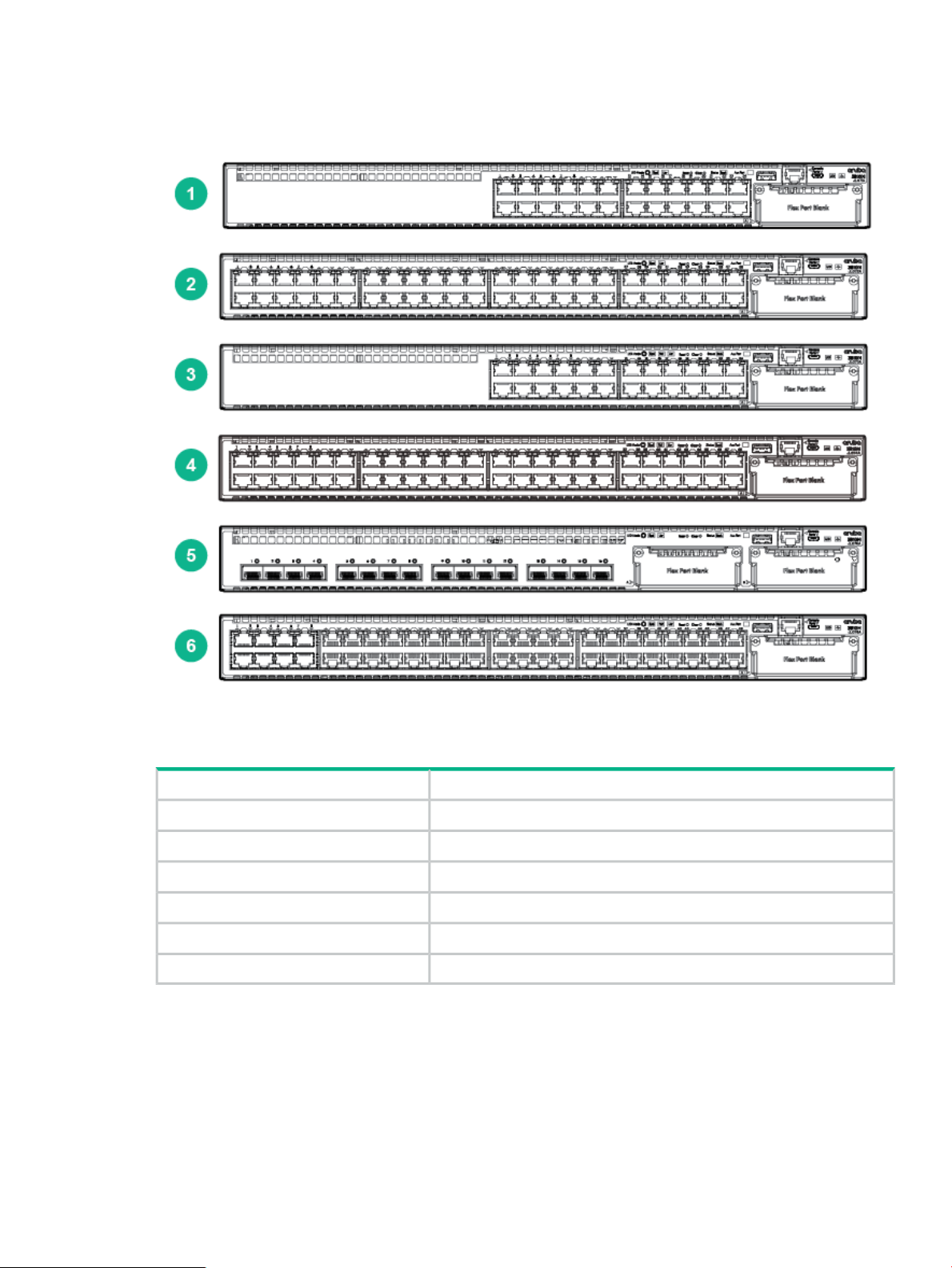
Front of the Switches
Figure 1 Front of all the 3810M Switches
Table 1 Front of all the 3810M Switches Label and Description
DescriptionLabel
Aruba 3810M 24G 1-slot Switch (JL071A)1
Aruba 3810M 48G 1-slot Switch (JL072A)2
Aruba 3810M 24G PoE+ 1-slot Switch (JL073A)3
Aruba 3810M 48G PoE+ 1-slot Switch (JL074A)4
Aruba 3810M 16SFP+ 2-slot Switch (JL075A)5
Aruba 3810M 40G 8 HPE Smart Rate PoE+ 1-slot Switch (JL076A)6
Front of the Switches 7
Page 8
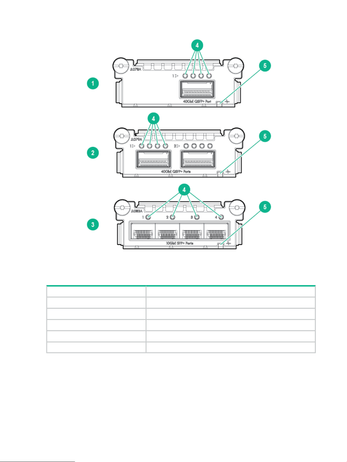
Figure 2 Front of 3810M Flex Port Modules
Table 2 3810M Flex Port Modules Label and Description
8 Introducing the 3810M switches
DescriptionLabel
Aruba 3810M 1QSFP+ 40GbE Module (JL078A)1
Aruba 3810M 2QSFP+ 40GbE Module (JL079A)2
Aruba 3810M 4SFP+ Module (JL083A)3
Port LEDs4
Flex Port Module Status LED5
Page 9
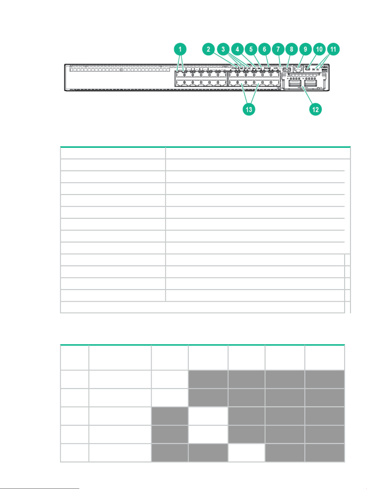
Figure 3 Example of 3810M Switches
Table 3 3810M Switches Labels and Description
Switch Port LEDs1
LED Mode button2
Speed, PoE*, Usr LEDs3
Reset, Clear buttons4, 5
DescriptionLabel
* PoE Mode LED is present only on switch models that support PoE.
Network Ports
Table 4 Network Ports
Product
number
JL071A
Model name
Aruba 3810M 24G 1-slot
Switch
Back Module Status LED6
Aux port status LED7
USB/Auxiliary Port8
RJ Serial Console9
Micro USB Console10
Global Status, Unit Identification LEDs11
Flex port Module expansion slot12
10/100/1000Base-T RJ-45 Ports13
10/100/1000
non-PoE
RJ-45 ports
24
10/100/1000
PoE/PoE+
1
RJ-45 ports
SFP+ Ports
1
2
40GSmartRate
JL072A
JL073A
JL074A
JL075A
Aruba 3810M 48G 1-slot
Switch
Aruba 3810M 24G PoE+
1-slot Switch
Aruba 3810M 48G PoE+
1-slot Switch
Aruba 3810M 16SFP+
2-slot Switch
48
24
48
16
Front of the Switches 9
Page 10
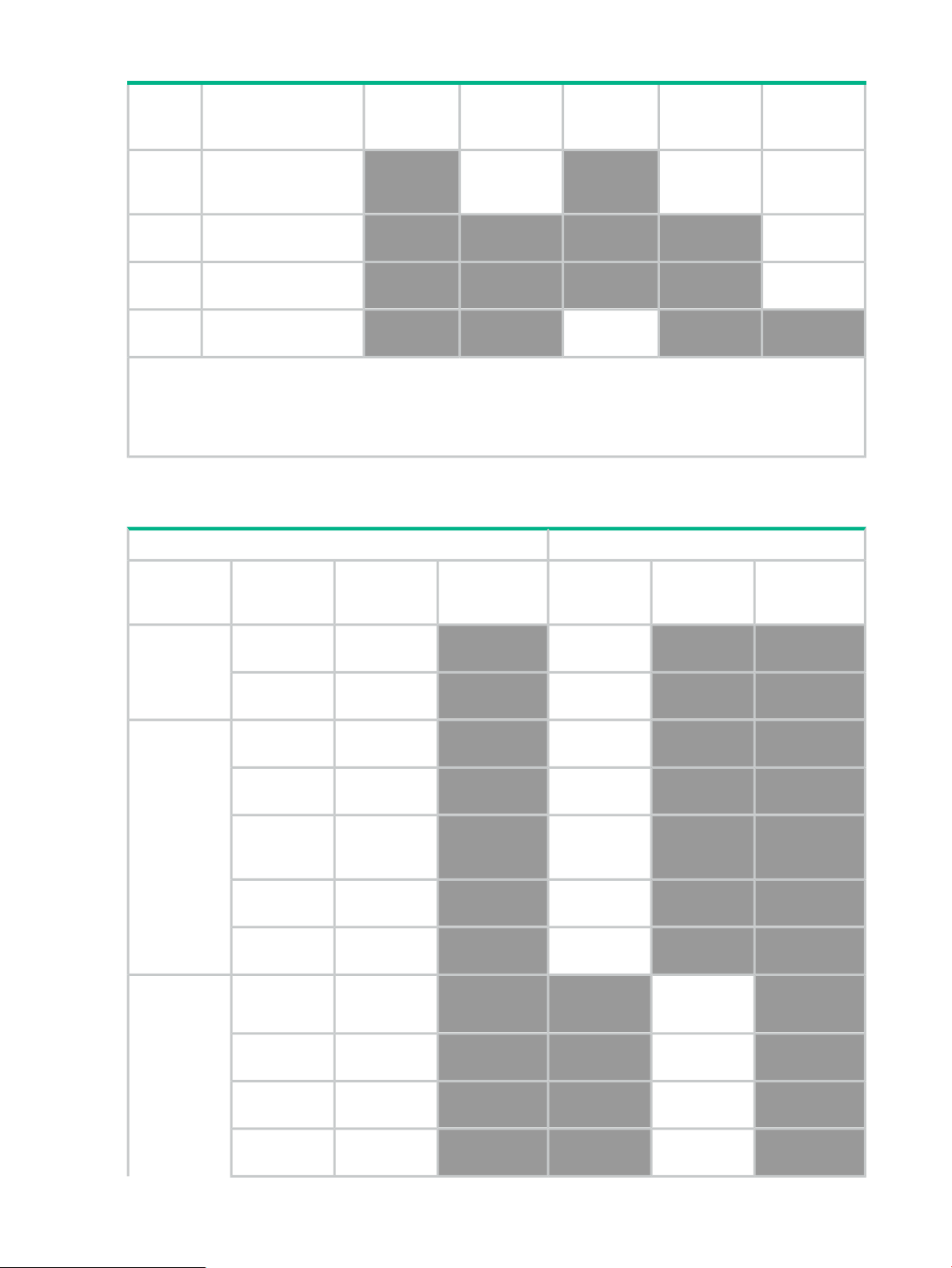
Table 4 Network Ports (continued)
Product
number
Model name
10/100/1000
non-PoE
RJ-45 ports
10/100/1000
PoE/PoE+
1
RJ-45 ports
SFP+ Ports
1
2
40GSmartRate
Aruba 3810M 40G 8
JL076A
HPE Smart Rate PoE+
840
1-slot Switch
JL078A
JL079A
JL083A
Aruba 3810M 1QSFP+
40GbE module
Aruba 3810M 2QSFP+
40GbE module
Aruba 3810M 4SFP+
module
4
1
2
Notes:
1
All RJ-45 ports support “Auto-MDIX”, which means you can use either straight-through or crossover twisted-pair
cables to connect network devices to the switch.
2
SFP+ ports support 100Mb (100-FX and 100-BX), 1G SFP and 10G SFP+ transceivers.
These products also support optional network connectivity:
Table 5 Optional Network Connectivity, Speeds and Technologies
Transceiver Form-Factor and Connector
1
100 Mbps
1 Gbps
100-FX
100-BX
1000-T
1000-SX
1000-LX
1000-LH
1000-BX
10-Gig
Direct Attach
CablingTechnologySpeed
Fiber
(multimode)
Fiber (single
mode)
Copper
(twisted-pair)
Fiber
(multimode)
Fiber
(multimode or
single mode)
Fiber (single
mode)
Fiber (single
mode)
Copper
(twinaxial)
Flex Module
Connector
SFP
("mini-GBIC")
Connector
LC
LC
RJ-45
LC
LC
LC
LC
QSFP+ConnectorSFP+Connector
Not
Applicable
10-Gig SR
10 Gbps
10-Gig LRM
10-Gig LR
10 Introducing the 3810M switches
Fiber
(multimode)
Fiber
(multimode)
Fiber (single
mode)
LC
LC
LC
Page 11

Table 5 Optional Network Connectivity, Speeds and Technologies (continued)
10-Gig ER
40-Gig Direct
Attach 1/3/5 m
40-Gig SR4
40 Gbps
40-Gig ESR4
40-Gig LR4
Smart Rate
1/2.5/5/10
Gbps
1
For supported transceivers, visit http://www.hpe.com/networking/support .
• In the first textbox, type J4858 (for 100-Mb and Gigabit information), J8436 (for 10-Gigabit information), or JH231
(for 40–Gigabit information).
• Select any of the products that display in the dropdown list.
• Select Support Center. Then click on Manuals, followed by View All to and find the Transceiver Support
Matrix.
For technical details of cabling and technologies, see Cabling and Technology Information.
Smart Rate
Fiber (single
mode)
Copper
(twinaxial)
Fiber
(multimode)
Fiber
(multimode)
Fiber (single
mode)
Copper
(twisted pair)
Not Applicable
MPO
MPO
LC
RJ-45
Management Ports
Console Ports
There are two serial console port options on the switch, an RJ-45 or Micro USB. These ports are
used to connect a console to the switch either by using the RJ-45 serial cable supplied with the
switch, or a standard Micro USB cable (not supplied). The Micro USB connector has precedence
for input, so if both cables are plugged in, the console output is echoed to both the RJ and
Micro-USB ports. But, the input is only accepted from the Micro-USB.
For more information on the console connection, see “10. (Optional) Connect a Management
console” (page 44). The console can be a PC or workstation running a VT-100 terminal emulator,
or a VT-100 terminal.
Auxiliary (Aux) Port
An auxiliary port for processing a USB command file or downloading switch software code. This
port uses a USB Type A connector, but does not comply with all USB protocols and standards.
Switch and Port LEDs on Front of the switches
• Front of Switch Status and Mode LED Behavior describes the switch chassis and Flex Port
status LEDs and also the Switch Mode LEDs.
• Table 9 (page 15) describes the switch Port LEDs and their different mode behaviors.
Front of the Switches 11
Page 12
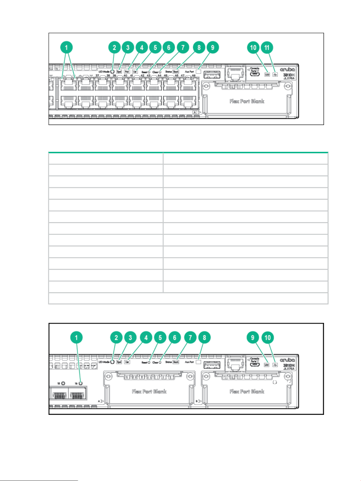
Figure 4 Switch and Port LEDs for JL071A, JL072A, JL073A*, JL074A*, and JL076A*
Table 6 Switch and Port LEDs Label and Description for JL071A, JL072A, JL073A*, JL074A*,
and JL076A*
DescriptionLabel
Switch Port LEDs1
LED Mode button2
Speed LED3
PoE LED*4
Usr LED5
Reset button6
Clear button7
Back Module status LED8
Aux Port status LED9
Unit Indentification LED10
Global status LED11
* PoE LED is present only on PoE switches.
Figure 5 Switch and Port LEDs for JL075A
12 Introducing the 3810M switches
Page 13

Table 7 Switch and Port LEDs Label and Description for JL075A
DescriptionLabel
Switch Port LEDs1
LED Mode button2
Speed LED3
Usr LED4
Reset button5
Clear button6
Back Module status LED7
Aux Port status LED8
Unit Identification LED9
Global status LED10
Table 8 Front of Switch Status and Mode LED Behavior
MeaningStateFunctionSwitch LEDs
Global Status
UID (Unit Identification)
the switch.
Self-Test Status
Switch/Port Fault Status
is used to help you to
a rack or collection of
products.
On GreenInternal Power Status of
Slow Flash Green*
Slow Flash Orange*
On Orange
On or Slow Flash**The Unit Identification LED
The Switch has passed self-test
and is powered up normally.
The switch self-test and
initialization are in progress
after the switch has been power
cycled or reset. The switch is
not operational until this LED
stops blinking green.
A fault or self-test failure has
occurred on the switch, one of
the switch ports, a module in
the rear of the switch, or the
fan. The Status LED for the
component with the fault will
blink simultaneously.
If this LED is on orange for a
prolonged time, the switch has
encountered a fatal hardware
failure, or has failed its self-test.
The unit is not receiving power.Off
The “chassislocate” command
allows you to blink or turn on
the LED for a specified numberidentify a particular unit in
of minutes (1-1440). The default
is 30 minutes.
Back Module Status
components installed in
the back of the unit.
Off
On GreenStatus of modular
Slow Flash Orange*
LED will turn off after the
timeout period has expired.
Normal operation: All modular
components installed in the
back of the unit are functioning
correctly.
One of the modules inserted
from the back of the chassis
(power supply, fan tray, or
Front of the Switches 13
Page 14

Table 8 Front of Switch Status and Mode LED Behavior (continued)
stacking module) has failed self
test or is experiencing a fault
condition. Flashes
simultaneously with the Global
Status LED flashing orange.
MeaningStateFunctionSwitch LEDs
Aux Port Activity
Flex Port Module Status
the Aux Port which is used
for processing a USB
command file or
downloading switch
software code.
module.
Solid GreenIndicates data transfer on
Green Flicker
Slow Flash Orange*
On GreenStatus of Flex Port
Slow Flash Orange*
Fast Flash Orange**
USB installed and successfully
initialized, and mounted, but no
data transfer.
Data transfer is in progress. Do
not remove installed device until
data transfer is complete
The USB device that is installed
is unsupported or faulted.
No USB installed.Off
Flex Port module operating
correctly.
Flex Port module has
experienced a fault.
The Global Status LED should
be flashing synchronously.
Flex Port module or one or
more of its ports is/are
experiencing an alert condition.
Alert conditions include that an
unsupported cable has been
installed in the module or that
the Flex Port module has been
installed while the switch was
powered on (hot-swapped) and
the switch needs to be rebooted
to support the module.
Speed Mode Selected
Power over Ethernet (PoE)
Mode Selected***
14 Introducing the 3810M switches
LEDs are showing port
speed information.
LEDs are showing PoE
status information.
OnIndicates when the Port
On GreenIndicates when the Port
On Orange
Slow Flash Orange*
No power.Off
No ModuleNo Present
Speed Mode is selected. Port
LEDs indicate port speed.
Speed mode not selected.Off
PoE Mode is selected. Port
LEDs show PoE information.
PoE Mode is selected and a
port also has a PoE error. The
Global Status LED and the LED
corresponding to the port with
the error will be flashing orange.
The rest of the Port LEDs will
display normal PoE status.
PoE Mode has NOT been
selected and a port has a PoE
error. LED will be flashing
orange simultaneously with the
Global Status LED and the LED
corresponding to the port with
Page 15

Table 8 Front of Switch Status and Mode LED Behavior (continued)
the error. The rest of the Port
LEDs will display normal PoE
status.
PoE mode is not selected.Off
MeaningStateFunctionSwitch LEDs
User Mode Selected
the Port LEDs are
displaying stack
information and status.
See Port LEDs and Mode
Behavior. When stacking
is disabled, this mode is
reserved for future use.
Save Power Mode Selected
* The slow blink behavior is an on/off cycle once every 1.6 seconds, approximately.
** The fast blink behavior is an on/off cycle once every 0.5 seconds, approximately.
*** Applies only to 3810M switches that support PoE/PoE+.
This mode is indicated by ALL the switch indicator LEDs
being off, except for the Global Status LED. This display
occurs only if the switch has been configured with the
savepower led command. See the Management and
Configuration Guide for more information on that command
Table 9 Port LEDs and Mode Behavior
Port LEDs
for the port as selected by
the LED Mode select
button.
When transceivers and
SFPs are installed, this LED
is also used to indicate that
the installation has occurred
by going on for two seconds
then off.
Activity/LinkTo display the information
User Mode is selected.On GreenWhen stacking is enabled,
User mode not selected.Off
MeaningState/ModeFunctionSwitch LEDs
Shows port Activity and Link
status.
This is the DEFAULT. There
is no dedicated mode LED
indicating this mode.
The Mode LED function
should return to this
selection 10 minutes after
the last press of the LED
Mode button.
Activity/Link Mode Selected
Link status and network
activity information
simultaneously.
Activity/Link Mode is the
default mode and is in effect
unless another LED mode
has been selected.
Speed
User
Half-Bright GreenPort LEDs are displaying
Activity Flicker Green
Shows port speed
configuration.
Shows PoE information.PoE
Shows User selectable User
behavior.
The port is enabled and
receiving a Link indication
from the connected device.
The percentage of time that
the LED is full-bright is
roughly proportional to the
percentage of full bandwidth
utilization of the port.
Half-Bright Green port Link
indication remains on as
Activity flickers from
half-bright to full-bright.
Front of the Switches 15
Page 16

Table 9 Port LEDs and Mode Behavior (continued)
MeaningState/ModeFunctionSwitch LEDs
Speed Mode Selected
the connection speed at
which each port is
operating.
Slow Flash Orange*
Off
Fast Flash Green**Port LEDs are displaying
On Green
Triple Blink Green
Double Blink Green
Slow Flash Green*
Off
The corresponding port has
failed its self-test. Flashes
simultaneously with the
Global Status LED flashing
orange.
The Port is disabled, not
connected, or not receiving
link.
The port is operating at 40
Gbps.
The port is operating at 10
Gbps.
The port is operating at 5
Gbps. (HPE SMART RATE
ports only)
The port is operating at 2.5
Gbps. (HPE SMART RATE
ports only)
The port is operating at 1
Gbps.
The port is not Linked, or is
operating at 10 or 100
Mbps.
PoE Mode Selected
User Mode Selected
PoE information.
in stacked configurations.
Used to display the number
of members in a stack and
their current status.
The status information is
sticky and if a unit’s status
changes while in USER
mode, you must exit and
re-enter USER mode to get
the updated status.
On GreenPort LEDs are displaying
Fast Flash Orange**
Slow Flash Orange*
Off
On GreenMode currently active only
Slow Flash Green*
Fast Flash Green**
On Orange
The port is providing PoE
power.
PoE is disabled on the port.On Orange
The port is denied power or
is detecting an external PD
fault.
The port has an internal
hardware failure. Flashes
simultaneously with the
Global Status LED flashing
orange.
The port is not providing
PoE power.
Stack Member exists in the
stack and is operational.
Indicates the Member # of
the chassis.
Indicates the Member # of
the Commander of the
stack.
Stack Member is currently
booting or has a fault that is
preventing it from
communicating.
16 Introducing the 3810M switches
Page 17

Table 9 Port LEDs and Mode Behavior (continued)
MeaningState/ModeFunctionSwitch LEDs
Slow Flash Orange*
Fast Flash Orange**
Off
* The slow blink behavior is an on/off cycle once every 1.6 seconds, approximately.
** The fast blink behavior is an on/off cycle once every 0.5 seconds, approximately.
*** Applies only to 3810M switches that support PoE/PoE+.
Stack Member is in a known
fault condition (i.e. Fan fault,
PSU fault, etc.).
The Global Status LED on
all stack members will also
Slow Flash Orange.
Stack Member is in a Alert
condition (i.e. Overtemp,
PoE Over subscript, etc.).
The Global Status LEDs on
all stack members will
remain in normal
operational.
Stack Member does not
exist in the stack
configuration.
Front of the Switches 17
Page 18

Example 1 Example of USER mode behavior
Assume you have a 4-member stack, in a ring topology, with member numbers 1, 2, 3 and 5.
Member 1 is the commander and member 3 is rebooting. In USER mode, the members will show
the following on their port LEDs:
Port 6-10 LEDsPort 5 LEDPort 4 LEDPort 3 LEDPort 2 LEDPort 1 LED
Member 1
Member 2
Member 5
Green
Fast Flash
Green
Going through normal boot up sequencingMember 3
Green
Green
OffOn OrangeOn GreenFast Flash
Green
OffOn GreenOffOn OrangeOn GreenFast Flash
OffOn GreenOffOn OrangeSlow Flash
OffSlow Flash
Looking at any member, you can see that there are 4 members defined in the stack configuration,
with member numbers 1, 2, 3, and 5 because these are the LEDs that are lit. The port 4 LED is
off, indicating that this member number is not defined in the stack.
On all members, Port 1 LED is fast flashing, indicating that member 1 is the commander of the
stack. Port 3 LED is on orange, indicating either that 3 is rebooting or not communicating because
of an unknown fault.
When looking at member 1, only Port 1 LED is fast flashing green. This indicates that this unit
is member 1 and is the commander.
When looking at member 2, the port 2 LED is slow flashing green, indicating that unit is member
number 2. Likewise on member 5, the port 5 LED is slow flashing green, indicating that unit is
member 5.
Member 3 will be going through the normal boot LED boot up sequence. When it has completed
booting and joined the stack, if you exit and re-enter USER mode, the members show the following
on their port LEDs:
Member 1
Green
Member 2
Member 3
Member 5
Fast Flash
Green
Green
Green
Green
On GreenFast Flash
Green
LED Mode Select Button and Indicator LEDs
The state of the Mode LEDs is controlled by the LED Mode select button. The current view mode
is indicated by the Mode LEDs next to the button. Press the button to step from one view mode
to the next. See the LED information in Front of Switch Status and Mode LED Behavior for
standalone switches.
Port 6-10 LEDsPort 5 LEDPort 4 LEDPort 3 LEDPort 2 LEDPort 1 LED
OffOn GreenOffOn GreenOn GreenFast Flash
OffOn GreenOffOn GreenSlow Flash
OffOn GreenOffSlow Flash
OffOn GreenOn GreenFast Flash
Green
OffSlow Flash
18 Introducing the 3810M switches
Page 19

Stacking Notes:
• For 3810M switches that are in a stack, the Mode select button on every switch in the stack
controls the LED mode for all the switches in the stack. Using the Mode select button on
one switch in the stack changes the LED mode for the entire stack.
• If there is a combination of PoE/PoE+ switches and non-PoE switches in the stack, when
any of the Mode select buttons is pressed to put the stack into PoE mode, the non-PoE
switches indicate no PoE support by not illuminating any of the Mode indicator LEDs or any
of the port LEDs.
• If any of the switches in the stack are configured with the Save Power LED feature, then
the default LED Mode for the whole stack becomes the Save Power display (all LED Mode
indicator LEDs are off), but only the stack members on which that feature is configured
display the other characteristics of that feature (all LEDs Off except for the Power LED).
Reset and Clear Buttons
The Reset and Clear buttons are recessed from the front panel (to protect them from being
pushed accidentally) and are accessible through small holes on the top of the front panel. Use
pointed objects, such as unbent paper clips, to push them.
The Reset and Clear buttons are used singly or in combination, as follows:
This will happen:Do this:To accomplish this:
(Standalone switch)
Hard Reset
(Standalone switch)
(Stacked switch)
Hard Reset
(Stacked switch)
Delete console and management
access passwords
Press and release the Reset buttonSoft Reset
Press and hold the Reset button for
more than 5 seconds (until all LEDs
turn on), then release.
more than 5 seconds (until all LEDs
turn on), then release.
Press Clear button for more than 5
seconds, but within 15 seconds (in
btw 5 - 15 seconds)
The switch operating system is cleared
gracefully (such as data transfer
completion, temporary error conditions
are cleared), then reboots and runs
self tests.
The switch reboots, similar to a power
cycle. A hard reset is used, for
example, when the switch CPU is in
an unknown state or not responding.
Same as a standalone switch, except:Press and release the Reset buttonSoft Reset
• If action happened on the
Commander, the Standby switch
will become Commander.
• If action happened on the Standby,
a new Standby will be elected.
Same as a standalone switch, except:Press and hold the Reset button for
• If action happened on the
Commander, the Standby switch
will become Commander.
• If action happened on the Standby,
a new Standby will be elected.
Clears all passwords. Will flash Global
Status Green LED, after 5 seconds has
expired to indicate passwords have
cleared.
Turn off UID LED
Clears the UID LED.Press Clear button and release within
5 seconds (in btw 0.5 - 5 seconds)
Front of the Switches 19
Page 20

This will happen:Do this:To accomplish this:
Restore the factory default
configuration
Note: These buttons are provided for your convenience. If you are concerned with switch security though, you should
make sure that the switch is installed in a secure location, such as a locked wiring closet. You can also disable these
buttons by using the front-panel-security command. See the 3810M Management and Configuration Guide for a
description of that command.
1. Press Clear and Reset
simultaneously.
2. While continuing to press Clear,
release Reset.
3. When the Global Status LED
begins to fast flash orange (after
approximately 5 seconds), release
Clear.
Flex Port Slot and Module Support
The 3810M family of switches features a module slot(s) that allows the user to customize the
uplink ports on the switch. Depending on the switch model, the slot supports either 40Gbps or
80Gbps of maximum bandwidth and therefore, not all modules are supported in all slots. See
Switch Module/Support Matrix, for the switch module/support matrix.
NOTE: The unsupported modules are mechanically prevented from installing into unsupported
slots.
Table 10 Switch Module/Support Matrix
The switch removes all configuration
changes, restores the factory default
configuration, and runs self test.
JL071A Aruba 3810M 24G 1-slot
Switch
JL072A Aruba 3810M 48G 1-slot
Switch
JL073A Aruba 3810M 24G PoE+
1-slot Switch
JL074A Aruba 3810M 48G PoE+
1-slot Switch
JL075A Aruba 3810M 16SFP+ 2-slot
Switch
JL076A Aruba 3810M 40G 8SR PoE+
1-slot Switch
Back of the Switches
The back of all the 3810M switches is the same.
Module Support
JL083A 4SFP+JL079A 2QSFP+JL078A 1QSFP+Switch Model
YesNoYes
YesYesYes
YesNoYes
YesYesYes
YesNoYes
YesYesYes
20 Introducing the 3810M switches
Page 21
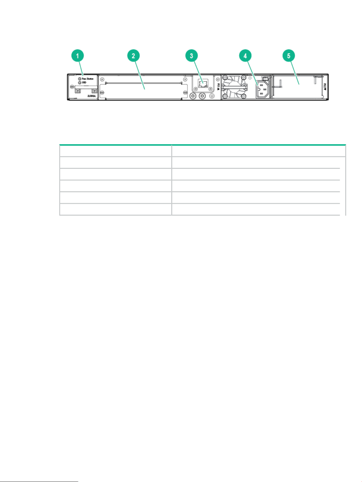
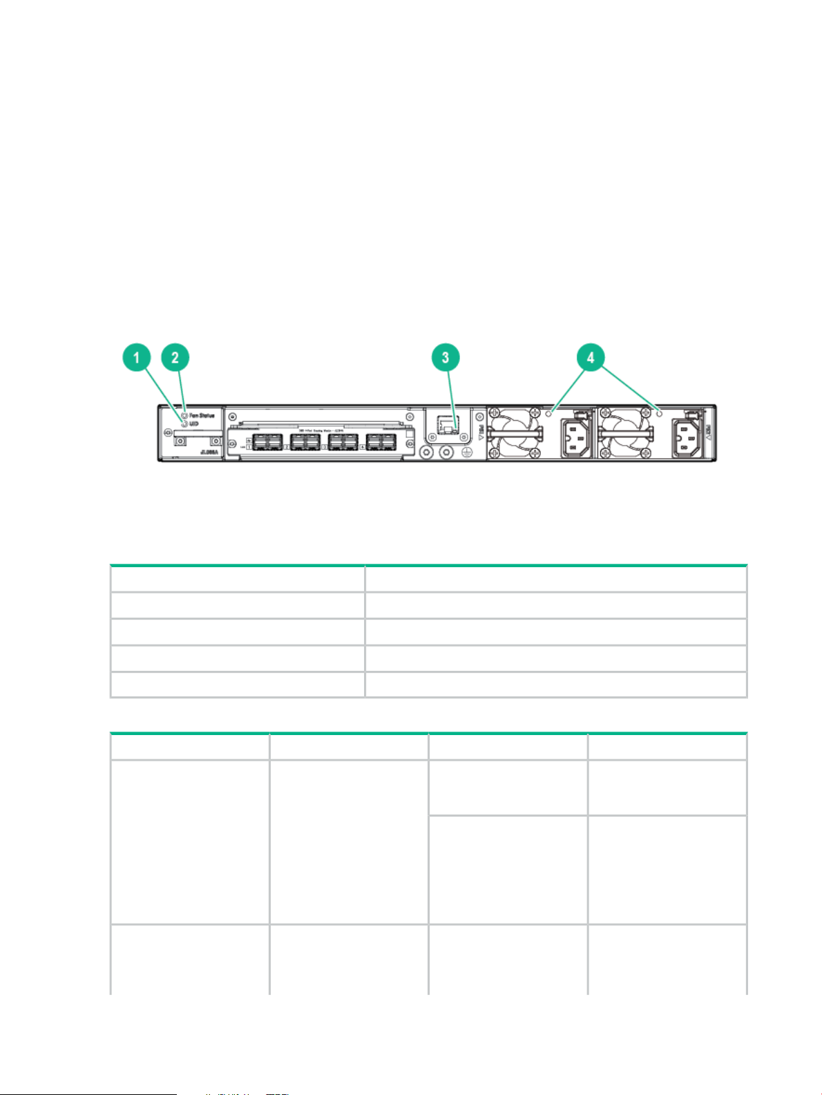
Figure 6 Back of the 3810M Switches
Table 11 Back of the 3810M Switches Label and Description
DescriptionLabel
Fan Status LED1
Stacking Module Slot2
Management/OOBM port3
AC Power connector/Power Supply slot 14
Power Supplies
There are three power supplies that can be installed into the 3810M switches:
• Aruba X371 12VDC 250W 100-240VAC Power Supply (JL085A)—A 250 watt power supply
for the non-PoE switches. This power supply does not provide any PoE power, and is keyed
so that it will not fit into the power supply slots of 3810M PoE+ switches.
• Aruba X372 54VDC 680W 100-240VAC Power Supply (JL086A)—A 680 watt power supply
for 3810M PoE+ supported switches. This power supply offers up to 370 watts of PoE+
power, and is keyed so that it does not fit into the power supply slots of non-PoE+ 3810M
switches.
• Aruba X372 54VDC 1050W 110-240VAC Power Supply (JL087A)—A 1050 watt power
supply for 3810M PoE+ supported switches. This power supply offers up to 740 watts of
PoE+ power, and is keyed so that it does not fit into the power supply slots of non-PoE+
3810M switches.
For more power supply information see 9. (Optional) Installing a Second Power Supply.
Power Connector
The 3810M switches do not have a power switch. They will power on when either one or both
power supplies are connected to an active AC power source.
Redundant Power Supply slot 25
Stacking Module Slot
Each of the 3810M switches has one module slot that can accept the 3810M Stacking Module
that provides high-speed connectivity to other 3810M switches. Only the 3810M switches support
this module.
Back of the Switches 21
Page 22
Fan Tray Assembly
The 3810M switches have a field-replaceable fan tray. If necessary, the fan tray can be replaced
while the switch is operating. For more information, see Replacing the Fan Tray.
Out-of-Band Management (OOBM) Port
This RJ-45 port is used to connect a dedicated management network to the switch.
LEDs on the Back of the Switches
This section describes the LEDs on the back of the switch. When the Back LED on the front of
the unit is blinking a fault, the user can then look at the back of the switch to find the corresponding
blinking LED for the faulted module.
Figure 7 LEDs on the Back of Switches
Table 12 Back of the 3810M Switches LED Labels and Description
DescriptionLabel
Unit Identification LED1
Fan Status LED2
OOBM Port LED: Activity/Link3
Power Supply Status LEDs4
Table 13 LEDs on the Back of the Switch
On GreenStatus of Fan tray.Fan Status
Slow Flash Orange
Unit Identification
identify a particular unit in a
rack or collection of
products.
On or Slow FlashUsed to assist you to
MeaningStateFunctionSwitch LEDs
Normal operation: Fan tray
assembly is functioning
correctly.
One or more fans in the fan
tray is faulted.
The Global Status and Back
LEDs on the front of unit
must also be synchronized
and flashing orange.
The chassislocate
command allows you to
blink or turn on the LED for
a specified number of
22 Introducing the 3810M switches
Page 23

Table 13 LEDs on the Back of the Switch (continued)
MeaningStateFunctionSwitch LEDs
OOBM Port LED:
Activity/Link
This LED is a copy of the
UID LED on the front of the
chassis.
port status of OOBM
Off
Half-Bright GreenDisplay Activity/Link and
On Green
Activity Flicker Green
Slow Flash Orange
minutes (1-1440). The
default is 30 minutes.
The LED turns off after the
timeout period has expired.
The port is enabled and
receiving a Link indication
from the connected device.
The port is experiencing
high bandwidth utilization.
The percentage of time that
the LED is full-bright is
roughly proportional to the
percentage of full bandwidth
utilization of the port. Even
just one packet will trigger
a visible full-bright flicker.
Half-Bright Green port Link
indication remains on as
Activity flickers from
half-bright to full-bright.
The port has failed its
self-test. Flashes
simultaneously with the
Global Status LED flashing
orange.
PSU module Status
Looking at the back of the
unit, PSU1 is on the left and
PSU2 is on the right.
3810M Stacking Module
The 3810M 4-port Stacking Module (JL084A) is a component you can add to an 3810M Switch
to provide high-speed stacking connections to other 3810M switches. See Stacking Information
and Topologies, and the HPE ArubaOS-Switch Advanced Traffic Management Guide
K/KA/KB.16.01 for more information about stacking configuration and operation.
Off
On GreenStatus of PSU
Slow Flash Green
Off
The port is disabled, not
connected, or not receiving
link.
The power supply has valid
AC input and valid DC
outputs.
Either the power supply has
an internal fault, or switch
has a fault that is causing
power supply to cycle on/off.
The power supply has an
invalid AC input, or invalid
DC outputs.
3810M Stacking Module 23
Page 24
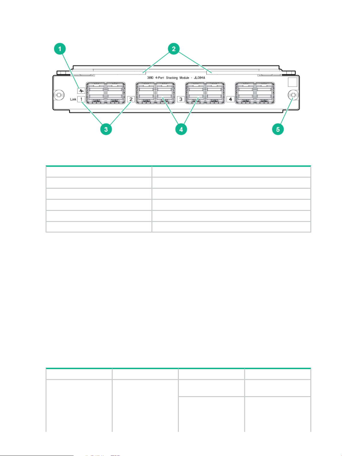
Figure 8 Front of 3810M 4-Port Stacking Module
Table 14 Front of 3810M 4-Port Stacking Module Label and Description
DescriptionLabel
Stacking Module Status LED1
The 3810M 4-Port Stacking Module JL084A has the following features:
• Four stacking connectors for connecting the 3810M switch to other 3810Ms in a stacked
topology (chain, ring, or mesh). Any of these available stacking cables can be used for these
connections:
◦ Aruba 3800/3810M 0.5m Stacking Cable (J9578A)
◦ Aruba 3800/3810M 3m Stacking Cable (J9579A)
◦ Aruba 3800/3810M 1m Stacking Cable (J9665A)
• LEDs, described in Table 15.
Stacking Module LEDs
The following LEDs are located on the 3810M Stacking Module itself and are only viewable from
the rear of the switch.
Extractor Handles2
Link LEDs3
Stacking Connectors4
Retaining Screw5
Table 15 Stacking Module LEDs
24 Introducing the 3810M switches
On GreenStatus of Stacking moduleStacking Module Status
Slow Flash Orange
DescriptionModeFunctionName
Stacking module operating
correctly.
Stacking module has
experienced a fault, or one
or more of the module ports
has experienced a fault. The
1.6 seconds cycle flash
Page 25

Table 15 Stacking Module LEDs (continued)
DescriptionModeFunctionName
should be synchronized with
the switch Global Status
LED. The Global Status and
Back LED should also be
flashing.
Stacking Link Status
port indicates the port is
enabled, connected and
detects a signal from the
attached device.
Fast Flash Orange
On GreenThe Link LED per stacking
Slow Flash Orange
Stacking module or one or
more of its ports is
experiencing an alert
condition.
Alert conditions include that
an unsupported cable has
been installed in the module
or that the stacking module
has been installed while the
switch was powered on
(hot-swapped) and the
switch needs to be rebooted
to support the module.
The BACK LED should be
flashing and the Global
Status LED should NOT be
flashing.
No PowerOff
The port is enabled and
receiving a link indication
from the connected device.
Port Failed POST or cable
fault. Module Status LED on
the stacking module and
Global Status and Back
LED on front of unit should
also be synchronized and
flashing orange.
Switch Features
The features of the 3810M switches include:
• Combinations of fixed 10/100/1000-T, HPE SMART RATE and SFP/SFP+ ports, as described
under Network Ports.
• Selected switch models feature HPE SMART RATE ports and provide 1Gbps, 2.5Gbps,
5Gbps and 10Gbs connectivity. See the appendices for cabling recommendations and
requirements.
• All switch models feature either 1 or 2 Flex Port Module slots, that allow configuration with
either 10G SFP+ or 40G QSFP+ ports, as described in Flex Port Slot and Module Support.
• One module slot is provided in the back of the switches to support a stacking module to
provide connectivity to other 3810M switches with stacking modules. See Stacking
Information and Topologies, the HPE ArubaOS-Switch Advanced Traffic Management Guide
K/KA/KB.16.01 for more information about stacking.
• Power over Ethernet (PoE+) operation—Aruba 3810M 24G PoE+ 1-slot Switch (JL073A),
Aruba 3810M 48G PoE+ 1-slot Switch (JL074A) and Aruba 3810M 40G 8 HPE Smart Rate
PoE+ 1-slot Switch (JL076A) switches are IEEE 802.3at standard compliant and provide up
No cable plugged in.Off
Switch Features 25
Page 26

to 30W per port to power IP phones, wireless access points, indoor web cameras, and more.
For more information, see the HPE Power over Ethernet (PoE/PoE+) Planning and
Implementation Guide, available from http://www.hpe.com/networking/support.
The switches support 802.3af and 802.3at standard devices and some pre-standard PoE
devices. For a list of these devices, see the FAQs (Frequently Asked Questions) for your
switch model. PoE is enabled by default. (For instructions, see the 3810M Management and
Configuration Guide for your switch at http://www.hpe.com/networking/support.
• The option to have one or two internal power supplies.
A second power supply supports redundant system power and/or redundant/additional PoE
power. If one of the internal power supplies fails, the second power supply immediately
provides the power necessary to keep the switch running, including PoE+ power on an
allocated basis.
If maximum PoE+ power is used on the 48 port PoE+ switch, the second power supply is
needed for PoE+ power but there is no PoE power redundancy. However, system power is
always maintained. On a power supply failure, the system drops the PoE power on ports
based on user priority, to maintain system power. For more information on Power Supplies,
see Power Supplies.
• Plug-and-play networking—all ports are enabled by default—just connect the network cables
to active network devices and your switched network is operational.
• Auto MDI/MDI-X on all twisted-pair ports (10/100/1000 and 10GBase-T), meaning that all
connections can be made using straight-through twisted-pair cables. Cross-over cables
are not required, although they will also work. The pin operation of each port is automatically
adjusted for the attached device: if the switch detects that another switch or hub is connected
to the port, it configures the port as MDI; if the switch detects that an end-node device is
connected to the port, it configures the port as MDI-X. (See the appendices for recommended
or required cabling.)
• Automatic learning of the network addresses in each switch’s 64000-address forwarding
table, (with configurable address aging value).
• Automatically negotiated full-duplex operation for the 10/100/1000 RJ-45 ports when
connected to other auto-negotiating devices—the SFP/SFP+ ports always operate at full
duplex.
• Easy management of the switch through several available interfaces:
Console interface—A full featured, easy to use, VT-100 terminal interface for
◦
out-of-band or in-band switch management.
◦ Web browser interface—An easy to use built-in graphical interface that can be accessed
from common web browsers.
◦ IMC—An SNMP-based, graphical network management tool that you can use to manage
your entire network.
• Support for the Spanning Tree Protocol to eliminate network loops.
• Support for up to 4096 IEEE 802.1Q-compliant VLANs so you can divide the attached end
nodes into logical groupings that fit your business needs.
• Support for many advanced features to enhance network performance—for a description,
see the 3810M Management and Configuration Guide at http://www.hpe.com/networking/
support.
• Ability to update the switch software. Software updates are routinely available from Hewlett
Packard Enterprise.
26 Introducing the 3810M switches
Page 27

• An auxiliary port (USB Type A connector) for processing a USB command file and updating
switch software.
• Low power operation:
◦ Ports on a switch or stack member may be set to operate at reduced power.
◦ Port status LEDs may be turned off.
◦ RJ-45 ports will operate at reduced power if the port is not connected (link partner is
not detected).
Switch Features 27
Page 28

2 Installing the Switch
This chapter shows how to install the switch. The 3810M switches come with an accessory kit
that includes the brackets for mounting the switch in a standard 19-inch telco rack, in an equipment
cabinet, and with rubber feet that can be attached so the switch can be securely located on a
horizontal surface. The brackets are designed to allow mounting the switch in a variety of locations
and orientations. For other mounting options contact your local Hewlett Packard Enterprise
authorized network reseller or Hewlett Packard Enterprise representative.
NOTE: If the switch is to be shipped in a rack, it can be mounted and shipped in a Hewlett
Packard Enterprise 10K rack using the HPE X410 Universal Rack Mounting Kit (J9583A).
Additionally, it can also be mounted in any four post rack using the HPE X410 Universal Rack
Mounting Kit (J9583A).
Included Parts
The 3810M switches have the following components shipped with them:
• Aruba Switch Quick Setup Guide
• Switch Safety and Regulatory sheet
• Warranty notice
• General Safety and Regulatory booklet
• Console cable
• Accessory kit
(5066-0651) for PoE+ 3810M switches(5069-5705) for Non-PoE+ 3810M switches
two mounting bracketstwo mounting brackets
eight 8-mm M4 screws to attach the mounting brackets
to the switch
four 5/8-inch number 12-24 screws to attach the switch
to a rack
eight 8-mm M4 screws to attach the mounting brackets
to the switch
four 5/8-inch number 12-24 screws to attach the switch
to a rack
four rubber feetfour rubber feet
• There are two warranty documents. One is HPN warranty and the other is EG warranty.
5998-8729 Warranty Statement and Software License◦
◦ 5998-8843 Aruba 3810M QSG/SRI
◦ 5998-8844 Read Me First
◦ 703828-026 EG Safety, Compliance, and Warranty Information
• Power cord, one of the following
28 Installing the Switch
Page 29
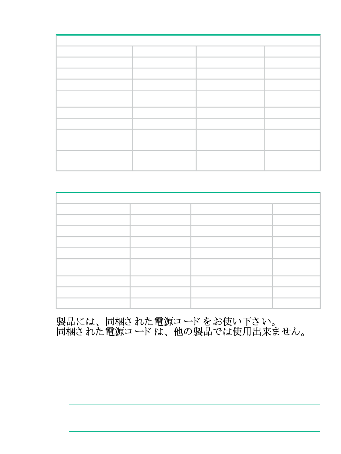
Power cord, one of the following:
Aruba 3810M PoE+ Switches
Kong/Singapore/Malaysia
Power cord, one of the following:
8121-0857Australia8121-0973North America
8121-1265Brazil8121-0941North America high line
8120-5336Europe/South Korea8121-1483South Africa/India
8121-1034China8121-1009Israel
8121-1481Argentina8120-5334United Kingdom/Hong
8120-8389Chile8120-5339Switzerland
8121-0671Thailand/Philippines8120-5340Danish
8121-1511Taiwan 15A8120-5338Japan high line
(JL086A, JL087A)(JL086A, JL087A)
8121-0967Taiwan 10A8120-5342Japan low line
(JL086A)(JL086A)
Aruba 3810M Non-PoE+ Switches
Korea
Installation Procedures
8120-4753Japan8120-6869Argentina
8120-6815Switzerland8121-0834Australia/New Zealand
8120-6813South Africa8121-1069Brazil
8121-0974Taiwan8120-6980Chile
8121-0668Philippines/Thailand8120-8707China
8120-6809UK/HongKong/Singapore/Malaysia8120-6811Continental Europe/South
8121-0973US/Canada/Mexico8120-6814Denmark
8121-0941North America high line8121-0780India
8121-1035Israel
Summary
1. Prepare the installation site (“ 1. Prepare the Installation Site” (page 31)). Ensure the
physical environment is properly prepared, including having the correct network cabling
ready to connect to the switch and having an appropriate location for the switch. See “
Installation Precautions:” (page 31) for some installation precautions.
NOTE: For steps 2 and 3 below, if an 3810M switch is powered on for the first time without
a stacking module installed, stacking will be disabled and that will be saved in the switch's
running configuration. For more information, see Stacking Information and Topologies.
Installation Procedures 29
Page 30

2. Verify the switch passes self test ( “ 2. Verify the Switch Boots Correctly” (page 32) ).
Plug the switch into a power source and observe that the LEDs on the switch’s front panel
indicate correct switch operation. When self test is complete, unplug the switch.
3. (Optional) Install the stacking module ( 3. (Optional) Install the Stacking Module).
4. (Optional) Install the Flex Port module (4. Installing the Flex Port Module).
5. Mount the switch ( “5. Mount the Switch” (page 37) ). The Switch can be mounted in the
19-inch telco rack, in an equipment cabinet, or on a horizontal surface.
6. (Optional) Install the stacking cables ( 6. (Optional) Installing the Stacking Cables). If
you have installed the module, you can now install up to four stacking cables and connect
them to other switches in the desired stacking topology.
7. (Optional) Install or remove SFP transceivers (mini-GBICs) (7. (Optional) Installing
Transceivers). Depending on the switch model purchased and optional Flex Port module
configuration, the switch can support SFP/SFP+ or QSFP+ transceivers. Depending on
where the switch is mounted, it may be easier to install the transceivers first. All transceiver
types can be installed or removed while the switch is powered on.
8. Connect the switch to a power source ( 8. Connect the Switch to a Power Source).
Once the switch is mounted, plug it into the nearby main power source.
9. (Optional) Install a second power supply ( 9. (Optional) Installing a Second Power
Supply). You may wish to use a second power supply with the switch to provide redundant
power or added PoE+ power.
10. (Optional) Connect a Management console (10. (Optional) Connect a Management
console). You may wish to modify the switch’s configuration, for example, to configure an
IP address so it can be managed using a web browser, from an SNMP network management
station, or through a Telnet session. Configuration changes can be made easily by using
the included console cable to connect a PC to the switch’s console port.
11. Connect the network cables (“ 11. Connect the Network Cables” (page 46)). Using the
appropriate network cables, connect the network devices to the switch ports.
At this point, the switch is fully installed. See the rest of this chapter if you need more detailed
information on any of these installation steps.
30 Installing the Switch
Page 31

Installation Precautions:
Follow these precautions when installing the 3810M switches.
WARNING!
• The rack or cabinet should be adequately secured to prevent it from becoming unstable
and/or falling over.
• Devices installed in a rack or cabinet should be mounted as low as possible, with the
heaviest devices at the bottom and progressively lighter devices installed above.
CAUTION:
• If the switch is to be shipped in a rack, it can be mounted and shipped in a Hewlett Packard
Enterprise 10K rack using the HPE X410 Universal Rack Mounting Kit (J9583A). Additionally,
it can be mounted in many 4-post racks using the HPE X410 Universal Rack Mounting Kit
(J9583A).
• Ensure the power source circuits are properly grounded, then use the power cord supplied
with the switch to connect it to the power source.
• If your installation requires a different power cord than the one supplied with the switch and
power supply, be sure the cord is adequately sized for the switch’s current requirements. In
addition, be sure to use a power cord displaying the mark of the safety agency that defines
the regulations for power cords in your country. The mark is your assurance that the power
cord can be used safely with the switch and power supply.
• When installing the switch, the AC outlet should be near the switch and should be easily
accessible in case the switch must be powered off.
• Ensure the switch does not overload the power circuits, wiring, and over-current protection.
To determine the possibility of overloading the supply circuits, add together the ampere
ratings of all devices installed on the same circuit as the switch and compare the total with
the rating limit for the circuit. The maximum ampere ratings are usually printed on the devices
near the AC power connectors.
• For safe operation, proper switch cooling, and reduction of electromagnetic emissions,
ensure that a slot cover is installed on any unused module or power supply slot.
• Do not install the switch in an environment where the operating ambient temperature might
exceed 45°C (113°F).
• Ensure the air flow around the sides and back of the switch is not restricted.
1. Prepare the Installation Site
Cabling Infrastructure - Ensure the cabling infrastructure meets the necessary network
specifications. See Cabling and Technology Information in the appendices for more information.
Installation Location - Before installing the switch, plan its location and orientation relative to
other devices and equipment:
• In the front of the switch, leave at least 7.6 cm (3 inches) of space for the twisted-pair and
fiber-optic cabling.
• In the back of the switch, leave at least 3.8 cm (1 1/2 inches) of space for the power cord.
If you are stacking the switches, you will need 20 to 23 cm (approximately 8 to 9 inches),
depending on the lengths of the stacking cables being used.
• On the sides of the switch, leave at least 7.6 cm (3 inches) for cooling, except if the switch
is installed in an open EIA/TIA rack.
Installation Procedures 31
Page 32

Figure 9 Air flow direction of the 3810M switches
2. Verify the Switch Boots Correctly
NOTE: For steps 2 and 3, if an 3810M switch is powered on for the first time without a stacking
module installed, stacking will be disabled and that will be saved in the switch's running
configuration. For more information, see Stacking Information and Topologies.
Before installing the switch in its network location, you should first verify it is working properly by
plugging it into a power source and verifying that it boots correctly.
32 Installing the Switch
Page 33

1. Connect the power cord supplied with the switch to the power connector on the back of the
switch, and then into a properly grounded electrical outlet.
Figure 10 Connecting the Power cord
NOTE: The 3810M switches do not have a power switch. They are powered on when the
power cord is connected to the switch and to a power source. For safety, the power outlet
should be located near the switch installation.
The switch automatically adjusts to any voltage between 100-240 (110–240 for JL087A
power supply) and either 50 or 60 Hz. No voltage range settings are required.
If your installation requires a different power cord than the one supplied with the switch, be
sure to use a power cord displaying the mark of the safety agency that defines the regulations
for power cords in your country. The mark is your assurance that the power cord can be
used safely with the switch.
2. Check the LEDs on the switch as described below.
Figure 11 Example of an 3810M-48-port PoE+ switch
Installation Procedures 33
Page 34

Table 16 Example of an 3810M-48-port PoE+ switch Label and Description
DescriptionLabel
Switch Port LEDs1
Mode LEDs2
When the switch is powered on, it performs its diagnostic self test and initialization. This boot
process, depending on switch model and configuration, takes approximately 1-2 minutes to
complete.
LED Behavior:
During the switch boot:
• The Global Status, UID, other Status and Mode LEDs, will initially turn on green and
bi-color LEDs will change to orange, then back to green.
• The Global Status LED will start blinking green, indicating the switch is going thru its self-test
and will continue to blink green until the switch if fully booted.
• The Port LEDs will come on green, turn orange, turn back to green, and then may blink on
and off during phases of the boot.
When the switch boots successfully, the LEDs display:
• Global Status and Back LEDs will be on solid green.
• Locator LED is off.
3
Back LED
Global Status and UID LEDs4
• Other status LEDs may be on or off depending on the switch configuration and the hardware
installed.
• The port LEDs go into their normal operational mode:
If the ports are connected to active network devices, the port LED may be on and
◦
behaves according to the LED mode selected. In the default LED mode (Activity/Link),
the LED should show half-bright green to indicate Link and be flickering full-bright green
to show network traffic.
◦ If the ports are not connected to active network devices, the port LED will stay off.
If the LED display is different than what is described above, especially if the Global Status LED
continues to blink green for more than 120 seconds or blinks orange continually, then the switch
boot has not completed correctly. Refer to “ Troubleshooting” (page 68) for diagnostic help.
3. (Optional) Install the Stacking Module
NOTE: Hot swapping the Stacking Module is not supported. If a module is installed with the
switch powered on, self-test of the module will not occur, the Back LED on the front of the switch
and the Module Status LED on the module will blink orange. The switch must be reset or power
cycled for the module to function. Only insert or remove a module during scheduled downtime
with the switch powered off.
1. Remove the cover plate.
2. Insert the module aligning with the guides in the slot.
3. Once the contacts have engaged, use the extractor handles to seat the module completely.
34 Installing the Switch
Page 35

4. Tighten the captive screws until they are snug – do not overtighten them.
Figure 12 Installing the Module
Verifying the Module is Installed Correctly
Observe the Back and Global Status LEDs on front of the switch, and the Module Status LED
on the module to verify module is installed properly.
Figure 13 Location of Module Status LEDs
Table 17 Location of Module Status LEDs Label and Description
DescriptionLabel
Back LED1
Global Status LED2
If the module is installed properly and the switch is powered on, the module undergoes a self
test during the normal switch boot up process. You can use the LEDs to determine that the
Installation Procedures 35
Page 36

module is installed properly and has passed the self test, as described in the “LED Behavior”
table Stacking Module LED Behavior.
Table 18 Stacking Module LED Behavior
Display for a Properly Installed ModuleLED
After boot-up sequencing, LEDs are on steady green.Global
Status and
Back LEDs
on front of
the switch
and Module
Status LED
on the
stacking
module
Link (for
each
stacking
port on the
module)
If stacking cables are connected to the module and to a Stacking Module on another powered on
3810M switch, the LED goes ON green to indicate the stacking port is enabled, connected, and detects
a signal from the attached switch.
4. Installing the Flex Port Module
1. Unscrew the two retaining screws on the blank filler and remove it.
2. Remove the new Flex Port module from its packaging, be careful not to touch any of the
circuitry on the board.
3. Insert the Flex Port module fully into the slot as shown in Install Flex Port Module. The face
plate of the module will be flush with the front face of the switch.
4. Engage the retaining screws and tighten them. Be sure, to not overtighten the screws.
5. Power on the switch and make sure the module passes its self test. See Flex Port LED Error
Indicators for the module LED behavior that indicates correct installation.
36 Installing the Switch
Page 37

Figure 14 Install Flex Port Module
5. Mount the Switch
After the switch passes self test, the switch is ready to be mounted in a stable location. The
3810M switches can be mounted in these ways:
• in a rack or cabinet
• on a horizontal surface
For other mounting options contact your local Hewlett Packard Enterprise authorized network
reseller or Hewlett Packard Enterprise representative.
Rack or Cabinet Mounting
These switches are designed to be mounted in any EIA-standard 2-post 19-inch telco rack or
4-post communication equipment cabinet.
WARNING! For safe operation, please read the mounting precautions on“ Installation
Precautions:” (page 31), before mounting a switch.
Equipment Cabinet Note:
The 12-24 screws supplied with the switch are the correct threading for standard EIA/TIA open
19-inch racks. If you are installing the switch in an equipment cabinet such as a server cabinet,
use the clips and screws that came with the cabinet in place of the 12-24 screws that are supplied
with the switch.
Complete step 1, and plan which four holes you will be using in the cabinet and install all four
clips. Then proceed to step 2.
Installation Procedures 37
Page 38

Rack Mounting the 3810M switch in a 2-post rack
1. Use a #1 Phillips (cross-head) screwdriver and attach the mounting brackets to the switch
with the included 8-mm M4 screws.
Figure 15 Attaching the mounting brackets to the switch
NOTE: The mounting brackets have multiple mounting holes and can be rotated allowing
for a wide variety of mounting options. These include mounting the switch so its front face
is flush with the face of the rack as shown in the illustration, or mounting it in a more balanced
position.
2. Hold the switch with attached brackets up to the rack and move it vertically until rack holes
line up with the bracket holes, then insert and tighten the four number 12-24 screws holding
the brackets to the rack.
Figure 16 Mounting the switch in a rack
38 Installing the Switch
Page 39

Rack Mounting the 3810M switch in a 4-post rack
1. Using the (J9583A) X410 E-Series 1U Universal Rack Mounting Kit, use a #1 Phillips
(cross-head) screwdriver and attach the slider brackets to the switch with the included 8-mm
M4 screws.
Figure 17 Attaching the rail kit slider brackets to the switch
2. Install the rails in the rack.
Figure 18 Installing the rails
3. Installing the switch into the rails.
Installation Procedures 39
Page 40

Figure 19 Installing the switch
4. Securing the switch in rack after installation.
Figure 20 Secure the switch
Horizontal Surface Mounting
Place the switch on a table or other horizontal surface. The switch comes with rubber feet in the
accessory kit that can be used to help keep the switch from sliding on the surface.
Attach the rubber feet to the four corners on the bottom of the switch within the embossed angled
lines. Use a sturdy surface in an uncluttered area. You may want to secure the networking cables
and switch power cord to the table leg or other part of the surface structure to help prevent tripping
over the cords.
CAUTION: Make sure the air flow is not restricted around the sides and back of the switch.
40 Installing the Switch
Page 41

6. (Optional) Installing the Stacking Cables
NOTE: Hot swapping stacking cables is supported. You can install or remove a stacking cable
with the switch powered on.
a. Slide in the stacking cable connector until it clicks into place. Pull on the cable connector (not
the tab) to make sure that it is fully latched.
Figure 21 Installing a stacking cable
b. Connect the other end of the cable to a Stacking Module in another 3810M switch. See
Stacking Information and Topologies for connectivity.
NOTE: When switch power is on and one end of the stacking cable is inserted, the Link and
Module Status LEDs on the module, and the Back LED on the front of the switch blinks orange
until the other end is connected to another switch stacking module. The LEDs turn solid green
when the cable is fully seated at both ends and a link is established.
To remove the stacking cable pull the tab on the stacking cable connector straight out.
7. (Optional) Installing Transceivers
You can install or remove transceivers from the slots on the front of the switch without having to
power off the switch.
NOTE:
• The transceivers operate only at full duplex. Half duplex operation is not supported.
• Ensure the network cable is NOT connected when you install or remove a transceiver.
Installing the transceivers:
Hold the transceiver by its sides and gently insert it into either of the slots on the switch until it
clicks into place. When a transceiver is inserted the switch authenticates it. This can take 1-3
Installation Procedures 41
Page 42

seconds, with the worst case being 5 seconds. If the transceiver is removed before the
authentication completes a self test failure will be reported.
WARNING! The Hewlett Packard Enterprise transceivers are Class 1 laser devices. Avoid
direct eye exposure to the beam coming from the transmit port.
Figure 22 Installing a transceiver
Removing the transceiver:
NOTE: Always disconnect the network cable from the transceiver before removing it from the
switch.
Depending on when the transceiver was purchased, it may have either of three different release
mechanisms: a plastic tab on the bottom of the transceiver, a plastic collar around the transceiver,
or a wire bail.
To remove the transceivers that have the plastic tab or plastic collar, push the tab or collar toward
the switch until the transceiver releases from the switch (it will move outward slightly), then pull
it from the slot.
To remove the transceivers that have the wire bail, lower the bail until it is approximately horizontal,
and then using the bail, pull the transceiver from the slot.
8. Connect the Switch to a Power Source
1. Plug the included power cord into the switch’s power connector and into a nearby AC power
source.
2. Re-check the LEDs during self test. See “LED Behavior” on LED Behavior:.
42 Installing the Switch
Page 43

Stacking Note:
If you are stacking your 3810M switches, then the first switch you should power on is the switch
that you want to be the stack Commander. The second switch that you power on should be the
one that you want to be the stack Standby. For the other switches in the stack, their member ID
will be determined by the order in which they are booted. For more information, see Stacking
Information and Topologies.
9. (Optional) Installing a Second Power Supply
There are three types of power supplies that can be installed:
• Aruba 250W Power Supply, (JL085A, Aruba X371 250W 100-240VAC to 12VDC PS) is
used with the non-PoE switches and is keyed so that it cannot be used in the PoE/PoE+
switches.
The 250W power supply provides power to operate the switch. Installing a second power
supply can provide power to the switch in case the initial power supply fails. If the power
supplies are plugged into different AC power sources, then redundant power can be supplied
in case of loss of one of the AC power sources.
• Aruba 680W PoE+ Power Supply, (JL086A, Aruba X372 680W 100-240VAC to 54VDC
PS) used with the PoE/PoE+ switches and is keyed so that it cannot be used in the non-PoE
switches.
• Aruba 1050W PoE+ Power Supply, (JL087A, Aruba X372 1050W 100-240VAC to 54VDC
PS) is used with the PoE/PoE+ switches and is keyed so that it cannot be used in the non-PoE
switches.
The 680W and 1050W power supplies provide two types of power to the PoE/PoE+ switches:
• The 680W and 1050W power supplies provide power to operate the switch. Installing a
second power supply can provide power to the switch in case the initial power supply fails.
If the power supplies are plugged into different AC power sources, then redundant power
can be supplied in case of loss of one of the AC power sources.
• Power-over-Ethernet (PoE/PoE+) power. The power supplies, supply PoE/PoE+ power to
the switch. Should one of the power supplies fail, the second power supply will supply the
needed PoE/PoE+ power to continue PoE operation. For the 48 port switches, the second
power supply’s PoE/PoE+ power is additional power made available to the switch’s ports.
For further information regarding the power supply’s PoE/PoE+ capabilities, see the HPE
Power over Ethernet (PoE/PoE+) Planning and Implementation Guide, on the Hewlett
Packard Enterprise website at http://www.hpe.com/networking/support.
PoE/PoE+ Operation
It is important to understand the PoE/PoE+ power requirements of the switches because if the
PoE/PoE+ power is not planned and implemented correctly the end devices connected to the
switch ports may not receive power if an internal switch PoE/PoE+ power supply should fail.
For further information regarding the PoE/PoE+ capabilities, see the HPE Power over Ethernet
(PoE/PoE+) Planning and Implementation Guide, on the Hewlett Packard Enterprise website at
http://www.hpe.com/networking/support.
Installation Procedures 43
Page 44

10. (Optional) Connect a Management console
The switch has a full-featured, easy to use console interface for performing switch management
tasks including:
• Monitor switch and port status and observe network activity statistics.
• Modify the switch’s configuration to optimize switch performance, enhance network traffic
control, and improve network security.
• Read the event log and access diagnostic tools to help in troubleshooting.
• Download new software to the switch.
• Add passwords to control access to the switch from the console, web browser interface, and
network management stations.
After you install and power up the Switch, you must use the console port connection to minimally
configure the switch with an IP address and subnet mask before you can use a networked (in-band
or out-of-band) connection to manage the switch. The minimal switch configuration is described
in “Minimal Configuration Through the Out-of-Band Console Connection” on Minimal Configuration
Through the Console Port Connection.
To connect a console to the switch, use the console cable shipped with the switch and connect
a PC or VT-100 terminal to the Console serial port. The PC or terminal then functions as a
management console connected directly to the switch.
You can use the Console port only for out-of-band management; it cannot be used for a Telnet
connection.
Configuring the Management Console
To set up a console to manage the switch through the Console port connection:
1. Configure the PC terminal emulator as a DEC VT-100 (ANSI) terminal or use a VT-100
terminal.
2. Configure the terminal with the following settings:
• A baud rate from 1200 to 115200 (the switch senses the speed)
• 8 data bits, 1 stop bit, no parity, and flow control set to Xon/Xoff
• For the Windows Terminal program, disable (uncheck) the “Use Function, Arrow, and
Ctrl Keys for Windows” option.
If you use a management console with different configuration settings, be sure to reconfigure
the settings on both the terminal and the switch in the following order so that both configurations
are compatible:
1. Reconfigure the switch and save the new settings.
2. Reconfigure the terminal and save the new settings.
3. Reboot the switch and re-establish the console session.
Setting Up a Console Connection
To access the Switch through a Console port (out-of-band) connection, connect an RJ-45 or
micro-USB console cable.
44 Installing the Switch
Page 45

IMPORTANT: You must use the out-of-band console connection to minimally configure the
switch with an IP address and subnet mask before you can use an in-band or out-of-band
networked connection to manage the switch. Continue with Minimal Configuration Through the
Console Port Connection for more information.
Console Cable Pinouts
The console cable has an RJ-45 plug on one end and a DB-9 female connector on the other
end. Mapping of RJ-45 to DB-9 describes the mapping of the RJ-45 to DB-9 pins.
Installation Procedures 45
Page 46

Figure 23 RJ-45 to DB-9 pinouts
Table 19 Mapping of RJ-45 to DB-9
11. Connect the Network Cables
Connect the network cables, described under “Cabling Infrastructure” (“ 1. Prepare the Installation
Site” (page 31)), from the network devices or your patch panels to the fixed RJ-45 ports on the
switch or to any transceivers installed in the switch.
DB-9 (Signal reference from PC)RJ-45 (Signal reference from Chassis)
CTS81Reserved
DSR62Reserved
RXD23TXD
DCD14Reserved
GND55GND
TXD36RXD
DTR47Reserved
RTS78Reserved
RI9
46 Installing the Switch
Page 47

Using the RJ-45 Connectors
Figure 24 Connecting an RJ-45
To connect:
Push the RJ-45 plug into the
RJ-45 jack until the tab on the plug
clicks into place. When power is
on for the switch and for the
connected device, the port LED
should come on half-bright to
indicate link is established. If the
port LED does not come on when
the network cable is connected,
see “ Diagnosing with the LEDs”
(page 69), in chapter 5,
“Troubleshooting”. To disconnect:
Press the small tab on the plug
and pull the plug out of the jack
Connecting Cables to Transceivers
If you have any transceivers installed in the switch, the type of network connections you will need
to use depends on the type of transceivers installed.
For transceiver ports, and in general for all the switch ports, a network cable from an active
network device is connected to the port. If the port LED does not come on half-bright when the
network cable is connected to the port, see “ Diagnosing with the LEDs” (page 69) in chapter 5,
“Troubleshooting”.
(Optional) Insert transceivers.
Stacking Information and Topologies
The 3810M switches support the FlexChassis Mesh feature for stacking the switches. When
3810M Stacking Modules (JL084A) are installed in the switches, any combination of up to ten
3810M switches can be stacked together via high-speed backplane cables to form a single
Stacking Information and Topologies 47
Page 48

extended virtual switch. The stacking topologies supported depend on the number of switches
being stacked.
The stacking cables and connections operate independently of any layer 2 or layer 3 network
protocols and features, including Spanning Tree. When multiple switches are stacked, they
behave as a single, virtual switch with additional network ports being supplied by the stack
members.
NOTE: If an 3810M switch is powered on for the first time without a stacking module installed,
stacking will be disabled and that will be saved in the switch's running configuration. Subsequently,
after a stacking module has been installed, stacking must be enabled through the console (CLI)
command stacking enable.
To set up a stack of 3810M switches, you should:
1. Power off all switches that are going to be stacked.
2. Install Stacking Modules in the switches, and connect the stacking cables to create your
stacking topology.
3. Power-on each switch, one at a time. The first switch that you should power on is the one
that you want to be the Commander of the stack. The second one will become the stack
Standby. For the other stack members, their Member ID is determined by the sequence in
which they are booted.
There are additional methods for creating your 3810M stack. For configuration options and other
information on stacking, see “Stack Management” chapter in the HPE ArubaOS-Switch Advanced
Traffic Management Guide K/KA/KB.16.01.
The supported stacking topologies include the following:
• Chain
• Ring
• Mesh
Chain Topologies
Up to 10 switches may be stacked in an open-ended chain with single cables between each pair
of switches.
NOTE: Chain topologies are not recommended because a single failure (switch, stacking
module, or cable) will cause switch-to-switch communication failures between switches that are
located on opposite sides of the failure. Unless the failure is the switch or stacking module at the
very end of the chain, two stack fragments are formed as a result. One of the fragments becomes
inactive to make sure that network topology and protocol rules are not violated by the creation
of two virtual switches. For the inactive fragment, the switches remain powered on and create a
separate stack, but all of network ports on the switches in the inactive fragment become disabled
and do not pass network traffic.
For more information and recovery procedures, see the “Stack Management” chapter in the HPE
ArubaOS-Switch Advanced Traffic Management Guide K/KA/KB.16.01.
A typical chain topology is illustrated in Figure 25.
48 Installing the Switch
Page 49

Figure 25 Typical Chain Topology
Cable connection examples for stacked chains are illustrated in Cable Connection Examples for
Chain Topologies.
Figure 26 Cable Connection Examples for Chain Topologies
Stacking Information and Topologies 49
Page 50

Table 20 Cable Connection for Chain Topologies Label and Description
Ring Topologies
Up to 10 switches may also be connected in closed ring topologies. Ring topologies afford some
protection from a single failure because communication between the switches continues, in a
direction away from the failure.
A typical ring topology is illustrated in Figure 27 (page 50).
Figure 27 Typical Ring Topology
DescriptionLabel
2-switch chain1
3-switch chain2
5-switch chain3
Cable connection examples for stacked rings are illustrated in Figure 28 (page 51).
50 Installing the Switch
Page 51

Figure 28 Cable connection examples for Ring Topologies
Table 21 Cable Connection for Ring Topologies Label and Description
Mesh Topologies
Two to five switches may be stacked using mesh topologies.
In mesh topologies, every switch in the stack is connected to every other switch in the stack.
Hence, with four stacking ports on the Stacking Module, the maximum number of switches that
can be meshed together is limited to five.
Mesh topologies provide the most protection from stacking failures because communications
can be rerouted through multiple paths.
Typical mesh topologies are illustrated in Figure 29 (page 52).
DescriptionLabel
2-switch ring1
3-switch ring2
5-switch ring3
Stacking Information and Topologies 51
Page 52

Figure 29 Meshed Topologies
Table 22 Meshed Topologies Label and Description
Cable connection examples for stacked redundant and meshed topologies are illustrated in
Figure 30 (page 53).
52 Installing the Switch
DescriptionLabel
2-switch mesh1
3-switch mesh2
4-switch mesh3
5-switch mesh4
Page 53

Figure 30 Cable Connection Examples for Redundant and Meshed Topologies
Table 23 Cable Connection for Redundant and Meshed Topologies Label and Description
Sample Network Topologies
This section shows a few sample network topologies in which the switch is implemented. For
more topology information, visit the product’s website at http://www.hpe.com/networking/support.
The switch is designed to be used primarily as a desktop switch to which end nodes, printers
and other peripherals, and servers are directly connected, as shown in the following illustration.
DescriptionLabel
2-switch mesh1
3-switch mesh2
4-switch mesh3
5-switch mesh4
Sample Network Topologies 53
Page 54

Notice that the end node devices are connected to the switch by straight-through or crossover
twisted-pair cables. Either cable type can be used because of the “IEEE Auto MDI/MDI-X” features
on the switch.
Figure 31 Example as a Desktop Switch Implementing PoE/PoE+
This illustration is an example of the switch being configured to supply PoE/PoE+ power to end
devices such as IP telephones and wireless access points (WAPs).
As shown in Example as a Desktop Switch Implementing PoE/PoE+, the IP telephones can be
connected in line, that is, between the switch and the end device, in this case a PC. The IP
telephones in this illustration have two ports, one in and one out. Therefore the phone receives
voice and power from the switch, and the PC can send and receive data through the phone to
the switch.
The end node devices are connected to the switch by straight-through or crossover twisted-pair
cables. Either cable type can be used because of the “IEEE Auto MDI/MDI-X” features on the
switch.
54 Installing the Switch
Page 55

Figure 32 Example as a Segment Switch
The Switch also works well as a segment switch. That is, with its high performance, it can be
used for interconnecting network segments – simply connect the network hubs that form those
segments to the switch, or you can also connect other switches.
In the illustration above, two “Fast” Ethernet hubs with PCs, printers, and local servers attached,
are both connected to a Switch. The devices attached to the two hubs can now communicate
with each other through the switch. They can also all communicate with the server that is
connected to a 1000Base-T port on the switch.
Because the Switch has the “IEEE Auto MDI/MDI-X” features, the connections between the
switch and the hubs, and between the switch and end nodes or servers can be through category
5 straight-through or crossover twisted-pair cable.
Category 3 or 4 cable can also be used if the connection is 10 Mbps only. In all cases, the device
ports must be configured to auto negotiate the link characteristics for this feature to work.
The switch, in turn, can be connected to a network backbone through fiber-optic cabling connected
to a Gigabit-SX, -LX, or -LH transceiver installed in the switch. Now, all the devices on these
network segments can access other network resources that are connected elsewhere on the
network backbone.
Sample Network Topologies 55
Page 56

Figure 33 Example as a Segment Switch Implementing PoE/PoE+
As shown in Example as a Segment Switch Implementing PoE/PoE+, the IP telephones have
been inserted in between the 3810M-PoE+ switch and the PCs, and a WAP has been connected
to the 3810M-PoE+ switch. Only devices directly connected to the PoE+ switches can receive
PoE/PoE+ power. Devices connected to a non-PoE+ switch cannot receive PoE/PoE+ power.
56 Installing the Switch
Page 57

Figure 34 Example of connecting to a Backbone Switch
For example, you can use an Aruba 5406R zl Switch to interconnect each of your smaller switched
workgroups to form a larger switched network. All the devices in this network can communicate
with each other. For example, with 8port 1G/10GbE SFP+ v3 zl2 Modules and associated
SFP/SFP+ transceivers in the Aruba 5406R zl switch, the entire switched topology can be
connected to a campus backbone as shown in Example of connecting to a Backbone Switch.
NOTE: In the Backbone Switch illustration, the fiber-optic connection between the 3810M
Switch and the 5406R zl Switch is by way of an Aruba 3810M 4SFP+ Module installed in the
3810M Switch, and connected to an 8port 1G/10GbE SFP+ v3 zl2 Module in the 5406R zl Switch.
The appropriate SFP+ transceivers are installed into each module.
Sample Network Topologies 57
Page 58

3 Getting Started With Switch Configuration
This chapter is intended as a guide for using the console Switch Setup screen to quickly assign
an IP (Internet Protocol) address and subnet mask to the switch, set a Manager password, and,
optionally, configure other basic features.
For more information on using the switch console and the other switch management interfaces:
the web browser interface and the SNMP management tool, Aruba IMC, see the Management
and Configuration Guide, which is on the Hewlett Packard Enterprise website at http://
www.hpe.com/networking/support.
Recommended Minimal Configuration
In the factory default configuration, the switch has no IP (Internet Protocol) address and subnet
mask, and no passwords. In this state, it can be managed only through a direct console connection.
To manage the switch through a networked (in-band data port or out-of-band management port)
connection, you must first configure the switch with an IP address and subnet mask compatible
with your network.
Also, you should configure a Manager password to control access privileges from the console
and web browser interface. Other parameters in the Switch Setup screen can be left at their
default settings or you can configure them with new values.
You can configure many other switch features through the switch’s console interface to:
• Optimize switch performance
• Enhance control of network traffic
• Improve network security
• Enable stacking
After you configure an IP address on the switch, you can manage these features more conveniently
in any of the following ways:
• A remote Telnet session
• A web browser interface
• An SNMP network management station running a network management program, like IMC.
For a list of switch features available with and without an IP address, refer to “How IP Addressing
Affects Switch Operation” in the Management and Configuration Guide on the Hewlett Packard
Enterprise website.
For more information on IP addressing, refer to “IP Configuration” in the Management and
Configuration Guide.
NOTE: By default, the switch is configured to acquire an IP address configuration from a DHCP
or Bootp server. To use DHCP/Bootp instead of the manual configuration method described in
“Minimal Configuration Through the Console Port Connection”, see “DHCP/Bootp Operation” in
the Management and Configuration Guide on the Hewlett Packard Enterprise website.
Minimal Configuration Through the Console Port Connection
The quickest and easiest way to minimally configure the switch for networked management and
password protection is to use the direct (out-of-band) connection through the console port to
start a console session and access the Switch Setup screen.
1. Configure a management console as described in “ Configuring the Management Console”
(page 44).
58 Getting Started With Switch Configuration
Page 59

2. Set up a console connection through the Console port by following the procedure described
in Setting Up a Console Connection. The 3810M command-line prompt should be displayed
on the console screen, typically with the switch model number; for example: Aruba 3810M#
3. At the prompt, enter the setup command to display the Switch Setup screen. The following
illustration shows the Setup screen with the default settings.
Figure 35 Example CLI switch setup screen
4. Use the Tab key to select the Manager Password field and enter a manager password.
5. Tab to the IP Config (DHCP/Bootp) field and use the Space bar to select the Manual option.
6. Tab to the IP Address field and enter the IP address that is compatible with your network.
7. Tab to the Subnet Mask field and enter the subnet mask for your network.
8. Press Enter, then S (for Save).
The following fields are displayed in the Setup screen. For more information on these fields, see
the Management and Configuration Guide, which is on the Hewlett Packard Enterprise website
at http://www.hpe.com/networking/support.
DefaultParameter
Optional; up to 32 characters, including spacesblankSystem
Name
Optional; up to 48 characters, including spacesblankSystem
Contact
Recommended; up to 64 characters (no blank spaces)blankManager
Password
CLILogon
Default
0 (none)Time Zone
The default setting selects the command line interface for console access.
The alternative is the menu interface.
Optional; 1440 to -1440. The number of minutes your location is to the West
(-) or East (+) of GMT.
Name
Tree Enabled
Gateway
Method
Default setting recommended.publicCommunity
NoSpanning
blankDefault
NoneTime Sync
Default setting recommended unless STP is already running on your network
or the switch will be used in complex network topologies.
Optional; Enter the IP address of the next-hop gateway node if network traffic
needs to be able to reach off-subnet destinations.
Optional; The protocol the switch uses to acquire a time signal. The options
are SNTP and TimeP.
Minimal Configuration Through the Console Port Connection 59
Page 60

DefaultParameter
Optional; The method the switch uses to acquire the TimeP server address.DisabledTimeP Mode
DHCP/BootpIP Config
(DHCP/Bootp)
xxx.xxx.xxx.xxxIP Address
NOTE: The IP address and subnet mask assigned for the switch must be compatible with the IP addressing used
in your network.
xxx.xxx.xxx.xxxSubnet Mask
Stacking
Stacking is enabled by default, but if the switch was powered on for the first time and a stacking
module is not installed, it becomes disabled and that configuration change is saved in the switch’s
running configuration. In that case, for the stacking feature to operate, stacking must first be enabled.
From the config context in the CLI, enter the command stacking enable.
Set to Manual unless a DHCP/Bootp server is used on your network to
configure IP addressing.
Recommended; If you set IP Config to Manual, then enter an IP address
compatible with your network.
Where to Go From Here: Networked Connections
After the Switch is configured with a Manager password, IP address, and subnet mask, you can
manage the switch from a networked connection, such as:
• PC equipped with Telnet (see “Starting a Telnet Session” on Starting a Telnet Session).
• Web browser interface (see “Starting a Web Browser Session on Starting a Web Browser
Session).
• SNMP-based network management station using a tool like IMC.
For more information on these management interfaces and all the features that you can configure
on the switch, refer to the Management and Configuration Guide for your switch on the Hewlett
Packard Enterprise website.
60 Getting Started With Switch Configuration
Page 61

The following types of networked connections are supported on a 3810M Switch:
• Out-of-band networked connection through the dedicated Management port
To use: Connect an RJ-45 network cable to the Mgmt port to manage a 3810M Switch
through Telnet from a remote PC or UNIX workstation.
To use this port, the switch must have an IP address. IP settings can be configured through
a Console port connection (see Minimal Configuration Through the Console Port Connection)
or automatically from a DHCP/Bootp server.
A networked out-of-band connection through the Mgmt port allows you to manage data
network switches from a physically and logically separate management network.
For more information, refer to the “Network Out-of-Band Management (OOBM)” appendix
in the Management and Configuration Guide at http://www.hpe.com/networking/support.
• In-band networked connection through a data port on the switch
To use: Connect a PC or UNIX workstation with a VT-100 terminal emulator directly to a
switch data port. Then access the switch via Telnet from the workstation
To use Telnet, the switch must have an IP address. IP settings can be configured through
a Console port connection (see Minimal Configuration Through the Console Port Connection)
or automatically from a DHCP/Bootp server.
For more information on in-band and out-of-band networked connections for switch
management, refer to Using the IP Address for Remote Switch Management and the
Management and Configuration Guide for your switch at http://www.hpe.com/networking/
support.
NOTE: A 3810M switch can simultaneously support one out-of-band serial console session
through the console port and up to six in-band Telnet/TCP (networked) sessions through the
dedicated Management port or data ports on the switch.
Using the IP Address for Remote Switch Management
The switch’s IP address can be used to manage the switch from any PC on the same or on a
different subnet as the switch. In a networked (in-band or out-of-band) connection, you can use
a Telnet session or a standard web browser to manage the switch.
Starting a Telnet Session
To access the switch through a Telnet session, follow these steps:
1. Make sure the switch is configured with an IP address and that the switch is reachable from
the PC that is running the Telnet session (for example, by using a Ping command to the
switch’s IP address).
2. Start the Telnet program on a PC that is on the same subnet as the switch and connect to
the switch’s IP address.
3. You will see the copyright page and the message “Press any key to continue”. Press a key,
and you will then see the switch console command (CLI) prompt, for example:
Aruba 3810M#
Enter help or ? to see a list of commands that can be executed at the prompt. Entering any
command followed by help provides more detailed context help information about the command.
Entering any command followed by ? displays a list of options that are available at that point in
the command entry.
Starting a Web Browser Session
The 3810M Switch can be managed through a graphical interface that you can access from any
PC or workstation on the network by running a web browser and typing in the switch’s IP address
Using the IP Address for Remote Switch Management 61
Page 62

as the URL. No additional software installation is required to make this interface available; it is
included in the switch’s onboard software.
The following illustration shows a typical web browser interface screen.
Figure 36 Web browser interface screen
For more information on using the web browser interface, see the Management and Configuration
Guide, which is on the Hewlett Packard Enterprise website at http://www.hpe.com/networking/
support.
An extensive help system is also available for the web browser interface. To access the help
system, the subnet on which the switch is installed must have access to the Internet, or IMC
needs to be installed on a network management station that is on the subnet.
62 Getting Started With Switch Configuration
Page 63

4 Replacing Components
This chapter shows you how to remove and install the following components:
• Fan tray (see Replacing the Fan Tray)
• Power Supply (see Replacing the Power Supply)
• Stacking Module (see Replacing the Stacking Module)
• Flex Port Module (see Replacing the Flex Port Module)
CAUTION: The 3810M switches and its components are sensitive to static discharge. Use an
antistatic wrist strap and observe all static precautions when replacing components.
CAUTION: If a power supply must be removed and then reinstalled, wait at least 5 seconds
before reinstallation. Otherwise, damage to the switch may occur. The power supply needs this
time to bleed off any retained power.
Hot Swapping:
• The fan tray can be hot swapped. The switch does not need to be powered off to replace
the fan tray. However, it needs to be done quickly before the switch shuts down (within 2
minutes).
• The stacking module is not hot swappable. The switch must be powered off before installing
or replacing the module.
Replacing the Fan Tray
The fan tray is hot swappable. Replacing the fan try can be done with the switch powered on.
When a fan fails the Fan Status LED on the switch will blink simultaneously with the switch Fault
LED. In this case, the entire fan tray needs to be replaced. Individual fans cannot be replaced.
To replace a fan tray:
1. Remove the new fan tray assembly from it’s packaging.
2. Unscrew the retaining screw of the failed fan tray.
3. Holding the handle, pull the failed fan tray assembly straight out.
4. Insert the new fan tray assembly fully. The face plate of the fan tray will be flush with the
back face of the switch.
5. Engage the retaining screw and tighten. Be sure to not over tighten the screw.
Replacing the Fan Tray 63
Page 64

Figure 37 Fan tray retaining screw and handle
Table 24 Replacing Fan Tray Label and Description
Retaining Screw1
Handle2
Replacing the Power Supply
If the 3810M switch is configured with redundant power supplies, the switch will not suffer any
loss of traffic or performance if a power supply fails. Replace the failed component as soon as
possible. The PS (Power Supply) LED will blink simultaneously with the switch Fault LED indicating
a power supply has failed.
To remove an AC power supply:
1. Remove the AC power cable from the failed power supply’s connector.
2. Grasping the handle of the failed power supply, release the locking mechanism by squeezing
the latch handle while removing the failed power supply.
DescriptionLabel
64 Replacing Components
Page 65

Figure 38 Replacing a failed power supply
Table 25 Replacing Failed Power Supply Label and Description
Handle1
Lock Mechanism2
3. Insert the new power supply. Slide it in all the way in until the locking mechanism locks.
Replacing the Stacking Module
The 3810M Stacking Module is not hot swappable. The switch must be powered off before
replacing the module.
To replace a stacking module:
1. Power off the switch for which the stacking module needs to be replaced.
2. Remove the new stacking module from it’s packaging, being careful to not touch any of the
circuitry on the board.
3. Disconnect the stacking cables from the failed module. You do not need to disconnect the
cables from the switches at the other ends of the cables.
4. Unscrew the two retaining screws on the module.
5. Pull the two extractor handles toward you and outward until they stop and then pull the
module straight out.
6. Insert the new stacking module fully into the slot as shown in Replace Stacking Module..
The face plate of the module will be flush with the back face of the switch.
7. Close the two extractor handles all the way until they stop.
8. Engage the retaining screws and tighten them. Be sure to not over tighten the screws.
9. Power on the switch and make sure the module passes its self test. See Stacking Module
LED Behavior for the module LED behavior that indicates correct installation.
DescriptionLabel
Replacing the Stacking Module 65
Page 66

Figure 39 Replace Stacking Module.
Replacing the Flex Port Module
The 3810M Flex Port Module is not hot swappable.
To replace a Flex Port module:
1. Execute flexible-module <A/B> remove, or in case of stacking, stacking <member
Id> flexible-module <A/B> remove.
2. Remove the new Flex Port module from it’s packaging, being careful to not touch any of the
circuitry on the board.
3. Disconnect the cables and any installed transceivers from the failed module. You do not
need to disconnect the cables from the switches at the other ends of the cables.
4. Unscrew the two retaining screws on the module.
5. Pull on the two retaining screws toward you to disengage the module and pull the module
straight out.
6. Insert the new Flex Port module fully into the slot as shown in the Replace Flex Port module..
The face plate of the module will be flush with the front face of the switch.
7. Engage the retaining screws and tighten them. Be sure to not over tighten the screws.
8. Make sure the module passes its self test. See Flex Port LED Error Indicators for the module
LED behavior that indicates correct installation.
66 Replacing Components
Page 67

Figure 40 Replace Flex Port module.
Replacing the Flex Port Module 67
Page 68

5 Troubleshooting
This chapter describes how to troubleshoot your switch. This document describes troubleshooting
mostly from a hardware perspective. You can perform more in-depth troubleshooting on the
switch using the software tools available with the switch, including the full-featured console
interface, the built-in web browser interface, and IMC, the SNMP-based network management
tool. For more information, see the chapter “Troubleshooting” in the 3810M Management and
Configuration Guide, which is on the Hewlett Packard Enterprise website at http://www.hpe.com/
networking/support. You may want to bookmark this Web page for easy access in the future.
This chapter describes the following:
• Basic Troubleshooting Tips (see “ Basic Troubleshooting Tips” (page 68))
• Diagnosing with the LEDs (see “ Diagnosing with the LEDs” (page 69))
• Proactive Networking Tools (see “ Proactive Networking” (page 76))
• Hardware Diagnostic Tests (see “ Hardware Diagnostic Tests” (page 77))
• Restoring the Factory Default Configuration (see “ Restoring the Factory Default
Configuration” (page 78))
• Downloading New Switch Software (see “ Downloading New Switch Software” (page 79))
• Hewlett Packard Enterprise Customer Support Services (see “Hewlett Packard Enterprise
Customer Support Services” (page 79))
Basic Troubleshooting Tips
Most problems are caused by the following situations. Check for these items first when starting
your troubleshooting:
• Connecting to devices that have a fixed full-duplex configuration. The RJ-45 ports are
configured as “Auto”. That is, when connecting to attached devices, the switch will operate
in one of two ways to determine the link speed and the communication mode (half duplex
or full duplex):
◦ If the connected device is also configured to Auto, the switch will automatically negotiate
both link speed and communication mode.
◦ If the connected device has a fixed configuration, for example 100 Mbps, at half or full
duplex, the switch will automatically sense the link speed, but will default to a
communication mode of half duplex.
Because the switch behaves in this way (in compliance with the IEEE 802.3 standard), if a device
connected to the switch has a fixed configuration at full duplex, the device will not connect correctly
to the switch. The result will be high error rates and very inefficient communications between the
switch and the device.
Make sure that all the devices connected to the switch are configured to auto negotiate, or are
configured to speed and duplex settings matching those configured on the corresponding switch
port.
• Faulty or loose cables. Look for loose or obviously faulty connections. If they appear to be
OK, make sure the connections are snug. If that does not correct the problem, try a different
cable.
• Non-standard cables. Non-standard and miswired cables may cause network collisions
and other network problems, and can seriously impair network performance. Use a new
correctly-wired cable or compare your cable to the cable in appendix B, “Cables and
68 Troubleshooting
Page 69

Connectors” for pinouts and correct cable wiring. A category 5 or greater cable tester is a
recommended tool for every 100Base-TX and 1000Base-T network installation.
• Check the port configuration. A port on your switch may not be operating as expected
because it is administratively disabled in the configuration. It may also be placed into a
“blocking” state by a protocol operating on the port (dynamic VLANs), or LACP (dynamic
trunking). For example, the normal operation of the Spanning Tree, GVRP, LACP, and other
features may put the port in a blocking state.
Use the switch console to determine the port’s configuration and verify that there is not an
improper or undesired configuration of any of the switch features that may be affecting the
port. For more information, see Management and Configuration Guide for your switch at
http://www.hpe.com/networking/support.
Diagnosing with the LEDs
• Switch LED Error Indicators shows LED patterns on the switch that indicate switch problem
conditions.
• Stacked Switch and Stacking Module LED Error Indicators shows LED patterns on the
switches and on stacking modules in a stack that indicate stack-related problem conditions.
1. Check in the tables for the LED pattern you see on your switch and stacking module.
2. Refer to the corresponding diagnostic tip on the next few pages.
Table 26 Switch LED Error Indicators
Global
Status
LED
Orange
Flash
Orange
Flash
Orange
Flash
Orange
Green
Green
Chassis
Status
AUX
Port
*Solid
*Slow
*Slow
*Slow
*Solid
*Solid
Back
LED
Green
Green
Flash
Orange
Green
Green
Green
Mode/Status
FP/IM
Slow
***Solid
Flash
Orange**
****Solid
****Solid
Port
LED
Slow
Flash
Orange**
Flash
Orange
Off****Solid
Half-Bright
Solid
Green
Solid
Green
******Slow
Solid
Green
Solid
Green
Back side of chassis
PSUSpdPoEUsr
Fan
Status
Solid
Green
Flash
Orange
Solid
Green
Solid
Green
Stacking
Module
Slow
Flash
Orange**
Solid
Green
Solid
Green
Stacking
Port
Flash
Orange**
Green
Green
See
Diag
Tips
1*********Off*Off
2*********Solid
3Slow
4**Slow
5****Slow
6Solid
7Solid
Flash
Orange
Flash
Orange
*Slow
Flash
Orange
*Slow
Green
*****Slow
*****Solid
Flashing
Green
Solid
Green
Green
Green
Diagnosing with the LEDs 69
8**Solid
9**Solid
Page 70

Table 26 Switch LED Error Indicators (continued)
Global
Chassis
Status
Mode/Status
Status
LED
AUX
Port
Back
LED
***Slow
Flash
Orange
Flash
Orange
*Slow
Flash
Orange
1
1
* This LED is not important for the diagnosis.
**Provided the module is present
***Mode select to PoE mode
****The additional PSU is working properly.
Flash
Orange
FP/IM
**Slow
Port
LED
Flash
Orange***
*****Slow
Green***
Back side of chassis
PSUSpdPoEUsr
Fan
Status
Stacking
Module
Stacking
Port
Diagnostic Tips:
SolutionProblemTip
The switch is not plugged into an active AC power
1 1. Verify the power cord is plugged into an active power
source, or the switch’s power supply may have failed.
The switch will not power up if the top is off.
source and to the switch. Make sure these
connections are snug.
2. Try power cycling the switch by unplugging and
plugging the power cord back in.
3. If the Power LED is still not on, verify that the AC
power source works by plugging another device into
the outlet. Or try plugging the switch into a different
outlet or try a different power cord.
If the power source and power cord are OK and this
condition persists, the switch power supply may have
failed. Call your Hewlett Packard Enterprise authorized
network reseller, or use the electronic support services
from Hewlett Packard Enterprise to get assistance. See
“Hewlett Packard Enterprise Customer Support
Services” (page 79).
See
Diag
Tips
10****Slow
11***Solid
A switch hardware failure has occurred. All the LEDs
2
will stay on indefinitely.
The switch has experienced a software failure during
3 1. Try resetting the switch by pressing the Reset button
self test.
70 Troubleshooting
Try power cycling the switch. If the fault indication
reoccurs, the switch may have failed. Call your Hewlett
Packard Enterprise authorized network reseller, or use
the electronic support services from Hewlett Packard
Enterprise to get assistance. See “Hewlett Packard
Enterprise Customer Support Services” (page 79).
on the front of the switch, or by power cycling the
switch.
2. If the fault indication reoccurs, attach a console to
the switch (as indicated in chapter 2) and configure
it to operate at 9600 baud. Then, reset the switch.
Messages should appear on the console screen and
in the console log identifying the error condition. You
can view the console log at that point by selecting
it from the console Main Menu.
If necessary to resolve the problem, contact your
Hewlett Packard Enterprise authorized network reseller,
or use the electronic support services from Hewlett
Packard Enterprise to get assistance. See“Hewlett
Page 71

SolutionProblemTip
Packard Enterprise Customer Support Services” (page
79).
One or more of the switch cooling fans may have
4
failed.
The network port for which the LED is blinking has
5
experienced a self test or initialization failure.
Try disconnecting power from the switch and wait a few
moments. Then reconnect the power to the switch and
check the LEDs again. If the error indication reoccurs,
one or more of the fans has failed. The switch has four
fans and may continue to operate under this condition
if the ambient temperature does not exceed normal
room temperature, but for best operation, the fan tray
should be replaced. See Chapter 4 Replacing
Components for more information on how to replace
the fan tray.
Call your Hewlett Packard Enterprise authorized
network reseller, or use the electronic support services
from Hewlett Packard Enterprise to get assistance. See
“Hewlett Packard Enterprise Customer Support
Services” (page 79).
Try power cycling the switch. If the fault indication
reoccurs, the switch port may have failed. Call your
Hewlett Packard Enterprise authorized network reseller,
or use the electronic support services from Hewlett
Packard Enterprise to get assistance. See “Hewlett
Packard Enterprise Customer Support Services” (page
79).
If the port is a pluggable SFP/SFP+ unit, verify it is one
of the pluggables supported by the switch. Unsupported
pluggables will be identified with this fault condition.
Caution: Use only supported genuine Hewlett Packard
Enterprise transceivers with your switch.
To verify the port has failed, try removing and
reinstalling the SFP/SFP+. You can do that without
having to power off the switch. If the port fault indication
reoccurs, you will have to replace the SFP/SFP+ unit.
Try the following procedures:The network connection is not working properly.6
• For the indicated port, verify both ends of the cabling,
at the switch and the connected device, are
connected properly.
• Verify the connected device and switch are both
powered on and operating correctly.
• Verify you have used the correct cable type for the
connection:
◦ For twisted-pair connections to the fixed 10/100
or 10/100/1000 ports, if the port is configured to
“Auto” (auto negotiate), either straight-through or
crossover cables can be used because of the
switch’s “Aruba Auto-MDIX” feature and the Auto
MDI/MDI-X feature of the 10/100/1000-T port.
Diagnosing with the LEDs 71
Page 72

SolutionProblemTip
NOTE: If the switch port configuration is
changed to one of the fixed configuration
options (for example, 100 Mbps/Full Duplex),
then the port operates as MDI-X only and you
must use the correct type of cable for the
connection. In general, for connecting an end
node (MDI port) to the switch, use
straight-through cable; for connecting to MDI-X
ports on hubs, other switches, and routers, use
crossover cable.
◦ For fiber-optic connections, verify the transmit
port on the switch is connected to the receive
port on the connected device, and the switch
receive port is connected to the transmit port on
the connected device.
• For 1000Base-T connections, verify that the network
cabling complies with the IEEE 802.3ab standard.
the cable should be installed according to the
ANSI/TIA/EIA-568-A-5 specifications. Cable testing
should comply with the stated limitations for
Attenuation, Near-End Crosstalk, Far-End Crosstalk,
Equal-Level Far-End Crosstalk (ELFEXT), Multiple
Disturber ELFEXT, and Return Loss.
The cable verification process must include all patch
cables from any end devices, including the switch,
to any patch panels in the cabling path.
The port or remote link partner may be improperly
7
configured, or the port may be in a “blocking” state by
• Verify the port has not been disabled through a
switch configuration change.
You can use the console interface, or, if you have
configured an IP address on the switch, use the web
browser interface, or IMC network management
software to determine the state of the port and
re-enable the port if necessary.
• Verify the switch port configuration matches the
configuration of the attached device. For example,
if the switch port is configured as “Auto”, the port on
the attached device also MUST be configured as
“Auto”. Depending on the port type, twisted-pair or
fiber-optic, if the configurations don’t match, the
results could be a very unreliable connection, or no
link at all.
• If the other procedures don’t resolve the problem,
try using a different port or a different cable.
• You must ensure that the device at the other end of
the connection indicates a good link to the switch.
72 Troubleshooting
Page 73

SolutionProblemTip
the normal operation of protocols, such as Spanning
Tree, LACP, or GVRP features.
A redundant power supply has experienced a fault.8
If it does not, the problem may be with the cabling
between the devices, the connectors on the cable,
or the configuration of the device on the remote end
of the cable.
• Use the switch console to check the port’s
configuration to confirm whether the port is
administratively disabled or placed in a “blocking”
state by the normal operation of one or more
protocols.
◦ Check the Port Status using the show interfaces
command to confirm whether the port is
configured as “disabled”.
◦ Review the switch configuration to confirm which
protocols are operating on the port. Use the
appropriate feature show commands to confirm
whether the port is put into a “blocking” state.
• For software troubleshooting tips, see the chapter
“Troubleshooting” in the Management and
Configuration Guide for your switch at http://
www.hpe.com/networking/support.
At least one power supply must be operating properly.
Check the power supply to make sure it is plugged in
to an active power source. If this is ok but the LEDs are
still blinking, the power supply may have failed. Unplug
the power supply, wait for 5 seconds for residual charge
to dissipate, and then plug the power supply. If the fault
light is still blinking, replace the power supply.
The switch has overheated.9
The port may have an internal hardware failure. The
10
port may be denied PoE power. The port may be
detecting an external PD fault.
A redundant power supply is not connected to an
11
active AC power source.
Check to ensure the fans are functioning correctly. See
Environmental for more information.
Check the port for a hardware failure, this may require
a reboot of the switch. Check the port for correct PoE
configuration and allocation. Also check the external
PD for a fault.
(At least one power supply must be operating properly.)
Connect the unplugged power supply to an AC power
source, using a supported power cord for your
country/region.
Table 27 Stacked Switch and Stacking Module LED Error Indicators
Global Status
LED
Slow Flash
Orange
Orange
Mode/StatusChassis Status
UsrBack LED
Solid GreenSlow Flash
Port LED
Slow Flash
Green Member
Fast flash
Green Commander
Slow Flash
Orange Member in
other fragment
Back side of chassis
Stacking
Module
Orange
Stacking Port
See
Diag
Tips
1OffSolid GreenOffSolid GreenOffSolid Green
2OffSlow Flash
Diagnosing with the LEDs 73
Page 74

Table 27 Stacked Switch and Stacking Module LED Error Indicators (continued)
Global Status
LED
Slow Flash
Orange
Slow Flash
Orange
Slow Flash
Orange
Orange
Orange
Orange
Mode/StatusChassis Status
UsrBack LED
Solid GreenSlow Flash
Solid GreenSlow Flash
Port LED
Slow Flash
Green Member
Fast flash
Green Commander
Solid Green Member with
good stacking
connection
Slow Flash
Orange Member with
poor stacking
connection
OffSolid GreenSlow Flash
Slow Flash
Green Member
Fast Flash
Green Commander
Slow Flash
Orange Member in
other fragment
Back side of chassis
Stacking
Module
Slow Flash
Orange
Orange
Slow Flash
Orange, if the
link is broken.
Stacking Port
Orange
Orange, if the
link is broken.
See
Diag
Tips
3Slow Flash
4OffSlow Flash
5 & 6Slow Flash
Solid GreenOffSolid Green
Solid GreenOffSolid Green
Table 28 Diagnostic Tips for Stack Errors:
Stacking is disabled on the switch.
1
7Solid GreenSolid GreenSlow Flash
Green Member
Fast Flash
Green Commander
8Solid GreenSolid GreenSlow Flash
Green Member
Fast Flash
Green Commander
SolutionProblemTip
1. Connect a console cable to the switch and establish
a console session, as described in 10. (Optional)
Connect a Management console
2. From the CLI config context, enter the command
stacking enable.
3. Recheck the switch LEDs:
• Stacking Port LED back to Solid green.
• Port LED in user mode are all in green color.
74 Troubleshooting
Page 75

Table 28 Diagnostic Tips for Stack Errors: (continued)
NOTE:
• Slow green flash LED represent stacking member
ID.
• Fast green flash LED represent commander
member ID of that chassis.
• Other solid green LED represent other stacking
members.
SolutionProblemTip
The Stacking Module was installed in the switch while
2
the switch was powered on. Hot install is not
supported.
One of these problems exists:3
• The stacking cable connected to the stacking port
on which the Link LED is blinking orange is not
connected at the far end.
• A stacking link failure has occurred on a link that
was functioning:
◦ the switch at the other end of the stacking cable
has been powered off
◦ The stacking feature is disabled on the switch
at the other end of the stacking cable
◦ the stacking module or switch at the other end
of the stacking link has failed
◦ the stacking cable is faulty
The stacking module on this switch has experienced
4 1. Try resetting the switch by pressing the Reset button
a failure.
Stacking Module LED might be blinking orange slowly.
Reset or power cycle the switch to reboot it. After
rebooting, the module will be correctly recognized and
supported by the switch, and will be operational.
When installing or removing the Stacking Module, the
switch should be powered off.
Make sure that the stacking cable is fully connected at
both ends of the link.
If an equipment failure has occurred, see the LEDs on
the device at the other end of the connection.
If this error occurred on an operational stack, it could
result in changes to the stack configuration including
election of a new stack Commander, and possibly a
new Standby. See the Stack Management chapter in
the 3810M Advance Traffic Management Guide for
more information.
If necessary to resolve the problem, contact your
Hewlett Packard Enterprise authorized network reseller,
or use the electronic support services from Hewlett
Packard Enterprise to get assistance. See “Hewlett
Packard Enterprise Customer Support Services” (page
79).
on the front of the switch, or by power cycling the
switch.
2. If the fault indication reoccurs, the stacking module
may have to be replaced.
This error could result in changes to the stack
configuration including election of a new stack
Commander, and possibly a new Standby. See the
Stack Management chapter in the 3810M Advance
Traffic Management Guide for more information.
If necessary to resolve the problem, contact your
Hewlett Packard Enterprise authorized network reseller,
or use the electronic support services from Hewlett
Packard Enterprise to get assistance. See “Hewlett
Packard Enterprise Customer Support Services” (page
79).
A stack link failure has occurred in a chain topology
5
and multiple stack fragments have been created. Each
fragment will elect a Commander, so there will be
multiple switches with the Cmd LED on.
A stack link failure has occurred in a chain topology
6
and multiple stack fragments have been created.
One of the fragments has been made inactive
according to the rules of the stack operation. All the
network ports on the switches in the inactive fragment
Repair the cause of the stack link failure and reconnect
the switches in their original topology so that the
switches can reform the original stack.
Repair the cause of the stack link failure so that the
switches can reform the original stack.
Diagnosing with the LEDs 75
Page 76

Table 28 Diagnostic Tips for Stack Errors: (continued)
SolutionProblemTip
are disabled. As a result, all the port LEDs in other
than user mode are off for those switches.
You have tried to merge two stacks that have different
7 1. Select one of the stacks as the one to retain.
Stack IDs – they were not previously part of the same
stack.
This is not allowed by the stack operation rules.
2. For the switches in the other stack, erase their
stacking configuration by issuing the following
config-level CLI command to each switch:
Aruba Switch(config)# stacking factory-reset
This erases the complete startup configuration for
each switch, including the stacking configuration.
3. Add the switches to the stack as described in the
Stack Management chapter in the HPE
ArubaOS-Switch Advanced Traffic Management
Guide K/KA/KB.16.01.
8
A maximum of ten switches can be stacked together.
Table 29 Flex Port LED Error Indicators
Global Status
LED
Slow Flash
Orange
Slow Flash
Orange
Slow Flash
Orange
PoESPDUsr
OffOffOff
OffOffOff
OffOffOff
Table 30 Diagnostic Tips for Flex Port Errors
1
the previous Flex Port module type.
Disconnect the eleventh switch from the stack.You have tried to add an eleventh switch to a stack.
SolutionProblemTip
Execute flexible-module <A/B> removeNewly inserted Flex Port module does not match with
Flex Port StatusMode/Status
Module
Status
Slow Flash
Orange
Solid GreenOffOffOffSolid Green
Slow Flash
Orange
Slow Flash
Orange
Slow Flash
Orange
Slow Flash
Orange
Slow Flash
Orange
See Diag TipsPort Status
1
2
3Off
4
Inserting the unsupported transceiver.2
4
self-test error.
Proactive Networking
The 3810M switches have built-in management capabilities that proactively help you manage
your network, they include:
• finding and helping you fix the most common network error conditions (for example, faulty
network cabling, and non-standard network topologies)
• informing you of the problem with clear, easy-to-understand messages
• recommending network configuration changes to enhance the performance of your network
76 Troubleshooting
Check the transceiver against the switch peripheral
support list.
Ensure the Flex Port module is genuine.Inserting the unsupported Flex Port module.3
See Replacing the Flex Port ModuleFlex Port module unable to boot up. Usually, it is
Page 77

The following interfaces provide tests, indicators, and an event log that can be used to monitor
the switch and its network connections and to help you take advantage of these proactive
networking features:
• IMC - an SNMP-based network management tool that is included with your switch.
• A graphical web browser interface that you can use to manage your switch from a PC running
a supported web browser, for example Microsoft Internet Explorer, and Netscape
Communicator.
• A full-featured easy-to-use console interface that you can access by connecting a standard
terminal or PC running a terminal emulator to the switch’s console port. The cable to make
that connection is provided with your switch. The console interface is also accessible through
a Telnet connection.
For more information on using these software tools to diagnose and manage your switch, see
the “Troubleshooting” chapter in the Management and Configuration Guide for your switch at
http://www.hpe.com/networking/support.
Hardware Diagnostic Tests
Testing the Switch by Resetting It
If you believe the switch is not operating correctly, you can reset the switch to test its circuitry
and operating code. To reset a switch, either:
• unplug and plug in the power cord (power cycling)
• press the Reset button on the front of the switch
• reboot the switch via the management console’s boot system command.
Power cycling the switch and pressing the Reset button both cause the switch to perform its
power-on self test, which almost always will resolve any temporary operational problems. These
reset processes also cause any network traffic counters to be reset to zero, and cause the System
Up Time timer to reset to zero.
Checking the Switch LEDs
See “Diagnosing With the LEDs” on “ Diagnosing with the LEDs” (page 69) for information on
interpreting the LED patterns and LED behaviors in chapter one.
Checking Console Messages
Useful diagnostic messages may be displayed on the console screen when the switch is reset.
As described in chapter 2 under step 7, “Connect a Console to the Switch”, connect a PC running
a VT-100 terminal emulator program or a standard VT-100 terminal to the switch’s Console Port
and configure it to run at 9600 baud, and with the other terminal communication settings shown
on “ Configuring the Management Console” (page 44). Then, when you reset the switch, note
the messages that are displayed. Additionally, you can check the switch event log, which can be
accessed from the console using the show log command, or from the console Main Menu.
Testing Twisted-Pair Cabling
Network cables that fail to provide a link or provide an unreliable link between the switch and the
connected network device may not be compatible with the IEEE 802.3 Type 10Base-T,
100Base-TX, or 1000Base-T standards. The twisted-pair cables attached to the Switch must be
compatible with the appropriate standards. To verify your cable is compatible with these standards,
use a qualified cable test device.
Hardware Diagnostic Tests 77
Page 78

Testing Switch-to-Device Network Communications
You can perform the following communication tests to verify the network is operating correctly
between the switch and any connected device that can respond correctly to the communication
test.
• Link Test -- a physical layer test that sends IEEE 802.2 test packets to any device identified
by its MAC address.
• Ping Test -- a network layer test used on IP networks that sends test packets to any device
identified by its IP address.
These tests can be performed through the switch console interface from a terminal connected
to the switch or through a Telnet connection, or from the switch’s web browser interface. For
more information, see the Management and Configuration Guide for your switch at http://
www.hpe.com/networking/support.
These tests can also be performed from an SNMP network management station running a
program that can manage the switch, for example, IMC.
Testing End-to-End Network Communications
Both the switch and the cabling can be tested by running an end-to-end communications test -a test that sends known data from one network device to another through the switch. For example,
if you have two PCs on the network that have LAN adapters between which you can run a link-level
test or Ping test through the switch, you can use this test to verify that the entire communication
path between the two PCs is functioning correctly. See your LAN adapter documentation for
more information on running a link test or Ping test.
Restoring the Factory Default Configuration
As part of your troubleshooting process on the switch, it may become necessary to return the
switch configuration to the factory default settings. This process momentarily interrupts the switch
operation, clears any passwords, clears the console event log, resets the network counters to
zero, performs a complete self test, and reboots the switch into its factory default configuration
including deleting the IP address, if one is configured.
NOTE: This process removes all switch configuration changes you have made from the factory
default settings. This includes, for example, configuration of VLANs, Spanning Tree, trunks, and
stacking. Returning the configuration of these features to their factory default settings (usually
disabling them) may result in network connectivity issues.
If the switch has a valid configuration, and you are restoring the factory default settings for a
reason other than configuration problems, you should save the switch configuration prior to
performing the factory default reset. Then, after the reset and resolution of the original problem,
you can restore the saved configuration to the switch. For information on saving and restoring
the configuration, see the Management and Configuration Guide for your switch at http://
www.hpe.com/networking/support.
You can restore the factory default configuration either on the switch itself, or through the switch
console.
To execute the factory default reset on the switch, perform these steps:
1. Using pointed objects, simultaneously press both the Reset and Clear buttons on the front
of the switch.
2. Continue to press the Clear button while releasing the Reset button.
3. When the Global Status LED begins to fast flash orange (after approximately 5 seconds),
release the Clear button.
The switch will then complete its boot process and begin operating with its configuration
restored to the factory default settings.
78 Troubleshooting
Page 79

To restore the factory default configuration using the console, execute the erase startup-config
command from the console command prompt.
For stacked switches, reset stacking configurations to factory defaults by executing the stacking
factory-reset command.
Downloading New Switch Software
Software Updates can be downloaded to the switch through several methods. See “Support and
other resources” (page 94).
Hewlett Packard Enterprise Customer Support Services
If you are still having trouble with your product, see “Support and other resources” (page 94).
Downloading New Switch Software 79
Page 80

6 Specifications
Switch Specifications
Physical
HeightDepthWidthWeightProduct
Aruba 3810M 24G 1-slot Switch
(JL071A)
(JL072A)
Aruba 3810M 24G PoE+ 1-slot
Switch (JL073A)
Switch (JL074A)
(JL075A)
PoE+ 1-slot Switch (JL076A)
1
Electrical
6.5 kg (14.28 lb
)
6.7 kg (14.7 lb)Aruba 3810M 48G 1-slot Switch
6.7 kg (14.84
lb)
7.0 kg (15.4 lb)Aruba 3810M 48G PoE+ 1-slot
6.7 kg (14.8 lb)Aruba 3810M 16SFP+ 2-slot Switch
7.0 kg (15.4 lb)Aruba 3810M 40G 8 HPE Smart Rate
Includes fan tray and power supply handles, which extend from the back of the switch chassis.
Electrical
current:
Frequency
range:
Aruba 3810M PoE+ Switches (JL073A, JL074A,
JL076A)
The switch automatically adjusts to any voltage
between 100-240 VAC, and either 50 or 60 Hz.
442.5 mm (17.4 in)
Aruba 3810M Non-PoE+ Switches (JL071A,
430 mm (17.0 in)
467 mm (18.4 in)
JL072A, JL075A)
Per JL085A power supply:Per JL086A power supply:AC voltage:
100 - 240 VAC100V-240VMaximum
3A -1.2A8A- 3.5A
50 - 60 Hz50 -60 Hz
43 mm (1.7 in)
1
80 Specifications
Per JL087A power supply:
110V-240V
12A- 5A
50 -60 Hz
The switch automatically adjusts to any voltage
between 110-240 VAC, and either 50 or 60 Hz.
Page 81

Environmental
1
If you are installing any transceivers the operating ambient temperature should not exceed 45°C (113°F).
Acoustics
Aruba 3810M switchesEnvironmental
1
Sound Power (LWAd) 3.9 BelAruba 3810M 24G 1-slot Switch (JL071A)
Sound Pressure (LpAm) (Bystander) 22.8 dB
Sound Power (LWAd) 3.8 BelAruba 3810M 48G 1-slot Switch (JL072A)
Sound Pressure (LpAm) (Bystander) 21.8 dB
0°C to 45°C (32°F to 113°F)Operating Temperature:
15% to 95% at 40°C (104°F) noncondensingRelative Humidity:
-40°C to 70°C (-40°F to 158°F)Non-Operating Temperature:
15% to 90% at 65°C (149°F)Non-Operating Relative Humidity:
3.0 km (10,000 ft)Maximum Operating Altitude:
4.6 km (15,000 ft)Non-Operating Altitude:
AcousticsColumn Head
Safety
(JL073A) with JL086A 680W Power
Supply
(JL073A) with JL087A 1050W Power
Supply
(JL074A) with JL086A 680W Power
Supply
(JL074A) with JL087A 1050W Power
Supply
(JL075A)
1-slot Switch (JL076A) with JL086A 680W
Power Supply
1-slot Switch (JL076A) with JL087A
1050W Power Supply
Sound Power (LWAd) 4.8 BelAruba 3810M 24G PoE+ 1-slot Switch
Sound Pressure (LpAm) (Bystander) 30.7 dB
Sound Power (LWAd) 4.4 BelAruba 3810M 24G PoE+ 1-slot Switch
Sound Pressure (LpAm) (Bystander) 27.6 dB
Sound Power (LWAd) 4.7 BelAruba 3810M 48G PoE+ 1-slot Switch
Sound Pressure (LpAm) (Bystander) 29.4 dB
Sound Power (LWAd) 4.2 BelAruba 3810M 48G PoE+ 1-slot Switch
Sound Pressure (LpAm) (Bystander) 26.0 dB
Sound Power (LWAd) 3.9 BelAruba 3810M 16SFP+ 2-slot Switch
Sound Pressure (LpAm) (Bystander) 22.3 dB
Sound Power (LWAd) 4.9 BelAruba 3810M 40G 8HPE Smart Rate PoE+
Sound Pressure (LpAm) (Bystander) 31.5 dB
Sound Power (LWAd) 4.5 BelAruba 3810M 40G 8HPE Smart Rate PoE+
Sound Pressure (LpAm) (Bystander) 27.9 dB
Complies with:
• EN 60950-1:2006 +A11:2009 +A1:2010 +A12:2011+A2:2013
• EN62368-1, Ed. 2
• IEC60950-1:2005 Ed.2; Am 1:2009+A2:2013
• IEC62368-1, Ed. 2
Switch Specifications 81
Page 82

• IEC60825:2007 (Applies to products with lasers)
• UL60950-1, CSA 22.2 No 60950-1
• UL62368-1 Ed.2
• EN60850-1:2007 / IEC 60825-1: 2007 Class1
• Class 1 Laser Products / Laser Klasse 1
Connectivity Standards
Table 31 Technology Standards and Safety Compliance
Laser safety information
Technology
Twisted-Pair Copper
100-FX
100-BX
1000-SX
1000-LX
Compatible with these
IEEE standards
IEEE 802.3 10BASE-T10-T100-TX1000-T10GBASE-T
IEEE 802.3u
100BASE-TX
IEEE 802.3ab
1000BASE-T
IEEE 802.3an
10GBASE-T
HPE Smart Rate2.5G and 5G
100BASE-FX
100BASE-BX10
1000BASE-SX
1000BASE-LX
EN/IEC standard
compliance
SFP ("mini-GBIC")
Lasers
Class 1 Laser ProductEN/IEC 60825IEEE 802.3u
Laser Klasse 1
Class 1 Laser ProductEN/IEC 60825IEEE 802.3ah
Laser Klasse 1
Class 1 Laser ProductEN/IEC 60825IEEE 802.3z
Laser Klasse 1
Class 1 Laser ProductEN/IEC 60825IEEE 802.3z
Laser Klasse 1
SFP+Lasers
1000-BX
10-Gig SR
10-Gig LRM
10-Gig LR
82 Specifications
1000BASE-BX10
(not an IEEE standard)10-Gig Direct Attach
10GBASE-SR
10GBASE-LRM
10GBASE-LR
Class 1 Laser ProductEN/IEC 60825(not an IEEE standard)1000-LH
Laser Klasse 1
Class 1 Laser ProductEN/IEC 60825IEEE 802.3ah
Laser Klasse 1
EN/IEC 60825IEEE 802.3ae
EN/IEC 60825IEEE 802.3aq
EN/IEC 60825IEEE 802.3ae
Class 1 Laser
Product
Laser Klasse 1
Class 1 Laser
Product
Laser Klasse 1
Class 1 Laser
Product
Laser Klasse 1
Page 83

Table 31 Technology Standards and Safety Compliance (continued)
Laser safety information
Technology
10-Gig ER
40-Gig SR4
40-Gig eSR4
40-Gig LR4
Compatible with these
IEEE standards
10GBASE-ER
(not an IEEE standard)40-Gig Direct Attach
40GBASE-SR4
40GBASE-SR4
40GBASE-LR4
Stacking Module Specifications
Physical
EN/IEC standard
compliance
EN/IEC 60825IEEE 802.3ae
EN/IEC 60825IEEE 802.3ba
En/IC 60825IEEE 802.3ba
EN/IC 60825IEEE 802.3ae
SFP ("mini-GBIC")
Lasers
SFP+Lasers
Class 1 Laser
Product
Laser Klasse 1
Class 1 Laser
Product
Laser Klasse 1
Class 1 Laser
Product
Laser Klasse 1
Class 1 Laser
Product
Laser Klasse 1
Environmental
Operating Temperature:
Flex Port Specifications
Physical
Environmental
Stacking Module
nl
0°C to 45°C (32°F to 131°F)
15% to 95% at 40°C (104°F) noncondensingRelative Humidity:
-40°C to 70°C (-40°F to 158°F)Non-Operating Temperature:
15% to 90% at 65°C (149°F)Non-Operating Relative Humidity:
3.0 km (10,000 ft)Maximum Operating Altitude:
4.6 km (15,000 ft)Non-Operating Altitude:
HeightDepthWidthWeightProduct
40.39 mm (1.59 in)92.71 mm (3.65 in)148.59 mm (5.85 in)0.26 kg (0.58 lb)JL084A
HeightDepthWidthWeightProduct
27.7 mm (1.09 in)129.3 mm (5.09 in)74.2 mm (2.92 in)0.15 kg (0.34 lb)JL078A
27.7 mm (1.09 in)129.3 mm (5.09 in)74.2 mm (2.92 in)0.17 kg (0.38 lb)JL079A
27.7 mm (1.09 in)130.8 mm (5.15 in)74.2 mm (2.92 in)0.17 kg (0.38 lb)JL083A
Stacking Module Specifications 83
Page 84

Environmental
Flex Port Module
Environmental
Operating Temperature:
0°C to 45°C (32°F to 131°F)
15% to 95% at 40°C (104°F) noncondensingRelative Humidity:
-40°C to 70°C (-40°F to 158°F)Non-Operating Temperature:
15% to 90% at 65°C (149°F)Non-Operating Relative Humidity:
3.0 km (10,000 ft)Maximum Operating Altitude:
4.6 km (15,000 ft)Non-Operating Altitude:
84 Specifications
Page 85

7 Cabling and Technology Information
This appendix includes switch connector information and network cable information for cables
that should be used with the Hewlett Packard Enterprise switches.
NOTE: Incorrectly wired cabling is a common cause of problems for LAN communications.
Hewlett Packard Enterprise recommends that you work with a qualified LAN cable installer for
assistance with your cabling requirements.
Cabling Specifications
Table 32 Cabling Specifications
10 Mbps OperationTwisted-pair copper
100 Mbps Operation
1000 Mbps Operation
2.5 Gbps Operation
5 Gbps Operation
Category 3, 4 or 5, 100-ohm
unshielded twisted-pair (UTP) or
shielded twisted-pair (STP) cable,
complying with IEEE 802.3 10BASE-T
specifications.
Category 5, 100-ohm UTP or STP
cable, complying with IEEE 802.3u
100BASE-TX specifications.
Category 5, 100-ohm 4-pair UTP or
STP cable, complying with IEEE
802.3ab 1000BASE-T
specifications—Category 5e or better
is recommended. See Note on
1000BASE-T Cable Requirements
below.
Category 5e, 100-ohm-4-pair UTP or
STP cable, complying with IEEE
802.ab 1000BASE-T specifications.
See “Note on HP Smart Rate 2.5 Gb/s
Cable Requirements” below.
Category 5e or better, 100-ohm-4-pair
UTP or STP cable. Category 6 or
better is recommended. See “Note on
HP Smart Rate 5Gb/s Cable
Requirements” below.
Multimode fiber
10 Gbps Operation
Direct attach cablesTwinaxial copper
Category 6 or 6A, 100-ohm 4-pair UTP
cable, or Category 6A or 7, 100-ohm
4-pair STP cable, complying with IEEE
802.3an 10GBASE-T specifications.
See Note on 10GBASE-T Cable
Requirements below, and see
Technology Distance Specifications
for distances supported with each
cable type.
One-piece devices consisting of a
cable with SFP+ connectors
permanently attached to each end,
complying with SFF 8431 SFP+
specifications.
62.5/125 μm or 50/125 μm
(core/cladding) diameter, low metal
content, graded index fiber-optic
cables, complying with the ITU-T
G.651 and ISO/IEC 793-2 Type A1b
or A1a standards respectively.
Cabling Specifications 85
1
Page 86

Table 32 Cabling Specifications (continued)
Single mode fiber
1
A mode conditioning patch cord may be needed for some Gigabit-LX and 10-Gigabit LRM installations. See “Mode
Conditioning Patch Cord” (page 88)“ for more information
9/125 μm (core/cladding) diameter, low
metal content fiber-optic cables,
complying with the ITU-T G.652 and
ISO/IEC 793-2 Type B1 standards.
Note on 1000BASE-T Cable Requirements
The Category 5 networking cables that work for 100BASE-TX connections should also work for
1000BASE-T, as long as all four-pairs are connected. But, for the most robust connections, you
should use cabling that complies with the Category 5e specifications, as described in Addendum
5 to the TIA-568-A standard (ANSI/TIA/EIA-568-A-5).
Because of the increased speed provided by 1000BASE-T (Gigabit-T), network cable quality is
more important than for either 10BASE-T or 100BASE-TX. Cabling plants being used to carry
1000BASE-T networking must comply with the IEEE 802.3ab standards. In particular, the cabling
must pass tests for Attenuation, Near-End Crosstalk (NEXT), and Far-End Crosstalk (FEXT).
Additionally, unlike the cables for 100BASE-TX, the 1000BASE-T cables must pass tests for
Equal-Level Far-End Crosstalk (ELFEXT) and Return Loss.
When testing your cabling, be sure to include the patch cables that connect the switch and other
end devices to the patch panels on your site. The patch cables are frequently overlooked when
testing cable and they must also comply with the cabling standards.
Note on HP Smart Rate 2.5 Gb/s Cable Requirements
The 2.5 Gb/s Smart Rate operates on cable installations that are designed to support 1000BASE-T
operation. The cabling installation must meet the 1000BASE-T link segment characteristics
described in IEEE 802.3-2012 and additionally the Category 5e or Class D limits described in
the ANSI/TIA/EIA 568-C.2 and ISO/IEC 11801 standards, respectively.
Note on HP Smart Rate 5Gb/s Cable Requirements
The 5 Gb/s Smart Rate operates on the majority of Category 5e and Category 6 cable installations.
Category 5e or Class D installations must meet the ANSI/TIA/EIA 568-C.2 or ISO/IEC 11801
transmission parameter limits extended to 200MHz. Category 6 or Class E installations must
meet their respective transmission parameter limits as described in ANSI/TIA/EIA 568-C.2 or
ISO/IEC 11801.
Also, to transmission performance, 5 Gb/s Smart Rate can be sensitive to alien noise from other
cables in close proximity or background noise from the environment. Therefore, cabling must
additionally be tested for Alien Near-End Crosstalk (ANEXT) and Alien Equal-Level-Far-End
Crosstalk (AELFEXT). Depending on the cabling installation, the magnitude of alien crosstalk
may further limit the maximum supported cabling distance.
It is recommended that cable dressing be done carefully and in compliance with recommendations
in the TIA TSB-155-A and ISO/IEC TR-24750.
Note on 10GBASE-T Cable Requirements
The Category 6 networking cables that work for 1000BASE-T connections may work for
10GBASE-T, as long as the distance is less than 55m and the cable installation has been tested
for compliance to IEEE requirements. But, for the most robust connections, you should use
cabling that complies with the Category 6A or Category 7 specifications, as described in the
TIA-568-C (ANSI/TIA-568-C.2) and ISO/IEC 11801 standards. 10GBASE-T is a sophisticated
technology that relies upon high quality cable installations. It is sensitive to Alien Near End
Crosstalk (ANEXT) which can arrive upon the cable due to cables placed in close proximity to
86 Cabling and Technology Information
Page 87

the data cables. It is recommended that cable dressing be done carefully and in compliance with
recommendations in the TIA TSB-155A.
Like 1000BASE-T, 10GBASE-T requires testing of all the crosstalk and return loss parameters
described above, and also ANEXT.
In addition to ANEXT, 10GBASE-T is more sensitive to external electrical noise in the environment.
It is recommended that radio transmitters and other sources of high frequency continuous wave
radio frequency be kept away from LAN cables.
When testing your cabling, be sure to include the patch cables that connect the switch and other
end devices to the patch panels on your site. The patch cables are frequently overlooked when
testing cable and they must also comply with the cabling standards. For 10GBASE-T, Category
6 patch cables are sensitive to movement once link has been established, and could cause link
to drop if moved. Therefore, Hewlett Packard Enterprise recommends using Category 6A patch
cables, or using cable management options to tie down (dress) the Category 6 patch cables so
they cannot move.
For Conducted and Radiated Immunity in accordance with EN55024, the Aruba 3810M switches
are limited to Performance Criteria A with shielded cables (CAT6/6A).
Technology Distance Specifications
Table 33 Technology Distance Specifications
Supported distancesMultimode fibermodal bandwidthSupported cable typeTechnology
Smart Rate
Smart Rate
up to 2,000 metersanymultimode fiber100-FX
0.5 - 10,000 metersN/Asingle mode fiber100-BX
up to 100 metersN/Atwisted-pair copper1000-T
up to 100 metersN/Atwisted-pair copper2.5Gb/s HP
N/Atwisted-pair copper5Gb/s HP
N/Atwisted-pair copper10GBASE-T
Cat 5e - up to 100 meters
Cat 6 - up to 100 meters
Cat 6A - up to 100 meters
Cat 6 unshielded - up to 55 meters
Cat 6 shielded - up to 100 meters
Cat 6A unshielded - up to 100 meters
Cat 6A shielded - up to 100 meters
Cat 7 shielded - up to 100 meters
2 - 220 meters160 MHz*kmmultimode fiber1000-SX
2 - 275 meters200 MHz*km
2 - 500 meters400 MHz*km
2 - 550 meters500 MHz*km
2 - 550 meters400 MHz*kmmultimode fiber1000-LX
2 - 550 meters500 MHz*kmsingle mode fiber
2 - 10,000 metersN/A
1
2
3
3
Attach
N/Asingle mode fiber1000-LH
10 - 70,000 meters
0.5 - 10,000 metersN/Asingle mode fiber1000-BX
(various lengths offered)N/Atwinaxial copper10-Gig Direct
Technology Distance Specifications 87
4
Page 88

Table 33 Technology Distance Specifications (continued)
Supported distancesMultimode fibermodal bandwidthSupported cable typeTechnology
2 - 26 meters160 MHz*kmmultimode fiber10-Gig SR
2 - 33 meters200 MHz*km
2 - 66 meters400 MHz*km
2 - 82 meters500 MHz*km
2 - 300 meters2000 MHz*km
0.5 - 100 meters400 MHz*kmmultimode fiber10-Gig LRM
0.5 - 220 meters500 MHz*km
2 - 10,000 metersN/Asingle mode fiber10-Gig LR
2 - 40,000 metersN/Asingle mode fiber10-Gig ER
2 - 100 meters2000 MHz*kmsingle mode fiber40-Gig SR4
2 - 150 meters4700 MHz*km
2 - 300 meters2000 MHz*kmmultimode fiber40-Gig ESR4
2 - 400 meters4700 MHz*km
2 - 10,000 metersN/Asingle mode fiber40-Gig LR4
1
Cat 5e cabling requires testing to 200 MHz operation and additionally for ANEXT and AELFEXT. The maximum
supported distances may be reduced depending on alien crosstalk levels. The support for untested cable installations
is best-effort.
2
Cat 6 cabling requires testing for ANEXT and AELFEXT. The maximum supported distances may be reduced
depending on alien crosstalk levels.
3
Cat 6 cabling requires TIA TSB-155A testing for 500 MHz operation and ANEXT.
4
For distances less than 20km, a 10dB attenuator must be used. For distances between 20km and 40km, a 5dB
attenuator must be used. Attenuators can be purchased from most cable vendors.
Mode Conditioning Patch Cord
The following information applies to installations in which multimode fiber-optic cables are
connected to a Gigabit-LX port or a 10-Gigabit LRM port. Multimode cable has a design
characteristic called “Differential Mode Delay”, which requires the transmission signals be
“conditioned” to compensate for the cable design and thus prevent resulting transmission errors.
Under certain circumstances, depending on the cable used and the lengths of the cable runs,
an external Mode Conditioning Patch Cord may need to be installed between the Gigait-LX or
10-Gigabit LRM transmitting device and the multimode network cable to provide the transmission
conditioning. If you experience a high number of transmission errors on those ports, usually CRC
or FCS errors, you may need to install one of these patch cords between the fiber-optic port in
your switch and your multimode fiber-optic network cabling, at both ends of the network link.
The patch cord consists of a short length of single mode fiber cable coupled to graded-index
multimode fiber cable on the transmit side, and only multimode cable on the receive side. The
section of single mode fiber is connected in such a way that it minimizes the effects of the
differential mode delay in the multimode cable.
88 Cabling and Technology Information
Page 89

NOTE: Most of the time, if you are using good quality graded-index multimode fiber cable that
adheres to the standards listed in Cabling Specifications, there should not be a need to use mode
conditioning patch cords in your network. This is especially true if the fiber runs in your network
are relatively short.
For 10-Gigabit LRM using OM3 cable (50 μm multimode @ 1500/500 MHz*km), a mode
conditioning patch cord is not required. Other multimode cables may require mode conditioning
patch cords to achieve the LRM maximum distances.
Installing the Patch Cord
As shown in the illustration below, connect the patch cord to the Hewlett Packard Enterprise
transceiver with the section of single mode fiber plugged in to the Tx (transmit) port. Then, connect
the other end of the patch cord to your network cabling patch panel, or directly to the network
multimode fiber.
If you connect the patch cord directly to the network cabling, you may need to install a
female-to-female adapter to allow the cables to be connected together.
Figure 41 Connecting a Mode Conditioning Patch Cord for Gigabit-LX
Make sure you purchase a patch cord that has appropriate connectors on each end, and has
multimode fibers that match the characteristics of the multimode fiber in your network. Most
important, the core diameter of the multimode patch cord must match the core diameter of the
multimode cable infrastructure (either 50 or 62.5 microns).
Twisted-Pair Cable/Connector Pin-Outs
Auto-MDIX Feature:
The 10/100/1000-T ports support the IEEE 802.3ab standard, which includes the “Auto MDI/MDI-X”
feature. In the default configuration, “Auto”, the ports on the Switch 3810M all automatically detect
the type of port on the connected device and operate as either an MDI or MDI-X port, whichever
is appropriate. So for any connection, a straight-through twisted-pair cable can be used -- you
no longer have to use crossover cables, although crossover cables can also be used for any of
the connections.
If you connect a 3810M switch twisted-pair port to another switch or hub, which typically have
MDI-X ports, the 3810M port automatically operates as an MDI port. If you connect it to an end
node, such as a server or PC, which typically have MDI ports, the 3810M switch port operates
as an MDI-X port. In all cases, you can use standard straight-through cables or crossover cables.
Installing the Patch Cord 89
Page 90

If you happen to use a correctly wired crossover cable, though, the switch will still be able to
automatically detect the MDI/MDI-X operation and link correctly to the connected device.
Other Wiring Rules:
• All twisted-pair wires used for 10 Mbps, and 100 Mbps operation must be twisted through
the entire length of the cable. The wiring sequence must conform to EIA/TIA 568-B (not
USOC). See “Pin Assignments” later in this appendix for a listing of the signals used on each
pin.
• For 1000Base-T connections, all four pairs of wires in the cable must be available for data
transmission. See Note on 1000BASE-T Cable Requirements for more information on
1000Base-T cabling.
• For 10 Mbps connections to the ports, you can use Category 3, 4, or 5 unshielded twisted-pair
cable, as supported by the IEEE 802.3 Type 10Base-T standard.
• For 100 Mbps connections to the ports, use 100-ohm Category 5 UTP or STP cable only,
as supported by the IEEE 802.3u Type 100Base-TX standard.
• For 1000 Mbps connections, 100-ohm Category 5e or better cabling is recommended.
Straight-Through Twisted-Pair Cable for 10 Mbps or 100 Mbps Network Connections
Because of the Aruba Auto-MDIX operation of the 10/100 ports on the switch, for all network
connections, to PCs, servers or other end nodes, or to hubs or other switches, you can use
straight-through cables.
If any of these ports are given a fixed configuration, for example 100 Mbps/Full Duplex, the ports
operate as MDI-X ports, and straight-through cables must be then used for connections to PC
NICs and other MDI ports.
Cable Diagram
90 Cabling and Technology Information
Page 91

NOTE: Pins 1 and 2 on connector “A” must be wired as a twisted pair to pins 1 and 2 on
connector “B”.
Pins 3 and 6 on connector “A” must be wired as a twisted pair to pins 3 and 6 on connector “B”.
Pins 4, 5, 7, and 8 are not used in this application, although they may be wired in the cable.
Pin Assignments
Computer, Transceiver, or Other EndSwitch End (MDI-X)
SignalPinsPinsSignal
receive +
receive -
transmit +
transmit -
2
3
6
2
3
6
transmit +11
transmit -
receive +
receive -
Crossover Twisted-Pair Cable for 10 Mbps or 100 Mbps Network Connection
The Auto-MDIX operation of the 10/100 ports on the switch also allows you to use crossover
cables for all network connections, to PCs, servers or other end nodes, or to hubs or other
switches.
If any of these ports are given a fixed configuration, for example 100 Mbps/Full Duplex, the ports
operate as MDI-X ports, and crossover cables must be then used for connections to hubs or
switches or other MDI-X network devices.
Cable Diagram
NOTE: Pins 1 and 2 on connector “A” must be wired as a twisted pair to pins 3 and 6 on
connector “B”.Pins 3 and 6 on connector “A” must be wired as a twisted pair to pins 1 and 2 on
connector “B”.Pins 4, 5, 7, and 8 are not used in this application, although they may be wired in
the cable.
Twisted-Pair Cable/Connector Pin-Outs 91
Page 92

Pin Assignments
Hub or Switch Port, or Other MDI-X Port EndSwitch End (MDI-X)
SignalPinsPinsSignal
receive +
receive -
transmit +
transmit -
2
3
6
3
2
1
transmit -61
transmit +
receive -
receive +
Straight-Through Twisted-Pair Cable for 1000 Mbps Network Connections
1000Base-T connections require that all four pairs or wires be connected.
Cable Diagram
NOTE: Pins 1 and 2 on connector “A” must be wired as a twisted pair to pins 1 and 2 on
connector “B”.
Pins 3 and 6 on connector “A” must be wired as a twisted pair to pins 3 and 6 on connector “B”.
Pins 4 and 5 on connector “A” must be wired as a twisted pair to pins 4 and 5 on connector “B”.
Pins 7 and 8 on connector “A” must be wired as a twisted pair to pins 7 and 8 on connector “B”.
92 Cabling and Technology Information
Page 93

Pin Assignments
For 1000Base-T operation, all four pairs of wires are used for both transmit and receive.
Twisted-Pair Cable/Connector Pin-Outs 93
Page 94

8 Support and other resources
Accessing Hewlett Packard Enterprise Support
• For live assistance, go to the Contact Hewlett Packard Enterprise Worldwide Support website:
www.hpe.com/assistance
• To access documentation and support services, go to the HP Support Center – Hewlett
Packard Enterprise Support Center website:
www.hpe.com/support/hpesc
Information to collect
• Technical support registration number (if applicable)
• Product name, model or version, and serial number
• Operating system name and version
• Firmware version
• Error messages
• Product-specific reports and logs
• Add-on products or components
• Third-party products or components
Hewlett Packard Enterprise offers support 24 hours a day, seven days a week through the use
of a number of automated electronic services. Hewlett Packard Enterprise provides up-to-date
customer care, support and warranty information at http://www.hpe.com/networking/support.
Additionally, your Hewlett Packard Enterprise authorized network reseller can provide you with
assistance, both with services that they offer and with services offered by Hewlett Packard
Enterprise.
94 Support and other resources
Page 95

Before Calling Support
To make most efficient use of the support process, you must retrieve the following information
before calling your authorized network reseller or Hewlett Packard Enterprise Support.
Information LocationInformation Item
• Product identification, including mini-GBICs
• Details about the switch’s status including the software (OS)
version, a copy of the switch configuration, a copy of the
switch Event Log, and a copy of the switch status and
counters information
• Copy of your network topology map, including network
addresses assigned to the relevant devices
Accessing updates
• Some software products provide a mechanism for accessing software updates through the
product interface. Review your product documentation to identify the recommended software
update method.
• To download product updates, go to either of the following:
HP Support Center – Hewlett Packard Enterprise Support Center's Subscription
◦
Service/Support Alerts page:
www.hpe.com/support/e-updates
◦ Software Depot website:
www.hpe.com/support/softwaredepot
The front of the switch and on labels on the
mini-GBICs
Switch console: show tech command
Your network records
• To view and update your entitlements, and to link your contracts, Care Packs, and warranties
• Software updates can be downloaded to the switch through several methods. Switch software
• For more information, see the Management and Configuration Guide for your switch on the
Websites
Center
with your profile, go to the HP Support Center – Hewlett Packard Enterprise More Information
on Access to HP Support Materials page:
www.hpe.com/support/AccessToSupportMaterials
IMPORTANT: Access to some updates might require product entitlement when accessed
through the HP Support Center – Hewlett Packard Enterprise Support Center. You must
have a Hewlett Packard Enterprise Passport set up with relevant entitlements.
updates are available at http://www.hpe.com/networking/support.
Hewlett Packard Enterprise website.
LinkWebsite
www.hpe.com/networking/supportMy Networking Support lookup tool
www.hpe.com/info/enterprise/docsHewlett Packard Enterprise Information Library
www.hpe.com/support/hpescHP Support Center – Hewlett Packard Enterprise Support
www.hpe.com/assistanceContact Hewlett Packard Enterprise Worldwide
Accessing updates 95
Page 96

Service/Support Alerts
compatibility matrix
Customer self repair
Hewlett Packard Enterprise customer self repair (CSR) programs allow you to repair your product.
If a CSR part needs to be replaced, it will be shipped directly to you so that you can install it at
your convenience. Some parts do not qualify for CSR. Your Hewlett Packard Enterprise authorized
service provider will determine whether a repair can be accomplished by CSR.
For more information about CSR, contact your local service provider or go to the CSR website:
www.hpe.com/support/selfrepair
LinkWebsite
www.hpe.com/support/e-updatesHewlett Packard Enterprise Support Center's Subscription
www.hpe.com/support/softwaredepotSoftware Depot
www.hpe.com/support/selfrepairCustomer Self Repair
www.hpe.com/info/insightremotesupport/docsInsight Remote Support
www.hpe.com/info/hpux-serviceguard-docsServiceguard Solutions for HP-UX
www.hpe.com/storage/spockSingle Point of Connectivity Knowledge (SPOCK) Storage
www.hpe.com/storage/whitepapersStorage white papers and analyst reports
Remote support
Remote support is available with supported devices as part of your warranty, Care Pack Service,
or contractual support agreement. It provides intelligent event diagnosis, and automatic, secure
submission of hardware event notifications to Hewlett Packard Enterprise, which will initiate a
fast and accurate resolution based on your product’s service level. Hewlett Packard Enterprise
strongly recommends that you register your device for remote support.
For more information and device support details, go to the following website:
www.hpe.com/info/insightremotesupport/docs
Documentation feedback
Hewlett Packard Enterprise is committed to providing documentation that meets your needs. To
help us improve the documentation, send any errors, suggestions, or comments to Documentation
Feedback (docsfeedback@hpe.com). When submitting your feedback, include the document
title, part number, edition, and publication date located on the front cover of the document. For
online help content, include the product name, product version, help edition, and publication date
located on the legal notices page.
96 Support and other resources
Page 97

A Warranty and regulatory information
For important safety, environmental, and regulatory information, see Safety and Compliance
Information for Server, Storage, Power, Networking, and Rack Products, available at
www.hpe.com/support/Safety-Compliance-EnterpriseProducts.
Warranty information
HPE Networking Products
www.hpe.com/support/Networking-Warranties
Regulatory information
Belarus Kazakhstan Russia marking
Manufacturer and Local Representative Information
Manufacturer information:
• Hewlett Packard Enterprise, 3000 Hanover Street, Palo Alto, CA 94304 U.S.
Local representative information Russian:
• Russia:
• Belarus:
• Kazakhstan:
Local representative information Kazakh:
• Russia:
• Belarus:
Warranty information 97
Page 98

• Kazakhstan:
Manufacturing date:
The manufacturing date is included in the product serial number, CCYMPPPZZZ (HP serial
number format for this product). The manufacturing date is indicated by YM in the serial number,
where:
• Y indicates the year counting from within each new decade, with 2010 as the starting point.
• M is the month when the unit was manufactured.
For example, 3A would indicate 3 for 2013 and A for the month of November. Following this
convention, 2010 is indicated by 0, 2011 by 1, 2012 by 2, 2013 by 3, and so forth. Months start
at 1 for January, 2 for February, up to 9 for September. 0 (zero) is used for October, A for
November, and B for December.
Turkey RoHS material content declaration
Ukraine RoHS material content declaration
98 Warranty and regulatory information
Page 99

Index
Symbols
10/100Base-TX ports
location on switch, 7
1000Base-BX, 10, 87
1000Base-BX ^ B-3
fiber-optic cable specifications, 10, 87
1000Base-LH, 10, 87
1000Base-LH ^ B-3
fiber-optic cable specifications, 10, 87
A
AC power connector
location on back of switch, 20
accessing
updates, 95
Auto-MDIX
feature description, 89
feature operation, 90, 92
B
back of switch
description, 20
module slot, 21
basic switch configuration
switch setup screen, 58
basic troubleshooting tips, 68
Belarus Kazakhstan Russia EAC marking, 97
blinking LEDs
error indications, 69
buttons
clear button, 19
port LED view select button, 18
reset button, 19
C
cabinet
mounting the switch in, 37
cables
connecting cables to switch ports, 46
infrastructure requirements, 31
cables, twisted pair
Auto-MDIX feature, 89
category 3, 4, 5, 90
connector pin-outs, 89
cross-over cable pin-out, 91
MDI-X to MDI connections, 90, 92
MDI-X to MDI-X connections, 91
pin-outs, 91
straight-through cable pin-out, 91
switch-to-computer connection, 90, 92
switch-to-switch or hub connection, 91
wiring rules, 90
cabling infrastructure, 31
chain
stacking topology, 48
Clear button
deleting passwords, 19
location on switch, 7
restoring factory default configuration, 20, 78
clear button
description, 19
location on switch, 19
configuration
full duplex only for mini-GBICs, 41
IP address, manually, 58
restoring factory defaults, 20, 78
switch setup screen, 58
connecting the switch to a power source, 42
console
checking messages during troubleshooting, 77
features, 44
in-band connection, 61
out-of-band connection, 44
switch setup screen, 58
telnet access, 61
terminal configuration, 44
console port
location on switch, 7
contacting Hewlett Packard Enterprise, 94
cross-over cable
pin-out, 91
customer self repair, 96
D
deleting passwords, 19
description
back of switch, 20
front of switch, 7
LEDs, 11
diagnostic tests, 77
diagnostic tests ^ 5-12
checking the console messages, 77
checking the LEDs, 77
end-to-end connectivity, 78
testing the switch only, 77
testing twisted-pair cabling, 77
documentation
providing feedback on, 96
downloading new switch software, 79
E
EAC marking
Belarus Kazakhstan Russia, 97
electrical specifications, switch, 80
environmental specifications, switch, 81
EuroAsian Economic Commission (EAC), 97
F
factory default configuration, restoring, 20, 78
fans
replacing fan trays, 63
features
console, 44
99
Page 100

switch, 6
fiber-optic cables
1000Base-BX, 10, 87
1000Base-LH, 10, 87
front of switch, 7
front of switch ^ 1-2
10/100Base-TX ports, 7
clear button, 19
description, 7
LEDs, 13
network ports, 6, 9
port LED view select button and LEDs, 18
reset button, 19
full-duplex operation of transceivers, 41
G
Global Status LED
location on switch, 7
showing error conditions, 34
Global Status LED ^ 1-8
blinking definition, 15
H
horizontal surface
mounting switch on, 40
hot swapping, 63
I
in-band console access
types of, 61
included parts, 28
installation
connecting the switch to a power source, 42
horizontal surface mounting, 40
network cable requirements, 31
precautions, 31
rack or cabinet mounting, 37
site preparation, 31
stacking module, 34
summary of steps, 29
installation stacking cable, 41
L
LED
stacking module, 35
LEDs
behavior during switch boot, 34
blinking definition, 15
checking during troubleshooting, 77
error indications, 69
location on switch, 7
on switch, 13
link test, 78
M
MDI-X to MDI network cable, 90, 92
MDI-X to MDI-X network cable, 91
mesh
stacking topology, 51
module
install or remove, 34
module slot, 21
mounting the switch
in a rack or cabinet, 37
on a horizontal surface, 40
N
network cables
Auto-MDIX feature, 89
required types, 31
twisted pair, wiring rules, 90
twisted-pair connector pin-outs, 89
network devices
connecting to the switch, 46
network ports
connecting to, 46
location on switch, 6, 9
types of, 6, 9
O
out-of-band
direct connection through console port, 44
networked connection through management port, 61
out-of-band console access, 61
P
parts, included with the switch, 28
passwords, deleting, 19
pin-outs
twisted-pair cables, 89
Ping test, 78
PoE/PoE+
operation, 43
Port LED View
indicator LEDs, 18
select button, 18
selecting the display, 18
port LEDs
normal operation, 34
ports
Auto-MDIX feature, 89
connecting to, 46
console, 44
network connections, 46
Power LED ^ 1-8
location on switch, 7
power source
connecting the switch to, 42
power supplies, 21
Power-over-Ethernet
PoE, 43
precautions
mounting the switch, 31
power requirements, 31
preparing the installation site, 31
Proactive Network tools
diagnostics with, 76
100 Index
 Loading...