

Page 1

HP 5400R zl2 Switches
Installation and Getting Started Guide
Power over Ethernet
Page 2

Page 3

HP 5400R zl2 Switches
Installation and Getting Started Guide
Page 4
HP 5412R zl2 Switch© Copyright 2005 - 2013, 2015 Hewlett-Packard
Development
Company, L.P.
Manual Part Number
5998-7652
May 2015
Applicable Products
HP 5406R zl2 Switch J9821A
HP 5412R zl2 Switch J9822A
HP 5412R 92GT PoE+ / 4SFP+ (No PSU) v3 zl2 Switch JL001A
HP 5406R 8-port 1/2.5/5/10GBASE-T PoE+ / 8-port SFP+ (No PSU) v3 zl2
Switch
HP 5406R 44GT PoE+ / 4SFP+ (No PSU) v3 zl2 Switch JL003A
HP 5406R 16-port SFP+ (No PSU) v3 zl2 Switch JL095A
HP 24p 10/100/1000BASE-T PoE+ v3 zl 2 Mod J9986A
HP 24p 10/100/1000BASE-T v3 zl2 Mod J9987A
HP 24p 1GbE SFP v3 zl2 Mod J9988A
HP 12p PoE+ / 12p 1GbE SFP v3 zl2 Mod J9989A
HP 20p PoE+ / 4p SFP+ v3 zl2 Mod J9990A
HP 20p PoE+ / 4p 1/2.5/5/XGT v3 zl2 Mod J9991A
HP 20p PoE+ / 1p 40GbE QSFP+ v3 zl2 Mod J9992A
HP 8p 1G/10GbE SFP+ v3 zl2 Mod J9993A
8p 1/HP 2.5/5/XGT PoE+ v3 zl2 Mod J9995A
HP 2p 40GbE QSFP+ v3 zl2 Mod J9996A
HP 8-port 10GBASE-T v2 zl Module J9546A
HP 8-port 10GbE SFP+ v2 zl Module J9538A
HP 20-port Gig-T PoE+ / 2-port 10GbE SFP+ v2 zl Module J9536A
HP 20-port Gig-T PoE+ / 4-port SFP v2 zl Module J9535A
HP 24-port SFP v2 zl Module J9537A
HP 12-port Gig-T PoE+ / 12-port SFP v2 zl Module J9637A
HP 24-port Gig-T PoE+ v2 zl Module J9534A
HP 24-port 10/100 PoE+ v2 zl Module J9547A
HP 24-port Gig-T v2 zl Module J9550A
HP 20-port Gig-T / 4-port SFP v2 zl Module J9549A
HP 20-port Gig-T / 2-port 10GbE SFP+ v2 zl Module J9548A
HP Advanced Services v2 zl Module with HDD J9857A
HP Advanced Services v2 zl Module with SSD J9858A
HP 5406R-44G-PoE+/2SFP+ (No PSU) v2 zl2 Switch J9823A
HP 5406R-44G-PoE+/4SFP (No PSU) v2 zl2 Switch J9824A
HP 5412R-92G-PoE+/2SFP+ (No PSU) v2 zl2 Switch J9825A
HP 5412R-92G-PoE+/4SFP (No PSU) v2 zl2 Switch J9826A
HP 5406R-8XGT/8SFP+ (No PSU) v2 zl2 Switch J98 68A
HP 5400R zl2 Management Module J9827A
JL002A
HP 5400R 700W PoE+ zl2 Power Supply J9828A
HP 5400R 1100W PoE+ zl2 Power Supply J9829A
HP 5400R 2750W PoE+ zl2 Power Supply J9830A
HP MSM775 zl Premium Controller Module J8940A
HP X450 4U/7U Universal 4-Post Rack Mounting Kit J9852A
HP 5406R zl2 Switch Fan Tray J9831A
HP 5412R zl2 Switch Fan Tray J9832A
Disclaimer
HEWLETT-PACKARD COMPANY MAKES NO WARRANTY OF
ANY KIND WITH REGARD TO THIS MATERIAL, INCLUDING,
BUT NOT LIMITED TO, THE IMPLIED WARRANTIES OF
MERCHANTABILITY AND FITNESS FOR A PARTICULAR
PURPOSE. Hewlett-Packard shall not be liable for errors
contained herein or for incidental or consequential damages in
connection with the furnishing, performance, or use of this
material.
The information contained herein is subject to change
without notice.The only warranties for HP products and services
are set forth in the express warranty statements accompanying
such products and services. Nothing herein should be construed
as constituting an additional warranty. HP shall not be liable for
technical or editorial errors or omissions contained herein.
Hewlett-Packard assumes no responsibility for the use or
reliability of its software on equipment that is not furnished by
Hewlett-Packard.
War ranty
For HP warranty information, visit
www.hp.com/networking/support
A copy of the specific warranty terms applicable to your HewlettPackard products and replacement parts can be obtained from
your HP Sales and Service Office or authorized dealer.
Safety
Before installing and operating these products, please read the
“Installation Precautions” in Chapter 2 , and the safety statements
in Appendix C.
Hewlett-Packard Company
8000 Foothills Boulevard, m/s 5551
Roseville, California 95747-5551
http://www.hp.com/networking
Page 5

Contents
1 Introducing the HP 5400R zl2 Switches
Overview of HP 5400R zl2 Switches . . . . . . . . . . . . . . . . . . . . . . . . . . . . . . . . 1-2
HP 5406R zl2 Switches . . . . . . . . . . . . . . . . . . . . . . . . . . . . . . . . . . . . . . . 1-2
HP 5412R zl2 Switches . . . . . . . . . . . . . . . . . . . . . . . . . . . . . . . . . . . . . . . 1-4
HP 5406R zl2 Switch . . . . . . . . . . . . . . . . . . . . . . . . . . . . . . . . . . . . . . . . . 1-5
HP 5412R zl2 Switch . . . . . . . . . . . . . . . . . . . . . . . . . . . . . . . . . . . . . . . . . 1-6
Network Connectivity, Speeds and Technologies . . . . . . . . . . . . . . . . . . . . 1-7
Front of the Switch . . . . . . . . . . . . . . . . . . . . . . . . . . . . . . . . . . . . . . . . . . . . . . 1-8
LEDs . . . . . . . . . . . . . . . . . . . . . . . . . . . . . . . . . . . . . . . . . . . . . . . . . . . . . 1-10
LED Mode Select Button and Indicator LEDs . . . . . . . . . . . . . . . . . . . 1-14
Console Port . . . . . . . . . . . . . . . . . . . . . . . . . . . . . . . . . . . . . . . . . . . . . . 1-15
Out-of-Band Management (OOBM) Port . . . . . . . . . . . . . . . . . . . . . . . 1-16
System Reset Button . . . . . . . . . . . . . . . . . . . . . . . . . . . . . . . . . . . . . . . . 1-16
Clear Button . . . . . . . . . . . . . . . . . . . . . . . . . . . . . . . . . . . . . . . . . . . . . . . 1-16
MM Shutdown Button . . . . . . . . . . . . . . . . . . . . . . . . . . . . . . . . . . . . . . . 1-17
MM Reset Button . . . . . . . . . . . . . . . . . . . . . . . . . . . . . . . . . . . . . . . . . . . 1-17
Back of the Switch . . . . . . . . . . . . . . . . . . . . . . . . . . . . . . . . . . . . . . . . . . . . . 1-19
Power Connector . . . . . . . . . . . . . . . . . . . . . . . . . . . . . . . . . . . . . . . . . . 1-20
Redundant Power Supply . . . . . . . . . . . . . . . . . . . . . . . . . . . . . . . . . . . . 1-20
Switch Accessories . . . . . . . . . . . . . . . . . . . . . . . . . . . . . . . . . . . . . . . . . . . . . 1-22
Switch Features . . . . . . . . . . . . . . . . . . . . . . . . . . . . . . . . . . . . . . . . . . . . . . . 1-24
2 Installing the HP 5400R zl2 Switches
Included Parts . . . . . . . . . . . . . . . . . . . . . . . . . . . . . . . . . . . . . . . . . . . . . . . . . . 2-1
Switch Accessories . . . . . . . . . . . . . . . . . . . . . . . . . . . . . . . . . . . . . . . . . 2-2
Power Cords . . . . . . . . . . . . . . . . . . . . . . . . . . . . . . . . . . . . . . . . . . . . . . . 2-2
Installation Procedures . . . . . . . . . . . . . . . . . . . . . . . . . . . . . . . . . . . . . . . . . . 2-4
Summary . . . . . . . . . . . . . . . . . . . . . . . . . . . . . . . . . . . . . . . . . . . . . . . . . . . 2-4
iii
Page 6

Installation Precautions . . . . . . . . . . . . . . . . . . . . . . . . . . . . . . . . . . . . . . 2-6
Installation Precautions (continued) . . . . . . . . . . . . . . . . . . . . . . . . . . . 2-7
1. Prepare the Installation Site . . . . . . . . . . . . . . . . . . . . . . . . . . . . . . . . 2-8
Cabling Infrastructure . . . . . . . . . . . . . . . . . . . . . . . . . . . . . . . . . . . . 2-8
Installation Location . . . . . . . . . . . . . . . . . . . . . . . . . . . . . . . . . . . . . 2-8
2. Install Switch Modules . . . . . . . . . . . . . . . . . . . . . . . . . . . . . . . . . . . . . 2-8
Installing a Management Module Battery . . . . . . . . . . . . . . . . . . . 2-10
3. (Optional) Install Another Power Supply . . . . . . . . . . . . . . . . . . . . . 2-12
4. Verify the Switch Passes Self Test . . . . . . . . . . . . . . . . . . . . . . . . . . 2-14
LED Behavior: . . . . . . . . . . . . . . . . . . . . . . . . . . . . . . . . . . . . . . . . . 2-16
5. Mount the Switch . . . . . . . . . . . . . . . . . . . . . . . . . . . . . . . . . . . . . . . . 2-16
Rack or Cabinet Mounting . . . . . . . . . . . . . . . . . . . . . . . . . . . . . . . 2-17
. . . . . . . . . . . . . . . . . . . . . . . . . . . . . . . . . . . . . . . . . . . . . . . . . . . . . . . . . . 2-18
Horizontal Surface Mounting . . . . . . . . . . . . . . . . . . . . . . . . . . . . . 2-20
6. Install the Grounding Wire . . . . . . . . . . . . . . . . . . . . . . . . . . . . . . . . . 2-20
7. Connect the Switch to a Power Source . . . . . . . . . . . . . . . . . . . . . . 2-21
8. Connect the Network Cables . . . . . . . . . . . . . . . . . . . . . . . . . . . . . . . 2-22
10. (Optional) Connect to the Management Console of the Switch . 2-23
Terminal Configuration . . . . . . . . . . . . . . . . . . . . . . . . . . . . . . . . . . 2-23
Setting Up a Console Connection . . . . . . . . . . . . . . . . . . . . . . . . . 2-24
Console Cable Pinouts . . . . . . . . . . . . . . . . . . . . . . . . . . . . . . . . . . 2-26
Telnet Console Access . . . . . . . . . . . . . . . . . . . . . . . . . . . . . . . . . . 2-26
Out-of-Band Management (OOBM) Port . . . . . . . . . . . . . . . . . . . . . . . 2-27
Hot Swapping Switch Modules . . . . . . . . . . . . . . . . . . . . . . . . . . . . . . . . . . . 2-27
Adding or Replacing Modules . . . . . . . . . . . . . . . . . . . . . . . . . . . . . . . . 2-28
3 Getting Started With Switch Configuration
Recommended Minimal Configuration . . . . . . . . . . . . . . . . . . . . . . . . . . 3-1
Using the Switch Setup Screen . . . . . . . . . . . . . . . . . . . . . . . . . . . . . . . . 3-2
Where to Go From Here . . . . . . . . . . . . . . . . . . . . . . . . . . . . . . . . . . . . . . 3-4
Using the IP Address for Remote Switch Management . . . . . . . . . . . . . . . . 3-5
Starting a Telnet Session . . . . . . . . . . . . . . . . . . . . . . . . . . . . . . . . . . . . . 3-5
Starting a Web Browser Session . . . . . . . . . . . . . . . . . . . . . . . . . . . . . . . 3-5
4 Replacing Components
Replacing Power Supplies . . . . . . . . . . . . . . . . . . . . . . . . . . . . . . . . . . . . . . . . 4-2
iv
Page 7

Replacing Fan Trays . . . . . . . . . . . . . . . . . . . . . . . . . . . . . . . . . . . . . . . . . . . . . 4-4
Replacing the Management Module . . . . . . . . . . . . . . . . . . . . . . . . . . . . . . . . 4-5
Replacing the Management Module SD Card . . . . . . . . . . . . . . . . . . . . . . . . 4-6
Installing an SD Card . . . . . . . . . . . . . . . . . . . . . . . . . . . . . . . . . . . . . . . . 4-6
5 Troubleshooting
Basic Troubleshooting Tips . . . . . . . . . . . . . . . . . . . . . . . . . . . . . . . . . . . . . . 5-2
Diagnosing with the LEDs . . . . . . . . . . . . . . . . . . . . . . . . . . . . . . . . . . . . . . . . 5-4
HP networking tools . . . . . . . . . . . . . . . . . . . . . . . . . . . . . . . . . . . . . . . . . . . 5-10
Hardware Diagnostic Tests . . . . . . . . . . . . . . . . . . . . . . . . . . . . . . . . . . . . . . 5-11
Reasons for Resetting the Switch . . . . . . . . . . . . . . . . . . . . . . . . . . . . . 5-11
Methods of Resetting the Switch . . . . . . . . . . . . . . . . . . . . . . . . . . . . . . 5-11
Testing the Switch by Resetting It . . . . . . . . . . . . . . . . . . . . . . . . . . . . 5-11
Checking the Switch LEDs . . . . . . . . . . . . . . . . . . . . . . . . . . . . . . . 5-12
Checking Console Messages . . . . . . . . . . . . . . . . . . . . . . . . . . . . . . 5-12
Testing Twisted-Pair Cabling . . . . . . . . . . . . . . . . . . . . . . . . . . . . . . . . . 5-13
Testing Switch-to-Device Network Communications . . . . . . . . . . . . 5-13
Testing End-to-End Network Communications . . . . . . . . . . . . . . . . . 5-13
Restoring the Factory Default Configuration . . . . . . . . . . . . . . . . . . . . . . . 5-14
Downloading New Software . . . . . . . . . . . . . . . . . . . . . . . . . . . . . . . . . . . . . 5-15
HP Customer Support Services . . . . . . . . . . . . . . . . . . . . . . . . . . . . . . . . . . 5-15
Before Calling Support . . . . . . . . . . . . . . . . . . . . . . . . . . . . . . . . . . . . . . 5-15
A Specifications
Physical . . . . . . . . . . . . . . . . . . . . . . . . . . . . . . . . . . . . . . . . . . . . . . . . . . . A-1
Electrical . . . . . . . . . . . . . . . . . . . . . . . . . . . . . . . . . . . . . . . . . . . . . . . . . A-1
Environmental . . . . . . . . . . . . . . . . . . . . . . . . . . . . . . . . . . . . . . . . . . . . . A-2
Acoustic . . . . . . . . . . . . . . . . . . . . . . . . . . . . . . . . . . . . . . . . . . . . . . . . . . A-2
5406R zl2 Switch and its bundles: . . . . . . . . . . . . . . . . . . . . . . . . . A-2
5412R zl2 Switch and its bundles: . . . . . . . . . . . . . . . . . . . . . . . . . A-2
Safety . . . . . . . . . . . . . . . . . . . . . . . . . . . . . . . . . . . . . . . . . . . . . . . . . . . . A-3
Technology Standards and Safety Compliance . . . . . . . . . . . . . . . . . . A-3
v
Page 8

B Cabling and Technology Information
Cabling and Technology Information Specifications . . . . . . . . . . . . B-1
Technology Distance Specifications . . . . . . . . . . . . . . . . . . . . . . . . . . . B-3
Mode Conditioning Patch Cord . . . . . . . . . . . . . . . . . . . . . . . . . . . . . . . . . . B-6
Installing the Patch Cord . . . . . . . . . . . . . . . . . . . . . . . . . . . . . . . . . . . . B-6
Twisted-Pair Cable/Connector Pin-Outs . . . . . . . . . . . . . . . . . . . . . . . . . . . B-8
Straight-Through Twisted-Pair Cable for
10 Mbps or 100 Mbps Network Connections . . . . . . . . . . . . . . . . . . . B-10
Cable Diagram . . . . . . . . . . . . . . . . . . . . . . . . . . . . . . . . . . . . . . . . B-10
Pin Assignments . . . . . . . . . . . . . . . . . . . . . . . . . . . . . . . . . . . . . . . B-10
Crossover Twisted-Pair Cable for
10 Mbps or 100 Mbps Network Connection . . . . . . . . . . . . . . . . . . . . B-12
Cable Diagram . . . . . . . . . . . . . . . . . . . . . . . . . . . . . . . . . . . . . . . . B-12
Pin Assignments . . . . . . . . . . . . . . . . . . . . . . . . . . . . . . . . . . . . . . . B-12
Straight-Through Twisted-Pair Cable for
1000 Mbps Network Connections . . . . . . . . . . . . . . . . . . . . . . . . . . . . B-14
Cable Diagram . . . . . . . . . . . . . . . . . . . . . . . . . . . . . . . . . . . . . . . . B-14
Pin Assignments . . . . . . . . . . . . . . . . . . . . . . . . . . . . . . . . . . . . . . . B-15
C Safety and Regulatory Statements
Safety Information . . . . . . . . . . . . . . . . . . . . . . . . . . . . . . . . . . . . . . . . . . . . . C-1
Informations concernant la sécurité . . . . . . . . . . . . . . . . . . . . . . . . . . . . . . C-2
Hinweise zur Sicherheit . . . . . . . . . . . . . . . . . . . . . . . . . . . . . . . . . . . . . . . . . C-3
Considerazioni sulla sicurezza . . . . . . . . . . . . . . . . . . . . . . . . . . . . . . . . . . . C-4
Consideraciones sobre seguridad . . . . . . . . . . . . . . . . . . . . . . . . . . . . . . . . C-5
Informações de Segurança . . . . . . . . . . . . . . . . . . . . . . . . . . . . . . . . . . . . . . C-6
Safety Information (Japan) . . . . . . . . . . . . . . . . . . . . . . . . . . . . . . . . . . . . . . C-7
Safety Information (China) . . . . . . . . . . . . . . . . . . . . . . . . . . . . . . . . . . . . . . C-8
EMC Regulatory Statements . . . . . . . . . . . . . . . . . . . . . . . . . . . . . . . . . . . . . C-9
U.S.A. . . . . . . . . . . . . . . . . . . . . . . . . . . . . . . . . . . . . . . . . . . . . . . . . . . . . C-9
Canada . . . . . . . . . . . . . . . . . . . . . . . . . . . . . . . . . . . . . . . . . . . . . . . . . . . C-9
Australia/New Zealand . . . . . . . . . . . . . . . . . . . . . . . . . . . . . . . . . . . . . . C-9
Japan . . . . . . . . . . . . . . . . . . . . . . . . . . . . . . . . . . . . . . . . . . . . . . . . . . . . C-10
Korea . . . . . . . . . . . . . . . . . . . . . . . . . . . . . . . . . . . . . . . . . . . . . . . . . . . . C-10
Taiwan . . . . . . . . . . . . . . . . . . . . . . . . . . . . . . . . . . . . . . . . . . . . . . . . . . C-10
vi
Page 9

Regulatory Model Identification Number . . . . . . . . . . . . . . . . . . . . . C-10
D Recycle Statements
Waste Electrical and Electronic Equipment (WEEE) Statements . . . . . . D-1
Index
vii
Page 10

Page 11

Introducing the HP 5400R zl2
Switches
Introducing the HP 5400R zl2 Switches
The HP 5400R zl2 switches include the 5406R zl2 switch, 5412R zl2 switch and
their bundles. They are multi-port modular switches that provide Layer 3
routing features, and also low latency for high-speed networking.
This chapter describes your 5400R zl2 switches, including:
■ Overview of 5400R zl2 switches, page 1-2
■ Network Connectivity, Speeds and Technologies, page 1-7
■ Front of the Switches, page 1-8
■ Back of the Switch, page 1-19
■ Switch Accessories, page 1-22
■ Switch Features, page 1-24
1
1-1
Page 12

Introducing the HP 5400R zl2 Switches
Introducing the HP 5400R zl2
Switches
Overview of HP 5400R zl2 Switches
Overview of HP 5400R zl2 Switches
HP 5406R zl2 Switches
■ The HP 5406R zl2 switch is available as an open 6-slot chassis (J9821A)
with Premium Software.
■ The HP 5406R-8XGT/8SFP+ (No PSU) v2 zl2 Switch (J9868A) ships with
the following:
• One HP 5406R zl2 Switch (J9821A)
• One HP 8-port 10GBASE-T v2 zl Module (J9546A)
• One HP 8-port 10GbE SFP+ v2 zl Module (J9538A)
■ The HP 5406R-44G-PoE+/2SFP+ (No PSU) v2 zl2 Switch (J9823A) ships
with the following:
• One HP 5406R zl2 Switch (J9821A)
• One HP 20-port Gig-T PoE+ / 2-port 10GbE SFP+ v2 zl Module
• One HP 24-port Gig-T PoE+ v2 zl Module (J9534A)
■ The HP 5406R-44G-PoE+/4SFP (No PSU) v2 zl2 Switch (J9824A) ships
with the 5406R zl2 6-slot chassis (J9642A) and the following:
• One HP 5406R zl2 Switch (J9821A)
• One HP 20-port Gig-T PoE+ / 4-port SFP v2 zl Module (J9535A)
• One HP 24-port Gig-T PoE+ v2 zl Module (J9534A)
■ The HP 5412R-92G-PoE+-4XG v3 zl2 Switch (JL001A) ships with the
following:
• One HP 5412R zl2 Switch (J9822A)
• Three HP 24p 10/100/1000BASE-T PoE+ v3 zl2 Mod (J9986A)
• One HP 20p PoE+ / 4p SFP+ v3 zl2 Mod (J9990A)
■ The HP 5406R 8p10GT 8pSFP+ v3 zl2 Switch (JL002A) ships with the
following:
• One HP 5406R zl2 Switch (J9821A)
• One HP 8p 1/HP 2.5/5/XGT PoE+ v3 zl2 Mod (J9995A)
• One HP 8p 1G/10GbE SFP+ v3 zl2 Mod (J9993A)
(J9536A)
1-2
Page 13

Introducing the HP 5400R zl2 Switches
Introducing the HP 5400R zl2
Switches
Overview of HP 5400R zl2 Switches
■ The HP 5406R 8p1PoE0GT 8pSFP+ v3 zl2 Switch (JL003A) ships with the
following:
• One HP 5406R zl2 Switch (J9821A)
• One HP 24p 10/100/1000BASE-T PoE+ v3 zl2 Mod (J9986A)
• One HP 20p + / 4p SFP+ v3 zl2 Mod (J9990A)
■ The HP 5406R 8p10GT 8pSFP+ v3 zl2 Switch (JL095A) ships with the
following:
• One HP 5406R zl2 Switch (J9821A)
• Two HP 8p 1G/10GbE SFP+ v3 zl2 Mod (J9993A)
You must order the power supplies separately for these bundles.
1-3
Page 14

Introducing the HP 5400R zl2 Switches
Introducing the HP 5400R zl2
Switches
Overview of HP 5400R zl2 Switches
HP 5412R zl2 Switches
■ The HP 5412R zl2 switch is available as an open 12-slot chassis (J9822A)
with Premium Software.
■ The HP 5412R-92G-PoE+/2SFP+ (No PSU) v2 zl2 Switch (J9825A) ships
with the 5412R 12 slot chassis with Premium Software and the following:
• One HP 20-port Gig-T PoE+ / 2-port 10GbE SFP+ v2 zl Module
• Three HP 24-port Gig-T PoE+ v2 zl Module (J9534A)
■ The HP 5412R-92G-PoE+/4SFP (No PSU) v2 zl2 Switch (J9826A) ships
with the 5412R zl2 12-slot chassis with Premium Software and the
following:
• One HP 20-port Gig-T PoE+ / 4-port SFP v2 zl Module (J9535A)
• Three HP 24-port Gig-T PoE+ v2 zl Module (J9534A)
See “Switch Accessories” on page 1-22 for a list of the switch modules that
can be installed in the HP 5400R zl2 switches.
(J9536A)
1-4
Page 15
Introducing the HP 5400R zl2 Switches
Introducing the HP 5400R zl2
Switches
Overview of HP 5400R zl2 Switches
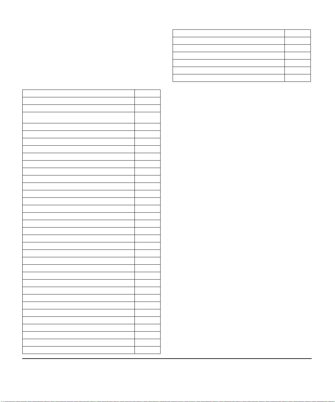
HP 5406R zl2 Switch
The HP 5406R zl2 switch ships with the 5400R zl2 Management Module and
open, 6-slot chassis (J9821A). The switch needs at least one power supply to
operate. The 5406R zl2 switch bundles are not shown.
Figure 1-1. HP 5406R zl2 Switch (J9821A)
1-5
Page 16
Introducing the HP 5400R zl2 Switches
Introducing the HP 5400R zl2
Switches
Overview of HP 5400R zl2 Switches
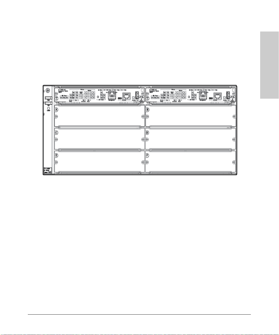
HP 5412R zl2 Switch
The HP 5412R zl2 switch ships with the 5400R zl2 Management Module and
open, 12-slot chassis (J9822A). It does not ship with any power supplies. The
switch needs at least one power supply to operate. The 5412R zl2 switch
bundles are not shown.
Figure 1-2. HP 5412R zl2 Switch (J9822A)
1-6
Page 17

Network Connectivity, Speeds and Technologies
Introducing the HP 5400R zl2
Switches
Network Connectivity, Speeds and
Technologies
These products support optional network connectivity as follows:
Table 1-1. Optional Network Connectivity, Speeds and Technologies
Transceiver Form-Factor and Connector
Introducing the HP 5400R zl2 Switches
1
Speed Technology
100-FX Fiber (multimode) LC
100 Mbps
1 Gbps
10 Gbps
100-BX Fiber (single
1000-T Copper (twisted-
1000-SX Fiber (multimode) LC
1000-LX Fiber (multimode
1000-LH Fiber (single
1000-BX Fiber (single
10-Gig CX4 Copper
10-Gig
Direct Attach
10-Gig SR Fiber (multimode) SC
10-Gig LRM Fiber (multimode) SC
Cabling
mode)
pair)
or single mode)
mode)
mode)
(twinaxial)
Copper
(twinaxial)
SFP
Connector
LC
RJ-45
LC
LC
LC
X2
Connector
CX4
SFP+
Connector
Not
Applicable
LC
LC
QSFP+
Connector
40 Gbps
10-Gig LR Fiber (single
mode)
10-Gig ER Fiber (single
mode)
40-Gig SR4 Fiber (multimode) MPO
40-Gig ESR4 Fiber (multimode) MPO
40-Gig LR4 Fiber (single
mode)
SC LC
SC LC
LC
1-7
Page 18
Introducing the HP 5400R zl2 Switches
Introducing the HP 5400R zl2
Switches
Front of the Switch
Table 1-1. Optional Network Connectivity, Speeds and Technologies
1
For supported transceivers, visit www.hp.com/networking/support.
– In the first textbox, type J4858 (for 100-Mb and Gigabit information), or J8436 (for 10-Gigabit information).
– Select any of the products that display in the dropdown list.
– Select Product support information. Then click on Manuals and find the Transceiver Support Matrix.
For technical details of cabling and technologies see "Cabling and Technology Information" in the appendices.
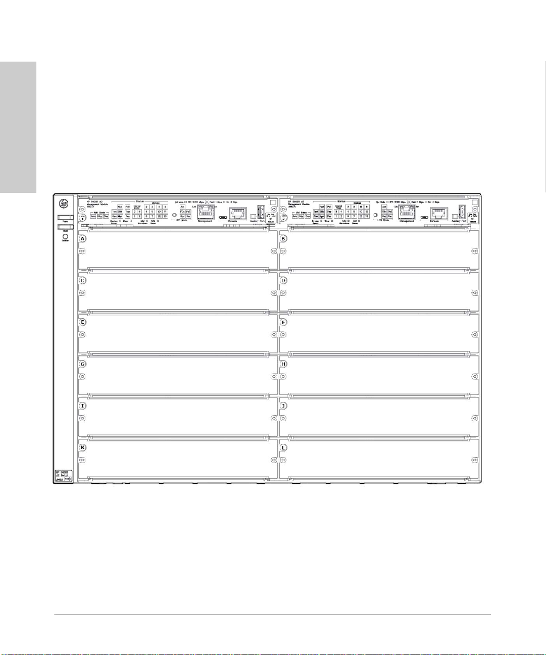
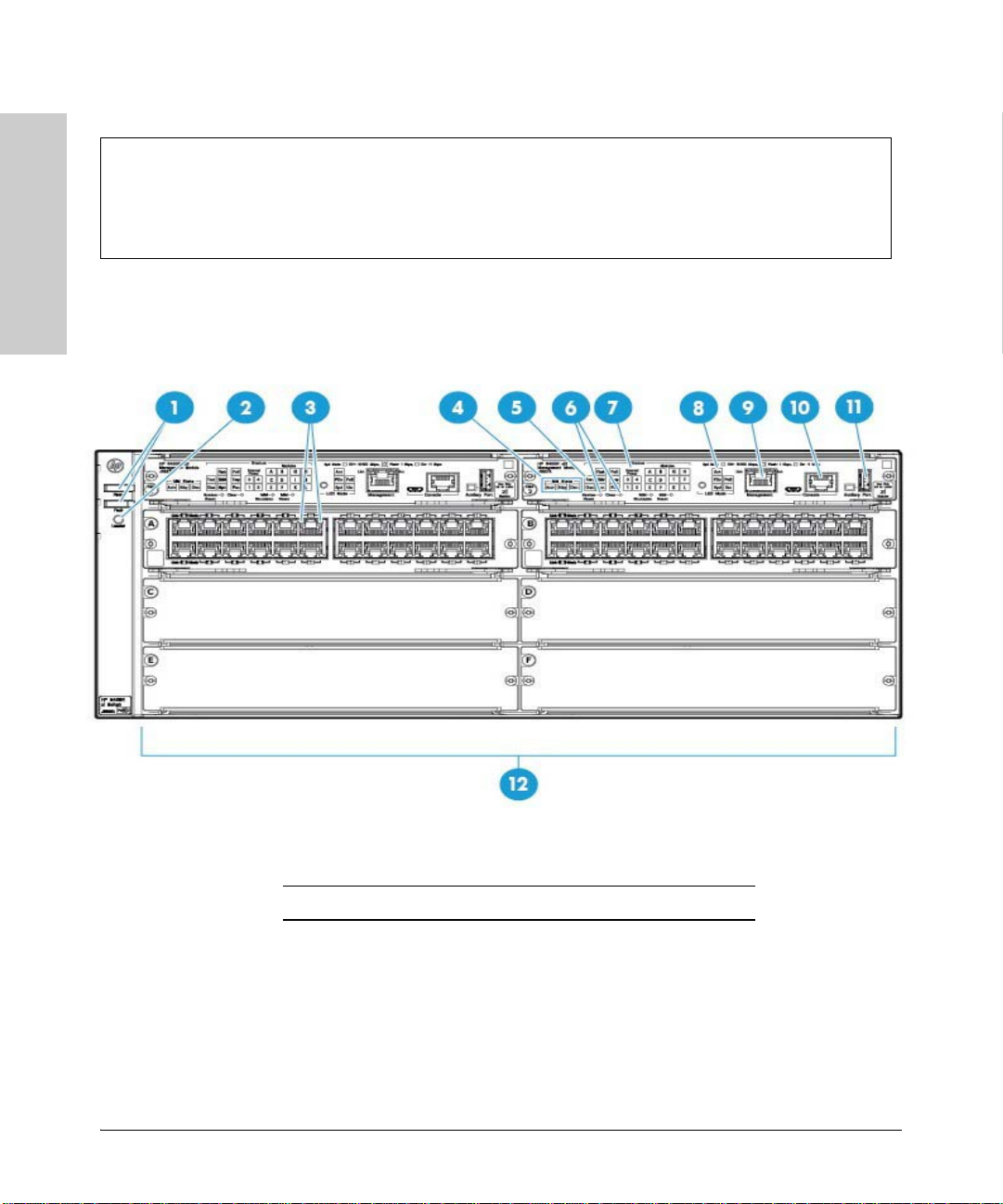
Front of the Switch
Figure 1-3. Front of 5406R zl2 Switch
Sl No Label
1 Power and Fault
LEDs
2 Locator LED
3 Module Link and Mode LEDs
4 MM Status LEDs
1-8
Page 19

Introducing the HP 5400R zl2 Switches
Introducing the HP 5400R zl2
Switches
Sl No Label
5 Status LEDs
6 Reset and Clear buttons
7 Status LEDs for the Fans, Power Supplies, and Switch
Modules
8 LED Mode Select button and indicator LEDs
9 OOBM Port
10 Console Port
11 Auxiliary Port
Front of the Switch
12 Switch Modules and slots with Link and Mode LEDs for
each port located on each module
This illustration shows the 5406R zl2 Switch, but the labeling and descriptions
apply to all of the HP 5400R zl2 switches.
For more information on HP Smart Rate port LEDs and 40G ports, see HP
Switch v3 zl2 module installation guide.
1-9
Page 20

Introducing the HP 5400R zl2 Switches
Introducing the HP 5400R zl2
Switches
Front of the Switch
LEDs
As described in the next two tables, there are LEDs on the switch chassis and
on the switch modules that keep you informed of the status of the switch and
the network connections.
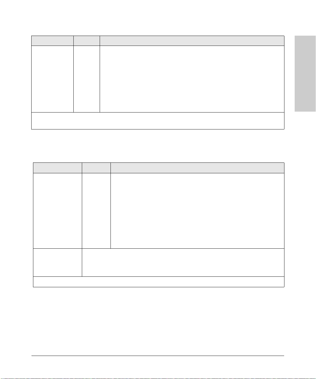
Table 1-2. Switch Chassis LEDs
LEDs State Meaning
Power
(green)
On The switch is receiving power.
Off The switch is NOT receiving power.
Fault
(orange)
Locator
(blue)
Te st
(green/Orange)
DIMM
(green/Orange)
Chas
(green)/Orange
Off The normal state; indicates that there are no fault conditions on the switch.
Blinking1A fault has occurred on the switch, one of the switch modules, an individual port, a power
supply, or a fan. The Status LED for the module or other device with the fault will flash
simultaneously.
On On briefly at the beginning of switch self test after the switch is powered on or reset. If
On
Blinking
Off
Off The normal operational state; the switch is not undergoing self test.
On
Green
Blinking
Orange
On DIMM status is known and fault free.
Off DIMM status is unknown.
Blinking
Orange
On Chassis is functioning normally.
Blinking
Orange
on for a prolonged time, the switch has encountered a fatal hardware failure, or has
failed its self test. See chapter 4, “Troubleshooting” for more information.
The Locator LED is used to locate a specific chassis in a area full of chassis. The LED
can be set to be on solid or blink for a specified number of minutes (1-1440). The default
is 30 minutes. Use the command “chassislocate”.
The switch self test and initialization are in progress after you have power cycled or
reset the switch. The switch is not operational until this LED goes off. The Self Test LED
also comes on briefly when you “hot swap” a module into the switch and the module is
automatically self tested.
A component of the switch has failed its self test. The Status LED for that component,
1
for example a switch module, and the switch Fault LED will flash simultaneously.
If DIMM, Fault, and Self Test LEDs are blinking, DIMM failed self-test.
1
If DIMM and Fault LEDs are blinking, an operational fault has occurred.
If fast blinking (400ms On and 400ms Off), an operational alert occurred and is
unresolved.
If the Chassis backplane has a fault, or the fan tray has been removed, or if there are
multiple fan failures.
Flash
(green/Orange)
On Flash Card status is known and fault free
Off
Flash Card status is unknown.
1-10
Page 21

Introducing the HP 5400R zl2
Switches
LEDs State Meaning
Blinking
Orange
If Flash, Fault, and Self Test LEDs are blinking, Secure digital card failed self-test.
1
If Flash and Fault LEDs are blinking, an operational fault has occurred.
If fast blinking (400ms On and 400ms Off), an operational alert occurred and is unresolved
(for example, the Secure digital is not present).
Mgmt
(green/Orange)
PoE
(green/Orange)
On
Off
Blinking
Orange
On
Off
A Management module is present and fault free.
The switch is powered off.
There is a fault on the Management module.
1
If any PoE modules are installed.
If no PoE modules are installed.
Introducing the HP 5400R zl2 Switches
Front of the Switch
Te mp
(green/Orange)
Fan
(green/Orange)
Internal Power
(green/Orange numbers
corresponding to
the power supply
positions)
System Reset
Button
MM Shutdown/
Reset Button
Slow
Blinking
Orange
Fast
Blinking
Orange
Internal PoE fault.
1
External load fault or denied PoE power.
2
Off Switch temperature is normal.
Blinking
Orange
An over temperature condition has been detected.
1
On The cooling fans are operating normally.
Blinking
Orange
One or more of the cooling fans have failed. The switch Fault LED will be blinking
1
simultaneously.
On A power supply is installed in the position in the back of the switch corresponding to the
number, and the supply is plugged in to an active AC power source.
Off A power supply is not installed in the position corresponding to the number.
Blinking
Orange
The power supply installed in the position corresponding to the number is not plugged
1
in to an active AC power source, or has experienced a fault. The switch Fault LED will
be blinking simultaneously.
Single
Full chassis system is reset, without failover.
press (0.2 5 seconds)
Single
press (0.2 -
Management Module shuts down. If a standby management module is present, failover
occurs. If there is no standby management module, the system reset occurs.
5 seconds)
1-11
Page 22

Introducing the HP 5400R zl2 Switches
Introducing the HP 5400R zl2
Switches
Front of the Switch
LEDs State Meaning
Modules (green letters
corresponding to
the switch module
slots)
In PoE Mode:
LED Mode Select
(5 green LEDs)
On A module is installed in the switch module slot corresponding to the letter and the module
is undergoing or has passed self test. This also occurs when you install a module when
the switch is already powered on (“hot swap”).
Off A module is not installed in the switch module slot corresponding to the letter.
1
Blinking
The module status LED flashes very briefly when a module is being hot swapped. If the
LED flashes for a prolonged time, the module in the slot corresponding to the letter has
On
Blinking
Blinking2
Off
failed self test or encountered some other fault condition. See chapter 4,
“Troubleshooting” for a more information.
PoE is ok for this slot.
1
PoE internal fault for this slot.
PoE load fault or insufficient power for this slot.
The module in this slot is not a PoE module.
Act Indicates that the port Mode LEDs are displaying network activity information.
FDx Indicates that the port Mode LEDs are lit for ports that are in Full Duplex Mode.
PoE Indicates which ports are supplying PoE power.
• If the Mode LED is on the port is providing PoE power.
• If the Mode LED is off the port is not providing PoE power.
• If the Link LED is on the port is enabled for PoE.
• If the Link LED is off the port is disabled for PoE.
• If the Link LED is blinking Orange, the port has an error or the port is denied power
due to insufficient power.
Spd Indicates the Port LEDs are displaying the connection speed at which each port is
operating:
• if the Port LED is off, the port is operating at 10 Mbps or at 100 Mbps
• if the Port LED is blinking, the port is operating at 1 Gbps
• if the Port LED is on continuously, the port is operating at 10 Gbps
Usr Reserved for future development
Auxiliary (green/
orange) For more
information see
the Management
and Configuration
Guide for your
switch.
Blinking
green
Indicates the switch is processing a USB command file.
1
On green The switch has successfully finished processing the USB command file.
Blinking
Orange
Indicates an error condition.
2
Off Indicates that no USB device has been inserted, or that the inserted USB device cannot
be recognized, or that no command file can be found on the inserted USB device.
1-12
Page 23
Introducing the HP 5400R zl2 Switches
Introducing the HP 5400R zl2
Switches
LEDs State Meaning
MM State Active Indicates that this is the Active management module when one or two management
modules are installed in the switch.
Standby Indicates that this is the Standby management module when two management modules
are installed in the switch.
Down
1
The blinking behavior is an on/off cycle once every 1.6 seconds, approximately.
2
The blinking behavior is an on/off cycle once every 0.5 seconds, approximately.
Indicates that this management Module has been shut down via the Module Shutdown
switch or via a CLI command.
Front of the Switch
Table 1-3. Switch Module LEDs
These LEDs are located on the modules themselves, one pair for each port.
LED State Meaning
Link On Indicates the port is enabled and receiving a link beat signal (for the twisted-pair
Mode Depending on the mode selected, displays the following: network activity information, whether
1
The blinking behavior is an on/off cycle once every 1.6 seconds, approximately.
ports), or a strong enough light level (for the fiber-optic ports) from the connected
device.
Off One of these conditions exists:
• no active network cable is connected to the port
• the port is not receiving link beat or sufficient light
• the port has been disabled through the switch console, the web browser
interface, Intelligent Management Center, or other network management tool.
Blinking
Orange
the port is configured for Full Duplex operation, maximum speed operation, or whether PoE
power is being supplied or not. See “LED Mode Select Button and Indicator LEDs” below for
more information.
The port has failed self test. The switch Fault, Self Test LEDs, and appropriate
1
module status LEDs will flash simultaneously.
For more information on HP Smart Rate port LEDs and 40G ports, see HP
Switch v3 zl2 module installation guide.
1-13
Page 24
Introducing the HP 5400R zl2 Switches
Introducing the HP 5400R zl2
Switches
Act
FDx
Front of the Switch
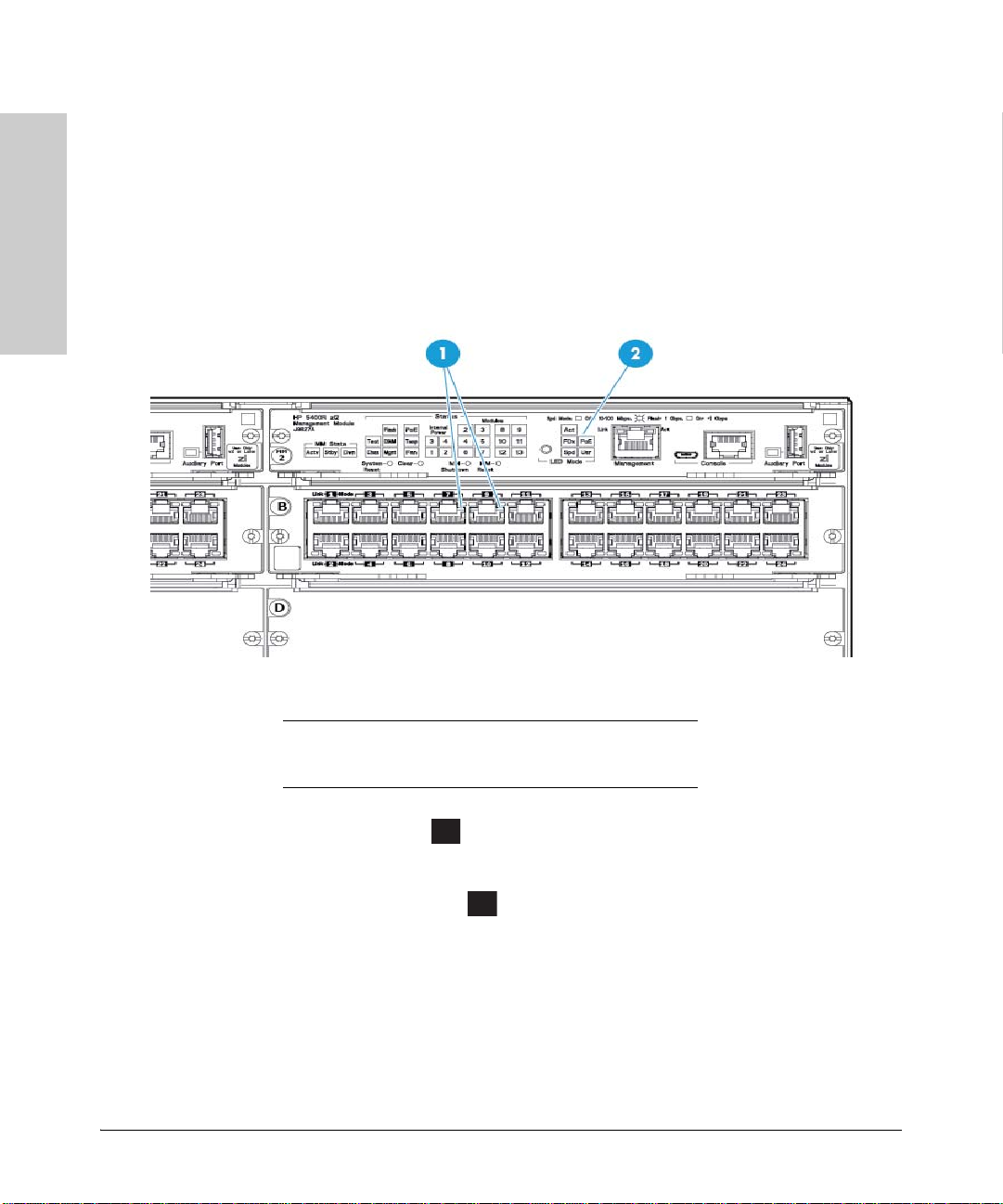
LED Mode Select Button and Indicator LEDs
To optimize the amount of information that can be displayed for each of the
switch ports, the 5400R zl2 switches use a Mode LED for each port. The
operation of this LED is controlled by the LED Mode Select button on the
switch chassis, and the current selection is indicated by the mode indicator
LEDs near the button. Press the button to change from one mode to the next.
Figure 1-4. Mode LEDs and LED Mode Select Button
1 Mode LEDs (one for each port)
2 LED Mode Select button and indicator LEDs
■ If the Activity indicator LED is lit, each port Mode LED displays
activity information for the port—it flickers faster for the higher traffic
rates.
■ If the Full Duplex indicator LED is lit, the port Mode LEDs light for
those ports that are operating in full duplex.
■ If the speed indicator LED is lit, the port LEDs behave as follows to
indicate the connection speed for the port:
• Off = 10 Mbps or 100 Mbps
• Blinking = 1 Gbps (the blinking behavior is a repeated on/off cycle
once every 0.5 sec.)
• On = Faster than 1 Gbps
1-14
Page 25

Introducing the HP 5400R zl2 Switches
Introducing the HP 5400R zl2
Switches
PoE
Front of the Switch
For 10/100/1000BASE-T, SFP and SFP+ Ports:
• Off = 10 Mbps or 100 Mbps
• Flashing = 1 Gbps
• On = >1Gbps
For HP Smart Rate ports:
•Off = Not linked
• Slow Flash = 1 Gbps
• Double Flash = 2.5 Gbps
• Triple Flash = 5 Gbps
• On = 10 Gbps
For QSFP+ ports:
•Off = Not linked
• Fast Flash = 40 Gbps
For more information on HP Smart Rate port LEDs and 40G ports in speed
mode, see HP Switch v3 zl2 module installation guide.
■ If the PoE indicator LED is lit, the Link and Mode LEDs indicate PoE
status:
Link LED:
• On = PoE is enabled on this port
• Off = PoE is disabled on this port.
• Slow Blinking Orange = Internal PoE fault on this port.
• Fast Blinking Orange = This port is denied PoE power or has an
external load fault.
Mode LED:
• On = PoE power is be supplied on this port
• Off = PoE is not being supplied on this port.
Console Port
There are two console ports on the switch. These ports are used to connect a
console to the switch. The one port uses the serial cable supplied with the
switch and the other port uses a MicroUSB cable which is not supplied with
the switch. This connection is described under “Connecting a Console to the
Switch” in chapter 2, “Installing the 5400R zl2 Switches”. The console is a fullfeatured interface that can be used to configure, monitor, and troubleshoot
the switch. It can be run on a PC, laptop, or handheld device emulating a VT100 terminal, or on a standard VT-100 terminal.
1-15
Page 26

Introducing the HP 5400R zl2 Switches
Introducing the HP 5400R zl2
Switches
Front of the Switch
Out-of-Band Management (OOBM) Port
This RJ-45 port is used to connect a dedicated management network to the
switch.
To use: connect an RJ-45 network cable to the Management port to manage
an HP 5400R zl2 Switch through Telnet from a remote PC or a UNIX worksta
tion.
To use this port, the switch must have an IP address. IP settings can be
configured through a Console port connection or automatically from a DHCP/
Bootp server.
A networked out-of-band connection through the Management port allows
you to manage data network switches from a physically and logically separate
management network.
For more information, see the "Network Out-of-Band Management (OOBM)"
appendix in the Management and Configuration Guide at: www.hp.com/
networking/support.
System Reset Button
-
This button will reset the entire switch, including the second management
module, when powered on. This action clears any temporary error conditions
that may have occurred, executes the switch self test, and resets all network
activity counters to zero. The counters are displayed in the switch console
interface, the switch web browser interface, and through SNMP network
management applications, such as Intelligent Management Center.
Press the Reset button also after changing the module type that is installed in
any of the switch module slots while the switch is powered on. See “Hot
Swapping Switch Modules” on
You can also use the no module <slot> command to erase the old module type
configuration.
page 2-27.
Clear Button
This button is used for the following purposes:
■ Deleting Passwords - When pressed for at least one second on either
one of the Management Modules, the Clear button deletes any switch
console access passwords that you may have configured. Use this feature
if you have misplaced the password and need console access.
1-16
Page 27

Introducing the HP 5400R zl2 Switches
Introducing the HP 5400R zl2
Switches
Front of the Switch
This button is provided for your convenience, but its presence means that
if you are concerned with the security of the switch configuration and
operation, you should make sure the switch is installed in a secure
location, such as a locked wiring closet.
■ Restoring Factory Default Configuration - When pressed with the
Reset button in a specific pattern, the Clear button clears any configura
tion changes you may have made through the switch console, the web
browser interface, or SNMP management, and restores the factory default
configuration to the switch. The specific patterns to accomplish the
Restore Factory Default Configuration are:
i. Press both the System Reset and Clear buttons simultaneously.
ii. Release the System Reset button, but continue to hold the Clear
button.
iii. Release the Clear button immediately when you see the Test LED
begins to flash on both the Management Modules.
For the specific method to restore the factory default configuration, see
“Restoring the Factory Default Configuration” in chapter 4, “Troubleshooting”
of this manual.
MM Shutdown Button
-
When you want to remove a module, the MM shutdown button halts all the
management functions. It will not reboot when this button is pressed.
If the system is running with two management modules and the MM shutdown
button is pressed on the active module, this causes a failover to the standby
module.
If the system is running with two management modules and the MM shutdown
button is pressed on the standby module, no failover occurs.
MM Reset Button
The MM reset button resets the Management Module to which it is attached.
If the system is running with two management modules, and if the active
module is reset, this causes a failover to the standby module.
If the system is running with two management modules and the on reset is the
active, no failover occurs.
When a user presses the reset button, the module will be reset and will reboot.
1-17
Page 28

Introducing the HP 5400R zl2 Switches
Introducing the HP 5400R zl2
Switches
Front of the Switch
If the system is running with two management modules and the MM shutdown
button is pressed on the standby module, no failover occurs.
1-18
Page 29
Introducing the HP 5400R zl2 Switches
Introducing the HP 5400R zl2
Switches
Back of the Switch
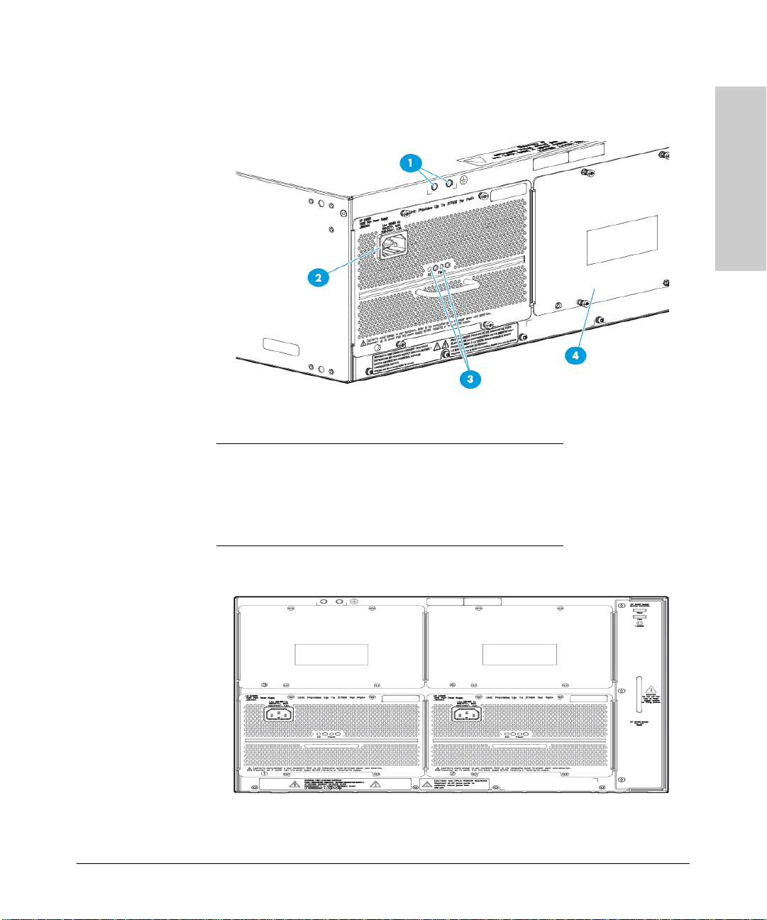
Figure 1-5. Back of a 5406R zl2 switch with one power supply
Back of the Switch
1 Ground lug mounting holes
2 AC power connector
3 Power and Fault LEDs
4 Slot for installing optional redundant power supply
Figure 1-6. Back of a 5412R zl2 switch with two power supplies
1-19
Page 30
Introducing the HP 5400R zl2 Switches
Introducing the HP 5400R zl2
Switches
CAUTION:
.
.
Disconnect AC power from the power supply BEFORE installing or
removing the supply. Otherwise, damage to the equipment may result.
.
Refer to the installation guide for proper power cord selection
Back of the Switch
Power Connector
The Series 5400R zl2 Switches do not have a power switch; they are powered
on when connected to an active AC power source.
The 5400R zl2 switches automatically adjust to any voltage between 100-127
volts or 200-240 volts when using the J9828A power supply, 110-127 volts or
200-240 volts when using the J9829A power supply, and 115-127 volts and 200240 volts when using the J9830A power supply, and either 50 or 60 Hz. There
are no voltage range settings required.
Redundant Power Supply
Load-sharing redundant power supplies J9828A, max 630W, system power
(12V), 275W of POE power; J9829A, 630W max system (12V) power, 900W max
POE power; J9830A, 630W max, system (12V) power, 2500W max POE power
can be installed in the back of the 5400R zl2 switches. To provide redundancy,
each power supply should be connected to different AC power sources. Then,
if one AC power source fails, the switch will continue to run.
Note Any combination of J9828A, J9829A and J9830A power supplies can be used
in the same switch. However, HP recommends to only use like supplies in a
unit for more deterministic behavior in event of a power supply failure.
Caution The switch redundant power supply is hot swappable, but, as indicated by the
caution statement on the power supply, it must be disconnected from AC
power before being installed or removed.
Because the switch can run on a single supply, removing a redundant supply
will not interrupt switch operation. However, with a single power supply
system will power on Interface module up to 630W. The rest of the Interface
modules are powered on the priority of the slot. The slot A has the highest
priority and the slot L has the lowest priority.
When power is restored from a second (or more) power supplies, a system
reload or interface module reset is not required to restore operation to slots
G-L. The 5400R modules will restart by themselves when power recovers.
1-20
Page 31

Introducing the HP 5400R zl2 Switches
Introducing the HP 5400R zl2
Switches
Back of the Switch
To reset the interface modules, pull each module out about half way and then
re-seat them. Do this for each module in slots G-L. For more information
regarding power see the:
■ HP Switch v2 zl Internal Power Supplies Installation Guide.
■ HP Power over Ethernet (PoE/PoE+) Devices Planning and Implemen-
tation Guide.
1-21
Page 32

Introducing the HP 5400R zl2 Switches
Introducing the HP 5400R zl2
Switches
Switch Accessories
Switch Accessories
Accessories of the 5400R zl2 switches include a 6 or 12-slot chassis for
installing any of the available v2 zl or v3 zl2 Modules. The supported v2 zl or
v3 zl2 modules include:
■ HP 5406R zl2 Switch
■ HP 5412R zl2 Switch
■ HP 5406R-44G-PoE+/2SFP+ (No PSU) v2 zl2 Switch
■ HP 5406R-44G-PoE+/4SFP (No PSU) v2 zl2 Switch
■ HP 5412R-92G-PoE+/2SFP+ (No PSU) v2 zl2 Switch
■ HP 5412R-92G-PoE+/4SFP (No PSU) v2 zl2 Switch
■ HP 5406R-8XGT/8SFP+ (No PSU) v2 zl2 Switch
■ HP 5400R zl2 Management Module
■ HP 5400R 700W PoE+ zl2 Power Supply
■ HP 5400R 1100W PoE+ zl2 Power Supply
■ HP 5400R 2750W PoE+ zl2 Power Supply
■ HP 5406R zl2 Switch Fan Tray
■ HP 5412R zl2 Switch Fan Tray
■ HP 5406R zl2 Switch
■ HP 5412R zl2 Switch
■ HP X450 4U/7U Universal 4-Post Rack Mounting Kit
■ HP 5412R 92GT PoE+ / 4SFP+ (No PSU) v3 zl2 Switch (JL001A)
■ HP 5406R 8-port 1/2.5/5/10GBASE-T PoE+ / 8-port SFP+ (No PSU) v3 zl2
Switch (JL002A)
■ HP 5406R 44GT PoE+ / 4SFP+ (No PSU) v3 zl2 Switch (JL003A)
■ HP 5406R 16-port SFP+ (No PSU) v3 zl2 Switch (JL095A)
■ 24-port Gig-T PoE+ v2 zl Module (J9534A)
■ 20-port Gig-T PoE+ / 4-port SFP v2 zl Module (J9535A)
■ 20-port Gig-T PoE+ / 2-port 10GbE SFP+ v2 zl Module (J9536A)
■ 24-port SFP v2 zl Module (J9537A)
■ 8-port 10GbE SFP+ v2 zl Module (J9538A)
■ 8-port 10GBase-T v2 zl Module (J9546A)
■ 24-Port 10/100 PoE+ v2 zl Module (9547A)
■ 20-port Gig-T / 2-port 10-GbE SFP+ v2 zl Module (J9548A)
1-22
Page 33

Introducing the HP 5400R zl2 Switches
Introducing the HP 5400R zl2
Switches
Switch Accessories
■ 20-port Gig-T / 4-port SFP v2 zl Module (J9549A)
■ 24-port Gig-T v2 zl Module (J9550A)
■ 12-port Gig-T / 12-port SFP v2 zl Module (J9637A)
■ HP MSM775 zl Premium Controller Module (J8940A)
■ HP Advanced Services v2 zl Module with HDD (J9857A)
■ HP Advanced Services v2 zl Module with SSD (J9858A)
■ HP 24p 10/100/1000BASE-T PoE+ v3 zl2 Mod (J9986A)
■ HP 24p 10/100/1000BASE-T v3 zl2 Mod (J9987A)
■ HP 24p 1GbE SFP v3 zl2 Mod (J9988A)
■ HP 12p PoE+ / 12p 1GbE SFP v3 zl2 Mod (J9989A)
■ HP 20p PoE+ / 4p SFP+ v3 zl2 Mod (J9990A)
■ HP 20p PoE+ / 4p 1/2.5/5/XGT v3 zl2 Mod (J9991A)
■ HP 20p PoE+ / 1p 40GbE QSFP+ v3 zl2 Mod (J9992A)
■ HP 8p 1G/10GbE SFP+ v3 zl2 Mod (J9993A)
■ HP 8p 1/HP 2.5/5/XGT PoE+ v3 zl2 Mod (J9995A)
Note For detailed information about the v2 zl modules, see the HP Switch v2 zl
Modules Installation Guide.
For detailed information about the v3 zl2 modules, see the HP Switch v3 zl2
Modules Installation Guide.
For detailed information about PoE and PoE+ devices, see the HP PoE/PoE+
(Power over Ethernet) Devices Planning and Implementation Guide.
To view or download this guide, visit www.hp.com/networking/support.
1-23
Page 34

Introducing the HP 5400R zl2 Switches
Introducing the HP 5400R zl2
Switches
Switch Features
Switch Features
The features of the 5400R zl2 switches include:
■ Modules can be installed in any order and in any combination and can the
“hot swapped”
■ Supported transceivers can be hot swapped
■ High performance - The 5406R zl2 Switch has a routing/switching capacity
of 496.8 Gbps, with a switch fabric speed of 561.6 Gbps and a throughput
of 396 Mbps, and the 5412R zl2 Switch has a routing/switching capacity
of 993.6 Gbps, with a switch fabric speed of 1123.2 Gbps and a throughput
of 792 Mbps
■ Plug-and-play networking - all ports are enabled—just connect the
network cables to active network devices and your switched network is
operational
■ Automatic learning of the network addresses in the switch’s 16,000-
address forwarding table, with configurable address aging value
■ Full-duplex operation available on all ports
■ Easy management of the switch through several available interfaces:
• web browser interface - an easy to use built-in graphical interface that
• console interface - a full featured, easy to use, VT-100 terminal inter-
• Intelligent Management Center - a SOA based HP Network manage-
■ Support for the Spanning Tree Protocol to eliminate network loops
■ Support for up to 2048 IEEE 802.1Q-compliant VLANs so you can divide
the attached end nodes into logical groupings that fit your business needs
■ Layer 3 routing functionality:
• Static IP routing - provides manually configured routing for both IPv4
can be accessed from common web browsers
face for out-of-band switch management, or for TELNET access to
the switch. The console includes complete switch management
through a command line interface (CLI) and a slightly reduced feature
set accessible through an intuitive menu interface
ment application that accurately discovers and displays your switch
on network maps and provides a graphical interface for configuring
and monitoring your switch
and IPv6 networks
1-24
Page 35

Introducing the HP 5400R zl2 Switches
Introducing the HP 5400R zl2
Switches
Switch Features
• Routing Information Protocol (RIP) - provides RIPv1 and RIPv2
routing
• OSPF - provides OSPFv2 for IPv4 routing and OSPFv3 for IPv6 routing
• Policy-based routing - uses a classifier to select traffic that can be
forwarded based on policy set by the network administrator.
• Border Gateway Protocol (BGP) - provides IPv4 Border Gateway
Protocol routing, which is scalable, robust, and flexible
■ Support for many other advanced features to enhance network perfor-
mance, security, and control - for a description, see the Management and
Configuration Guide which is on the HP networking Web site.
■ Support for IEEE 802.3af standard, IEEE 802.3at standard, and
pre-standard PoE devices.
■ Supports dual management module capability.
■ Supports 100% POE+ capacity at low line
■ Supports existing v2 zl and v3 zl2 modules
■ Support for three new Power Supplies
• BPSU (Base Power Supply unit - J9828A): Lower cost alternative
• LPSU (Low Power Supply unit - J9829A)
– Dual-output 12V and 54V, with one C16 power receptacle
– For support of mid-range POE/POE+ installations
• HPSU (High Power Supply Unit - J9830A)
– Dual-output 12V and 54V, with two C20 power receptacle
– For support of maximum POE/POE+ installations
■ Support for Trusted Platform Module (TPM) subsystem for storing certif-
icates and secure identity
1-25
Page 36

Introducing the HP 5400R zl2 Switches
Introducing the HP 5400R zl2
Switches
Switch Features
1-26
Page 37

Installing the HP 5400R zl2
Switches
Installing the HP 5400R zl2 Switches
The HP 5400R zl2 switches come with an accessory kit that includes the
brackets for mounting the switch in a standard 19-inch telco rack, or in an
equipment cabinet. The switches have rubber feet already attached so they
can be securely located on a horizontal surface. This chapter shows you how
to install your HP 5400R zl2 switches.
Included Parts
The 5400R zl2 switches have the following components shipped with them:
■ HP 5400R zl2 Switch Quick Setup Guide and Safety/Regulatory Informa-
tion
■ HP Switches General Safety and Regulatory Information
■ One HP 5400R zl2 Management Module (J9827A)
■ One HP 5406R zl2 Switch Fan Tray (J9831A) or HP 5412R zl2 Switch Fan
Tray (J9832A)
■ One HP 5406R zl2 Switch Rack Mounting Kit (5066-3042) or HP 5412R zl2
Switch Rack Mounting Kit (5066-3043)
■ Cable Manager Kit (5189-8716)
2
Note Power Supplies are not included with the HP 5400R zl2 Switches. They are to
be ordered separately. Each of the 5406R switches come with two power
supply slots and the 5412R switches come with four power supply slots. Three
different power supplies are available to be used with the switches: J9828A,
J9829A, and J9830A.
2-1
Page 38

Installing the HP 5400R zl2 Switches
Installing the HP 5400R zl2
Switches
Included Parts
Switch Accessories
Included Accessories with 5406R zl2
Switch
One HP 5400R zl2 Management Module
(J9827A)
One HP 5406R zl2 Switch Fan Tray
(J9831A)
Included Accessories with HP 5412R zl2
Switch
One HP 5400R zl2 Management Module
(J9827A)
One HP 5412R zl2 Switch Fan Tray
(J9832A)
Power Cords
Power cord, use one of the following according to the country of usage:
Country/Region J9830A
Australia/New Zealand
China
Mainland Europe/South Korea
India
Japan/Thailand
Denmark/Switzerland
United Kingdom/Hong Kong/Singapore/
Malaysia
United States/Canada 125V
South Africa
Taiwan/USA 250V
Israel
Argentina
Brazil
Chile
Power Supply Cable
8121-1550
8121-1551
8121-1554
8121-1074
8121-1555
8121-1287
8121-1549
8121-1553
8121-1552
8120-6362
8121-1010
8121-0925
8121-1101
8121-0923
1
2
2-2
Page 39

Installing the HP 5400R zl2 Switches
Installing the HP 5400R zl2
Switches
Included Parts
Country/Region J9829A
Australia
China
Europe/South Korea
Japan
Thailand/Philippines
Denmark
Switzerland
United Kingdom/Hong Kong/Singapore/
Malaysia
South Africa/India
Taiwan
Israel
Argentina
Brazil
Chile
North America 110V
Country/Region J9828A
Australia
China
Europe/South Korea
Japan
Thailand/Philippines
India
Denmark
Switzerland
United Kingdom/Hong Kong/Singapore/
Malaysia
South Africa
Taiwan
Israel
Argentina
Brazil
Chile
USA/Canada
Power Supply Cable
8121-1476
8121-1484
8121-1479
8120-5338
8121-1485
8121-1486
8121-1480
8121-1475
8121-1483
8121-1511
8121-1478
8121-1481
8121-1474
8121-1477
8121-0914
Power Supply Cable
8121-0834
8120-8707
8120-6811
8120-4753
8121-0668
8121-0780
8120-6814
8120-6815
8120-6809
8120-6813
8121-0974
8121-1035
8120-6869
8121-1069
8120-6980
8121-0914
1
Japan: NEMA 6-20P, 200V.
2
Taiwan/U.S.A. 250V: NEMA L6-20P, 250V
Japan Power
Cord Warning
2-3
Page 40

Installing the HP 5400R zl2 Switches
Installing the HP 5400R zl2
Switches
Installation Procedures
Installation Procedures
Summary
Follow these easy steps to install your switch. The rest of this chapter provides
details on these steps.
1. Prepare the installation site (page 2-8). Make sure the physical
environment into which you will be installing the switch is properly
prepared including having the correct network cabling ready to connect
to the switch, and having a good location for the switch. See
some installation precautions.
2. Install switch modules (page 2-8). The 5400R zl2 switches have six or
12 universal slots for installing any of the HP Switch v2 zl or v3 zl2
modules. Some of the 5406R zl2 and 5412R zl2 switches come with
preinstalled modules. Depending on where you will install your 5400R zl2
switch, it may be easier to install the modules first. The modules are “hot
swappable” though, so they can also be installed and removed after the
switch is powered on.
page 2-7 for
Note Make sure you use only HP Switch v2 zl or v3 zl2 Modules in your 5400R
zl2 switches. HP switch vl zl modules are not supported.
3. Install power supplies (page 2-12). The 5406R zl2 and 5412R zl2
switches supports up to two power supplies. It may be easier to install the
power supplies after mounting the switch. The switch must have at least
one power supply to operate.
4. Verify the switch passes self test (page 2-14). This is a simple process
of plugging the switch into a power source and observing that the LEDs
on the switch’s front panel and on the modules show correct operation.
It may be easier to verify if the switch passes self test before mounting
the switch.
5. Mount the switch (page 2-16). The 5400R zl2 switches can be mounted
in a 19-inch telco rack, in an equipment cabinet, or on a horizontal surface.
An optional HP X450 4U/7U Universal 4-Post Rack Mounting Kit (J9852A)
is available for mounting 5400R zl2 switches in a cabinet. However, if you
want to ship in a cabinet or rack, its recommended to use the 4-post kit
in a HP rack. See the installation details for more information.
6. Install the Grounding Wire (page 2-20). If a grounding wire is to be
attached to the switch chassis, the grounding lug must be removed and a
wire crimped to it and the grounding lug must be reinstalled.
2-4
Page 41

Installing the HP 5400R zl2 Switches
Installing the HP 5400R zl2
Switches
Installation Procedures
7. Connect the switch to a power source (page 2-21). Once the switch
is mounted, plug it in to the nearby main power source.
8. Connect the network devices (page 2-22). Using the appropriate
network cables, connect other switches, hubs, routers, computers,
servers, printers, and other network devices to the switch ports. For more
information, see “Connect the Network Devices” on
page 2-22.
Note The 10/100/1000-T ports on the v2 zl or v3 zl2 Modules comply with IEEE
802.3x standard which includes the Auto MDI/MDI-X feature. This
feature allows you to use straight-through twisted-pair cable for all of
your twisted-pair network connections.
9. Connect a console to the switch (optional—page 2-23). You m ay wi sh
to modify the switch’s configuration, for example, to configure an IP
address so it can be managed using a web browser or from an SNMP
network management station. Configuration changes can be made easily
through the switch’s console interface.
At this point, the switch is fully installed. See the rest of this chapter if you
need more detailed information on any of these installation steps.
2-5
Page 42

Installing the HP 5400R zl2 Switches
Installing the HP 5400R zl2
Switches
Installation Procedures
Installation Precautions
Follow these precautions when installing your 5400R zl2 switch:
WARNING
■ Devices installed in a rack or cabinet should be mounted as low
as possible, with the heaviest device at the bottom and progres
sively lighter devices installed above.
The rack or cabinet should be adequately secured to prevent it
from becoming unstable and/or falling over.
■ Ensure a cover plate is installed on any empty switch power
supply or module slot. A cover plate is required for safe
operation, and to ensure proper switch cooling. Never have
more than one power supply or module slot uncovered at a
time while the switch is powered on.
■ To avoid energy and mechanical hazards, never allow any part
of your body, jewelry, tool, or other foreign object to enter any
module or power supply slots.
■ This unit may have more than one power supply cable. To fully
power down the switch, you must disconnect all power supply
cables from the unit.
-
2-6
Page 43

Installing the HP 5400R zl2 Switches
Installing the HP 5400R zl2
Switches
Installation Precautions (continued)
Installation Procedures
Cautions
■ If the switch is to be shipped in a rack, HP Shock Rack and an HP X4504U/
7U Universal 4-Post Rack Mount Kit (J9852A) for each switch.
■ Ensure the power source circuits are properly grounded, then use the
power cord supplied with the switch to connect it to the power source.
■ If your installation requires a different power cord than the one supplied
with the switch and power supply, be sure the cord is adequately sized
for the switch’s current requirements. In addition, be sure to use a power
cord displaying the mark of the safety agency that defines the regulations
for power cords in your country. The mark is your assurance that the
power cord can be used safely with the switch and power supply.
■ When installing the switch, note that the AC outlet should be near the
switch and should be easily accessible in case the switch must be
powered off.
■ Ensure the switch does not overload the power circuits, wiring, and over-
current protection. Each power supply should be connected to a dedi
cated branch circuit to prevent tripping building circuit breakers. To
determine the possibility of overloading the supply circuits, add together
the ampere ratings of all devices installed on the same circuit as the
switch and compare the total with the rating limit for the circuit. The
maximum ampere ratings are usually printed on the devices near the AC
power connectors.
■ Do not install the switch in an environment where the operating ambient
temperature might exceed 45°C (113°F).
■ Allow three to four inches of space around the sides and back of the
switch to make sure the air flow for the switch is not restricted.
2-7
Page 44

Installing the HP 5400R zl2 Switches
Installing the HP 5400R zl2
Switches
Installation Procedures
1. Prepare the Installation Site
Cabling Infrastructure
Ensure the cabling infrastructure meets the necessary network specifications.
See Appendix B, “Cabling and Technology Information” on
information.
Installation Location
Before installing the switch, plan its location and orientation relative to other
devices and equipment:
■ In the front of the switch, allow at least 7.6 cm (3 inches) of space for the
twisted-pair and fiber-optic cabling.
■ In the back of the switch, allow at least 10.2 cm (4 inches) of space for the
power cord and cooling.
■ On the sides of the switch, leave at least 7.6 cm (3 inches) for cooling.
2. Install Switch Modules
page B-1 for more
Install switch modules into the slots as shown in the illustration below. For
installation details, see the instructions in the manual that comes with the
module.
Caution Make sure you install only HP Switch v2 zl or v3 zl2 Modules. HP Swtich vl zl
modules are not supported.
Avoid any electrostatic discharge problems by handling the modules only by
their bulkheads.
The slot cover can be removed, and the module can be installed with either a
flat-bladed or Torx T-10 screwdriver. Retain the slot cover for future use.
Module
Installation
■ Any of the supported Switch v2 zl or v3 zl2 Modules can be installed in
any of the slots.
Notes
2-8
Page 45

Installing the HP 5400R zl2 Switches
Installing the HP 5400R zl2
Switches
■ The modules can be “hot swapped”, installed after the switch is already
Installation Procedures
powered on, and normally will be immediately operational. See “Hot
Swapping the Switch Module” on
■ Ensure you fully insert the modules. That is, press the module into
page 2-27.
the slot using the extractor handles, until the bulkhead on the module is
contacting the front face of the switch chassis.
■ Once the module is fully inserted, screw in the two retaining screws to
secure the module in place. The screws should be tightened until they are
secure, but not overtightened.
■ If you do not use one or more of the slots, ensure the slot cover plate is
still attached over the slot for safe operation and proper switch cooling.
For safety, you should not have more than one module slot uncovered at
a time.
■ Although these procedures show the 6-slot chassis, the procedures are
the same for the 12-slot chassis.
Figure 2-1. Module being installed in a chassis
1 Retaining Screw
2 Open Ejector handle
3 Management Module
2-9
Page 46

Installing the HP 5400R zl2 Switches
Installing the HP 5400R zl2
Switches
Installation Procedures
Installing a Management Module Battery
The battery on the management module is used to keep time for the internal
switch clock. The internal clock will not function properly without a battery.
WARNING ■ The battery requires special handling at end-of-life. The battery
can explode or cause burns if disassembled, charged, or exposed
to water, fire or high temperature. After replacing the battery,
properly dispose of used battery according to instructions.
■ There is a risk of explosion if the battery is replaced by an
incorrect type. Ensure to replace the battery with the same type.
■ To avoid shorting of battery, remove and properly dispose of
battery before returning a Management Module for repair.
Installing a New Battery.
ATTENTION ll y a danger d'explosion s'il y a remplacement incorrect de la batterie.
2-10
Figure 2-1. Battery location on Management Module
1. Insert the new battery with the lettering and the plus “+” sign facing up.
2. Install the management module into the switch.
Remplacer uniquement avec une batterie du même type ou d'un type
équivalent recommandé par le constructeur.
Page 47

Installing the HP 5400R zl2 Switches
Installing the HP 5400R zl2
Switches
Installation Procedures
Mettre au rebut les batteries usagées conformément aux instructions du
fabricant.
Perchlorate Notice. If this product contains a real-time clock battery or
coin cell battery it may contain perchlorate and may require special handling
when recycled or disposed of in California and other certain states.
Perchlorate material - special handling may apply see:
www.dtsc.ca.gov/hazardouswaste/perchlorate Web site for more information.
2-11
Page 48

Installing the HP 5400R zl2 Switches
Installing the HP 5400R zl2
Switches
Installation Procedures
3. (Optional) Install Another Power Supply
Caution The 5400R zl2 switches are designed to provide continuously operating PoE
or PoE+ power in the event of a single power supply failure with only a loss
of PoE or PoE+ power to lower priority ports.
If more than one power supply fails while the switch is at or near maximum
operating power (that is: the sum total of all PoE supply capacity minus the
largest supply, see chapter 2 and 4 of the PoE (Power over Ethernet) Devices
Planning and Implementation Guide) loss of all PoE power may result.
To return PoE power to the ports, without causing the switch to reboot, when
there are two or more power supplies still supplying 12V power, unplug the
power cord for 5 seconds and re-plug it for each power supply one at a time.
The following are the addition power supplies that can be installed in the back
of the 5400R switches. The 5406R zl2 switch can hold up to two power supplies
and the 5412R zl2 switch can hold up to four power supplies.
■ J9828A: 630W of max power of system 12V power or 275w of max PoE
power. Total Max power is 700w.
■ J9829A: 630W of max power of system 12V power or 900W of max PoE
power. Total Max power is 1100W.
■ J9830A (with 2 power cords): 630W of max power of system 12V power
or 2500W of max PoE power. Total Max power is 2750W.
■ J9830A (with MAIN power cord only): 630W of max power of system 12V
power or 1100W of max PoE power. Total Max power is 1400W.
Note Any combination of J9828A, J9829A and J9830A power supplies can be used
2-12
To prevent overloading of the building circuits breakers, the second power
supply must be connected to a different AC power source from the other
supply. This also helps with redundancy, if one AC power source fails, the
switch will continue to run.
Install the second power supply into power slot number 2 as shown in Figure
2-3. Although these procedures show the 6-slot chassis, the procedures are
the same for the 12-slot chassis. The slot cover can be removed with either a
flat-bladed or Torx T-10 screwdriver. Retain the slot cover for future use.
in the same switch. However, HP recommends to only use like supplies in a
unit for more deterministic behavior in event of a power supply failure.
Page 49

Installing the HP 5400R zl2 Switches
Installing the HP 5400R zl2
Switches
CAUTION:
.
.
Disconnect AC power from the power supply BEFORE installing or
removing the supply. Otherwise, damage to the equipment may result.
.
Refer to the installation guide for proper power cord selection
Insert the power supply into
the opening, then slide it all
the way in until it connects
to the switch. The power
supply face plate will be
flush with the back face of
the switch.
Installation Procedures
Caution The switch power supplies are hot swappable; they can be installed while the
switch is receiving power from the supply in the other slot. But, as indicated
by the caution statement on the power supply, the supply must not be
connected to AC power before being installed or removed.
For safety and proper switch cooling, if either of the power supply slots are
not being used, make sure to attach the cover plate over the slot. Please see
the “Installation Precautions” on
page 2-7 for more information.
For installation details, see the instructions in the manual that comes with the
power supply.
2-13
Page 50

Installing the HP 5400R zl2 Switches
Installing the HP 5400R zl2
Switches
Connect power
cord to power
connector
Installation Procedures
Figure 2-2. Installing a power supply
Once the power supply is installed, tighten the four retaining screws that hold
it in place. The screws can be tightened with either a flat-bladed or Torx T-10
screwdriver. Be careful not to overtighten the screws.
4. Verify the Switch Passes Self Test
After you have installed any modules and the optional second power supply,
but before mounting the switch in its network location, you should first verify
it is working properly by plugging it into a power source and verifying it passes
its self test.
If you have installed a second power supply, repeat these procedures with the
second power supply to verify it works correctly also.
1. Connect the power cord supplied with the switch to the power connector
on the back of the switch, and then into a properly grounded electrical
outlet.
1 Handle to insert the power supply into the Chassis.
2 Screws
2-14
Page 51

Installing the HP 5400R zl2 Switches
Installing the HP 5400R zl2
Switches
Installation Procedures
Figure 2-3. Power connector on back of switch
Note The 5400R zl2 switches do not have a power switch. They are powered on
when the power cord is connected to the switch and to a power source.
If your installation requires a different power cord than the one supplied with
the switch, see the “Installation Precautions” on
2. Check the LEDs on the switch and on each of the switch modules. The
LED behavior is described on the next page.
If the LED display is different than what is described, especially if the
Fault LED stays on for more than approximately 120 seconds or it starts
blinking, the self test has not completed correctly. See chapter 4,
“Troubleshooting” for diagnostic help.
page 2-7.
Figure 2-4. Switch Fault, Module, and Chassis LEDs
1 Switch Fault LED
2 Switch Module LEDs: Link and Mode LEDs for each port
3 Switch Chassis LEDs
When the switch is powered on, it performs its diagnostic self test. The entire
download, initialization, and self test process can take up to 2 minutes for a
fully loaded chassis, depending on the number and type of modules installed
in the switch.
2-15
Page 52

Installing the HP 5400R zl2 Switches
Installing the HP 5400R zl2
Switches
Installation Procedures
LED Behavior:
During the self test:
■ Initially, Power, Fault, Locator, and all the switch chassis LEDs are on. Then,
after approximately 30 seconds, all the module LEDs go on as the modules
receive power and code is downloaded to them, the Fault LED goes off,
and the chassis LEDs turn orange and then go off except Te st , Fan, and
Power, which turn green.
■ When the download of code to the modules is completed, the module
LEDs go off. You may see each port LED go on briefly, in sequence, as the
port is tested.
■ For the duration of the self test, the Te st LED stays on.
When the test completes successfully:
■ The Power LED stays on, and the Status LEDs on the switch chassis stay
on for the devices installed: one for each switch module installed, one for
each power supply installed, and one for all the fans.
■ The Fault, Locator, and Test LEDs are off.
■ The port LEDs on the switch modules go into their normal operational
mode:
• If the ports are connected to active network devices, the Link LEDs
• If the ports are not connected to active network devices, the LEDs
stay on and the Mode LEDs behave according to the mode selected.
In the default mode (Activity), the Mode LEDs should flicker showing
network activity on the port.
will stay off.
2-16
For more information on 40G port LED information, see v3 zl2 module
installation guide.
5. Mount the Switch
After the modules and optional power supply are installed and you have
verified the switch passes self test, you are ready to mount the switch in a
stable location. The 5400R zl2 switches can be mounted in these ways:
■ in a rack or cabinet
■ on a horizontal surface
Page 53

Installing the HP 5400R zl2 Switches
Installing the HP 5400R zl2
Switches
1 0.625 inch (1.588
cm)
2 0.50 inch (1.27
cm)
Installation Procedures
Rack or Cabinet Mounting
The 5400R zl2 switches are designed to be mounted in any EIA-standard 19inch telco rack or in an equipment cabinet such as a server cabinet. If you are
installing the switch in an equipment cabinet, read the following “Equipment
Cabinet Note” on
page 2-17.
Equipment
Cabinet
Note
If you are installing the switch in an equipment cabinet, in place of the
12-24 screws supplied with the switch, use the clips and screws that came with
the cabinet. Plan which four holes that you will be using in the cabinet and
install all four clips and partially install the two bottom screws, as described
in step 2 on the previous page, before proceeding to step 3. The number of
holes depends on the switch and the rack kit being used. To reduce the switch
weight and ease while installation, you can remove the power supplies during
the racking process.
WARNING For safe operation, please read the “Installation Precautions” on page
2-6 and page 2-7 before mounting the switch.
1. Determine position of switch in rack and install a cage nut in the lower
hole of the lowest rack unit.
2-17
Page 54

Installing the HP 5400R zl2 Switches
Installing the HP 5400R zl2
Switches
1 Rack Brackets
2 Flat Head
Screws
Installation Procedures
2. Install a screw half-way into this cage nut.
3. Align the included Rack Mount Bracket such that the half-hole lines up
with the screw, install additional cage
bracket.
nuts at each hole position in the
2-18
Page 55

Installing the HP 5400R zl2 Switches
Installing the HP 5400R zl2
Switches
1 Pan Head Screw
2 Cable Manager
3 Pan Head Screw
Installation Procedures
4. Repeat for opposite column in the rack.
5. Secure the Rack Mount Brackets to the switch with included flat head
screws.
2-19
Page 56

Installing the HP 5400R zl2 Switches
Installing the HP 5400R zl2
Switches
1 Install the retainer
horizontally
2 Rotate the retainer
to the vertical
position
Installation Procedures
Note Use only the included 6 mm/0.24 inch flat head screws. Using any of the 8 mm/
0.31 inch screw included in other rack mounting kits interferes with internal
components.
6. Rest the switch on the two half-way installed screws and secure the
switch to the rack using the top hole in each Rack Mount Bracket.
Note Ensure the air flow is not restricted around the sides and back of the switch.
2-20
7. Align each Cable Manager such that two holes in the Cable Manager align
with two empty holes in the Rack
screws.
8. Snap the Cable Retainers into the arms of the Cable Managers.
Mount Bracket and secure with two
Horizontal Surface Mounting
Place the switch on a table or other horizontal surface. Use a sturdy surface
in an uncluttered area. You may want to secure the networking cables and
switch power cord to the table legs or other part of the surface structure to
help prevent people from tripping over the cords.
6. Install the Grounding Wire
If a grounding wire is to be attached to the switch chassis, the grounding lug
must be removed and a wire crimped to it and the grounding lug must be
reinstalled.
1. Use a Torx T25 driver and remove the grounding lug and two screws from
the back of the switch.
Page 57

Installing the HP 5400R zl2 Switches
Installing the HP 5400R zl2
Switches
2. Crimp the grounding lug to a properly grounded grounding wire.
3. Re-attach the grounding lug to the switch with the two screws.
Figure 2-5. Attaching grounding lug to the 5400R zl2 switch
Installation Procedures
1 Grounding Lug
2 Grounding Lug Screws
7. Connect the Switch to a Power Source
1. Plug the included power cord into the switch’s power connector and into
a nearby properly grounded AC power source.
If a redundant power source is available, it is desirable to power one
switch power supply from the regular AC source, and the other power
supply from the independent AC source. This will provide redundancy in
AC power to the switch, as long as the switch PoE power usage falls within
the capability of one power supply. If both power supplies are plugged
into a common AC source, there is still power supply redundancy, that is,
protection against power supply failure, but if the AC source fails, the
switch will lose all power.
2. Re-check the LEDs during self test. See “LED Behavior” on page 2-16.
2-21
Page 58

Installing the HP 5400R zl2 Switches
Installing the HP 5400R zl2
Switches
Installation Procedures
8. Connect the Network Cables
The type of network connections you will need to use depends on the types
of switch modules you have installed in your 5400R zl2 Switch. See the
documentation accompanying the modules for cabling configurations and
procedures for those modules.
In general for all the modules, when a network cable from an active network
device is connected to the switch, the Link LED for the switch port should go
on. If the Link LED does not go on, use the table below to help solve the
problem, and see the module documentation for troubleshooting procedures.
For more information on 40G port LED information, see v3 zl2 module
installation guide.
Condition Diagnostic Tip
Port LED is
still off when
a cable is
connected
Try the following procedures:
• For the indicated port, verify both ends of the cabling, at the switch and the connected device, are
securely connected.
• Verify the connected device and switch are both powered on and operating correctly.
• Verify you have used the correct cable type for the connection:
– for all twisted-pair connections, the RJ-45 connectors on the 5400R zl2 switches allow you to
use either straight-through cable or crossover cable when the port is in the “Auto”
configuration.
– for fiber-optic connections, verify the transmit port on the switch is connected to
the receive port on the connected device, and the switch receive port is connected to
the transmit port on the connected device.
See appendix B, “Switch Ports and Network Cables” for information on cables.
• Verify the port has not been disabled through a switch configuration change.
• Verify the connection parameters in the configurations of the switch port and the connected
device match. Mismatched configurations are a frequent cause of connection problems.
You can use the console interface, or, if you have configured an IP address on the switch, use the
web browser interface, or Intelligent Management Center network management software to
determine the state and configuration of the port and re-enable the port if necessary.
• If the other procedures don’t resolve the problem, try using a different port or a different cable.
2-22
Page 59

Installing the HP 5400R zl2 Switches
Installing the HP 5400R zl2
Switches
Installation Procedures
10. (Optional) Connect to the Management Console of the Switch
The 5400R zl2 switches have a full-featured, easy to use console interface for
performing the following tasks:
■ Monitor switch and port status and observe network activity counters
■ Modify the switch’s configuration
■ Read the event log and access diagnostic tools to help in troubleshooting
■ Download new software to the switch
■ Add passwords and other security features to control access to the switch
from the console, web browser interface, and network management
stations
The console can be accessed through these methods:
■ Out-of-band: Connect a PC or VT-100 terminal, to be used as a console,
directly to the switch using the serial cable that comes with the 5400R zl2
switches. If the PC or terminal has a 25-pin serial connector, you can use
a readily available 9-pin to 25-pin serial cable, or attach a 9-to-25 pin
straight-through adapter to the PC end of the cable.
■ In-Band: Access the console using telnet from a PC or UNIX station on
the network, and a VT-100 terminal emulator. This method requires that
you first configure the switch with an IP address and subnet mask by using
either out-of-band console access or through DHCP/Bootp.
Terminal Configuration
To connect a console to the switch, configure the PC terminal emulator as a
VT-100 or DEC VT-100 (ANSI) terminal, or use a VT-100 terminal and configure
it to operate with these settings:
■ any baud rate from 2400 to 115200 (the switch automatically senses the
speed)
■ 8 data bits, 1 stop bit, no parity, and flow control set to None
■ for Windows Terminal program, also disable (uncheck) the “Use Function,
Arrow, and
■ for the Hilgrave HyperTerminal program, select the “Terminal keys”
option for the “Function, Arrow, and
If you want to operate the console using a different configuration, ensure you
change the settings on both the terminal and on the switch. Change the switch
settings first, then change the terminal settings, and reestablish the console
session.
Ctrl Keys for Windows” option
Ctrl keys act as” parameter
2-23
Page 60

Installing the HP 5400R zl2 Switches
Installing the HP 5400R zl2
Switches
Installation Procedures
Setting Up a Console Connection
To access the Switch through an Console port (out-of-band) connection,
follow these steps:
1. Configure the management console as described above under
"Configuring the Management Console Connection".
2. For a direct console connection, connect the PC or terminal to the
Console serial port using one of these console cables:
a. A DB9-to-RJ45 cable (shipped with the switch).
b. A micro-USB cable (not provided).
The USB console drivers are available at www.hp.com/networking/support.
The following are the steps to download the driver:
c. Type a product model (for example, 5400) or product number in the
d. Select one of the switches from the dropdown list, and click the
e. From the options that appear, select Software downloads (on the
Auto Search text box.
Display selected button.
right-hand side). Then, download the "USB Console Port Drivers and
Information".
2-24
Also, both console ports are not active at the same time and after sometime
the USB console port times out.
Page 61

Installing the HP 5400R zl2
Switches
Figure 2-6. Console Connection
Installing the HP 5400R zl2 Switches
Installation Procedures
1 Console Port
2 RJ-45 to DB9 console cable
3 Optional USB console cable (not
4 To PC running a terminal emulator
supplied with the switch
supplied)
program, or a VT-100 terminal
3. Power on the management console (terminal or PC). If you are using a
PC, start the PC terminal program.
4. For a direct console connection through the Console port:
a. Press Enter two or three times to display the copyright page, and the
message "Press any key to continue".
b. Press any key to display the switch console command (CLI) prompt;
for example: HP 5900#
c. Continue the console session to configure the switch by following the
procedure in "Minimal Configuration Through the Out-of-Band
Console Connection" on page 3-2
2-25
Page 62

Installing the HP 5400R zl2 Switches
Installing the HP 5400R zl2
Switches
5
4321
9
876
12345678
12345678
Installation Procedures
Console Cable Pinouts
The console cable has an RJ-45 plug on one end and a DB-9 female connector
on the other end. Table 2-2 describes the mapping of the RJ-45 to DB-9 pins
module.
Figure 2-7. RJ-45 to DB-9 pinouts
Table 2-2. Mapping of RJ-45 to DB-9
2-26
RJ-45 (Signal reference from
Chassis)
Reserved 1 8 CTS
Reserved 2 6 DSR
TXD 3 2 RXD
Reserved 4 1 DCD
GND 5 5 GND
RXD 6 3 TXD
Reserved 7 4 DTR
Reserved 8 7 RTS
DB-9 (Signal reference from PC)
9 RI
Telnet Console Access
To access the switch through a telnet session, follow these steps:
1. Ensure the switch is configured with an IP address and that the switch is
reachable from the telnet workstation (for example by using a Ping
command to the switch’s IP address)
Page 63

Installing the HP 5400R zl2 Switches
Installing the HP 5400R zl2
Switches
Hot Swapping Switch Modules
2. Start the telnet program and connect to the switch’s IP address.
3. The copyright page and the message “Press any key to continue” will
display. Press a key, and the switch console CLI prompt will display.
If you want to continue with console management of the switch at this time
through either a direct connection or a TELNET session, see chapter 3,
“Getting Started With Switch Configuration” for some basic configuration
steps. For more detailed information, refer to the Management and Config
uration Guide which is on the HP networking Web site.
Out-of-Band Management (OOBM) Port
This RJ-45 port is used to connect a dedicated management network to the
switch.
To use: connect an RJ-45 network cable to the Management port to manage
an HP 5400R zl2 Switch through Telnet from a remote PC or a UNIX worksta
tion.
To use this port, the switch must have an IP address. IP settings can be
configured through a Console port connection or automatically from a DHCP/
Bootp server.
-
-
A networked out-of-band connection through the Management port allows
you to manage data network switches from a physically and logically separate
management network.
For more information, see the "Network Out-of-Band Management (OOBM)"
appendix in the Management and Configuration Guide at: www.hp.com/
networking/support.
Hot Swapping Switch Modules
The switch modules can be “hot swapped” (except for the Management
Module, it is not hot swappable), that is installed or replaced while the switch
is powered on (See Module Installation Notes on
differ slightly, though between adding new modules to an empty slot or
replacing modules with the same type, and exchanging the module with a
different type.
page 2-8). The procedures
2-27
Page 64

Installing the HP 5400R zl2 Switches
Installing the HP 5400R zl2
Switches
Hot Swapping Switch Modules
Adding or Replacing Modules
If a module has to be replaced with one of the same type, or you are expanding
the switch capability by adding a module in a slot where one was not previ
ously installed (since the last switch reboot), the replaced or new module is
immediately operational; there is no interruption to the switch operation.
When you are replacing a module in a slot with another module of different
type, the new module does not immediately operate, since the switch contains
configuration (such as VLAN membership) involving ports of the older
module. Replacing the module does NOT automatically remove such config
uration. To remove the older configuration, run the following command from
the command line interface:
no module X
where, X is the slot letter of the module to be replaced. After you run
command, the slot is restored to a state where no module was previously
installed. When you insert the new module, the module operates immediately.
-
-
2-28
Page 65

Getting Started With Switch
Configuration
Getting Started With Switch Configuration
This chapter is a guide for using the console Switch Setup screen to quickly
assign an IP (Internet Protocol) address and subnet mask to the switch, set a
Manager password, and, optionally, configure other basic features.
For more information on using the switch console and the other switch
management interfaces: the web browser interface and the SNMP manage
ment tool, Intelligent Management Center, see the Management and Config-
uration Guide on the HP networking Website.
Recommended Minimal Configuration
In the factory default configuration, the switch has no IP (Internet Protocol)
address and subnet mask, and no passwords. In this state, it can be managed
only through a direct console connection. To manage the switch through inband (networked) access, you should configure the switch with an IP address
and subnet mask compatible with your network. Also, you should configure
a Manager password to control access privileges from the console and web
browser interface. Other parameters in the Switch Setup screen can be left at
their default settings, or you can configure them with values you enter.
3
-
Many other features can be configured through the switch’s console interface,
to optimize the switch’s performance, to enhance your control of the network
traffic, and to improve network security. Once an IP address has been config
ured on the switch, these features can be accessed more conveniently through
a remote Telnet session, through the switch’s web browser interface, and from
an SNMP network management station running a network management
program, such as Intelligent Management Center. For a listing of switch
features available with and without an IP address, refer to “How IP Addressing
Affects Switch Operation” in the Management and Configuration Guide
which is on the HP networking Website.
For more information on IP addressing, see “IP Configuration” in the Manage-
ment and Configuration Guide.
-
3-1
Page 66

Getting Started With Switch Configuration
Getting Started With Switch
Configuration
Note By default, the switch is configured to acquire an IP address configuration
from a DHCP or Bootp server. To use DHCP/Bootp instead of the manual
method described in this chapter, see “DHCP/Bootp Operation” in the
Management and Configuration Guide which is on the HP networking
Website.
Using the Switch Setup Screen
The quickest and easiest way to minimally configure the switch for management and password protection in your network is to use a direct console
connection to the switch, start a console session, and access the Switch Setup
screen.
1. Using the method described in the preceding section, connect a terminal
device to the switch and display the switch console command (CLI)
prompt (the default display).
The CLI prompt appears displaying the switch model number, for
example:
HP 5412Rzl2#
2. At the prompt, enter the setup command to display the Switch Setup
screen. The following illustration is an example of a Setup screen with
default settings.
Figure 3-1. Switch Setup Screen
3-2
Page 67

Getting Started With Switch Configuration
Getting Started With Switch
Configuration
3. Use the Tab key to select the Manager Password field and enter a manager
password of up to 16 characters.
4. Tab to the IP Config (DHCP/Bootp) field and use the Space bar to select the
Manual option.
5. Tab to the IP Address field and enter the IP address that is compatible with
your network.
6. Tab to the Subnet Mask field and enter the subnet mask used for your
network.
7. Press Enter, then S (for Save).
The following is information on the fields in the Setup screen. For more
information on these fields, see the Management and Configuration Guide
which is on the HP networking Web site.
Parameter Default
System Name blank Optional; up to 25 characters, including spaces
System Contact blank Optional; up to 48 characters, including spaces
Manager Password blank Recommended; up to 16 characters (no blank spaces)
Logon Default CLI The default setting selects the command line interface for console access.
The alternative is the Menu interface.
Time Zone 0 (none) Optional; 1440 to -1440. The number of minutes your location is to the
West (-) or East (+) of GMT.
Community Name public Default setting recommended.
Spanning Tree Enabled No Default setting recommended unless STP is already running on your network
Default Gateway blank Recommended; Enter the IP address of the next-hop gateway node if network
Time Sync Method TimeP Optional; The protocol the switch uses to acquire a time signal. The options
TimeP Mode Disabled Synchronizes the time kept on the switch to the TimeP server.
IP Config DHCP/Bootp Set to Manual unless a DHCP/Bootp server is used on your network to
IP Address xxx.xxx.xxx.xxx Recommended; If you set IP Config to Manual, then enter an IP address
Note: The IP address and subnet mask assigned for the switch must be compatible with the IP addressing used in
your network. For more information on IP addressing, see the Management and Configuration Guide which is on the
HP networking Web site.
Subnet Mask xxx.xxx.xxx.xxx Recommended; If you entered an IP address, then enter a subnet mask
or the switch will be used in complex network topologies.
traffic needs to be able to reach off-subnet destinations.
are SNTP and TimeP.
configure IP addressing.
compatible with your network.
compatible with your network.
3-3
Page 68

Getting Started With Switch Configuration
Getting Started With Switch
Configuration
Where to Go From Here
The above procedure configures your switch with a Manager password, IP
address, and subnet mask. As a result, with the proper network connections,
you can now manage the switch from a PC equipped with Telnet, a web
browser interface, or from an SNMP-based network management station
using a tool such as IMC.
Some basic information on managing your switch is included in the next
section. For more information on the console, web browser, and SNMP
management interfaces and all the features that can be configured on the
5400R zl2 switches, see the Management and Configuration Guide which is
on the HP networking Web site.
To Recover from a Lost Manager Password: If you cannot start a console session at the manager level because of a lost Manager password, you
can clear all passwords and user names by getting physical access to the
switch and pressing and holding the Clear button for a full second.
3-4
Page 69

Using the IP Address for Remote Switch Management
Getting Started With Switch
Configuration
Getting Started With Switch Configuration
Using the IP Address for Remote Switch
Management
With your 5400R zl2 switches, you can use the switch’s IP address to manage
the switch from any PC that is on the same subnet as the switch. You can use
either a Telnet session or a standard web browser to manage the switch.
Starting a Telnet Session
To access the switch through a Telnet session, follow these steps:
1. Ensure the switch is configured with an IP address and that the switch is
reachable from the PC that is running the Telnet session (for example, by
using a ping command to the switch’s IP address).
2. Start the Telnet program on a PC that is on the same subnet as the switch
and connect to the switch’s IP address.
3. You will see the copyright page and the message “Press any key to
continue”. Press a key, and you will then see the switch console command
(CLI) prompt, for example (assuming there is no password):
HP 5400Rzl2#
Enter help or ? to see a list of commands that can be executed at the
prompt. Entering any command followed by help provides more detailed
context help information about the command. Entering any command
followed by ? displays a list of options that are available at that point in
the command entry.
Starting a Web Browser Session
Your 5400R zl2 switch can be managed through a graphical interface that you
can access from any PC or workstation on the network by running your web
browser and typing in the switch’s IP address as the URL. No additional
software installation is required to make this interface available; it is included
in the switch’s onboard software.
An example web browser interface screen is shown in the next illustration.
3-5
Page 70

Getting Started With Switch Configuration
Getting Started With Switch
Configuration
Using the IP Address for Remote Switch Management
Figure 3-2. Switch Web Browser Interface - Status Overview
For more information on using the web browser interface, please see the
Management and Configuration Guide which is on the HP networking Web
site.
An extensive help system is also available for the web browser interface. To
access the help system though, the subnet on which the switch is installed
must have access to the internet, or Intelligent Management Center needs to
be installed on a network management station that is on the subnet.
3-6
Page 71

Replacing Components
4
Replacing Components
This chapter shows you how to remove and install the following components:
■ Power supplies (see page 4-2)
■ Fan trays (see page 4-4)
■ Management module (see page 4-5)
■ Management module components SD card (see page 4-6)
For a complete list of parts and part numbers, see (page 2-1)
Hot Swapping The HP 5400R zl2 Switch supports “hot swapping” - the ability to replace the
following hardware components while the switch is operating: a fan tray,
power supply (if a second power supply is installed), and interface module.
The Management module and its components are not hot swappable.
The hot swapping feature allows you to remove or install modules without
powering off or rebooting the switch. Swapped-in modules are recognized by
the switch and begin functioning immediately, after they are installed.
Caution The HP 5400R zl2 Switch and its components are sensitive to static discharge.
Use an antistatic wrist strap and observe all static precautions when hot
swapping components. For example, connect your antistatic wrist strap to the
ground point on the front of the switch, above the rightmost power supply bay.
WARNING This unit may have more than one power supply cable. To fully power
down the switch, you must disconnect all power supply cables from the
unit.
4-1
Page 72

Replacing Components
Replacing Components
Replacing Power Supplies
Replacing Power Supplies
If your HP 5400R zl2 Switch is configured with redundant power supplies, you
will not suffer any loss of traffic or performance if a power supply fails.
Replace the failed component as soon as possible. One of the Internal Power
LEDs on the management module will blink simultaneously with the switch
Fault LED indicating which power supply failed.
Although these procedures show the 6-slot chassis, the procedures are the
same for the 12-slot chassis.
To remove an AC power supply:
1. Ensure the AC power supply is not plugged into an AC power source on
the failed power supply.
2. Using either a flat-bladed or Torx T-10 screwdriver loosen the retaining
screws and remove the failed power supply.
Figure 4-1. Power supply removal
4-2
Page 73

Replacing Components
Replacing Components
Replacing Power Supplies
3. Insert the power supply into the opening. Slide it all the way in until it
connects to the switch. The power supply face plate will be flush with the
back face of the switch.
Figure 4-2. Power supply installation
4. Tighten the four retaining screws that hold it in place. Be careful not to
overtighten the screws.
For more details, see the HP Switch zl2 Internal Power Supply Installation
Guide.
4-3
Page 74

Replacing Components
Replacing Components
Retaining Screws
Handle
Retaining Screws
Handle
Replacing Fan Trays
Replacing Fan Trays
When a fan fails the Fan Status LED on the management module blinks
simultaneously with the switch Fault LED. In this case, the entire fan tray
needs to be replaced. You cannot replace individual fans.
The fan tray is hot swappable. It can be removed and replaced without
removing power from the switch. However, install the new fan tray
immediately (after two minutes) after removing the old fan tray to avoid
overheating and switch shutdown (after three minutes). The fan tray is
provided with a hotswap controller on the backplane to control the fan power
interface during insertion and removal.
Although these procedures show the 6-slot chassis, the procedures are the
same for the 12-slot chassis.
WARNING To avoid contact with spinning fans, if you are hot swapping out the
fan tray assembly, pull the assembly out one-inch and allow the fans
to stop rotating (approximately 20 seconds) before pulling it all the
way out.
Figure 4-3. 5406R zl2 Switch Fan Tray removal Figure 4-4. 5406R zl2 Switch Fan Tray insertion
4-4
To replace a fan tray:
1. Using either a flat-bladed or Torx T-10 screwdriver loosen the retaining
screws holding the fan tray assembly and pull the fan tray assembly out.
2. Install the new fan tray assembly and tighten the retaining screws.
Page 75

Replacing the Management Module
Replacing Components
Replacing Components
Replacing the Management Module
The switch does not have to be powered off to remove the management
module, however, when the management module is removed all ports will lose
communication. HP networking recommends replacing all components
during the scheduled down time.
To install (or replace) a Management Module:
1. On the module, unscrew the retaining screws enough to disconnect them
from the threaded holes in the switch.
2. Using the extractor handles, pull the module out from the slot.
3. Remove the flash disk from the failed module and install it into the
replacement module.
4. Remove the battery from the failed module and dispose of properly.
5. Install the new battery that came with the replacement module. See
“Installing a Management Module Battery” on page 2-10 for instructions.
6. Install the replacement module into the switch.
7. Use an equal amount of pressure and push both extractor handles closed
to completely seat the module.
8. Tighten the retaining screws.
Figure 4-5. Management Module removal and installation
1 Management Module
4-5
Page 76

Replacing Components
Replacing Components
Replacing the Management Module SD Card
2 Extractor handles
3 Retaining screws
You can use MM Shutdown button to replace an active Management Module.
This helps the standby MM to become active.
Replacing the Management Module SD
Card
The SD card is the primary non-volatile storage medium located on the
management module that contains both the boot software and configuration
files. When a SD card fails, the SD status LED on the management module
blinks simultaneously with the switch Fault LED. Both the SD and the Fault
flashing are amber in color (LEDs are green with normal functionality). In
addition, the Locator LED will be a solid blue.
Installing an SD Card
To install (or replace) an SD card:
1. Using either a flat-bladed or Torx T-10 screwdriver loosen the retaining
screws securing the management module. (You cannot access the SD
when the management module is installed. This prevents inadvertent
removal of the system image while the system is running.)
2. Using the extractor handles, pull the management module out from the
slot If a retention pin in front of the SD card slot is present, then you must
use needle-nose pliers to pull the pin out of the hole before the SD card
can be removed.
4-6
Page 77

Replacing the Management Module SD Card
Replacing Components
Replacing Components
Figure 4-6. Secure Digital installation and removal
3. Slide out the old SD card.
4. Slide in the new SD card being careful not to bend any pins.
5. Reinstall the management module into the switch.
6. Use an equal amount of pressure and push both extractor handles closed
to completely seat the module.
7. Tighten the retaining screws.
4-7
Page 78

Replacing Components
Replacing Components
Replacing the Management Module SD Card
4-8
Page 79

Troubleshooting
Troubleshooting
This chapter describes how to troubleshoot your 5400R zl2 switches. Note that
this document describes troubleshoot ing mostly from a hardware perspective.
You can perform more in-depth troubleshooting using the software tools
available with the switch, including the full-featured console interface, the
built-in web browser interface, and IMC, the SNMP-based network manage
ment tool. For more information, see the chapter “Troubleshooting” in the
Management and Configuration Guide, which is on the HP networking Web
site at
www.hp.com/networking/support.
This chapter describes the following:
■ Basic troubleshooting tips (page 5-2)
■ Diagnosing with the LEDs (page 5-4)
■ HP networking tools (page 5-10)
■ Hardware diagnostic tests (page 5-11)
■ Restoring the factory default configuration (page 5-14)
■ Downloading new code (page 5-15)
■ HP Customer Support Services (page 5-15)
5
-
5-1
Page 80

Troubleshooting
Troubleshooting
Basic Troubleshooting Tips
Basic Troubleshooting Tips
Most problems are caused by the following situations. Check for these items
first when starting your troubleshooting:
■ Faulty or loose cables. Look for loose or obviously faulty connections.
If they appear to be OK, make sure the connections are snug. If that does
not correct the problem, try a different cable.
■ Non-standard cables. Non-standard and miswired cables may cause
network collisions and other network problems, and can seriously impair
network performance. Use a new correctly-wired cable or compare your
cable to the cable in appendix B, “Cabling and Technology Information”
on
page B-1 for pinouts and correct cable wiring. A category 5 cable tester
is a recommended tool for every 100Base-TX and 1000Base-T network
installation.
■ Improper Network Topologies. It is important to make sure you have
a valid network topology. Common topology faults include excessive
cable length and excessive repeater delays between end nodes. If you have
network problems after recent changes to the network, change back to
the previous topology. If you no longer experience the problems, the new
topology is probably at fault.
In addition, you should make sure that your network topology contains
no data path loops. Between any two end nodes, there should be only
one active cabling path at any time. Data path loops will cause broadcast
storms that will severely impact your network performance.
With your 5400R zl2 switches, if you wish to build redundant paths
between important nodes in your network to provide some fault toler
ance, you should enable Spanning Tree Protocol support on the switch.
This ensures that only one of the redundant paths is active at any time,
thus avoiding data path loops. Spanning Tree can be enabled through the
switch console, the web browser interface, or IMC.
The 5400R zl2 switches also support Trunking, which allows multiple
network cables to be used for a single network connection without
causing a data path loop. See the Management and Configuration Guide
for more information on Spanning Tree and on Trunking, which is on the
HP networking Web site.
5-2
Page 81

Basic Troubleshooting Tips
Troubleshooting
Troubleshooting
■ Connecting to devices that have a fixed full-duplex configuration.
The RJ-45 ports on the 5400R zl2 switches are all configured as “Auto”.
That is, when connecting to attached devices, the switch will operate in
one of two ways to determine the link speed and the communication mode
(half duplex or full duplex):
• if the connected device is also configured to Auto, the switch will
automatically negotiate both link speed and communication mode
• if the connected device has a fixed configuration, for example 100
Mbps, at half or full duplex, the switch will automatically sense the
link speed, but will default to a communication of half duplex
Because the 5400R zl2 switches behave in this way (in compliance with
the IEEE 802.3 standard), if a device connected to the switch has a fixed
configuration at full duplex, the device will not connect correctly to the
switch. The result will be high error rates and very inefficient communi
cations between the switch and the device.
Ensure that all devices connected to the 5400R zl2 switches are configured
to auto negotiate, or are configured to connect at half duplex (all hubs are
configured this way, for example).
If necessary though, you can modify the configuration of the ports on the
5400R zl2 switches to match the configuration of the connected device.
Use the switch console, the web browser interface, or IMC to modify the
port configuration.
-
■ Check the port configuration. A port on your 5400r zl2 switch may not
be operating as you expect because it has been put into a “blocking” state
by Spanning Tree, GVRP (automatic VLANs), or LACP (automatic
trunking). (Note that the normal operation of the Spanning Tree, GVRP,
and LACP features may put the port in a blocking state.) Or, the port just
may have been configured as disabled through software.
Use the switch console to determine the port’s configuration and verify
that there is not an improper or undesired configuration of any of the
switch features that may be affecting the port. See the Management and
Configuration Guide which is on the HP networking Web site.
For more information on possible network problems and their solutions, refer
to the technical note “Troubleshooting LAN Performance and Intermittent
Connectivity Problems”, which can be found on the HP networking Web site
in the Reference Library,
www.hp.com/networking/support, in the A-Z index
section.
5-3
Page 82

Troubleshooting
Troubleshooting
Diagnosing with the LEDs
Power
Off with
power cord
plugged in
On Prolonged OnProlonged
On Blinking
On Blinking
On Blinking
On Blinking
On Blinking
On Blinking
On Off Off Off
On Off Off On
1
This LED is not important for the diagnosis.
2
The blinking behavior is an on/off cycle once every 1.6 seconds, approximately.
3
The fast blinking behavior is an on/off cycle once every 0.8 seconds, approximately
Diagnosing with the LEDs
Table 5-1 shows LED patterns on the switch and the switch modules that
indicate problem conditions.
1. Check in the table for the LED pattern you see on your switch
2. Refer to the corresponding diagnostic tip on the next few pages.
Table 5-1. LED Error Indicators
LED Pattern Indicating Problems
Diagnostic
Tip s
Fault
1 1 1 1 1 1
2
2
2
2
2
2
Te st
(one LED per
Module Status
1 1 1 1
On
2
Blinking
Blinking2Blinking
Blinking2Blinking
Blinking2Blinking
Off
Off
Off
1
1 1
module)
2
2
2
Power
(one LED per
power supply)
1 1 1
1 1
1 1
1 1
†
Blinking
1 1
1 1
Fan
*
Blinking
Never On
On briefly,
then Off
Blinking
†
Fast blinking
Off with cable
connected
Port Link
2
1
1
➊
➋
➌
➍
➎
➏
➐
➑
3
➒
➓
11
5-4
Page 83

Troubleshooting
Tip
Number
Diagnosing with the LEDs
Troubleshooting
Diagnostic Tips:
Problem Solution
➊
➋
➌
The power supplies
installed in the
switch are not
plugged into active
AC power sources,
or the power supply
may have failed.
A switch hardware
failure has
occurred. All the
LEDs will stay on
indefinitely.
The switch has
experienced a
backplane failure
during self test.
1. Verify the power cord is plugged into an active power source and to the switch.
Ensure these connections are snug.
2. Try power cycling the switch by unplugging and plugging the power cord back in.
3. If the Power LED is still not on, verify the AC power source works by plugging
another device into the outlet. Or try plugging the switch into a different outlet or
try a different power cord.
If the power source and power cord are OK and this condition persists, the switch
power supply may have failed. Call your authorized reseller or authorized service
provider, or use the electronic support services from HP to get assistance. See the
Customer Support/Warranty card for more information.
Try power cycling the switch. If the fault indication reoccurs, the switch may have
failed. Call your authorized reseller or authorized service provider, or use the
electronic support services from HP to get assistance. See the Customer Support/
Warranty card for more information.
The failure may be just in the communications with a single module slot, or it might
be more significant. Start a console session with the switch, and at the CLI prompt
issue the command show logging. In the event log that is displayed, there will be
messages that describe the extent of the problem. If the problem is with individual
slots, the remainder of the switch slots will be fully operational and can be used until
you get a chance to replace the switch.
If necessary to resolve the problem, contact Call your authorized reseller or
authorized service provider, or use the electronic support services from HP to get
assistance. See the Customer Support/Warranty card for more information.
➍
The module
installed in the slot
that corresponds to
the letter that is
blinking is an
invalid module.
Ensure you have installed a zl or zl2 module in the slot. The HP xl/gl/vl modules will
not fit in the interface module slots in 5400R zl2 family, and they are not compatible
with HP 5400R zl2 switch. Check to ensure the module has a Blue “zl module” or “zl2
module” symbol on it.
Remove the module from the switch and replace it with a zl module or zl2 module,
or recover the slot with the cover plate. You can remove and replace the module
without having to power down the switch. Call your authorized reseller or authorized
service provider, or use the electronic support services from HP to get information
on supported Switch zl or zl2 modules. You can also view the switch message log
for more details on specific errors. The modules that are available as of the printing
of this manual are listed on
page 1-22.
5-5
Page 84

Troubleshooting
Troubleshooting
Diagnosing with the LEDs
Tip
Number
Problem Solution
➎
The module
installed in the slot
that corresponds to
the letter that is
blinking has
experienced a self
test or initialization
fault.
The modules are all tested whenever the switch is powered on, or reset (through
the Reset button on the switch, or the Boot or Reset options in the console or web
browser interface), and when they are hot swapped (installed when the switch is
powered on).
Since the Link and Mode LEDs on the module were lit at least briefly, that indicates
that the module did receive power from the switch, but the subsequent download
process failed. Either the module is faulty, or it is a new module type that is not yet
supported by the operating code on the switch.
As HP networking introduces new modules for your HP 5400R zl2, you may have to
update the switch with new operating code that supports the new module. The
documentation that came with the module will indicate which version of the
operating code is needed to support the module. The modules that are supported in
your 5400R zl2, as of the printing of this manual, are listed on
Features”. The latest code can be downloaded from the HP networking Web site at
www.hp.com/networking/support.
First verify the switch has a version of code that supports the module that is
indicating the fault. If the module is not one of the ones listed on
the module documentation to see what version of switch code is needed. Download
the new code and retest the module.
If you have the correct code installed in the switch, try removing and reinstalling the
module. You can do this without having to power down the switch. When the module
is reinstalled, it will be retested automatically.
If the fault indication reoccurs, the module may have failed. Remove the module from
the switch and replace it with another module, or recover the slot with the cover
plate. Call your authorized reseller or authorized service provider, or use the
electronic support services from HP to get assistance. See the Customer Support/
Warranty card for more information.
page 1-22 under “Switch
page 1-22, check
5-6
Page 85

Troubleshooting
Tip
Number
Diagnosing with the LEDs
Troubleshooting
Problem Solution
➏
➐
The network port
for which the Link
LED is blinking has
experienced a self
test or initialization
failure.
A fault condition
has been detected
on the power
supply installed in
the slot
corresponding to
the blinking
number.
During the module self test, described in tip number 4 earlier in this table, each
network port is also tested. If the port self test fails, the individual port is not usable,
but the rest of the ports on the module, which have passed their self test, will
continue to operate normally.
If the port is a transceiver, verify it is one of the transceivers supported by the
Module. Unsupported transceivers will be identified with this fault condition. The
supported transceivers are listed in the module Installation Guide. The transceivers
are also tested when they are “hot-swapped”--installed or changed after the
Module is installed and receiving power from the switch.
To verify the port has failed, try removing and reinstalling the module, as described
in tip number 4. For the transceivers, you can just remove and reinstall the
transceiver without having to remove the module. If the port fault indication
reoccurs, and you need to be able to use the port, you will have to replace the
transceiver or the module. In the mean time, all the other module ports will operate
normally.
For more information on 40G port self-test or initialization failure, see v3 zl2 module
installation guide.
Try removing and reinstalling the power supply.
Caution: Ensure the AC power cord is disconnected from the supply before removing
and reinstalling the supply.
Reconnect the power supply to the AC power source. If the error indication reoccurs
after the supply is reinstalled, the power supply may be faulty. Call your authorized
reseller or authorized service provider, or use the electronic support services from
HP networking to get assistance. See the Customer Support/Warranty card for more
information.
➑
One or more of the
switch cooling fans
may have failed.
Try disconnecting power from the switch and wait a few moments. Then reconnect
the power to the switch and check the LEDs again. If the error indication reoccurs,
one or more of the fans has failed. The switch has multiple fans and may continue
to operate OK under this condition if the ambient temperature does not exceed
normal room temperature, but for best operation, replace the fan tray. Call your
authorized reseller or authorized service provider, or use the electronic support
services from HP networking to get assistance. See the Customer Support/Warranty
card for more information.
5-7
Page 86

Troubleshooting
Troubleshooting
Diagnosing with the LEDs
Tip
Number
Problem Solution
➒
The network port
for which the Link
LED is blinking has
been disabled
because port
security has been
configured on the
switch and a
security violation
has been detected
on the port.
For the Port Security feature, you can configure the switch so that whenever a
security violation is detected on a port, the switch will disable the port. When a port
is disabled by this feature, the port Link LED will be continuously flashed at the fast
rate of 0.8 seconds per cycle. The blinking continues until you clear the security
violation through the switch console. In the console, you can view the identity of the
connected device that committed the security violation.
Once the security violation is cleared, you must re-enable the port through the
console.
For more information on the Port Security feature, see the Management and
Configuration Guide which is on the HP networking Web site. See
details.
For more information on 40G port self-test or initialization failure, see v3 zl2 module
installation guide.
page 5-1 for
5-8
Page 87

Troubleshooting
Tip
Number
Diagnosing with the LEDs
Troubleshooting
Problem Solution
➓
The network
connection is not
working properly.
Try the following procedures:
• For the indicated port, verify both ends of the cabling, at the switch and the
connected device, are securely connected.
• Verify the connected device and switch are both powered on and operating
correctly.
• Verify you have used the correct cable type for the connection.
– for any of the twisted-pair connections, in the default configuration (Auto),
either a straight-through or a crossover cable can be used and the switch will
automatically adjust its operation. See the “HP Auto-MDIX Feature”
description on
Note: If the module configuration is changed to one of the fixed
configuration options though (for example, 100-Full Duplex), then the port
operates as MDI-X only and the correct type of cable must be used. in
general, for connecting to an end node (MDI port), use straight-through
cable; for connecting to MDI-X ports on hubs, other switches, and routers,
use crossover cable.
– for fiber-optic connections, verify that the transmit port on the switch is
connected to the receive port on the connected device, and the switch
receive port is connected to the transmit port on the connected device, and
that both devices are transmitting correctly.
• For a 1000 Mbps connection, verify the network cabling complies with the IEEE
802.3ab standard. The cable should be installed according to the ANSI/TIA/EIA568-A-5 specifications. Cable testing should comply with the stated limitations
for Attenuation, Near-End Crosstalk, Far-End Crosstalk, Equal-Level Far-End
Crosstalk (ELFEXT), Multiple Disturber ELFEXT, and Return Loss.
The cable verification must include all patch cables from any end devices,
including the switch, to any patch panels in the cabling path.
• Verify the port has not been disabled through a switch configuration change.
You can use the console interface, or, if you have configured an IP address on
the switch, use the web browser interface, or IMC network management
software to determine the state of the port and re-enable the port if necessary.
• Verify the switch port configuration matches the configuration of the attached
device. For example, if the switch port is configured as “Auto”, the port on the
attached device also MUST be configured as “Auto”. Depending on the port type,
twisted-pair or fiber-optic, if the configurations don’t match, the results could be
a very unreliable connection, or no link at all.
If the other procedures don’t resolve the problem, try using a different port or a
different cable.
page B-8 for more information.
5-9
Page 88

Troubleshooting
Troubleshooting
HP networking tools
HP networking tools
The 5400R zl2 switches have built-in management capabilities that
proactively help you manage your network including:
■ finding and helping you fix the most common network error conditions
(for example, faulty network cabling, and non-standard network
topologies)
■ informing you of the problem with clear, easy-to-understand messages
■ recommending network configuration changes to enhance the
performance of your network
The following interfaces provide tests, indicators, and an event log that can
be used to monitor the switch and its network connections, and to help you
take advantage of these proactive networking features:
■ Intelligent Management Center - an SNMP-based network management
tool included with your switch
■ A graphical web browser interface you can use to manage your switch
from a PC that is running a supported web browser, for example Microsoft
Internet Explorer.
■ A full-featured easy-to-use console interface you can access by merely
connecting a standard terminal or PC running a terminal emulator to the
switch’s console port. The cable to make that connection is provided with
your switch. The console interface is also accessible through a telnet
connection.
See the “Troubleshooting” chapter in the Management and Configuration
Guide for more information on using these software tools to diagnose and
manage your switch, which is on the HP networking Website. See
page 5-1 for
details.
5-10
Page 89

Hardware Diagnostic Tests
Troubleshooting
Troubleshooting
Hardware Diagnostic Tests
Reasons for Resetting the Switch
Generally, you only need to reset the switch when it needs to recognize a
change in its hardware or software (console) configuration. Some
circumstances in which you will need to reset the switch are:
■ Changing certain switch configuration parameters through the console
interface. (In this case, the console provides indications when the switch
must be reset for the configuration change to be activated.)
You do not need to reset the switch when:
■ Installing a module in a previously unused slot.
■ Replacing a module with the same type of module.
■ Replacing the module with a different type of module.
Methods of Resetting the Switch
You can reset the switch by any of these methods:
■ pressing the System Reset button. On the 5400R zl2 switches, this is the
Reset button on the Management Module.
■ power cycling the switch (if both power supplies are being used, you will
have to disconnect all the power cords)
■ issuing the boot command from the switch console CLI, or selecting the
Reset or Boot option from the switch console menu, web browser inter
-
face, or Intelligent Management Center.
Testing the Switch by Resetting It
If you believe the switch is not operating correctly, you can reset the switch
to test its circuitry and operating code. To reset a switch, either:
■ Unplug and plug in the power cord (power cycling)
■ Press the System Reset button on the front of the switch
■ Select the reset or reboot option from the console, web browser interface,
or Intelligent Management Center.
5-11
Page 90

Troubleshooting
Troubleshooting
Hardware Diagnostic Tests
Power cycling the switch, pressing the System Reset button, and the software
reset or reboot options all cause the switch to perform its power-on self-test,
which almost always will resolve any temporary operational problems. These
reset processes also cause any network traffic counters to be reset to zero and
cause the System Up Time timer to reset to zero. Neither of these reset
procedures causes any changes to the switch configuration.
Checking the Switch LEDs
The self-test passes if the Fault and Test LEDs on the front of the switch go
off after approximately 90 to 150 seconds depending on the number and type
of modules installed in the switch. If these LEDs stay on longer than 180
seconds or begin blinking, the switch, or a module, or an individual transceiver
may have to be replaced as indicated by the LEDs.
See “Diagnosing With the LEDs” on page 5-4 for information on interpreting
the LED patterns.
Checking Console Messages
Useful diagnostic messages may be displayed on the console screen when the
switch is reset. As described in chapter 2 under step 8, “Connect a Console to
the Switch”, connect a PC running a VT-100 terminal emulator program or a
standard VT-100 terminal to the switch’s Console Port and configure it to run
at 9600 baud and with the other terminal communication settings shown on
page 2-23. Then, when you reset the switch, note the messages that are
displayed.
5-12
Page 91

Hardware Diagnostic Tests
Troubleshooting
Troubleshooting
Testing Twisted-Pair Cabling
If you think the cable should work but still isn’t working, it may not be
compatible with the IEEE 802.3 Type 10Base-T, 100Base-TX, or 1000Base-T
standards, as appropriate for the switch port type that the cable is connected
to. The twisted-pair cables attached to the 5400R zl2 switches must be compat
ible with these standards.To verify your cable is compatible with these standards, use a qualified cable test device.
HP networking also offers a wire testing service. Contact your HP authorized
reseller or authorized service provider or your local HP networking sales
office for more information.
Testing Switch-to-Device Network Communications
You can perform the following communication tests to verify the network is
operating correctly between the switch and any connected device that can
respond correctly to the communication test.
■ Link Test -- a physical layer test that sends IEEE 802.2 test packets to any
device identified by its MAC address
■ Ping Test -- a network layer test used on IP networks that sends test
packets to any device identified by its IP address
-
These tests can be performed through the switch console interface from a
terminal connected to the switch or through a telnet connection, or from the
switch’s web browser interface. See the Management and Configuration
Guide which is on the HP networking Web site. See
These tests can also be performed from an SNMP network management
station running a program that can manage the switch, for example, IMC.
page 5-1 for details.
Testing End-to-End Network Communications
Both the switch and the cabling can be tested by running an end-to-end
communications test -- a test that sends known data from one network device
to another through the switch. For example, if you have two PCs on the
network that have LAN adapters between which you can run a link-level test
or Ping test through the switch, you can use this test to verify the entire
communication path between the two PCs is functioning correctly. See your
LAN adapter documentation for more information on running the a link test
or Ping test.
5-13
Page 92

Troubleshooting
Troubleshooting
Restoring the Factory Default Configuration
Restoring the Factory Default
Configuration
As part of your troubleshooting process, it may become necessary to return
the switch configuration to the factory default settings. This process momen
tarily interrupts the switch operation, clears any passwords, clears the console
event log, resets the network counters to zero, performs a complete self test,
and reboots the switch into its factory default configuration including deleting
an IP address, if one is configured.
Note This process removes all switch configuration changes that you have made
from the factory default settings. This includes, for example, configuration of
VLANs, spanning tree, trunks, stacking, meshing, routing, and security.
Returning the configuration of these features to their factory default settings
(usually disabling them) may result in network connectivity issues.
If the switch has a valid configuration, and you are restoring the factory default
settings for a reason other than configuration problems, you should save the
switch configuration prior to performing the factory default reset. Then, after
the reset and resolution of the original problem, you can restore the saved
configuration to the switch. For both the save and restore processes, you can
use the console copy command. See the switch Management and Configura
tion Guide which is on the HP networking Web site. See page 5-1 for details.
-
-
You can restore the factory default configuration either on the switch itself or
through the switch console.
To execute the factory default reset on the switch, perform these steps:
1. Using pointed objects, simultaneously press both the Reset and Clear
buttons on the front of the switch.
2. Continue to press the Clear button while releasing the Reset button.
3. As soon as the Test LED begins to flash, release the Clear button.
The switch will then complete its self test and begin operating with its
configuration restored to the factory default settings.
To restore the factory default configuration using the console, execute the
erase startup-config command from the console command prompt.
5-14
Page 93

Downloading New Software
Troubleshooting
Troubleshooting
Downloading New Software
When product enhancements occur for the 5400R zl2 switches, new software
can be downloaded to the switch through several methods, for product
enhancements and new features. Please see the Management and Configu
ration Guide which is on the HP networking Web site. See page 5-1 for details.
The new software would be available on the HP networking Web site,
www.hp.com/networking/support.
HP Customer Support Services
If you are still having trouble with your switch, Hewlett-Packard offers support
24 hours a day, seven days a week through the use of a number of automated
electronic services. See the Customer Support/Warranty booklet that came
with your switch for information on how to use these services to get technical
support. The HP networking Web site,
provides up-to-date support information.
www.hp.com/networking/support also
-
Additionally, your HP authorized network reseller can provide you with
assistance, both with services that they offer and with services offered by HP
networking.
Before Calling Support
Before calling your networking dealer or HP Support, to make the support
process most efficient, retrieve the following information:
Information Item Information Location
• product identification, including the chassis,
modules, and transceivers
• details about the switch’s status including the OS
(software) version, a copy of the switch configuration, a copy of the switch Event Log, and a
copy of the switch status and counters information
• copy of your network topology map, including
network addresses assigned to the relevant devices
the front of the switch, and on the
modules and transceivers
switch console: show tech
command
your network records
5-15
Page 94

Troubleshooting
Troubleshooting
HP Customer Support Services
5-16
Page 95

Specifications
A
Specifications
Physical
Width: 44.45 cm (17.5 in)
Depth: 45.09 cm (17.75 in)
Height:
• 5406R zl2 Switch
• 5412R zl2 Switch
Weight:
• 5406R zl2 Switch base system(J9821A)
• 5412R zl2 Switch base system(J9822A)
Electrical
The HP zl2 Power Supply Specifications:
Electrical J9828A J9829A J9830A
AC voltage: 100 -127 volts; 200 - 240 volts 110 -127 volts; 200 - 240 volts 115-127; 200-
Maximum current: 8.5; 4.3 A max 12; 6.8 A max 15.5; 10 A max 15.5; 10 A max
Frequency range: 50/60 Hz 50/60 Hz 50/60 Hz 50/60 Hz
PoE output wattage
(MAX)*:
275 W 900 W 1100 W 1400 W
17.52 cm (6.9 in)
30.74 cm (12.1 in)
11.11 kg (24.5 lbs)
17.28 kg (38.1 lbs)
240 volts
Main Aux
115-127; 200-
240 volts
A-1
Page 96

Specifications
Specifications
Environmental
Operating Non-Operating
Temperature: 0°C to 45°C (32°F to 113°F)1-40°C to 70°C (-40°F to 158°F)
Relative humidity:
(non-condensing)
Maximum altitude: up to 3.1 km (10,000 ft) 4.6 km (15,000 ft)
1
If you are installing J8177Ctransceiver, the operating ambient temperature must not exceed 40°C
(104°F) and must not exceed 35°C (99°F), if FIPS Opacity Shield is installed.
15% to 95% at 45°C (113°F) 15% to 95% at 65°C (149°F)
When a J9830A PSU is installed, the temperature rating is reduced to 40°C
above 5,000 ft.
Acoustic
5406R zl2 Switch and its bundles:
Geräuschemission LpA = 31.7 dB am fiktiven Arbeitsplatz nach
DIN 45635 T.19
Noise Emission LpA = 31.7 dB in a virtual workspace according to
DIN 45635 T.19
5412R zl2 Switch and its bundles:
Geräuschemission LpA = 35.7 dB am fiktiven Arbeitsplatz nach
DIN 45635 T.19
Noise Emission LpA = 35.7 dB in a virtual workspace according to
DIN 45635 T.19
A-2
Page 97

Specifications
Safety
■ EN60950-1 + A11 + A1+ A12
■ CSA 22.2 No. 60950-1-07
■ UL 60950-1
■ IEC 60950-1 + A1
Technology Standards and Safety Compliance
Table A-1. Technology Standards and Safety Compliance
Specifications
Laser safety information
Technology Compatible
10-T
100-TX
1000-T
10GBASE-T
2.5G and 5G
TwistedPair Copper
100-FX
100-BX
1000-SX
Standards
IEEE 802.3i
10BASE-T
IEEE 802.3u
100BASE-TX
IEEE 802.3ab
1000BASE-T
IEEE 802.3an
10GBASE-T
HP Smart Rate
IEEE 802.3u
100BASE-FX
IEEE 802.3ah
100BASE-BX10
IEEE 802.3z
1000BASE-SX
EN/IEC
standard
compliance
EN/
IEC60825-1
for all
EN/IEC 60825 Class 1 Laser
EN/IEC 60825 Class 1 Laser
SFP
Lasers
Class 1 Laser
Product
Laser Klasse 1
Product
Laser Klasse 1
Product
Laser Klasse 1
X2
Lasers
SFP+
Lasers
Media
Converter
Lasers
1000-LX
IEEE 802.3z
1000BASE-LX
EN/IEC 60825 Class 1 Laser
Product
Laser Klasse 1
A-3
Page 98

Specifications
Specifications
Table A-1. Technology Standards and Safety Compliance (Continued)
Laser safety information
Technology Compatible
Standards
1000-LH
1000-BX
10-Gig CX4
10-Gig
EN/IEC 60825 Class 1 Laser
IEEE 802.3ah
1000BASE-BX10
IEEE 802.3ak
10GBASE-CX4
Direct
Attach
10-Gig SR
10-Gig LRM
10-Gig LR
IEEE 802.3ae
10GBASE-SR
IEEE 802.3aq
10GBASE-LRM
IEEE 802.3ae
10GBASE-LR
EN/IEC
standard
SFP
Lasers
X2
Lasers
compliance
Product
Laser Klasse 1
EN/IEC 60825 Class 1 Laser
EN/IEC 60825 Class 1M
EN/IEC 60825 Class 1 Laser
EN/IEC 60825 Class 1 Laser
Product
Laser Klasse 1
Laser
Product
Laser Klasse
1M
Product
Laser Klasse
1
Product
Laser Klasse
1
SFP+
Lasers
Class 1 Laser
Product
Laser Klasse
1
Class 1 Laser
Product
Laser Klasse
1
Class 1 Laser
Product
Laser Klasse
1
Media
Converter
Lasers
10-Gig ER
CX4 Media
Converter
40-Gig SR4
A-4
IEEE 802.3ae
10GBASE-ER
EN/IEC 60825 Class 1M
IEEE 802.3ba
40GBASE-SR4
EN/IEC 60825 Class 1 Laser
Product
Laser Klasse
1
EN/IEC 60825 Class 1 Laser
Class 1 Laser
Product
Laser Klasse
1
Laser
Product
Laser Klasse
1M
Product
Laser Klasse
1
Page 99

Specifications
Table A-1. Technology Standards and Safety Compliance (Continued)
Laser safety information
Specifications
Technology Compatible
40-Gig eSR4
40-Gig LR4
Standards
IEEE 802.3ba
40GBASE-SR4
IEEE 802.3ba
40BASE-LR4
EN/IEC
standard
compliance
EN/IEC 60825 Class 1 Laser
EN/IEC 60825 Class 1 Laser
SFP
Lasers
X2
Lasers
SFP+
Lasers
Media
Converter
Lasers
Product
Laser Klasse
1
Product
Laser Klasse
1
A-5
Page 100

Specifications
Specifications
A-6
 Loading...