

Page 1

Contents
HP E1351A/53A FET Multiplexer User’s Manual
Warranty . . . . . . . . . . . . . . . . . . . . . . . . . . . . . . . . . . . . . . . . . . 5
WARNINGS . . . . . . . . . . . . . . . . . . . . . . . . . . . . . . . . . . . . . . . . 6
Safety Symbols . . . . . . . . . . . . . . . . . . . . . . . . . . . . . . . . . . . . . . 6
Declaration of Conformity . . . . . . . . . . . . . . . . . . . . . . . . . . . . . . . . . 7
Reader Comment Sheet . . . . . . . . . . . . . . . . . . . . . . . . . . . . . . . . . . 9
Chapter 1.Getting Star te d wit h the HP E1351 A/53 A . . . . . . . . . . . . . . . . . . . . . 11
Using This Chapter . . . . . . . . . . . . . . . . . . . . . . . . . . . . . . . . . . . . 11
FET Multiplexer Modul e Descr ip ti on . . . . . . . . . . . . . . . . . . . . . . . . . . . 11
Multimeter Connection Points . . . . . . . . . . . . . . . . . . . . . . . . . . . . . . . 12
Analog Bus C onnector . . . . . . . . . . . . . . . . . . . . . . . . . . . . . . . . 12
Tree Terminals . . . . . . . . . . . . . . . . . . . . . . . . . . . . . . . . . . . . 12
Direct Terminals . . . . . . . . . . . . . . . . . . . . . . . . . . . . . . . . . . . 12
Switchbox and Scanning Voltmeter Configurat i ons . . . . . . . . . . . . . . . . . . . 14
Switchbox . . . . . . . . . . . . . . . . . . . . . . . . . . . . . . . . . . . . . . . 14
Scannin g Voltmeter . . . . . . . . . . . . . . . . . . . . . . . . . . . . . . . . . . 15
Digital Bus and Triggering . . . . . . . . . . . . . . . . . . . . . . . . . . . . . . . . 15
Programming Language . . . . . . . . . . . . . . . . . . . . . . . . . . . . . . . . . . 16
Initial Opera ti on . . . . . . . . . . . . . . . . . . . . . . . . . . . . . . . . . . . . . . 16
Chapter 2.Configuring the HP E13 51A/ 53A FET Multi ple xer Modules . . . . . . . . . . 17
Using This Chapter . . . . . . . . . . . . . . . . . . . . . . . . . . . . . . . . . . . . 17
Warnings and Cautions . . . . . . . . . . . . . . . . . . . . . . . . . . . . . . . . . . 17
Multiplexer Ca rd Numbers . . . . . . . . . . . . . . . . . . . . . . . . . . . . . . . . 18
Setting the Address Switch . . . . . . . . . . . . . . . . . . . . . . . . . . . . . . 19
Selecting the Interrupt Line Number . . . . . . . . . . . . . . . . . . . . . . . . . . . 20
Setting the Card ID Switch . . . . . . . . . . . . . . . . . . . . . . . . . . . . . . . . 21
Connecting User Inputs . . . . . . . . . . . . . . . . . . . . . . . . . . . . . . . . . . 22
Adding Signal Conditioning Compon ents/Current Shunts . . . . . . . . . . . . . . . . 23
Connecting Field Wiring . . . . . . . . . . . . . . . . . . . . . . . . . . . . . . . . . 24
Wiring Guideli nes . . . . . . . . . . . . . . . . . . . . . . . . . . . . . . . . . . 24
Wiring a Terminal Module . . . . . . . . . . . . . . . . . . . . . . . . . . . . . . . . 25
Connecting Multimeters and Signal Gen er ators . . . . . . . . . . . . . . . . . . . . . 26
Analog Bus and Digital Bus Cables . . . . . . . . . . . . . . . . . . . . . . . . . . . . 27
Chapter 3.Using the HP E13 51A/ 53A FET Mu ltiple xe r Modules . . . . . . . . . . . . . . 29
Using This Chapter . . . . . . . . . . . . . . . . . . . . . . . . . . . . . . . . . . . . 29
Selecting Channels . . . . . . . . . . . . . . . . . . . . . . . . . . . . . . . . . . . . . 29
Multiplexer Comm a nd s . . . . . . . . . . . . . . . . . . . . . . . . . . . . . . . . . . 31
Connecting Switchbox Channels to Direct Terminals . . . . . . . . . . . . . . . . . . 32
Comments . . . . . . . . . . . . . . . . . . . . . . . . . . . . . . . . . . . . . . . 33
Connecting Switchbox Channels to Tree Term i nals for Making Mea sure m ents . . . . . 34
Scannin g a Ra nge of Switch box Chann el s . . . . . . . . . . . . . . . . . . . . . . . . 36
Downloading a Scan List . . . . . . . . . . . . . . . . . . . . . . . . . . . . . . . . . 39
Scanning a Switchbox without a Downloaded Scan Li st . . . . . . . . . . . . . . . . . 40
Scanning a Switchbox with a D own l oaded Sc an List . . . . . . . . . . . . . . . . . . . 41
Scanning Voltmeter Configuration w it h HP E1326B . . . . . . . . . . . . . . . . . . . 42
HP E1351A/53A FET Multiplex er User’s Manual Contents 1
Page 2

Measuring Temperatu re Using Thermoc ouples
(HP E1353A Modul e on ly) . . . . . . . . . . . . . . . . . . . . . . . . . . . . . . . 43
Setup for Measuring Ther m o couple Temperature using an Ex terna l Mu ltim eter . . 43
Comments . . . . . . . . . . . . . . . . . . . . . . . . . . . . . . . . . . . . . . . 44
Chapter 4.Understandi ng the HP E1351A/ 53A FET M ulti ple xer Modules . . . . . . . . . 45
Using This Chapter . . . . . . . . . . . . . . . . . . . . . . . . . . . . . . . . . . . . 45
Commands for Scanning Switchbox Channels . . . . . . . . . . . . . . . . . . . . . . 45
Using S canning Trigger Sources . . . . . . . . . . . . . . . . . . . . . . . . . . . . . 45
Scannin g w it h External I nstrumen ts . . . . . . . . . . . . . . . . . . . . . . . . . 45
Using the Scan Complete Bit . . . . . . . . . . . . . . . . . . . . . . . . . . . . . . . 52
Chapter 5.HP E1351A/53A 16-Cha nnel FET Multiple xer Command Refere nc e . . . . . . 53
Using This Chapter . . . . . . . . . . . . . . . . . . . . . . . . . . . . . . . . . . . . 53
Command Types . . . . . . . . . . . . . . . . . . . . . . . . . . . . . . . . . . . . . . 53
Common Command Format . . . . . . . . . . . . . . . . . . . . . . . . . . . . . 53
SCPI Command F ormat . . . . . . . . . . . . . . . . . . . . . . . . . . . . . . . 53
Linking Commands . . . . . . . . . . . . . . . . . . . . . . . . . . . . . . . . . . 55
SCPI Command Reference . . . . . . . . . . . . . . . . . . . . . . . . . . . . . . . . 55
ABORt . . . . . . . . . . . . . . . . . . . . . . . . . . . . . . . . . . . . . . . . . . . 56
ARM . . . . . . . . . . . . . . . . . . . . . . . . . . . . . . . . . . . . . . . . . . . . 57
:COUNt . . . . . . . . . . . . . . . . . . . . . . . . . . . . . . . . . . . . . . . . 57
:COUNt? . . . . . . . . . . . . . . . . . . . . . . . . . . . . . . . . . . . . . . . 57
DISPlay . . . . . . . . . . . . . . . . . . . . . . . . . . . . . . . . . . . . . . . . . . 58
:MONitor:C ARD . . . . . . . . . . . . . . . . . . . . . . . . . . . . . . . . . . . 58
:MONitor[:STATe] . . . . . . . . . . . . . . . . . . . . . . . . . . . . . . . . . . 59
INITiate . . . . . . . . . . . . . . . . . . . . . . . . . . . . . . . . . . . . . . . . . . 60
:CONTinuous . . . . . . . . . . . . . . . . . . . . . . . . . . . . . . . . . . . . . 60
:CONTinuous? . . . . . . . . . . . . . . . . . . . . . . . . . . . . . . . . . . . . 61
[:IMMediate] . . . . . . . . . . . . . . . . . . . . . . . . . . . . . . . . . . . . . 61
OUTPut . . . . . . . . . . . . . . . . . . . . . . . . . . . . . . . . . . . . . . . . . . 62
[:STATe] . . . . . . . . . . . . . . . . . . . . . . . . . . . . . . . . . . . . . . . 62
[:STATe] ? . . . . . . . . . . . . . . . . . . . . . . . . . . . . . . . . . . . . . . . 62
[ROUTe:] . . . . . . . . . . . . . . . . . . . . . . . . . . . . . . . . . . . . . . . . . 63
CLOSe . . . . . . . . . . . . . . . . . . . . . . . . . . . . . . . . . . . . . . . . 63
CLOSe? . . . . . . . . . . . . . . . . . . . . . . . . . . . . . . . . . . . . . . . . 64
OPEN . . . . . . . . . . . . . . . . . . . . . . . . . . . . . . . . . . . . . . . . . 64
OPEN? . . . . . . . . . . . . . . . . . . . . . . . . . . . . . . . . . . . . . . . . 65
SCAN . . . . . . . . . . . . . . . . . . . . . . . . . . . . . . . . . . . . . . . . . 65
SCAN:MODE . . . . . . . . . . . . . . . . . . . . . . . . . . . . . . . . . . . . . 67
SCAN:MODE? . . . . . . . . . . . . . . . . . . . . . . . . . . . . . . . . . . . . 67
SCAN:PORT . . . . . . . . . . . . . . . . . . . . . . . . . . . . . . . . . . . . . 68
SCAN:PORT? . . . . . . . . . . . . . . . . . . . . . . . . . . . . . . . . . . . . 68
SETTling[:TIME] . . . . . . . . . . . . . . . . . . . . . . . . . . . . . . . . . . . 69
SETTling[:TIME]? . . . . . . . . . . . . . . . . . . . . . . . . . . . . . . . . . . 69
STATus . . . . . . . . . . . . . . . . . . . . . . . . . . . . . . . . . . . . . . . . . . 70
:OPERati on:E N ABle . . . . . . . . . . . . . . . . . . . . . . . . . . . . . . . . . 70
:OPERati on[:E VENt]? . . . . . . . . . . . . . . . . . . . . . . . . . . . . . . . . 70
SYSTem . . . . . . . . . . . . . . . . . . . . . . . . . . . . . . . . . . . . . . . . . . 71
:CDEScript i on? . . . . . . . . . . . . . . . . . . . . . . . . . . . . . . . . . . . . 71
2 HP E1351A/53A FET Multiplexer User’s Manual Contents
Page 3

:CPON . . . . . . . . . . . . . . . . . . . . . . . . . . . . . . . . . . . . . . . . 71
:CTYPe? . . . . . . . . . . . . . . . . . . . . . . . . . . . . . . . . . . . . . . . 72
:ERRor? . . . . . . . . . . . . . . . . . . . . . . . . . . . . . . . . . . . . . . . . 72
TRIGger . . . . . . . . . . . . . . . . . . . . . . . . . . . . . . . . . . . . . . . . . . 73
[:IMMediate] . . . . . . . . . . . . . . . . . . . . . . . . . . . . . . . . . . . . . 73
:SOURce . . . . . . . . . . . . . . . . . . . . . . . . . . . . . . . . . . . . . . . 74
:SOURce? . . . . . . . . . . . . . . . . . . . . . . . . . . . . . . . . . . . . . . . 75
IEEE 488.2 Common Commands . . . . . . . . . . . . . . . . . . . . . . . . . . . . . 76
Command Quick Reference . . . . . . . . . . . . . . . . . . . . . . . . . . . . . . . . 77
Appendix A.HP E1351A/53A FET Multiplexe r Spec ificat i ons . . . . . . . . . . . . . . . . 79
Appendix B.HP E1351A/53A Re gi ster-Based Progra mming . . . . . . . . . . . . . . . . . 81
About This Appendix . . . . . . . . . . . . . . . . . . . . . . . . . . . . . . . . . . . 81
Register Addressing . . . . . . . . . . . . . . . . . . . . . . . . . . . . . . . . . . . . 81
The Base Addres s . . . . . . . . . . . . . . . . . . . . . . . . . . . . . . . . . . . 83
A16 Address Space Outside the Comma nd Module or Ma infra me . . . . . . . . . 83
A16 Address Space Inside the Command Module or Mainframe . . . . . . . . . . 83
Register Offset . . . . . . . . . . . . . . . . . . . . . . . . . . . . . . . . . . . . 84
Register Descriptions . . . . . . . . . . . . . . . . . . . . . . . . . . . . . . . . . . . 84
WRITE Registers . . . . . . . . . . . . . . . . . . . . . . . . . . . . . . . . . . . 84
READ Registers . . . . . . . . . . . . . . . . . . . . . . . . . . . . . . . . . . . 84
Register Bit Descriptions . . . . . . . . . . . . . . . . . . . . . . . . . . . . . . . . . 86
Manufacturer ID Register . . . . . . . . . . . . . . . . . . . . . . . . . . . . . . 86
Device Type Register . . . . . . . . . . . . . . . . . . . . . . . . . . . . . . . . . 86
Status/C ont rol Register . . . . . . . . . . . . . . . . . . . . . . . . . . . . . . . . 87
Scan Cont rol Register . . . . . . . . . . . . . . . . . . . . . . . . . . . . . . . . . 88
Scan Channel Delay Register . . . . . . . . . . . . . . . . . . . . . . . . . . . . . 88
Scan Cha nnel Configuration Register . . . . . . . . . . . . . . . . . . . . . . . . 89
Direct Channel Configuration Register . . . . . . . . . . . . . . . . . . . . . . . . 89
Direct Control Register . . . . . . . . . . . . . . . . . . . . . . . . . . . . . . . . 90
Executing Commands . . . . . . . . . . . . . . . . . . . . . . . . . . . . . . . . . . . 90
Register- Base d Programming for Maxim um Speed . . . . . . . . . . . . . . . . . . . 93
Multimeter Command and Parameter Opcodes . . . . . . . . . . . . . . . . . . . 96
Multimeter Regist er - Based Program min g Error Codes . . . . . . . . . . . . . . . 98
Appendix C.HP E1351A/53A FET Multiplexe r Error M essage s . . . . . . . . . . . . . . . 99
HP E1351A/53A FET Multiplex er User’s Manual Contents 3
Page 4

Notes
4 HP E1351A/53A FET Multiplexer User’s Manual Contents
Page 5

Certification
Hewlett-P ackar d Company c ertif ies that this produ ct m et its published sp ec ifica tion s at the time of shipment from the fact ory. H ewlettPackard further certifies that its calibration measurements are traceable to the United Stat es Nation al Instit ute of Stand ard s and Technology (for m erl y Nat ional Bur ea u of Standar ds ), to the ex tent allo wed by that orga ni zati on’ s cal ib rat ion f ac ili t y, and t o th e calibrat i o n
facilities of other International Standards Organization m emb er s.
Warranty
This Hewlet t-Pa ck ar d product is warr ante d agai nst de fect s in mate rials and w orkmansh ip for a period of three yea rs from date of shipment. Duration and conditi ons of warranty for this product may be superse ded when the product is integrate d in to ( becomes a part of)
other HP products. During the warr anty period, Hewlett-Packar d Company will, at its option, either rep air or re pl ace products whi ch
prove to be defective.
For warrant y se r vice or repair, this product must be returned to a service faci l it y designated by Hewlett-Packar d (HP). Buyer sha l l prepay shippin g charges to HP and HP sh al l p ay shipping charges t o re tu rn t he product to Buyer. However, Buyer shall pay all shipping
charges, dutie s, an d taxe s for products ret urned to HP from an other cou ntry.
HP warrants tha t its softwar e and fir mwar e designa t ed b y HP for use with a product will exe cu te its pr ogrammin g instru cti ons wh en
properly installe d on that product . HP does not warrant that t he operat ion of the product, or software, or firmware wi ll be uninterrupted
or er ro r f r ee.
Limitation Of Warranty
The foreg oin g warranty shall not appl y t o defects resul ting from i mproper or inadequate mainte nance by Buyer, Buyer-supplied products or interfacing, unauthori ze d m odificati on or misus e, opera tion outside of the environmental specificat ions for the product, or improper site prep arat i on or maint ena nce.
The design an d imp le mentation of any circuit on this product is the sole responsibility of th e Buyer. HP does not warra nt th e Buyer’s
circuitr y or malfunction s of HP products that result from the Bu yer’s circuit r y. In addition, HP does not warrant an y damage tha t occurs as a result o f the Buyer’s circuit or an y defects that re sult from Buyer-supplied product s.
NO OTHER WARRANTY IS EXPRESSED OR IMPLIED. HP SPECIFICALLY DISCLAIMS THE IMPLIED WARR ANT IES OF
MERCHANTABILITY AND FITNESS FOR A PARTICULAR PURPOSE.
Exclusive Remedie s
THE REMED IES PROVIDED HEREIN ARE BUYER’S SOLE AND EXCLUSIVE REMEDIES. HP SHALL NOT BE LIABLE
FOR ANY DIRECT, INDIRECT, SPECIAL, INCIDENTAL, OR CONSEQUENTIAL DAMAGES, WHETHER B ASED ON CONTRACT, TORT, OR ANY OTHER LEGAL THEORY.
Notice
The information contained in this document is subject to change without notice. HEWLETT-PACKARD (HP) MAKES NO WARRANTY OF ANY KIND W ITH REGARD TO THIS MATERIAL, INCLUDING, BUT NOT LIMITED TO, THE IMPLIED WARRANTIES OF MERCHANTABILITY AND FITNESS FOR A PARTICULAR PURPOSE. HP shall not be liable for errors contained
herein or for incidental or consequential damages in connection with the furnishing, performance or use of this material. This document c ontai ns proprietary informati on which is protected by copyri ght. All rights ar e reserved. N o par t o f thi s document may be photocopied, reproduced, or tran slate d to anothe r langua ge wit h out the prior written c onsent of Hewlett -P ackar d Company. HP assumes no
responsibility for the use or reliability of its software on equipment that is not furnished by HP.
Restricted Rights Legen d
Use, dupli ca tion or discl osu re by the U. S. Go vernme nt is subje ct to rest rict i ons as set fort h in subparagraph (c)(1) (ii ) of the Rights in
Technical Data and C omput er Softwa re claus e in DF ARS 252. 227-701 3.
Hewlett-Packar d Company
3000 Hanover Street
Palo Alto, Cali f ornia 943 04 U.S. A.
Rights for non-DOD U.S. Government Departments and Agen ci es are as set f orth in F AR 52.227 -19 (c) (1,2).
HP E1351A, E1353A 16-Chann el FET Mul tip lexe r Modul e s User’s Man ual
Copyright © 1995 He wle tt-Pa cka rd Company. All Right s Reser ve d.
Edition 4
HP E1351A, E1353A 16-Channel FET Multiplexer Modules User’s Manual 5
Page 6
Documentatio n History
All Editions and Updates of this manual and their creation date are listed below. The first Edition of the manual is Edition 1. The Edition number increment s by 1 whenever the manua l is revised . Updates , which are issued betw een Edi ti ons, c ontain repla ce ment pa ges
to correct or add additional information to the current Edi tion of the manua l. Whene ver a new Edition is creat ed, it will c ontain all of
the Update information for the pre vious Edit ion. Each new Ed ition or Update also include s a revised c op y of this documentation hi story page.
Edition 1 . . . . . . . . . . . . . . . . . . . . . . . . . . . . . . . . . . . . . . . . . . . . . . August 1990
Edition 2 . . . . . . . . . . . . . . . . . . . . . . . . . . . . . . . . . . . . . . . . . . . September 1993
Edition 3 . . . . . . . . . . . . . . . . . . . . . . . . . . . . . . . . . . . . . . . . . . . . . . August 1994
Edition 4 . . . . . . . . . . . . . . . . . . . . . . . . . . . . . . . . . . . . . . . . . . . . . . . . July 1995
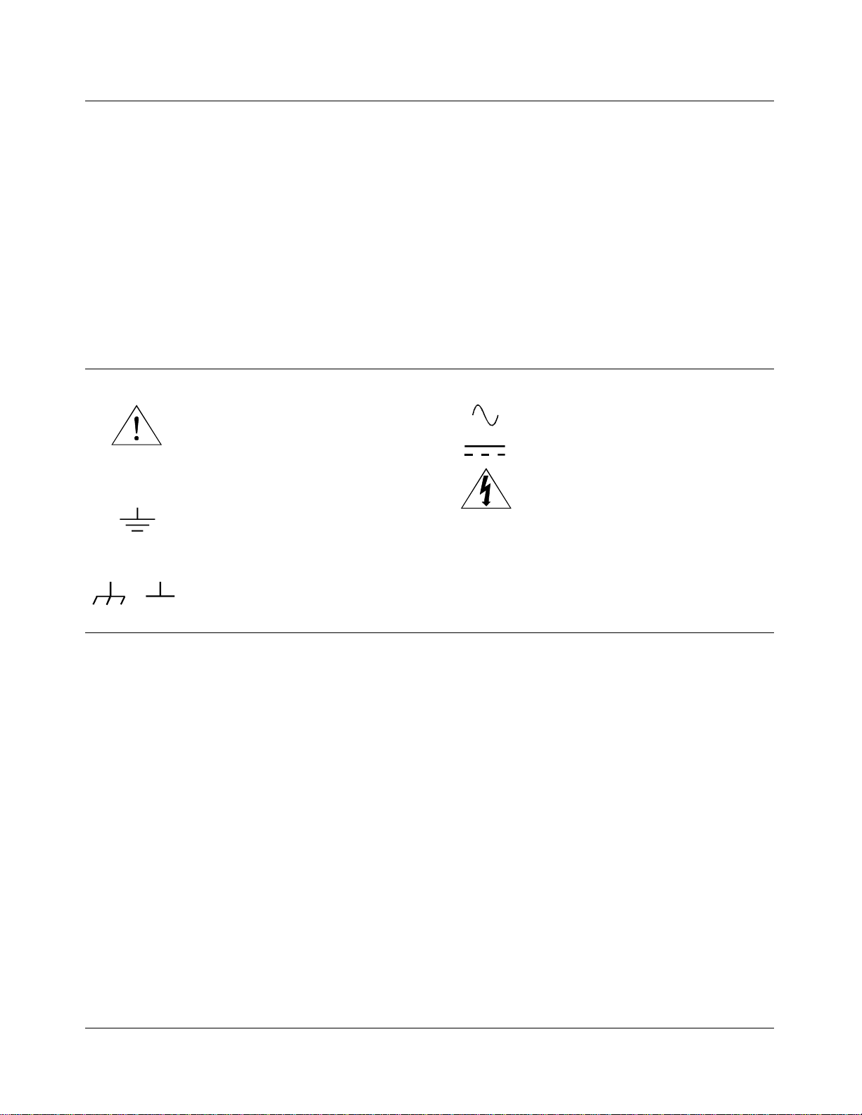
Safety Symbols
Instruction manual symbol affixed to product. Indicat es that the user must re fe r t o the
manual for specific WARNING or CAUTION information to avoid personal injury
or damage to the product.
Indicates the field wiring terminal that must
be connected to earth ground before operating the equipment—protects against electrical shock in case of fault.
Frame or chassis ground termi nal — t ypi-
or
cally connects to the equipment’s metal
frame.
WARNING
CAUTION
Alternating current (AC).
Direct curren t (DC).
Indicate s ha za rdous voltages.
Calls at te nt i on t o a pr ocedure, practi ce, or
condition that could cause bodily injury or
death.
Calls at te nt i on t o a pr ocedure, practi ce, or condition that could possibly cause damage to
equipme nt or perma nen t los s of data.
WARNINGS
The following ge ner al safet y prec aut ions mu s t be observed du ri ng al l phas es of oper ation, service, and re pai r of this product.
Failure to comply with these prec aut ions or with specific war nings elsewhe re in this manual violates safety stand ard s of design ,
manufacture, and intended use of the product. H ewl et t-Pac kard Company assumes n o liabilit y f or the cus t o mer’s fai lu re to
comply with these requirements.
Ground the equipment: For Safety Cl as s 1 equipmen t (equ ipment ha vin g a protective ea rth ter mi nal) , an unint erru ptib le sa fety earth
ground must be provide d from the ma in s power sour ce to the produ ct input wi rin g termi nals or suppli ed power cable .
DO NOT operate the produc t in an explosive at mospher e or in the presen ce of flammable gases or fumes.
For continued protect ion a gainst fire, repl ace the li ne fuse(s) only with fuse(s) of the same voltage and current rating and type .
DO NOT use repaired fuses or short-circui ted fuse holders.
Keep away from live circuits: Operatin g personnel must not remove equipment covers or shields. Procedures involving the removal
of covers or shields are for use by service-trained personnel only. Under certain conditions, danger ous voltages may exist even with the
equipment switched off. To avoid dangerous ele ctrical shock , DO NOT perf orm procedures involving cover or shield removal unless
you are qualified to do so.
DO NOT operate damaged equipment: Whenever it is possible that the safety protection feat ur es bui l t i nt o t hi s pr oduct have been im paired, either t hr ough physical dama ge, exces si ve moisture, or any other re as on, REMOVE POWER and do not use the product until
safe operation can be verified by service-trained personnel. If necessary, return the product to a Hewlett -Packar d Sa les and Se r vice Office for service and repair to ensure that safety features are maintaine d.
DO NOT service or adjust alon e: Do not attempt internal service or adjustment unless another person, capable of rendering first aid
and resuscitation, is present.
DO NOT substitute par ts or modify equipment: Because of the danger of introducing additional hazar ds, do not install substitute
parts or perform any unauth orized modifica tion to the product. Ret urn the produ ct to a Hewlett -Packar d Sa les and Ser vice O ffice for
service and repair to ensure that sa fe ty features are ma i nt ai ned.
6 HP E1351A, E1353A 16-Channel FET Multiplexer Modules User’s Manual
Page 7

Declaration of Conformity
according to ISO/IEC Guide 22 and EN 45014
Manufacturer’s Name: Hewlett-Pa ckar d C ompany
Loveland Manufacturing Center
Manufact ure r’s Addre s s: 815 14th Street S.W.
Loveland, Colorado 80537
declares, that the product:
Product Name: 16-Channel FET Mult iplexer M odule s
Model Number : E1351A, E1353A
Produc t Opt ion s: All
conforms to the following Pr od uct Spe cifi cati ons :
Safety: IEC 1010-1 (1990) Incl . Amend 1 (1992) /E N610 10-1 (1993)
CSA C22.2 #1010.1 (1 992)
UL 1244
EMC: CISPR 11:1990/EN55011 (1991): Group1 Class A
IEC 801-2:1991/ E N5008 2-1 (1 992) : 4kVCD, 8k VA D
IEC 801-3:1984/ E N5008 2-1 (1 992) : 3 V/m
IEC 801-4:1988/ E N5008 2-1 (1 992) : 1kV P ower Lin e
.
Supplementary Information: The product herewi th c omplies w it h th e requirements of the Low Voltage Directive
73/23/EEC and the EMC Directive 89/336/ EEC and carri es the CE-mark ing acc ordingly.
Tested in a typical configuration in an HP B-Size VXI mainframe.
July 20, 1995 Jim White , QA Manager
European conta ct: Your loca l He wlett-Pa cka rd Sales a nd Servi ce O ffic e or Hewlett- Packa rd GmbH, Departm ent
HQ-TRE, Herr enberger Str aß e 130, D-71034 Böbl in gen, Germany (FAX + 49-7031-14-3143).
HP E1351A, E1353A 16-Channel FET Multiplexer Modules User’s Manual 7
Page 8

Notes
8 HP E1351A, E1353A 16-Channel FET Multiplexer Modules User’s Manual
Page 9

Please fold and tape for mailing
Reader Comment Sheet
HP E1351A/53A 16-Channel FET Multiplexer Module User’s Manual
Editio n 4
You can help us improve our manual s b y sharing your commen ts and sug gesti ons. In apprec iat i on of your time, we will
enter yo u in a quarterly drawing for a Hewle tt -Pac kar d Palmt op Per s onal C omputer (U.S. government employees
cannot participate in the drawing).
Your Name
C ompany Nam e
Job Title
Address
City, State/Province
Country
Zip/Postal Code
Telephone Number with Area Code
Please list the syste m contr ol ler , oper ati ng syste m, pr ogr a m ming la ng uage, and pl ug-in modules you are using.
fold here
BUSINESS REPLY MAIL
FIRST CLASS PERMIT NO. 37 LOVELAND,CO
HEWLETT-PACKARD COMPANY
cut along this line
Measurement Systems Division
Learning Products Department
P.O. Box 301
Loveland, CO 80539-9984
NO POSTAGE
NECESSARY
IF MAILED
IN THE
UNITED STATES
fold here
Please penci l-in one circl e for each statement below: Disagree Agree
• The documentation is well organized. OOOOO
• I nstructions are easy to understand. OOOOO
• The documentation is clearly written. OOOOO
• Examples are clear and useful. OOOOO
• Illustrations are clear and helpful. OOOOO
• The documentation meets my overall expectations. OOOOO
Please write any c omments or suggestions be low--be specific.
Page 10

10 HP E1351A/53A 16-Channel FET Multiplexer Module User’s Manual
Page 11

Getting Started with the HP E1351A/53A
Using This Chapter
This chapter descr ibes the HP E1351A 16-Cha nne l FET and the
HP E1353A 16-Channe l The r mocouple FET Multip le xer Modules, and
shows how to program the modules using SCPI (Standard Co mman ds for
Programmable Instruments) commands. This chapter contains the
following sections:
• FET Multiplexer Module Description . . . . . . . . . . . . . . . . . . Page 11
• Multimet er Connectio n Points. . . . . . . . . . . . . . . . . . . . . . . . Page 12
• Switchbox & Scanning Voltmeter Configurations . . . . . . . . Page 14
• Digital Bus and Triggering . . . . . . . . . . . . . . . . . . . . . . . . . . Page 15
• Programming Language. . . . . . . . . . . . . . . . . . . . . . . . . . . . . Page 16
• Initial Operation. . . . . . . . . . . . . . . . . . . . . . . . . . . . . . . . . . . Page 16
FET Multiplexer Module Description
Chapter 1
The FET multiplexer module provides high-speed switching (multiplexing)
for up to 16 channels. The module can be used as a scanning multiplexer
for a scanning voltmeter configurat ion, or a s a st and-alone multiplexer in a
switchbox c onf igurat ion. The c hannels are numbered 00 to 15. Each
channel provides connections for High (H), Low (L) and Gua rd (G),
although only High and Low are switched. The FET multiplexer module
can switch up to 100,000 connections per second (100 K switches/sec).
The FET multip le xer module consists of a co mpo nent a s sembly and a
terminal module. There are three different terminal modules, one for each
of the following applications: HP E1351A 16-Chann el FET Multiplexer
Module, HP E1353A 16-Channel Thermocouple FET Multiplexer Module,
and HP E1352A 32-Cha nne l Single-Ended FET Mu ltip lexer Module. Th e
component assembly is the same for all three applications. For information
on the 32-Channel Single-Ended FET Multiplexer Module, see the
HP E1352A User’s Manual.
The component assembly contains the VXIbus interface, the FET switches,
the analog bus connector and the digital bus. The terminal modules prov ide
connection points for the individual channels, as well as monitoring points
for the tree terminals and the direct terminals. The FET multiplexer module
can be externally triggered from the VXIbus backplane or through the
digital bus handshake lines on the front of the component assembly.
Chapter 1 Gettin g Started with the HP E1351A/53A 11
Page 12

For high-speed operation (100 K switches/sec.) the scanning list is
automatically downloaded into RAM on the multiplexer module.
Triggering for c hannel adva nce is from the two handshake lines on the
digital bus. The scanning operation does not require any intervention from
the mainframe CPU. This only applies for switchboxes or scanning
voltmeter configurations that have all FET multiplexer modules. For a
downloaded sca n list in switchboxes, the trigger source must be
TRIG:SOUR DBUS or TRIG :S OUR IM M.
Multimeter Connection Points
There are three places where signals on a closed channel can be measured:
analog bus connector, tree terminals and direct terminals. Each of these
pro v ide s a d ifferen t c a pab i li ty for con figuri ng the modu le .
Analog Bus
Connector
The analog bus connector provides a direct connection between multiple
multiplexer modules and also b etween a mult iplexer module and HP
E1326/E1411 Multimeters. A ribbon cable is used to daisy-chain multiple
multiplexer modules together, and to connect a multimeter to the
multiplexer modules for a scanning volt meter. The
command automatically closes the appropriate tree isolation switches to
route closed channels to the analog bus. This command must be executed in
a switchbox configuration. A scanning voltmeter automatically configures
the multiplexer for the analog bus connector.
SCAN:PORT ABUS
Tree Terminals Tree terminals provide an external connection point through the terminal
modules for the signals which are on the analog bus lines. Tree terminals
are the recommended connection points for connect ing stand-alone
multimet ers and externa l curr ent sources for 4-wire resistance
measurements.
Direct Terminals The 16 channels are s epara ted into two banks, Bank 0 and Bank 1. When a
channel is closed, that channel is connec ted to a Bank Common. Channels
00 to 07 are on Bank 0 Common and channels 08 to 15 are on Bank 1
Common. The terminal module has connection point s for t he direct
terminals, where you can measure signals on the respective Bank
Commons. The ban ks can be isolat ed from each other, from the analog bus
connector, and from the tree terminals with the A and B tree isolation
switches.
12 Getting Started with the HP E1351A/53A Chapter 1
Page 13
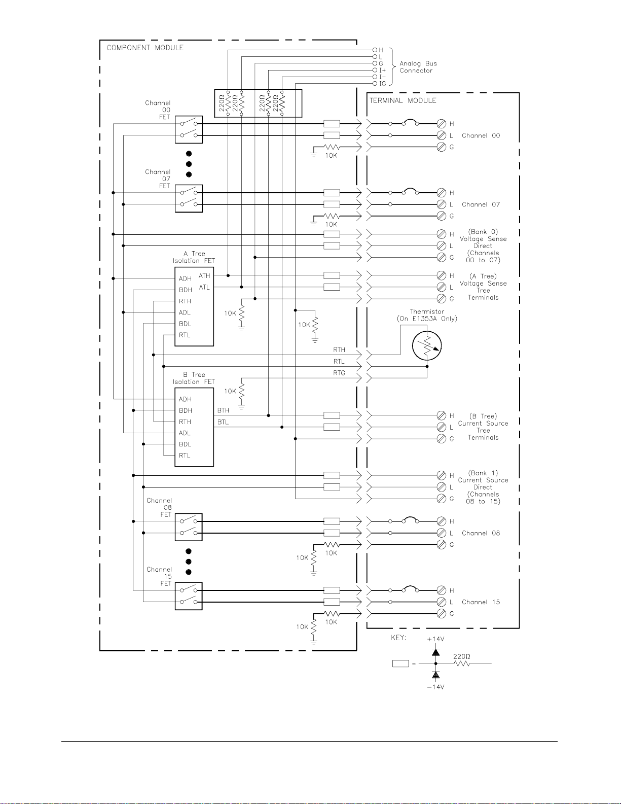
Figure 1-1. FET Multiplexer Module Block Diag r am
Chapter 1 Gettin g Started with the HP E1351A/53A 13
Page 14

Switchbox and Scanning Voltmeter Configurations
A VXIbus instru ment is a modu le or group of modules which p erform a
specified fu nct ion. For the HP E1300/01 m a inframe, the first module in an
instrument must have a logical address which is evenly divisible by 8 (16,
24, 112), and the rest of the module s in t he ins tr ument are nu mbered
consecutively. The instrument’s secondary address is the whole number
equal to the logical address divided by 8 (for a logical address of 16, 17,
18,…23, the secon dary add r ess is 02). For instru ment definition in o ther
mainframes, s ee the mainfra me manual. If an instrument c onsists of onl y
multiplexer modules, it is a switchbox configuration. If a multiplexer
module(s) is comb ined with a mult imeter to form an instrument, that is a
scannin g voltme ter configurat ion.
Switchbox A switchbox is a multiplexer module or group of multiplexer modules
which form a single instrument. A switchbox can be connected to a
mu ltimeter whi ch i s a d iff erent V XIbu s in str umen t , t o a n HP-I B
multimeter, or to a stand-alone multimeter. The switchbox and the
multimeter have different secondary addresses. Separate configuration
commands m ust be sent to the switc hbox and to the multimet er. The
follo wing progra m illustrates the differe nt a ddre sses and the configuration
commands requ ired. The HP-IB interface select code is 7, and the
mainframe address is 09. The multiplexer has an instrument address of 24,
so its secondary address is 03. The multimeter is HP-IB controlled, and has
a primary ad dress of 22.
1
controlled
10 OUTPUT 722;"T RIG EXT;DC 10" !Sets multimeter to external trigger
and to measure DC volts
20 OUTPUT 70903;"OUTP ON" !E nab les "Trig Out" port
30 OUTPUT 70903;"TRIG:S OUR BUS" !Sets switch box to recei v e B u s
40 OUTPUT 70903;"SCAN:MO DE VO LT "!Set up switchbox for voltage
50 OUTPUT 70903;"SCAN:PO RT ABUS"!C lose s th e appropri at e tree
60 OUTPUT 70903;"ARM:COUN 2" !Set for two cycles through the
70 OUTPUT 70903;"SCAN (@100;115)"! Se le c ts th e c hannel list. 100
80 OUTPUT 70903;"INI T " !Close first c hannel to start
90 FOR I = 0 TO 15 !Start count loop
100 ENTER 722;A !Enter re adi ng i nto vari abl e A
110 PRINT A !Print reading in variable A
trigger s
measurements
isolat io n switche s while scanning,
automatical ly makes conne ction to
the analog bus and tree termi nal s.
scan list
selects fi rst chan ne l on card 1;
115 selects last cha nne l on card 1
scanning c ycl e
1 HP-IB is Hewlett-Packard ’s implem entat ion of IEEE Std 48 8.1-1 978
14 Getting Started with the HP E1351A/53A Chapter 1
Page 15

120 TRIGGER 70903 !Trigger the s witchbox to advance
the channel list
130 NEXT I !Inc r ement count
140 END
Scanning Voltmeter When the mu ltiplexer(s) is combined with a multimeter to for m a single
instru ment, they become a virtual instrument, a scanni ng volt meter. The
multiplexer(s) and the multimeter have the same secondary a ddress. Th e
multimeter automatically configures the multiplexer, so the
SCAN:PORT and TRIG:SOUR commands are not required. Channel
advanc e is from the digita l bus ha ndshake lines, s o the count loop is not
required. The
ARM:COUN command does not apply to do wnloaded scan
lists, so you cannot specify the number of cycles through the scan list. You
can, howev er, specify
INIT:CO NT ON for continuous scanning through the
scan list.
10 DIM Rdgs(1:16) !Dimension an array for 16
readings
20 OUTPUT 70903;"*RST" !Reset instrument
30 OUTPUT 70903;"MEAS:VOLT :DC? (@100: 115)"
40 ENTER 70903;Rdgs(*) !Enter readings into array
50 PRINT Rdgs(*) !Print results
60 END
!Configure instrument
SCAN:MODE,
Digital Bus and Triggering
The HP E1351A/E1353 A can be trig gered f or channel advance from the
VXIbus backplane or through the digital bus handshake cable on the front
of the component assembly. Backplane triggering can come from HP-IB
comput er commands over the HP-IB Bus or from th e HP E1300/1301
Mainframe "Event In" port. Digital bus triggering uses two handshake
lines; channel advance and channel closed. Channel advance (input to
multiplexer) triggers an advanc e, and channel closed ( output from
multiple xer) signif ies a dva nce completed.
The HP E1326B Mu ltimeter has a digital bus port on t he face plate, and
connects to the multiplexer with th e digital bus cable (see Figures 2-10 and
2-11). To connect other multimeters for digital bus trigg ering, you must
prepare a custom cable. Use a connector like the one on the digital bus
cable (HP part nu mber E1300-61611 ). C onnect the measureme nt complete
port from the multimeter to the channel advance pin, and the external trigger
to the channel closed pin. Conn ect the grounds for both signals to the
digital bus ground (second pin from right). You can use this cable to
connect an external multimeter to a switchbox, and then use
(digital bus triggering). You can also order a custom cable with
DBUS
BNC to digital bus c onnectors, HP part number E1411-80001. See Figure
2-11 for more information on multiplexer-to-multiplexer and
multiplexer-to-multimeter connections.
TRlG:SOUR
Chapter 1 Gettin g Started with the HP E1351A/53A 15
Page 16
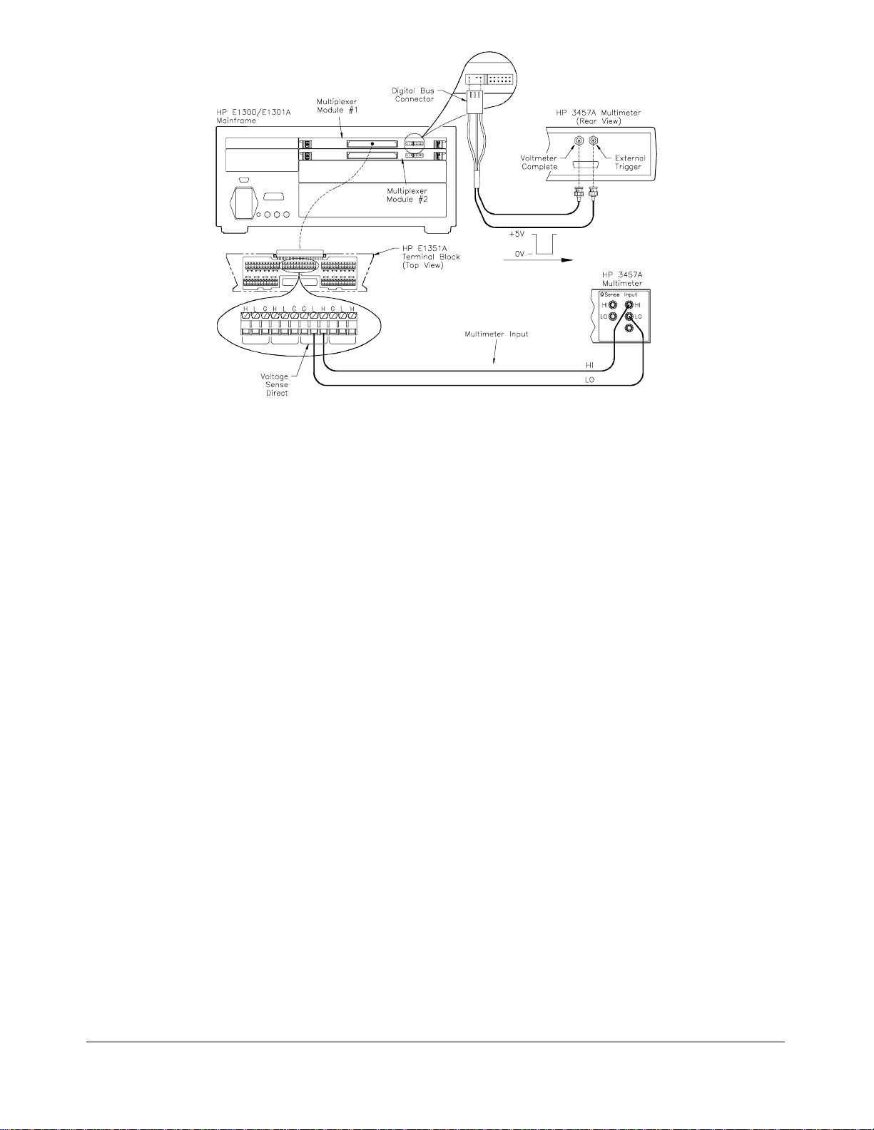
Figure 1-2. Custo m Cable fo r Dig ital Bus Trig geri n g
Programming Language
The examples in this manual use the Standard Commands for
Programma b le I nstruments (SCPI) commands, H ewlett-Packard BASIC and
an HP 9000 Series 200/ 300 c omputer over the HP-IB. Chapter 5 contains
information on SCP I c ommand f orm at . Appendix B contains details o n the
registers f or regis t er-based programming.
Initial Operation
Use the following program to verify initial multiplexer operation by closing
a channel and querying channel closure. The computer interfaces to the
mainframe with the Hewlett-Packard Interface Bus (HP-IB). The HP-IB
interface select code is 7, and the mainframe address is 09. The multiplexer
has an instrume nt addre ss of 24, s o its seco ndar y ad dress is 03.
This example first resets the switchbox and then closes channel 02 of a
single multiplexer module (card number 1) in the switchbox. The program
next queries the channel closure state. A returned "1" shows that the
channel is closed, a returned "0" designates an open channel.
10 OUTPUT 70903;"*RST" !Opens all channe ls
20 OUTPUT 70903;"CLOS (@102)" !Close channel 02 on c ard 1
30 OUTPUT 70903;"CLOS? (@102)" !Query ch annel 02 state
40 ENTER 70903;Value !Enter re sul ts in to vari abl e cal le d
Value
50 PRlNT Value !Display resul t
60 END
16 Getting Started with the HP E1351A/53A Chapter 1
Page 17

Configuring the HP E1351A/53A FET
Using This Chapter
This chapter shows how to configure the 16-Channe l F ET Multiplexer
Modules, how to connect external wiring and how to connect multimeters.
This chapter contains the followi ng s ections:
Chapter 2
Multiplexer Modules
• Warnin gs and C aut ions . . . . . . . . . . . . . . . . . . . . . . . . . . . . . Pag e 17
• Multiplexer Card Nu mber s . . . . . . . . . . . . . . . . . . . . . . . . . . Page 18
• Selecting the Interrupt Line Number . . . . . . . . . . . . . . . . . . . Page 20
• Setting the Card ID Switch . . . . . . . . . . . . . . . . . . . . . . . . . . Page 21
• Connecting User Inputs . . . . . . . . . . . . . . . . . . . . . . . . . . . . . Page 22
• Adding Signal C o nditioning Co mponents/Current
Shunts . . . . . . . . . . . . . . . . . . . . . . . . . . . . . . . . . . . . . . . Page 23
• Connecting Field Wiring . . . . . . . . . . . . . . . . . . . . . . . . . . . . Page 24
• Wir ing a Termin al M odu le . . . . . . . . . . . . . . . . . . . . . . . . . . Page 25
• Connecting Multime ters and Signal Generators . . . . . . . . . . Page 26
• Analog Bus and Digital Bus Cables . . . . . . . . . . . . . . . . . . . Page 27
Warnings and Cautions
Warning SHOCK HAZARD. Only service-trained personnel who are
aware of the hazards involved should install, remove, or
configure the multiplexer modules. Before you install any
module, disconnect AC power from the mainframe and from
user wiring.
Caution MAXIMUM VOLTAG E/CU RRENT. The maximum volt age that
may be applied between High (H), Low (L), and Guard (G)
terminals is 15 V dc or 10.6 V rms (15 V peak). The maximum
current is 1 mA per channel.
STATIC ELECTRICITY. Static electricity is a major cause of
component failure. To prevent damage to the electrical
components in the multiplexer module, observe anti-static
techniques whenever removing a module from the mainframe
or whenever working on a module.
Chapter 2 Configuring the HP E1351A/53A FET Multiplexer Modules 17
Page 18
Multiplexer Card Numbers
HP plug-in modules installed in an HP VXIbus mainframe are treated as
independent instruments each having a unique secondary HP-IB address.
An instrument may be composed of a single plug-in module or multiple
plug-in modu les. The card nu mber identifies the m odule w ithin a
switchbox or scanning voltmeter configuration. The multiplexer module
with the lowest logical addr ess is al ways card nu mber 01. The multiple x er
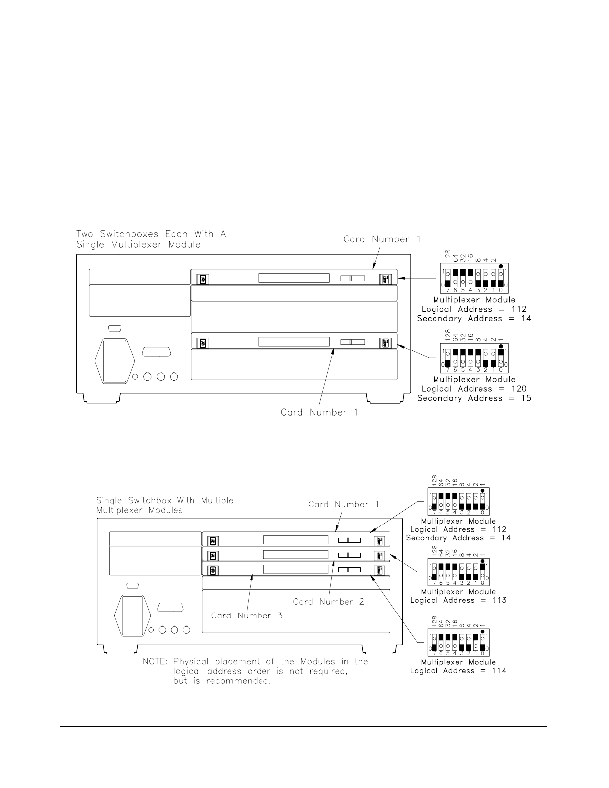
module with the next successive address is 02, and so on. Figure 2-1
illustrat es the card numbers and logical addresses o f typical single-module
switchb ox es. Figure 2-2 illustrates the card numbers and logical address es
of a typical multiple-module switchbox. Figure 2-3 illustrates the card
numbers and logical addresses of a typical multiple-module scanning voltmeter.
Figure 2-1. Card Numbers for Sing le- Mod ule Switch b oxes
Figure 2-2. Card Numbers for Mu ltip le-Mo d ule Switch box
18 Configuring the HP E1351A/53A FET Multiplexer Modules Chapter 2
Page 19
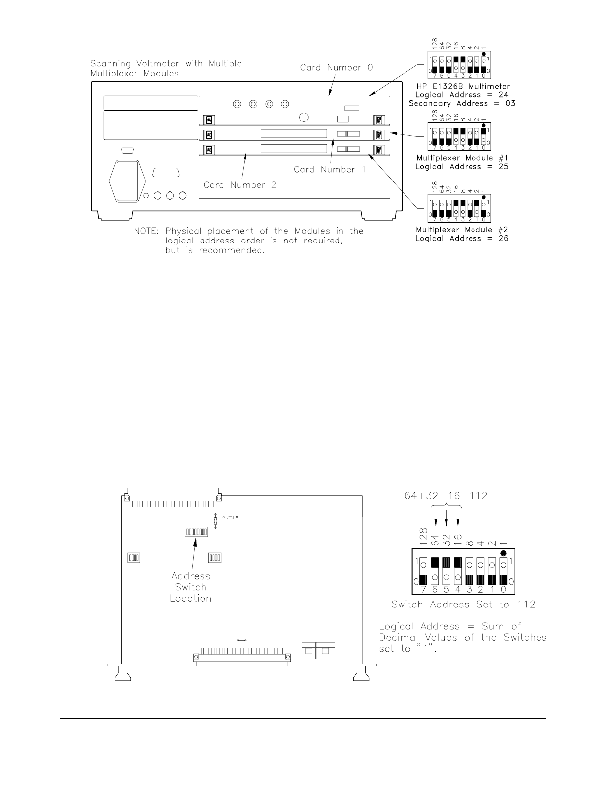
Figure 2-3. Card Numbers for Scanning Voltmeter
The logical addres s es no ted in Figures 2-1, 2-2, and 2-3 a pply to modules
installed in an HP 75000 Series B M a inframe (HP Model Number
E1300A/E130 1 A) or i n a mainframe with an HP E1405/140 6 C omma nd
Module. See the HP 75000 Series B Installation an d Getting Start ed Guide
or the appropriat e HP Command Module Manual for more information on
switchboxes and scanning voltmeter configurations, and logical addressing.
For uses i n ot her systems or mainframes, see the appropriate manuals.
Setting the Address
Switch
The logical address switch (LADDR ) factory setting is 112. You may have
changed the switch setting during module installation. Valid address values are
from 1 to 255. Refer to the HP 75000 Series B System Installation and Getting
Started Guide or the appropriate HP Command Module Manual for addre ss in g
information. O therwise, refer to Figu re 2 - 4 to reset th e factory se t ting.
Figure 2-4. Setting the Logical Address Switch
Chapter 2 Configuring the HP E1351A/53A FET Multiplexer Modules 19
Page 20
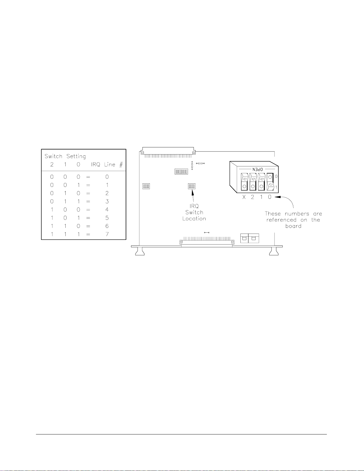
Selecting the Interrupt Line Number
The multiplexer module generates interrupts at the end of a downloaded
scan list. The interrupt li ne number switch determines which backplane
IRQ lin e will be us ed. Different mainframes an d resource mana ge r s
recog niz e differ en t backplane IRQ lin es. The int errupt line number mu st be
set to the line number your system is programmed to recognize. Refer to
your mainframe manua l.
Refer to Figure 2-5 t o c hange t he int errupt lines. Valid line numbers are
from 1 to 7. Set the interrupt line number to the mainframe interrupt
handler numb er.
Figure 2-5. Setting the Interru pt Line Numb er
20 Configuring the HP E1351A/53A FET Multiplexer Modules Chapter 2
Page 21
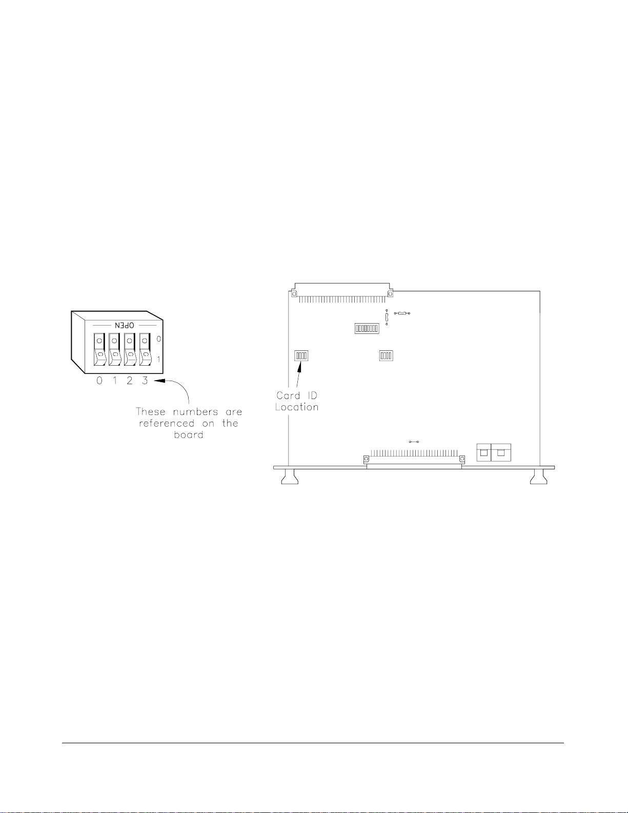
Setting the Card ID Switch
The multiplexer module can be an HP E1351A, HP E1352A or HP E1353A
depending on which terminal module is installed. With a normal
connection, the terminal module will automatically configure the module
for the appropriate model. To ide nt i fy a module with out a terminal module,
set the Card ID switch as shown in Figure 2-6. The ID numbers are:
Model Value Configuration
HP E1351A 0 all pins open
HP E1352A 8 pin 3 closed
HP E1353A 2 pin 1 closed
For nor mal connections, leave the switch at the factory settin g which is all
pins open.
Figure 2-6. Card ID Switch
Chapter 2 Configuring the HP E1351A/53A FET Multiplexer Modules 21
Page 22
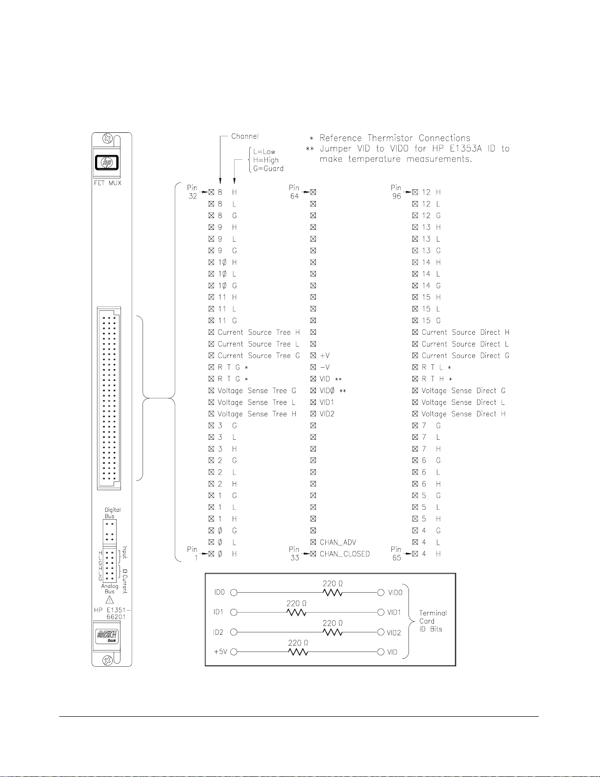
Connecting User Inputs
The 16-Channel FET consists of a component module and a terminal
module. If the terminal module is not desired, F igure 2-7 shows the front
panel and the module’s connector pin-out which mates to the terminal
module.
Figure 2-7. 16-Channel FET Multiplexer Con nect or Pin-out
22 Configuring the HP E1351A/53A FET Multiplexer Modules Chapter 2
Page 23
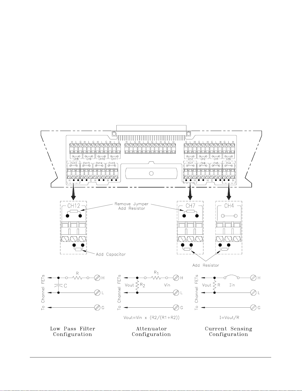
Adding Si gn al Conditioning Compone nt s/ C ur ren t Shunts
The multiplexer module’s terminal module allows you to add components
on each channel for the following:
– Low-Pass Filters
– Attenuators
– Current Shunts (for current measurements using a voltmeter)
Figure 2-8 shows how to install the appropriate components for the above
configurations. In the figure, channel 12 shows a low pass filter
configuration, channel 07 an attenuator configuration, and channel 04 a
current shunt configuration.
Figure 2-8. Signal Conditio ning Compo nents/ Cu rrent Shunt s
Chapter 2 Configuring the HP E1351A/53A FET Multiplexer Modules 23
Page 24
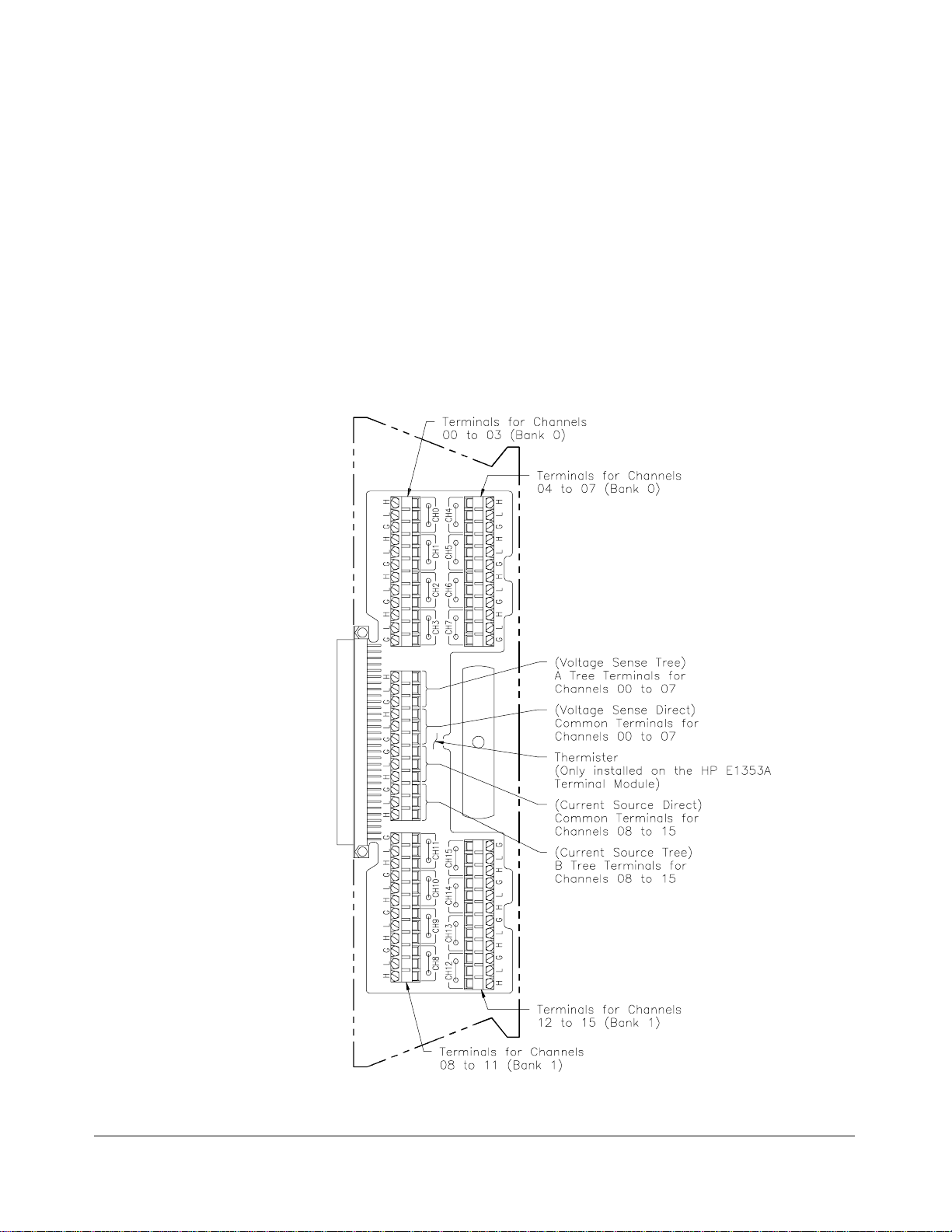
Connecting Field Wiring
Leads for the individual channels are connected through the channel
terminals on the terminal modules. Multimeters and signal generators can
be connected to the di rect terminals or tree terminals on the terminal
modules. Figure 2-9 shows the terminal module channel terminals for the
16-Channel FET Multiplexer Module (HP E1351A) and the 16-Channel
Thermocouple FET Multiplexer Module (HP E1353 A).
Wiring Guidelines • If possible, use shielded cables with the shields connected to the Guard
(G) terminals and to the low connection near the measurement point.
• Be sure the wires ma ke good connectio ns on t he screw terminals.
• For thermocouples, connect the Guard terminal to the
thermocouple’s shield lead and the low connection near the
measurement poi nt.
Figure 2-9. FET Multiplexer Modules T ermin al Modu le
24 Configuring the HP E1351A/53A FET Multiplexer Modules Chapter 2
Page 25
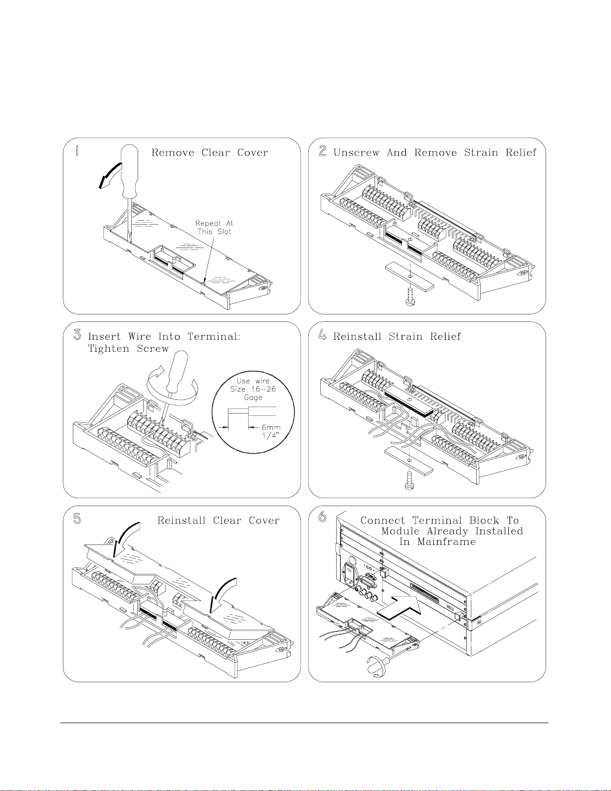
Wiring a Terminal Module
The following illustra tions show how to connect field wiring to the terminal
module.
Chapter 2 Configuring the HP E1351A/53A FET Multiplexer Modules 25
Page 26
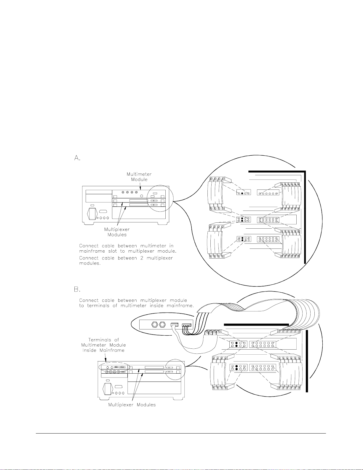
Connecting Multimeters and Signal Generators
Figure 2-10 shows h ow to connect t he ana log bu s connector and the digital
bus handshake cable between multiple multiplexer modules and the HP
E1326B Multi meter. Use the cables shipped with the multiplexer modules
to make the connections.
Stand-alone multimeters and signal generators can also be connected to the
tree terminals or the direct terminals. Connections to the tree terminals and
the direct terminals are made on the terminal modules. If the multimeter
has "V olt meter Compl ete" and "Externa l Trigger" po rts that u se an open
collector TTL pulse, you can use a custom cab le t o c onnect it to the digital
bus for triggering (see “Digital Bus and Triggering” in Chapter 1).
Figure 2-10. Anal o g Bus and Digital Bus Conn ectio n s
26 Configuring the HP E1351A/53A FET Multiplexer Modules Chapter 2
Page 27
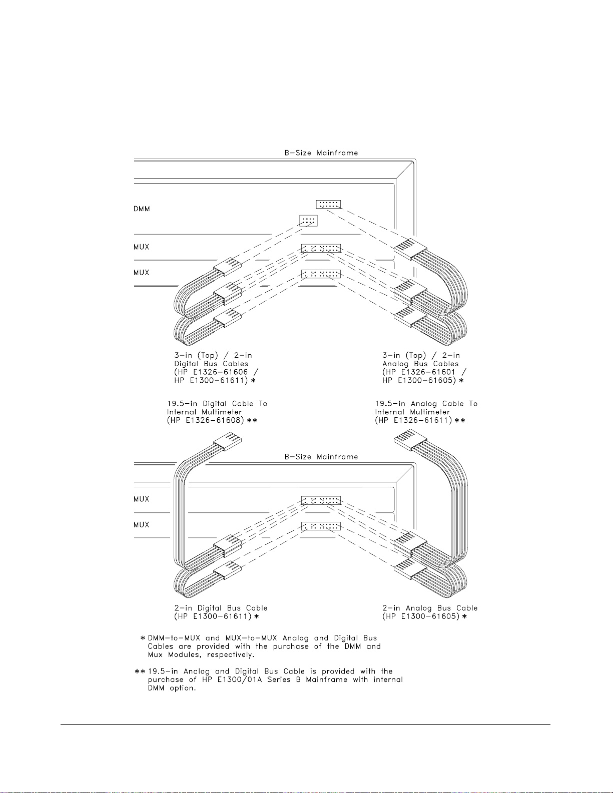
Analog Bus and Digital Bus Cables
Figure 2-11 shows analog bus and digital bus cables for
multiplexer-to-multiplexer and multiplexer-to-multimeter connections.
Figure 2-11. Analog Bus an d Digi tal Bus Cab les
Chapter 2 Configuring the HP E1351A/53A FET Multiplexer Modules 27
Page 28

Notes
28 Configuring the HP E1351A/53A FET Multiplexer Modules Chapter 2
Page 29

Chapter 3
Using the HP E1351A/53A FET Multiplexer
Modules
Using This Chapter
This chapter uses some typical examples to show how to use the
16-Channel FET and 16-Channel Thermo couple FET Multiplexer Modules.
Refer to Chapter 4, “Understanding the HP E1351A/53A FET
Multiplexers” for further information. This chap t er c ontains the following
sections:
• Selecting Channels. . . . . . . . . . . . . . . . . . . . . . . . . . . . . . . . . Page 29
• Multiplexer Commands . . . . . . . . . . . . . . . . . . . . . . . . . . . . . Page 31
• Connecting Switchbox Channels to Direct
Terminals . . . . . . . . . . . . . . . . . . . . . . . . . . . . . . . . . . . . Page 32
• Connecting Switchbox Channels to Tree Terminals for
Making M e asurement s. . . . . . . . . . . . . . . . . . . . . . . . . . Page 34
• Scanning a Range of Switchbox Channels . . . . . . . . . . . . . . Page 36
• Dow nl oadin g a Sc an List. . . . . . . . . . . . . . . . . . . . . . . . . . . . Page 39
• Scanning a Switchbox without a Downloaded
Scan List . . . . . . . . . . . . . . . . . . . . . . . . . . . . . . . . . . . . . Page 40
• Scanning a Switchbox with a Downloaded
Scan List . . . . . . . . . . . . . . . . . . . . . . . . . . . . . . . . . . . . . Page 41
• Scanning Voltme ter Configuration with
HP E1326B. . . . . . . . . . . . . . . . . . . . . . . . . . . . . . . . . . . Page 42
• Measur i ng T e mp erature Usi ng Thermocou ples
(HP E1353A Module only) . . . . . . . . . . . . . . . . . . . . . . Page 43
Selecting Channels
Individual channels within a module or multiple-module instrument are
selected with the
channel_list> commands. OPEN and CLOSe <channel_list> immedia tely
<
opens/clos es the specified channel. The
creates a scann ing list which can be downloaded into RAM on each module.
INITiate command clos es the first channel on th e scan lis t, and th e
The
selected trigger mode advances the rest of t he c hannels.
The FET Mul tiplexer M odule uses brea k-bef ore-make logic so th at a c losed
channel is open ed before the next channel is closed. O nly one channel can
be closed at any given time on the FET multiplexer. The only exception is
SCAN:MODE FRES (4-wire resistance measurements). You can,
in
however, have a channel closed on two different modules in the same
instrument.
Chapter 3 Using the HP E1351A/53A FET Multiplexer Modules 29
SCAN <channel_list> or OPEN and CLOSe
SCAN <channel_list> command
Page 30

To address specific channels within a multiplexer module in a switchbox or
scannin g voltme ter configuration, you mus t send the appropriate SCPI
command string with a specified card number (cc) and channel number
(nn). The card number refers to the multiplexer module within a switchbox
or scanning voltmeter configuration. The multiplexer module with the
lowest logical address in a VXIbus instrument is card number 01, and the
next consecutively numbered multiplexer module is card number 02. If you
have more than one switchbox or scanning voltmeter configuration, the card
numbering s equence starts at 01 for eac h c onf igurat ion. A channel address
is, therefore, a four digit number (ccnn). For channel 07 on card 02 the
address is 0207. You can delete leading zeros, so 207 is also a valid
channel address. The channel address
<channel_list> is in the form:
• (@ccnn) for a single channel;
• (@ccnn,ccnn) for multiple channels;
• (@ccnn:ccnn) for sequential channels;
• (@ccnn:ccnn,ccnn:ccnn) for groups of sequential channels.
OPEN and CLOSe commands should only be used with th e
The
single-channel format and for one unique application of the
multiple-channel format. You can close a channel on tw o different cards in
the same instrument (e.g., 102 a nd 208) at the same time. You cannot close
two channels on the same card at the same time (102 and 108). Closing a
channel automatically opens all other channels on that card.
CLOSe (@102,208,309) Closes 02 on card 1, 08 on card 2
and 09 on card 3.
CLOSe (@103,204) Opens 102 and 208, clo ses 10 3 and
204; 309 left closed.
30 Using the HP E1351A/53A FET Multiplexer Modules Chapter 3
Page 31

Multiplexer Commands
The following commands are c overed in Chapter 3. For a complete list and
description of commands see Chapter 5, “Command Reference”.
Table 3-1. Matrix Command s Used in Chapter 3
Command Descriptio n
ARM:COUNt <
INITiate[:IMMediate]
INITiate: CO NTi nu ous <
mode> = 1 | 0 | ON | OFF
<
[ROUT e : ] CLOS e <
[ROUT e: ]C L O Se? <
[ROUTe:]OPEN <
[ROUTe:]SCAN <
[ROUTe:]SCAN: MO DE FRES Closes paired channel relays (fo r examp le, ch annels 01 and 09)
[ROUTe:]SCAN:PO RT ABUS Automatically closes the tree isolation switches.
TRIGger[:IM Mediat e]
TRIGger:SOURce <
source> = EXT | BUS | DBUS | IMM
<
number> Selects number of scan ning cyc les fo r a switchbo x only. Does not
apply to download ed scan li sts.
Channel advance for TRIGger:SOURce BUS | HOLD.
mode>
channel_l ist >
chan ne l_l ist >
channe l_list>
channe l_list>
source>
NOTE: The comm ands with brackets ([ ]) are implied and are not sho wn in this chapt er .
Enables/dis abl es cont inuous scann ing cycl es .
Closes specified chan n els.
Queries mainframe for channel clos ure.
Opens specified channels.
Closes all channels in chann el list one at a time. Previous channel
opens before n ext chan n el closes.
during 4-wir e ohms measu r emen ts .
Channel advance for TRIGger:SOURce BUS | HOLD.
Selects the trigger source as EXTernal, HP-IB BUS, Digital BUS,
or IMMed i ate.
Chapter 3 Using the HP E1351A/53A FET Multiplexer Modules 31
Page 32

Connecting Switchbox Channels to Direct Terminals
The direct terminals pr ovide direct acc ess to c losed c hannels. There is a
direct terminal f or eac h bank, Bank 0 and Bank 1. Closing any channel in
Bank 0 (c hannels 00 to 07) connects the channel to the Bank 0 dir e c t
terminal. Closing any channel in Bank 1 (channels 08 to 15) connects the
channel to the Bank 1 direct terminal. You can isolate the two banks from
each other, and from the analog bus connector and tree terminals, with the
SCAN:PORT NONE command. This command op ens the A and B tree
isolation switc hes. Figu re 3-1 shows how to connect channels 02 an d 09 of
a single modul e to their respectiv e direct terminals. Only one channel can
be c losed a t a time.
SCAN:PORT NONE Opens Tree Isolation S witches.
CLOSe (@102) Closes channel 02 on card 01.
CLOSe (@109) Opens 02 the n close s 09.
Figure 3-1. Connecti n g Channel s 02 and 09 to their Respect ive
Direct Terminals
32 Using the HP E1351A/53A FET Multiplexer Modules Chapter 3
Page 33

Comments Isolation. The direct terminals pr o vide a more accur at e measurement than
the tree terminals or the analog bus connector as the signal does not have to
travel through the extra FET switches. The
opens the tree isolation switches and isolates the direct terminals from the
tree terminals and the analog bus connector.
SCAN:PORT NONE command
The default valu e of
have not specified a different
SCAN:PORT is NO N E for reset and power-on. If you
SCAN:PORT since reset or power-on, you do
not need to execute this command. You can also use the direct terminals
SCAN:PORT ABUS. The signal for a given closed c hannel will t he n
with
be available at the direct terminal for that bank, the A tree terminal and the
analog bus co nnect or.
Closing Channels. The FET multiplexer module only allows one channel
per card to be closed at a time, except for
SCAN:MODE FRES (4-wi re
resistance measurements) where two channels are closed. You can close a
channel on two different cards in the same instrument at the same time.
SCAN <channel_list> comma nd a llow s you to specify a list of channels
The
to be closed s equen tially. The FET multiple xer module uses a
break-before-make procedure, so closed channels are opened before the
next one on the list is closed. The channels are advanc ed acc ording to the
TRIGge r mode selected.
Query Open/Closed Channels. Th e
channel_list> c ommands determine if the channel(s) in the channel list are
<
CLOSe? <channel_list> and OPEN?
open or closed, res pectively. (The query c ommand does not determine if, in
the event of a hardware failure, the channel remains open/closed.) For
example, to determine if channel 109 is closed, execute:
CLOS? (@109)
A response of "1" indicates th e channel is c lo sed, and a "0" ind icat es the
channel is open. The reverse is true for the
OPEN? <channel_list >
command. Th e response for the OPEN? and CLOSe? comman ds are:
CLOS? 1 = Closed
0 = Open
OPEN? 1 = Open
0 = Closed
To find out which c hannel on a card is closed, use a channel list for the card.
CLOS? (@100:115)
and enter the response into a string variable. If channel 09 is closed, the
response will be:
0,0,0,0,0,0,0,0,0,1,0,0,0,0,0,0
NOTE: You must read the response after sending a query command or
the switchbox will generate an error.
Chapter 3 Using the HP E1351A/53A FET Multiplexer Modules 33
Page 34

Connecting Switchbox Channels to Tree Terminals for
Making Measurements
Connect external multimeters to the A tree terminal. The SCAN:PORT
command closes the appropriat e FETs on the A and B tree isolation
ABUS
switches, so that the channels that are closed are connected to both the
analog bus connector and the tree terminals. The A tree terminal is
connect ed to the H, L, and G lin es, and t he B tree terminal is con nected t o
the I +, I- and G lines. Figure 3-2 shows how to connect multime t ers to
measure channel 02 and channel 09.
SCAN:PORT ABUS Enables tree i sola tion switches.
CLOS (@102) Close channel 02 on card 01.
CLOS (@109) Open 02, close 09.
Figure 3-2. Closing Channels 02 and 09 for a Voltage Measurement
34 Using the HP E1351A/53A FET Multiplexer Modules Chapter 3
Page 35
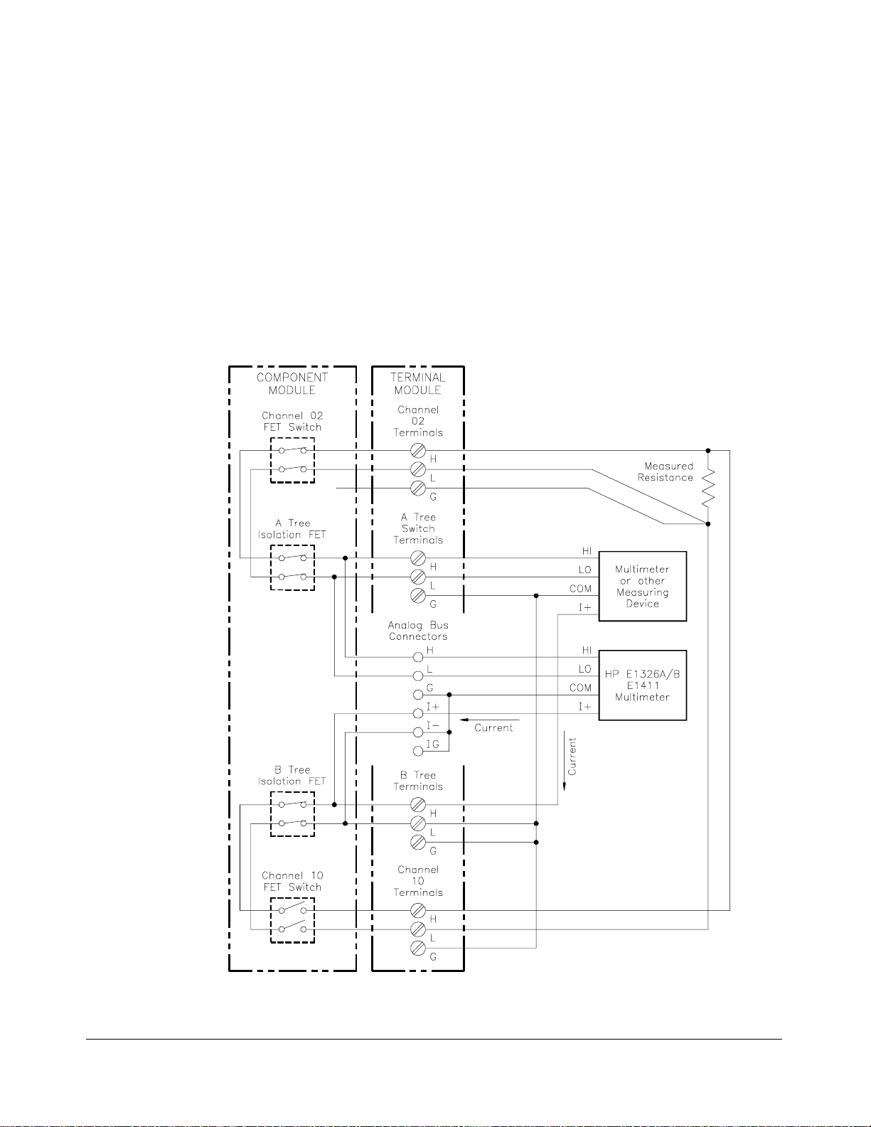
Example: Connect
Channels 02 and 10 to
Tree Terminals for
4-Wire Ohms
Measurement
The SCAN:MODE FRE S command separates Bank 0 and Bank 1 for 4-wire
resistance measurements or other stimulus/response testing. Current or
signals are connected to the B tree terminal and go out through a channel on
one bank. The voltage signal response comes in through a channel on the
other bank and goes to the A tree terminal and the analog bus connector.
The current source and voltage response must be on channels that are eight
numbers apart (f or examp le, 02 an d 10, 15 and 07). You only need to
specify the channel that the voltage reading is on as the FET multiplexer
automatically closes the corresponding channel eight numbers away. Figure
3-3 shows a current source on channel 10 and the voltage reading on
channel 02.
SCAN:MODE FRES Isolates B ank 0 fro m Ban k 1.
CLOSe (@102) Closes channels 02 and 10. 02 is
routed to A tree termina l and 10 is
routed to B tree termina l.
Figure 3-3. Connecting Channels 02 and 10 for 4-Wire Ohms Measurement
Chapter 3 Using the HP E1351A/53A FET Multiplexer Modules 35
Page 36

Scanning a Range of Switchbox Channels
You can scan a ran ge of channels o f a s witchbox consisting of single or
multiple multiplexer modules. Scanning involves sequentially closing each
channel on a range of specified channels. The selected
determines when the channel closure will advance. During scanning, the
FET which was previously closed opens before the next FET closes.
TRIGge r m ode
Example: Maki ng
Voltage Measurements
by Scanning
You can use any of th e
TRIGger:SOURce EXTernal requires an external trigger source to be connected
TRIGger mo des to advance the channel list.
to the HP E1300/1301 Mainframe "Event In" port. For computer controlled or
HP-IB triggering (
OUTput ON command enables the mainframe’s "Trig Out" port to synchronize
multimeters when not in the
For the fastest scan rat e (up to 100 K switc hes/sec.) use
. Use a custom cable (see “Digital Bus and Triggering” on page 15)
DBUS
TRIGger or *TRG) use TRIGger:SOU Rce BUS. The
TRIGger:SOURce DBUS | IMM modes.
TRIGger:SOURc e
to connect the multimeter handshake lines (Voltmeter Complete and
External Trigger) to the multiplexer digital bus.
Figures 3-4 and 3-5, and the following commands, show how to make
voltage measurem e nts by p erforming a singl e scanning cycle of all channels
on two multiplexer modules in a single switchbox. In the example, the:
• A Tree Terminals of each terminal module connect to each other and
to the multimeter in Figure 3-5. To connect the A tree terminals to
each other, use either the analog bus cables (shown in Figures 2-10
and 2-11) or wire the terminals together between the terminal
modules.
• HP-IB Bus trigger co mmand advances the switchbox channel list.
• HP E1300A/E1301 A Main frame’s "Trig Out" pulse synchron izes the
switchbox with the multimeter.
• Multimeter HP-IB select code is 7 and primary address is 22.
• Switchbox HP-IB select code is 7, the HP-IB primary address is 09,
and the HP-IB secondary address is 14.
• Computer is an HP Serie s 200/300 Comput er w ith HP BASIC using
HP-IB.
Enter and Execute:
10 OUTPUT 722;"T RIG EXT;DC 10" !Sets mu ltime te r to exte rna l
triggers and to measure dc volts
20 OUTPUT 70914;"OUTP ON" !E nab les "Trig Out" port
30 OUTPUT 70914;"TRIG:S OUR BUS" !Sets switch box to receiv e bu s
trigger s
40 OUTPUT 70914;"SCAN:MO DE VO LT "!Se t up switchbox to measure
voltage
50 OUTPUT 70914;"SCAN:PO RT ABUS"!C lose s th e appropri at e tree
isolat io n switche s whil e scan ning;
automatical ly makes conne ction to
the analog bus and tree termi nal s.
36 Using the HP E1351A/53A FET Multiplexer Modules Chapter 3
Page 37

60 OUTPUT 70914;"SCAN (@100:215)"! Sele cts th e channe l list; 100
selects th e first channe l of module
#1 and 215 selec ts t he last channel
of module #2.
70 OUTPUT 70914;"INI T " !Close first c hann el to start t he
scanning c ycl e
80 FOR I = 1 TO 32 !Start count loop
90 ENTER 722;A !Ent er reading into vari abl e A
100 PRINT A !Print reading in variable A
110 TRIGGER 70914 !Trigger the s witchbox to advance
120 NEXT I !Inc r ement count
130 END
the scan l ist
Figure 3-4. Scanning Chan nels 100 to 215 of a Two- Mod ule Switch b ox
Chapter 3 Using the HP E1351A/53A FET Multiplexer Modules 37
Page 38

Figure 3-5. Mainframe to Multimeter Connection for Synchronization
Example: Maki ng
2-Wire Ohms
Measurements by
Scanning
Example: Maki ng
4-Wire Ohms
Measurements by
Scanning
Use the same setup shown in the first progra m example in t his section,
except the current source from the multimeter must be c onne cted to the B
tree terminal. Change the commands in lines 10 and 40 to the following:
10 OUTPUT 722;"TRIG EXT;OHM" !Set multimeter to 2-wire ohms
40 OUTPUT 70914;"SCAN:MO DE RES"!Closes the appropriate tree
isolat ion s witches
This command, when used with SCAN:PORT ABUS and SCAN <channel_list>
commands, automatically closes the chann els defined in the channel list, along
with the appropriate tree isolation switches. The current source is
superimposed on the channel being measured.
This type of measurement requires a paired channel closure (fo r example,
channels 02 and 10). Us e the
SCAN:MODE FRES command to
automatically close the paired channels to the selected channels defined in
SCAN <channel_list > c ommand. C onnect High and Low to a Bank 0
the
channel and High and Low to the paired channel eight numbers away. Use
only one of the channels of the chann el pairs i n the channel_list. Change
the commands in lines 10, 40 and 60 to t he following:
10 OUTPUT 722;"TRIG EXT;O HM" !Set mu ltime te r to 4-wire ohms
40 OUTPUT 70914;"SCAN:MO DE F RES"! Clo ses t he appropriat e tree
isolat ion s witches
60 OUTPUT 70914;"SCAN (@100:107,200: 207)"
38 Using the HP E1351A/53A FET Multiplexer Modules Chapter 3
Page 39

Example: Maki ng
Multiple Scans
The ARM:CO UNt <number> command selects multiple scanning cycles for
switchbox es with non-downloaded scans. It d oes not apply when the
TRIGger:SOURce is DBUS or IMMedi ate.
Example: Maki ng
Continuous Scans
Comments Scanning consists of six steps:
Add the command bef ore the
example in this section. When the last channel in a channel list is closed,
the pointer is reset back to the beginning of the channel list. The next
trigger opens the last channel and closes the first one. This continues for the
specified number of cycles.
59 OUTPUT 70914;"ARM:COUN 10" !Enable s 10 sc anni ng c y cle s
60 OUTPUT 70914;"SCAN (@100:215)"!Sets scan list
80 FOR I = 1 TO 320
The INITiate:CONTinuous ON command selects continuous scanning cycles
INIT:CO NT OFF disables continuous scanning cycles). Add the command
(
to the first program example in this section, as follows:
59 OUTPUT 70914;"INI T :CONT ON" !Enables continuous sca nni ng
60 OUTPUT 70914;"SCAN (@100:215)"! Se ts scan list
80 FOR I = 1 TO X !Set the number of measurements
SCAN <channel_list> in the first program
cycles
desired
• Connecting the multimeter to the switchbox
• Selecting the SCAN:MODE
• Selecting the SCAN:PORT
• Selecting the TRIGger:SOURce
• Specifying the SCAN <channel_list>
• Starting the scan (INIT or TRIG[:I MMediate])
Downloading a Scan List
The FET Multiple xer Module is primarily designed to be used as a
high-speed scanning switchbox or scanning voltmeter. To enable it to make
100,000 c onnect io ns per secon d, the
downloaded into R AM on the module. This download takes place
automatically when you use
. For a multiple-module switchbox, the entire scanning list is
IMM
downloaded to each module. The channels are advanced to the next channel
in the channel list wit hout any direct intervention by t h e mainframe CPU
during the scan.
The scan list is not downloaded for a switchbox or scanning voltmeter that
combines both FET and relay multiplexer modules, or for
TRIGger:SOURce BUS | EXT | HOLD. The channel closings are controlled
by the mainframe CPU. Also, the
not apply to downloaded scan lists. You can use
for continuous scanning with downloaded scan lists.
TRIGger:SOURce DBUS or TRIGger:SOURce
Chapter 3 Using the HP E1351A/53A FET Multiplexer Modules 39
SCAN <channel_list> scanning list is
ARM:COUNt <number> command does
INITiate:CONTinuous O N
Page 40

Scanning a Switchbox without a Downloaded Scan List
This example shows a FET switchbox connected to a multimeter with the
analog bus cable. The switchbox and multimeter are separate VXIbus
instrume n ts. The multimeter has a secon d a ry add r ess of 03, an d the
switchbox has a secondary address of 04. The multiplexer is triggered by
*TRG command. OUTPut ON is enabled, and the multimeter is
the
triggered by the
fol lowing prog r am illustrates the pr o cedures:
10 DIM Rdgs(1:16) !Dimension array to store readi ngs
20 OUTPUT 70903;"*RST;*OPC?" !Clear the multimeter; *OPC?
30 ENTER 70903;A
40 OUTPUT 70903;"*CLS"
50 OUTPUT 70904;"*RST" !Reset multiplexer
60 OUTPUT 70904;"*CLS"
70 OUTPUT 70903;"CONF:V OLT: DC 58. 1"!Co nfi gure the multime ter
80 OUTPUT 70903;"TRI G:SO UR EXT " !External trigge r source
90 OUTPUT 70903;"TRI G:CO UN 16" !Set for 16 triggers
100 OUTPUT 70903;"INIT" !Initialize multimeter wait for
110 OUTPUT 70904;"TRIG:SOUR BUS" !Trigger on *TRG command
120 OUTPUT 70904;"SCAN:MODE VOLT" !Configure for voltage
130 OUTPUT 70904;"SCAN:PORT ABUS"!Enables analog bus
140 OUTPUT 70904;"SCAN (@100:115)"!Ent er sc an l ist
150 OUTPUT 70904;"OUTP ON" !Enable main frame trig out port
160 OUTPUT 70904;"INIT" !Close first c hannel
170 FOR I = 1 TO 16 !16 channels
180 OUTPUT 70904;"*TRG" !Tri gge r for c han nel adv an ce
190 WAIT .25 !Allo w time for measurement
200 NEXT I !Increment counter
210 OUTPUT 70903;"FETC?" !Multime t er re tri e ve s re adi ng s
220 ENTER 70903;Rdgs(*) !Put readings in array
230 PRINT Rdgs(*) !Print
240 END
OUTPut ON trigger to its "External Trigger" port. The
ensures reset is comple t ed before
program continues
trigger
before next advance
from mainframe memory when
scan complete s
40 Using the HP E1351A/53A FET Multiplexer Modules Chapter 3
Page 41

Scanning a Switchbox with a Downloaded Scan List
This example shows a FET switchbox connected to multimeter with the
analog bus cable and the digital bus cable. The switchbox and multimeter
are separate VXIbus instruments. The multimeter has a secondary address
of 03, and the switchbox has a secondary address of 04. The triggering is
through the digital bus handshake lines, so the scan list is downloaded. The
fol lowing prog r am illustrates the pr o cedures:
10 DIM Rdgs(1:16) !Dimension array to store readi ngs
20 OUTPUT 70903,"*RST,*OPC?" !Clear the multimeter; *OPC?
ensures reset is comple t ed before
program continues
30 ENTER 70903;A
40 OUTPUT 70903;"*CLS"
50 OUTPUT 70904;"*RST" !Reset multiplexer
60 OUTPUT 70904;"*CLS"
70 OUTPUT 70903;"CONF:V OLT: DC 58. 1"!Co nfi gure the multime ter
80 OUTPUT 70903;"TRI G:SO UR EXT " !External trigge r source
90 OUTPUT 70903;"TRI G:CO UN 16" !Set for 16 triggers
100 OUTPUT 70903;"INIT" !Initialize mul timet e r, wait for
110 OUTPUT 70904;"STAT:OPER:ENAB 256"
120 OUTPUT 70904;"TRIG:SOUR DBUS"!Di gi tal bus trigger s
130 OUTPUT 70904;"SCAN:MODE VOLT"!Configure for voltage
140 OUTPUT 70904;"SCAN:PORT ABUS"!Enables analog bus
150 OUTPUT 70904;"SETT:TIME MAX,(@100)"
160 OUTPUT 70904;"SCAN (@100:131)"!Ent er sc an l ist
170 OUTPUT 70904;"INIT" !Close first c hannel
180 OUTPUT 70903;"FETC?" !Multime t er re tri e ve s re adi ng s
190 ENTER 70903;Rdgs(*) !Put readings in array
200 PRINT Rdgs(*) !Print
210 END
trigger
!Enable ope ration complete bi t
!Delay for signal to set tle before
multiplexer enables channel closed
pulse
from mainframe memory when
scan complete s
Chapter 3 Using the HP E1351A/53A FET Multiplexer Modules 41
Page 42
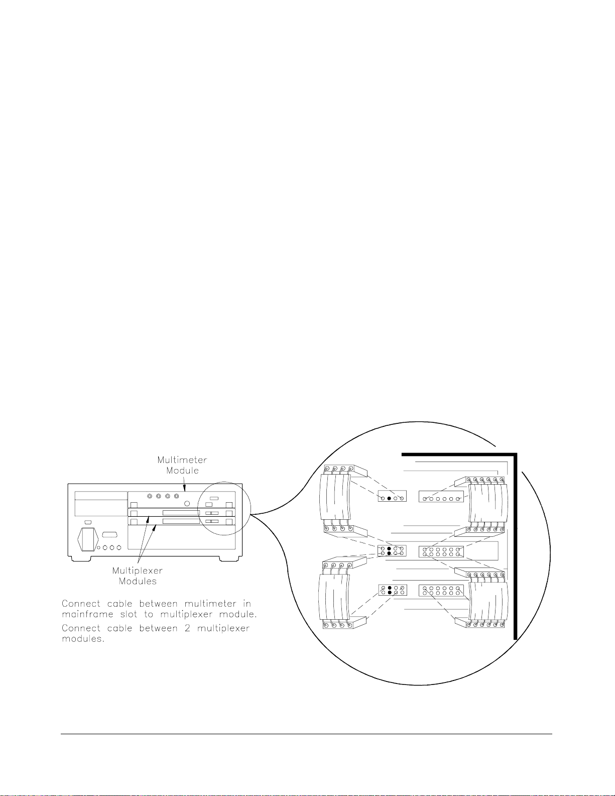
Scanning Voltmeter Configuration with HP E1326B
This example shows an HP E1326B Multimeter and an HP E1351A/
E1353A Multiplexer combined into a single VXIbus instrument, a scanning
voltmeter. The secondary address for the scanning volt meter is 03. Both
the analog bus connector and the digital bus connector are used. Once the
scanning starts, there is no intervention from the mainframe CPU. The scan
list is in RAM on the multiplexer, and the two handshake lines on the digital
bus control the triggering.
The following program illustrates th e proc edures :
10 DIM Rdgs(1:16) !Dimension array to store readi ngs
20 OUTPUT 70903;"*RST;*OPC?" !Clear the multi met e r; O PC?
ensures reset is comple t ed before
program continues
30 OUTPUT 70903;"*CLS"
40 OUTPUT 70903;"CONF:V OLT: DC (@100:115)"
!Configures mul ti met er; also
automatically configures
multiplexer for SCAN:MODE,
SCAN:PORT and TRIG:SOUR
50 OUTPUT 70903:"INIT" !Close first channel, start scan
60 OUTPUT 70903;"FETC?" !Retri ev e rea din gs from mai nf rame
70 ENTER 70903;Rdgs(*)
80 PRINT Rdgs(*)
90 END
Figure 3-6. Connect in g the Anal o g Bus and Digital Bus Cable s
42 Using the HP E1351A/53A FET Multiplexer Modules Chapter 3
Page 43

Measuring Temperature Using Thermocouples
(HP E1353A Module only)
The thermocouple terminal module automatically configures the HP
E1353A FET Multiplexer Module for thermocoup le r eadings. The
multimet er measu r es th e resistance of a th ermistor on the term inal module
to provide a reference t emperat ure. This re feren ce temperatu re is used to
compensate for the change in temperature between the thermocouple
(desired measurement) and the terminal temperature (see “Comments” later
in this section).
Setup for
Measuring
Thermocouple
Temperature using
an Extern al
Multimeter
Figure 3-7 shows how to set up channel 01 of a single module switchbox to
measure temperature using a thermocouple and an external multimeter.
Figure 3-7. Temperature Measuremen t Using a Thermocoup le
Chapter 3 Using the HP E1351A/53A FET Multiplexer Modules 43
Page 44

Comments Measuring Temperature with the HP El326B/El411B Multimeters. The
HP E1326B/E1411B Multimeters can directly measure channels of single or
multiple multiplexer modules. The multimeter automatically calculates the
correct temperature for the specific thermistor or thermocouple type used. For
more information, se e the HP E1326B/E1411B Multimeter User’s Manual.
Thermocouple Compensated Measurements. The HP E1353A FET
Multiplexer makes thermocouple compensated measurements. Thermocouple
compensation accounts for the temperature inside the multiplexer terminal
module, which can affect the thermocouple reading. Thermocouple
compensated measurements are made with the HP E1326B/E1411B. More
information on th ese types of measu rements can be found in He wl ett-Packard
Application Note 290, Practical Temperature Measurements.
High-Speed Temperature Measurements. High-speed temperature
measurements can be made by measuring the thermocouple voltage,
compensating the reading, a nd then converting th e voltage to a temperature.
The instrument configuration us ed f or thes e types of measurements may
include an E1326B/E1411B Multimeter and a FET multiplexer switchbox,
or an external voltmeter used with the FET switchbox. The procedure for
these types of measurements is:
1. Measure t he r esistance of the thermistor (channel 93) on the
multiple xer terminal mod ule (
2. Measure the thermocouple voltage on the multiplexer channel.
3. Convert the thermistor resistance to a temperatur e using the
follo wing equation:
t = 1.0 / ( A + B
t = t - 273.15 convert K elvin to Centigrade
where:
A = 0.00128463
B = 0.00023625
C = 9.2697E-8
lnr = natural log o f t he measured th ermistor r e sistance
A, B, and C are the curve-fitting constants for the multiplexer’s
5K thermistor.
4. Convert the thermistor t emp eratur e (step 3) to a voltage using the
reference table for the type of thermocouple used.
lnr + C * (lnr)3)calculate temperature
*
CLOSe(@cc93)).
5. Subtract the voltage (step 4) from the thermocouple voltage
measured in step 2. Convert the difference between the voltages to a
temperature, again using the reference table for the type of
thermocouple used.
6. Add the temperature (step 5) to the thermistor temperature computed
in step 3 to obtain t he result of t he the rmocouple measur em e nt.
44 Using the HP E1351A/53A FET Multiplexer Modules Chapter 3
Page 45

Understanding the HP E1351A/53A FET
Multiplexer Modules
Using This Chapter
This chapter explains techniques to scan the channels of 16-Channel FET
and 16-Channel The r mocouple FET Mult ip le xer Modules. This chapt er
contains the following sections:
• Commands for Scanning Switchbox Channels . . . . . . . . . . . Page 45
• Using S c ann in g Tri gger S ources. . . . . . . . . . . . . . . . . . . . . . Page 45
• Using the Scan Complete Bi t. . . . . . . . . . . . . . . . . . . . . . . . . Pag e 52
Commands for Scanning Switchbox Channels
Scanning multiplexer channels consists of closing a set of channels, one at a
time. The multiplexer has single, multiple, or continuous scanning modes.
See Figure 4-1 for the dif ferent commands us ed in scanning.
Chapter 4
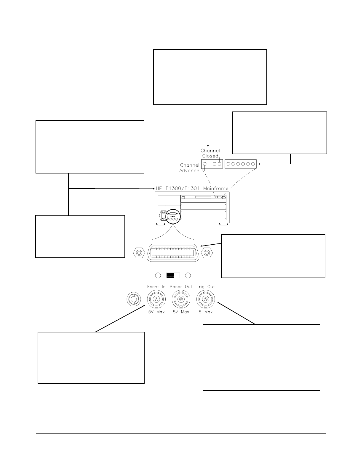
Using Scanning Trigger Sources
The TRIGger:S OURce command specifies the source to advance the
channel list. Figure 4-2 shows the different trigger sources.
uses the digital bus handshake lines. You can use th e TRIG[:IMM]
DBUS
command t o imme diately advance the channel list whil e in the TRIG:SOUR
or TRIG:S OUR HO LD mode. (Note that TRIG:SOUR IMM is not the
BUS
TRIG[:IMM].) To enable the HP E1300/E130 1 Mainframe "Trig
OUTP ON c omma nd. The "Event In" mainfra me trigger
TRIG:SO U R E XT command. "Tri g Out" and
• HP-IB select code of 7
• HP-IB primary address of 09 for the HP E1300/E1301 Mainframe
Scanning with
External
Instruments
same as
Out" port, use the
source is reserved with the
"Event In" are mainframe resourc es, and can only be allocated to o ne
instrume nt at a time .
The examples in this c hapt er s how diff erent ways t o scan channels of a
switchb ox in an HP E1 300/E1301 Mainframe. The operation is similar to
other HP VXIbus mainframes with HP command modules that have "Trig
Out" and "Event In" ports. The computer used in the examples is an HP
Series 200/300 used with HP B ASIC as t he program language. The
computer interfaces with the mainframe over HP-IB. Assumed is an:
TRIG:SOUR
• HP-IB primary address of 22 for the HP 3457A Multimeter
• HP-IB secondary address of 14 for the multiplexer module
Chapter 4 Understanding the HP E1351A/53A FET Multiplexer Modules 45
Page 46
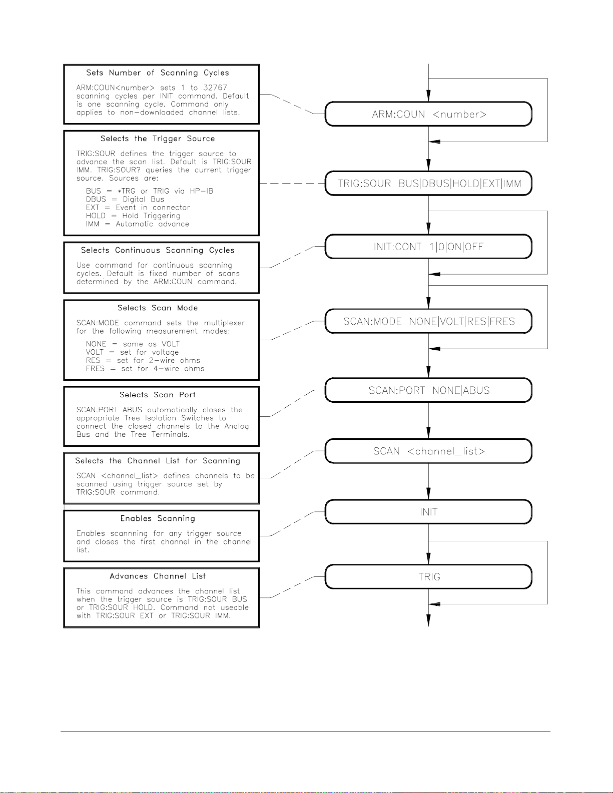
Figure 4-1. Scanning Commands
46 Understanding the HP E1351A/53A FET Multiplexer Modules Chapter 4
Page 47
Imme di ate Tri ggering (TRI G :SO UR I MM)
Sets immediate internal triggering. The scan
list is automatica lly advanc ed t hrough t h e
scan list. Due to the high speed of the FET
multiple xer, this mode should b e used with
consid erat ion f or th e capabi li ty of th e
multimeter. This is the default trigger mode.
Trigger Hold (TRIG:SO UR HO LD)
Handshake Tr igger ing (T RIG:SO UR BUS)
Uses digital bus on faceplate of multiplexer
module. Channel Advance and Chan n el
Closed contin u ousl y handsh a k e with
Voltmeter Ready and Voltmet er Com plet e unti l
scanning list has completed specified numb er
of cycles.
Advancing Scan (TRIG[:IMM]
This command advan c es the scan lis t
when in TRIG:SOUR HOL D or
TRIG:SOUR BUS. Advanc es the scan
list one channel per command.
Prevents execution of triggers until
trigger source is chang ed. Can us e
TRIG[:IMM] command to trigg er a
switchbox set to TRIG:SOUR HOLD.
External Trig g eri ng (TRIG:SOUR EXT)
Trigger source is a user supplied input to
the Event In BNC. Use a +5V
negative-going pulse to trigger.
TRIG:SOUR EXT r eserves th e Event In
resource so it i s not available f or a ny other
ins trumen t in the mainframe.
Bus Triggering (TRIG:SOUR BUS)
Defines Trigger sou rce as *TRG or HP-I B
GET command exec uted over the HP-IB.
The scan list is advan ced one channel for
each *TRG or GET command received.
En a blin g Trig Out Po r t (OUTP ON)
Generates a +5V negativ e-going pulse each
time a channel advances. OUTP ON reserves
the Trig O ut Port so it is no t av ai labl e for any
other instrument in the mainframe.
As an alternative to OUTP ON, the Channel
Closed on th e digital bus also puls es for each
channel clos ure.
Figure 4-2. Trigger Sources
Chapter 4 Understanding the HP E1351A/53A FET Multiplexer Modules 47
Page 48

Example: Scanning
with External
Instruments
This example uses the mainframe "Trig Out" port to synchronize the
multiplexers to an HP 3457A Digital Mu lt imeter. See the following figure
for typical c onnect ions. For this example, use the trigger output pulse of the
mainframe "Trig Out" port to trigger the multimeter from its "External
Trigger" port.
The sequence of operation is:
INIT (line 70) closes channel number 100.
1.
2. The channel closure causes a trigger output from the "Trig Out" port.
3. The trigger causes the multimeter to make a measurement.
4. Measurement result is sent to the computer ( lines 80 to 100).
TRIGGER command (line 110) a dva nces the channel list to the next
5.
channel.
6. Steps 2-5 are repeated for channels 101 through 115.
10 OUTPUT 722;"TRI G E XT;DCV" !Sets multimeter to external trigger
and to measure dc volts
20 OUTPUT 70914;"O UT P ON" !Enables "Trig Out" port
30 OUTPUT 70914;"TRI G:SO UR BUS" !Sets switchbox to receive bu s
40 OUTPUT 70914;"SCAN:MO DE VOLT "! Sets switchbox to measure
50 OUTPUT 70914;"SCAN:PORT ABUS" !Closes the tree isolation switches
60 OUTPUT 70914;"SCAN (@100:115)"!Selec ts the channel list for
70 OUTPUT 70914;"INIT" !Starts scanning cycle
80 FOR I = 1 TO 16 !Start count loop
90 ENTER 722;A !Ent er reading into vari abl e A
100 PRINT A !Print reading in variable A
110 TRIGGER 70914 !Trigger the s witchbox to advance
120 NEXT I !Inc r ement count
130 END
trigger s
voltage
scanning
the channel list
48 Understanding the HP E1351A/53A FET Multiplexer Modules Chapter 4
Page 49

Example: Scanning
Using "Trig Out" and
"Event In" Ports
This example uses the mainframe "Trig Out" and "Event In" ports to
synchronize the multiplexers to an HP 3457A Digital Multimeter. See the
follo wing figure for typical connections.
For this example, use the trigger output pulse of the mainframe’s "Trig Out"
port to trigger the multimeter from its "External Trigger" port. Note that the
pulse output from the multimeter’s "Voltmeter Complete" port triggers th e
switchbox to advance the channel list. Use the multimeter’s rea ding st o ra ge
capability to store readings.
The sequence of operation is:
INIT (line 50) closes channel number 100.
1.
2. The channel closure causes a trigger output from the "Trig Out" port.
3. The trigger causes the multimeter to make a measurement.
4. Measurement result is stored into multimeter memory.
5. Trigger is out put fr om multimeter’s " Voltme ter Complete" port.
6. Trigger to "Event In" port advances the channel list to the next channel.
7. Steps 2-6 are repeated for channels 101 through 115.
10 OUTPUT 722;"T RI G E XT: DCV:M EM FIFO"
!Sets multimeter to external trigger
to measu re dc volts and store
readings
20 OUTPUT 70914;"O UT P ON" !Enables "Trig Out" port
30 OUTPUT 70914;"TRI G:SO UR EXT " !Sets switchbox to recei ve ex te rnal
trigger s
40 OUTPUT 70914;"SCAN (@100:115)"!Selec ts the channel list (c hannels
100 to 115)
50 OUTPUT 70914;"INIT" !Start s scan nin g cyc le
60 END
Chapter 4 Understanding the HP E1351A/53A FET Multiplexer Modules 49
Page 50
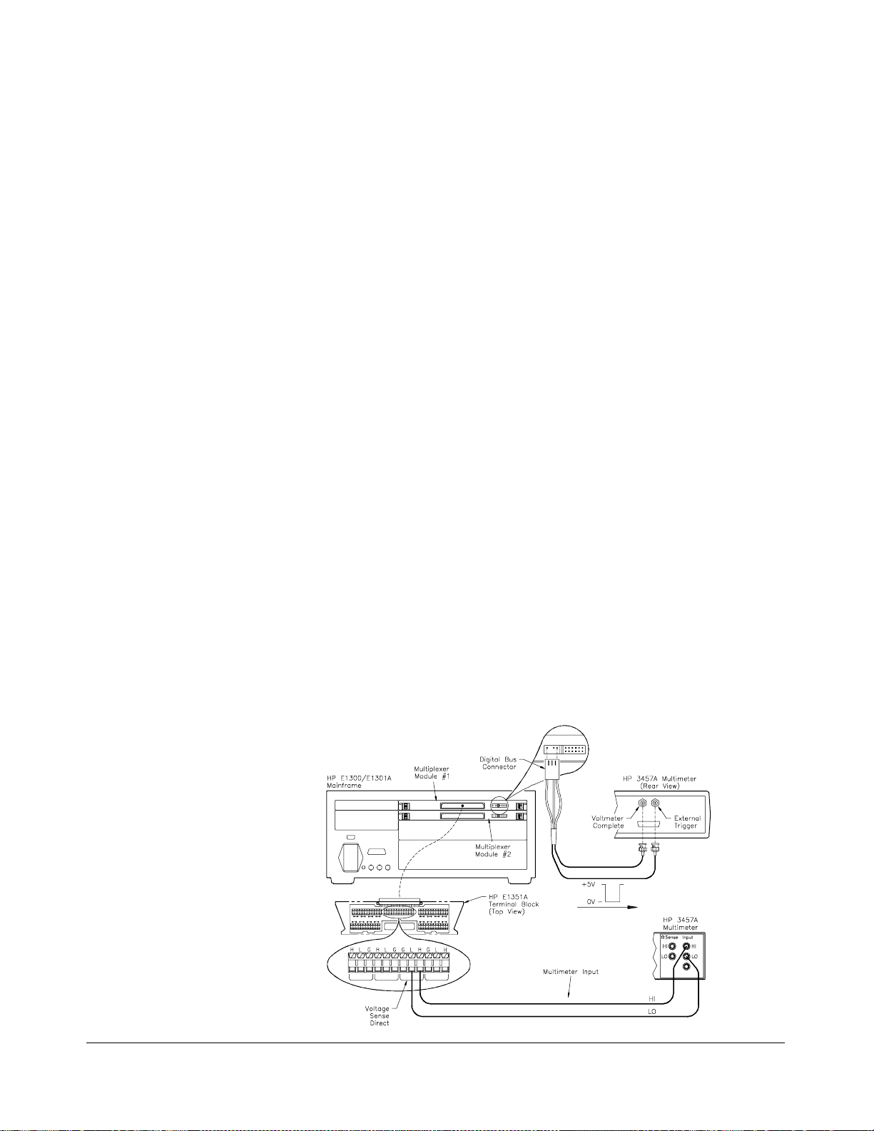
Example: Scanning
Using Stand-Alone
Multimeter and Digital
Bus Triggering
This example is similar to the previous one except that the multimeter’s
"External Trigger" and "Voltmeter Complete" ports are connected to the
"Channel Closed" and "Channel Advance" on th e FET Multiplexer digital bus.
See Chapter 1 for information on making custo m digital bus cab les. Once the
scanning procedure has been initiated (
by the handshake lines. The
INIT co mmand closes the first channel, and when
INIT), the channel closure is advanced
the channel is closed, the " Channel Closed" pulses. This is connected to th e
"External Trigger" on the multimeter, which triggers a reading. When the
reading is complete, the "Voltmeter Complete" triggers, which pulses the
"Channel Advance". This procedure continues until the end of the scan list.
The sequence of operation is:
TRIG:SOUR DBUS selects digital bus triggering .
1.
INIT (line 50) closes channel number 100.
2.
3. The channel closure causes a trigger output from t he "Chann el
Closed" port.
4. The trigger causes the multimeter to make a measurement.
5. Measurement result is stored into multimeter memory.
6. Trigger is out put fr om multimeter’s " Voltme ter Complete" port.
7. Trigger to "Advance Channel" port advances the channel list to the
next channel.
8. Steps 3-7 are repeated for channels 101 through 115.
10 OUTPUT 722;"T RI G E XT; DCV;M EM FIFO"
!Sets multimeter to external trigger
to measu re dc volts and store
readings
20 OUTPUT 70914;"SCAN:PORT ABUS" !R out es c h an ne ls to analog bus
connecto r and A tre e termi nal
30 OUTPUT 70914;"TRIG:SO UR DB US"!S ets switchbox to rec eiv e exte rnal
trigger s
40 OUTPUT 70914;"SCAN (@100:115)"!Selec ts the channel list (c hannels
100 to 115)
50 OUTPUT 70914;"INIT" !Starts scanning cycle
60 END
50 Understanding the HP E1351A/53A FET Multiplexer Modules Chapter 4
Page 51

Example: Scanning
Using Scanning
Voltmeter
Configuration and
Digital Bus Triggering
In this example the HP E1326B Mult imeter is combined with a FET
multiplexer to form a scannin g voltmeter VXIbus instrument. The
multime t er is addr ess 24, and th e mu ltip lex er is addre ss 25, s o th e
instrument secondary address is 03. The analog bus connector and the
digital bus connector are connected between the modules. The
TRIG:SOURce is set for DBUS. This configuration provides the fastest
speed. Consult the HP E1326B/E1411B Multimeter User’s Manual for
further i nformat ion o n multimeter s et tings. Note that the
ARM:COUNt
command does not apply to downloaded scan lists.
The sequence of operation is:
1. The multimeter automatically configures the multiplexer for
SCAN:MODE, SCAN:PORT and TRIGger:SOURce DBUS.
INIT closes first channel.
2.
3. The channel closure causes a trigger output from t he "Chann el
Closed" port.
4. The trigger causes the multimeter to make a measurement.
5. Measurement result is stored into multimeter memory.
6. Trigger is out put fr om multimeter’s " Voltme ter Complete" port.
7. Trigger to "Advance Channel" port advances the channel list to the
next channel.
8. Steps 3-7 are repeated for channels 101 through 115.
10 DIM Rdgs(1:16) !Dimension array for readings
20 OUTPUT 70903;"*RST" !Reset scanning voltmeter
30 OUTPUT 70903;"CONF:V OLT DC (@ 100: 115)"
!Sets multimeter to measure dc volts
40 OUTPUT 70903;"INIT" !Starts scanning cycle
50 OUTPUT 70903;"FETC?" !Get the readings
60 ENTER 70903;Rdgs(*) !Place values in array
70 PRINT Rdgs(*) !Print values
80 END
Chapter 4 Understanding the HP E1351A/53A FET Multiplexer Modules 51
Page 52

Using the Scan Complete Bit
You can use the Scan Complete Bit (bit 8) in the SCPI Operation Status
Register to determine when a scanning cycle completes (no other bits in the
register apply to the switchbox). Bit 8 has a decimal value of 256 and you
can read it direc t ly with t he
STATus:OPERation[:EVENt]? command in Chapter 5 for an example).
Note that this is not the same register as the multiplexer Status/Control
Register.
STAT:OPER? command (refer to the
Example: Scan
Complete Monitor
When enabled by the
STAT:OPER:E NAB 2 5 6 comma nd, the Scan Complete
Bit will b e reported as bit 7 of the Status Register. Us e the HP -IB Serial
Poll or the IEEE 488.2 Common Command
Register. When bit 7 of the status Register is enabled by the
*STB? to read the Status
*SRE 128
Common Co mman d to assert an HP-IB Service Request (SRQ), you can
interrupt the controller when the Scan Complete Bit is set, after a scanning
cycle completes. This allows the controller to do other operations while the
scannin g cycle is in progress.
The following example monitors bit 7 in the Status Register to determine
when the scanning cycle completes. The computer used in the example is
an HP Series 200/300 us ed wit h HP BASIC as the program language. The
computer interfaces with the mainframe over HP-IB. The HP-IB select
code is 7, the HP-IB primary address is 09, and the HP-IB secondary
address is 14.
10 OUTPUT 70914;"*CLS" !Clear all switchbox status
structure
20 OUTPUT 70914;"STAT:OPER:ENAB 256"
!Enable Scan Comp le te Bit to set
bit 7 in Stat us R eg ist e r
30 OUTPUT 70914;"*SRE 128" !Enable bit 7 of Status Register to
40 OUTPUT 70914;"TRI G:SO UR EXT " !Set to external trigger mode
50 OUTPUT 70914;"SCAN (@100:115)"!Selec t cha nne ls t o be scan ne d
60 OUTPUT 70914;"INIT" !Start scanning cycle
70 WHILE NOT BIT (SPOLL(70914),7) !Waiting for scan complete
80 PRINT "DO OTHER OPE RATION HERE"
90 END WHILE
100 PRINT "INTERRUPT GENERATED" !Program goes to this line after
110 END
assert SRQ
!Enter program line s for compu te r
to do other operations
interrupt is generat ed by a
complete d scanni ng c yc le
52 Understanding the HP E1351A/53A FET Multiplexer Modules Chapter 4
Page 53

HP E1351A/53A 16-Channel FET
Multiplexer Command Reference
Using This Chapter
This chapter describes Standard Commands for Programmable Instruments
(SCPI) commands and summarizes IEEE 488.2 Common (*) Commands
applicable to the 16-Channel FET and 16-Channel Thermocouple FET
Multiplexer Modules. This chapter contains the following sections:
Command Types
Chapter 5
• Command Types . . . . . . . . . . . . . . . . . . . . . . . . . . . . . . . . . . Page 53
• SCPI Command Reference . . . . . . . . . . . . . . . . . . . . . . . . . . Page 55
• IEEE 488.2 Common Commands . . . . . . . . . . . . . . . . . . . . . Page 76
• Command Quick Reference. . . . . . . . . . . . . . . . . . . . . . . . . . Page 77
Common
Command Format
SCPI Command
Format
Comman ds are s eparat ed i nto two types: IEEE 488.2 Common C ommands
and SCPI Co mmands.
The IEEE 488.2 standard defines the Co mmon Co mmands that perform
functions lik e reset, self-t est , status byt e query, etc. Common Comman ds
are three or four characters in length, always begin with the asterisk
character (*), and may include one or mor e pa r a me ters. The comm a nd
keyword is separated from the first parameter by a space character. Some
examples of Common Commands are shown below:
*RST *ESR 32 *STB?
The S CPI commands perf`orm functions like closing switches, making
measurements, q u erying instrument states or retrieving data. A subsystem
command structure is a hierarchica l structure that usually consists of a
top-lev el (or root) command, one or more l ower level commands, and their
parameters. The following example shows part of a typical subsystem:
[ROUTe:]
CLOSe <
SCAN <
channel_list>
channel_list>
:MODE VOLT
[ROUTe:] is the root command, CLOSe and SCAN are second-level
commands with <channel_list> as a parameter, and
command with the parameter
Chapter 5 HP E1351A/53A 16-Channel FET Multiplexer Command Reference 53
VOLT.
MODE is a third-level
Page 54

Command Separator A colon (:) al ways separates one command fr om the next lower level
command as shown below:
ROUTe:SCAN: MODE VO LT
Colons separate the root command from the second-level command
ROUTe:SCAN) and the second-level from the third-level (SCAN:MODE
(
). The parameters of a c omma nd a re separated from the command by
VOLT
a blank space.
Abbreviated
Commands
The command syntax shows most commands as a mixture of upper and
lower cas e letters. The upp er case letters indicat e the ab br eviated spelli ng
for the command. For shorter program lines, send the abbre v ia ted form.
For better progra m r e adability, you may send the entire command. The
instrument will accept either the abbreviated form or the entire command.
For example, if the c ommand s yntax shows
MEASURE are both acceptable forms. Other forms of MEASure, such as
MEASU or MEASU R w ill ge ne r a te an error. You may use upper or lower
case letters. The refore ,
MEASURE, measure, and MeAsUrE are all
MEASure, then MEAS and
acceptable.
Comman d keywords can be entered in th eir full form , as shown above, or
can be entered in their short form. In this manual, the entry required in
short form commands is alwa ys capita lized. The short form is generally
used for examples in this manual.
Implied Commands I mplied co mmands are those which appear in square brack ets ([ ]) in the
command syntax. (Note that the brackets are not part of the command and
are not sent to the instrument.) Suppose you send a second level command
but do not send the preceding implied command. In this case, the
instru ment assu mes you intend to us e the implied c ommand and it res pon ds
as if you had sent it. Examine this ex c erpt from the
shown below:
[ROUTe:] subsystem
[ROUTe:]
SCAN <
channel_list>
:MODE <
:MODE?
:PORT <
mode>
port>
Both the root command [ ROUTe:] is an implied command. To set the
instru ment’s scanning list, you can s end either of t he f ollowing command
statements:
ROUTe:SCAN (@100:115) or SCAN (@100:115)
Note You must include a space between the keywords and any parameters.
54 HP E1351A/53A 16-Channel FET Multiplexer Command Reference Chapter 5
Page 55

Parameters Parameter Types. The following table contains explanations and examples
of parameter t ypes you mi ght s ee lat er in this chapt er.
Parameter T ype Explanatio ns and Ex am pl es
Numeric Accepts all commonly used decimal representations of
numbers including opt ional signs, decimal poi nts, a nd
scientific notation.
123, 123E2, -123, -1.23E2, .123, 1.23E-2, 1.23000E-01.
Special cases include MIN, MAX, and DEF. MIN selects
minimum value avai labl e, MA X selects m axi mum valu e
available, and DEF select s default or reset value.
Boolean Represents a single binary condition that is either true or false.
1 or ON; 0 or OF F.
Discrete Selects from a finite num ber of val u es. Th e se paramet e r s
use mnemonics to represent each valid setting.
An example is the TRIG ger:S OURc e <
source can be BUS, DBUS, EXT, HOLD, or IM M.
where
source> command
Optional Parameters. Parameters shown within square brackets ([ ]) are
optional parameters. (Note that the brackets are not part of the command
and are not sent to the instr ument.) If you do not specify a value for an
optional parameter, the instrument chooses a default value. For example,
consider the
com man d wi thou t s pec ifyi ng a p arameter, th e present
returned. If you send the
minimum count available. If you send the
ARM:COUNt? [<MIN | MAX>] command. If you send the
ARM:COUNt valu e is
MIN parameter, the command returns the
MAX parameter, the command
returns the maximum count available. Be sure to place a space between the
command and t he par ameter.
Linking Commands Linking IEEE 488.2 Common Commands with SCPI Commands.
Use a semic olon b etw een the commands. For e xa mple:
*RST;OUTP ON or TRIG:SOUR BUS;*T RG
Linking Mul tip le S CPI C ommands . Use both a s em icolon and a colon
between the commands. For example:
ARM:COUN 1;:TRI G:SO UR EXT
SCPI Command Reference
This section describes the Standard Commands for Programmable
Instru ments (SCPI) commands for the multip lex er modu les. Commands are
listed alphabetically by subsyst em and also within each sub system.
Chapter 5 HP E1351A/53A 16-Channel FET Multiplexer Command Reference 55
Page 56

ABORt
Subsystem Syntax ABORt
The ABORt su b system stops a scan in progress when the scan is enabled via
the interface, and the trigger modes are
TRIGger:SOURce HOLD.
TRIGger:SOURce BUS or
Comments • ABORt Operation. Resets the trigger system and places triggers in
idle. The scan is st opped wit hout r es etting the scan conditions. The
scan conditions stay in the curr ent c on figuration.
• Stopping Scans Enabled from Interface. When a scan is enabled
from the interface, use an interface
E1301 front panel "Reset Instr" or "Clear Instr" key to stop the scan.
When the scan is enabled from the interface and the trigger source is
TRIGger:SOURce BUS or TRIGger:SOURce HOLD, u se ABORt or
the HP E1301 front panel "Reset Instr "or "Clear Instr "keys t o stop
the scan.
CLEAR command or the HP
• Stopping Scans Enabled from Front Panel. When a scan is
enabled from the HP E1301 front panel execute
interface or use the front panel "Reset Instr " or "Clear Instr" keys to
stop the scan.
*RST over the
• Related Commands. ARM, INITiate:CONTinuous, [ROUTe:]SCAN,
TRIGger
Example Stopping a Scan with ABORt
TRIG:SOUR BUS Bus is trigger source .
INIT:CONT ON Set contin uous sc ann ing .
SCAN (@100:115) Sets channel list.
INIT Starts scann ing cycle .
.
.
.
ABOR Aborts scan in progress.
56 HP E1351A/53A 16-Channel FET Multiplexer Command Reference Chapter 5
Page 57

ARM
Subsystem Syntax ARM
The ARM subsystem selects the numb er of scanning cycles (1 - 32767) for
INIT command. This command does not app ly t o downloaded scan
each
lists. For downloaded scan lists, use
:COUNt <
:COUNt? [MIN | MAX]
number> MIN | MAX
INIT:CONT ON for multiple sca ns.
:COUNt ARM:COUNt <number> MIN | MAX allows scanning cycles to occur a
multiple of ti mes (1 to 32767) with on e
INITiate:CONTinuous OFF | 0 is set. MIN sets 1 scanning cycle and MAX
sets 32,767 sca nning cycles.
Parameters
Parameter Name Parameter Type Range of Values
INITia te command and when
number
Numeric 1 - 32767 | MIN | MAX
Comments • Number of Scans: Use only numeric valu es between 1 to 32767 f or
the number of scanning cycles (default is 1).
• Related Commands: ABORt, INITiate[:IMMediate]
• *RST Co ndition: ARM:COUNt 1
Example Settin g Ten Scann in g Cycles
ARM:COUN 10 Set 10 scanning cycles.
SCAN (@100:115) Sets cha n ne l li st.
INIT Starts scann ing cycle .
:COUNt? ARM:COUNt? [MIN | MAX] returns th e current numb er of scannin g cycles
ARM:COUNt. ARM:COUN? MIN returns 1 and ARM:COUN? MAX
set by
returns 32767.
Parameters
Parameter Name Parameter Type Range of Values
MIN | MAX Numeric MIN = 1, MAX = 32767
Comme nt s • Related Commands: INITiate[:IMMediate]
Example Query Number of Scanning Cycles
ARM:COUN 10 Sets 10 scanning cycles.
ARM COUN? Query number of sc ann ing cycle s;
returned value is 10.
Chapter 5 HP E1351A/53A 16-Channel FET Multiplexer Command Reference 57
Page 58

DISPlay
Subsystem Syntax DISPlay
:MONitor:CARD DISPlay:MONitor:CARD <number | AUTO> selects the module in a
Parameters
The DISPlay subsystem monit ors t he channel state of a selected module (or
card). This command can only be used when the FET multiplexer module
is used in a switchbox configuration. It operates with mainframes that have
a display, such as the HP 75000 Series B Mainframe (HP Model Number
E1301). It also operates with terminals connected to the serial interface port.
:MONitor
:CARD <
[:STAT e] <
switchbox to be monitored.
Parameter Name Parameter Type Range of Values
number | AUTO>
mode>
number | AUTO
Numeric 1 - 99
Comments • Selecting a Specific Module to be Monitored: Send the card
number in a switchbox with the
DISPlay:MONitor:CARD command.
• Selecting the Present Module to be Monitored: Use the
DISPlay:MONi tor :CARD AUT O command to select the last module
addressed by a switching command (e.g.,
[ROUTe:]CLOSe ).
• *RST Co ndition: DISPlay:MONitor:CARD AUTO
Example Select Module #2 in a Switchbox for Monitoring
DISP:MON:CARD 2 Se le c ts module #2 in a switchbox.
58 HP E1351A/53A 16-Channel FET Multiplexer Command Reference Chapter 5
Page 59

:MONitor[:STATe ] DISPlay:MONitor[:STATe] <mode> turns the monitor mode on or off.
Parameters
Parameter Name Parameter Type Range of Values
mode
Boolean 0 | 1 | ON | OFF
Comme nt s • Moni toring Switchbo x Chann els : DIS Play: MO Ni tor [:ST AT e] ON
or DISPlay:MONitor[:STATe] 1 turns the monitor mode o n to show
the channel state of the selected module.
OFF
or DISPlay:M ONitor[:STATe] 0 turns the monitor mo de o ff.
DISPlay:MO Ni tor[:STATe]
• Selecting the Module to be Monitored: Use the DISPlay
MONitor:CARD <
number> | AUTO command to select the module.
• Monitor Mode on an HP 1301 Mainframe Display: The
following three examples show the types of display you will get:
Chan: _ No channe ls c lose d on this card.
Chan: 12 Channel 12 closed.
Chan: 9,1 4-wire ohms set-u p with volt age on
channel 9.
• *RST Co ndition: DI SPlay: MO Ni t or[: ST AT e] OFF | 0
Example Enabling the Monitor Mode
DISP:MON:CARD 2 Se le c ts module #2 in a switchbox.
DISP:MON 1 Turns the monitor mode on.
Chapter 5 HP E1351A/53A 16-Channel FET Multiplexer Command Reference 59
Page 60

INITiate
Subsystem Syntax INITiate
:CONTinuous INITiate:CONTinuous <mode> enables or disables continuous scanning
Parameters
The INITiate subsystem selects continuous sca nning cycles and starts the
scannin g cycle.
:CONTinuous <
:CONTinuous?
[:IMMediat e]
cycles for the switchbox or scanning voltmeter.
Parameter Name Parameter Type Range of Values
mode>
mode
Boolean 0 | 1 | ON | OFF
Comme nt s • Continuous Scanning Operation: Continuous scanning is enabled
with the
command. Sending the INITiat e[:IMMediat e] command closes the
first channel in the channel list. Each trigger from a trigger source
specified by the
through the channel list. A trigger at th e end of the channel list
closes the first channel in the chann el list and the scan cycle repeats.
Continuous scan ning can be stoppe d by the
non-downloaded scans, and by a system reset or a power off for
downloaded sca n list s.
INITiate:CONTinuous ON or INITiate:CONTinuous 1
TRIGger:SOURce command advances the scan
ABORt command for
• Scanning a Set Number of Cycles: The INITiate:CONTinuous OFF
or INITiate:CONTinuous 0 command goes through the scan list the
number of times specified by the
INITiate[:IMMediate] command closes the first channel in the
the
channel list. Each trigger from a trigger source selected by the
TRIGger:SOURce command advances the scan through the channel
list. A trigger at the end of the channel lis t op ens the last channel in
the channel list, and if the number of cycles has not reached the
ARM:COUNt parameter, returns to the beginning of the scan list and
closes the first channel. When the nu mber of cycles equals the
ARM:COUNt parameter, the scanning cycle stops. Note that
ARM:COUNt does not apply to downloaded scan lists.
ARM:COUNt command. Sending
• Stopping Continuous Scans: Continuous scanning can be stopped
ABORt command for non-downloaded scans, and by a system
by the
reset or a power off for downloaded scan lists.
• Related Commands: ABORt, ARM:COUNt, *RST, TRIGger ,
TRIGger:SOURce
• *RST Co ndit ion: INITiate:CONTinuous OFF
60 HP E1351A/53A 16-Channel FET Multiplexer Command Reference Chapter 5
Page 61

Example Enabling Continuous Scans
INIT:CONT ON Enables continuous scanning.
SCAN (@100:115) Sets cha n ne l li st.
INIT Starts scann ing cycle .
:CONTinuous? INITiate:CONT i nu o u s? queries the scanning state. With continuous
scannin g enabled, the c omma nd r e turns 1 (ON). With continuous scanning
disabled, the command returns 0 (OFF).
Example Query Co nt in uous Scanning Sta te
INIT:CONT ON Enables continuous scanning.
INIT:CONT? Query continuous scanning state.
[:IMMediate] INITiate[:IMMediate] star ts t he sca nning cycle and closes the f irst c hannel
in the channel list. Successive triggers from the source specified by the
TRIGger:SOURce command advances the scan through the channel list.
Comments • Starting the Scanning Cycle: The INITiate[:IMMediate] command
starts scanni ng b y closing the first channel in the cha nnel lis t. Each
trigger rec eived adva nces the scan to the next c hannel in the channel
list. An invalid channel list generates an error (see the
[ROUTe:]SCAN c ommand).
• Stopping Scanning Cycles: See the ABORt command.
Example Enabling a Single Scan
SCAN (@100:115) Sets cha n ne l li st.
INIT Starts scann ing cycle .
Chapter 5 HP E1351A/53A 16-Channel FET Multiplexer Command Reference 61
Page 62

OUTPut
Subsystem Syntax OUTPut
The OUTPut subsystem enab les or disables the "Trig Out" port of the HP
E1300/E1301 Mainframe.
[:STAT e] <
[:STATe]?
state>
[:STATe] OUTPut [:STAT e] <state> enables/disables the "Trig Out" port on the rear
OUTPut [: ST AT e] ON | 1 enables
Parameters
panel of the HP E1300/E1301 Mainframe.
the port and
Parameter Name Parameter Type Range of Values
OUTPut[:STATe] OFF | 0 disables the po r t.
state
Boolean 0 | 1 | ON | OFF
Comme nt s • Downloaded Scans: The OUTPut subsystem does not work with
downloaded scan lists. The scan list is downloaded automatically if
you use
only).
TRIG:SOUR DBUS or TRIG:SOUR IMM (FET multiplexers
OUTPut works with all other scanning methods.
• Enabling "Trig Out" Port: When enabled, the "Trig Out" port is
pulsed each time a channel is closed during scanning. When
disabled, the "Trig Out" port is not pulsed.
• Output Pulse: The pulse is a +5 V negative-going pulse.
• "Trig Out" Port Reserved by Switchboxes: The "Trig Out"
resource is a system resource, and can only be reserved by one
instrume nt at a time .
• Related Commands: [ROUTe:]SCAN, TRIGger:SOURce
• *RST Co ndition: OUTPut[:STATe] OFF (port disabled)
Example Enablin g "T r ig O ut" Po r t
OUTP ON Enables "Trig Out" port f or pul se
output.
[:STATe]? OUTPut[:ST A Te]? queries the present state of th e "Trig Out" port. The
command returns 1 if the port is enabled, or 0 if disabled.
Example Query "Trig Out" Port State
OUTP ON Enables "Trig Out" port f or pul se
output.
OUTP :STAT? Query port enable state.
62 HP E1351A/53A 16-Channel FET Multiplexer Command Reference Chapter 5
Page 63

[ROUTe:]
Subsystem Syntax [ROUTe:]
The [ROUTe:] subsystem controls switching and scanning operations for the
multiplexer modules in a switchbox.
CLOSe <
CLOSe? <
OPEN <
OPEN? <
SCAN <
SETTling
[:TIME] <
channel_list>
channel_list>
channel_list>
channel list>
channel_list>
:MODE <
:MODE?
:PORT <
:PORT?
mode>
port>
time>, <channel_list>
[:TIME]? [M IN | MAX] <
channel_list>
CLOSe [ROUTe:]CLOSe <channel_list> closes multiplexer channels specified in the
channel list. The chan nel _l ist fo r
circumstances, (@ccnn,ccnn), where cc = card number (00-99) and nn = channel
number (00-1 5). Be fore u sin g the
SCAN:M O D E and SCAN:PORT, as these commands determine what switches
will be closed for a given channel. You can only have one closed channel on a
card at a time. If you want to close a channel on two different cards in the same
VXIbus instrument (for example, 102,208) you can use (@ccn n,ccnn).
CLOSe is in the form (@ccnn), or in special
CLOSe command, you must specify the
Parameters
Parameter Name Parameter Type Range of Values
channel_list
Numeric cc00 - cc15
Comme nt s • Specify SCAN:MODE and SCAN:PORT: Before using the CLOSe
command, specify the SCAN:MOD E and SCAN:PORT.
• Closing Channels: To c lose:
– use [ROUTe:]CLOSe (@ ccnn) for a single channel;
– use [ROUTe:]CLOSe (@ccnn, ccnn) for single channels on
different cards;
– use [ROUTe:]CLOSe (@ccnn, ccnn) f or multiple channels;
– use [ROUTe:]CLOSe (@ccnn: ccnn) for sequential channels;
– use [ROUTe:]CLOSe (@ccnn: ccnn, ccnn: ccnn) for a group of
sequ ential channels;
– or any combination.
Closure order for multiple channels with a single command is
not guaranteed.
• Related Commands: [ROUTe:]OPEN, [ROUTe:]CLOS e?,
[ROUTe:]SCAN:MODE, [ROUTe:]SCAN:PORT
• *RST Co ndition: All multiplexer channels are open.
Chapter 5 HP E1351A/53A 16-Channel FET Multiplexer Command Reference 63
Page 64

Example Closing Mul tiplexer Chann els
Thi s examp le closes c hanne l 0 0 o f a multip lex er mo du le card n umber 1 an d
channel 15 of multiplexer module card number 2 in a single switchbox.
SCAN:MODE VOLT
SCAN:PORT ABUS
CLOS (@100,215) 100 closes channe l 00 of card #1;
215 closes cha nne l 15 of card #2.
CLOSe? [ROUTe:]CLOSe? <channel_list> returns the current state of the
channel(s) qu eried. The channel list is in the form (@ccnn). The command
returns 1 if channels are closed and returns 0 if the channels are open.
Comments • Que r y is Sof tware Readback: The [ROUTe:]CLOSe? command
returns the current software state of the channel specified. It does
not account for relay hardware failures.
Example Que ry M ul tiplexer Channel Closure
CLOS (@100,215) 100 closes channe l 00 of card #1;
215 closes cha nne l 15 of card #2.
CLOS? (@215) Query channel 215.
OPEN [ROUTe:]OPEN <channel_list> opens the multiplexer channels specified
in the channel_list. The channel_list is in the form (@ccnn), (@ccnn,ccnn),
(@ccnn:ccnn) or (@ccnn:ccnn,ccnn:ccnn) where cc = card number (00-99)
and nn = channel nu mber (00-15).
Parameters
Parameter Name Parameter Type Range of Values
channel_list
Comme nt s • Opening Channels: To open:
– use [ROUTe:]OPEN (@ccnn) for a single channel;
– use [ROUTe:]OPEN (@ccnn, ccnn) for multiple channels;
– use [ROUTe:]OPEN (@ccnn: ccnn) for sequential channels;
– use [ROUTe:]OPEN (@ccnn: ccnn, ccnn:ccnn) f or a group of
sequ ential channels;
– or any combination.
Opening order for multiple channels with a single command is not
guaranteed.
• Open Channels: Opening an already open channel has no eff ect.
Numeric cc00 - cc15
• Related Commands: [ROUTe:]CLOSe, [ROUTe:]O PEN?
• *RST Co ndition: All multiplexer channels are open.
64 HP E1351A/53A 16-Channel FET Multiplexer Command Reference Chapter 5
Page 65

Example Opening Multiplexer Channels
This example opens channel 00 of a multiplexer module card number 1 and
channel 15 of multiplexer module card number 2 in a single switchbox.
OPEN (@100,215) 100 opens ch anne l 00 of card #1;
215 opens channe l 15 of card #2.
OPEN? [ROUTe:]O PEN? <channel_list> returns the current state of the channel(s)
queried. The channel list is in the form (@ccnn). The command returns 1
if the channel is open or returns 0 if the channel is closed.
Comments • Que r y is Sof tware Readback: The [ROUTe:]OPEN? command
returns the current software state of the channel(s) sp ecifi ed. It does
not account for relay hardware failures.
Example Que ry M ul tiplexer Channel Open State
OPEN (@100,215) 100 opens ch anne l 00 of card #1;
215 opens channe l 15 of card #2.
OPEN? (@215) Query state of channel 215.
SCAN [ROUTe:]SCAN <channel_list> defines the channels to be scanned. The
channel_list has the form (@ccnn), (@ccnn,ccnn), (@ccnn:ccnn) or
(@ccnn:ccnn,ccnn:ccnn) where cc = card number (00-99) and nn = channel
number (00-15).
Parameters
Parameter Name Parameter Type Range of Values
channel_list
Numeric cc00 - cc15
Comme nt s • Channel List: Valid cha nnel lis ts ar e:
– a single channel, use (@ccnn);
– for multiple channels, use (@ccnn,ccnn);
– sequential channels, us e (@ccnn:ccnn);
– a group of sequential channels, use (@ccnn:ccnn,ccnn:ccnn);
– or any combination.
• Defining the Channel List. When executing [ROUTe:]SCAN, the
channel list is checked for valid card and channel numbers. An error
is generated for an invalid channel list.
• Downloading a Scanni ng List: The channel_list is automatically
downloaded int o RAM on the FET multiple xer modules for
TRIG:SOUR DBUS and TRIG:SOUR IMM trigger modes. The
complete list is downloaded onto each module in an instrument. The
channels are adva nced with no direct i nt ervention by the mainframe
CPU during the scan. If an instrument contains mixed modules
(FET and Relay Mu ltiplexers), the scan lis t w ill not be downloaded.
Chapter 5 HP E1351A/53A 16-Channel FET Multiplexer Command Reference 65
Page 66

• Scanning Operation: With a valid channel list,
INITiate[:IMMediate] starts the scanning cycle and closes the first
channel in t he channel list. Successive triggers from the source
specified by
TRIGger:SOURce advances the scan through the
channel list.
• Stopping Scan: See the ABORt command.
• Related Commands: TRIGger, TRIGger :SOURce
• *RST Co ndition: All multiplexers channels are open.
Example Scanning Using External Instruments
The following example shows how to scan channels us ing the HP E1300A/
E1301A Mainframe via HP-IB and an HP 3457A Digital Multimeter. This
exampl e uses the mainfr ame’s "Trig Out" port to sy nc hronize the
multiplexer module in a switchbox to the multimeter. The trigger pulse
from the port triggers the multimeter for a measurement. See Chapters 2
and 3 for typica l user connect ions to the multiplexer.
The co mputer used in the example is an HP Serie s 200/300 wit h HP BASIC
as the program language. The computer interfaces with the mainframe over
HP-IB. Assumed is an HP-IB select code of 7, an HP-IB primary address of
09 and 22 for the HP E1300A/E1301A Mainframe and HP 3457A
Multimeter, respectively, and an HP-IB secondary address of 14 for the
switchbox.
10 OUTPUT 722;"TRI G E XT;DCV" !Sets multimeter to external trigger
and to measure dc volts
20 OUTPUT 70914;"O UT P ON" !Enables "Trig Out" port
30 OUTPUT 70914;"TRI G:SO UR BUS" !Sets switchbox to receive bu s
trigger s
40 OUTPUT 70914;"SCAN:MO DE VOLT "! Sets switchbox to measure
voltage during scann ing
50 OUTPUT 70914; "SCAN:PO RT ABUS"!Sets switchbox to close the
appropriate tree s witches during
scanning
60 OUTPUT 70914;"SCAN (@100:115)"!Selects the channel list
70 OUTPUT 70914;"INIT" !Starts scanning cycle
80 FOR I = 1 TO 16 !Start count loop
90 ENTER 722;A !Ent er reading into vari abl e A
100 PRINT A !Print reading in variable A
110 TRIGGER 70914 !Trigger the s witchbox to advance
the channel list
120 NEXT I !Inc r ement count
130 END
66 HP E1351A/53A 16-Channel FET Multiplexer Command Reference Chapter 5
Page 67

SCAN:MODE [ROUTe:]SCAN:MODE <mode> sets the multiplexer channels defined by
[ROUTe:] SCAN <ch annel_ list > command for None, Volts, 2-Wire
the
Ohms, or 4-Wire Ohms measurements.
Parameters
Parameter Name Parameter Type Range of Values
mode
Discrete NONE | VOLT | RES | FRES
Comme nts • Order of Command Execution: The [ROUTe:]SCAN:MODE
command must be executed before the [ROUTe:]SCAN < channel_list>
and [ROUTe:]CLOSe <channel_list> comma nds.
• NONE and VOLT Mode Description: When sele cte d , channel list
is set up for volts measurements.
• RES Mode Description: When s elected, chan nel list is set up f or
2-wire o hms meas ur em e nts. The current s ource on I+ and I- is
superimposed on the channel being measured. Appropriate tree
isolation switches are automatically closed.
• FRES Mode Description: When selected, channel list is set up for
4-wire ohms measurements. Specify only the channel on which the
voltage is to be measur e d. The pair e d channel (plus or minus eight
channels away) on the other bank will automatically close. If you
specify both channels (@102, 110), the module will first setup for
FRES reading on 02, then setup for FRES reading o n 10.
• *RST Co ndition: [ROUTe:]SCAN:MODE NONE
Example Selecting the 4-Wire Ohms Mode. This example scans 8 channels for
4-wire ohms resistanc e measurements.
TRIG:S OUR E XT Selects ex te rnal trigger source.
SCAN:MODE FRES Selects the 4-wire ohms scanning
mode.
SCAN (@100:115) Sets cha n ne l li st.
INIT Starts scann ing cycle .
SCAN:MODE? [ROUTe:]SCAN:MODE? returns the current state of the scan mode. The
command retur n s
NONE, VOLT, RES, or FRES mode, respectively.
Example Query Scan Mode
This example selects the 4-wire ohms measurement mode (
queries the measur eme nt stat e. Becaus e 4- wire oh ms mode is select ed, the
query command r et urns
SCAN:MODE FRES Selects the 4-wire ohms scanning
SCAN:MODE? Query the scanning mode.
Chapter 5 HP E1351A/53A 16-Channel FET Multiplexer Command Reference 67
NONE, VOLT, RES, or FRES i f the scan mode is in the
FRES), then
FRES.
mode.
Page 68

SCAN:PORT [ROUTe:]SCAN:PORT <port> enables/disables the tree isolation switches.
SCAN:PORT ABUS closes the appropriate tree switches (for analog bus
connections). The
switches and leaves them open. With
channels can only be measured through the respective bank direct terminals.
Parameters
Parameter Name Parameter Type Range of Values
[ROUTe:]SCAN:PORT NONE c omma nd disables the tree
SCAN:PORT NONE the closed
port
Discrete ABUS | NONE
Comments • Order of Command Execution: The [ROUTe:]SCAN:PORT
command must be executed before the [ROUTe:]SCAN < channel_list>
and [ROUTe:]CLOSe <channel_list> comma nds.
• *RST Co ndition: [ROUTe:]SCAN:PORT NONE
Example Selecting the ABUS Port
TRIG:S OUR E XT Selects ex te rnal trigger source.
SCAN:MODE FRES Selects the 4-wire ohms scanning
mode.
SCAN:PORT ABUS Selects the anal og bus po rt.
SCAN (@100:107) Sets cha n ne l li st.
INIT Starts scann ing cycle .
SCAN:PORT? [ROUTe:]SCAN:PORT? returns the current state of t he ana log bus port.
The co mman d returns
disabled or
ABUS if the control relays are enabled.
Example Query Scan Port
NONE if the analog bus connection control relays are
This example selects the analog bus port, then queries the state. Because
the analog bus port is selected, t he query command returns
SCAN:PORT ABUS Selects the analog bus port.
SCAN:PORT? Query the port selection.
ABUS.
68 HP E1351A/53A 16-Channel FET Multiplexer Command Reference Chapter 5
Page 69

SETTling[:TIME] [ROUTe:]SETTling[:T IM E] <channel_list> sets the delay between receipt
of a channel closing trigger, and the pulse when the FET channel is closed.
You must sp ec if y one and only one channel for each card in the instrument
which has a channel in the channel list, and the
channels on the card. The range is 1 to 32768
Parameters
Parameter Name Parameter Type Range of Values
<time> will then apply to all
µsec.
time
channel_list
Numeric 1E-6 | 32768E-6 | MIN | MAX
Numeric o nly one channel
Comme nt s • Digital Bus Handshaking: This command allows a user-defined
settling time to allow a measurement to be made before the next
channel is closed.
• Related Commands: TRIGger:SOURce DBUS, TRIGger:SOURce
IMMediate
Example Settin g 16 µsec SETTling TI ME
TRIGger:SOUR DBUS Triggering on the digital bus
handshake li ne s
SETTling:TIME 16E-6 Delay = l6µsec
SETTling[:TIME]? [ROUTe:]SE TTling[:TIM E]? [MIN | MAX] <channel_list> returns the
current setting for a specified channel.
and maximum allowable settings.
Parameters
MIN or MAX returns the minimum
Parameter Name Parameter Type Range of Values
MIN | MAX Numeric MIN = 1 µsec, MAX = 32768 µsec
channel_list
Numeric o nly one channel
Comme nt s • Returned value is given in exponential notation.
Example Set and Query the SETTling TIME
SETT:TIME 16E-6 Sets del ay = 16µsec.
SETT:TIME? Returns + 1.600000E-0 05.
Chapter 5 HP E1351A/53A 16-Channel FET Multiplexer Command Reference 69
Page 70

STATus
The STATus subsyst em reports the bit valu es of the Op eration Status
Register. This enables the Status Register to set a bit after a bit is set to 1 by
the Op eration Status Register.
Subsystem Syntax STATus
:OPERation
:ENABle <
[:EVENt]?
:OPERation:ENABle STATus:OPERation :E N ABle <number> enables the Operation Status
Registe r to set a bit in the Status Register. For multiplexer modules, when
bit 8 in the Operation Status Register is set to 1, bit 7 in the Status Register
is set to 1.
Parameters
Parameter Name Parameter Type Range of Values
number>
number
Nume ric 1 - 327 68
Comme nts • Setting Bit 7 of the Status Register: STATus:OPERation:ENABle
256
sets bit 7 of the Status Register to 1 a fter bit 8 of the Op eration
Status Register is set to 1.
• Disabling STATus:OPERation: The STATus:PRESet command
disables the
STATu s:OPERation:ENABle command.
• Related Commands: [ROUTe:]SCAN, *SRE, *STB?, *SPOLL,
STATus:PRESet
Example Enable the Status Register Bit 7
STAT:OPER:ENAB 256 Enabl e s bit 7 of the St at us Re gi ste r.
:OPERation[:EVENt]? STATus: OP ERation [:EVENt ]? returns th e bit value of the Operation
Status Register (only bit 8 is used by the multiplexer modules).
Comments • Setting Bit 8 of the Operation Status Register: Bit 8 (Scan
Complete) is set to 1 after a scanning cycle completes. Bit 8 returns
to 0 after sending the
correct operation set to 0 by
• Returned Data after sending the STATus:O PERat ion [:EV ENt]?
Command: The command returns +256 if bit 8 of the Operation
Status Register is set to 1. The command returns +0 if bit 8 of the
Operat ion Sta tus R egister is set to 0.
STATus:OPERation[:EVENt]? command. For
*CLS before scanning.
• Related Commands: [ROUTe:]SCAN, *SRE, *STB?, *SPOLL
Example Reading the Operation Status Register after a Scanning Cycle
STAT:OPER ? Reads the regist er val ue
read and print the register value +256 shows bit 8 is set to 1; +0
shows bit 8 is set to 0.
70 HP E1351A/53A 16-Channel FET Multiplexer Command Reference Chapter 5
Page 71

SYSTem
Subsystem Syntax SYSTem
:CDEScription? SYSTem:CDEScription? <number> returns the descriptio n of a select ed
Parameters
The SYSTem subsystem returns the error numbers and error messa g es in
the error queue of a switchbox, and returns the types and descriptions of
modules (car ds) in a switchb ox.
:CDEScription?
:CPON
:CTYPe?
:ERRor?
module (card) in a switchbox.
Parameter Name Parameter Type Range of Values
<
number | ALL>
<
number
<
number
>
>
number
Numeric 1 - 99
Comments • 16-Channel FET Multiplexer Module Description: The
SYSTem:CDEScription? <number> command returns:
16 Channel FET Mux
• 16-Channel Thermocouple FET Multiplexer Module Description:
SYSTem:CDEScription? <number > command returns:
The
16 Channel FET Mux with T/C
Example Reading the Description of Card #1 Module
SYST:CDES? 1 Determine the descri ption.
:CPON SYSTem:CPON <number | ALL> opens all channels of a selected modu le,
or all modules (cards) in a switchbox.
Parameters
Parameter Name Parameter Type Range of Values
number
Numeric 1 - 99 | ALL
Comments • Differences between *RST and CPON: SYSTem:CPON only opens
all channels of a sel ected modu l e or all modules in a switch b ox.
*RST opens all channels of all modules in a switchbox and also sets
the trigger modes to the power-on states.
Example Opening All Channels on Card #1
SYST:CPON 1 Opens all chann els on c ard #1.
Chapter 5 HP E1351A/53A 16-Channel FET Multiplexer Command Reference 71
Page 72

:CTYPe? SYSTem:CTYPe? <number> returns the module (card) type of a selected
module in a switchbox.
Parameters
Parameter Name Parameter Type Range of Values
number
Numeric 1 - 99
Comments • 16-Channel FET Multiplexer Module Model Number:
SYSTem:CTYPe? < number> command returns :
The
HEWLETT-PACKARD,E1351A,0,A.03.00
• 16-Channel Thermocouple FET Multiplexer Module Model Number:
SYSTem:CTYPe? < number> command returns :
The
HEWLETT-PACKARD,E1353A,0,A.03.00
Note: T he first number a fter the mod el number is the seri al number
of the module (always 0); the module revision c ode f ollo ws the
serial numb er (f or exa mple, A.03.00).
Example Reading the Model Number of a Card #1 Module
SYST:CTYP? 1 Determine the model number.
:ERRor? SYSTem:ERRor? returns the error numbers and corresponding error
messages in the error queue of a switchbox. See Appendix C for a listing of
the switchbox error numbers and messa ges.
Comme nts • Error Numbers/Messages in the Error Queue: Errors generated
by a switchbox stores an error number and corresponding error
message in the error queue. Each error message can be up to 255
characters long.
• Clearing the Error Queue: An error number/message is removed
from the queue each time the
The errors are cleared first-in, first-out. When the queue is empty,
each following
To c le ar all e rr or numbers/messages in the queue, execute the
command.
SYSTem:ERRor? command returns 0, "No error".
SYSTem:ERRor? command is sent.
*CLS
• Maximum Error Numbers/Messages in the Error Queue: The
queu e hol ds a max imum of 30 error numbers/messa g es for each
switch box. If the queue over flows, t he last error number/message in
the queue is replaced by -350, "Too many errors". The least recent
error numb ers/messages remain in the qu eu e and the most r ecent are
discarded.
Example Reading the Error Queue
SYST:ERR? Query the error queue.
72 HP E1351A/53A 16-Channel FET Multiplexer Command Reference Chapter 5
Page 73

TRIGger
Subsystem Syntax TRIGger
[:IMMediate] TRIGger[:IMMediate] caus es a trigger to occur when the defined trigger
The TRIGger subsyst em c omma nds control the scan triggering operation of
the multip le xer modul es.
[:IMMediat e]
:SOURce BUS | DBUS | EXTernal | HOLD | IMMediate
:SOURce?
source is
TRIGger[:IMM] is not the same as TRI Gger:SOURce IM M.
TRIGger:SOURce HOLD or TRIGger:SOURce BUS. Note that
Comments • Executing the TRIGger[:IMMediate] Command: A channel lis t
must be defi ned wit h the
and an
TRIGger[:I MM ediate] can trigger the switch box.
INITiate[:IMMediate] command must be executed b efore
[ROUTe:]SCAN <channel_list> command
• HOLD or BUS Source Remains: If selected, the TRIGger:SOURce
HOLD
or TRIGger:SO URce BUS c ommands re main in effect after
triggering the switchbox with the
TRIGger[:IMMediate] command.
• Related Commands: INITiate, [ROUTe:]SCAN
Example Advancing Sc an using the TRIGger Command
TRIG:SOUR HO LD Sets t rigg er sou rce to hold .
SCAN (@100:115) Sets cha n ne l li st.
INIT Starts scann ing cycle .
loop statement Start coun t lo op.
TRIG Advance s scan to next chann el.
increment l oo p Increme nt count loop.
Chapter 5 HP E1351A/53A 16-Channel FET Multiplexer Command Reference 73
Page 74

:SOURce TRIGger:SOURce BUS | DBUS | EXTern al | HOLD | IMMediate specifies
the trigg er sourc e to advance the channel list dur ing s canning.
Parameters
Parameter Name Parameter Type Range of Values
BUS Discrete *TRG command
DBUS Discrete Digital Bus
EXTernal Discrete Event In port
HOLD Discrete Hold Triggering
IMMediate Discrete Continuous Triggering
Comme nt s • Enabling the Trigger Source: The TRIGger:SOURce command
only selects t he trigger s ource. The
enables the trigger source.
• Using the TRIG Command: You can use TRIGger[:IMMediate] to
advance the scan when
HOLD
is selected.
TRIGger:SOURce BUS or TRIG ger:S OURce
• Using Digital Bus Trigger: TRIGger:SOURce DBUS selects the
digital bus on the multiplexer as the trigger. Any open collector TTL
trigger source can be wired to the "Channel Advance" lead. A
negative-going pulse triggers t he multiplexer and advances it to the
next channel on the scanning list. After the
the multiple xer asserts "Channel Closed" on th e digital bu s.
INITiate[: IMMediate] command
SETTling:TIME delay,
• Using External Trigger Inputs: With TRIGger:SOURce EXTernal
selected, only one switchbox at a time can use the external trigger
input at the HP E1300A/E1301A Mainframe’s "Event In" port. The
trigger input is assigned to the first switchbox requesting the external
trigger source.
• Assigning External Trigger: A switchbox assigned with
TRIG:S OUR E XT remains assigned to that source until the switchbox
receives a command to change the source. When the source is
changed, t he external trigger sourc e is available to another switchbox
(with a
TRIGger:SOURce EXTernal command). Another switchbox
cannot receive an external trigger source if the source is already
assigned, or an error is generated.
• Using Bus Triggers: To trigger the switchbox with
TRIGger:SOURce BUS selected, use TRIGger[ :I MM edi ate] , the IEEE
488.2 common command
GET).
(
*TRG or the HP-IB Group Execute Trigger
• "Trig Out" Port Shared by Switchboxes: See the OUTPut
command.
• Related Commands: ABORt, [ROUTe:]SCAN, SETTling[:TIME],
TRIGger
• *RST Co ndition: TRIG ger: SOURce IM Medi ate
74 HP E1351A/53A 16-Channel FET Multiplexer Command Reference Chapter 5
Page 75

Example Scanning Using External Triggers
In the following example, the trigger input is applied to the HP
E1300A/E130 1A Main frame’s "E v ent In" port.
TRIG:S OUR E XT Sets trigger source to externa l.
SCAN (@100:115) Sets cha n ne l li st.
INIT Starts scann ing cycle .
trigger externally Advance s scan to next chann el.
Scanning Using Bus Triggers
TRIG:SOUR BUS Sets interface (bu s ) trigge r i ng.
SCAN (@100:115) Sets cha n ne l li st.
INIT Starts scann ing cycle .
*TRG Advanc e s cha nne l list .
:SOURce? TRIGger:SOURce? returns the current trigger source for the switchbox.
Command returns either
sources
BUS, DBUS, EXTernal, HOLD, or IMMedi at e, respecti ve ly.
Example Query Trigger Source
BUS, DBUS, EXT, HOLD, or IMM for trigger
TRIG:S OUR E XT Sets trigger source to externa l.
TRIG:SOUR? Query trigger source; returns
"EXT".
Chapter 5 HP E1351A/53A 16-Channel FET Multiplexer Command Reference 75
Page 76

IEEE 488.2 Common Commands
The following table lists the IEEE 488.2 C ommon (*) Commands that the
16-Channel FET Multiplexer Modules accept. The operation of some of
these commands is described in Chapter 4 of this manual. For more
information on Com mon C om ma nds , re fer t o the H P 75000 Series B
Mainframe User’s Manual (HP Model Number E1300/E1301) or the
ANSI/IEEE Standa rd 488 .2-1 987.
Command Title Description
*IDN? Identification Returns identificati o n st ring of the s witchbox .
*RST Reset
*TST? Self-Test Power-on interrupt returns +110
*OPC
*OPC?
*WAI Wai t to Complete See note below.
*CLS Clear status Clears all status registers (see STATus:OPERation[:EVENt]?).
*ESE
*ESE?
*ESR? Event status register query See note below.
*SRE
*SRE?
*STB? Read statu s byte query See note below.
*TRG Trigger Triggers the switchbox to advance the scan when scan is enabled
*RCL Recall instrument state See note below.
Operation Compl et e
Operation Complet e Query
Event status enable
Event status enable query
Service request enable
Service request enable query
Opens all channels, and invalidates current channel list for
scanning. Sets ARM : C O UN 1 , TR I G : SO U R I M M, and INIT:CONT OFF.
Incorrect MFR ID or model code returns +103
Test pass returns 0.
See note below.
See note below.
See note below.
See note below.
Enables status register bits (see Chapter 4 for operation).
See note below.
and trigger source is TRIGger:SOURce BUS | HOLD.
*SAV Store instrument state See note below.
Note: These comma nds ap ply to many inst rumen ts and ar e not docu ment ed in d etail here. S ee the HP 75000
Series B E1300/E 13 01 Mainframe User’ s Manu al
or the ANSI/IEEE Standar d 488 .2-19 87 f or more in format ion.
76 HP E1351A/53A 16-Channel FET Multiplexer Command Reference Chapter 5
Page 77

Command Quick Reference
The following tab les su mm arize SCPI and IEEE 488.2 C ommon (*)
Commands for the 16-Channel FET Multiplexer Modules.
SCPI Commands Quick Referenc e
Command Description
ABORt Abort a sc a n in pr og r es s.
ARM :COUNt <
:COUNt? [MIN | MAX]
DISPlay :MONitor:CARD <
:MONitor[:STATe] <
INITiate :CONTinuou s <
:CONTinuou s?
[:IMMediate]
OUTPut [:STATe] <
[:STATe]?
[ROUT e : ] CLOSe <
CLOSe? <
OPEN <
OPEN? <
SCAN <
SCAN:MODE NONE | VOLT | RES | FRES
SCAN:MODE?
SCAN:PORT NONE | ABUS
SCAN:PORT?
SETTling[:TI ME] <
SETTling[:TIME]? [MIN | MAX] <
STATus :OPERation:ENABle
:OPERation[:EVENt]?
SYSTem :CDEScription? <
:CPON <
:CTYPe? <
:ERRor?
number> MIN | MA X
number> | AUTO
mode>
state>
channe l _l ist>
channel _list>
channel _list>
channel _list>
channel _list>
number>
number> | ALL
number>
mode>
channe l_list>
channel_list>
Multiple scans p er INIT command.
Query number of scans.
Selects module to be monitored.
Selects monitor mode.
Enables/ di sa ble s contin u ous sc anni ng .
Query mode .
Starts a scanni ng cyc le.
Enables/ di sa bl es "Tri g Out " pul s e.
Query state of trig out pulse.
Close channel(s).
Query channel(s) closed.
Open chann el(s).
Query channel(s) opened.
Define channels for scanning.
Selects appropriate tree Isolation swit ches for measu remen ts.
Query state of scan mode.
Enables tr e e isolation swi tch es closure as par t of a
measurement .
Que ry ana l og bus stat e.
Sets delay between trigger pulse and channel closed pulse.
Returns current parameter in SETTling[:TIME].
Enables the Operation Status Register to set a bit in th e
Status Regist er.
Returns status of Operation Status Register.
Returns description of module in a switchbox.
Sets specified module to its pow er-on state.
Returns the module type.
Returns error number/message in a switchbox error queue.
TRIGger [:IMMediate]
:SOURce BUS
:SOURce DBUS
:SOURce EXTernal
:SOURce HOLD
:SOURce IMMediate
:SOURce?
Causes a trigger to occur.
Trigger source is *TRG .
Trigger source is Digi tal Bus.
Trigger source is "Event In" port.
Hold off triggering.
Continuous (internal) triggers.
Query scan trig g er sourc e.
IEEE 488.2 Common Comman ds Quick Referen c e
Comm a n d Title Descriptio n
*RST Reset Opens all chann els and invali dat es current chan n el list for scannin g.
*TRG Bus Tri gg er When scan is enabled and trigger sou rce is TRI G: SOUR BUS, us e the *TRG
*TST? S elf-Test Power on interrupt returns + 110.
Sets ARM:COUN 1, TRIG:SOUR IMM, and INIT:CONT OFF.
command to trigger t he switchbox to advance the scan.
Incorrect MFR ID or model code returns +103.
Test p a ss returns 0.
Chapter 5 HP E1351A/53A 16-Channel FET Multiplexer Command Reference 77
Page 78

Notes
78 HP E1351A/53A 16-Channel FET Multiplexer Command Reference Chapter 5
Page 79

Appendix A
HP E1351A/53A FET Multiplexer
Specifications
Maximum Voltage:
Terminal to Chassis: ±16V peak*
(input impedance less above 14V
peak)
Maximum Current per Channel:
1 mA (non-inductive)
Maxi mum Offset Voltage:
25 µV (0° to 28°C)
250 µV (28° to 55°C)
Input Impedance:
Power On (Vin <±10V)
High to Low: >10
High or Low to Chassis: >10
Guard to Chass is: 10 kΩ ±10%
Capacitance:
High or Low to Chassis: <200pf
High to Low: <200pf
Power Off (High to Low):
for Vi n ≤1 4V: 1000Ω
for Vi n >14V: 220Ω
8
Ω
8
Ω
Screw Terminal Wire Size:
16 AWG Max, 26 AWG Min
Module Size/Device Type:
B, register-ba sed
Connectors Used: P1
Number of Slots: 1
Interrupt Level: selectable
Power Requirements:
Voltage: +5V +12V
Peak module
current, IPM (A): 0.20 0.13
Dyna mic modu le
current, IDM (A): 0.01 0.01
Strain Gage Excitation:
+ 4.63 V ±10%
Max Current: 400mA
(short circuit protected)
Watts/Slot: 1
Cooling/Slot:
0.02 mm H
Humidity: 65% 0° to 40°C
Operating Temperature:
0° to 55°C
Storage Temperature:
-40° to 75°C
EMC, RFI, Safety:
meets FTZ 1046/1984, CSA 556B,
IEC 348, UL 1244
Net Weight (kg): 0.9
O @ 0.10 liter/sec
2
Closed Channel Resistance:
<3.1 kΩ for high or low input
(Guard not s witched)
Bandwidth (-3dB):
50Ω source, 1 MΩ | |10pF
termination: >200 kH z
* Each FET is diode clamp ed to ±14V and a 220Ω series resistor.
This limits the current to the clamp diodes.
Reference Junction Measurement
Accuracy (HP E1353A only): 0.3 °C
(over 18° to 28°C operating temperature)
Appendix A HP E1351A/53A FET Multiplexer Specifications 79
Page 80

Notes
80 HP E1351A/53A FET Multiplexer Specifications Appendix A
Page 81

HP E1351A/53A Register-Based
About This Appendix
The HP E1351A and HP E1353 A FET and Thermocouple FET
Multiplexers are register-bas ed modules which do not support the VXIbu s
word serial protocol. When a SCPI command is sent to the multiplexer, the
HP E1406A Command Module (Series C) or HP E1300A/E1301A
Mainframe (Series B) parses the command and programs the multiplexer at
the register level.
Register-based programming is a series of reads and writ es directly to the
mu ltip lex er r egis ters . This i ncre as es thro ug hp u t sp ee d s i n ce it elimina tes
command parsing and allows the use of an embedded controller. Also, if
slot 0, the resource manager, and the computer (HP-IB) interface are
provided by other devices, a C-size system can be downsized by removing
the command module.
Appendix B
Programming
This appendix conta ins the informat ion you need for regist er-bas ed
programming. The contents include:
Register Addressing
Register addresses for register-based devices are located in the upper 25%
of VXIbus A16 address spa ce. Every VXIbus devi ce (up to 256 devic es) is
allocated a 32 word (64 byte) block of addresses. The HP E1351A/E1353A
multiplexers use eight two-byte registers of the 64 addresses (32 word
registers) allocated.
Figure B-1 shows the register address locat ion with in A16 as it might be
mapped by an embedded controller. Figure B-2 shows t he location of A16
address space in the HP E1300A/E1301A Mainframe and HP E1405/06A
Command Module.
• Register Addressing. . . . . . . . . . . . . . . . . . . . . . . . . . . . . . . . Page 81
• Register Descriptions. . . . . . . . . . . . . . . . . . . . . . . . . . . . . . . Page 84
• Register Bit Descriptions. . . . . . . . . . . . . . . . . . . . . . . . . . . . Page 86
• Executing Commands . . . . . . . . . . . . . . . . . . . . . . . . . . . . . . Page 90
• Register-Based Programming for Maximum
Speed. . . . . . . . . . . . . . . . . . . . . . . . . . . . . . . . . . . . . . . . Page 93
Appendix B HP E1351A/53A Register-Based Programming 81
Page 82

Figure B-1. Multiplexer Registers within A16 Address Space
Figure B-2. Registers within HP E1301/E1406 A16 Address Space
82 HP E1351A/53A Register-Based Programming Appendix B
Page 83

The Base Address When reading or writing to a multiplexer register, specify a hexadecimal or
decimal register addre ss. This address c onsists of a base address plus a
register offset. The bas e addr ess used programming depends on whet her t he
A16 address space is outside or insi de the HP E1405A/E1406A Command
Module or HP E1300A/E1301A Mainframe.
A16 Ad dress Space
Outs id e the
Command Module
or Mainframe
A16 Ad dress Space
Inside the
Command Module
or Mainframe
When the command module or mainframe is not part of your VXIbus
syst em (F igure B-1), the multiple xer’s bas e ad dress is c om puted as:*
C00016 + (LADDR * 64)
16
or
49,152 + (LADDR * 64)
where C00016 (49,152) is t he starting locatio n of the register addresses,
LADDR is the multiplexer’s logical address, a nd 64 is the nu mber of
address bytes per VXIbus device. For example, the multiplexer’s factory
set logical address is 112. With this address, the multiplexer has a base
address:
C00016 + (112 * 64)
C00016 + 1C0016 = DC00
16
16
or (decimal)
49,152 + (112 * 64)
49,152 + 7,168 = 56,320
When the A16 a ddr e ss space is inside t he command module or mainfra me
(Figure B-2), the mu ltiplex er’s base addre ss is computed as:
1FC00016 + (LADDR * 64)
16
or
2,080,768 + (LADDR * 64)
where 1FC00016 (2,080,768) is the starting location of the VXI A16
address es, LADDR is th e multiplexer’s logical address, and 64 is the
number of address bytes per register-based device. Again, the multiplexer’s
factory set logical address is 112. If this address is not changed, the
multiplexer will have a base address of:
1FC00016 + (112 * 64)
1FC00016 + 1C0016 = 1FDC00
16
16
or
2,080,768 + (112 * 64)
2,080,768 + 7,168 = 2,087,936
* The "16" at the end of the address indicates a hexadecimal number.
Appendix B HP E1351A/53A Register-Based Programming 83
Page 84

Register Offset The register offset is the register’s locati on in the block of 64 addres s bytes.
For example, with a LADDR of 112 the multiplexer’s Scan Channel Delay
Register has an offset of 08
the offset is added to the base address to form the register address:
. When you write a command to this register,
16
DC0016 + 0816 = DC08
1FDC00
+ 0816 = 1FDC0816(A16 inside the comm and m odul e)
16
16
(A16 outside the comma nd modu le)
or
56,320 + 8 = 56,328 (A16 ou tsi de the comma nd modu le)
2,087,936 + 8 = 2,087,944 (A16 inside the comma nd modul e )
Register Descriptions
There are six WRITE and two READ-only registers on the multiplexer.
You can READ-back three of the WRITE registers. This section contains a
description and a bit map of each register. Note that the bit names with an *
after them are True (asserted) when low (zero). An X represents a "do not
care" situation and a 1 always represents 1.
WRITE Registers The followi ng WRITE r egisters are located on the multiplexer:
• Status/Control Register (base + 04
• Scan Control Register (base + 06
• Scan Channel Delay Register (base + 08
• Scan Channel Configuration R egister (base + 0A
• Direct Channel Co nf igurat io n Regist er (bas e + 0C
• Direct Control Register (base + 0E
16
16
16
)
)
)
16
)
16
16
)
)
READ Registers There are two READ- only regis ters and three READ-back registers.
• Manufacture r ID Regist er (bas e + 00
• Device Type Register (base + 02
• Status/Control Register (base + 04
• Scan Control Register (base + 06
• Scan Channel Delay Register (base + 08
Manufacturer ID Register
base + 00
Write Undefined
Read Device
1514131211109876543210
16
Class
Address
Space
Manufacturer ID
84 HP E1351A/53A Register-Based Programming Appendix B
) READ-only
16
) READ-on ly
16
)
16
)
16
)
16
Page 85

Device Type Register
base + 02
Write Undefined
Read Model Code
1514131211109876543210
16
Status/Control Register
base + 04
Write Undefined X X X TRG
Read Undefined 1 1 1 BSY* 1 1 IRQ* IRQ
1514131211109876543210
16
DIR IRQENX CRD
INT
Scan Contro l Register
base + 06
Write Undefined X X X RST
Read Undefined 1 1 1 1 CNTENIMMENDBSENCLR
1514131211109876543210
16
CNTENIMMENDBSENCLR
PTR
RST
EN*
SCN
SCN
Scan Chann el Delay Regist e r
base + 08
Write Undefined XXXXD3D2D1D0
Read Undefined 1 1 1 1 D3 D2 D1 D0
1514131211109876543210
16
Scan Channel Configuration Register
base + 0A
Write VLD* A_D* B_D* C1 C0 X X X XXXXD3D2D1D0
Read Undefined
1514131211109876543210
16
Direct Channel Configurati on Regi ster
base + 0C
Write Undefined XXXXD3D2D1D0
Read Undefined
1514131211109876543210
16
Direct Contro l Regist e r
base + 0E
Write Undefine d X X X VLD* A_D* B_D* C1 C0
Read Undefined
1514131211109876543210
16
Appendix B HP E1351A/53A Register-Based Programming 85
Page 86

Register Bit Descriptions
This section contains a description of the function of each bit which is
addressable in each register. The bits are listed according to the title of the
WRITE bit name, with the READ def inition at the end of t he descriptio n.
For registers 00
READ definition.
and 0216, the bits are listed according to the title of the
16
Manufacturer ID
Register
base + 00
Write Undefined
Read 1111111111111111
1514131211109876543210
16
The 16-Channel FET Multiplexer Module always returns FFFF16 on a
Manufacturer ID Register READ.
Device Class There are four classifications. The FET Multiplexer Module is a
register-based device (11).
Address Space The FET Mult iple xer Module uses A16 a d dress mode.
Manufacturer ID Hewlett-Pac kard’s ident ifi cati on numb er is 4095, which corresp on ds to bits
11 - 0 all set to 1.
Device Type
Register
base + 02
Write Undefined
Read Model Code
1514131211109876543210
16
The Device Type Register c ontains a model code whic h i dentifies t he
module.
Model Code Model Code. The following model codes ident ify the HP E1351A FET
Multiplexer and HP E1353A Thermocouple FET Multiplexer:
FF1016 HP E1351A 16-Channel FET Multiplexer
FF1216 HP E1353A 16-Channel Thermocouple FET Multiplexer
86 HP E1351A/53A Register-Based Programming Appendix B
Page 87

Status/Control
Register
The Status/Control WRITE register is used to reset the module, enable
interrupts, choose direct or scan list control of the channels and t o internally
trigg er channe l closing. Th e RE AD regis ter indicates if i nt errupts a r e
enabled, if there is an interrupt and if the module is busy.
base + 04
Write Undefined X X X TRIG
Read Undefined 1 1 1 BSY* 1 1 IRQ* IRQ
1514131211109876543210
16
DIR IRQENX CRD
INT
Card Reset (CRD RST) Writing a one (1) to bit 0 resets the multiplexer. Writing a zero turns the
reset function off. You must write a zero after a reset or the module will not
operate. The R eset c ondit ions are: a ll Enables are set fals e, clear scan list,
scan mode enabled (direct bit set 0), DELAY is l
µsec and all channe ls
opened.
Interrupt Request
Enable (IRQ EN)
Writin g a one (1) enables the card to gener a te interrupts, a zero (0) disa bles
it. Enabling this bit puts a zero (0) in IRQ EN*.
Dire ct (D IR) Selects between direct control and scan lis t control. A zero (0) indicates
scan list contr ol a nd a o ne (1) indicates direct c ontr o l. For scan list control
the Direct Re gisters (base + 0C, base + 0E) ar e invalidated. For di rect
control the Scan Channel C onfiguration Register is invalidated.
Trigger Internal
(TRG INT)
Writing a one (1) immediately advances a channel on the scan list, a z ero
(0) is the idle state. Bit is automatically set back to zero (0) upon c hannel
advance.
RST
EN*
Interrupt Request
Readin g a z ero (0) indicates enabl ed, rea d ing a one (1 ) indicates disabled.
Enable (IRQ EN*)
Interrupt Request (IRQ*) Reading a zero (0) indicates an interrupt, a one (1) indicates no interrupt.
This bit remains on e (1) if IRQ EN is disabled. Interrupt remai ns set until
Card Reset or interrupt has been acknowledged.
Busy (BSY*) This bit is set zero (0) during channel closing and the delay period. Triggers
will not be accepted. BSY* is unasserted at the beginning of the Channel
Closed pulse. If a trigger occurs during the Channel Closed pulse, the pulse
is terminated and the channel is advanced. Operates only with downloaded
scan list (DIR is z ero).
Appendix B HP E1351A/53A Register-Based Programming 87
Page 88

Scan Control
Register
The Scan Control Register allows you to clear the scan list, set the trigger
mode and reset the pointer to the beginning of the scan list. This register is
a READ-back regist er, allowing you to verify the state of the WRITE
register.
base + 06
Write Undefined X X X RST
Read Undefined 1 1 1 1 CNTENIMMENDBSENCLR
Digital Bus Enable
Immediate Enable
1514131211109876543210
16
CNTENIMMENDBSENCLR
PTR
Clear Scan List
(CLR SCN)
Writing a one (1) in this bit clears the scan list. Th e bit must be set back to
zero (0) after flushing. CLR SCN (Read) returns the state of the bit.
Writin g a one (1) enables the digital bus trigger mode. A zero (0) disables
(DBS EN)
it. DBS EN (R ead) returns the state of the bit.
Writing a one (1) in this bit sets trigger to immediate, which means that as
(IMM EN)
soon as the first c hannel is closed by the TRG INT, t he ent ire scan list is r un
without any furt her trigge r ing. Channel advance speed is determined by the
delay time specified. This has extremely limited applications.
Continuous Enable
(CNT EN)
Writing a one (1) in this bit enables th e card to co ntinually cyc le through the
scan list. When this b it is enab l ed, th e last channel in a scan list resets the
pointer back to the beginning of the scan list.
Reset Pointer
(RST PTR)
Writing a one (1) resets the pointer back to the beginning o f t he scan list.
CNT EN true automatically resets pointer at end of scan list. If CNT EN is
set true, an interrupt also resets the pointer. If CNT EN is set false, the last
channel in the scan list generates an interrupt if the channel is valid (VLD*
set true).
SCN
SCN
Scan Chann el
Delay Register
The Scan Channel Delay Register sets the SETTling:TIME, the time between
receipt of a channel closing trigger and the Channel Closed pulse. The
delay is 2
n
µS and n has a range of 0 to 15. D3 to D0 set n, and D0 is the
least significant bit. This register is a read-back register, allowing you to
verify the state of the WRITE register.
base + 08
Write Undefined XXXXD3D2D1D0
Read Undefined 1 1 1 1 D3 D2 D1 D0
1514131211109876543210
16
D3 - D0 D0 is the least significant bit, D3 is the most sign ificant. These bits
designate a number between 0 and 15 for
n
.
88 HP E1351A/53A Register-Based Programming Appendix B
Page 89

Scan Chann el
Configuration
Register
These bits set the <channel_list> for a scan list, set the type of measurement
and enable/disable the tree isolation switches. Note that the DIR in the
Status/Cont r o l Regist er must b e set false to enable this register.
base + 0A
Write VLD* A_D* B_D* C1 C0 X X X XXXXD3D2D1D0
Read Undefined
1514131211109876543210
16
D3 - D0 These bits set the channel number, with a range of 0 - 15. Bit D0 is the least
significant bit, and bit D3 is the most sig nificant.
Configuration Bit
These bits determine the measurement mode as listed below:
(C1 - C0)
C1 C0
0 0 Volts
0 1 2- wire ohms
1 1 4- wire ohms
1 0 Thermistor
Note that to obtain the Thermistor reference temperature for Thermocouple
measurements, you must set the configuration bits for Thermistor. After
you have obtained the reference temperature, set the bits for Volts.
B and A Tree Isolation
Switch Disable
(B-D*, A-D*)
A zero in either one disables the respective Tree Isolation Switch.
Generally, both disabled together equal the
[ROUTe:]SCAN:PORT NONE
command.
Valid Channel (VLD*) A zero indicates that the specified channel is valid. When entering a scan
list the ent ire l ist must be loaded int o each module. For the channels that
ar e not on that module, the V LD* mus t be se t fal se. S ee
[ROUTe:]SCA N in
the “Executing Commands” section in this Appendix.
Direct Channel
Configuration
Register
base + 0C
Write Undefined XXXXD3D2D1D0
Read Undefined
1514131211109876543210
16
The Direct Channel Register allows you to specify channels to be closed
individua lly. Note that the DIR bit in the Status/Control R e gister must b e
set true for this register to be enabled.
D3 - D0 These data bits set the channel number with a range of 0 - 15. Bit D0 is the
least significan t bit, and bit D3 is the most signif icant.
Appendix B HP E1351A/53A Register-Based Programming 89
Page 90

Direct Control
Register
The Direct Control Register allows you to set the controls for individual
channels. Note that the DIR bit in the Status/Control R e gister must b e s et
true for this register to be enabled.
base + 0E
Write Undefine d X X X VLD* A_D* B_D* C1 C0
Read Undefined
1514131211109876543210
16
C1 - C0 These configuration bits determine the measurement mode as listed below:
C1 C0
0 0 Volts
0 1 2- wire ohms
1 1 4- wire ohms
1 0 Thermistor
Note that to obtain the Thermistor reference temperature for Thermocouple
measurements, you must set the configuration bits for Thermistor. After
you have obtained the reference temperature, set the bits for Volts.
B and A Tree Isolation
Switch Disable
A zero in either one disables the respective tree isolation switch. Generally,
both disabled together equal the
[ROUTe:] SCAN: PO RT NO NE co mmand.
(B-D*, A-D*)
Valid Channel (VLD*) A zero indicates that the specified channel is valid. If DIR is valid and
INT EN is true, a WR ITE to this register will generate an interrupt.
Executing Commands
This command lists the SCPI commands and shows how to execute them
with register-based progra mming. For further information on r e gister-bas ed
programming see the HP E1326B Multimeter User’s Man ual.
ABORt ABORt does not have an equivalent in register-based programming. This
command is executed from the front panel or over HP-IB.
ARM:COUNt The ARM:COUNt c ommand does not have an equiva le nt in r e gister-based
programming. To sca n for a s pecified number of cyc les, use the interrupt
generated at the end of the scan list to advance through a program loop for
the set number of cycles. For each pass through the loop, reset the pointer
to the begi nning of the scan list. Th e IRQ EN in t he Status/Control Register
must be enabled.
DISPlay:MONitor The DISPlay:MONitor[: ST ATe] comma nd d oes not have an equivalent i n
register-based programming. For high-speed operation it should be set to
DISPlay:MONit or O FF.
INITiate INITiate:CONTinuous is equ ivalent to the CNT EN bit in the Scan Cont r o l
Register.
90 HP E1351A/53A Register-Based Programming Appendix B
Page 91

INITiate[:IMMed iate] is equivalent to writing a one to the TRG INT in the
Status/Control Register. The TRG INT s ets itself back to zero after pulsing
the FET. If you have a multiple-module configuration and a downloaded
scan list, the module with the first channel on the scan list must be the last
one to receive the TRG INT. The scan cycle will start as soon as the card
with a valid channel receives TRG INT.
OUTPut The OUTPut[:STATe] command does not have an equivalent in
register-based programming.
[ROUTe:] [ROUTe:]CLOSe <channel_list> is equivalent to the following:
• DIR in the Status/C ontrol Register is enabled.
• D0 to D3 is set to a channel number in the Direct Channel
Configuration Register.
[ROUTe:]O PEN <channel_list> can be implemented by setting VLD* false
in either the Scan Channel Configuration Register or the Direct Control
Register (whichever one closed the channel). It can also be implemented by
toggling the DIR bit in the Status/Control Register.
[ROUTe:]SCAN <channel_list>, the complete scan list mu st be loaded
For
in each module in a multiple-module configuration. The channel is set valid
if it is in that module, and i nvalid i n the other modu les. Th e channel list is
downloaded in t he following way:
• Set CLR SCN in Scan Control Register to one, then back to zero, to
clear the previous scan list.
• DIR in the Status/C ontrol Register is set to false.
• Channel number is set in D0 to D3 in the Scan Channel
Configuration Register.
The example below shows how to set a scan list for channels
(@100,101,200,201):
• Write to the Scan Channel Configuration Register on card 1:
VLD* true (0), 0000 to D3-D0 Sets channel 100.
VLD* true (0), 0001 to D3-D0 Sets channel 101.
VLD* false (1), XXXX to D3-D0 Reserv e s posit io n in scan l ist for
channel 200.
VLD* false (1), XXXX to D3-D0 Reserv e s posit io n in scan l ist for
channel 201.
• Write to the Scan Channel Configuration Register on card 2:
VLD* false (1), XXXX to D3-D0 Reserv e s posit io n in scan l ist for
channel 100.
VLD* false (1), XXXX to D3-D0 Reserv e s posit io n in scan l ist for
channel 101.
VLD* true (0), 0000 to D3-D0 Sets channel 200.
VLD* true (0), 0001 to D3-D0 Sets channel 201.
Appendix B HP E1351A/53A Register-Based Programming 91
Page 92

The [ROUTe:]SCAN:MODE VOLT | RES | FRES is set with C1 and C0 in
the Scan Channel or Direct Control Register. Note that to obtain the
Thermistor reference temperature for Thermocouple measurements, you
must set the configuration bits for Thermistor. After you have obtained the
reference temperature, set the bits for Volts.
C1 C0
0 0 Volts
0 1 2- wire ohms
1 1 4- wire ohms
1 0 Thermistor
[ROUTe:]SCAN:PORT NONE | ABUS
is set with A_D* and B_D* on the
Scan Channel Configuration or Direct Control Registers. Set both bits to
one for
[ROUTe:]SETTling[:TIME] is set with the D3 to D0 bits in th e Scan
Channel Delay Register. The bits form a number
and the delay is 2
ABUS and to zero for NONE.
n
µsec.
n (n
is between 0 and 16),
SYSTem SYSTem:CDEScription? is a READ on the Manufacturer ID Register.
SYSTem:CTYPe? is a READ on the Device Type Register.
SYSTem:CPON can be achieved by setting the DIR bit true in the
Status/Cont r o l R egister and setting VLD* false. This opens all channe ls
without a card reset.
TRIGger TRIGger[:IMMediate] is equ iva le nt t o writ ing a one to TRG INT in the
Status Control Register. The register returns to zero after pulsing the
channel.
TRIGger:SOURce IMMediate and TRIGger:SO URce DBUS ar e execu ted
with the IMM EN and DBS EN bits in the Scan Control Register.
TRIGger:SOURce BUS and TRI Gger:S OURce EXTern al are not
implemented at the register level. These commands both write to the TRG
INT bit when they are active and a trigger occurs.
TRIGger:SOURce HOLD is not implemented at the register level. It is in
the normal state when all trigger sources are disabled.
92 HP E1351A/53A Register-Based Programming Appendix B
Page 93

Register-Based Programming for Maximum Speed
This is an outline of the algorithm that needs to be followed to have the
1
HP E1326B 5
HP E1351A 16-Channel FET Multiplexer. This procedure programs
the multimeter and downloads a sca n list to the FET multiple xer so the
hardware controls the entire scann ing process. The HP E1326B has several
things that should be understood when doin g register programming.
1. Table B-1 on page 96 lists the multime t er’s commands. Wh en doing
any of these commands, you are writing to registers which are read by the
multimeter’s voltmeter mi crop ro cess or . It is important t o fol low the
procedure in Figure B-3 on page 97 on how to send commands. This will
enable you to handshake with the E1326B microprocessor as you can easily
write commands faster than the processor can execute them.
2. In order to program t he HP E13 26B M u ltime ter to take readings with
the HP E1351A FET Multiplexer at its highest speed, do the co mmands
from Table B-1 on page 96. Note that all values in Table B-1 are specified
in decimal.
⁄2 Digit Multimeter do high-speed scanning using the
set the function dcv
set the range 1V
Note: You must have a fixed range to do 13k. Auto range will do 2.5k.
set the aperture 10 µsec
Note: This will caus e readings to be returned as 16 bits .
set the auto zero off or once
set offset Compensation off
set trigger sourc e Immediate
set trigger count 1
set trigger delay 0
set Sample Count 16
This should be the total number of A/D readings that you will take
(for example, once through a 16 channel list = 16, 10 times through
a 16 channel list = 160).
set sample Source Timer
This is the time between A/D readings.
set sa m ple Pe r iod 76µs
76 µsec is the minimum or fastes t A/D time.
set trigger arm armed
This arms the DVM to take all of the reading specified above.
Do not execute the next command yet. You still need to set the scan list in
the HP E1351 A. Trigger immediate wil l start everything.
3. Now download the channel list to the HP E1351A
• Set CLR SCN in Scan Control Register to one, then back to zero in
order to cl ear the prev ious scan list.
• DIR in the Status/Control Regist er set to false.
Appendix B HP E1351A/53A Register-Based Programming 93
Page 94

Now write once for each channel in your scan list to the Channel
Configuration Register. This register loads up a FIFO that will later rotate
each time the HP E1326B issues a VM complete on the digital bus. If you
have more than one FET multiplexer, you must load up the FIFOs on each
one. The VLD bit specifies if a channel is on this card. Note that you must
load the entire scan list to each HP E1351A FET Multiplexer, with only the
VLD bit being different. The FIFO, and hence the scan list, ca n be a
maximum of 512 channels.
i.e. VLD A_D B_D C0-C1 D0-D3
0 1 1 volts 0
0 1 1 volts 1
0 1 1 volts 2
0 1 1 volts 3
0 1 1 volts 4
0 1 1 volts 5
0 1 1 volts 6
0 1 1 volts 7
0 1 1 volts 8
0 1 1 volts 9
0 1 1 volts 10
0 1 1 volts 11
0 1 1 volts 12
0 1 1 volts 13
0 1 1 volts 14
0 1 1 volts 15
Now, do the following to the HP E1351A:
write to register: decimal code:
4 8 Select direct control.
6 26 Enable digital bus tr iggering
con tinuo us scanning, poin ter
to beginning of scan.
4 0 Control back to DVM.
4 16 Close first channel.
The HP E1351A FET Multiplexer is now ready. It will advance to the next
channel every time a VM complete is received.
VM complete is a output from the multimeter that always occurs after an
A/D reading is complete. The digital bus cable wires the VM Complete
from the voltmeter to the Channel Advance on the FET multiplexer card.
The above command (to reg 6 value 26) enab les digital bus triggering,
which enables the FET Multiplex er to use this signal. Make sure that you
have both a analog bus cable and a digital bus cable connect ed.
4. To start everything, issue the Trigger Immediate command from
Table B-1 on page 96, to the HP E1326B.
94 HP E1351A/53A Register-Based Programming Appendix B
Page 95

The numb er of re adings specif ied in sample count will now be ta ken. If the
sample count is more than one scan, the scan list will start over again.
5. The voltmeter is now ta king data whic h is b eing stored in the HP
E1326B hardware FIFO. With the 10 µsec aperture set, 512 16-bit readings
will collect here. In any other aperture only 256 32-bit readings will collect.
If you specified more than 512 readings, the computer needs to be removing
them from the FIFO w hile readings are being taken. The DVM FIFO is
connected to th e HP E1326B VXI DATA BUFFER r egister.
To read the FIFO check the Data Ready bit in the Status Register to
determine if valid data is in the Data Buffer. Or, read the Data Buffer and
throw away any -1 readings, as a -1 decimal reading or all bits set to "1"
indicates invalid data. Keep reading the Data Buffer until you receive the
number of readings specified in Sample Count. Convert the readi ngs from
voltmeter format to 32-bit real format.
6. To do debugging with the HP E1326B vol tmeter, use the Query
Opcodes in Table B-1. This will verify that you have set the correct
parameters. Use the Send Error command (15) to get error codes back.
Refer to Table B-2 on page 98.
With the HP E1351A you cannot read back the contents in the FIFO,
therefore, deb u gging is difficult. Do verify that y ou get correct data back
from the Manufacturer ID Register and Device Type Register.
Appendix B HP E1351A/53A Register-Based Programming 95
Page 96

Multimeter
Command and
Table B-1 contains the multimeter command and parameter opcodes. The
opcod es us ed to qu ery the par ameter settings are also inc lu ded.
Parameter Opcodes
Table B-1. Multimeter Command and Paramet er Opcodes
Multimeter
Parameter
Measurement
Function
Range 02 00
Aperture Time 00 00
Autozero 08 00
Offset
Compensation
Trigger Source 06 00
Trigger Count 39 <upper byte>
Trigger Delay 23 <upper byte>
Voltmeter
Complete Signal
Destinat i on
Sample Count 38 <upper byte>
Sample Sourc e 07 00
Sample Per iod
(5)
Software Sample
(6)
Trigger Arm 12 00
Trigger Immed iate 13 — - —- — - ...
Send Error 15 —- —- —- —-
Command
Opcode
04 00
36 00
40 8-bit bina ry n u mb e r
10 <upper byte>
35 —- —- —- ...
Parameter
Opcode
01
02
01
02
03
04
05
01
02
03
04
05
06
01
02
01
01
02
03 - 0A
<middl e byte>
<lower byte>
<mid dle byt e >
<lower byte>
(7)
<middl e byte>
<lower byte>
01
02
03
<lower byte>
01
Value Query
DCV
ACV
(4-wir e) O HMS
125 mV / 256 Ω
1V / 2.04 8 kΩ
8V / 16.384 kΩ
64V / 131 kΩ
300V / 1.048 MΩ
Autorange
267 ms
16.7 ms
320 ms
20 ms
2.5 ms
100 µs
10 µs
On
Off
Once
Off
On
Immediate
External
Hold
TTL trigger lin es
0 - 7
1 - 16,77 7, 2 15
(1),(3)
0 - 16.777215s
(1)
0 - 7
(TTL trigger lines)
1 - 16,77 7, 2 15
(1),(4)
Immediate
Timer
Software
Control Register
76µs - 65.534m s
(1)
Un-armed
Armed
Opcode
05 pa rameter
03 pa rameter
01 pa rameter
09 pa rameter
37 pa rameter
29 pa rameter
33 24-bit unsigne d
31 24-bit unsigne d
41 8-bit binary numbe r
32 24-bit unsigne d
30 pa rameter
11 16-bit unsigne d
—- —-
opcode
opcode
opcode
opcode
opcode
opcode
number
(2)
number
(2)
number
(2)
opcode
number
(2)
Query
Response
Table B-1 Continued on Next Page
96 HP E1351A/53A Register-Based Programming Appendix B
Page 97

Table B-1. Multimeter Command and Paramet er Opcodes (continued)
(1) Specified as a 2’s complement binary number. For three byte parameters <upper byte> = value shifted 16 bits to the
right (>>16), <middle byte> = value shifted 8 bits to the right (>>8), <low er byte> = value. For two byte param eters
<upper byte> = value shifted 8 bits to the right (>>8), <lower byte> = value & 0xFF.
(2) Reading the Query Respon se register two times (16-bit numb er) or three times (24-b it number) returns in order; th e
high byte, middl e byt e, and low byt e.
(3) A parameter value of 0 sets infinite triggers per trigger arm.
(4) A parameter value of 0 sets infinite samples per trigger.
(5) Set when Sam ple Source is Timer.
(6) Used when Sample Sourc e is Software. The firs t measurem e nt of each burst occurs when the trigg er signal i s
received (e.g. Trigger Immediate). Subsequent measurements in the burst occur when Sof t ware Sample is writt en to th e
Command regi ster .
(7) Up to seven VXIbus TTLTrg trigger lines can be selected. 01 selects line 0, FF selects all lines.
Figure B-3. Configuring the Multimeter
Appendix B HP E1351A/53A Register-Based Programming 97
Page 98

Multimeter
Register-Based
Programming Error
Codes
Table B-2. Multimeter Register-Based Programmi ng Error Cod es
Error Cod e Cause
Multimeter error codes related to register-based programming are listed in
Table B-2.
00
01
02
03
04
05
0C
0E
0F
16
16
16
16
16
16
16
16
16
No error has occurred sin c e th e last error code wa s r ead.
Unrecognized comma nd opc od e.
A parameter was r equir ed but a command was r ec eived.
A parameter is invalid or out of range for the specified comma nd.
Reading overr un. The data buffer i s fu ll and another measurement is ta ken.
This error also occur s wh en a new command ( opco d e) is received while the
multimeter is placing a readi ng in th e data bu ffer. Trigger Arm is disabl ed .
The command or parameter received is not allowed in the two byte reading
mode (10 µs a perture ti m e).
Command is terminated by another comman d.
The aperture ti m e is longer than the sample rate.
Input overload. A potentially damaging voltage has been applied to the
multimeter:
> +- 40V betw een HI and LO or HI and COMMO N wi th t h e rang e <= 8V
> +- 40V between LO and CO MMO N on any r ange
Under this condition, th e multimeter disconnects itself from the input.
A new range mus t be sp ecifi ed to r esto r e opera tion .
98 HP E1351A/53A Register-Based Programming Appendix B
Page 99

HP E1351A/53A FET Multiplexer Error
Table C-1 lists the erro r me ssag es ass ociated wit h the multiplexer modules
programmed wit h SCPI c ommands . S ee t he HP E1406A Command Module
User’s Manual for complete information on error messages.
Table C-1. 16-Channel FET Multiplexer E rror Message s
No. Title Potential Causes
Appendix C
Messages
–211 Trigger Ignored Trigger rec eived when scan not enabled. Trigger received af ter scan
–213 INIT Ignored Attempting to execute an INIT command when a scan is already in
–224 Illegal Parameter Value Attempting to execute a comm and with a paramet er not applicabl e to th e
1500 External Trigger Source Already
Allocated
2000 Invalid Card Number Addressing a modul e (card) in a switchbo x that i s not part of the
2001 Invalid Channel Number Attempting to address a channel of a module in a switchbox that is not
2006 Command Not Supported On
This Card
2008 Scan List Not In iti al ized Executing a Scan without the INIT command.
2009 Too Many Channels in Channel
List
2010 Scan Mode Not Allowed On
This Card.
2011 Empty Channel List
2012 Invalid Channel Range
complete. Trigger too fast.
progress.
command.
Assigning an external tri gger source to a switchbox when the trigger
source has alr eady b een assi gn ed to anot her swi t chbo x.
switchbox.
supported by th e mo dule (for example, ch. 99 of multiplexer module).
Sending a comma nd t o a modul e (card ) in a switc hbox tha t is
unsupported by th e module.
Attempting to add r ess mor e channels than avai labl e in the switchbox.
Attempting to execute a SCAN:MODE which is not supported.
No valid channels in
Invalid channel(s) specified in SCAN <
Attempting to begin scanning w hen no valid channel list is defined.
<channel_list>.
chan nel_list> command.
2017 Incorrect ARM:COUNt Attempting to run a downloaded scan list with ARM:COUNt set to value
2600 Function Not Supported On
This Card
2601 Channel List Required Sen d ing a command requiring a channel list without the channel list.
other than 1.
Sending a comma nd t o a modul e (card ) in a switc hbox tha t is not
supported by the modul e or switchbox.
Appendix C HP E1351A/53A FET Multiplexer Error Messages 99
Page 100

Notes
100 HP E1351A/53A FET Multiplexer Error Messages Appendix C
 Loading...