

Page 1

HP Smart Array 5300 Controller
User Guide
October 2002 (Fifth Edition)
Part Number 135606-005
Page 2

Microsoft, Windows, and Windows NT are trademarks of Microsoft Corporation in the U.S.
and other countries.
Hewlett-Packard Company shall not be liable for technical or editorial errors or omissions
contained herein. The information in this document is provided “as is” without warranty of
any kind and is subject to change without notice. The warranties for HP products are set forth
in the express limited warranty statements accompanying such products. Nothing herein
should be construed as constituting an additional warranty.
HP Smart Array 5300 Controller User Guide
October 2002 (Fifth Edition)
Part Number 135606-005
Page 3

Contents
About This Guide
Audience Assumptions...................................................................................................... ix
Important Safety Information ............................................................................................ix
Symbols on Equipment...................................................................................................... ix
Rack Stability..................................................................................................................... xi
Symbols in Text.................................................................................................................xi
Related Documents........................................................................................................... xii
Getting Help......................................................................................................................xii
Technical Support ...................................................................................................... xii
HP Website................................................................................................................xiii
Authorized Reseller...................................................................................................xiii
Reader’s Comments......................................................................................................... xiii
Chapter 1
Board Components and Features
Overview of Controller Features .....................................................................................1-4
Overview of Array Accelerator Features.........................................................................1-5
Batteries.....................................................................................................................1-6
PCI System Interface ....................................................................................................... 1-8
SCSI Support ...................................................................................................................1-8
Fault Management Features.............................................................................................1-8
Chapter 2
Installation Overview
Procedure for a New System ........................................................................................... 2-1
Procedure for a Pre-configured System........................................................................... 2-2
HP Smart Array 5300 Controller User Guide iii
Page 4

Contents
Chapter 3
Installing the Hardware
Preparing the Server........................................................................................................ 3-1
Installing the Smart Array Controller.............................................................................. 3-2
Connecting the Cables..................................................................................................... 3-3
Internal Cabling for HP Servers ............................................................................... 3-4
External Cabling for HP Servers .............................................................................. 3-5
Chapter 4
Updating the System Firmware
Running System ROMPaq from the CD ......................................................................... 4-1
Running System ROMPaq from Diskette ....................................................................... 4-2
Creating a System ROMPaq Diskette from the CD ................................................. 4-2
Creating a System ROMPaq Diskette from the SoftPaq File ................................... 4-2
Using the Diskette..................................................................................................... 4-3
Chapter 5
Updating the Controller Firmware
Running Options ROMPaq from the CD ........................................................................ 5-2
Running Options ROMPaq from Diskettes..................................................................... 5-3
Creating Diskettes Using the Smart Array Controller Support Software CD........... 5-3
Creating Diskettes Using the SmartStart CD............................................................ 5-3
Creating Diskettes Using the SoftPaq File ............................................................... 5-4
Using the Diskettes................................................................................................... 5-4
Updating the System Partition......................................................................................... 5-6
Chapter 6
Setting the Controller Order
Using RBSU.................................................................................................................... 6-1
Using ORCA ................................................................................................................... 6-2
Chapter 7
Configuring an Array
Using ORCA ................................................................................................................... 7-3
Using ACU...................................................................................................................... 7-4
Running ACU from CD............................................................................................ 7-5
Running ACU while Online ..................................................................................... 7-5
iv HP Smart Array 5300 Controller User Guide
Page 5

ACU Screen Descriptions ......................................................................................... 7-5
Typical Manual Configuration Procedures in ACU................................................ 7-16
Using CPQONLIN......................................................................................................... 7-26
Running CPQONLIN..............................................................................................7-27
Typical Manual Configuration Procedures in CPQONLIN.................................... 7-31
Chapter 8
Installing the Device Drivers
Using the Smart Array Controller Support Software CD ................................................8-1
Using the SmartStart CD .................................................................................................8-1
Updating the Insight Manager Agents............................................................................. 8-2
Chapter 9
Upgrading and Replacing Options
Array Accelerator ............................................................................................................ 9-1
Battery Pack..................................................................................................................... 9-4
2- to 4-Channel Adapter Board........................................................................................9-8
Enabling RAID ADG.....................................................................................................9-12
Using the Software Key ..........................................................................................9-12
Using the Enabler Module.......................................................................................9-13
Contents
Appendix A
Regulatory Compliance Notices
Regulatory Compliance Identification Numbers ............................................................ A-1
Federal Communications Commission Notice ............................................................... A-1
Class A Equipment................................................................................................... A-2
Class B Equipment................................................................................................... A-2
Declaration of Conformity for Products Marked with the FCC Logo,
United States Only ................................................................................................... A-3
Modifications ........................................................................................................... A-3
Cables....................................................................................................................... A-4
Canadian Notice (Avis Canadien) .................................................................................. A-4
Class A Equipment................................................................................................... A-4
Class B Equipment................................................................................................... A-4
Mouse Compliance Statement........................................................................................ A-4
European Union Notice .................................................................................................. A-5
Japanese Notice ..............................................................................................................A-6
Taiwanese Notice............................................................................................................ A-6
HP Smart Array 5300 Controller User Guide v
Page 6

Contents
Battery Replacement Notice............................................................................................A-7
Appendix B
Electrostatic Discharge
Appendix C
Controller Specifications
Appendix D
Drive Arrays and Fault Tolerance
What Is a Drive Array? ...................................................................................................D-1
Fault-Tolerance Methods ................................................................................................D-5
RAID 0—No Fault Tolerance ..................................................................................D-5
RAID 1+0—Drive Mirroring ...................................................................................D-6
RAID 5—Distributed Data Guarding.......................................................................D-7
RAID ADG—Advanced Data Guarding ..................................................................D-9
Other Fault-Tolerance Options ...............................................................................D-11
Appendix E
Hard Drive Installation and Replacement
General Information About Hard Drive Failure.............................................................. E-1
Recognizing Drive Failure........................................................................................E-2
Compromised Fault Tolerance .................................................................................E-4
Automatic Data Recovery.........................................................................................E-5
General Aspects of Drive Replacement .......................................................................... E-6
Drive Failure During Rebuild................................................................................... E-7
Moving Drives and Arrays.............................................................................................. E-9
Upgrading Hard Drive Capacity............................................................................. E-10
Expanding and Extending Capacity........................................................................E-11
vi HP Smart Array 5300 Controller User Guide
Page 7

Appendix F
Probability of Logical Drive Failure
Appendix G
POST Error Messages
Appendix H
Questions and Answers
Glossary
Index
Contents
HP Smart Array 5300 Controller User Guide vii
Page 8
This guide provides step-by-step instructions for installation, and reference
information for operation, troubleshooting, and future upgrades for the HP Smart
Array 5300 Controller.
Audience Assumptions
This guide is for the person who installs, administers, and troubleshoots servers. HP
assumes you are qualified in the servicing of computer equipment and trained in
recognizing hazards in products with hazardous energy levels.
Important Safety Information
Before installing this product, read the Important Safety Information document
included with the server.
About This Guide
Symbols on Equipment
The following symbols may be placed on equipment to indicate the presence of
potentially hazardous conditions:
WARNING: This symbol, in conjunction with any of the following symbols,
indicates the presence of a potential hazard. The potential for injury exists if
warnings are not observed. Consult your documentation for specific details.
HP Smart Array 5300 Controller User Guide ix
Page 9
About This Guide
Weight in kg
Weight in lb
This symbol indicates the presence of hazardous energy circuits or electric
shock hazards. Refer all servicing to qualified personnel.
WARNING: To reduce the risk of injury from electric shock hazards, do not
open this enclosure. Refer all maintenance, upgrades, and servicing to
qualified personnel.
This symbol indicates the presence of electric shock hazards. The area
contains no user or field serviceable parts. Do not open for any reason.
WARNING: To reduce the risk of injury from electric shock hazards, do not
open this enclosure
This symbol on an RJ-45 receptacle indicates a network interface connection.
WARNING: To reduce the risk of electric shock, fire, or damage to the
equipment, do not plug telephone or telecommunications connectors into this
receptacle.
This symbol indicates the presence of a hot surface or hot component. If this
surface is contacted, the potential for injury exists.
WARNING: To reduce the risk of injury from a hot component, allow the
surface to cool before touching.
These symbols, on power supplies or systems, indicate that the
equipment is supplied by multiple sources of power.
WARNING: To reduce the risk of injury from electric shock,
remove all power cords to completely disconnect power from the
system.
This symbol indicates that the component exceeds the recommended
weight for one individual to handle safely.
WARNING: To reduce the risk of personal injury or damage to the
equipment, observe local occupational health and safety requirements
and guidelines for manual material handling.
x HP Smart Array 5300 Controller User Guide
Page 10
Rack Stability
WARNING: To reduce the risk of personal injury or damage to the equipment,
be sure that:
• The leveling jacks are extended to the floor.
• The full weight of the rack rests on the leveling jacks.
• The stabilizing feet are attached to the rack if it is a single-rack installation.
• The racks are coupled together in multiple-rack installations.
• Only one component is extended at a time. A rack may become unstable if
more than one component is extended for any reason.
Symbols in Text
These symbols may be found in the text of this guide. They have the following
meanings.
WARNING: Text set off in this manner indicates that failure to follow directions
in the warning could result in bodily harm or loss of life.
About This Guide
CAUTION: Text set off in this manner indicates that failure to follow directions could
result in damage to equipment or loss of information.
IMPORTANT: Text set off in this manner presents essential information to explain a concept
or complete a task.
NOTE: Text set off in this manner presents additional information to emphasize or supplement
important points of the main text.
HP Smart Array 5300 Controller User Guide xi
Page 11

About This Guide
Related Documents
For additional information on the topics covered in this guide, refer to the following
documentation:
• HP Array Configuration Utility 6.0 User Guide (on the software CD provided
with the server, or downloadable from the HP website)
• HP Servers Troubleshooting Guide (on the Documentation CD for the server)
• HP ROM-Based Setup Utility User Guide (on the Documentation CD for the
server, or downloadable from the HP website)
Getting Help
If you have a problem and have exhausted the information in this guide, you can get
further information and other help in the following locations.
Technical Support
In North America, call the HP Technical Support Phone Center at 1-800-652-6672.
This service is available 24 hours a day, 7 days a week. For continuous quality
improvement, calls may be recorded or monitored. Outside North America, call the
nearest HP Technical Support Phone Center. Telephone numbers for worldwide
Technical Support Centers are listed on the HP website,
Be sure to have the following information available before you call HP:
• Technical support registration number (if applicable)
• Product serial number
• Product model name and number
• Applicable error messages
• Add-on boards or hardware
• Third-party hardware or software
• Operating system type and revision level
xii HP Smart Array 5300 Controller User Guide
www.hp.com.
Page 12

HP Website
The HP website has information on this product as well as the latest drivers and flash
ROM images. You can access the HP website at
Authorized Reseller
For the name of your nearest authorized reseller:
• In the United States, call 1-800-345-1518.
• In Canada, call 1-800-263-5868.
• Elsewhere, see the HP website for locations and telephone numbers.
Reader’s Comments
HP welcomes your comments on this guide. Please send your comments and
suggestions by e-mail to
ServerDocumentation@hp.com.
About This Guide
www.hp.com.
HP Smart Array 5300 Controller User Guide xiii
Page 13
1
Board Components and Features
The HP Smart Array 5300 Series of controllers comprises two models, the 5302 and
the 5304. Model 5302 has two Wide Ultra3 SCSI channels and 128 MB of cache;
model 5304 has four Wide Ultra3 SCSI channels and 256 MB of cache. You can
upgrade the 5302 model to have four channels, 256 MB of cache, or both, by means
of the appropriate option kits.
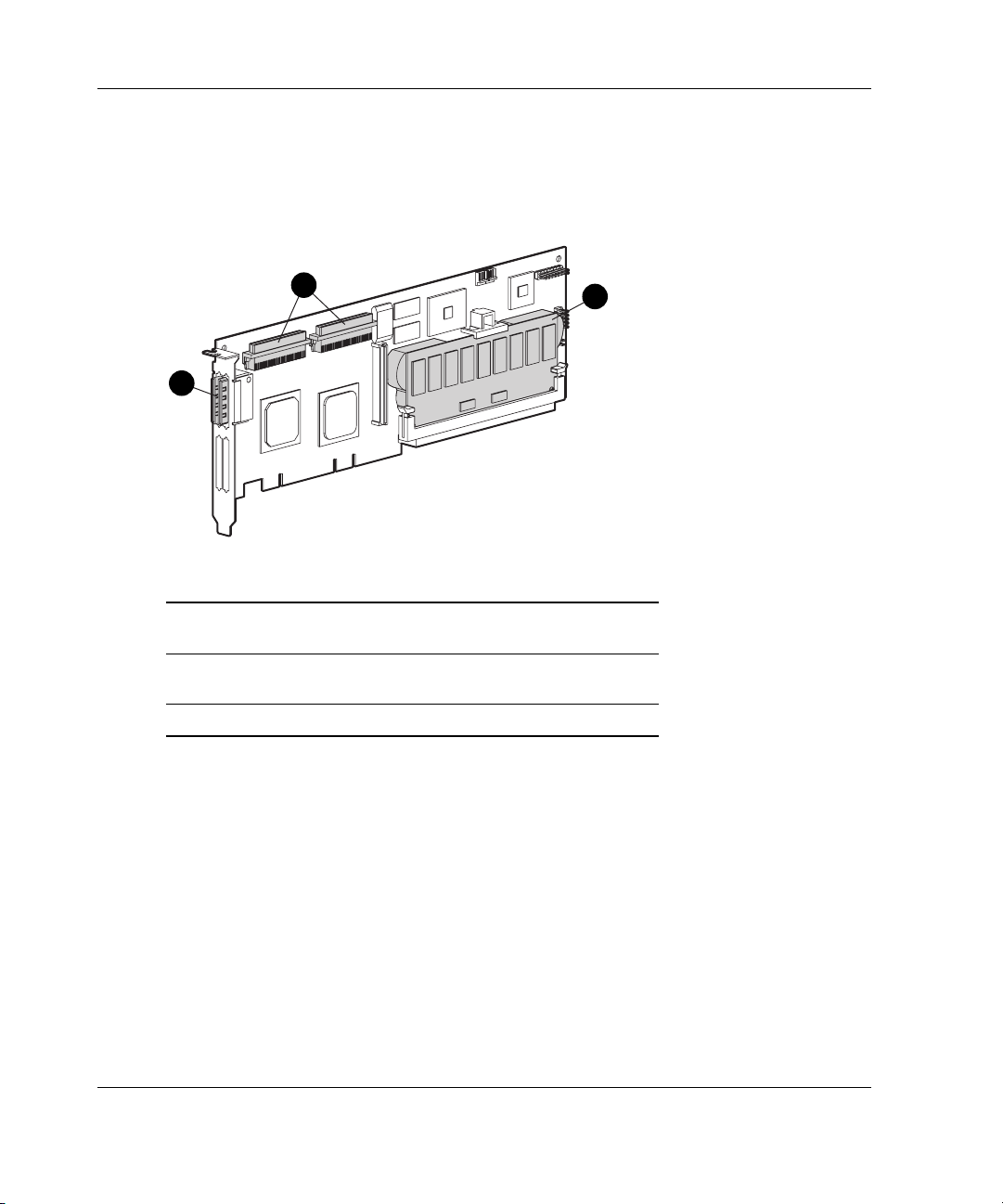
1
3
2
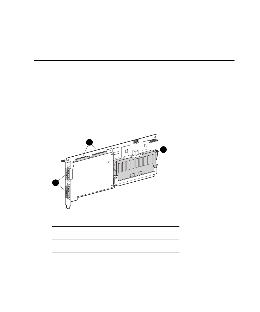
Figure 1-1: Smart Array 5304 Controller
Item Description
1 Two internal 68-pin Wide SCSI connectors (port 1
nearer the bracket, port 2 nearer the board center)
2 Four external (VHDCI) connectors (ports 1 and 3
nearer the main board)
3 Array accelerator cache
HP Smart Array 5300 Controller User Guide 1-1
Page 14
Board Components and Features
NOTE: On both controller models, ports 1 and 2 each have two connectors (one internal and
one external). However, only one connector can be used per port at any given time. Ports 3
and 4 (available on the 5304) can be used only for external drives.
1
2
Figure 1-2: Smart Array 5302 Controller
Item Description
1 Two internal 68-pin Wide SCSI connectors (port 1
nearer the bracket, port 2 nearer the board center)
2 Two external (VHDCI) connectors (port 1 nearer the
board)
3 Array accelerator cache
3
1-2 HP Smart Array 5300 Controller User Guide
Page 15
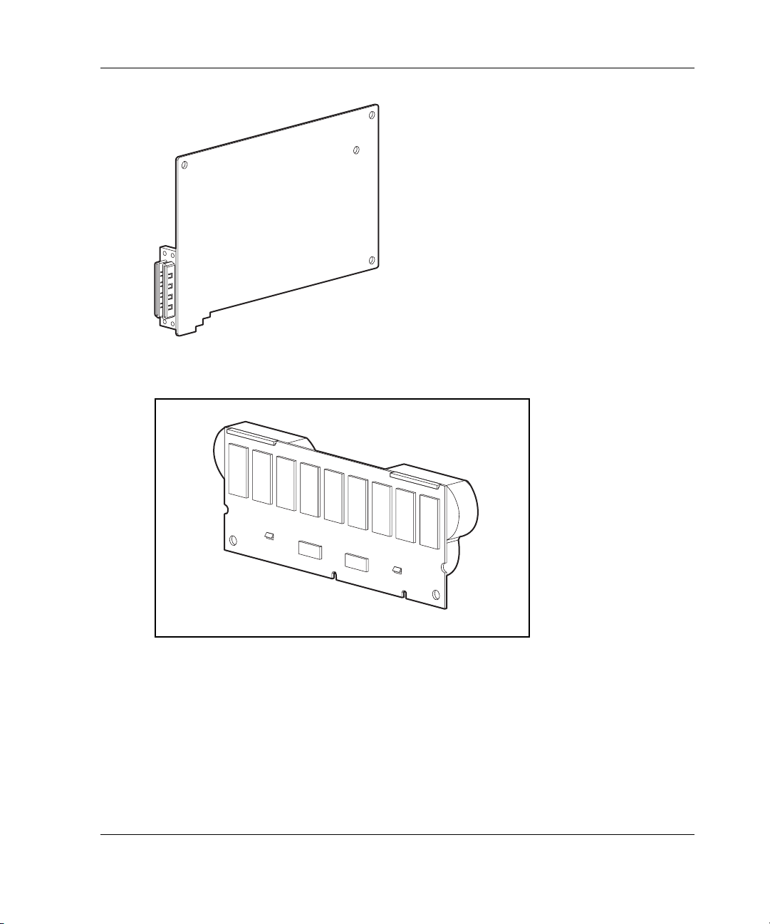
Figure 1-3: Two- to four-channel adapter upgrade
option
Board Components and Features
Figure 1-4: Array accelerator cache with batteries
For details of the controller board specifications, refer to Appendix C.
HP Smart Array 5300 Controller User Guide 1-3
Page 16

Board Components and Features
Overview of Controller Features
• Two or four Wide Ultra3 SCSI channels, supporting up to 56 drives (4 channels,
14 drives per channel)
• Support for Microsoft Windows 2000, Windows NT 4.0, Linux, Novell NetWare
5.x, and NetWare 6 operating systems
• Support for the Universal Hot Plug Tape Drive, with storage capacity up to 100
GB and LVD transfer rates up to 12 MB per second
• Support for the StorageWorks SAN Access Module
• Backward compatibility with Wide Ultra2 devices
• Removable array accelerator
• 64-bit, 66-MHz PCI system interface
• Other features supported:
— RAID fault-tolerance (0, 1+0, 5, ADG) (refer to Chapter 9 for instructions on
enabling RAID ADG)
— Online RAID migration between any two levels
— Online array capacity expansion
— Online logical drive capacity extension
— Hot-pluggable hard drives and tape drives
— Drive movement
— Adjustable stripe size
— Performance monitoring through Insight Manager
— S.M.A.R.T. hard drives
— Drive pre-failure notification
— Multiple online spares per array
— Tagged command queuing
— Background initialization
— Multiple logical drives per array
1-4 HP Smart Array 5300 Controller User Guide
Page 17

Board Components and Features
Overview of Array Accelerator Features
The array accelerator is a high performance, battery-backed, 100-MHz SDRAM
DIMM cache module.
Array controllers use cache to store read data from the hard drives. The system can
later access this read data. The controller firmware uses the read-ahead and most
recently used caching algorithms.
Array controllers also use cache to complete drive write operations more quickly.
This use of the cache has further performance benefits:
• If the system requires data that still resides in write cache, the controller delivers
this data from the cache. This process is quicker than delivering the data from a
drive.
• If the system writes new data to the same location, the controller overwrites the
cache contents. This eliminates a drive write operation.
• If the system performs a RAID 1 procedure, the controller gets mirrored data
from the cache instead of from host memory.
• If the system performs a RAID 5 procedure, the write cache collects enough data
blocks from several write accesses to carry out a full stripe write to the hard
drives. This operation eliminates the need to calculate and update parity
information each time that a data block is written to the drive.
With a battery-backed cache available, the array controller can complete the
following operations more rapidly:
• Array capacity expansion—the expansion of a logical drive volume to include
more hard drives
• Stripe size migration—the adjustment of the size of data blocks within a stripe,
done to improve performance
• RAID level migration—the adjustment of RAID level to improve the fault
tolerance of the array
HP Smart Array 5300 Controller User Guide 1-5
Page 18

Board Components and Features
For each of these operations, data has to be reorganized among hard drives, and must
be saved to non-volatile storage during the operation. (For further details of these
operations, refer to Chapter 7, Appendix D, and Appendix E.) Without batterybacked cache, the data can only be stored at empty locations within the drive array,
so these operations cannot occur at all if the array is full.
If the array controller or server fails before cached data can be stored on the array, the
array accelerator and its integrated batteries may be removed from one array
controller and installed on another controller of the same type. Any data in the array
accelerator that has not been written to the hard drive will be transferred to the other
array controller.
Other features of the array accelerator include:
• Cache capacity of 96-MB or 224-MB (32 MB of the cache is used for transfer
buffer)
• Adjustable read/write ratio (usually set during array configuration as described in
Chapter 7, but can be changed at any time)
• Error checking and correcting (ECC) memory, providing single-bit data
correction
Sometimes, the Automatic Performance Tuning feature disables the array accelerator.
You can also disable the array accelerator manually through the Array Configuration
Utility (refer to Chapter 7 for details).
Batteries
The array accelerator cache has two rechargeable and replaceable NiMH battery
packs. If the array accelerator is removed from the array controller, the battery packs
maintain any cached data on the array accelerator for up to four continuous days.
1-6 HP Smart Array 5300 Controller User Guide
Page 19
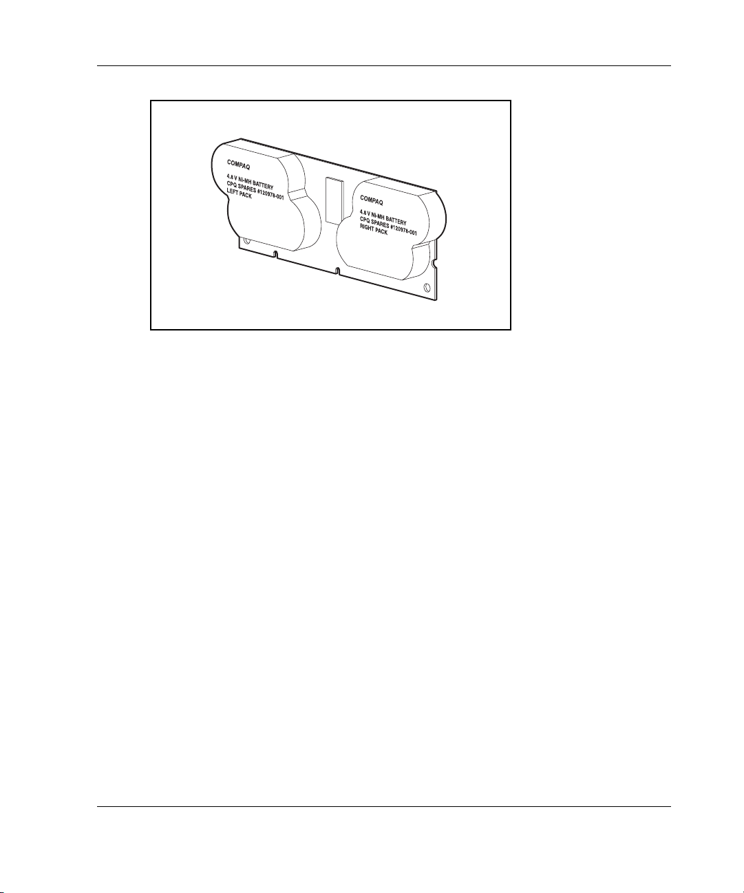
Board Components and Features
Figure 1-5: Battery packs
This data protection (and the time limit) also applies if an equipment failure or power
outage occurs. When power is restored to the system, an initialization process writes
the preserved data to the hard drives.
The batteries are continuously recharged using a trickle-charging process whenever
the system power is on. Under normal operating conditions, a battery pack lasts for
three years before replacement is necessary.
IMPORTANT: The batteries on a new array controller may have a low charge when the
controller board is first installed. In this case, a Power-On Self-Test (POST) message 1794 is
displayed when the server is powered up (refer to Appendix G), indicating that the array
accelerator is temporarily disabled. No action is required on your part, since the internal
circuitry automatically recharges the batteries and enables the cache. The recharge process
takes less than four hours. The array controller will function properly during this time, although
without the performance advantage of the array accelerator. When the batteries are charged to
an acceptable capacity, the array accelerator is automatically enabled.
For battery replacement instructions, refer to Chapter 9.
HP Smart Array 5300 Controller User Guide 1-7
Page 20

Board Components and Features
PCI System Interface
Smart Array 5300 controllers interface to the server through a high-performance
64-bit PCI bus that:
• Runs at 66 MHz
• Provides a high-speed path (up to 528 MB/s) between the system board and the
controller
• Includes two parity protection signals
The Smart Array 5300 Controller is a PCI Bus Master device conforming to Rev. 2.2
of the PCI Local Bus Specification. As a bus master device, it takes control of the
PCI bus during high-speed transfers, freeing the system processor to handle
application processing or other types of tasks.
For maximum performance, HP recommends that you use only 66-MHz devices on
any given 66-MHz PCI bus. Combining 66-MHz and 33-MHz devices on a PCI bus
will decrease the overall bandwidth to 33-MHz speeds.
SCSI Support
The Smart Array 5300 Controller supports drives that conform to Wide Ultra3 and
Wide Ultra2 standards. Although Wide Ultra2 devices operate at a different
maximum speed from Wide Ultra3 devices, operating speeds are unaffected if they
are connected to the same SCSI bus because they both use low voltage differential
(LVD) signaling.
Fault Management Features
The array controller and the network operating system support several fault
management and data reliability features that minimize the impact of hard drive
defects on your system.
1-8 HP Smart Array 5300 Controller User Guide
Page 21

Board Components and Features
• Auto-Reliability Monitoring (ARM) is a background process that scans hard
drives for bad sectors in fault-tolerant logical drives. ARM also verifies the
consistency of parity data in logical drives that are using RAID 5 or RAID ADG.
This process assures that you can recover all data successfully if a drive failure
occurs in the future. ARM operates only when you select a fault-tolerant
configuration (RAID 1 or higher).
• Dynamic sector repair by the controller automatically remaps any sectors that
have media faults (detected either during normal operation or by auto reliability
monitoring).
• S.M.A.R.T. is an industry-standard diagnostic and failure-prediction feature of
hard drives, developed in collaboration with the hard drive industry. It monitors
several factors that can be used to predict imminent hard drive failure due to
mechanical causes. Such factors include the condition of the read/write head, the
seek error rate, and the spin-up time. When a threshold value is exceeded for one
of these factors, the drive sends an alert that failure is imminent. Thus, the user
can back up data and replace the drive before drive failure occurs.
NOTE: An online spare does not become active and start rebuilding when the imminent
failure alert is sent, because the degraded drive has not actually failed yet and is still
online. The online spare is activated only after a drive in the array has failed.
• Drive failure alert features cause an alert message to be displayed on the
system monitor when drive failure occurs. Different server models use different
messages for different situations. These messages are described in your server
documentation.
• Interim data recovery occurs if a drive fails in fault-tolerant configurations
(RAID 1 or higher). In this situation, the system will still process I/O requests,
but at a reduced performance level. Replace the failed drive as soon as possible
to restore performance and full fault tolerance for that logical drive. Otherwise, if
another hard drive fails before data has been rebuilt, the logical volume will fail
and data will be lost. Refer to Appendix E for more information about recovering
from drive failure.
• POST or the Array Diagnostics Utility will also reveal imminent drive failure.
HP Smart Array 5300 Controller User Guide 1-9
Page 22

Board Components and Features
• Recovery ROM is a redundancy feature that ensures continuous system
availability by providing a backup ROM. This feature protects against corruption
of a ROM image (caused, for example, by power fluctuation during ROM
upgrade). If corruption occurs, the server automatically restarts using the
remaining good copy of the ROM image.
When you upgrade the ROM, the inactive image (the one not being used by the
system) is upgraded. There is not normally any noticeable difference in
operation. When you use Recovery ROM for the first time, however, both ROM
images are upgraded, causing a boot delay of about 60 seconds.
Other options, such as Insight Manager, provide additional drive failure features.
Refer to your authorized reseller for more information about these products.
1-10 HP Smart Array 5300 Controller User Guide
Page 23
The details of the steps required to install the controller depend on whether the server
has an operating system installed and contains data. The flowcharts in Figure 2-1 and
Figure 2-2 summarize the installation procedures for the most common scenarios.
Procedure for a New System
Install the controller
1
hardware (Chapter 3), if
it is not pre-installed.
Set the boot controller
5
(Chapter 6).
Create at least one
6
logical drive and format
it (Chapter 7).
Install the operating
7
system and device
drivers (Chapter 8).
:
:
. . . . . . .
. . . . . . .
. . . . . . .
Installation Overview
Update the system
2
firmware (Chapter 4).
Update the controller
3
firmware (Chapter 5).
Configure the system
4
(Chapter 6).
Create and format
8
additional logical drives
if desired (Chapter 7).
:
:
2
Figure 2-1: Controller installation in a new system
HP Smart Array 5300 Controller User Guide 2-1
Page 24
Installation Overview
Procedure for a Pre-configured System
Back up data (required if migrating
1
from a non-array controller).
Set the controller order (Chapter 6).
5
Update the controller firmware
6
(Chapter 5).
If using the System Configuration
7
Utility, update the system partition
(Chapter 5), and then check the
controller order (Chapter 6).
If migrating from a non-array
11
controller, restore data from backup.
:
:
- - - - -
- - - - -
- - - - -
- - - - -
Update the system firmware
2
(Chapter 4).
If the controller is to be the boot
3
device, install the device driver for
your operating system (Chapter 8).
Otherwise, continue with step 4.
Install the controller hardware
4
(Chapter 3).
If the controller is not to be the boot
8
device, install the device driver for
your operating system (Chapter 8).
Update Insight Manager Agents if
9
new versions are available (Chapter
8).
Create and format logical drives as
10
desired (Chapter 7).
:
:
:
:
Figure 2-2: Controller installation in an already
configured system
2-2 HP Smart Array 5300 Controller User Guide
Page 25
Preparing the Server
Before installing the controller in the server, back up all data. This step is mandatory
if you are moving non-arrayed SCSI drives to a Smart Array controller, because data
is not preserved during a move between array controllers and non-array controllers.
WARNING: To reduce the risk of personal injury or damage to the equipment,
consult the safety information and user documentation provided with your
computer before attempting the installation.
Many computers are capable of producing energy levels that are considered
hazardous. These computers are intended to be serviced by qualified
personnel trained to deal with those hazards. Do not remove enclosures or
attempt to bypass any interlocks that may be provided for the purpose of
removing these hazardous conditions.
3
Installing the Hardware
If your server supports hot-pluggable devices, go directly to the section, “Installing
the Smart Array Controller.”
To prepare a server that does not support hot-pluggable devices:
1. Close all applications.
2. Power down the server.
CAUTION: In systems using external data storage, be sure that the server is the
first unit powered down and the last unit to be powered back up. Doing this
ensures that the system will not erroneously mark the drives as “failed.”
3. Power down any peripheral devices that are attached to the server.
HP Smart Array 5300 Controller User Guide 3-1
Page 26
Installing the Hardware
4. Unplug the AC power cord from the outlet, and then from the server.
IMPORTANT: If you will be replacing a Smart controller with a Smart Array controller, see
the “External Cabling for HP Servers” section to determine the external cabling
requirements.
5. Disconnect any peripheral devices from the server.
WARNING: To reduce the risk of personal injury from hot surfaces, allow
the internal system components and hot-plug hard drives to cool before
touching them.
CAUTION: Electrostatic discharge (ESD) can damage electronic components.
Be sure that you are properly grounded before continuing the installation
procedure. See Appendix B for ESD information.
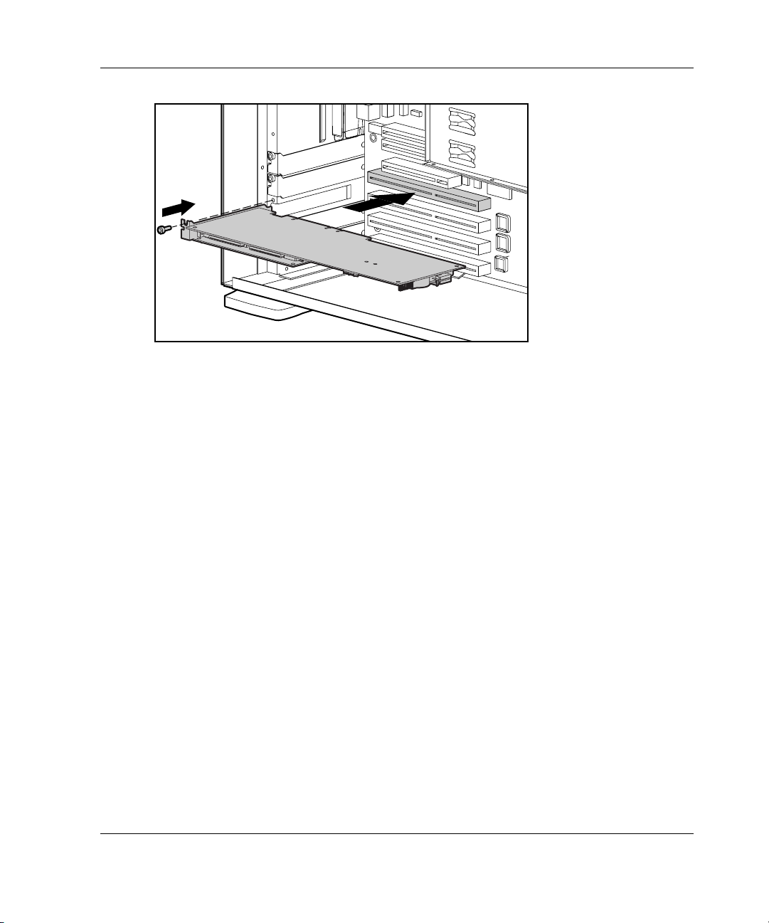
Installing the Smart Array Controller
1. Remove or open the access panel.
2. Select an available 66-MHz PCI slot. Slots that use a 64-bit interface may
provide higher performance.
3. Remove the slot cover or open the hot-plug latch. Save the retaining screw, if one
is present.
4. Slide the controller board along the slot alignment guide.
3-2 HP Smart Array 5300 Controller User Guide
Page 27
Installing the Hardware
Figure 3-1: Installing a Smart Array 5300 Controller
NOTE: Your server may look slightly different from the one illustrated.
5. Press the controller board firmly into the slot so that the contacts on the board
edge are properly seated in the system board connector.
6. Secure the board in place with the hot-plug latch or retaining screw.
7. Continue by following the instructions given in “Connecting the Cables.”
Connecting the Cables
Each port on the controller supports up to 14 drives. Ports 1 and 2 each have two
SCSI connectors, one for external storage units and one for internal hard drives in the
server. The two connectors for a given port cannot be used simultaneously. Ports 3
and 4 (present on the 5304 model, and also on the 5302 model with an attached 2- to
4-channel adapter) are only for external storage units.
Peripherals attached to any of the connectors must have a unique SCSI ID value in
the range of 0 to 15 (except ID 7, which is reserved for controller use). The SCSI ID
value determines the priority given to the device when it attempts to use the SCSI
bus.
HP Smart Array 5300 Controller User Guide 3-3
Page 28

Installing the Hardware
On HP and Compaq-branded products that support hot-pluggable drives, the SCSI
IDs for peripherals are automatically set. For non-hot-pluggable devices, the IDs
must be set manually by using switches or jumpers on the device itself.
IMPORTANT: When replacing an existing Smart controller with a Smart Array controller
without reconfiguring the arrays, all of the drives should be connected exactly as they were on
the old controller (port 1 to port 1, controller 1 to controller 1, and so on).
SCSI buses require termination on both ends to prevent signal degradation. In HP and
Compaq-branded servers and storage systems, however, the controller, SCSI cable,
and backplane already provide this termination.
Internal Cabling for HP Servers
1. If the device is not hot pluggable, power down the system.
2. Install drives into the removable media bays on the server. Drives that are to be
grouped in the same array should have the same capacity.
For detailed drive installation instructions, consult the documentation that
accompanied your drives.
The exact procedure from this point depends upon whether the device is hot
pluggable.
— If the drives are hot pluggable, go to step 3.
— If the drives are not hot pluggable, go to step 4.
3. Attach the internal point-to-point SCSI cable (provided with your server) from an
internal port of the controller to the hot-plug drive cage.
For duplex drive cage options, use both internal ports.
The hot-pluggable drives are now ready to use.
4. For each SCSI bus, manually set the SCSI ID on each drive to a unique value in
the range of 0 to 15, except 7 (which is reserved for controller use). For detailed
instructions, consult the documentation that is provided with the drive.
5. Attach the multi-device SCSI cable from the internal port 1 or port 2 of the Smart
Array controller to the non-hot-pluggable hard drives.
3-4 HP Smart Array 5300 Controller User Guide
Page 29
The multi-device cable may have been provided with your server. If you need
additional cables, order the cable option kit, Part Number 166389-B21. This
cable is equipped to terminate either Wide Ultra3 or Wide Ultra2 drives.
CAUTION: Cable assembly 148785-001 is included in option kit 166389-B21
and is required with Wide Ultra3 drives. Failure to use this cable may result in
reduced performance and/or data loss.
For additional information about drive installation, see Appendix E.
External Cabling for HP Servers
All HP and Compaq-branded Storage Enclosure models include external SCSI
cables. Check the connector type on your storage device to identify the cable type
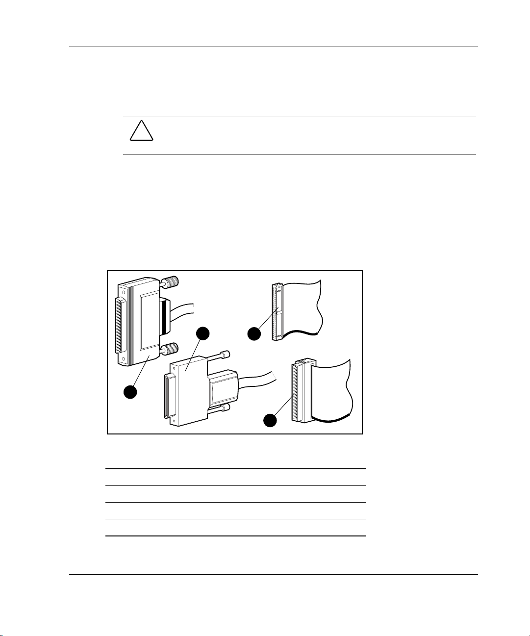
needed. See Figure 3-2 and Table 3-1 for details.
Installing the Hardware
2
1
3
4
Figure 3-2: Identifying SCSI cable connectors
Item Description
1 External 68-pin Wide
2 External offset VHDCI
3 Internal 50-pin narrow
4 Internal 68-pin Wide
HP Smart Array 5300 Controller User Guide 3-5
Page 30

Installing the Hardware
Table 3-1: External SCSI Cables for Enclosures
Cable Type Length Option Kit Number Cable Assembly Number
VHDCI to VHDCI 1.8 m / 6 ft 341174-B21 313374-001
VHDCI to VHDCI
VHDCI to VHDCI 7.2 m / 24 ft 164604-B21 313374-004
VHDCI to VHDCI 11.7 m / 39 ft 150214-B21 313374-005
VHDCI to Wide 1.8 m / 6 ft
VHDCI to Wide 3.6 m / 12 ft 341177-B21 313375-002
Note: If additional cables are required, order by the option kit number.
3.6 m / 12 ft
341175-B21 313374-002
341176-B21 313375-001
Up to four SCSI ports may be available for connection to external storage devices
depending on whether the 2- to 4-channel adapter is attached and whether internal
drives are connected to the array controller.
1. On the rear of the server, connect the cable to the VHDCI connector on the Smart
Array controller, and then tighten the lock screws on the cable connector.
IMPORTANT: Offset VHDCI cables must be used with the Smart Array 5300 controller.
Early versions of the VHDCI cables do not accommodate side-by-side connection of the
cables to the Smart Array 5300 controller. If your storage enclosure did not include the
Offset VHDCI cables, you may need to order these. See Table 4-1 for part numbers.
NOTE: Do not use a port externally if it is already being used internally.
2. Attach the other end of the cable to the storage enclosure, and then tighten the
lock screws on the cable connector.
3. Replace the access panel and secure it with the thumbscrews, as required.
CAUTION: Do not operate the server with the access panel removed for
extended periods of time. This precaution is to protect thermally sensitive
components by ensuring the proper airflow through the server, and also to
minimize personal contact with hazardous energy levels.
3-6 HP Smart Array 5300 Controller User Guide
Page 31

4
Updating the System Firmware
To update the system firmware, the System ROMPaq utility is used.
NOTE: This utility is not to be confused with the Options ROMPaq utility (refer to Chapter 5),
which is used to update the firmware on server options and SCSI drives.
This utility has two main sources:
• The SmartStart CD that is either shipped with your server or available directly
from HP
• The downloadable SoftPaq file on the HP website
If your server has a bootable CD-ROM drive, you can run System ROMPaq directly
from the CD. Otherwise, you must run System ROMPaq from a diskette created from
either the CD or from the SoftPaq file.
IMPORTANT: Compare the version numbers of the System ROMPaq utility from these two
sources. If the CD version is older, use the SoftPaq file instead.
Running System ROMPaq from the CD
1. Boot the server from the SmartStart CD.
2. On the System Utilities screen, select Run ROMPaq.
3. Follow the on-screen prompts and instructions to reprogram your system ROM.
HP Smart Array 5300 Controller User Guide 4-1
Page 32

Updating the System Firmware
Running System ROMPaq from Diskette
To run System ROMPaq from diskette, you must first create a System ROMPaq
diskette from the CD or from the appropriate SoftPaq file.
Creating a System ROMPaq Diskette from the CD
1. Insert the SmartStart CD into the CD-ROM drive tray of a server with a bootable
CD-ROM drive.
2. Restart the server.
3. On the System Utilities screen, select Create Support Software.
4. On the Diskette Builder screen, scroll through the list and select System
ROMPaq Firmware Upgrade Diskette, and then click Next.
5. Select Create Diskettes Only, and then click Next.
6. Follow the remaining instructions on the screen to create the System ROMPaq
diskette.
7. To update the firmware, follow the procedure given in “Using the Diskette.”
Creating a System ROMPaq Diskette from the SoftPaq File
1. Create a temporary directory on your hard drive.
2. Go to
3. Click the link for the System ROMPaq SoftPaq file.
4. Click Download, and direct the download to the temporary directory that you
5. Click Save.
6. Execute the downloaded SoftPaq file and follow the on-screen instructions to
7. To update the firmware, follow the procedure given in “Using the Diskette.”
4-2 HP Smart Array 5300 Controller User Guide
www.hp.com and locate the page containing the SoftPaq file for the System
ROMPaq utility.
created.
create the System ROMPaq diskette.
Page 33

Using the Diskette
1. With the server powered down, place the System ROMPaq diskette in the
diskette drive.
2. Power up the server.
3. When the Welcome screen is displayed, press the Enter key.
4. When the Select A Device screen is displayed, select your server from the list of
programmable devices, and then press the Enter key.
The Select An Image screen is displayed, showing the following information:
Device to reprogram: your server
Current ROM revision: date of existing ROM version
Select Firmware Images: date of latest ROM version
5. Press the Enter key. The Caution screen is displayed.
6. Press the Enter key. The following message is displayed:
Reprogramming Firmware
Do not interrupt the reprogramming process. You will be notified when
reprogramming is complete.
Updating the System Firmware
7. When reprogramming has finished, press the Esc key to exit the utility.
8. Remove the System ROMPaq diskette and restart the server.
HP Smart Array 5300 Controller User Guide 4-3
Page 34

5
Updating the Controller Firmware
You can update the firmware on HP and Compaq-branded options by using the
Options ROMPaq utility. There are two versions of this utility: Options ROMPaq for
Array Controllers, and Options ROMPaq for Internal (SCSI Attached) Drives.
If you purchased your server with an array controller already installed, you do not
need to run this utility during server installation. However, if you have older Smart
Array Controllers or other HP or Compaq-branded options (such as drives), run
Options ROMPaq to make sure that these devices have the latest firmware. HP
recommends that you run the latest Options ROMPaq on all HP or Compaq-branded
array controllers whenever new versions of the utility are released.
The Options ROMPaq utility has three main sources:
• The SmartStart CD
• The Smart Array Controller Support Software CD
• The downloadable SoftPaq file on the HP website
If your server has a bootable CD-ROM drive, you can run Options ROMPaq directly
from the CD. Otherwise, you must run Options ROMPaq from a diskette created
from the CD or from the SoftPaq file.
IMPORTANT: Compare the version numbers of the Options ROMPaq utility from these
sources. If the CD version is older, use the SoftPaq file instead.
If your system uses the System Configuration Utility (SCU), you might also need to
update the system partition to complete the system update.
HP Smart Array 5300 Controller User Guide 5-1
Page 35

Updating the Controller Firmware
Running Options ROMPaq from the CD
1. Place the CD in the server CD-ROM drive.
2. Restart the server.
3. When the System Utilities Menu screen is displayed, select Run Options
ROMPaq, and then press the Enter key.
4. When the Welcome screen is displayed, press the Enter key.
5. On the Select A Device screen, select All Compaq Smart Array 5300
Controller(s)
key.
6. The action that you must now take depends on the message on the screen.
— If the screen message reads as follows, press the Enter key, and then go to
step 8 of these instructions:
The ROM image files found for the device selected are not
newer than the current ROM image
— If the ROM firmware currently on the controller is older than that on the
Options ROMPaq diskette, then the screen message reads as follows:
Device to reprogram: All Compaq Smart Array 5300
Controller(s)
Controller(s) Current ROM revision: Compaq Smart Array
5300 Controller x.xx
Select Firmware Images: Compaq Smart Array 5300
Controller y.yy
from the list of programmable devices, and then press the Enter
In this case, press the Enter key and then go to step 7.
7. Review the information on the Caution screen, and then press the Enter key to
reprogram the controller ROM.
The following message is displayed:
Reprogramming Firmware
Do not interrupt the reprogramming process. You will be notified when
reprogramming is complete.
5-2 HP Smart Array 5300 Controller User Guide
Page 36

Updating the Controller Firmware
8. When reprogramming of the controller ROM is finished, you can reprogram
more options or exit the utility.
— To reprogram another option, press the Enter key, and then repeat steps 5
through 7.
— If you have finished reprogramming options, press the Esc key to exit the
utility.
9. Remove the CD and restart the server.
Running Options ROMPaq from Diskettes
To run Options ROMPaq from diskettes, first create Options ROMPaq diskettes from
one of the CDs or from the appropriate SoftPaq file.
Creating Diskettes Using the Smart Array Controller Support Software CD
1. Insert the Smart Array Controller Support Software CD into the server CD-ROM
drive tray.
2. Open the OPTRMDSK folder on the CD and execute the QRST5.EXE file.
3. Follow the on-screen prompts to create the set of Options ROMPaq diskettes.
4. To complete the firmware update, follow the procedure given in the section,
“Using the Diskettes.”
Creating Diskettes Using the SmartStart CD
1. Insert the SmartStart CD into the CD-ROM drive tray of a server with a bootable
CD-ROM drive.
2. Restart the server.
3. On the System Utilities screen, select Create Support Software.
4. On the Diskette Builder screen, scroll through the list and select Options
ROMPaq, and then click Next.
HP Smart Array 5300 Controller User Guide 5-3
Page 37

Updating the Controller Firmware
5. Choose Create Diskettes Only and then click Next.
6. Follow the remaining on-screen instructions to create the Options ROMPaq
diskettes.
7. To complete the firmware update, follow the procedure given in the section,
“Using the Diskettes.”
Creating Diskettes Using the SoftPaq File
1. Create a temporary directory on your hard drive.
2. On the HP website, locate the page containing the SoftPaq file for the Options
ROMPaq utility.
3. Click the link for the Options ROMPaq SoftPaq file.
4. Click Download, and direct the download to the temporary directory that you
created.
5. Click Save.
6. Execute the downloaded SoftPaq file and follow the on-screen instructions to
create the diskette. Up to six diskettes are needed for the Options ROMPaq
SoftPaq file.
7. To complete the firmware update, follow the procedure given in the section,
“Using the Diskettes.”
Using the Diskettes
1. Confirm that the server is off.
2. Insert the first Options ROMPaq diskette into the diskette drive.
3. Restart the server.
4. When the Welcome screen is displayed, press the Enter key.
The Select a Device screen is displayed.
5-4 HP Smart Array 5300 Controller User Guide
Page 38

Updating the Controller Firmware
5. If the controller that you want to update the firmware for is on the list of
programmable devices, select it and press the Enter key. (If it is not present, you
are prompted to insert the remaining diskettes for devices not listed on the first
diskette.)
6. The action that you must now take depends on the message on the screen.
— If the screen message reads as follows, press the Enter key, and then go to
step 8 of these instructions:
The ROM image files found for the device selected are not
newer than the current ROM image
— If the ROM firmware currently on the controller is older than that on the
Options ROMPaq diskette, then the screen message reads as follows:
Device to reprogram: All Compaq Smart Array nnnn
Controller(s)
Controller(s) Current ROM revision: Compaq Smart Array
nnnn Controller x.xx
Select Firmware Images: Compaq Smart Array nnnn
Controller y.yy
In this case, press the Enter key and then go to step 7.
7. Review the information on the Caution screen, and then press the Enter key to
reprogram the controller ROM.
The following message is displayed:
Reprogramming Firmware
Do not interrupt the reprogramming process. You will be notified when
reprogramming is complete.
8. When the reprogramming of the array controller ROM is finished, you can
reprogram more options or exit the utility.
— To reprogram another option, press the Enter key, and then repeat steps 5
through 7.
— If you have finished reprogramming options, press the Esc key to exit the
utility.
9. Remove the Options ROMPaq diskette and restart the server.
HP Smart Array 5300 Controller User Guide 5-5
Page 39

Updating the Controller Firmware
Updating the System Partition
If you are installing the controller on a server that was previously configured with
SCU, you must now use this utility to update the system partition.
NOTE: If your server uses the ROM-Based Setup Utility (RBSU), you do not need to run SCU.
SCU is provided on both the SmartStart CD and the Smart Array Controller Support
Software CD. Compare the SCU version numbers from these two sources and use the
most recent version.
NOTE: Before updating Novell NetWare volumes or partitions, remember these tips to
optimize system performance:
• If you want to use hardware-based RAID, do not select mirroring while using
INSTALL.NLM or NWCONFIG.NLM.
• Novell recommends that you create volumes with a 64-kbyte block size to decrease the
amount of RAM required to mount the volume, and use the Block Sub-Allocation feature
to allow disk space to be allocated more efficiently.
• Linear memory provides the best system performance in the NetWare environment. If you
previously used SCU to configure your server, this option would have been the default. To
check that the system is using linear memory, run SCU and view the Memory settings.
Confirm that a linear option is selected under the Base Memory option.
1. Restart the server from the CD.
2. If the CD-ROM drive is bootable, go to step 5. Otherwise, locate the CD-ROM
drive:\SYSCFDSK\US directory, run the file QRST5.EXE, and follow the onscreen instructions to create four SCU diskettes.
3. Insert SCU diskette #1 into the server diskette drive.
4. Restart the system.
5. Select System Configuration Utility from the menu or list of icons that is
displayed.
6. Follow the on-screen instructions to update or create and populate a system
partition.
7. Exit from SCU. If the server does not reboot or a CD error message is displayed,
press the Ctrl+Alt+Del keys to continue and reboot the server.
5-6 HP Smart Array 5300 Controller User Guide
Page 40

After installing the controller hardware and updating the controller firmware:
• Configure the system by using either the ROM-Based Setup Utility (RBSU) or
the System Configuration Utility (SCU), following the procedure given in the
server user guide.
• Set the boot controller by using RBSU or the Option ROM Configuration for
Arrays (ORCA) utility (described in this chapter).
• Create at least one logical drive by using ORCA or ACU (as described in
Chapter 7).
Using RBSU
RBSU is a system configuration utility that is embedded in the system ROM, and is
customized for the server that it is installed on. Update RBSU when necessary by
using System ROMPaq.
CAUTION: Not all servers support RBSU. Do not flash an RBSU-ROM image onto a
server that is already configured with SCU unless the update instructions specifically
state that upgrading from SCU to RBSU is supported. If the upgrade is not
supported, the consequences of upgrading are unpredictable and you may lose data.
6
Setting the Controller Order
HP Smart Array 5300 Controller User Guide 6-1
Page 41

Setting the Controller Order
To use RBSU:
1. Power up the server.
2. Press the F9 key when prompted during system startup.
The main ROM-Based Setup Utility screen is displayed.
Figure 6-1: Main ROM-Based Setup Utility screen
3. Configure your system. (For detailed instructions, refer to the HP ROM-Based
Setup Utility User Guide.)
4. Select Boot Controller Order on the main RBSU screen and follow the on-
screen prompts to set the boot controller.
5. When you have finished using the utility, press the Esc key, and then press the
F10 key to confirm that you want to exit RBSU.
Using ORCA
Part of the startup sequence of a server is the Power-On Self-Test (POST). If the
array controller in the server supports ORCA, POST temporarily halts and an ORCA
prompt message is displayed for about five seconds. (If ORCA is not supported, the
prompt message is not displayed and the system continues with the startup sequence.)
1. Power up the server and let the system startup sequence begin.
2. While the prompt message is on the screen, press the F8 key to start ORCA.
6-2 HP Smart Array 5300 Controller User Guide
Page 42

Setting the Controller Order
3. On the Option ROM Configuration for Arrays Main Menu screen, select
Select as Boot Controller and follow the prompts to set the boot controller for
the system.
If you want to use ORCA to create logical drives at this point, you do not need to exit
the utility yet. Continue using ORCA as described in Chapter 7.
HP Smart Array 5300 Controller User Guide 6-3
Page 43

7
Configuring an Array
HP provides four utilities for configuring an array:
• Option ROM Configuration for Arrays (ORCA)—a simple ROM-based
configuration utility that runs on all operating systems
• Array Configuration Utility (ACU)—a versatile configuration utility that
provides maximum control over configuration parameters
• Array Configuration Utility 6.0 (ACU 6.0)—a browser-based version of ACU
• NetWare Online Array Configuration Utility (CPQONLIN)—a menu-driven
utility for NetWare
The following limitations apply to all configuration methods:
• For the most efficient use of drive space, do not mix drives of different capacity
within the same array. Each configuration utility treats all physical drives in an
array as if they have the same capacity as the smallest drive in the array. Excess
capacity of larger drives is wasted because it is unavailable for data storage.
• The probability that an array will experience a hard drive failure increases with
the number of hard drives in the array (for more detailed information, refer to
Appendix F). If you configure an array with RAID 5, keep the probability of
failure acceptably low by using no more than 14 drives.
This chapter describes how to use ORCA, ACU, and CPQONLIN. For detailed
information about using ACU 6.0, refer to the HP Array Configuration Utility 6.0
User Guide. For background information about drive arrays and fault-tolerance
(RAID) methods, refer to Appendix D.
HP Smart Array 5300 Controller User Guide 7-1
Page 44

Configuring an Array
Table 7-1: Comparison of Utilities for Configuring an Array
ACU ACU 6.0 CPQONLIN ORCA
Uses a graphical interface + + 0 0
Available in languages other than English + + 0 0
Executable at any time + + + 0
Available on CD + + + 0
Uses a wizard to suggest the optimum
configuration for an unconfigured controller
Describes configuration errors + + 0 0
Supports these operating systems:
Windows 2000 + + 0 +
Windows NT + + 0 +
NetWare +* +* + +
Linux +* + 0 +
Allows these procedures:
Creation and deletion of arrays, logical drives + + + +
Assignment of RAID level + + + +
Sharing of spare drive among several arrays + + + 0
Assignment of multiple spare drives per array + + + 0
Setting of stripe size + + + 0
Migration of RAID level or stripe size + + + 0
Configuration of controller settings + + + 0
Expansion of an array + + + 0
Creation of multiple logical drives per array + + + +
Setting of boot controller 0 0 0 +
+ + + 0
*An array can be configured in these cases only when the system is offline.
7-2 HP Smart Array 5300 Controller User Guide
Page 45

Using ORCA
When a computer system is powered up, part of the startup sequence is the Power-On
Self-Test (POST). Any array controllers that are in the system are initialized while
POST is running. If the array controller supports ORCA, POST temporarily halts and
an ORCA prompt message is displayed for about five seconds. (If ORCA is not
supported, the prompt message is not displayed and the system continues with the
startup sequence.)
While the prompt is displayed, press the F8 key to start ORCA. The ORCA main
menu is displayed, allowing you to select the boot controller for the system, or to
create, view, or delete a logical drive.
Configuring an Array
Figure 7-1: ORCA main menu screen
To create a logical drive:
1. Select Create Logical Drive.
The screen displays a list of all available (unconfigured) physical drives and the
valid RAID options for your system.
NOTE: You can create only one logical drive at a time.
2. Use the arrow keys, space bar, and tab key to navigate around the screen and set
up your logical drive, including a spare drive if required.
HP Smart Array 5300 Controller User Guide 7-3
Page 46

Configuring an Array
NOTE: ORCA allows only one array to use a given online spare.
3. Press the Enter key to accept the settings.
4. Press the F8 key to confirm your settings and save the new configuration.
After several seconds, the Configuration Saved screen is displayed.
5. Press the Enter key to continue.
You can now create another logical drive by repeating the previous steps.
NOTE: Raw logical drives are invisible to the operating system. To make the new logical
drives available for data storage, format the logical drive using the instructions given in your
operating system documentation.
Using ACU
The Array Configuration Utility is located on the Smart Array Controller Support
Software CD and on the SmartStart CD. You can run ACU directly from one of these
CDs, or—if the server you are configuring is running the Microsoft Windows NT or
Windows 2000 operating system—you can download ACU onto your server and run
it online.
When you start ACU, it checks the configuration of every controller and drive array.
If an array is not configured optimally, the ACU configuration wizard opens and
guides you through the configuration process. The wizard also helps you to configure
any new controllers, assign unused physical drives to existing arrays (without
destroying data), and configure any unused space present on an array into another
logical drive. ACU allows you to create up to 32 logical drives per array.
If a problem arises during the configuration process, ACU displays an error message
describing the problem. If the following warning message is displayed along with an
error code number, call your local HP technical support number for assistance:
Internal Error Has Occurred
For technical support phone numbers, refer to the “About This Guide” section.
7-4 HP Smart Array 5300 Controller User Guide
Page 47

You can view context-sensitive online help for each screen by pressing the F1 key or
clicking Help. The status bar at the bottom of the screen also displays messages that
describe the current selection.
NOTE: Raw logical drives are invisible to the operating system. To make the new logical
drives available for data storage, format the logical drive using the instructions given in your
operating system documentation.
Running ACU from CD
This method of running ACU is valid for Windows NT, Windows 2000, Linux, and
Novell NetWare operating systems.
1. Insert the CD into the CD-ROM drive and restart the server.
2. When the CD menu is displayed, double-click the ACU icon.
3. Configure your array (if you do not want to use the wizard, refer to the “Typical
Manual Configuration Procedures in ACU” section for detailed procedures).
4. Remove the CD and restart the server to activate the new settings.
Configuring an Array
Running ACU while Online
You can run ACU online with Windows NT or Windows 2000 operating systems.
1. Insert the CD into the CD-ROM drive of the server and follow the on-screen
instructions to download the utility.
2. When installation is complete, click Start and select Compaq System Tools.
3. Double-click the ACU icon.
ACU Screen Descriptions
NOTE: The screenshots shown with these descriptions are merely examples. The exact
appearance of your screen depends on the controller and hard drives that you use. For
example, the number of ports on the controller and the RAID levels available may be different
in your case.
HP Smart Array 5300 Controller User Guide 7-5
Page 48

Configuring an Array
Main ACU Screen
After the configuration wizard has finished or been bypassed, the screen looks like
Figure 7-2. This is the main ACU screen.
Figure 7-2: Main ACU screen
This screen contains the following regions:
• Menu bar
• Controller Selection drop-down list
• Configuration View window
• Drive View box
• Controller box
• Array box
• Logical Drive box
• More Information button
Some buttons will be grayed out. You cannot select grayed-out buttons until you
select an item in the configuration view window that provides that option.
7-6 HP Smart Array 5300 Controller User Guide
Page 49

Configuring an Array
Menu Bar
The menu bar at the top of the main ACU screen contains the following drop-down
menus:
• Controller—Allows you to select a controller, refresh the screen, save or clear a
configuration, create an array, or exit the program. Other menu items give access
to settings, advanced features, information, and the configuration wizard.
• Array—Allows you to delete or modify an array, or to expand array capacity,
create logical drives, and view array information.
• Drive—Allows you to delete or change logical drives and to view drive
information.
• View—Allows you to switch between Physical Configuration View and
Logical Configuration View.
• Help—Allows you to access online help.
Controller Selection Drop-Down List
This lists the controllers that are installed in the system. When you select a controller,
details of the drives and arrays that are connected to the controller are shown in the
configuration view window.
Figure 7-3: Controller Selection drop-down list
Physical/Logical Configuration View Window
The physical/logical configuration view window shows the drives and arrays that are
connected to the selected controller. The Drive View radio buttons below the
configuration view window let you switch between the physical and logical
configuration views.
Figure 7-4 shows a typical physical configuration view, while Figure 7-2 shows a
typical logical configuration view.
HP Smart Array 5300 Controller User Guide 7-7
Page 50

Configuring an Array
Figure 7-4: Physical Configuration View window
NOTE: Selecting any item in the configuration view window will cause the corresponding hard
drive tray LEDs to blink. This feature is useful for identifying all physical drives in an array or
logical drive, all drives on a controller, or a specific physical drive.
Drive View Box
Select the radio buttons in this box to display a logical or physical configuration view
in the configuration view window.
Figure 7-5: Drive View box
Controller Box
The buttons in the Controller box are activated when you select a controller in the
Controller Selection drop-down list.
Figure 7-6: Controller box
Click one of these buttons to display the Controller Settings screen or the Create
Drive Array screen.
7-8 HP Smart Array 5300 Controller User Guide
Page 51

Configuring an Array
Array Box
The buttons in the Array box are activated when you select an array in the
configuration view window.
Figure 7-7: Array box
Click one of these buttons to display the Modify Drive Array screen, the Expand
Array screen, or the Create Logical Drive screen.
Logical Drive Box
The buttons in the Logical Drive box are activated when you select a logical drive in
the configuration view window.
Figure 7-8: Logical Drive box
Click one of these buttons to display the Modify Logical Drive screen, the Migrate
Logical Drive screen, or the Extend Logical Drive screen.
More Information Button
Click More Information (located in the bottom right corner of the main ACU
screen) to get a detailed description of the item that is selected in the configuration
view window.
HP Smart Array 5300 Controller User Guide 7-9
Page 52

Configuring an Array
Secondary Screens
Controller Settings Screen
To display this screen, click Settings in the Controller box (Figure 7-6) on the main
ACU screen.
This screen allows you to set the rebuild priority, expand priority, and accelerator
read/write ratio.
Figure 7-9: Controller Settings screen
The settings that you select for Rebuild Priority and Expand Priority will not affect
the performance of an idle system. However, they will affect performance on a busy
system:
• On the High settings, the controller will give preference to the rebuild or
expansion process over normal I/O operations.
• On the Low settings, the controller will rebuild or expand only when the
controller is idle. However, this setting leaves the array vulnerable to drive
failure for a longer time than the High setting.
The Accelerator Ratio settings determine the amount of memory allocated to the
read and write caches. Some applications may perform better with a larger write
cache; others may perform better with a larger read cache. If your controller does not
have a battery-backed array accelerator, only read cache will be available (the ratio
will always be 100% Read / 0% Write).
7-10 HP Smart Array 5300 Controller User Guide
Page 53

Configuring an Array
NOTE: If you optimize the Accelerator Ratio settings, you may also want to change the
Stripe Size setting. For details, refer to the “Create Logical Drive Screen” section, Table 7-2,
and Table 7-3.
Create Drive Array Screen
To display this screen, click Create Array in the Controller box (Figure 7-6) on the
main ACU screen.
Figure 7-10: Create Drive Array screen
The three buttons in the middle of this screen, from top to bottom, are:
• Assign Drive to Array
• Remove Drive from Array
• Assign Spare to Array
The left-hand panel of the screen shows all the physical drives that are connected to
the selected controller. The right-hand panel shows the physical configuration view
of the arrays on the controller.
HP Smart Array 5300 Controller User Guide 7-11
Page 54

Configuring an Array
When you select a drive in one of the panels, the appropriate buttons become
functional. You can select several drives at a time from the same panel, and assign or
remove them all simultaneously; in this case, the buttons each show two drives. Also,
if spare drives are selected in the right-hand panel, the design on the middle button
changes to denote the removal of spare drives.
Modify Drive Array Screen
To display this screen, click Modify in the Array box on the main ACU screen. This
screen resembles the Create Drive Array screen (Figure 7-10), and it allows you to
change the configuration of your array.
Expand Array Screen
To display this screen, click Expand in the Array box on the main ACU screen.
The Expand Array screen resembles the Create Drive Array screen (Figure 7-10).
It allows you to add more hard drives to an array that has already been configured.
The extra capacity can be used to build another logical drive on the array, or to
extend a logical drive that already exists on the array.
Create Logical Drive Screen
To display this screen, click Create Logical Drive in the Array box (Figure 7-7) on
the main ACU screen.
This screen allows you to select the fault-tolerance method, enable the array
accelerator (if present), and set the stripe size and logical drive size on a new logical
drive.
CAUTION: Do not use this screen to modify a pre-existing logical drive, since this
method does not preserve user data. Instead, to change the RAID level and stripe
size on a logical drive that already contains user data, click Migrate on the main
ACU screen to reach the Migrate RAID/Stripe Size screen (Figure 7-13).
7-12 HP Smart Array 5300 Controller User Guide
Page 55

Figure 7-11: Create Logical Drive screen
Three features on this screen merit further description:
• Stripe Size box
Configuring an Array
• Logical Drive Size box
• Advanced button
The Stripe Size box has a drop-down list that lets you select the width of a data
stripe. (This width corresponds to the size of a data block on each hard drive in the
logical volume, as described in Appendix D).
Each RAID level supports several stripe widths (Table 7-2); the default stripe size
initially displayed by ACU is chosen for optimum performance under the most
common operating conditions. Table 7-3 suggests how to change the stripe width to
optimize system performance for different types of application.
Table 7-2: Supported Stripe Sizes for a Given RAID Level
Fault Tolerance Level Supported Stripe Sizes (KB) Default (KB)
RAID 0, RAID 1+0 8, 16, 32, 64, 128, 256 128
RAID 5, RAID ADG 8, 16, 32, 64 16
HP Smart Array 5300 Controller User Guide 7-13
Page 56

Configuring an Array
Table 7-3: Optimum Stripe Size for a Given Application
Type of Server Application Suggested Stripe Size Change
Mixed read/write Accept the default value
Mainly sequential read (such
as audio/video applications)
Mainly write (such as image
manipulation applications)
The Logical Drive Size box shows how much drive capacity is available on the
selected logical drive when using the chosen RAID level. The left side of the slider
scale shows how much drive capacity is available for data storage, while the right
side indicates how much capacity is required for storing parity or mirrored
information. (RAID overhead is not needed for RAID 0.)
The default logical drive size first shown in this box is the maximum available for
your drive array. To create more than one logical drive on the array, reduce the
logical drive size by typing a smaller number in the scroll box. ACU allows you to
create up to 32 logical drives per array.
Use larger stripe sizes for best
performance
Use smaller stripes for RAID 5
Use larger stripes for RAID 0, RAID 1+0
Click Advanced to display the Create Logical Drive – Advanced Features screen,
where you can enable or disable the maximum boot size for a logical drive. The
default boot size is 32 sectors (16 kbytes) per track, and the maximum boot size is 63
sectors per track.
Figure 7-12: Create Logical Drive – Advanced Features
screen
7-14 HP Smart Array 5300 Controller User Guide
Page 57

Configuring an Array
Some operating systems need to use the maximum boot size to be able to create large
boot partitions. For example, enabling the maximum boot size on a logical drive in
the Windows NT 4.0 operating system allows you to create a bootable partition with
a maximum size of 8 GB.
NOTE: Enabling the maximum boot size may decrease performance of the logical drive.
Modify Logical Drive Screen
To display this screen, click Modify in the Logical Drive box (Figure 7-8) on the
main ACU screen. This screen resembles the Create Logical Drive screen
(Figure 7-11), and lets you change the parameters of an existing logical drive while
online, without causing data loss.
Migrate RAID/Stripe Size Screen
To display this screen, click Migrate in the Logical Drive box (Figure 7-8) on the
main ACU screen. It allows you to change the stripe width (block size) or RAID
level of an existing logical drive while online, without causing data loss.
Figure 7-13: Migrate RAID/Stripe Size screen
HP Smart Array 5300 Controller User Guide 7-15
Page 58

Configuring an Array
Extend Logical Drive Screen
To display this screen, click Extend in the Logical Drive box (Figure 7-8) on the
main ACU screen. This screen allows you to increase the capacity of a logical drive
while the system is online, without disruption of data.
IMPORTANT: Not all operating systems support online capacity extension. For more
information, refer to the section “Extending Logical Drive Capacity.”
Figure 7-14: Extend Logical Drive screen
Typical Manual Configuration Procedures in ACU
When you launch ACU to configure a new array, a configuration wizard opens to
allow rapid, automatic array configuration. However, you can bypass the wizard and
manually:
• Create a new array.
• Expand the capacity of an array.
• Extend the capacity of a logical drive.
• Migrate to a different RAID level or stripe size.
Creating a New Array
There are three stages in the procedure for manually creating a new array:
1. Configure the controller settings.
2. Assign physical drives of the same size to an array.
7-16 HP Smart Array 5300 Controller User Guide
Page 59

Configuring an Array
3. Create one or more logical drives on the array.
For this example, assume that you have ten 9.1-GB drives connected to your
controller. You want to make two arrays:
• Array A: seven 9.1-GB drives with a spare, configured with RAID 5 fault
tolerance
• Array B: two 9.1-GB drives in a RAID 1+0 fault-tolerance configuration
Configuring the Controller Settings
1. On the main ACU screen, select the controller to be used from the drop-down list
in the Controller Selection box. (Alternatively, click Controller on the menu
bar, and then click Select.)
2. Click Controller Settings.
The Controller Settings screen is displayed (Figure 7-9).
3. Select the rebuild priority, expand priority, and accelerator ratio.
4. Click Done to return to the main ACU screen.
Assigning Physical Drives of the Same Size to an Array
1. Click Create Array in the Controller box.
The Create Drive Array screen is displayed (Figure 7-10).
2. Select the drives that are to constitute the array from the drive list in the left
panel.
— Do not assign a group of physical drives to the same array unless they are of
the same capacity. If the drives have different capacities, the excess capacity
of the larger drives cannot be used by the array and is wasted.
— The probability that an array will experience a drive failure increases with
the number of drives in the array. HP recommends that no more than 14
drives be used per array in RAID 5 configurations.
For this example, select the seven drives on Port 1 with SCSI IDs 0 through 6.
HP Smart Array 5300 Controller User Guide 7-17
Page 60

Configuring an Array
3. Click the Assign Drive to Array button (Figure 7-15) in the middle of the
screen.
Figure 7-15: Assign Drive to Array button
4. Select the drive at Port 1: SCSI ID 7 and click the Assign Spare to Array button
in the lower middle part of the screen.
NOTE: You can share any given spare among several arrays. You can also assign
several spares to just one array, or share one group of spares among several arrays. In all
such cases, be sure that the capacity of each spare is large enough for each array that it
is assigned to. (The capacity of a spare must be no less than that of any other drives in
the same array.)
The Create Drive Array screen now looks like Figure 7-16.
Figure 7-16: Example Array A with Spare
5. Click Done to return to the main ACU screen.
7-18 HP Smart Array 5300 Controller User Guide
Page 61

Configuring an Array
The Logical Configuration View window now looks like Figure 7-17.
Figure 7-17: Logical Configuration View of
Example Array
6. Select the controller icon, and then click Create Array to create Array B.
7. Repeat the previous steps to assign both remaining 9.1-GB drives to array B.
8. Click Done to return to the main ACU screen.
In this example, each array was created using drives from the same SCSI port. You
can get better performance by installing the correct capacity drives in other ports
before running the ACU, and then selecting drives from more than one port to build
the array.
Creating One or More Logical Drives on the Array
1. Select the Array A icon or the Unused Space icon under Array A in the Logical
Configuration View window (Figure 7-17).
2. Click Create Logical Drive in the Array box.
3. On the Create Logical Drive screen (Figure 7-11), select RAID 5.
4. Select Enable, if this radio button is active.
5. Change the stripe size, if desired (and if possible for your controller model).
6. The default values in the Logical Drive Size box create a single logical drive on
the array. For this example, accept the default values.
7. Click Done to return to the main ACU screen.
8. Save the new settings by clicking Controller on the menu bar and selecting Save
Configuration.
HP Smart Array 5300 Controller User Guide 7-19
Page 62

Configuring an Array
9. Create a logical drive on Array B:
a. Select the Array B icon or the Unused Space icon under Array B in the
Logical Configuration View window.
b. Repeat steps 2 through 7. This time, select RAID 1+0 as the fault-tolerance
method in step 3.
c. Save the configuration, as in step 8.
The main ACU screen now looks like Figure 7-18.
Figure 7-18: Example configuration with two arrays
NOTE: The capacity shown for each logical drive is the free capacity available for data
storage. This value excludes the amount used for fault tolerance.
Expanding Array Capacity
Array capacity expansion is the addition of storage capacity to a pre-existing array.
The capacity of logical drives on the array does not change, and existing data is not
changed.
7-20 HP Smart Array 5300 Controller User Guide
Page 63

Configuring an Array
During capacity expansion, ACU automatically redistributes existing logical drives
across all of the physical drives in the expanded array. If the array being expanded
has more than one logical drive, data is redistributed one logical drive at a time.
Newly created logical drives are not available until capacity expansion has finished.
CAUTION: Do not exchange the controller or array accelerator board during array
capacity expansion. Interrupting expansion in this way causes irretrievable data loss.
NOTE: The expansion process takes about 15 minutes per gigabyte. Data can still be read
from or written to any logical drive on the controller during an expansion, although
performance might be reduced. However, a controller can perform only one expansion,
extension, or migration at any given time.
There are three stages in the procedure for expanding an array:
1. Back up all data on the array. Although array expansion is unlikely to cause data
loss, observing this precaution will provide additional data protection.
2. Install the new physical drives. The capacity of each new drive must be no less
than that of the drives that are currently in the array.
IMPORTANT: Do not assign a group of physical drives to the same array unless they are
of the same capacity. If the drives have different capacities, the excess capacity of the
larger drives cannot be used by the array and is wasted.
3. Assign the new physical drives to an existing array. When the expansion process
is complete, the extra capacity can be used to increase the size of an existing
logical drive (refer to the “Extending Logical Drive Capacity” section) or to
create a new logical drive.
For example, consider a controller with the two arrays that were made in the example
given in the “Creating a New Array” section:
• Array A—seven 9.1-GB drives in a RAID 5 configuration with a spare
• Array B—two 9.1-GB drives in a RAID 1+0 configuration without a spare
HP Smart Array 5300 Controller User Guide 7-21
Page 64

Configuring an Array
Now you install a 9.1-GB drive, and want to expand Array A to include this new
drive. This scenario is represented in Figure 7-19.
Figure 7-19: Starting an array expansion
To expand Array A and create a second logical drive on this array:
1. Select Array A in the Logical Configuration View window.
2. Click Expand in the Array box.
3. In the left-hand panel of the Expand Array A window, select the unassigned
9.1-GB drive.
4. Click the button in the middle of the screen (Assign Drive to Array).
5. Click Next. The screen shown in Figure 7-20 is displayed.
7-22 HP Smart Array 5300 Controller User Guide
Page 65

Configuring an Array
Figure 7-20: Create Logical Drives screen
6. Click Create Logical Drive.
7. Set the fault tolerance, stripe size, array accelerator, and size for the second
logical drive that you want to create on Array A.
8. Click Done to return to the Create Logical Drives screen.
9. Click Done again to return to the main ACU screen.
10. On the menu bar, select Controller, Save Configuration. The settings for the
new logical drive are saved and the capacity expansion process begins.
NOTE: The new logical drive is not built until after the controller has finished the capacity
expansion process on Array A. This takes about 15 minutes per gigabyte. Data can still be
read from or written to any other existing logical drive on the controller, although
performance might be reduced. However, a controller can perform only one expansion,
extension, or migration at any given time.
Extending Logical Drive Capacity
Logical drive capacity extension is the addition of storage capacity to an existing
logical drive. For logical drive extension to be possible, sufficient free capacity must
exist on the array. If necessary, create free capacity by deleting existing logical drives
on the array or by performing an array expansion (for details, refer to “Expanding
Array Capacity”).
HP Smart Array 5300 Controller User Guide 7-23
Page 66

Configuring an Array
The Windows NT 4.0 operating system supports online logical drive capacity
extension. Some operating systems also support offline capacity extension. Before
extending logical drives, check the operating system documentation for current
information, or contact your operating system vendor.
NOTE: The extension process takes about 15 minutes per gigabyte. Data can still be read
from or written to any logical drive on the controller during an extension, although performance
might be reduced. However, a controller can perform only one expansion, extension, or
migration at any given time.
To extend the capacity of a logical drive:
1. Back up all data on the array. Although array expansion is unlikely to cause data
loss, observing this precaution will provide additional data protection.
2. If you are extending the capacity while offline:
a. Restart the server from the software CD provided in the controller kit.
b. Open ACU from the CD.
3. Select the logical drive in the Logical Configuration View window.
4. Click Extend in the Logical Drive box.
The Extend Logical Drive screen displays the current capacity and overhead of
the selected logical drive. The unshaded region on the slider scale shows the free
capacity on the array that is available for extension.
5. Move the slider control to increase the size of the logical drive.
NOTE: You cannot reduce the size of the logical drive from this screen.
6. Click Done to return to the main ACU screen.
7. To save the logical drive settings, click Controller on the menu bar and select
Save Configuration.
A progress bar in the lower right-hand corner of the screen shows the status of
the extension process.
7-24 HP Smart Array 5300 Controller User Guide
Page 67

8. Make the extra capacity of the logical drive available to the operating system by
one of the following methods:
— Create a new partition in the logical drive by using the operating system
partitioning software.
— Increase the size of an existing partition by using the operating system
partitioning software or third-party partitioning tools.
Migrating RAID Level or Stripe Size
NOTE: Before migrating the stripe size, check that the memory available to the array
accelerator is no smaller than the lowest common multiple of the total stripe sizes of the two
different configurations.
For example, consider the change from an 11-drive RAID 5 logical volume to a 14-drive
RAID 1+0 logical volume. If each configuration uses the corresponding default stripe width, the
block size changes from 16 kbytes per stripe to 128 kbytes per stripe.
• A full stripe in the RAID 5 configuration contains 160 kbytes (ten of the drives contain user
data; one drive contains parity data).
• A full stripe in the RAID 1+0 configuration contains 896 kbytes.
The lowest common multiple of the two stripe sizes is 4480 kbytes, and this figure represents
the minimum amount of memory that must be available to the array accelerator.
Configuring an Array
To migrate to a different RAID level or stripe size:
1. Back up all data on the logical drive. Although migration is unlikely to cause
data loss, observing this precaution provides extra security. The backup data may
also be needed if the number of sectors needs to be increased (this fact will be
determined in step 8).
2. Check that the array accelerator batteries (if present) are fully charged.
NOTE: The migration process takes about 15 minutes per gigabyte. Data can still be read
from or written to any logical drive on the controller during a migration, although
performance might be reduced. However, a controller can perform only one expansion,
extension, or migration at any given time.
3. If your controller has a battery-backed write cache, check the Controller
Settings screen in ACU to confirm that the write cache is enabled.
4. Select the logical drive in the Logical Configuration View window.
HP Smart Array 5300 Controller User Guide 7-25
Page 68

Configuring an Array
5. Click Migrate in the Logical Drive box.
6. Change the RAID level by selecting the appropriate check box.
7. Change the stripe size (Table 7-3 gives the optimum stripe size for specific
situations).
8. Click Done to return to the main ACU screen.
If you get a message stating that the number of sectors needs to be increased:
a. Delete the old logical volume.
b. Reconfigure the array as a new logical volume with the new fault-tolerance
method and stripe size that you had selected.
c. Copy the backed-up data (from step 1) into the new logical volume.
9. To save the new settings, click Controller on the menu bar and select Save
Configuration.
Using CPQONLIN
The NetWare Online Array Configuration utility (CPQONLIN) lets you configure
your drive arrays without shutting down your server. It also indicates when a drive
attached to the array controller has failed, is undergoing expansion, or is waiting
(queued) for expansion or rebuild.
To install CPQONLIN:
1. Load CPQRAID.HAM from the SmartStart CD, or from the Controller Support
Software CD and diskettes. (Detailed instructions are given in the README file
on the CD.)
2. Load CPQONLIN.NLM from the same source.
3. Open CPQONLIN.NLM and follow the on-screen instructions.
7-26 HP Smart Array 5300 Controller User Guide
Page 69

Running CPQONLIN
1. Enter cpqonlin at the console prompt.
2. Use the arrow keys to highlight Array Configuration Utility, and then press the
Enter key.
3. From the list of controllers that is presented, select the one that you want to
configure.
— If no logical drives are configured for the controller, the auto-configuration
wizard screen (Figure 7-21) is displayed.
— If logical drives are present on the controller, the manual configuration
screen (Figure 7-22) is displayed.
Press the F1 key for online help at any time on either screen.
Automatic Configuration
Configuring an Array
Figure 7-21: CPQONLIN auto-configuration wizard
screen
HP Smart Array 5300 Controller User Guide 7-27
Page 70

Configuring an Array
1. If the proposed logical configuration shown on the wizard screen is acceptable,
highlight the fault tolerance level that you want for the logical drive and press the
Enter key. Otherwise, select Custom Configuration and continue the procedure
as described in the “Manual Configuration” section.
2. Press the Esc key to save the changes and return to the controller selection
screen.
3. Restart the system to apply the changes.
NOTE: Raw logical drives are invisible to the operating system. To make the new logical
drives available for data storage, format the logical drive using the instructions given in your
operating system documentation.
Manual Configuration
Figure 7-22: Main manual configuration screen
7-28 HP Smart Array 5300 Controller User Guide
Page 71

Configuring an Array
Highlight the controller, array, or logical drive that you want to configure, and then
press the Enter key. The menu options for that item are shown in the panel on the
right-hand side of the screen. Table 7-4 lists the menu options for each item in the
Logical Configuration View panel. If an option is not applicable in any particular
case, it is not displayed in the panel.
HP Smart Array 5300 Controller User Guide 7-29
Page 72

Configuring an Array
Table 7-4: Menu Options in CPQONLIN
CONTROLLER OPTIONS Menu
Controller Settings Rebuild Priority
Expand Priority
Accelerator Ratio
Create New Array Create Array Assign Drive
Assign Array
Remove Drive
Accept Changes
Physical Drives (Panel shows spare drives and unassigned hard drives
attached to the controller)
New Array (Panel shows physical view of new array)
ARRAY OPTIONS Menu
Expand Array Expand Array Assign Drive
Accept Changes
Physical Drives (Panel shows spare drives and unassigned hard drives
attached to the controller)
New Array (Panel shows physical view of new array)
Assign Spare Assign Spare Assign Drive
Accept Changes
Physical Drives (Panel shows spare drives and unassigned hard drives
attached to the controller)
New Array (Panel shows physical view of new array)
Delete Entire Array
LOGICAL DRIVE OPTIONS Menu
Drive Settings Fault Tolerance
Stripe Size
7-30 HP Smart Array 5300 Controller User Guide
Page 73

Configuring an Array
Typical Manual Configuration Procedures in CPQONLIN
Creating a Custom Configuration for a New Array
1. In the Logical Configuration View panel, highlight the controller that you want
to configure and then press the Enter key.
2. Choose Create New Array in the Controller Options panel, and then press the
Enter key.
The screen now displays three panels: Create Array, Physical Drives, and New
Array.
3. Choose Assign Drive in the Create Array panel, and then press the Enter key.
The highlight automatically moves to the Physical Drives panel.
4. Select a drive and then press the Enter key.
IMPORTANT: Do not assign a group of physical drives to the same array unless they are
of the same capacity. If the drives have different capacities, the excess capacity of the
larger drives cannot be used by the array and is wasted.
The New Array panel lists the added drive, and the highlight automatically
returns to the Create Array panel.
5. Repeat steps 3 and 4 until you have finished assigning drives to the array.
NOTE: You can add spare drives to the array only when all data storage drives have
been assigned.
6. Choose Accept Changes and press the Enter key.
The main manual configuration screen is displayed again.
HP Smart Array 5300 Controller User Guide 7-31
Page 74

Configuring an Array
Adding Spare Drives
To add spare drives to an array, the array controller must have at least one attached
drive that is either unassigned or is assigned as a spare to another array.
You can:
• Assign a different online spare to each array on the controller.
• Share one online spare among several arrays on the same controller, for efficient
use of drive capacity.
• Assign several online spares to just one array.
• Share several online spares among several arrays; this method provides the
greatest amount of protection for the largest number of arrays.
IMPORTANT: Assigning several spares to an array lets you postpone replacement of faulty
drives, but it does not increase the fault-tolerance level of any logical drives in the array. For
example, a logical drive in a RAID 5 configuration suffers irretrievable data loss if two physical
drives fail simultaneously, regardless of the number of spare drives assigned.
Any drive that you assign as an online spare for an array operates as the spare for
every fault-tolerant logical drive within the array.
When you select Assign Spare, only drives that qualify will be displayed; for
example, drives with too small a capacity are not listed. If a drive that you expect to
see is not listed, press the Tab key (to switch to the physical drive view) and check
the capacity of the drive.
To add a spare:
1. In the Logical Configuration View panel, highlight the array that needs a spare,
and then press the Enter key.
2. Choose Assign Spare in the Array Options menu, and then press the Enter key.
3. Select the drive that you want as the spare, and then press the Enter key.
4. Press the Esc key to accept the new configuration and return to the main manual
configuration screen.
7-32 HP Smart Array 5300 Controller User Guide
Page 75

Configuring the New Logical Drive
1. In the Logical Configuration View panel, highlight the new logical drive that
you want to configure, and then press the Enter key.
2. Select Fault Tolerance in the Logical Drive Options menu, and then press the
Enter key.
3. Choose the RAID level that you want and then press the Enter key.
4. Choose Stripe Size and then press the Enter key.
5. Choose the stripe size that you want and then press the Enter key.
6. Press the Esc key to accept the settings and return to the main manual
configuration screen.
Configuring the Controller Settings
The Controller Settings option allows you to choose the drive rebuild priority,
expansion priority, and accelerator ratio for all arrays on the controller.
• With a low priority setting, a rebuild or expansion takes place only when the
array controller is not busy handling normal I/O requests. This setting has
minimal effect on normal I/O operations. However, there is an increased risk that
data will be lost if another physical drive fails while the rebuild is in progress.
Configuring an Array
• With a high priority setting, the rebuild or expansion occurs at the expense of
normal I/O operations. Although performance is affected, this setting provides
better data protection because the array is vulnerable to additional drive failures
for a shorter time.
NOTE: Logical drives can be rebuilt only if they are configured for fault tolerance (RAID 1+0,
RAID 5, or RAID ADG). Drive rebuild begins automatically after you have replaced a failed
physical drive in the array.
The accelerator read/write ratio determines the amount of memory allocated to the
read and write caches on the array accelerator. Different applications have different
optimum settings. Some controllers (especially those without battery-backed write
cache) do not allow this ratio to be changed.
HP Smart Array 5300 Controller User Guide 7-33
Page 76

Configuring an Array
1. In the Logical Configuration View panel, select the controller that you want to
configure, and then press the Enter key.
2. Select Controller Settings in the Controller Options panel, and then press the
Enter key. The controller settings screen is displayed.
Figure 7-23: Controller settings screen
3. Alter the settings on this screen to suit your needs.
4. Press the Esc key to save the new configuration.
5. Exit CPQONLIN, and then restart the system to apply the changes.
Expanding an Array
Performance may be degraded slightly during array expansion, depending on the
Expand Priority setting. To minimize any effect, expand the array during periods of
low server use.
NOTE: The expansion process takes about 15 minutes per gigabyte. The controller is not able
to expand or migrate any other logical drive during this time. Instead, further requests for
expansion or migration are queued.
7-34 HP Smart Array 5300 Controller User Guide
Page 77

Configuring an Array
1. Back up all data on the logical drive. Although array expansion is unlikely to
cause data loss, observing this precaution provides extra security.
2. Check that the array accelerator batteries (if present) are fully charged.
3. In the Logical Configuration View panel, select the array that you want to
expand, and then press the Enter key.
4. Select Expand in the menu, and then press the Enter key.
5. Select the hard drive that you want to add to the array, and then press the Enter
key.
IMPORTANT: Do not assign a group of physical drives to the same array unless they are
of the same capacity. If the drives have different capacities, the excess capacity of the
larger drives cannot be used by the array and is wasted.
6. Repeat step 5 until you have finished adding drives.
7. Select Accept Changes, and then press the Enter key.
8. Press the Esc key to begin the array expansion.
You can see the progress of the expansion at any time by pressing the F3 key and
then scrolling to the progress bar near the bottom of the screen.
Migrating RAID Level or Stripe Size
Performance may be degraded slightly during migration, depending on the Expand
(or Rebuild) Priority setting. To minimize any effect, migrate during periods of low
server use.
NOTE: The migration process takes about 15 minutes per gigabyte. The controller is not able
to expand or migrate any other logical drive during this time. Instead, further requests for
expansion or migration will be queued.
1. Back up all data on the logical drive. Although migration is unlikely to cause
data loss, observing this precaution provides extra security.
2. Check that the array accelerator batteries (if present) are fully charged.
3. In the Logical Configuration View panel, select the logical drive that you want
to migrate and then press the Enter key.
4. Select Drive Settings, and then press the Enter key.
HP Smart Array 5300 Controller User Guide 7-35
Page 78

Configuring an Array
5. Change the RAID level or stripe size shown on this screen.
6. Press the Esc key to accept the changes and begin migration.
You can check the progress of the migration at any time by pressing the F3 key
and then scrolling to the progress bar near the bottom of the screen.
7-36 HP Smart Array 5300 Controller User Guide
Page 79

Installing the Device Drivers
The drivers for the controller are located on the Smart Array Controller Support
Software CD and on the SmartStart CD. Updates are posted to
Using the Smart Array Controller Support Software CD
Instructions for installing the drivers from the Smart Array Controller Support
Software CD are given in the leaflet provided with the CD. Note that the exact
procedure depends on whether the server is new, or already contains the operating
system and user data.
Using the SmartStart CD
If you are setting up a new server, the drivers are installed and configured at the same
time that you install the operating system. Refer to the documentation provided with
the CD for the operating system installation instructions.
www.hp.com.
8
If you are adding the controller to an existing system, you must create Support Pack
diskettes for the operating system that you use. These diskettes contain the operating
system software, drivers, and support documentation.
HP Smart Array 5300 Controller User Guide 8-1
Page 80

Installing the Device Drivers
To create Support Pack diskettes:
1. Insert the SmartStart CD into the CD-ROM drive tray of a server with a bootable
CD-ROM drive. The server does not need to be the one in which you are going to
install the controller.
2. Restart the server.
3. On the System Utilities screen, select Create Support Software.
4. On the Diskette Builder screen, select Create Support Software From CD
Only.
5. Scroll down the list and select the support software for the operating system that
you are using.
6. Follow the on-screen instructions to create the diskettes. Depending on your
operating system, you may need to use up to six blank diskettes.
Detailed instructions for installing the device drivers are given in the README files
on the Support Pack diskettes.
Updating the Insight Manager Agents
If you are installing the controller as additional storage, you may now update the
Insight Manager Agents if new versions are available. Refer to the documentation
that is included with Insight Manager for the correct procedure to update the agents.
You can obtain the Insight Manager Agents from your local reseller or authorized
service provider. The latest versions of Insight Manager and Management Agents are
also available for download at
Management tab, and then click the appropriate Insight Manager link.
www.hp.com/products/servers/platforms. Click the
If the new agents do not function correctly, you may also need to update Insight
Manager.
8-2 HP Smart Array 5300 Controller User Guide
Page 81

Upgrading and Replacing Options
Array Accelerator
To remove the existing array accelerator board:
1. Squeeze the ends of the heat sink clip inwards (1), and then rotate the clip out of
the heat sink (2).
9
1
1
Figure 9-1: Removing the heatsink
2. Lift the heatsink out of the frame.
HP Smart Array 5300 Controller User Guide 9-1
2
Page 82

Upgrading and Replacing Options
3. Rotate the clip back towards the controller board to allow room for the array
accelerator board to be removed.
4. Remove the plastic retainer (1) by detaching it from the array accelerator and
unhooking it from the controller board.
1
2
Figure 9-2: Releasing the array accelerator board
5. Swing out the DIMM ejectors (2) on each side of the array accelerator.
6. Tilt the array accelerator slightly away from the controller board (angle
exaggerated in the figure for clarity), and then unplug the array accelerator from
the DIMM socket on the controller board.
9-2 HP Smart Array 5300 Controller User Guide
Page 83

Figure 9-3: Unplugging the array accelerator board
To install the new array accelerator board:
Upgrading and Replacing Options
1. Push the array accelerator board firmly into the DIMM connector socket.
2. Close the DIMM ejector levers to lock the array accelerator into place.
3. Reinstall the plastic retainer.
4. Reattach the heatsink.
Installation of the new array accelerator board is complete.
HP Smart Array 5300 Controller User Guide 9-3
Page 84

Upgrading and Replacing Options
Battery Pack
WARNING: There is a risk of explosion, fire, or personal injury if the battery
pack is replaced incorrectly or mistreated. To reduce the risk:
• Do not attempt to recharge the battery outside of the controller.
• Do not expose to water, or to temperatures higher than 60°C (140°F).
• Do not abuse, disassemble, crush, puncture, short external contacts, or
dispose of in fire or water.
• Replace only with the spare designated for this product.
Battery or array accelerator disposal should comply with local regulations.
Alternatively, return these parts by established parts return methods to HP,
your authorized HP Partners, or their agents for disposal.
To remove the old NiMH battery pack:
1. Push down on the battery pack clip, located near the lower corner of the array
accelerator.
Figure 9-4: Clip on battery pack
2. Rotate the battery pack away from the array accelerator board by an angle of
10 degrees.
9-4 HP Smart Array 5300 Controller User Guide
Page 85

Upgrading and Replacing Options
Figure 9-5: Releasing the battery pack
3. Remove the pack from the array accelerator board. If the battery pack flange
grasps the board tightly, rock the pack slightly from side to side while lifting the
pack upward.
Figure 9-6: Removing the battery pack
Since both packs are likely to be discharged at a similar rate, repeat the procedure for
the other battery pack.
HP Smart Array 5300 Controller User Guide 9-5
Page 86

Upgrading and Replacing Options
To install a new NiMH battery pack:
1. Wait about 15 seconds after removing the old battery packs to allow the battery
charge monitor to reset.
2. Hook the battery pack flange onto the top of the array accelerator board, with the
pack held at a 10-degree angle to the plane of the board.
Figure 9-7: Installing the new battery pack
3. Rotate the battery pack towards the array accelerator board. Be sure that the clip
and two pegs line up with the corresponding holes in the array accelerator board,
and then press the battery pack firmly to lock it securely in place.
4. Confirm that the flange (1) and clip (2) are securely attached to the array
accelerator board.
9-6 HP Smart Array 5300 Controller User Guide
Page 87

Upgrading and Replacing Options
1
2
Figure 9-8: Securing the flange and clip
Installation of the new battery pack is complete. Repeat for the other battery pack.
HP Smart Array 5300 Controller User Guide 9-7
Page 88

Upgrading and Replacing Options
2- to 4-Channel Adapter Board
To remove the existing 2- to 4-channel adapter board:
1. Remove the screw that secures the 2- to 4-channel adapter board. This screw is
reachable from the back of the controller board.
Figure 9-9: Removing the securing screw
9-8 HP Smart Array 5300 Controller User Guide
Page 89

Upgrading and Replacing Options
2. Unplug the 2- to 4-channel adapter board from the connector on the controller
board.
Figure 9-10: Unplugging the 2- to 4-channel adapter
board
3. Pull the 2- to 4-channel adapter board out of the VHDCI socket.
Figure 9-11: Removing the 2- to 4-channel adapter
board
HP Smart Array 5300 Controller User Guide 9-9
Page 90

Upgrading and Replacing Options
To install the new 2- to 4-channel adapter board:
1. Insert the VHDCI connector on the adapter board into the unoccupied VHDCI
slot (1) while sliding the adapter board under the bracket lip (2) on the occupied
VHDCI slot.
2
1
Figure 9-12: Installing the adapter board
3
2. Plug the adapter board into the connector (3) on the controller board.
3. Secure the adapter board to the controller board by inserting and tightening the
appropriate screw (included in the kit) in the back of the controller board.
9-10 HP Smart Array 5300 Controller User Guide
Page 91

Upgrading and Replacing Options
Figure 9-13: Securing the adapter board to the array
controller board
Installation of the new adapter board is complete.
HP Smart Array 5300 Controller User Guide 9-11
Page 92

Upgrading and Replacing Options
Enabling RAID ADG
You can enable RAID ADG on a Smart Array 5300 Controller by installing a
software key. Alternatively, if you have an older version of the controller, you can
install a hardware enabler module on the controller board.
Using the Software Key
1. Confirm that the array accelerator has a capacity of at least 64 MB.
2. Close all applications and utilities on the server containing the controller.
3. Insert the CD from the RAID ADG option software kit into the CD-ROM drive.
4. Reboot the server.
5. If necessary, upgrade the controller firmware to the version provided on the CD,
and then reboot the server. (This step is required, for example, if the controller is
a Smart Array 5300 with a current firmware version less than 2.72.)
NOTE: If the firmware on the controller is newer than that on the CD, the flash utility does
not replace it with the earlier firmware from the CD.
6. Select Array Configuration Utility 6.0 from the CD menu.
This action opens ACU 6.0, the browser-based version of the Array
Configuration Utility (ACU).
IMPORTANT: Use the version of ACU 6.0 that is provided on the CD. The software key
cannot be installed using versions of ACU 6.0 earlier than 1.40, nor can it be installed
using ACU.
7. When the utility has loaded, select the controller that is to be used to configure
RAID ADG.
8. Select License Key Management.
9. Select Enter License Key.
10. Enter the 25-character license key (provided on the CD sleeve) and click Submit.
If you wish, you can now configure the controller using ACU 6.0.
11. Exit ACU 6.0, remove the CD, and reboot the server.
9-12 HP Smart Array 5300 Controller User Guide
Page 93

For further instructions or clarifications regarding the software key installation
procedure, refer to the ACU 6.0 online help.
Using the Enabler Module
The connector for the RAID ADG Enabler Module is located at the corner of the
controller board near the array accelerator connector socket, as shown in Figure 9-14.
The module attaches to the controller board with the narrow tab (circled in
Figure 9-15) nearest to the corner of the controller board. This tab can be pressed
outwards during installation to allow the module to be more readily inserted into the
board. The clips at each end of the module fit into the slots on the board.
Upgrading and Replacing Options
Figure 9-14: Location of the RAID ADG Enabler Module
connector on the Smart Array 5300 Controller board
HP Smart Array 5300 Controller User Guide 9-13
Page 94

Upgrading and Replacing Options
Figure 9-15: Aligning the module on the controller
board
When replacing a Smart Array 5300 Controller, you may want to remove the RAID
ADG Enabler Module from the old controller and install it onto the new controller.
9-14 HP Smart Array 5300 Controller User Guide
Page 95

Upgrading and Replacing Options
To remove the RAID ADG Enabler Module:
Press the innermost plastic clip under the controller board towards the other clip (1),
and push the module out of the board (2).
1
2
Figure 9-16: Removing the RAID ADG Enabler Module
To install the module on the new controller board:
1. Check that the array accelerator on the new controller board has at least 64 MB
of read/write cache.
2. Hold the module at an angle and insert the rear end of the module into the
appropriate slot (1).
HP Smart Array 5300 Controller User Guide 9-15
Page 96

Upgrading and Replacing Options
3. Use one thumb to press the tab at the top of the rear end outward (2a), while
using the other thumb to gently press the other end of the module (2b) into the
connector and slot on the controller board.
1
2
a
b
Figure 9-17: Installing the module
Installation of the RAID ADG Enabler Module is complete.
9-16 HP Smart Array 5300 Controller User Guide
Page 97

Regulatory Compliance Notices
Regulatory Compliance Identification Numbers
For the purpose of regulatory compliance certifications and identification, your
product has been assigned a unique series number. The series number can be found
on the product nameplate label, along with all required approval markings and
information. When requesting compliance information for this product, always refer
to this series number. The series number should not be confused with the marketing
name or model number of the product.
Federal Communications Commission Notice
Part 15 of the Federal Communications Commission (FCC) Rules and Regulations
has established Radio Frequency (RF) emission limits to provide an interference-free
radio frequency spectrum. Many electronic devices, including computers, generate
RF energy incidental to their intended function and are, therefore, covered by these
rules. These rules place computers and related peripheral devices into two classes, A
and B, depending upon their intended installation. Class A devices are those that may
reasonably be expected to be installed in a business or commercial environment.
Class B devices are those that may reasonably be expected to be installed in a
residential environment (for example, personal computers). The FCC requires
devices in both classes to bear a label indicating the interference potential of the
device as well as additional operating instructions for the user.
A
The rating label on the device shows the classification (A or B) of the equipment.
Class B devices have an FCC logo or FCC ID on the label. Class A devices do not
have an FCC logo or FCC ID on the label. After the Class of the device is
determined, refer to the corresponding statement in the following sections.
HP Smart Array 5300 Controller User Guide A-1
Page 98

Regulatory Compliance Notices
Class A Equipment
This equipment has been tested and found to comply with the limits for a Class A
digital device, pursuant to Part 15 of the FCC Rules. These limits are designed to
provide reasonable protection against harmful interference when the equipment is
operated in a commercial environment. This equipment generates, uses, and can
radiate radio frequency energy and, if not installed and used in accordance with the
instructions, may cause harmful interference to radio communications. Operation of
this equipment in a residential area is likely to cause harmful interference, in which
case the user will be required to correct the interference at personal expense.
Class B Equipment
This equipment has been tested and found to comply with the limits for a Class B
digital device, pursuant to Part 15 of the FCC Rules. These limits are designed to
provide reasonable protection against harmful interference in a residential
installation. This equipment generates, uses, and can radiate radio frequency energy
and, if not installed and used in accordance with the instructions, may cause harmful
interference to radio communications. However, there is no guarantee that
interference will not occur in a particular installation. If this equipment does cause
harmful interference to radio or television reception, which can be determined by
turning the equipment off and on, the user is encouraged to try to correct the
interference by one or more of the following measures:
• Reorient or relocate the receiving antenna.
• Increase the separation between the equipment and receiver.
• Connect the equipment into an outlet on a circuit that is different from that to
which the receiver is connected.
• Consult the dealer or an experienced radio or television technician for help.
A-2 HP Smart Array 5300 Controller User Guide
Page 99

Regulatory Compliance Notices
Declaration of Conformity for Products Marked with the FCC Logo, United States Only
This device complies with Part 15 of the FCC Rules. Operation is subject to the
following two conditions: (1) this device may not cause harmful interference, and
(2) this device must accept any interference received, including interference that may
cause undesired operation.
For questions regarding your product, contact us by mail or telephone:
• Hewlett-Packard Company
P. O. Box 692000, Mail Stop 530113
Houston, Texas 77269-2000
• 1-800-652-6672 (For continuous quality improvement, calls may be recorded or
monitored.)
For questions regarding this FCC declaration, contact us by mail or telephone:
• Hewlett-Packard Company
P. O. Box 692000, Mail Stop 510101
Houston, Texas 77269-2000
• 1-281-514-3333
To identify this product, refer to the part, series, or model number found on the
product.
Modifications
The FCC requires the user to be notified that any changes or modifications made to
this device that are not expressly approved by Hewlett-Packard Company may void
the user’s authority to operate the equipment.
HP Smart Array 5300 Controller User Guide A-3
Page 100

Regulatory Compliance Notices
Cables
Connections to this device must be made with shielded cables with metallic RFI/EMI
connector hoods in order to maintain compliance with FCC Rules and Regulations.
Canadian Notice (Avis Canadien)
Class A Equipment
This Class A digital apparatus meets all requirements of the Canadian
Interference-Causing Equipment Regulations
Cet appareil numérique de la classe A respecte toutes les exigences du Règlement sur
le matériel brouilleur du Canada.
Class B Equipment
This Class B digital apparatus meets all requirements of the Canadian
Interference-Causing Equipment Regulations
Cet appareil numérique de la classe B respecte toutes les exigences du Règlement sur
le matériel brouilleur du Canada.
Mouse Compliance Statement
This device complies with Part 15 of the FCC Rules. Operation is subject to the
following two conditions: (1) this device may not cause harmful interference, and
(2) this device must accept any interference received, including interference that may
cause undesired operation.
A-4 HP Smart Array 5300 Controller User Guide
 Loading...