

Page 1

TM 9-6625-2469-15
DEPARTMENT OF THE ARMY TECHNICAL MANUAL
OPERATOR’S, ORGANIZATIONAL, DIRECT SUPPORT,
GENERAL SUPPORT AND DEPOT MAINTENANCE
MANUAL [INCLUDING REPAIR PARTS]
POWER METER
[HEWLETT-PACKARD MODEL 432A]
[4931-436-4883]
THERMISTOR MOUNT
[HEWLETT-PACKARD MODEL 478A]
[6625-866-1955]
HEADQUARTERS, DEPARTMENT OF THE ARMY
DECEMBER 1969
Page 2

WE 20780
WARNING
HIGH VOLTAGE
is used in the operation of this equipment.
DEATH ON CONTACT
may result if personnel fail to observe safety precautions.
Learn the areas containing high voltage
in each piece of equipment.
Be careful not to contact high-voltage or 115-volt ac input connections
when installing or operating this equipment.
Before working inside the equipment, turn power off and ground points of
high potential before touching them.
Page 3

POWER METER
432A
SERIAL PREFIX: 914-
This manual applies directly to HP Model
432A Power Meters having serial prefix
number 914.
SERIAL PREFIXES NOT LISTED
For serial prefixes above 914, a “Manual
Changes” sheet is included with this manual.
For HP Model 432A with serial prefix below 914 refer to Appendix A.
Copyright
1501 PAGE MILL ROAD, PALO ALTO, CALIFORNIA,
HEWLETT-PACKARD COMPANY
1968
U.S.A
Page 4

(This manual contains copyright material.)
TM 9-6625-2469-15
TECHNICAL MANUAL )
)
No. 9-6625-2469-15)
THERMISTOR Mount (HEWLETT-PACKARD MODEL 478A)
HEADQUARTERS
DEPARTMENT OF THE ARMY
Washington, D.C.
(4931-436-4883)
(6625-866-1955)
22 December 1969
ii
Page 5

Table of Contents
List of Tables
POWER
TABLE OF CONTENTS
METER
432A
Model 432A
Section
GENERAL INFORMATION . . . . . . . . . . . . . . 1-1
I
1-1. Description . . . . . . . . . . . . . . . . . . . .1-1
1-5.
INSTALLATION . . . . . . . . . . . . . . . . . . . . . .2-1
II
2-1. Initial Inspection . . . . . . . . . . . . . .2-1
2-2. Mechanical Check . . . . . . . . . . . . 2-1
2-4.
2-6. Damage Claims . . . . . . . . . . . .2-1
2-9. Three-Conductor Power Cable . . . . 2-1
2-12. Primary Power Requirements . . . . 2-1
2-14.
2-16. Battery Installation. . . . . . . . . . . 2-1
2-17.
2-19.
2-21. Combining Case . . . . . . . . . . . .2-1
2-23. Adapter Frames . . . . . . . . . . .2-2
2-25. Repacking for Shipment . . . . . . . . . . 2-2
OPERATING INFORMATION.. . . . . . . . . . . 3-1
III
3-1.
3-4.
3-12.
3-17.
3-23.
3-27.
3-28.
3-30.
PRINCIPLES OF OPERATION . . . . . . . . . 4-1
IV
4-1.
4-5. Functional Block Diagram . . . . . . . . 4-1
V
Instrument Identification . . . . . . . . . 1-1
Performance Checks . . . . . . . . . . 2-1
Internal Battery Operation . . . . . . . 2-1
Battery Storage . . . . . . . . . . . . . . 2-1
Rack Mounting . . . . . . . . . . . . . . . .2-1
Introduction . . . . . . . . . . . . . . . . . ...3-1
Controls, Connectors, and
Indicators . . . . . . . . . . . . . . . . . . ...3-1
Battery Operation . . . . . . . . . . . . . ..3-1
Microwave Power Measurement
Accuracy . . . . . . . . . . . . . . . . . . . ...3-2
Calibrator Factor and Effective
Efficiency . . . . . . . . . . . . . . . . . . ...3-2
Precision Power Measurement . . . 3-2
General . . . . . . . . . . . . . . . . . . . . . 3-2
Measurement Procedure . . . . . . 3-2
Simplified Description . . . . . . . . . . . . 4-1
MAINTENANCE . . . . . . . . . . . . . . . . . . . . . . 5-1
5-1. Introduction . . . . . . . . . . . . . . . . . . . . . 5-1
5-3.
Content . . . . . . . . . . . . . . . . . . . . . . . . . 5-1
5-4. Performance Tests . . . . . . . . . . 5-1
5-6.
5-10. Test Equipment . . . . . . . . . . . . . . 5-1
5-12.
5-14. 432 A Performance Tests
Adjustments . . . . . . . . . . . . . . . . . 5-1
Service Information . . . . . . . . . . 5-1
with 8477A Calibrator. . . . . . . . . 5-1
Page Section
MAINTENANCE (Cont.)
V
5-15.
5-16. Meter Accuracy Test . . . . . . . . . 5-1
5-17.
5-18. Meter Linearity Check . . . . . . . 5-2
5-19.
5-20. Fine Zero Range Check . . . . . . 5-3
5-21. 432 Calibration without
5-24. Calibration Procedure 1 . . . . . . 5-3
5-26.
5-27.
5-29.
5-30. Top Cover Replacement . . . . . . 5-8
5-31.
5-32. Bottom Cover Replacement . . . 5-8
5-33. Adjustment Procedures . . . . . . . . . 5-8
5-34. Initial Setup . . . . . . . . . . . . . . . . . 5-8
5-35. Mechanical Meter Adjustment . 5-8
5-36. Bridge Amplifier Tests . . . . . . . 5-9
5-37. Meter and Recorder
5-38. Battery Charger Adjustment
5-39.
5-40. Isolating Trouble in Transistor
5-46. Out-of-Circuit Testing . . . . . . . 5-10
5-48. Component Replacement in
5-50.
5-52.
REPLACEABLE PARTS . . . . . . . . . . . . . ...6-1
VI
6-1.
6-3.
TROUBLESHOOTING. SCHEMATICS.
VII
AND COMPONENT tiCATIONS . . . . . . . . . 7-1
7-1. Introduction . . . . . . . . . . . . . . . . . ...7-1
7-5.
7-8. Schematics . . . . . . . . . . . . . . . . . . ...7-1
7-12. AIAl Auto Zero Assembly . . . . . . . 7-1
7-14. Test Conditions . . . . . . . . . . . . . . ...7-1
Page
Initial Setup . . . . . . . . . . . . . . . . . 5-1
Calibration Factor Test . . . . . . 5-2
Zero Carryover Test . . . . . . . . 5-2
8477A Calibrator . . . . . . . . . 5-3
Calibration Procedure 2 . . . . . .
Cover Removal and Replacement 5-8
Top Cover Removal . . . . . . . . . . 5-8
Bottom Cover Removal . . . . . . . 5-8
Output Calibration . . . . . . . 5-9
(Option 01 Only) . . . . . . . . . . 5-9
Battery Removal . . . . . . . . . . . . 5-10
Circuits . . . . . . . . . . . . . . . . . . . . 5-10
Etched Circuits . . . . . . . . . . . . . 5-13
Axial-Lead Components . . . . . . 5-13
Other Components . . . . . . . . . . . 5-13
Introduction . . . . . . . . . . . . . . . . . ...6-1
Ordering Information . . . . . . . . . . . . 6-1
Troubleshooting . . . . . . . . . . . . . . ...7-1
5-8
Number
1-1.
Specifications, . . . . . . . . . . . . . . . . . . . ...1-1
1-2.
Thermistor Mounts forthe 432A . . . . . . 1-2
Recommended Test Equipment . . . . . . . . 5-0
5-1.
Meter Accuracy Test . . . . . . . . . . . . . ...5-2
5-2.
Calibration Factor Test..... . . . . . . . . . 5-2
5-3.
5-4.
5-5.
5-6.
5-7.
6-1.
6-2.
6-3.
Performance Test Card... . . . . . . . . . . . 5-5
Out-of-Circuit Transistor Resistance
Measurements . . . . . . . . . . . . . . . . . . ...5-11
Etched Circuit Soldering’Equipment . . . 5-13
Safe Ohmmeter Range for Transistor
Resistance Measurements . . . . . . . . . . 5-13
Reference Designation Index . . . . . . . . . 6-2
Replaceable Parts . . . . . . . . . . . . . . . . ...6-12
Code List of Manufacturers . . . . . . . . . . 6-15
Title
LIST OF TABLES
Page
Number Title Page
7-1. Schematic Notes . . . . . . . . . . . . . . . . . ...7-2
7-2. Overall Troubleshooting . . . . . . . . . . . . . 7-5
7-3. RF Bridge Troubleshooting . . . . . . . . . . . 7-6
7-4.
7-5. Auto-Zero Troubleshooting. . . . . . . . . . . 7-7
7-6.
7-7. 5 kHz Multivibrator Troubleshooting . . 7-7
7-8. Range Amplifier Troubleshooting . . . . . 7-7
7-9.
7-10. Pulse Width Modulator and Meter
7-11. Power Supply Troubleshooting . . . . . . . . 7-9
iii
Compensation Bridge Troubleshooting.. 7-6
Chopping andSumm ing Circuit
Troubleshooting . . . . . . . . . . . . . . . . . ...7-7
Calibration Factor Amplifier
Troubleshooting . . . . . . . . . . . . . . . ..,. ..7-7
Troubleshooting . . . . . . . . . . . . . . . . ...7-7
Page 6

Model 432A
Number
1-1.
HP Model 432A Power Meter . . . . . . . . . . . . 1-0
1-2.
Instrument Identification . . . . . . . . . . . . . . . 1-1
Sub- module Installation in Rack
2-1.
2-2.
3-1.
3-2.
3-3.
3-4.
4-1.
4-2.
4-3.
4-4.
4-5.
5-1.
5-2.
5-3.
5-4.
Adapter Frame . . . . . . . . . . . . . . . . . ...2-2
HP Model 1051A Combining Case
Instrument Installation . . . . . . . . . . . ...2-2
Precision Power Measurements . . . . . . . . . . 3-3
Front Panel Controls, Connectors
and Indicators . . . . . . . . . . . . . . . . . . . . ...3-4
Rear Panel Controls and Connectors . . . . . . 3-6
Turn On and Zeroing Procedure . . . . . . ...3-8
Model 432A Simplified Block Diagram. . . . 4-0
Model 432A Block Diagram. . . . . . . . . . . . ...4-3
Mode1 432A RF Bridge Talking Schematic. . 4-4
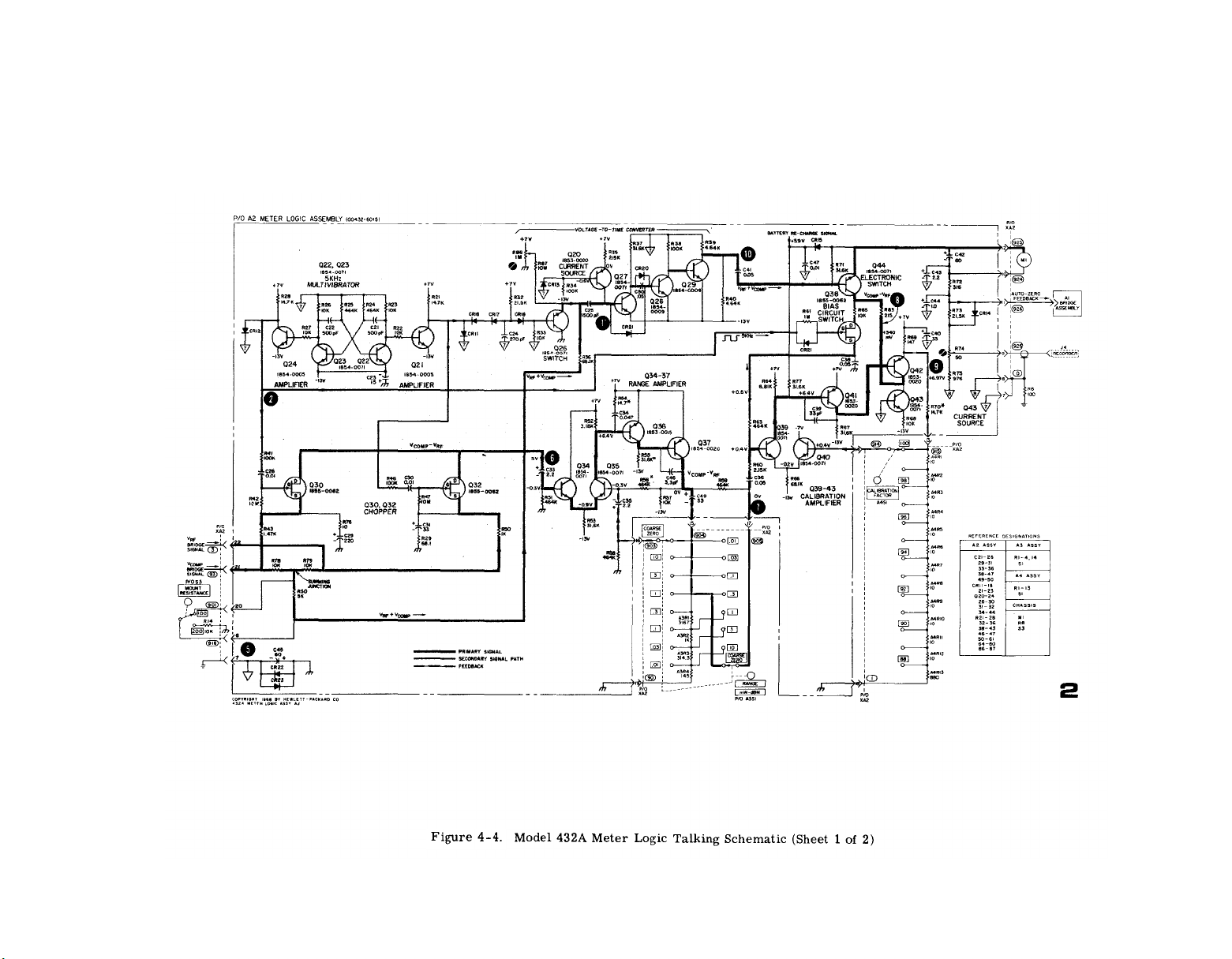
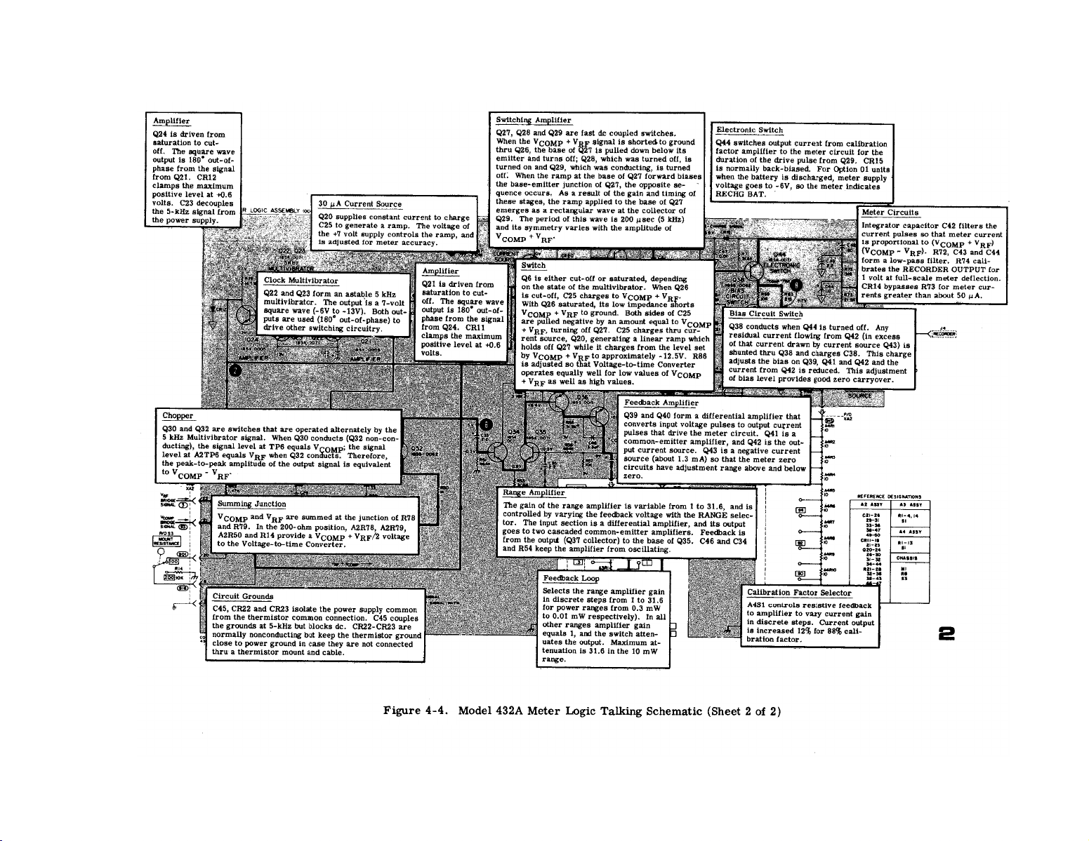
Model 432A Meter Logic Talking
Schematic . . . . . . . . . . . . . . . . . . . . . . . . ...4-6
Model 432A Power Supply Talking
Schematic . . . . . . . . . . . . . . . . . . . . . . . . .4-8
Check and Adjustment Test Setup . . . . . . . . . 5-1
Zero Carryover Test Setup . . . . . . . . . . . . . . 5-3
Bridge Amplifier Test,... . . . . . . . . . . . ...5-10
Transistor Biasing and Operating
Chmacteristics . . . . . . . . . . . . . ...5-12
LIST OF ILLUSTRATIONS
Page
Number
7-1. Servicing Block Diagram . . . . . . . . . . . . 7-3
Model 432A Top Internal View . . . . . . . . . . . 7-4
7-2.
Mode1 432A Waveforms . . . . . . . . . . . . ...7-4
7-3.
Mode1 432A Test Point Locations . . . . . . . . 7-5
7-4.
Model 432A Bottom View,
7-5.
7-6.
7-7.
7-8.
7-9. RF and Compensation Bridge
7-10. Mode1 432A Switches . . . . . . . . . . . . . . ...7-12
7-11. A2 Meter Logic Assembly,
7-12. Meter Logic Schematic Diagram . . . . . . . . . 7-13
7-13. A2 Meter Logic Assembly, Power
7-14. A7 Battery Charging Circuit (Option 0l)
7-15. Power Supply, Schematic Diagram . . . . . .7-l5
7-16. Thermistor Cable Wiring Diagram . . . . . . . 7-16
A1-1. A2 Meter Logic, Component Locations . .. A1-2
A1-2. A2 Meter Logic Assembly, Power
A1-3. Meter Logic Schematic Diagram . . . . . . .. A1-3
Component Locations . . . . . . . . . . . . ...7-6
Mode1 432A Front Panel Interior . . . . . . . 7-6
Al Bridge Assembly,
Component Locations . . . . . . . . . . . . . . . 7-10
Mode1 432A Rear Panel Interior . . . . . . . . . 7-10
Schematic Diagram . . . . . . . . . . . . ...7-11
Component Locations . . . . . . . . . . . . . . 7-13
Supply Component Locations . . . . . . . 7-15
Component Locations . . . . . . . . . . . . 7-15
Supply, Component Locations . . . . . . .A1-2
List of Illustrations
Page
APPENDIX A.
B. BASIC ISSUE ITEMS LIST
C.
D.
MANUAL CHANGES
--------------------------------
-----------------------------
MAINTENANCE ALLOCATION CHART
REPAIR PARTS LIST
-------------------------------
------------------
Al-1
B1-1
C1-1
D1-1
iv
Page 7

GENERAL INFORMATION
1.
Introdution
4.
Incoming Inspection
-------------
------------------
--------
OPERATION ---------------------
7.
Precautions -------------
8.
Mechanical Shock
10.
Biasing Thermistors -----
11.
Minimum Input
13.
Average Power
14.
Pulse Energy and Peale
Power 478A/432
15.
Pulse Energy and Peak
Power 478A/431
19.
Drift Precaution --------
21.
Zero-Set
RF Power Turned Off For
23.
- ---------- -- - - -
---------
--------------
-------- -----
---------
------ --
Zero-Set ---------------
25.
Thermistor Mount Dis-
connected For Zero-
------------------
Set
26.
478A/431
478A/432 ----------------
30.
31.
Mount Calibration Data --
33.
-Calibration Factor ------
35.
Effective Efficiency ----
37.
Calibration Data
Application
39
Thermoelectric Effect ---
.
43.
Thermoelectric Effect
- - - --- - ------ - --
--- - --- - - - -
Error Correction
478A/431
45.
Thermoelectric Error
478A/432
OPERATING PRINCIPLES
-------- ---------
---------------
------- ---
47. Circuit Description -----
52. 431-Power Meter
Detection . . . . . . . . . . . . .
54.
432 Power Detection -----
MAINTENANCE
56. Mechanical Shock
58.
Check On Thermistor
60.
Repair
71.
Thermistor Assembly Re-
-------- -------- ----
Match
---------------------
--------------------
---------
placement Procedure ---
75.
Removal Procedure -------
76.
Installation Procedure --
Page
8-1
8-1
8-2
8-2
8-2
8-2
8-2
8-2
8-2
8-2
8-3
8-3
8-3
8-3
8-4
8-4
8-4
8-5
8-5
8-5
8-5
8-5
8-6
8-5
8-5
8-5
8-6
8-6
8-6
8-6
8-6
8-7
8-8
8-9
8-9
Number Title
1
2
Specifications
Methods of Switching Off
RF Output of Various HP
Signal Generators
3
Parts Furnished in
Thermistor Assembly
Replacement Kit, HP
00478-600------------------
List of ILLUSTRATIONS
Number
1
Maximum Power Meter Read-
ing vs PRF for Pulses
Shorter than 250 u s ----
2
Maximum Power Meter Read-
ings vs Duty Cycle for
Pulses Longer than
250 u s ----------------
3
3 Maximum Power Meter Read-
ing vs Square and Sine
Wave Frequency ----------
4
Source Impedance Shunting
One RF Thermistor
Mount ------ -------------
5
Schematic Diagram of a
Model 478A Thermistor
Mount when Connected to
a 431 Power Meter --------
6
Schematic
Model 478A Thermistor
Mount when Connected to
a 4,82 Power Meter ----
7
Check on Model 478A
Thermistor Resistance
Match
8
9
Thermistor Compensation --Model 478A Thermistor
Mount Assembly ----------
10
HP Model 478A Printed
Circuit A
LIST OF TALBLES
-- - ---------
Diagram of a
------- ------ -
SSy Wiring -----
-------
Page
8-2
8-4
8-8
Page
8-3
8-3
8-3
8-4
8-5
---
8-7
8-7
8-8
8-9
8-10
v
Page 8
Section I
Model 432A
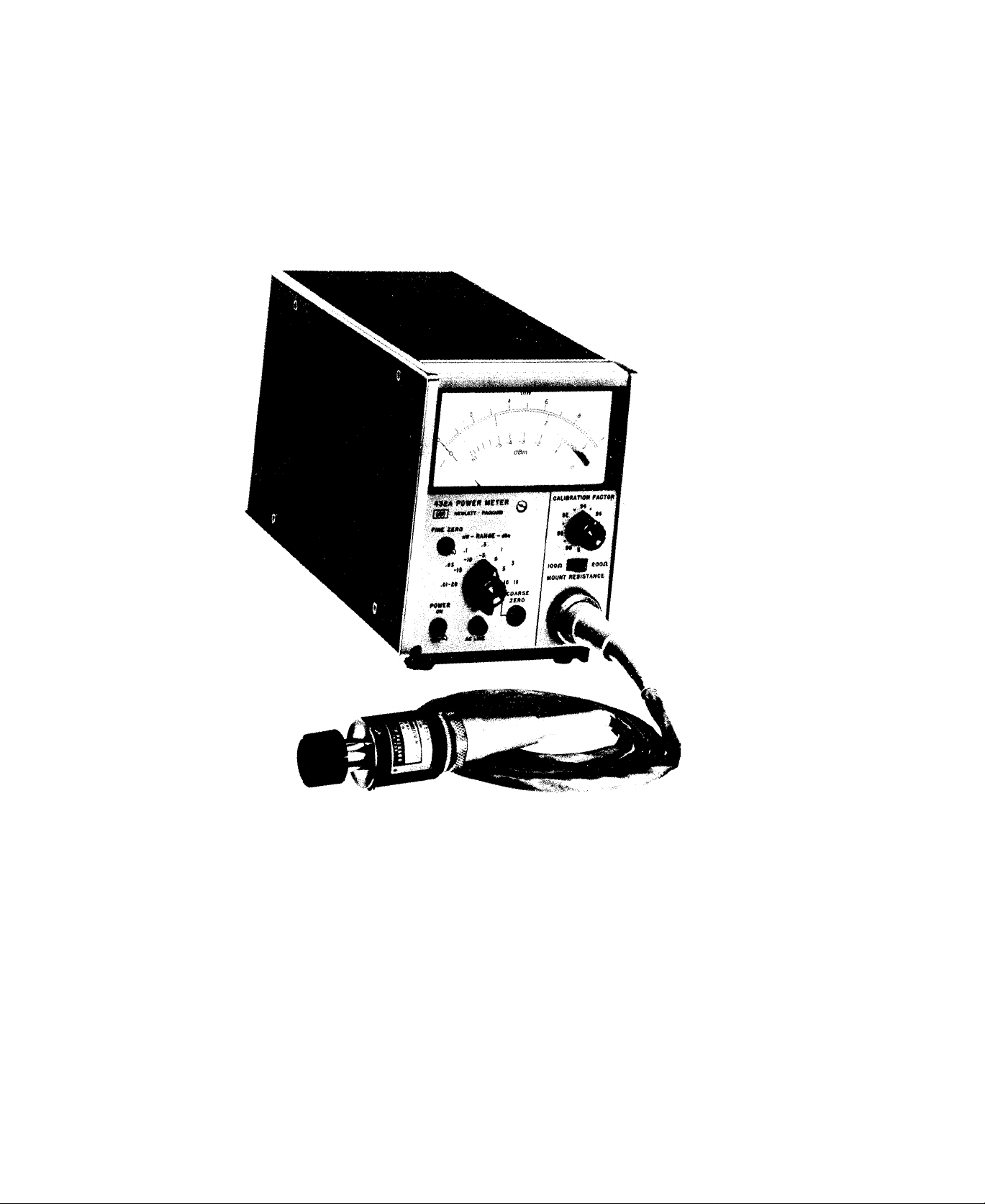
Figure 1-1. HP Model 432A POWER METER
vi
Page 9
Model 432A Section I
SECTION I
GENERAL INFORMATION
1-1. DESCRIPTION.
1-2. The Hewlett-Packard Model 432A Power Meter,
with HPtemperature -compensated thermistor mounts,
measures RF power from 10 microwatt (-20 dBm)
to 10 milliwatts (+10dBm) full scale with 1% of full
scale accuracy from 10 MHz to 40 GHz. With a selector switch, the instrument normalizes the power
meter reading to compensate for the Calibration Factor
of a thermistor mount used for a given measurement.
For portable operation, Option 01 instruments have a
rechargeable nickel-cadmium battery. See Table 1-1
for complete specifications.
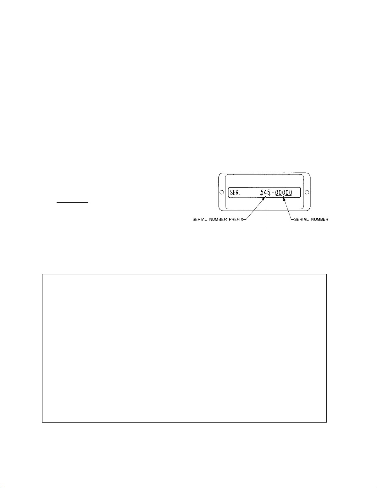
1-5. INSTRUMENT IDENTIFICATION.
1-6. Hewlett-Packard instruments are identified by
an 8-digit serial number. The first three digits are
the Serial Prefix. To properly match a manual with
the instrument to which it applies, the prefix on the
instrument must be the same as the pref ix at the front
of the manual. If the numbers are different, information is supplied either on yellow Manual Change
Supplements, or in an Appendix in the Manual. If the
change information is missing, contact your HP Sales
Office (Sales Offices are listed at the b a c k of the
Manual).
1-3. The Model 432A has provision for dc substitution
measurements and for power meter calibration. An
output is provided for recorders or digital voltmeter
readout.
1-4. Accessories, Two accessories are supplied with
the Model 432A Power Meter: a 7. 5-foot (2290 mm)
detachable power cable and a 5-foot ( 1520 mm) cable
that connects the thermistor mount to the meter. Ther mister mounts are available but not supplied with the
power meter (refer to Table 1-2). Table 1-1 lists
those accessories supplied and also those available. Figure 1-2. Instrument Identification
Table 1-1. Specifications
Instrument Type: Automatic, self -balancing power
Zero Carryover: Less than +0.5% of f u 11 scale
meterforuse with temperature -compensated ther - when zeroed on most sensitive range.
mister mount.
Power Range: 7 ranges with full-scale readings of
Fine Zero: Automatic, operated by toggle switch.
10, 30, 100, and 300 µW, 1, 3 and 10 mW; also
calibrated in dBm from -20 dBm to +10 dBm full
Recorder Output: 1.000 volt into open circuit cor scale in 5-dB steps. responds to full-scale meter deflection (1. O on
O,- 1 scale) +0.5%; 1000-ohm output impedance,
Accuracy:
+55
Calibration Factor Control: 13-position switch nor-
±1% of full scale on all ranges (+O°C, to
o
C).
BNC connector.
RFI: Meets all conditions specified in MIL-I-6181D.
realizes meter reading to account for thermistor
mount Calibration Factor. Power: 115 or 230 Vac ±10%, 50 to 400 Hz, 2-1/2
Range: 100% to 88% in l% steps.
watts. Optional rechargeable battery provides up
to 20 hours continuous operation. Automatic bat-
Thermistor Mount: External temperature -compen - tery recharge.
sated thermistor mounts required for operation
(see Table 1-2).
Weight: Net 6-1/2lb(3kg), shipping 9-1/4lb(4,2kg).
Meter: Taut -band suspension, individually com-
puter-calibrated, mirror-backed scales. Mini - Weight with Optional Battery Pack: Net 9-1/4 lb
watt scale more than 4-1 4 inches (108 mm) long.
(4,2 kg), shipping 12 lb (5,5 kg).
1-1
Page 10

Section I Model 432A
Table 1-1.
1-2
Table 1-2.
Page 11

Model 432A
Section II
Installation
SECTION II
INSTALLATION
2-1. INITIAL INSPECTION.
MECHANICAL CHECK.
2-2.
2-3. If damage to the shipping carton is evident, ask
that the carrier’s agent be present when the instrument
is unpacked. Inspect the instrument for mechanical
damage. Also check the cushioning material for signs
of severe stress.
2-4. PERFORMANCE CHECKS.
2-5. The electrical performance of the Model 432A
should be verified upon receipt. Performance checks
suitable for incoming inspection are given in Section V,
Maintenance.
2-6. DAMAGE CLAIMS.
2-7. If t h e instrument is mechanically damaged in
transit, notify the carrier and the nearest HewlettPackard field off ice immediately. A list of field offices
is at the back of this manual. Retain the shipping carton and padding material for the carrier’s inspection.
The field off ice will arrange for replacement or repair
of your instrument without waiting for claim settlements against the carrier,
2-8. Before shipment this instrument was inspected
and found free of mechanical and electrical defects.
If there is any def iciency, or if electrical performance
is not within specifications, notify your nearest Hewlett -Packard Sales and Service Off ice.
2-9. THREE-CONDUCTOR POWER CABLE.
To protect operating personnel, t h e National
2-10.
Electrical Manufacturers Association (NE MA) recommends that the instrument panel and cab in et be
grounded.
All Hewlett-Packard instruments are
equipped with a three-conductor power cable which,
when plugged into an appropriate receptacle, grounds
the instrument.
The off set pin on the power cable
three-prong connector is the ground wire.
2-11. To preserve the protection feature when oper-
ating the instrument from a two-connector outlet, use
a three-prong to two-prong adapter and connect the
green pigtail on the adapter to ground.
2-12. PRIMARY POWER REQUIREMENTS.
The Model 432A operates from 115 or 230 volts
2-13.
ac line voltage.
Line frequency may vary from 50 to
400 Hz. A slide switch on the rear panel is moved to
the correct position for the I in e voltage available.
Before operating the equipment, ensure that the fuse
installed in the instrument corresponds to the value
marked on the panel for the line voltage available ( 1/8
amp slow-blow).
2-14. INTERNAL BATTERY OPERATION.
Model 432A Option 01 instruments contain an
2-15.
internal battery and a battery charging assembly. By
connecting the 432A to an ac source, the battery may
be charged overnight. The battery can be maintained
in the charging state indefinitely without damage. It
will assume its full capacity, 1.25 ampere -hours, and
will not charge in excess of that. This enables the
instrument to operate for approximately 20 hours continuously without recharging.
2-16. BATTERY INSTALLATION.
a. Set power switch to off and remove power plug
from rear panel,
b. Remove top and bottom, and s i d e instrument
covers.
c. The battery is installed with the terminals toward
the right hand side of the instrument when faced from
the front. The two terminals on the battery fit into
spaces provided on the circuit board.
d. Using the retaining nuts, fasten the battery firmly
in place. Be careful not to short the battery terminals
at any time as this may cause battery cell damage.
e. Install Assembly A7, battery charging board, in
the space provided for it just ahead of the battery.
f. Reinstall instrument covers and adjust circuit.
Instrument is now ready for operation.
2-17. BATTERY STORAGE.
2-18. Store the battery at or below room temperature.
Extended storage at high temperature will reduce the
cell charge, but will not damage the battery if t h e
storage temperature is below 140” F. Install the battery in the instrument and recharge before using
Model 432A in battery operation.
2-19. RACK MOUNTING.
Model 432A is narrower than full-rack width.
2-20.
It is what is termed a sub-modular unit. When used
alone, the instrument can be bench mounted. When
used in combination with other sub-modular units it
may be bench or rack mounted. The HP 1051A and
1052A Combining Cases and Rack Adapter Frames are
designed specifically for this purpose.
2-21. COMBINING CASE.
2-22. A model 1051A Combining Case is shown in
Figure 2-1. This case is full rack width and accepts
varying combinations of submodular instruments. The
case, purchased separately, is provided with a rack
mount ing kit.
The combining case will hold three
2-1
Page 12
Section II
Installation
Model 432A
instruments the same size as the Model 432A. When
instruments are installed in the combining case, they
may be installed or removed individually.
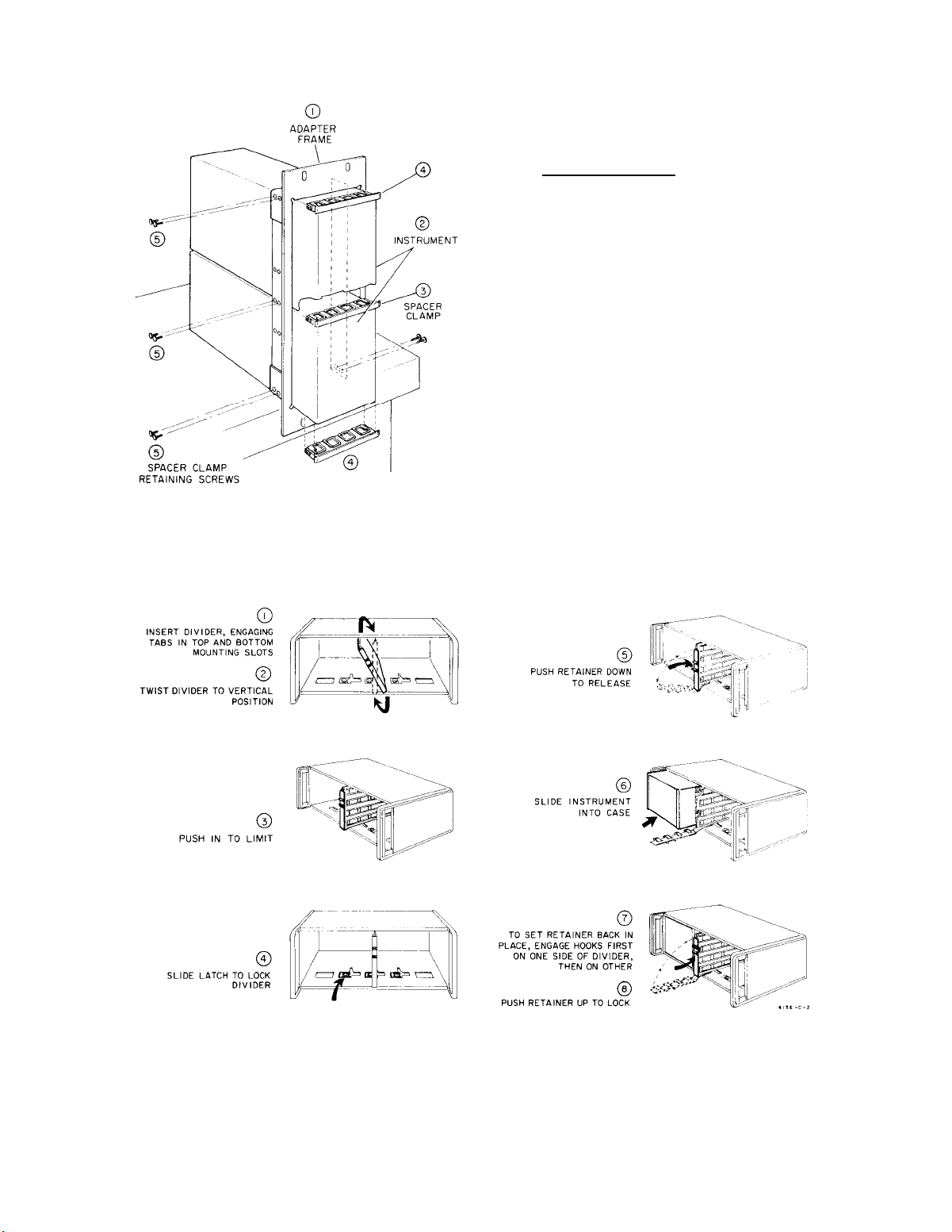
2-23. ADAPTER FRAMES.
2-24. The 5060-0797 Adapter Frame is shown in Figure 2-2. The frame will accept a variety of submod ular units in a manner suitable for rack mounting.
Submodular units, in combination with anv necessarv
spacers are assembled within the frame.
A submod-
ular unit cannot be removed individually.
2-25. REPACKING FOR SHIPMENT.
Figure 2-1.
Sub -module Installation in
Rack Adapter Frame
2-26. When returning an instrument
Packard use the original packing material.
to HewlettIf the orig -
inal foam type packing material is not available, contact an authorized HP Sales Office for assistance. If
this is not possible, first protect the instrument surfaces by wrapping in heavy kraft paper or with sheets
of cardboard flat against the instrument, Protect the
instrument on all s i d e s using approximately 4“ of
packing material and pack in a durable container. Mark
the container clearly for proper handling and insure
adequately before shipping.
2-27. When an instrument is returned to HP for ser-
vice or repair, attach atagtothe instrument specifying
the owner and desired action. All correspondence
should identify the instrument by model number and
full eight -digit serial number.
2-2
Figure 2-2. HP Model 1051A Combining Case Instrument Installation
Page 13

Model 432A
Operating Instructions
Section III
SECTION Ill
OPERATING INFORMATION
3-1. INTRODUCTION.
3-2. The Model 432A Power Meter operates with HP
temperature-compensated thermistor mounts such as
the 8478B and 478A Coaxial, and 486A Waveguide
series. The frequency range of the 432A with these
mounts in 50-ohm coaxial systems is 10 MHz to 18 GHz;
in waveguide systems it is 2.6 GHz to 40 GHz. Fullscale power ranges are 10 microwatts to 10milliwatts
(-20 dBm to +10dBm). Extended measurements may
be made to 1 microwatt (-30 dBm). The total meas-
urement capacity of the instrument is divided into
seven ranges, selected by a f rent-panel RANGE switch.
3-3. This section describes general operating pro-
cedures and error analysis in microwave power messurement. Application Note 64, available on request
from Hewlett-Packard, is a detailed analysis of microwave power measurement problems and techniques.
3-4. CONTROLS, CONNECTORS, AND
INDICATORS.
3-5. The front and rear panel controls, connectors,
and indicators are explained in Figure 3-2. The des-
c riptions are keyed to the corresponding items which
are indicated on the figure.
3-6, The COARSE ZERO and FINE ZERO controls
zero the meter. Zero carry-over from the most sen-
sitive range to the other six ranges is within ± 0.5%.
When the RANGE switch is set to COARSE ZERO, the
meter indicates thermistor bridge unbalance, and the
front panel COARSE ZERO adjust is for initial bridge
balance. For best results, FINE ZERO the 432A on
the particular meter range in use.
3-7. The CALIBRATION FACTOR switch provides
discrete amounts of compensation for measurement
uncertainties related to SWR and thermistor mount
efficiency. The Calibration Factor value permits direct meter reading of the RF power delivered to an
impedance equal to the characteristic impedance (Z
of the transmission line between the thermistor mount
and the RF source. Calibration Factor values a r e
marked on the label of each 8478B, 478A, or 486A
Thermistor Mount.
For further details, see Para-
graph 3-23.
3-8. The MOUNT RESISTANCE switch on the front
panel compensates f o r t h r e e types of thermistor
mounts. Model 486A waveguide mounts can be used
by setting the MOUNT RESISTANCE switch to
100Ω
or 200Ω, depending on the thermistor mount used
(refer to Table 1-2). The
200Ω position is used with
Models 478A and 8478B Thermistor Mounts.
3-9. The rear-panel BNC connector lab e 1 ed RE-
CORDER provides an output voltage linearly propor tional to the meter current; 1 volt into an open cir-
cuit equals full- scale meter deflection. This voltage
is developed across a lK resistor; therefore, when
a recorder with a lK input impedance is connected to
the RECORDER output, approximately .5 volts will
equal full scale deflection. This loading of the RE-
CORDER output has no effect on the accuracy of the
432A panel meter.
3-10. A digital voltmeter can be connected to the rearpanel RECORDER output for more resolution of power
meter readings. When a voltmeter with input impedance greater than 1 megohm is connected to the RE-
CORDER output, 1 volt equals full scale deflection.
3-11. The 432A has two calibration jacks (V
vcomp) on the rear panel that can be used for precision power measurements.
Instrument error can
be reduced from ±1% ±(0.2% of reading +5µW) of
reading, depending on the care taken in measure-
and on the accuracy of auxiliary equipment.
ment,
For further information, see Paragraph 3-27.
3-12. BATTERY OPERATION,
3-13. The Model 432A Option 01 operates from battery
and conventional 115- or 230-volt line power. A rechargeable Nickel-Cadmium b a t t e r y is factoryinstalled in Option 01 instruments. The same battery
can be ordered and later installed in the basic instrument, thereby modifying the power meter to the Option
01 configuration. The battery installation kit (including
battery charging circuit ) may be ordered from the
nearest HP Sales Office.
3-14. It is recommended that the Model 432A be bat-
tery -operated for up to 8 hours, and then allowed to
recharge 8 hours, or overnight. Continuous battery
operation is possible for up to about 24 hours, but then
)
o
the battery must be recharged f o r about 24 hours.
3-15. The 432A automatically operates on its internal
batteries whenever the ac line power is disconnected
and the POWER switch is ON. When the battery ter-
minal voltage decreases far enough to f orce the power
supply voltage regulator out of regulation, then the
meter stops working and the meter indicator points to
the red RECHG BAT. To recharge the battery, simply
connect the 432A to ac line power, and turn it ON.
3-16. Battery Storage. Storage of the battery at or
below room temperature is best, Extended storage
at temperatures above room temperature will reduce
cell charge, but will not damage the battery; however,
the battery should not be stored where the tempera-
ture exceeds 60” C (+140° F).
RF and
3-1
Page 14
Section III
Operating Instructions
Model 432A
3-17. MICROWAVE POWER MEASUREMENT
ACCURACY.
3-18. A number of factors affect the overall accuracy
of power measurement.
The major sources of error
are mismatch error, RF losses, and instrumentation
error.
3-19. Mismatch Error.
In a practical measurement
situation, both the source and thermistor mount have
SWR, and the source is seldom matched to the ther mister mount unless a tuner is used. The amount of
mismatch loss in any measurement depends on the total
SWR present.
The impedance that the source sees is
determined by the acutal thermistor mount impedance,
the electrical length of the line, and the characteristic
impedance of the line, Z
.
o
3-20. In general, neither the source nor the thermistor mount has Z
are known only as reflection coefficients, mismatch
impedance, and the actual impedances
O
losses, or SWR. The power delivered to the thermis-
tor mount - and hence the mismatch loss - can only be
described as being somewhere between t w o limits.
The uncertainty of power measurement due to mismatch
loss increases with SWR. Limits of mismatch loss
are generally determined by means of a chart such as
the Mismatch Loss Limits charts in Application Note
64. The total mismatch 1 oss uncertainty in power
measurement is determined by algebraically adding
the thermistor mount losses to the uncertainty caused
by source and thermistor mount 2
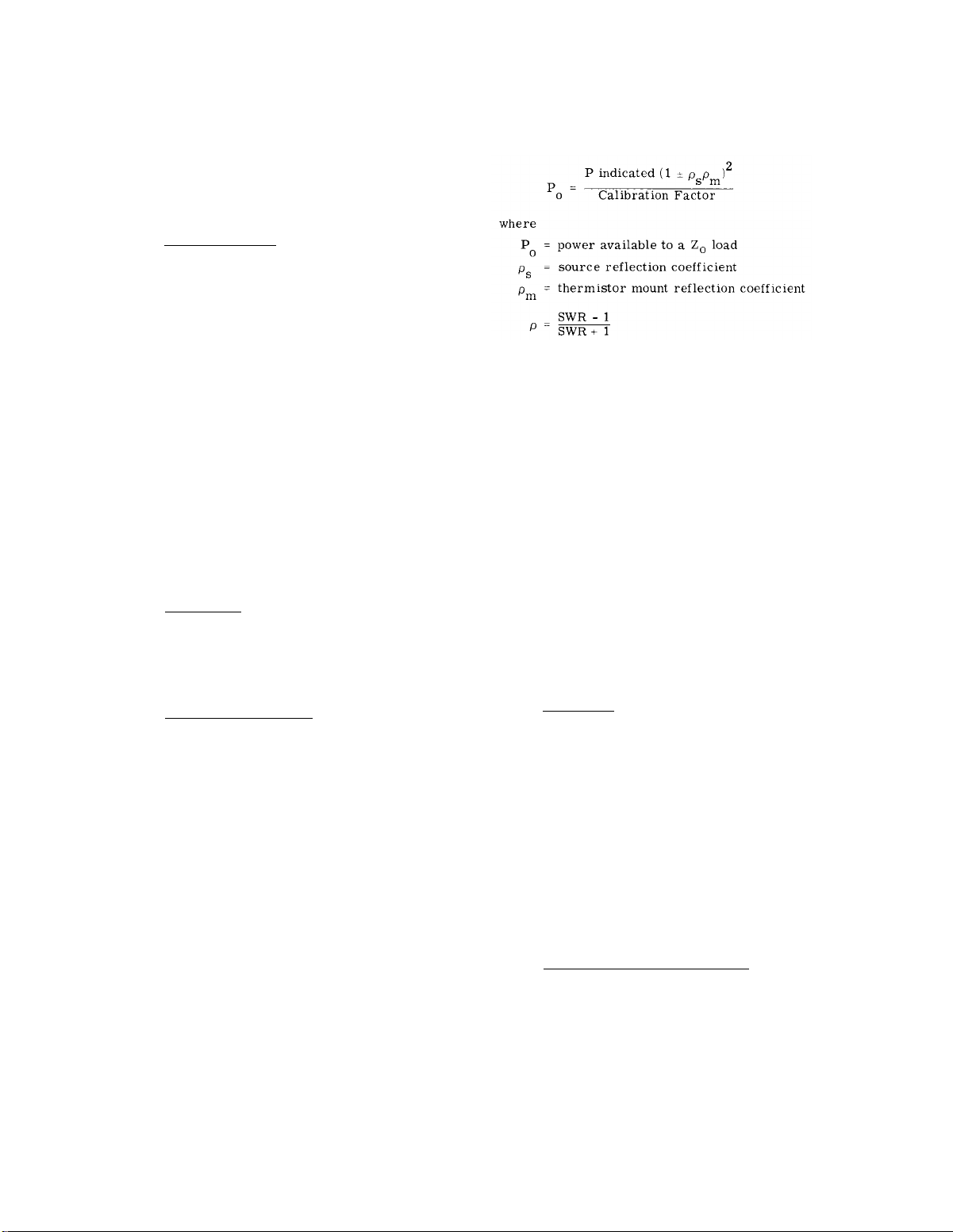
3-21. RF Losses.
RF losses account for the power
match.
0
entering the thermistor mount but not dissipated in the
detection thermistor element.
Such losses may be in
the walls of a waveguide mount, the center conductor
of a coaxial mount, capacitor dielectric, poor connections within the mount, or due to radiation.
a load impedance equal to Z
relationship between indicated power and the power
, More accurately, the
o
available to a Z. load is given by the following equation:
Calibration factor d o e s not compensate for source
VSWR, or for multiple reflections between the source
and the thermistor mount.
3-26. To minimize mismatch between the source and
the thermistor mount without a tuner, insert a low
SWR precision attenuator in the transmission line between the thermistor mount and the source. Since the
mount impedance (and corresponding SWR) deviates
significnatly only at the high and low ends of a microwave band, it is generally unnecessary to use a tuner.
A tuner or other effective means of reducing mismatch
error is recommended when the source SWR is high
or when more accuracy is required. For further details, there is a complete discussion of microwave
power measurement with emphasis on modern techniques, accuracy considerations and sources of error
available in Application Note 64.
3-27. PRECISION POWER
MEASUREMENT.
3-22. Instrumentation Error. The degree of inability
of the instrument to measure the substitution power
supplied to the thermistor mount is called power meter
accuracy or instrumentation error. Instrumentation
error of the Model 432A is ±1% of full scale, O“C to
+55°c.
3-23. CALIBRATION FACTOR AND EFFECTIVE
EFFICIENCY.
3-24. Calibration factor and effective efficiency are
correction factors for improving power measurement
accuracy. Both factors are marked on every HP ther -
mister mount. Calibration factor compensates f o r
thermistor mount VSWR and RF losses whenever the
thermistor mount is connected to an RF source without
a tuner. Effective efficiency compensates for ther -
mister mount RF losses when a tuner is used in the
measurement system.
3-25. When the 432A CALIBRATION FACTOR selec tor is set to the appropriate factor indicated on the
thermistor mount, the power indicated by the meter
is the power that would be delivered by the source to
3-2
3-28. GENERAL.
3-29. Using precision instruments and careful procedures, measurement error can be reduced to ±0.2%
of reading +0.5 µW. The technique involves: 1) zero-
ing the bridge circuits and measuring the bridge amplifier output voltage difference with a digital voltmeter, then 2) connecting RF power to the thermistor
mount and then measuring the bridge amplifier output
voltage difference again, and 3) calculating the power
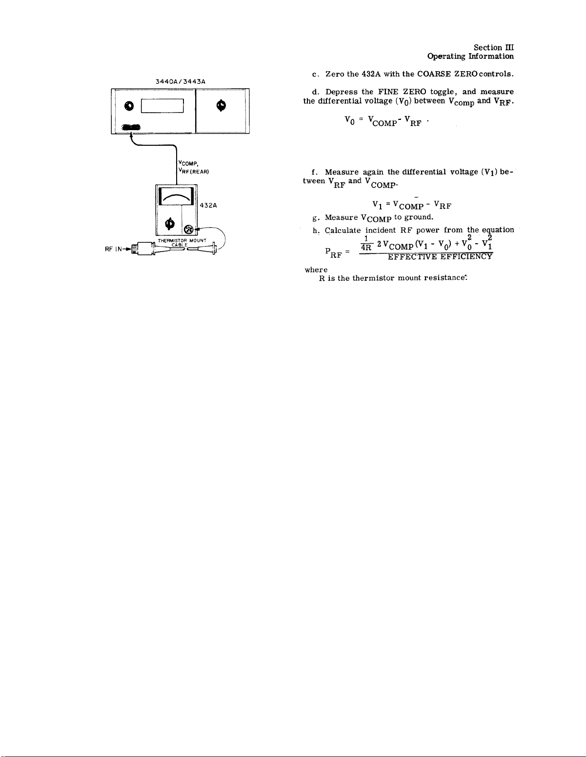
from ‘the two measurements. Figure 3-1 shows the
instrument setup for dc substitution measurement.
Use an HP Model 3440A DVM, with a 3443A Plug-in
Unit or a digital voltmeter with equivalent accuracy,
3-30. MEASUREMENT PROCEDURE.
a. Connect the DVM to the 432A rear panel Vcomp
and V
RF outputs.
Be sure that the digital voltmeter
input is isolated from chasses ground,
b. Turn off, or disconnect the RF power from the
thermistor mount.
Page 15
Model 432A
Section III
e. Release the FINE ZERO toggle, and turn on, or
reconnect the RF power to the thermistor ,mount.
Figure 3-1.
Precision Power Measurements
3-3
Page 16
Section III
General Information
Model 432A
3-4
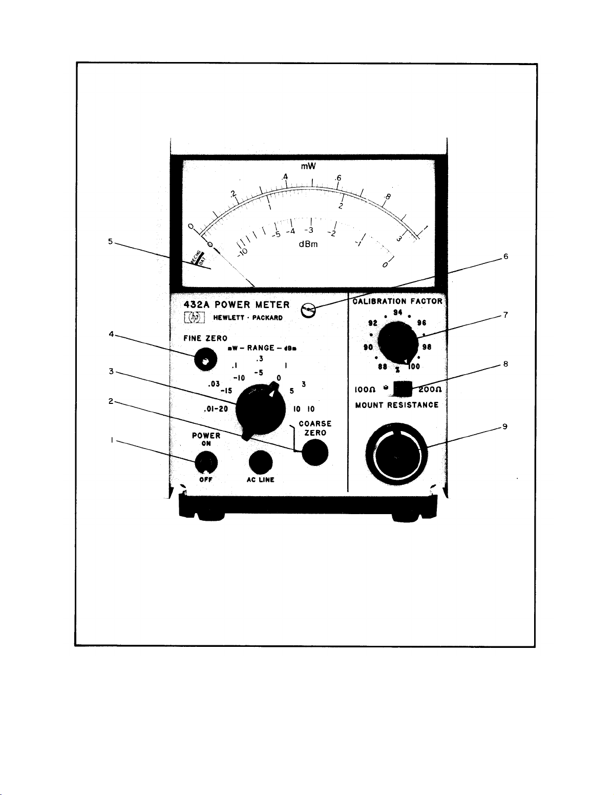
Figure 3-2. Front Panel Controls, Connectors and Indicators (Sheet 1 of 2)
Page 17

Model 432A
Operating Information
Section III
1.
POWER. Instrument power ON/OFF switch;
connects either ac line voltage or internal bat- sion so that meter indicates zero. To adjust
tery (Option 01 only) to internal voltage regu - the zero:
later circuits. When ac power is on, optional
battery charging circuit operates.
2.
COARSE ZERO. Meter zero adjustment; set the indicator falls below zero and comes
the RANGE selector to COARSE ZERO, turn back up to zero again.
OFF the RF power, and adjust to zero the meter.
3.
RANGE. Power measurement range selector;
selects ranges from 0.01 to 10 milliwatts (-20
to +10dBm). COARSE ZERO setting is used
to zero meter with no power applied to ther -
mistor mount.
4. FINE ZERO. Electronic zero that balances
the compensation bridge with zero RF input.
To zero m e t e r during operation, close the
switch momentarily.
is not applied to the thermistor mount when the
FINE ZERO switch is depressed.
5.
Meter.
mount in milliwatts and dBm. To use the dBm
scale, note the value in dBm of the range in
use, and subtract from it the reading on the nectorfor 5-1/2 foot cable that connects to the
meter dBm scale.
Indicates power input to thermistor meter.
Be sure that RF power
6. Mechanical Meter Zero. Sets meter suspen-
a. Turn POWER switch off.
b. Turn the adjustment screw clockwise until
c. Turn the adjustment very slightly counter-
clockwise to free up tbe mechanism from
the adjusting peg.
CALIBRATION FACTOR. Amplifier gain com-
7.
pensation selector. Set to correspond to the
calibration factor printed on t h e thermistor
mount body. See Paragraph 3-23 for m o r e
information.
8.
MOUNT RESISTANCE. Se1ects resistance
equal to that of mount in use to balance bridges.
Table 1-2 lists Hewlett-Packard thermistor
mounts and resistances. Set with meter power
OFF, when mount is initially connected to the
9.
Thermistor Mount Cable Connector. Input con478A, 8478B, or 486A Thermistor Mounts.
Figure 3-2. Front Panel Controls, Connectors and Indicators (Sheet 2 of 2)
3-5
Page 18
Section III
Operating Information
Model 432A
3-6
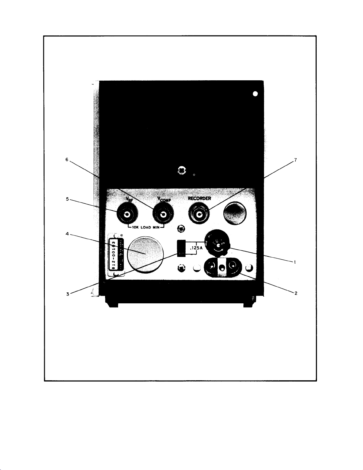
Figure 3-3. Rear Panel Controls and Connectors (Sheet 1 of 2)
Page 19

Model 432A
Operating Information
Section III
1,
Line Fuse. For 115 Vac or for 230 Vac use
1/8 amp slow-blow fuse.
2. Power Cord Input. Use power cord provided,
HP 8120 -00?8. Line power limits are 115/230
Vat, 50-400 Hz. Check FUSE rating and
PO-
sition of line voltage slide switch before connetting power.
Line Voltage Slide Switch: Set to line voltage
3.
avallable (115 or 230 Vat, 50-400 Hz).
4.
Mounting Hole for Option 02 Model Power
Meters.
Thermistor mount cable connector meter. Output impedance is approx.
installed and wired in parallel with f rent-panel
connector. Only one mount at a time may be
used with the power meter.
VRF Input. Connected directly to RF bridge.
5.
Used for calibrating power meter with HP 8477A
Power Meter Calibrator. Also used for precision power measurements.
VCOMP Input. Connected directly to compen-
6.
sation bridge. Used for calibrating power meter
with HP 8477A Power Meter Calibrator. Also
used for precision power measurements.
RECORDER OUTPUT. Voltage f r o m meter
7.
circuit to be used for recorder or digital volt-
1000Ω.
Figure 3-3. Rear Panel Controls and Connectors (Sheet 2 of 2)
3-7
Page 20

Section III
Operating Information
Model 432A
3-8
Figure 3-4. Turn On and Zeroing Procedure (Sheet 1 of 2)
Page 21

Model 432A
Operating Information
1. Connect the thermistor mount and cable to 5. Set the RANGE selector to COARSE ZERO and
THERMISTOR MOUNT connector. Refer to then zero the meter with the COARSE ZERO
Table 1-2 for recommended thermistor mounts screwdriver adjustment.
and their frequency ranges.
Note
2.
Meter Mechanical Zero:
a. With the instrument turned off, rotate the
meter adjustment screw clockwise until the
pointer approaches the zero mark from the
left.
b. Continue the clockwise rotation until the
The power meter should be zeroed with the
RF power source turned off, or the mount
disconnected from the source.
6. Set the range selector to the 0.01 mW range;
then depress the FINE ZERO switch until the
meter indicates zero.
pointer coincides with the zero mark. If
the pointer overshoots, continue rotating
the adjustment screw clockwise until the
pointer once again approaches the zero mark
Range-to-range zero carryover is 1 ess
Note
from the left. than ±0.5% if the meter zero has been ad-
C. Rotate the adjustment screw about three de-
grees counterclockwise to disengage screw
adjustment from the meter suspension.
justed (step 2 above), and the instrument
has been properly zero-set on the sensi -
tive range. For maximum accuracy, zero-
set the power meter on the range to be
used.
3.
Set the MOUNT RES switch to correspond to
the operating resistance of thermistor mount
used.
4,
Turn the 432A POWER switch ON. For battery
operation, the AC LINE indicator does not turn
on.
Set CALIB FACTOR switch to correspond to
7.
Calibration Factor imprinted on HP thermistor
mount label.
8.
Apply RF power to the thermistor mount. Power
is indicated on the meter directly in mW or dBm.
Section III
Figure 3-4. Turn On and Zeroing Procedure
3-9
Page 22
4-0
Section IV
Principles of Operation
Figure 4-1.
Model 432A
Page 23
Model 432A
Principles of Operation
Section IV
SECTION IV
PRINCIPLES OF OPERATION
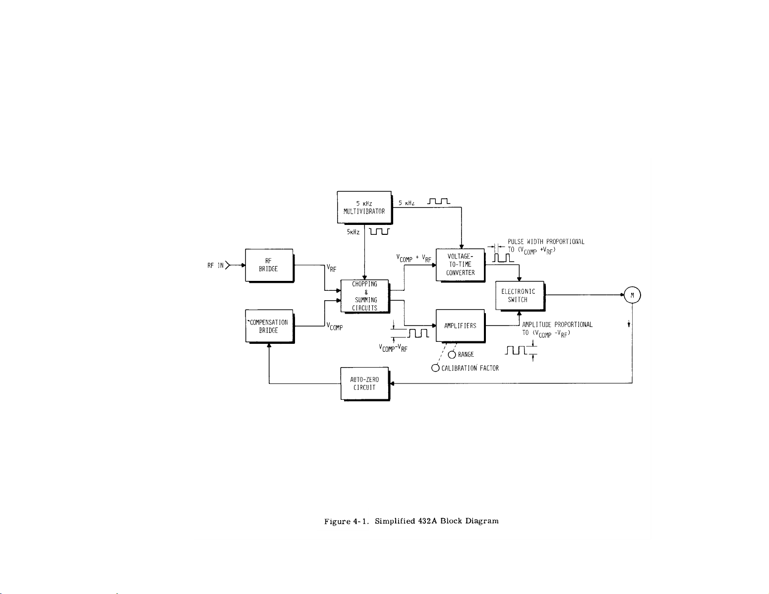
4-1. SIMPLIFIED DESCRIPTION
4-2. The HP 432A Power Meter consists of two major
sections:
the bridge and meter logic assemblies, The
instrument also contains an auto zero circuit which
provides for automatic zeroing on any range. A simplified Mock diagram of the HP 432A is shown in
Figure 4-1.
4-3. The bridge section contains circuits which form
two self-balancing bridge circuits when a suitable
thermistor mount is connected to the 432A. Each
bridge is automatically brought to balance by the
action of a high gain dc amplifier feeding power to the
top of the bridge, The voltage at the top of the RF
bridge V
RF is responsive to both input RF power and
ambient temperature changes.. The voltage at the top
of the compensation bridge, V
only to ambient temperature changes. Knowing V
COMP is responsive
RF
and VCOMP, the RFpower can be calculated.
4-4. The meter logic section processes V
V
COMP to produce a meter current proportional to
RF power. The sum (V
RF + VCOMP) controls the
width of 5 kHz pulses. The difference (V
RF and
COMP - VRF)
is chopped, amplified and fed to an electronic switch
actuated by the controlled width pulses. Therefore,
the meter current is pulses of variable height and
width with the meter indicating the average current.
(This process produces a meter current proportional
to (V
RF + VCOMP) (VRF - VCOMP ). Paragraph 4-10
explains why this is necessary.
4-8. If ambient temperature causes changes in the
thermistor resistance, the bridge circuits respond by
applying an error voltage to the bridges to maintain
bridge balance.
The voltage at the top of the RF
bridge is dependent upon both ambient temperature
and the RF input. The voltage at the top of the compensation bridge is dependent upon the ambient temperature only. The power meter reading is brought to
zero with no applied RF power by making V
COMP
equal to VRF so (VCOMP - VRF) equals zero. Since
ambient temperature causes both thermistors to respond similarly, there will be no net difference between the amplifier output voltages. Therefore, any
difference in output voltages from the bridges is now
due to RF power absorbed by the thermistor mount.
4-9. The RF bridge voltage, V
tion bridge voltage, V
COMP, contain the “RF power”
RF, and the compensa-
information. To provide a meter reading proportional
to RF power the dc voltages (V
RF, VCOMP) must be
further processed by the meter logic circuits.
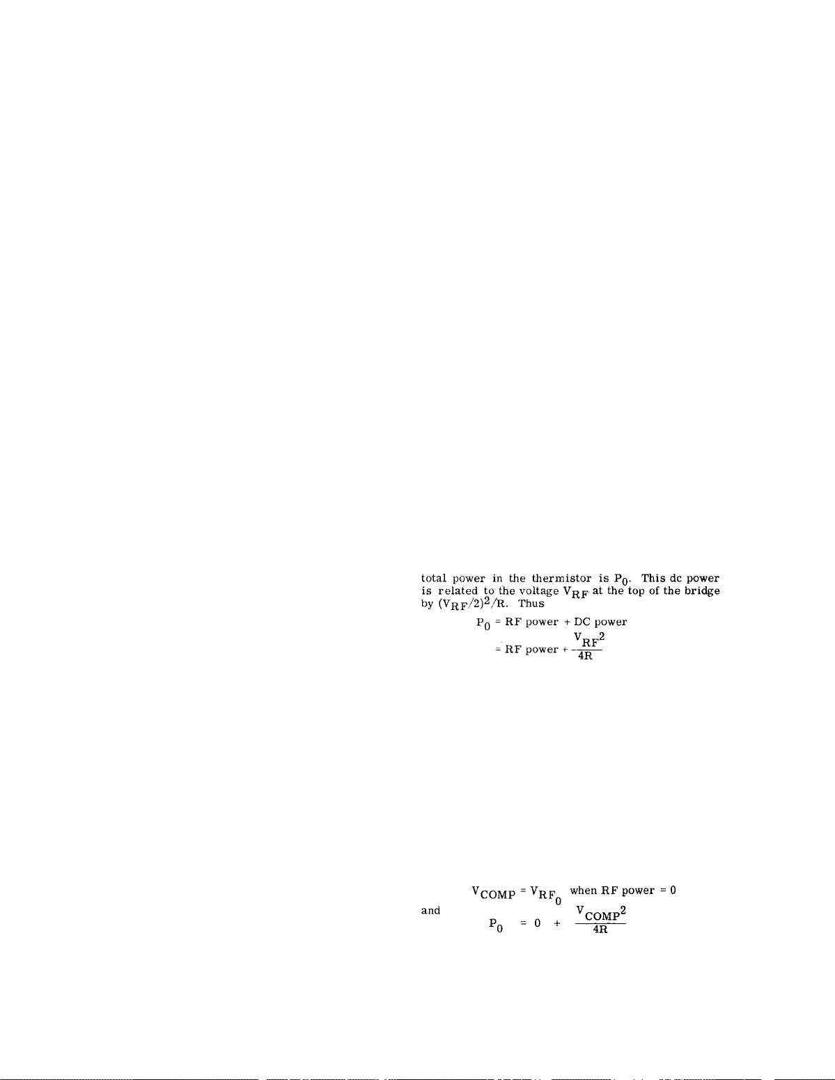
4-10. The required processing is derived as follows:
P. is absorbed power needed by the RF thermistor
to bring its resistance to R ohms (100 or 200 ohms).
P. consists of two components: RF power from the
signal source to be measured and dc power supplied
by the 432A. The self balancing action of the bridge
circuit automatically adjusts the dc power so that the
4-5. FUNCTIONAL BLOCK DIAGRAM
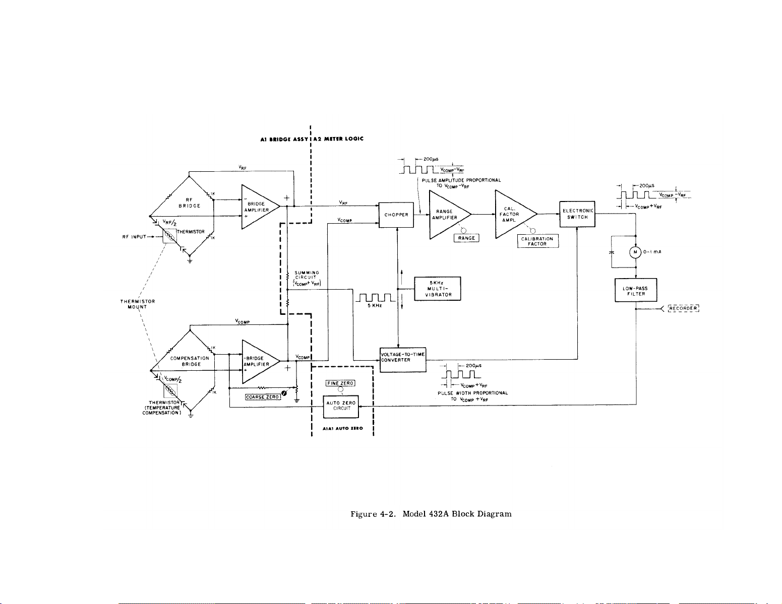
4-6. A functional block of the 432A power meter is
shown in Figure 4-2. The instrument comprises two
major assemblies: bridge assembly Al and meter
logic assembly A2.
Auto zero circuit Al Al, which
provides for automatic zeroing of the instruemtn, is
included as part of logic assembly Al.
4-7. The thermistor bridges are biased with direct
current from the bridge amplifiers.
Each bridge
amplifier supplies enough heating current to br ing the
thermistor resistance to 100 or 200 ohms, depending
upon the setting of the MOUNT RESISTANCE switch
on the 432A. If one of the thermistor bridges is unbalanced due to incorrect thermistor resistance, an
error voltage occurs and is amplified by the bridge
amplifier. The error voltage is applied to the top of
the bridge and changes the power dissipation of the
negative temperature coefficient thermistor.
The
change of power dissipation causes the resistance to
the thermistor to change in the direction required to
balance the bridge. Application of RF power to the
RF bridge heats the thermistor and lowers its resis-
tance. The bridge circuit responds by reducing the
dc voltage applied to the top of the bridge thus main-
taining bridge balance.
4-11. RFpower can redetermined by measuring VRF
with and without applied RF power and then doing
some arithmetic. But this power measuring scheme
is neither convenient nor temperature compensated
(since P. changes with temperature). The 432A introduces another thermistor bridge circuit exposed
to the same ambient temperature but not RF power.
This circuit includes adjustments (COARSE and FINE
ZERO) so that the dc voltage V
bridge can be set equal to V
RF and compensation thermistors, V
power) and V
erature fluctuation.
COMP remain equal with ambient temp-
They cliff er only when the RF
COMP at the top of its
RF. Assuming matched
RF
(with no RF
O
power to be measured is applied to the RF thermistor.
Thus, we have
4-1
Page 24

Section IV
Principles of Operation
Combining equations, we have
4-12. Thus an RF power measurement reduces to
setting V
COMP = V RF
measuring V
COMP and VRF, and computing with the
(with zero RF power) initially,
O
above formula. The 432A carries out the computation
by forming the indicated sum and difference, perform-
ing the multiplication and displaying the result on a
meter.
4-13. The meter logic circuits change the two dc
voltages to two pulse signals which contain all the RF
power information. One of the signals will be a square
wave whose amplitude is proportional to V
RF. The other signal will have a pulse width pro-
V
portional to V
4-14. The V
-
COMP
= VRF .
COMP-VRF signal is obtained by taking
COMP -
the dc voltage outputs from the Al assembly and applying them to a chopper circuit. This chopper cir-
cuit is driven by a 5-kHz multivibrator. The output
of the chopper is a square wave signal whose amplitude is proportional to V
COMP - VRF. The output of
the chopper is coupled to the range amplifier and then
to the calibration factor amplifier. The amplification
that the signal receives in these two amplifiers depends upon the setting of the RANGE switch and the
CALIBRATION FACTOR switch.
The output of the
calibration factor amplifier is V. This current is fed
to the electronic switch. A square wave current with
amplitude proportional to (V
COMP - VRF).
Model 432A
4-15. The V
COMP + VRF signal is obtained by taking
the two dc voltages from Al assembly through a summing circuit and feeding this voltage to a voltage-totime converter.
The voltage-to-time converter is
driven by a 5-kHz multivibrator. The output of the
voltage-to-time converter is a signal whose pulse
width is proportional to the sum of V
COMP + VRF.
This signal controls the electronic switch. From the
COMP - VRF and V COMP + VRF inputs, the elec-
V
tronic switch provides a 5-kHz pulse train whose amp-
litude is proportional to V
width is proportional to V
COMP-VRF and whose pulse
COMP + VRF. The pulse
width is always 90 msec or less.
4-16. The bias circuit switch and filter provides a
zero current reference for the meter circuit. This is
accomplished by controlling the dc bias to the first
stage of the calibration factor amplifier. This circuit,
in effect, restores the dc component to the square wave
which has been amplified by ac coupled amplifiers.
4-17. The meter is 0-1 mA, full-scale meter that
has a capacitor across its terminals. The capacitor
integrates the output pulses from the current switch
so the current into the meter is proportional to the
time average of the input pulses. That is, the input
current to the meter is proportional to the product of
4-18. The output from the meter is further filtered so
the voltage at the rear panel RECORDER output is
suitable for use with either a digital voltmeter or X-Y
recorder. The RECORDER output voltage is returned
to the compensation bridge through the automatic zero
circuit when the FINE ZERO switch is depressed.
The automatic zero circuit holds a correction voltage
at the input of the compensation bridge amplifier, so
when the RF is zero, the meter indication will also
be zero.
4-2
Page 25
Model 432A
4-3
Principles of Operation
Section IV
Figure 4-2.
Page 26
4-4
Section IV
Principles of Operation
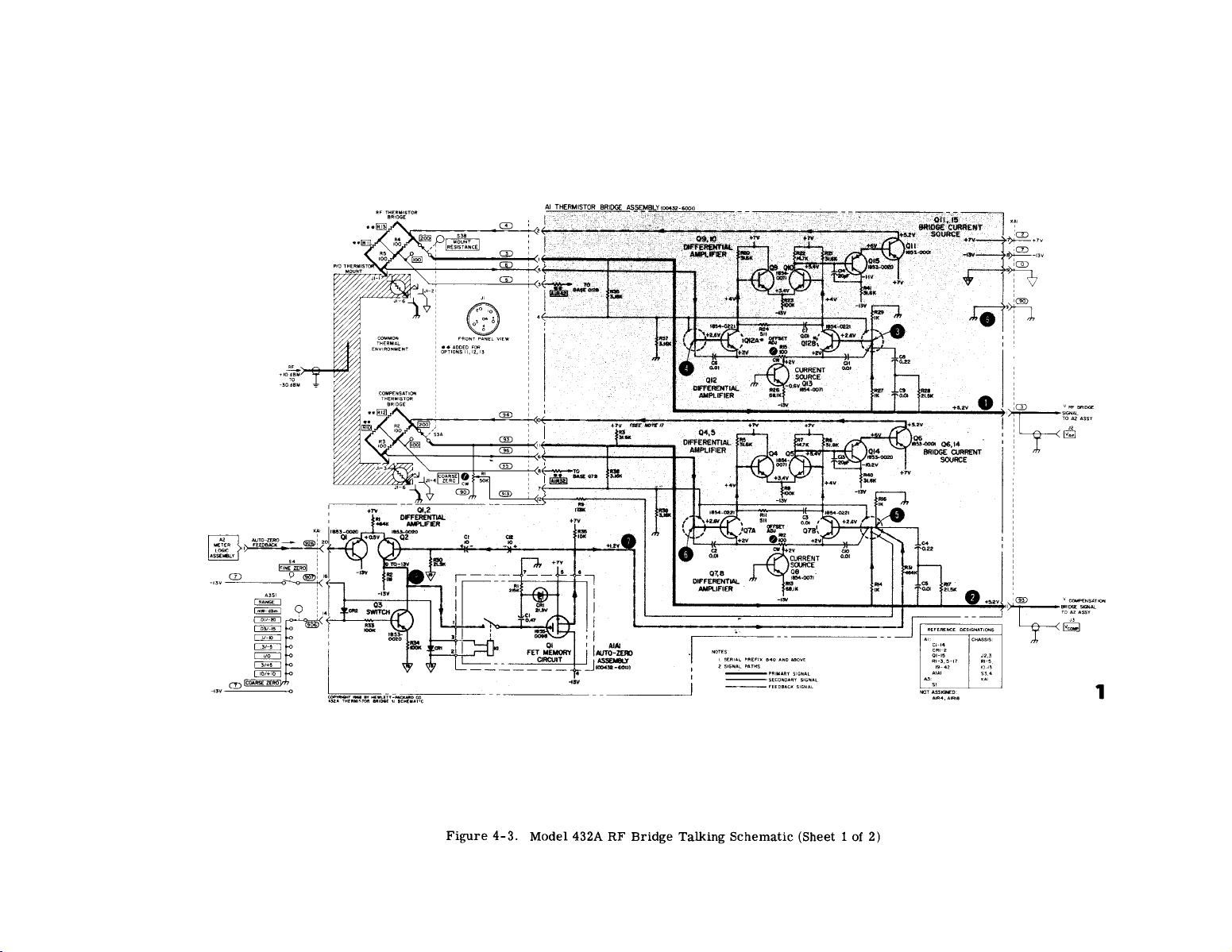
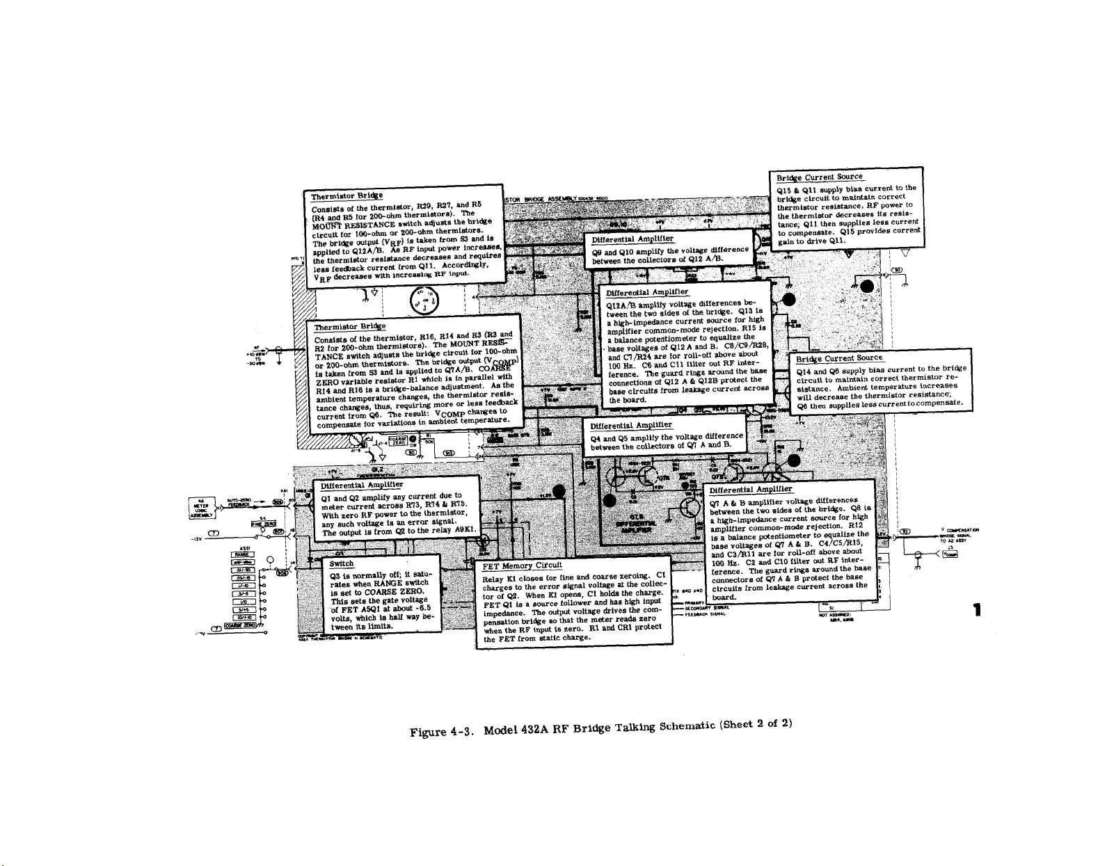
Figure 4-3.
Model 432A
Page 27
Model 432A
4-5
Figure 4-3.
Principles of Operation
Section
IV
Page 28
4-6
Section IV
Principles of Operation
Figure 4-4.
Model 432A
Page 29
Model 432A
4-7
Principles of Operation
Section IV
Figure 4-4.
Page 30

4-8
Section IV
Principles of Operation
Figure 4-5.
Model 432A
Page 31

Model 432A
4-9
Principles of Operation
Section IV
Figure 4-5.
Page 32

Section V
Maintenance
Model 432A
Table 5-1.
5-0
Figure 5-2
Page 33

Model 432A
SECTION V
MAINTENANCE
5-1. INTRODUCTION.
5-2. This section provides information for perfor mance testing, adjusting, troubleshooting and repairing
the 432A Power Meter.
instrument to be checked for conformance to specifications. If performance is not within specifications,
adjust or troubleshoot the instrument.
5-3. CONTENT.
5-4. PERFORMANCE TESTS .
5-5. The procedures test power meter performance
for incoming inspection, periodic evaluation, calibration and troubleshooting, Specifications in Table 1-1
are the performance standards. If the power meter
fails to meet any of the performance test specifications. refer to the troubleshooting diagrams.
Performance tests allow the
Section V
Maintenance
Figure 5-1. Check and Adjustment Test Set -up
5-6. ADJUSTMENTS
5-7. Procedures describe the adjustments necessary
to calibrate the power meter. Adjust the power meter
only when it is determined that the meter is out of
adjustment, and not malfunctioning due to a circuit
failure.
5-8. To avoid errors due to possible ground loop currents, isolate the power meter from ground used for
other auxiliary equipment. A power plug adapter that
removes the ground connection at the line outlet can
be used to isolate the power meter.
5-9. Several circuit components are factory-selected
to meet specific circuit requirements. The factory
selected parts are indicated on the schematic diagrams.
5-10. TEST EQUIPMENT.
5-11. Instruments and accessories required for ad-
justing and testing the power meter are listed and
briefly described in Table 5-1. Instruments used to
maintain the instrument must m e e t or exceed the
specifications given.
5-12. SERVICE INFORMATION.
5-13. Service information in the f o r m of troubleshooting, waveforms, schematics, and component 10cations are given in Section VII. Also, an overall system block diagram is included which contains keyed
numbers corresponding to the test points.
5-14. 432A
PERFORMANCE TESTS
WITH 8477A CALIBRATOR
5-15.
INITIAL SET-UP.
a. Connect the 8477A outputs to the 432A inputs as
shown in Figure 5-1. Use appropriate test equipment
as listed in Table 5-1.
b. If necessary, mechanically zero the meter move-
ment as follows:
(1) With instrument turned off, rotate meter adjust-
ment screw clockwise until pointer approaches
zero mark from the left.
(2) Continue rotating clockwise until pointer coin-
cides with zero mark. If pointer overshoots,
continue rotating adjustment screw clockwise
until pointer once again approaches zero mark
from the left.
(3) Rotate adjustment screw about three degrees
counterclockwise to disengage screw adjustment
from meter suspension.
5-16. METER ACCURACY TEST.
a. Set the 8477A Calibrator controls as follows:
POWER . . . . . . . . . . . . . . . . . . . . . . . . . .. 0.0lmW
FUNCTION . . . . . . . . . . . . . . . . . . . . . . . . . . . . . . . ..
ZERO/TEST . . . . . . . . . . . . . . . . . . . . . . . . . . . . .. ZERO
b. Set the 432A controls as follows:
MOUNT RESISTANCE.. . . . . . . . . . . . . . . . . . .
RANGE . . . . . . . . . . . . . . . . . . . . . . . . . . . . . . . . 0.0lmW
POWER . . . . . . . . . . . . . . . . . . . . . . . . . . . . . . . . . . . .ON
CALIBRATION FACTOR . . . . . . . . . . . . . . . . . . . ...100%
200Ω
..200Ω
5-1
Page 34

Section V
Maintenance
Model 432A
c. Adjust 8477A ZERO knob for 0 volts
cation on the DVM.
d. Set the 8477A controls as follows:
POWER . . . . . . . . . . . . . . . . . . . . . . . .
ZERO/TEST . . . . . . . . . . . . . . . . . . . . . . . . .
e. The digital voltmeter should indicate 1000 ±10
millivolts.
f. The 432A meter should indicate full scale ±1/2
division.
g. Repeat steps d through f for each of the other
ranges. Set the power meter range selector to the
position indicated in Column 1 of Table 5-2, and set
the 8477A meter reading selector to the corresponding
position indicated in Column 2 of Table 5-2. In each
case, the meter indications should correspond to those
shown in Table 5-2, Columns 3 and 4.
Table 5-2. Meter Accuracy Test
±2 mV indi -
.. 0.01mW
TEST
. . . . .
f. Repeat steps d and e for each position of the
CALIBRATION FACTOR selector. In each case, the
digital voltmeter should indicate the voltage shown in
the second column of Table 5-3 for the CALIBRATION
FACTOR shown in the first column.
Table 5-3. Calibration Factor Test
5-17. CALIBRATION FACTOR TEST.
a. Set 432A controls as follows:
RANGE . . . . . . . . . . . . . . . . . . . . . . . . . . . . . . . .
CAL FACTOR . . . . . . . . . . . . . . . . . . . . . . . . . . . . . .
MOUNT RESISTANCE . . . . . . . . . . . . . . . . . . . ...2000
b. Set 8477A controls as follows:
FUNCTION . . . . . . . . . . . . . . . . . . . . . . . . . . . . . . .
ZERO/TEST Switch . . . . . . . . . . . . . . . . . . . . . . . .. TEST
POWER . . . . . . . . . . . . . . . . . . . . . . . . . . . 0.lmW
c. Set 8477A ZERO control sothatthe digital volt-
meter reads 1000 ±2 mV.
d. Set the calibration factor selector to 89%.
e. The digital voltmeter should indicate 989 ±10
millivolts.
0.1 mW
.88%
..200Ω
5-18. METER LINEARITY CHECK.
a. Set the 8477A POWER (MW) selector to 1 mW,
and FUNCTION to
b. Set the 432A RANGE selector to 3 mW, MOUNT
RESISTANCE to
c. The 432A meter should indicate 1 mW ±1/2
division.
d. Set the 8477A POWER (MW) selector to 2 mW.
e. The 432A meter should indicate 2
division.
f. Set the 8477A POWER (MW) selector
g. The 432A m e t e r should indicate 3
division.
5-19. ZERO CARRYOVER TEST.
a. Disconnect the 432A from the 8477A.
b. Turn the 432A power OFF, and connect the ther -
mister mount cable to a thermistor mount.
200Ω, ZERO/TEST switch to TEST.
200Ω.
mW ±1/2
to 3 mW.
mW ±1/2
5-2
Page 35

Model 432A
Figure 5-2. Zero Carryover Test Setup
c.
Set the
432A Power Meter MOUNT RESISTANCE
selector to the resistance shown on the thermistor
mount,
d. Turn ON the 432A power.
e. Connect 141A through ftiltering network to rear
of 432A as shown in Figure 5-2.
Set 141A controls
as follows:
INPUT . . . . . . . . . . . . . . . . . . . . . . . . . . . . . . . . . . . . .DC
Sensitivity . . . . . . . . . . . . . . . . . . . . . . . . . .
SWEEPT ICE . . . . . . . . . . . . . . . . . . . . . . . . . .
TRIGGER LEVEL . . . . . . . .
max clockwise (free run)
1 mV/cm
2 see/cm
f. Zero the 432A as follows:
1) Set the RANGE selector maximum cw to
COARSE ZERO.
2) Set the COARSE ZERO screwdriver adjust so
that the meter indicates zero.
3) Set 432 ARANGE switch to .01 mW. Depress
the FINE ZERO switch. The meter indication
should to to zero without overshoot.
g. Rotate the RANGE switch clockwise, one step at
a time, while the oscilloscope is sweeping. On each
432 A range, the scope trace should be within .0lmW
divisions (±5 mV) from where it was on the .01 mWrange,
5-20. FINE ZERO RANGE CHECK.
a. Set the 432A RANGE selector to 0.3 mW. Leave
the thermistor mount connected to the cable, and the
MOUNT RESISTANCE selector set to correspond to
the resistance of the mount used.
b. Depress the FINE ZERO switch.
c. Slowly turn the COARSE ZERO screwdriver adjustment counterclockwise until the meter will no
longer zero. The FINE zero circuit is at one end of
its range.
d. Release FINE ZERO.
e. Set the COARSE ZERO screwdriver adjustment
so that the meter indicates full scale on the 0-3 scale
(0.3 ‘mW range).
Section V
Maintenance
f. Depress FINE ZERO switch (the fine zero circuit
is at the other end of its range). Meter should indicate
below 2 on the 0-3 scale. Record the indication.
g. Release FINE ZERO.
h. Rotate RANGE switch to COARSE ZERO position.
The fine zero circuit is now in the center of its range.
The meter reading should be (1.5 + reading of +1/2 of
reading in step f, ±0.1 on the 0-3 scale.
5-21. 432A CALIBRATION WITHOUT 8477A
CALIBRATOR
5-22. The 432A Power Meter can be calibrated without an 8477A Calibrator using a method similar to the
precision power method outlined in Paragraph 3-27.
5-23. A major difference between the two measurements is that external power need not be applied when
calibrating the instrument. Normally, in a stable environment, the V
output voltage remains con-
COMP
stant, not being affected by external RF power; only
the V
RF output varies during power measurement.
Since the power that the meter indicates is proportional to V
to indicate a power also by holding V
varying V
COMP and VRF, we can cause the meter
RF constant and
COMP. This is easily done on the 432A by
turning the COARSE ZERO control. Two calibration
procedures are given below.
5-24. CALIBRATION PROCEDURE 1.
a. Connect thermistor mount to power meter; let
instrument warm up for at least 10 minutes.
b. Select range which instrument is to be calibrated
on. Note: ranges below 0.3 mW require a precise
differential voltmeter capable of resolving 1 µV. The
HP 740B DC Standard/A Voltmeter, which has an accuracy of ±(0.005% of reading ±0.0004%ofrange ±1µV)
is recommended. A digital voltmeter is adequate for
the 1.0 mW and higher ranges.
c. Connect Differential Voltmeter (or DVM differentially) between the V
on the rear panel. See Figure 3-3 for location of V
and VCOMP outputs.
d. While pressing the FINE ZERO switch, measure
and record V
0. (V. is the difference of the bridge
voltages with no power applied. )
e. Turn COARSE ZERO control (on front panel)
clockwise to a convenient power, e.g., 9 on the zero to
10 scale or 2 on the 0 to 3 scale.
f. Differentially measure and record V
difference voltage between V
power applied.
g. Measure and record V
V
COMP jack is isolated from chassis ground; measure
from the center conductor of the BNC to the outer
conductor.
COMP and VRF output jacks
1. V1 is the
COMP and VRF with
COMP. Note that the
5-3
R
F
Page 36

Page 37

Model 432A
Section V
Maintenance
INSTRUMENT SERIAL NO.
DATE
TABLE 5-4. PERFORMANCE TEST CARD
Data in this test card corresponds to Performance Tests in
Paragraphs 5-16 through 5-20.
5-5
Page 38

Section V
Maintenance
Model 432A
TABLE 5-4. PERFORMANCE TEST CARD
Para. Measurement
Ref. Test
5-16
e
f
METER ACCURACY
0.01 mW applied; measure RECORDER OUT voltage
Meter indicates full-scale (0-1 scale)
Unit
mVdc
divisions
Repeat on remaining 432A power ranges:
e
f
e
f
e
f
e
f
e
f
Power applied: 0.03 mW
Meter indication (0-3 scale)
Power applied: 0.1 mW
Meter indication (0-1 scale)
Power applied: 0. 3 mW mVdc 938.8 958.8
Meter indication (0-3 scale)
Power applied: 1 mW
Meter indication (0-1 scale)
Power applied: 3 mW
Meter indication (0-3 scale)
mVdc
divisions -1/2
m.Vdc 990 1010
divisions -1/2
divisions -1/2
mVdc
divisions -1/2
mVdc
divisions
Min.
990
-1/2
Actual Max.
1010
+ 1,/2
938.8 958.8
+ 1,/2
+1/2
+1/2
990
1010
+ 1/2
938.8 958.8
-1/2
+1/2
e
f
5-17
i
Power applied: 10 mW
Meter indication (0-1 scale)
CALIBRATION FACTOR
Calibration Factor (%)
88
89
90
91 967
92 957
93
94
95
96
97
98
99
100
DVM Reading (mVdc )
1000
989
9’78
946
935
926
916
907
897
889
880
mVdc
divisions
mVdc
mVdc
mVdc
mVdc
mVdc
mVdc
mVdc
mVdc
mVdc
mVdc
mVdc
mVdc
mVdc
990
-1/2
990
1010
+ 1,/2
1010
979 999
968
957
947
936
925
916
906
988
977
967
956
945
936
926
897 917
887
879
907
899
870 890
5-6
Page 39

Model 432A
Section V
Maintenance
TABLE 5-4. PERFORMANCE TEST CARD
Para.
Ref.
5-18
c
e
g
5-19
d
Test
Unit
METER LINEARITY
1 mW applied, 3 mW scale: meter indicates 1 mW divisions
2 mW applied, 3 mW scale: meter indicates 2 mW divisions
3 mW applied, 3 mW scale: meter indicates 3 mW divisions
ZERO CARRY-OVER
Zero carry-over:
Measurement
Range (mW)
.01
.03 0 ±5 mVdc
.1
.3
1
3
10
Scope Indication
0 ±5 mVdc
0 ±5 mVdc
0 ±5 mVdc
0 ±5 mVdc
0 ±5 mVdc
0 ±5 mVdc mVdc
mVdc
mVdc -5
mVdc -5
mVdc -5
mVdc -5
mVdc
Min.
-1/2
-1/2
-1/2
-5
-5
-5
Actual Max.
+1/2
+1/2
+1/2
+5
+5
+5
+5
+5
+5
+5
5-20
f
g
FINE ZERO RANGE
Meter indication on 1-3 scale:
Meter indication on 1-3 scale: 1.5+ 1/2 reading
of step f.
divisions
divisions
1.75
2.0
1.5
5-7
Page 40

Model 432A
h. Calculate the power using the following formula?
where R is the resistance of the thermistor mount and
should be identical to the setting of the MOUNT RESISTANCE switch.
i. If calculated power is different from the value
that was set with the COARSE ZERO control, adjust
A2R6 so that the meter reads calculated power. If the
range of A2R6 is insufficient to set new power, it will
be necessary to change the value of A2R70.
j. Set COARSE ZERO so that meter reads one on
the 0 to 1’scale. Set A2R72 for 1.000 V±10 mV at the
RECORDER output jack on the rear panel.
5-25. There is a simpler form of the equation that
was used to calculate power in step h above. This
form ignores V
tween the two bridges with no power applied. How-
, the small voltage difference be-
o
ever, V. becomes negligible on the higher ranges,
that is, 1 mV and above, and can be ignored with little
decrease in accuracy. I’he simpler form is as follows:
5-26. CALIBRATION PROCEDURE 2.
a. Connect thermistor mount to power meter; let
instrument warm up for at least 10 minutes.
b. Select 1, 3, or 10 mW range.
c. Turn the COARSE ZERO control clockwise to
indicate some convenient on- scale reading.
d. Measure V
COMP and record. Note that VCOMP
jack is isolated from chassis ground; measure from
the center conductor of the BNC to the outer conductor.
e. Measure V
RF and record. Follow measurement
procedure in step d.
f. Measure and record V
COMP - VRF. This term
must be measured differentially, that is, one side of
the DVM connected to V
nected to V
RF. In this way the full resolution of the
COMP and the other side con-
DVM can be used.
g. Substituting the measured values into the above
formula, calculate the power,
h. If calculated power is different from the power
set with the COARSE ZERO control, adjust A2R6 so
that meter indicates that power. If the range of A2R6
is not great enough to set new power level, the value
of A2R70 will have to be changed.
i. Adjust COARSE ZERO so that meter reads 1 on
the O to 1 scale. Set A2R72 for 1.000 V ±10 mV at the
RECORDER output jack on the rear panel.
*This formula is accurate for on- scale readings; how-
ever, with no power applied (i. e., V
solveto P = O because of a deleted term + V
1 = V0) it does not
0. This
term can be neglected for any on-scale reading.
5-8
Section V
Maintenance
COVER REMOVAL AND
5-27.
REPLACEMENT.
The side covers can be removed and replaced
5-28.
independently of the top and bottom covers. Each side
cover is held in place by four screws retained by nuts
which are fastened to the side frames.
5-29. TOP COVER REMOVAL.
a. At the rear of the instrument, remove the screw
that retains the cover.
b. Grasp the cover from the rear, and slide it back
1/2 inch. Then tilt forward edge of the cover upward
and lift the cover from the instrument.
5-30. TOP COVER REPLACEMENT.
a. Rest the cover flat on the cast guides projecting
inward near the top of each side frame.
b. Slide t h e cover forward, allowing its forward
edge to enter the groove in the front panel.
c. Replace the cover retaining screw.
5-31. BOTTOM COVER REMOVAL.
a. Remove the retaining screw at the rear of the
cover.
b. Swing the tilt stand out to free the cover
c. Slide the cover rearward far enough to free the
forward edge.
d. Tilt the forward edge of the cover upward and
lift the cover from the instrument.
5-32. BOTTOM COVER REPLACEMENT.
a. Set the tilt stand out of the way of the cover
b. Rest the bottom cover flat on the cast guides
projecting inward near the bottom of each side frame.
c. Slide the cover forward on the guides so that the
formed portion at the rear of the cover slides over the
two short projections at the rear corner of each side
frame.
d. Replace the retaining screw.
5-33. ADJUSTMENT PROCEDURES.
5-34. INITIAL SETUP.
a. Remove the power meter side panels.
b. Connect the equipment as shown in Figure 5-1.
Refer to Table 5-1 for equipment specifications.
5-35. MECHANICAL METER ADJUSTMENT.
a. Whenthe meter is properly zero-set, the pointer
rests over the zero mark on the meter scale when the
instrument is:
(1) at normal operating temperature
(2) in its normal operating position
(3) turned off
Page 41

Section V
Maintenance
Model 432A
b. Set the pointer as follows to obtain best accuracy
and mechanical stability:
(1) Turn instrument off.
(2) Rotate the meter mechanical adjustment screw
clockwise until the meter pointer is to the left
of zero and moving up the scale toward zero.
Stop when the pointer is exactly over the zero
mark. If the pointer overshoots, repeat step 2.
(3) When the pointer is exactly on zero, rotate the
adjustment screw approximately 3 d e g r e es
counterclockwise. This frees the adjustment
screw from the meter suspension. If the pointer
moves during this step, repeat steps 2 and 3.
5-36. BRIDGE AMPLIFIER TESTS
a. Connect equipment as shown in Figure 5-3.
b. Compensation Bridge.
1. Connect 3440A/3443A between A1TP5 and
A1TP6 (using 10K isolation resistors).
2. Make the following settings:
RANGE . . . . . . . . . . . . . . . . . . . . . . . . . . . .l0mW
MOUNT RESISTANCE . . . . . . . . . . . . . .
FUNCTION . . . . . . . . . . . . . . . . . . . . . . . . .. SET
3. Adjust A1R12 (OFFSET ADJUST) for 0.0 ±0.1
mV dc reading on the digital voltmeter.
4. Change 8477A FUNCTION to CHECK. The
digital VM reading should not exceed ±0.4
mVdc.
c . RF BRIDGE
1. Connect DVM between A1TP3 and AlTP4
using 10
the leads.
3. Set 8477A FUNCTION to SET. Adjust A1R15
(OFFSET ADJUST) for DVM reading of 0.0
± 0.1 mVdc.
432A
..200Ω
8477A
κΩ isolation resistors in series with
4. Change 8477A FUNCTION to CHECK. The
reading should not exceed ±0.4 mVdc.
Note: Failure of the instrument to meet the specification of steps (4) of b and c above indicates insufficient
bridge gain. Refer to Table 7-3 or 7-4 in the trouble-
shooting section.
5-37. METER AND RECORDER OUTPUT
CALIBRATION
a. Connect the DVM to the 432A RECORDER output.
b. Set 8477A controls as follows:
FUNCTION . . . . . . . . . . . . . . . . . . . .
ZERO/TEST . . . . . . . . . . . . . . . . .. ZERO
POWER . . . . . . . . . . . . . . . . . . . . . . . 1mw
c. Set 432A controls as follows:
MOUNT RES . . . . . . . . . . . . . . . . . . .
RANGE . . . . . . . . . . . . . . . . . . . . . . . . . lmW
CAL FACTOR . . . . . . . . . . . . . . . . . . .
d. Adjust ZERO control on 8477A for DVM indica-
tion of 0.000 ±.00IV.
e. ZERO/TEST on 8477A to TEST
f. Adjust A2R6 in 432A for 432A meter reading of
1.0 mW ±.01 mW.
g. Adjust A2R74 in 432A for DVM reading of 1.0V
±.001V
h.
Change the following settings:
432A RANGE to 10 mW
8477A POWER (mW) to 10 mW and ZERO/
TEST to ZERO.
Note: When switching 432A to 10 mW or switching from 10 mW to any other range, the meter
will react slowly for a short period. This is due
to time constants in the instrument and is normal.
i.
Zero instrument as in step d and c.
200Ω
.200Ω
100%
Figure 5-3. Bridge Amplifier Test
Adjust A2R86 for DVM reading of 1.00 ±.00 IV.
j.
Return 432A RANGE and 8477A POWER switches
k.
to 1 mW and zero as before.
1. Adjust A2R6 for DVM reading of 1.000 ±.00 1V.
m. Perform the adjustments of steps h through 1
again until 432A reads 1 ±.010V (at recorder output)
on both 1 mW and 10 mW ranges.
n. Turn to the beginning of this section; verify that
the instrument meets its specifications by completing
the PERFORMANCE TESTS.
5-38. BATTERY CHARGER ADJUSTMENT
(OPTION 01 ONLY)
a.b.Remove the power meter top panel.
Connect 432A to ac line power and turn ON.
5-9
Page 42

Model 432A
c. Set A7R8 fully clockwise for maximum battery
charge rate.
d. With the digital voltmeter, measure the voltage
between A7TP1 and A7TP2.
e. Adjust A7R8 for digital voltmeter reading of 0.2
to 0.4 volts (20 to 40 mA through R3).
Section V
Maintenance
5-43. To check a transistor, first see if the emitterbase diode is forward-biased by measuring the voltage
difference between emitter and base. When using an
electronic voltmeter, do not measure directly between
emitter and base; there may be sufficient loop current
between the voltmeter lead to damage the transistor.
Instead, measure each voltage separately with respect
to a voltage common point (e.g. , chassis).
f. Disconnect the test equipment and power and re-
place the power meter top and side panels.
5-39. BATTERY REMOVAL
a. Remove the top cover.
b. Remove the two Phillips screws on the top rear
of the battery cover.
c. Lift off the battery cover.
d. Loosen the nuts on the battery binding posts.
e. Lift out the battery.
5-40.
ISOLATING TROUBLE IN TRANSISTOR
CIRCUITS.
5-41. General. The following information should help
determine if a transistor works. There are tests for
both in-circuit and out -of -circuit transistors, which
help to determine if a particular trouble is due to a
faulty transistor or some other component. See Figure 5-2.
5-42. hi-circuit Testing. Intransistor Circuit testing
the most important consideration is the transistor
base-emitter junction. Like the control g r id of a
vacuum tube, this is the control point in the transistor.
5-44. If the transistor base-emitter junction is
forward-biased, the transistor conducts. If the diode
is heavily forward-biased, the transistor saturates.
However, if the base -emitter diode is reverse-biased,
the transistor is cut off (open). The voltage drop across
a forward-biased emitter-base junction varies with
transistor collector current. A germanium transistor
has a typical base -emitter voltage of 0.2-0.3 volt with
1-10 mA collector current, and 0.4-0.5 volt with 10100 mA collector current. In contrast, base-emitter
voltage for silicon transistors is about twice that for
germanium types; about 0.5-0.6 volt for low collector
current, and about 0.8-0.9 for high collector current.
5-45. If the emitter base-junction is forward-biased,
check for amplifier action by short-circuiting base to
emitter while observing collector voltage. The transistor should stop conduction (cut off), which should
shift the collector voltage close to the supply voltage.
Any difference is due to current leadage through the
transistor.
In general, the smaller the current, the
better the transistor. If collector voltage does not
change, the transistor has either an emitter-collector
short circuit or emitter-base open circuit.
5-46. OUT-OF-CIRCUIT TESTING,
5-47. The two common causes of transistor failure
are internal short - and open-circuits. Remove the
transistor from the circuit and use an ohmmeter to
measure internal resistance. See Table 5-5 for meas-
urement data.
Table 5-5. Out-of-Circuit Transistor Resistance Measurements
Transistor Type
Positive Lead to
I I
Small Signal
emitter
emitter
PNP Germanium
Power
emitter base*
emitter
Small Signal
base
collector
NPN Silicon
Power
base
collector emitter
To test for transistor action, add collector -base short.
5-10
Connect Ohmmeter
Negative Lead to Measure Resistance (ohms)
base *
collector
collector several hundred
emitter
emitter very high (might read open)
emitter
Measured resistance should decrease.
I
200-500
10K - l00K
30-50
lK - 3K
200 -1000
high, often greater than lM
Page 43

Section V
Maintenance
Model 432A
Figure 5-4. Transistor Biasing and Operating Characteristics
5-11
Page 44

Model 432A
Section V
Maintenance
Table 5-6. Etched Circuit Soldering Equipment
Table 5-7
5-12
Page 45

Section V
Maintenance
Model 432A
5-48. COMPONENT REPLACEMENT IN
ETCHED CIRCUITS.
5-49. General. Etched circuit boards are sensitive
to heat and to scratches with sharp objects. This is
because the conductors are plated o n t o the circuit
boards and the plating extends through the component
mounting holes. Whenever possible, avoid unnecessary component substitution; it can damage the circuit
board and adjacent components. See Table 5-6 for
recommended tools and materials.
5-50. AXIAL-LEAD COMPONENTS .
5-51. Resistors, tubular capacitors and other axial-
lead components can be replaced without unsoldering,
Cut the component leads near the body of the defective
component, remove the component and straighten the
leads left in the board. Wrap leads of the replacement
component one turn around the original leads, solder
the connection, and clip off the excess lead.
5-52. OTHER COMPONENTS.
5-53. Replace other components as follows:
a. Remove defective component from circuit board.
Use a low-power soldering iron because excessive
heat may lift a conductor or damage the board.
b. Remove solder from mounting holes with a suc-
tion device or a wooden toothpick. DO NOT USE A
SHARP METAL OBJECT SUCH AS AN AWL OR TWIST
DRILL. SHARP OBJECTS MAY DAMAGE THE
PLATED-THROUGH CONDUCTOR.
c. Shape the leads of the replacement component to
mat ch the mounting-hole spacing.
d. Insert the component leads in the mounting holes
and position it as the original was. DO NOT FORCE
LEADS OF REPLACEMENT COMPONENT INTO
MOUNTING HOLES. A sharp edge on the lead may
damage the plated -through conductor.
e. Solder the component in place and remove excess
flux from the soldered a r e as. Apply a protective
coating to prevent contamination and corrosion. See
Table 5-6 for recommendations.
CAUTION
Most ohmmeters can supply enough current
or voltage to damage a transistor. Before
using an ohmmeter to measure transistor
forward or reverse resistance, c h e c k its
open -circuit voltage and short -circuit cur -
rent output ON THE RANGE TO BE USED.
Open-circuit voltage must not exceed 1.5volts
and short-circuit current must be less than
3 mA.
5-13
Page 46

Page 47

SECTION VI
REPLACEABLE PARTS
6-1. INTRODUCTION.
6-2. This section contains information for ordering
replacement parts. Table 6-1 lists parts in alpha-
numerical order of their reference designators and
indicates the description and HP stock number of each
part, together with any applicable notes. Miscellaneous parts are listed at the end of Table 6-1, Table
6-2 lists parts in alpha-numerical order of their HP
stock number and provides the following information
on each part:
a. Description.
b. Manufacturer of the part in a five-digit code;
see list of manufacturers in Table 6-3.
c. Manufacturer’s part number.
d. Total quantity used (TQ column).
REFERSNCE DESIGNATORS
A=
B=
BT
=
c=
CP
CR :
DL
=
DS
=
E=
.4=
AFC =
AMPL
=
BFO
=
BE W
BH
=
BP
=
BRS
=
BWO
=
Ccw
=
CER
=
CMO
=
COEF
=
COM
=
cCmfP
=
COMPL
CONN
=
CP
=
CRT
=
Cw
=
DEPC
=
DR
=
ELEcT
EN CAP
EXT
=
F
FH =
FIL H
m=
G=
01194-13
assembly
motor
battery
capacitor
coupler
diode
delay line
dmrice sisnaling (lamp)
mist electronic part
amperes
automatic frequency cent rol
amplifier
beat frequency oscillator
berylltum copper
=
btnder head
bamfpaBs
brass
backward wave oscillator
counter-clockwise
Ceratic
cabinet mount 0.19
coefficient
common
compaeition
complete
=
connector
cadmium plate
cathode -ray tube
c10ckwi6e
deposit ed cartwn
drive
electrolytic
=
encapsulated
=
external
farads
flat head
fintst er head
=
ftxed
gisa (109)
r e rmanium
ikss
gronndf ed)
F
FL
Ic
J
K
L
Ls
M
fdK
H
HDw
HEX
HG
HR
Hz
IF
IMPG
fNCD
lNC L
ms
INT
K
Lff
LIN
LK WASH
LOG
LPF
M
MEG
MET FLM
MET OX
MFR
MHZ
fdfNAT
MOM
MTG
hfY
N
N/C
NE
Nf PL
fuse
.
filter
integrated ckrcult
jack
relay RT
inductor
loud spe&ker
meter TB
.
microphone
ABBRZVL4TIONS
henries
hardware
hexagonaf
mercury
hour(s)
hertz
intermediate freq
Wnpregmated
.
tncandeecent
include(s)
insulation
fnternal
kno
=
1000
left hand
linear taper
lock washer
logarithmic taper
low pass filter
miUi
=
10-3
meg
= 106
metal film
metallic oxide
manufacturer
mega hertz
.
mintature
momentazy
mounting
,.my~r. t
nano (10-9)
normally closed
neon
nickel plate
6-3.
6-4.
Appendix D
table D-1
To obtain apart that is not listed, include:
6-5.
Instrument model number.
a
+
Instrument serial number.
b.
Description of the part.
c.
Function and location of the part.
d.
MP
:
R
s
T
TP
N/O
Nm
NPN
NRFR
NSR
OBD
on
ox
P
Pc
PF
PH BRZ
PHL
PIV
PNP
P/o
mLY
mRc
ms
mT
PP
PT
Pwv
RECT
RF
m
mechanical part
plug
transistor
.
resistor
thermistor
switch
transfmmer
terminal board
test point
normafly open
negative positive zero
(zero temperature
coefficient)
negative -PO sitive negative
.
not recommended for
field replacement
not separately
replaceable
order by description
oval bead
oxide
peak
f~f::a:~=”;ofarade
phosphor bronze
Phillips
peak inverse voltage
positive-negative positive
part of
polystyrene
prcelain
position(s)
potentiometer
peak-to-peak
point
peak working voltage
rectifier
radio frequency
round head or
right hand
v
VR
=
w
x
Y
z
RMO
Riws
RWV
S-B
SCR
SE
SECT
SEMICON
Sf=
SfL
SL
SPG
SPL
SST
SR
sTL
12
TA
TD
TGL
THD
TI
TOL
TRfM
TWT
u
VAR
VDCW
WI
w
Wfv
w
w/o
.
vacuum, tube, neon
bulb, photocell, etc.
voltage regulator
cable
socket
Crystal
tuned cavity,
net work
rack mount only
root- mean square
reverse working
voltage
slow-blow
screw
selenium
aection(
semicontictor
=
silicon
silver
.
slide
spring
special
.
stainless steel
split ring
steel
tantalum
time delay
toggle
thread
titanium
tolerance
trimmer
traveling wave tube
micro
variable
dc working volts
with
watta
working inverse
voltage
wirewmmd
without
.9)
=
IO-6
6-1
Page 48

Section VI
Parts
Reference
Designation
@ Part
Table 6-1. Reference Designation Index
No.
Description
Model 432A
#
Note
Al
AIC1
A1C2
A1C3
A1C4
ALC5
A1C6
AIC7
A1C8
A1C9
A1C1O
AIC1l
A1C12
A1C13
A1C14
ALCR1
A1CR2
AIQ1
A1Q2
A1Q3
AlQ4
A1Q5
AlQ6
klQ7
A1Q8
A1Q9
A1Q1O
AIQ1l
A1Q12
A1Q13
A1Q14
hlQ15
tilRl
hlR2
A1R3
41R4
?41R5
klR6
00432-6001
00432–2001
0180-0374
0160-2930
0160–2930
0160-0380
0160-2930
0160-2930
0160–2930
0160–0380
0160-2930
0160-2930
0160–29>0
0180-0374
0160-2264
0160–2264
1901–0040
1901-0040
1S53-0020
1853–0020
1853–0020
1854–0071
1854-0071
1853-0001
1854-0221
1854-0071
1854-0071
1854-0071
1853-0001
1854-0221
1854-0071
1853-0020
1853-OOZLI
0698-3260
0686–1055
0698–3160
0698-3160
0698-31b0
13LIAR0
AS
SY:BRIOGE
tMJARO: BLANK
C:FXD ELECT
C:FXO
CER
C:FXD
CER
C:FXO MY 0.22
C:FXO
CER
C:FXO
CER
(,:FXD
CER
C:FXO MY 0.22
C:FXO
CER
(,:FXD
CER
C,:FXD
CER
C:FXD ELECT 10
C:FXD
CER 20 PF 5% 500VOCW
L:FXO
CER 20 PF 5%
DIDDE:SILICON
I)1OOE:SILICON
TRANSISTOR:SILICON
TRANSISTOR: SILICON
TRANSISTOR:SILICON
TRANSISTOR:SILICON
TRANSISTOR:SILICON
TRANSISTOR:PNP
TRANSISTOR OUAL:SILICON
FAcToRY SELECTED
TRANSISTOR: SILICON
TRANSISTOR:SILICON
TRANSISTOR:SILICON
TRANSISTOR:PNP SILICON 30V 900MW
TRANSISTOR OUAL:SILICON
FACTORY
TKANSISTOR:SILICON
TRANSISTOR: SILICON
TRANSISTOR:SILICON
R:FXO
MET FLM
R:FXO
COMP 1 MEGOHM 5%
R:FXD
MET FLM
NOT
ASSIGNEO
R:FXO
MET FLM
R:FXO
MET FLM
PC
10 UF
0.01
0.01
0.01
0.01
0.01 UF +S0–20% 100VDCW
0.01
0.01
0.01
SELECTEO
10%, 20VOCH
UF
+80-20% loovoGH
UF
+80-20% 100VDCH
UF 10%
UF
UF
UF 10%
UF
UF
UF
UF 10% 20VOCW
30MA 30WV
30MA
464K
3L.6K
31.6K
31.6K
200VDCW
+80-20% loovDcH
+80-20% 100VOCW
200VDCW
+80-20% 100VOCW
+80-20% 100VOCW
+80–20% 100VOCW
500VOCW
30WV
PNP
PNP
PNP
NPN
NPN
SILICON 30V 900MW
PART
PART
NPN
NPN
NPN
NPN
NPN
NPN
PNP
PNP
OHM 1%
l/2W
OHM 1%
OHM 1%
OHM 1%
l/8W
l/8W
l/8W
l/8W
6-2
# See introduction to this section for ordering information
Page 49

Model 432A
Reference
13ximmtinn
--- .---.-.-
A1R7
itlRO
A1R9
AIRIO
AIR1l
A1R12
A1R13
A1R14
AIR15
A1R16
A1R17
A1R18
A1R19
A1R20
A1R21
&lR22
&LR23
blR24
hAR25
klR26
&lRZ7
tIlR213
klR29
A1R30
A1R31
&lR32
kLR33
iilR34
fIlR35
filR36
klR37
klR38
4LR39
41R40
klR41
klR42
klR43
41
illAl
@ Part
0698-3156
0757-0465
0698-3136
0698-3441
0757-0416
2100-1770
0757-046L
0811-2284
2100-1770
0811–2284
0757–0199
0698-3441
0698-3160
0698-3160
0698–3156
0757–0465
0757-0416
0757-0461
0811-2284
0757-C199
0811-2284
0757-0199
0698-3260
0757-0465
0757–0465
0757-0442
0757-0279
0757-0279
0757-0279
0757-0279
0698-3160
0698-3160
0757-0442
0360-0124
00432-6011
Table 6-1. Reference Designation Index (Cont‘d)
No.
I
R:FXD
MET FLM 14.7K OHM 1% l/8W
R:FXO
MET FLM
R:FXO
MET FLM 17.8K OHM 1X l/8W
R:FXO
MET FLM 215 OHM
R:FXO
MET FLM
R:VAR WW 100
R:FXO
MET FLM 68.lK OHM
R:FXD WW lK
R:VAR WW
R:FXD WH lK
R:FXO
MET FLM 21.5K OHM 1% l/8W
NOT
ASSIGNEO
R:FXO
MET FLM 215 OHM 1% l/8W
R:FXO
MET FLM 31.6K OHM 1% l/8W
R:FXD
MET FLM 31.6K OHM 1X l/8M
R:FXD
MET FLM 14.7K OHM 1% l/8W
R:FXD
MET FLM LOOK OHM 1% l/8W
K:FXO
MET FLM
NOT
ASSIGNED
R:FXD
MET FLM 68.IK OHM 1% l/81i
R:FXO WW lK
K:FXO
MET FLM 21.5K OHM 1% l/8W
R:FXD WW lK
R:FXD
MET FLM 21.5K OHM 1% l/8W
R:FXO
MET FLM
NOT
ASSIGNEO
R:FXD
MET FLM
R:FXD
MET FLM
R:FXO
MET FLM 10.OK OHM 1% l/8H
R:FXO
MET
R:FXO
MET FLM 3.16K OHM 1% l/8kJ
k:FXD MET FLM 3.16K OHM 1% l/8H
R:FXO
MET FLM 3.16K OHM 1% l/8W
R:FXO
MET
R:FXO
MET FLPl 31.6K OHM 1X l/8W
N(IT ASSIGNED
R:FXO
MET FLM
TERMINAL:SOLDER
ASSY:AUTO
100K
511
OHM 10% LIN l/2W
OHM 0.1% l/40W
100 OHM 10% LIN l/2kl
OHM 0.1% l/40W
511
OHM 0.1% l/40W
OHM 0.1% l/40W
464K
100K
100K
FLil
FLfl
LO.DK
ZERO
Description
OHM 1X l/SH
1X
OHM 1% l/8W
OHM
3.16K OHM 1% l/8W
3L.6K OHM 1% l/SW
LUG
l/8W
1X
1X
l/8W
OHM
1X
l/8W
OHM 1% l/8W
OHM 1% l/8H
OHM 1% l/8W
l/8H
Section VI
Parts
#
Note
I
# See introduction to this section for ordering information
6-3
Page 50

Section VI
Parts
Reference
Designation
@ Part No.
Table 6-1. Reference Designation Index (Cont’d)
Description #
Model 432A
Note
/42
A2C1
A2C2
A2C3
A2C4
A2C5
A2C6A2C20
A2C21
A2C22
A2C23
A2C24
A2C25
A2C26
A2C
A2C28
A2C29
A2C3C
A2C3 1
A2C32
A2C33
A2C34
A2C35
A2C36
A2C37
A2C38
A2C39
A2C40
A2C41
A2C42
A2C43
A2C44
A2C45
A2C46
A2C47
A2C48
A2C49
A2C50
A2CR 1
A2CR2
A2CR 3
A2CR4
A2CR5
00432–6015
00432 -2u15
01 S0-1819
0180-0229
0160-2917
0160–2917
0140–0234
0140–0234
0180-1746
0160–0978
27
0160-2930
0180–2178
0160-2930
01s0-1940
0180-0197
0160–2672
0180-0197
0160-2917
0160-2917
0160-2150
0180-0229
0160-2917
0180–0106
01s0-0197
0180-0291
0180-0106
0150-0059
0160-2930
0140–0192
0180–0229
0160-2917
1901-0026
1901-0026
1901–0026
1901–0026
BOARO AS
BOAR D:
L:FXD ELECT 100
C:FXD ELECT 33
C:FXD
NUT
C:FXD CER. 0.05
NOT
NOT
L:FXO MICA 500
C:FXD MICA 500
L:FXO ELECT 15
NiJT ASSIGNED
(,:FXD MICA 150J
C:FXD
NOT
l\OT ASSIGNEO
C:FXO ELECT 220
L:FXD
L:FXD ELECT 33
NOT
(,:FXO ELECT 2.2
L:FXO MY 0.047
C:FXO ELECT 2.2
C:FXD
NUT
C:FXD
L.:FXO MICA 33
C:FXD ELECT 33
C:FXD
C:FXD ELECT 60
C:FXD ELECT 2.2
C:FXD ELECT 1.0 UF 10% 35VDCW
C:FXD ELECT 60
C.:FXD
C:FXD
C:FXD MICA 68
L:FXD ELECT 33
C:FXD
LIIOOE:SILICON
D1ODE:S1LICON
DIDDE:SILICON
OIOOE:SILICON
NOT ASSIGNED
SY: LOGIC
BLANK
PC
UF
CER
ASSIGNEO
ASSIGNED
ASSIGNEO
CER
ASSIGNED
CER
ASSIGNED
CER
ASSIGNED
CER
CER
CER
CER
CER
UF 10% 10VDCW
0.05
UF
+80-20% 100VDCW
UF
+80-20% 100VDCW
PF 1%
PF
1%
UF 10%
PF 1%
0.01
UF
+80-20% 100VDCW
UF
0.01
UF
+80-20% 100VDCW
UF 10% 15VOCW
UF 10%
UF
5.%’ 80VOCH
UF 10% 20VDCW
0.05 UF +80–20% 100VDCW
0.05
UF
+80-20% 100VDCW
PF 5%
UF
10Z
0.05
UF
+80-20% 100VOCW
UF
20%
UF 10% 20VOCW
UF
20%
3.3-0.25
0.01
0.05
PF
UF
+80-20% 100VDCW
PF 5%
UF 10% 10VDCW
UF
+80-20% 100VDCW
0.75A 200 PIV
0.75A 200 PIV
0.75A 200 PIV
0.75A 200 PIV
+75-10%
20VDCW
500VDCW
20%
8VOCW
10VDCW
6VDCW
6VDCW
500VDCW
50VOCW
20VDCW
6-4
# See introduction to this section for ordering information
Page 51

Model 432A
Reference
Designation
@ Part No.
Table 6-1. Reference Designation Index (Cont’d)
Description #
Section VI
Parts
Note
A2CR6
A2CR7
A2CRI?
A2CR9
A2LR1O
A2CUll
A2c R12
A2CR13
A2CR14
A2cR15
A2C.
R16
A2CR17
A2CR18
A2CR19
A2CR 20
A2CR21
A2CR22
A2CR23
A2Q1
A2Q2
A2Q
3
A2 C14
AZQ5
A2Q6
A2Q7
A2Q8
A2Q9
A2Q1O
A2C?11
A2Q12AZ f.i19
A2Q2C
A2Q2 1
A2Q22
A2Q22
A2Q24
A2Q25
A2Q26
A2Q27
A2Q28
A2Q29
A2Q3 O
A2Q31
F12Q32
AZQ33
!%2Q34
h2C35
&2Q36
1902-0033
1901–004U
1901–0026
1901–0040
1901-0040
1901-0040
190 I–004L)
1901-0040
1901–0040
1901–0040
L901–004U
1901-0040
1901-0040
1901-0040
1901–0040
1901-0040
lS54–007i
1854–0062
1854-0071
1853-0012
1853–OOfO
1S53–0020
1853–0020
1854-0071
1854–0003
1853-0001
1854-0071
1853-0020
1854-0005
1854–0071
1854-0071
1854-0005
1854–007A
1854–0071
1854-CD09
1854–0009
1855-0062
1S55-0062
1854–0071
1854-0071
1853-0015
DIODE SREAKDOWN:6.2V
tiIcIi7E:sILxc0N
DIOOE:SILICON
NOT
ASSIGNED
NGT
ASSIGNEO
DXODE:SILICON
OIGDE:SILICON
L)IOOE:SILICON
DIODE:SILICON
DIODE:SILICON
I)1OOE:SILICON
OIODE:SILICON
DIODE:SILICON
i2100E:SILICON
DIODE:SILICON
D1ODE:SILICDN
DIOOE:SILICON
OIOOE:SILICON
TRANSISTOR: SILICON
TRANSISTOR:SILICON
TKANSISTOR:SILICON
TRANSISTOR:PNP
TRANS1ST13R: S1LICON
TRANSISTOR:SILICON
TRANSISTOR: SI’LICON
TRANSISTOR: SILICON
TKANSISTOR:NPN
TRANSISTOR:PNP
TRANSISTOR: SILICON
NOT
ASSIGNEO
NUT
ASSIGNED
TRANSISTCIR:SILICON
TRANSISTOR:SILICON
TKANSISTOR:SILICON
TRANSISTDR:SILICON
TRANSISTLJR:SILICON
NOT
ASSIGNED
TRANSISTO17:SILICON
TRANSISTLIR:SILICON
TRANSISTOR:SILICDN
TKANSISTOR:SILICON
TRANSIS,TOR: FIELD EFFECT 30V
NOT
ASSIGNED
TRANSISTOR:FIELD
NOT
ASSIGNED
TRANSISTOR: SILICON
TRANSISTOR:SILICON
TRANSISTOR: SILICON
30MA
30WV
0.75A 200 PIV
30MA
30WV
30MA
30WV
30MA
30WV
30MA
30WV
30MA
30WV
30MA
30WV
30MA
30WV
30MA 30WV
30MA
30WV
30MA 30WV
30MA
30WV
30MA
30WV
30MA
30WV
NPN
NPN
2N1701
NPN
SILICON 2N2904A
PNP
PNP
PNP
NPN
SILICON
SILICON 30V 900MW
NPN
PNP
NPN
2N708
NPN
NPN
NPN
2N708
NPN
NPN
NPN
2N709
NPN
2N709
EFFECT 30V
NPN
NPN
PNP
2N3640
# See introduction to this section for ordering information
6-5
Page 52

Section
Parts
Reference
Designation
VI
@ Part No.
Table 6-1. Reference Designation Index (Cont’d)
Description #
Model 432A
Note
A2Q37
A2Q38
A2Q39
A2Q40
A2Q4 1
A2Q42
A2f.)43
A2Q44
A2Rl
A2R.?
A2R3
A2R4
A2R5
A2R6
A2R7
A2R8
A2R9
A2R1O
A2R11
A2R12
A2R1?
A2R14
A2R15
A2R16
A2R17
A2R18
A2R
A2R20
A2R21
A2R22
A2R23
A2R24
A2R25
A2R26
42R27
i2R28
42R29
ti2R30
\2R31
\2R32
i2R33
i2R34
42R35
\2R36–
42R37
$2R38
i2R39
42R40
42R41
1853-0020
1855-0062
1854–0071
1854-0071
1853-00.0
1853-0020
1854-0071
1854-0071
07’57-0279
0683-0685
0757-C835
0698-3156
2100-1773
0757-0289
0757–0260
0698-3160
0698-3441
0757–0465
0757–0442
0698-3136
0757–0442
0757–0279
0757–0198
19
0698-340L
0698–3156
0757–0442
0757-0442
0698-3260
0698-3260
0757-044A
0757–0442
0698-3156
0757-0397
0757-o199
0757-0442
075_/-04b5
0698-3454
0757-0465
069S-3155
0698-3155
0757-0465
TRANSISTOR: SILICON
TRANSIST(IR:FIELO
Transistor:
TKANSISTOR:SILICON
TRANSISTLIR:SILICON
TRANSISTOR:SILICON
Transistor:
TRANSISTUR:SILICON
R:FXO
R:FXO
R:FXD
NuT ASSIGNEO
R:FXO
R:VAR WW lK OHM
R:FXO
R:FXO
R:FXO
R:FXO
FACTORY SELECTEO PART
K:FXO
k:FXO
R:FXO
NLJT ASSIGNEO
R:FXII
R:FXO
R:FXO
K:FXO
NUT
ASSIGNEO
NOT
ASSIGNEO
R:FXD
R:FXD
R:FXO
R:FXO
R:FXO
R:FXO
R:FXO
R:FXO
R:FXO
NOT
ASSIGNED
N(IT ASSIGNEO
R:FXO
R:FXO
R:FXO
R:FXO
NOT
ASSIGNEO
NOT
ASSIGNEO
R:FXO
R:FXO
R:FXO
R:FXO
SILICON
SILICON
MET FLM
COMP
6.8 OHM
MET FLM
MET
FLM 14.7K OHM 1% l/8W
MET
FLM 13.3K
MET FLM lK
MET FLM
MET FLM
MET FLM
MET FLM
MET FLM
MET
FLM 10.OK
MET FLM
MET FLM
MET FLM
MET
FLM 14.7K
MET FLM
MET FLM
MET FLM
MET FLM
MET
FLM 19.OK
MET FLM
MET
FLM 14.7K
MET FLM
MET FLM
MET FLM
MET
FLM 100K
MET
FLM 215K
MET FLM
MET
FLM 4.64K OHM 1% l/8W
MET FLM
MET
FLM 100K
PNP
EFFECT 30V
NPN
NPN
PNP
PNP
NPN
NPN
3.16K OHM 1% l/8W
5%
6.81K OHM 1%’ l/2W
10%
31.6K OHM 1% l/8W
215 OHM 1% l/8W
100K
10.OK
17.8K
3.16K OHM 1% l/8W
100 OHM 1% l/2W
215
10.OK OHM 1% l/8W
10.OK
464K OHM 1% l/8W
464K
10.OK
68.1 OHM 1% l/8W
21.5K
10.OK
100K
4.64K
l/4W
LIN l/2W
OHM 1%
OHM 1% l/8W
OHM 1%
OHM 1%
OHM 1%
OHM 1%
OHM 1%
OHM 1!4
OHM 1%
OHM
1’% l/8W
OHM 1%
OHM 1%
OHM 1%
OHM 1%
OHM 1%
OHM 1%
OHM 1%
OHM 1%
OHM 1%
OHM 1%
l/2W
l/8W
l/8W
l/8W
l/8W
l/8W
l/8W
l/8W
l/8N
l/8W
l/8w
l/8W
l/8W
l/8W
l/8W
l/8W
l/8W
l/8W
6-6
# See introduction to this section for ordering information
Page 53

Model 432A
Reference
Desigrmtlon
@ Part No.
Table 6-1. Reference Designation Index (Cont'd)
Description #
Section VI
Part s
Note
— ,
I
A2R42
A2R43
A2R44–
&2Fi45
&2R46
AZR47
k2P+4aA2R4%
I$2R50
A2R!31
h2R52
A2R53
k2R54
k2R55
k2R56
42R57
&2R58
k2R59
k2R6Q
k2R61
k2K6Z ti2R63
+ZR64
k2R65
$ZR66
$2R67
$2R68
i2R69
$2R70
\2R71
&2R72
i2R73
G2R74
i2R75
\2R76
i2R77
h2R?8
k2R79
L2R80
L2R81–
L2R82
,2RS3
i2R84(2R86
L2R8
0683-1065
075-I -l L194
0757 -04b5
0683-1065
0757–0280
Ob98-32b0
0757–0279
069S–31b0
0698-3426
0698-316Q
0757–(3442
Ob98-326C)
0698-3260
0698-0084
06$33-1055
0757–0639
0757-0442
Ci757-0461
Ob98–31b0
0157-0442
069S-3438
0698-31b0
0698-3444
0757-0199
2100-1769
0698–4466
0757–0346
0698-3160
0811–22?7
0811–2277
0811–2537
0698-3441
7
0683-1065
0360-0124
0370-0077
R:FXD
COMP 10M
R:FXD
MET FLM
NOT
ASSIGNEO
NOT
ASSIGNED
F.:FXO
MET FLM
J?:FXO COMP
MIT ASSIGNEO
NOT
ASSIGNEO
R:FXD
MET FLM lK
R:FXD
MET FLM
R:FXD
MET FLM
R:FXD
MET FLM
R:FXD
MET FLM
FACTORY SELECTEO
R:FXO
MET FLM
FACTURY SELECTEO
NuT ASSIGNEO
R:FXD
MET FLM
R:FXD
MET
R:FXD
MET FLM
R:FXD
MET FLM
R:FXD
COMP 1 MEGOHM 5%
NOT
ASSIGNEO
NOT
ASSIGNEO
R:FXL)
MET FLM
R:FXD
MET FLM
R:FXD
MET FLM
K:FXD
MET FLM
R:FxO
t4ET FLM
R:FXD
MET FLM
NUT ASSIGNED
R:FXCl
MET FLM
R:FXO
MET FLM
R:FXD
MET FLM
li:VAR WW 50 OHM
R:FXO
MET FLM
R:FXO
MET FLM 10 OHM 1%
R:FXO
MET FLM
R:FXO WW 10K
R:FXD WW 10K
R:FXD WW 5K OHM 0.1% l/4W
NOT
ASSIGNEO
NUT
ASSIGNEO
k:FXO
MET FLM
NUT ASSIGNEO
NUT
ASSIGNED
A:FXD
COMP
TtRMINAL:SOLOER
KNOB:5/8° SKIRTED
OHM 5X 1/4ki
1.47K
OtiM 1% L18W
100K
OHM 1%
10M OHM
FLH 464K,0HM
OHM
OHM
10M
5%
OHM
1%
4b4K
OHM @
3.16K
OHM 1% 1/13W
31.6K
OHM 1%
14.7
OHM 1%
PART
31.6K
OHM 1%
PART
10.OK
OHM 1%
464K
OHM 1%
2.15K
OHM 1%
b.SIK OHM 1% l/8M
10.OK OHM lx l/8H
68.IK
OHM 1%
31.bK
OHM 1%
10.OK
OHM Iz
147
OHM 1%
31.6K
OHM 1%
316
OHM 1%
21.5K
OHM 1%
10%
LIN l/2W
976
OHM 1%
31.6K
OHM 1%
0.1% l/40W
0.1% l/40W
215
OHM
OHM
5Z
LUG
BAR
l/4W
l/8W
1%
l/4W
l/8w
l/SW
l/8W
l/8H
1% l/8H
l/4w
l/SW
l/8H
L/8M
l/8W
l/8W
l/8w
l/8W
l/8W
l/8W
L/SW
l/8W
l/8N
l/8H
l/8W
l/8W
# See introduction to this section for ordering information
6-7
Page 54

Section VI
Parts
Reference
Designation
A3
A3R1
A3R2
A3R3
A3R4
A3S1
A4
A4R1
A4R 2
A4R 3
A4R4
A4R 5
A4R6
A4R 7
A4R8
A4R 9
A4R
10
A4R11
A4R 12
A4R13
A4S1
A5
A6
A7
A7C1
A7CR 1
A7CR2
A7Q
1
A7Q2
A7Q3
A7Q4
A7R
1
A7R2
A7R3
A7R4
A7R5
A7R6
A7R 7
A7R8
@ Part No.
00432-6003
0811-2536
0811-2284
0811-2534
0811-2535
3100-2470
00432-6004
0757–0346
0757–0346
0757-0346
0757-0346
0757-0346
0757-0346
0757-0346
0757-0346
071i7-034b
0757–C346
0757-0346
0757-0346
0698–6635
3100–2469
0370–0193
00432-6007
00432-2007
0160-2930
1901-0026
1902–0048
1854–0039
1853-0020
1854-0071
1854-0071
0698–3635
0757–0280
0757-0346
0757–0439
0757–0280
0757–o199
0757-0199
2100-1775
Table 6-1. Reference Designation Index (Cont’d)
Description #
SWITCH ASSY:
R:FXD WW 3167 OHM 0.1% l/40W
R:FXD WW IK OHM 0.1% l/40w
R:FXD WW 314.3 OHM 0.1% l/40W
R:FXD WW 145.0 OHM 0.1% l/40W
SWITCH:ROTARY
SWITCH ASSY: CALIBRATION
R:FXD
MET FLM
R:FXO
MET FLM
K:FXD
MET FLM
R:FXD
MET FLM
R:FXD
MET FLM
R:FXO
MET FLM
R:FXD
MET FLM
R:FXD
MET FLM
R:FXD
MET FLM
R:FXD
MET FLM
R:FXII
MET FLM
R:FXD
MET FLM
t7:FXD
MET FLM
SMITCH:RIJTARY
KNOB:BLACK
NOT
ASSIGNED
NUT
ASSIGNED
BuARO
B(JARD:8LANK
C:FXD
DIOOE:SILICON
OIOOE 8REAKDOWN:6.81V
TRANSISTOR: SILICON 2N3053
TRANSISTOR:SILICON
TRANSISTOR:SILICON
TRANSISTOR:SILICON
R:FXD
MET OX
R:FXD
MET FLM lK OHM 1%
R:FXD
MET FLM 10
R:FXO
MET FLM
k:FXO
MET FLM lK
R:FXD
MET FLM
R:FXO
MET FLM
R:VAR WW 5K
RANGE
ASSY:BATTERY
Pc
CER
0.01
OHM
FACTOR
10 OHM 1% l/8W
10
OHM 1% l/8W
10
DHM 1%
10 OHM 1% l/8W
10
OHM 1%
10
OHM 1% l/8W
10 OHM 1% l/8W
13 OHM 1% l/SW
13 OHM
10 OHM 1% l/8W
10 OHM 1% l/8W
10
OHM 1%
680
OHM 1%
UF
0.75A 200 PIV
680
OHM 5%
OHM 1% l/8W
6.81K OHM 1’% l/8W
OHM 1% l/8W
21.5K OHM 1% l/8H
21.5K
10% LIN l/2W
l/8W
l/SW
17,
l/8ki
l/8W
l/8W
CHARGER
+00-20% 100VDCW
5%
PNP
NPN
NPN
2W
l/8W
OHM 1%
l/8W
Model 432A
Note
cl
6-8
BT 1
BT1
BT
1420-0062
1
00432-0008
00432-0009
0160-3043
BATTERY:RECHARGEABLE
BRACKET:BATTERY UPPER
BRACKET:BATTERY
C:FXO
CER 2 X
LOWER
0.005
24V
UF 20%
250VAC
# See introduction to this section for ordering information
Page 55

Model 432A
Reference
Designation
12sl
F1
Jl
J2
J2
.13
J3
J4
J4
J5
Ml
Rl
R1
R2
R3
R4
R5
R6
R7
R8
R9
RIOR13
R14
S1
SL
S2
S2
53
S3
S3
S3
S4
S4
T1
T1
WI
W2
XA
1
XA1
XA 2
XDS1
XDS
1
XF
1
@ Part No.
2140-0015
2110-0027
1251-1280
1250-0118
1250-0118
1250–olia
1251-0148
1120-1497
2100-2849
2100-2659
0S11-2548
0811-2548
0811-2538
0811–2538
0757–oi98
0757-0198
0757-0195
069B–3160
0811-2277
3101-0957
3101-0033
3101-1180
7204-OOLl+
0590-00+1
3101–1357
9100-2504
00432-0005
8120-1082
8120–0078
1251-0172
1251-0172
5040–02>7
504G-0235
1400-0084
Table 6-1. Reference Designation Index (Cont’d)
Description #
LA
MP:GLOW NEON
FUSE: O. 125A 250V
CONNECTOR:AUOIO
CONNECTOR:BNC
V-RF
LONNECTOR:BNC
V-COMP
LilNNECTUR:BNC
RECORDER OUT
LONNECTUR:POWER
METER
R:VAR WW 50K
K:VAR WW 50K
K:FxD WW 100
R:FXD WW 100 OHM 0.1% l/10W
R:FXO WW 100
R:FXO WW 100
R:FXCI
MET
K:FXO
MET FLM
R:Fxo
MET FLM
R:FXO
MET FLM
NUT ASS.IGNEO
NOT
ASSIGNEO
R:FXD WW 10K
SWITCH:TOGGLE
POWER
SdITCH:SLIOE
(l15V/230V
SUITLH:SLIOE
MOUN”[
RESISTANCE
ALUMINUM:SHEET
NUT:KNURLEO 1-72 THREAD
SWITCH:TOGGLE SPDT
(FINE 2ERO)
TRANSFORMER:28.4V
8RACKET: TRANSFORMER
,
CABLE ASSY:5
CABLE ASSY:POHER CORO
CUNNECTOR:PRINTEO
IPART
OF
CC)NNECTOR:PRINTED CIRCUIT 22-CONN
LAMPHOLOER
BASE:LAMPHOLOER
FUSEHCILOER: EXTRACTOR
NE–
6
3
OHM 5%
OHM 5%
OHM
OHM
0.1%’ l/10W
OHM
0.1% l/10U
FLM 100 OHM
100 CIHM
100 OHM 1% l/i!W
3L.6K
OHM
DPOT
DPOT
OPERATION)
3POT
0.063 THICK
FT
00432–0006
ZH
FEMALE CONTACTS
PIN
MALE
LIN l-1/2W(SERIAL
LIN l-1/2W(SERIAL
0.1% l/10W
1X
l/2W
1%
l/2W
OHM 1%
0.1% l/40W
0.5A 125V AC/DC
SEC.
CIRCUIT 22-CONN
DECK
POST
l/8W
LOWER)
TYPE
# See introduction to this section for ordering information
Section VI
Parts
Note
PREFIX 904)
PREFIX 919)
6-9
Page 56

Section VI
Parts
Reference
Designation
@ Part No.
Table 6-1. Reference Designation Index (Cont’d)
Description #
Model 432A
Note
0403-0005
5020-0704
5040–0700
5040-0702
504G–45zd
00432-2003
00432-2004
00432-2005
bUMPER:
METER
HINGE
lNSULATOR:CONNECTOR
LWIOE:PC BOARDIGRAY PLASTIC)
NIJT:ORkSS
BUSHING:PANEL
NUT:CONNECTOR
BLACK RUBBER
TRIM: THIRD
MOO.
6-10
# See introduction to this section for ordering information
Page 57

Model 432A
Section VI
Parts
Table 6-1. Reference Designation Index (Cont'd)
# See introduction to this section for ordering information
6-11
Page 58

Section VI
Parts
Table 6-2.
Model 432A
Replaceable Parts
@ Part No.
0140-0192
0140-0234
0150-0059
0160-0380
0160-0978
0160–2150
0160-2264
0160-2672
0160-2917
0160-2930
0160-3043
0180-0106
0180-0197
0180-0229
0180-0291
0180-0374
0180-1746
0180-1819
0180-1940
0180-2178
0360-0124
0370-0077
0370-0193
0403-0005
0590-0041
0683-0685
0683-1055
0683–1065
0686–1055
0698-0084
0698-3136
0698–3155
0698-3156
0698-3160
0698–3260
0698-3401
0698-3428
0698-3438
0698-3441
0698–3444
0698-3454
0698–3635
0698-4466
0698-6635
0757-0198
0757-0199
0757-0279
0757-0280
0757-0289
0757-0346
0757-0397
0757-0416
0757-0439
0757–0442
C:FXD MICA 68
C:FXD MICA
C:FXD
CER
C:FXD MY 0.2Z
C:FXO MICA
C:FXD MICA 33
C:FXD
CER 20 PF 5X 500VOCW
C:FXD MY 0.047
C:FXD
CER
C:FXD
CER
C:FXD
CER .2 X
C:FXD ELECT 60
C:FXO ELELT 2.2
C:FXO
ELECT 33 UF 10% 10VDCW
C:FXO ELECT 1.U
C:FXO
ELECT 10 UF 10% 20VDCW
C:FXO ELECT 15
C:FXO ELECT 100
C:FXO ELECT 33
C:FXD ELECT 220
TERMINAL:SDLDER
KNOB:>/8
KN08:BLACK
BUMPER:BLACK
NUT:KNURLED 1-7.2
R:FXD
LOMP
R:FxD
COMP 1 MEGOHM 5%
R:FxD
COMP
R:FxO
COMP 1 MEGDHM 5%
R:FXD
MET FLM
R:FXD
MET FLM
R:FXD
MET FLM
R:FXO
MET FLM
R:FXD
MET FLM
R:FXD
MET FLM
R:FXD
MET FLM
R:FXD
MET FLM
R:FXO
14tT FLM
R:FXO
MET FLM
R:FXD
MET FLM
R:FXD
MET FLM ,?15K
R:FXD
MET lJX
R:FXO
MET FLM
R:FXD
MET FLM
R:FXO
MET FLM
R:FXD
MET FLM
R:FXD
MET FLM
R:FXO
MET FLM lK
R:FXD
MET FLM
R:FXD
MET FLM 10 OHM 1%
R:FXD
MET FLM
R:FXO
MET FLM
R:FXD
MET FLM
R:FXD
MET FLM
PF
5(JO PF
3.3-LI.25
UF 10%
15011 PF 1%
PF 5%
UF 5% 80VOCM
0.05
UF
0.01
UF
0.005
UF 20% 6VOCW
UF 10% 20VOCW
UF 10%
UF
UF 10% 15VDCW
UF 20% 8VOCW
SK bAR
RUBBER
6.8
OHM 5%
10M
OHM
2.15K OHM
17.8K
4.64K
14.7K OHM 1% l/8W
31.6K OHM
464K OHM 1% l/8W
215
14.7
147 OHM
215
316
680 OHM
976 OHM
880
100 OHM 1% l/2W
21.5K
3.16K OHM 1% l/8W
13.3K OHM 1% l/8W
68.1
511
6.81K OHM 1% l/8W
10.OK OHM 1% l/8W
Description #
5%
1%
PF
500VDCW
200VOCW
500VOCW 28480
+80-20’% 100VDCW
+80-20% 100VDCW
UF 20%
UF 10% 35VOCW
20VDCW
+75-10%
LUG
THREAD
5?4 l/4w
OHM 1%
OHM 1%
OHM 1%
OHM 1%
OHM 1%
OHM 1%
OHM
OHM
OHM 1% l/13W
OHM 1% l/8W
OHM 1%
OHM 1%
1%
5%
1X
l/4W
l/4W
l/2W
1%
1%
l/2W
l/8W
l/8W
l/8W
1’z
2W
l/8W
1%? l/8W
l/8W
l/8W
l/8w
50VOCW
l/8W
l/8W
250VAC
l/8W
l/8W
l/8W
l/8W
Mfr.
28480
28480
72982
28480 0160-0380
28480
72982 301-000–COGD-200J
28480
84411
91418
56209
28480
28480
28480
28480
28480
28480
28480
56289
56289
28480 0360–0124
28480
28480
70485
28480
01121
01121
01121
01121
28480
28480
28480
28480
28480
28480
2B480
28480
28480
28480
28480 0698–3444
28480
28480
28480
28480 0698–6635
28480
28480 0757–0199
28480
28480
28480 0757–0289
28480
2
8480
2
8480
28480
2
8480
Mfr. Part No.
0140-0192
0140–0234
301-OOO–COJO-339C
0160-0978
0160-2150
0160-2672
TYPE TA
TA
29C147A-CDH
0180-0106
0180-0197
0180-0229
0180-0291
0180-0374
0180–1746
01S0-1819
109D336X9O15C2-DYP
109D227XOOO8F2–DYP
0370-0077
0370–0193
#lo59
0590-0041
CB68G5
CB
1055
CB
1065
E8 1055
0698-0084
0698–3136
0698–3155
0698-3156
0698-3160
0698-3260
0698-3401
0698–3428
0698-3438
0698-3441
0698-3454
0698-3635
0698-4466
0757-0198
0757-0279
0757-0280
0757–0346
0757-0397
0757-0416
0757-0439
0757-0442
TQ
1
2
1
2
1
1
2
1
b
12
1
2
3
3
1
2
1
1
1
1
17
1
1
1
1
1
1
3
1
1
2
2
5
14
7
1
1
1
4
1
1
1
1
1
4
7
7
4
1
14
1
2
2
12
6-12
# See introduction to this section for ordering information
Page 59

Model 432A
@ Part No.
[
Table 6-2.
Replaceable Parts
Description #
(Cont’d)
Mfr. Part No.
Section VI
Parts
TQ
I
0?57-0461
0757-0465
0757-0835
0757-1094
0s11–2277
‘0811–2284
0811-2534
0811-2535
0S11-2536
0S11–2537
0811-2538
1120–1497
1250-0118
1251-0148
1251-0172
1251-1280
1400-0084
1420-0062
1490–0031
1s53–0001
1853-0012
1853-0015
1853-0020
1854-0003
1854–0005
1854-0009
1854-L’039
1854-0062
1854-0071
1854–0221
1855-0G62
1901-0026
1901-0040
1902-0033
190Z-C048
2100-1769
2100-1770
2100-1773
2100–1775
2100-2659
2100-2849
2110–0027
2140-0015
31OG-2469
3100-2470
3101-0033
3101-0957
3101-1180
3101–1357
5000-0703
5000-0711
5020-0704
5040–0235
504fJ-C257
5040-C700
R:FXD
MET
R:FXD MtT FLM 100K
R:FXD
R:FXD
R:FXO WW 10K
R:FXD WW lK
R:FXD HW 314.3
R:FXO WU 145.0
R:FXD
R:FXD WM 5K
R:FXO HW 100
METER
CONNECTtiR:BNL
CONNECTLIR:POhER
CDNNECTOR:PRINTEO
CONNECTfJR:AUDILl
FUSEHOLDER:tXTRACTOR
8ATTERY:RECHARGEA8LE
STANO:TILT
TRANSiSTUR:PNP
TRANSiSTCiR:PNP SILICON 2N2904A
TRANSISTOR:SILI(.ON
TRANSISTOR:SILICON
TRANSISTOR:NPN SILICON
TRANSISTOU:SILICON
TRANSISTOR:SILICON
TRANSISTL)K:SILICL)N
TRANSISTL)R:SILICON
TRANSISTOR:SILICON
TRANSISTOR OUAL:SILICON NPN
TRANSISTOK:FIELD
DIODE:SILICUN
DIODE:SILICUN
DIOOE LWEAKLM3WN:6.2V
OIODE SREAKLMJWN:6.81V
R:VAR Wki 50
R:VAR WW 100
R:VAR Wti lK
R:VAR WW 5K
R:VAR Wti 50K
R:VAR WW 50K
FUSE:O.125A
LAMP:GLOW NEON
SWITCH:R13TAllY
SUITCH:RLITARY
SWITCH:>LIL)E dPDT 0.5A 125V AC/OC
SWITCH:TL)GGLE
SWITCH:SLIOE
SWITCH:TOGGLE
SIOE LUVER
COVER:BLIT1”OM
METER TRIM:THIRIJ
BASE:LAMPHllLOkR
LAMPHOLLIkR
HINGE
FLM 68.lK OHM lZ l/SW
MET FLM
HET
UN
6.81K OHM
FLH 1.47K OHM
OHM
0.1% l/40H
OHM
0.1% l/40W
OHM
OHM
3167 OHM 0.1% l/40W
LIHM
0.1% l/4W
OHM
0.1% l/10W
3
6 FEMALE
SILICON 30V
EFFECT 30V
C1.75A 200 PIV
30MA
OHM
10% LIN l/2W
OHM 10%
OHM
10% LIN l/2W
OHM 10!Z
OHM 5%
OHM 5%
250V
NE-2H.
LIPOT
3PDT
SPOT
MOD.
OHM 1%
O.lZ l/40W
O.lX l/40W
PIN
CIRCUIT 22-CONN
POST
PNP
PNP
NPN
NPN
2N3053
NPN
NPN
30WV
LIN l/2W
LIN l-1/2W
1%
1%
MALE
CONTACTS
24V
900MW
2N3640
2N708
2N709
2N1701
5%
LIN l/2W
LIN l-1/2W
l/8W
l/2W
l/SW
TYPE
2S480
28480
2S480
28480
28480
2S480
28480
28480
2S480
2S480
2S480
28480
2S4S0
87930
28480
284S0
79515
2S480
28480
28480
04713
2S480
2S480
2S480
02735
07263
02735
02735
284S0
28480
28480
2S480
28480
04713
28480
28480
2S480
28480
2S480
28480
28480
75915
24455
28480
28480
79727
28480
82389
09353
2S480
28480
28480
28480
28480
28480
0757-0461
0757–0465
0757–0s35
0757–lo94
0811-2277
0811-2284
0S11–2534
0811-2535
0811–2536
0811–2537
0811-2538
1120–1497
1250-011S
1065–1
1251–0172
1251–12S0
342014
1420-0062
1490-0031
1853-0001
2N2904A
1853-0015
1S53-0020
1854-0003
2N708
2N709
2N3053
2N1701
1854-0071
1854-0221
1S55–0062
1901-0026
1901-0040
1N823
1902–004S
2100–1769
2100-1770
2100-1773
2100-1775
2100-2659
2100-2849
312.125
NE 2H
3100–2469
31OL)-247O.
G326–0001
3101–0957
llL–1020
7109
5000-0703
5ooo–c171i
5020-0704
5040-0235
5040-0257
5040-0700
3
9
1
1
3
5
1
1
1
1
4
1
3
1
2
1
1
1
1
3
1
1
13
1
2
2
1
1
22
2
2
6
16
1
1
1
2
1
1
1
1
1
1
1
1
1
1
1
1
1
1
1
1
1
i
# See introduction to this section for ordering information
6-13
Page 60

Section VI
Parts
@
Part No.
Table 6-2.
Replaceable Parts
Description #
(Cont ‘d)
Mfr.
Mfr. Part No,
Model 432A
TQ
5040-0702
5040-4528
5060-C703
5060-0706
5060-0727
7204-0004
9120-0078
9120-10s2
I1OI.-25O4
10432-0001
)0432-0002
)0432-0005
)0432-0006
10432-0007
)0432-0008
)0432-0009
)0432-2001
)0432-2003
)0432-2004
)0432-2005
)0432-2007
)0432-2015
)0432-6001
)0432-6003
)0432-6004
)0432-6007
)0432-6011
)0432-6015
IN SULATIJR:LUNNECTOR
GUI OE:PL.
FRAME
COVER:TUP
FOOT
ALUMINUM:>HEET
CABLE AS>Y:PLIidER C.ORO
CABLE ASSY:>
TRANSFURMtR:.20.4V
PANEL:FRUNT
PANEL:RtAt(
BRACKET:TRANSFL)RMER
OECK:LOW&R
OECK:UPPEK
BRACKET:LiATTERY UPPER
BRACKET:13ATTEkY
BOARO:BLANK
NUT:DRE5S
BUSHING:PANEL
NUT:CLINNkt,TUR
BOARO:LiLANK
BOARD:BLANK
BOARO
SWITCH ASSY:RANGE
SWITCH ASSY:CALIBRATION
BOARO
ASSY:AUTU .ZkRu
80ARD ASSY: LOGIC
tNJAKO( GRAY
A>SY:b X
A5>Y
PC
PC
PC
ASSY:dklLJLE
ASSY:bATTERY
11
0.063 THICK
FT
LOWER
SM
SEC.
CHARGER
PLASTIC)
FACTCIR
2S480
284S0
28480
28480 5060–0706
28480
28480
28480
28480
28480
28480
28480 00432-0002
28480
28480
28480
28480 00432-0008
284S0
28480 00432-2001
284S0
28480
28480
28480 00432-2007
28480
28480 00432–6001
28480
28480 00432–6004
28480
28480
28480
5040-0702
5040-4528
5060-0703
5060-0727
7204-0004
8120-0078
8120-1082
9100-2504
00432-0001
00432-0005
OOft3.2-OOOb
00432-0007
00432-0009
00432-2003
00432-2004
00432-2005
00432-2015
00432-6003
00432-6007
00432-6011
00432-6015
1
1
1
1
1
1
1
1
1
1
1
1
1
1
1
1
1
1
1
1
1
1
1
1
1
1
1
1
6-14
# See introduction to this section for ordering information
Page 61

Model 432A
CODE LIST OF MANUFACTURERS
The following code numbers are from
(Name to Code)
supplements used appear at
suppliers
not
and H4-2
appearing
(Code to Name)
the
in the H4 HancGwoks.
bottom of each
TABLE 6-3.
the
Federal
Supply Code
and their latest supplements.
p!age.
Alphabetical codes
for
Manufacbm’ers
The tfate of
Cataloging Handtioks
rev,.won
have
and the
been arbitrarily assigned fm
date
H4-
of the
Section VI
Parts
1
cud.
No. nmvfocturef
0130110
U.S.A. Common
00136 MCCOY Electronics
00211 Sake EleG[rumcs Curp
0028? C8JZC8 IRC.
00334 HumdIal
00348 Ulclotlafi co. , inc,
003/3 Gaflock Inc.
0Q656 herovax Corp.
00119 Amp Inc.
007!31 Al fc!aff
00815 Nnrthzm EnK1fl&lln
00853 .!angano Electric Co.
00866 Gae En fmertmg Co.
00891 Carl E. Holmes carp,
8092! M!crolab inc.
01002 Gsneral Elecfr[c CO.. Capacitor DePi
81009 Alden Pfoducts Co.
0112J Al[eo B1adfey L%.
01255 Lfttan Indvslf! es, Inc.
012t I TRW Semtcendvctors, inc.
01295 Texas lnStFUnentS, lfl C,,
01349 The AilIamce k4ft, Co.
01S89 PacIi[c Relays, IIIC.
01930 Amefeck Carp.
01961 Pulse Engtneel, ng Co.
t2114 Ferfoxcube corp.
021JS Wheelock SIgnalS,
02256 C.ale Rubbe! and PfastI[s inc.
02660 Am Phfmol
02735 Rad!o
02??1 Voc%lIne Cn at An!ef!ca, inc.
02777 H.pk!ns Eng!neermg Co.
03508
03?05 Auex
037S7 Ela’ema CorP
03877 Tran$ltfnn Electric Cerp ‘A’akefleldr Mass,
Q3UaB
d3954 SInKeI CQ,. D,ehl D,”.
04D09 Arcow, Ha,t and HetemaII Elect Co.
04QIJ Tau!us Corp.
040$2 A$cn Electronic NIC,
04?22 HI.Q D!v,saon of AeIvYox
0435b Prec, s!on Papef Tube Co.
04404 Dymec Drv, sIon of Hewlett.Packard Co
D%51 Sqlvama Electrzc Products, M[cro wave
04?11 tAoturo!8,
04?32 F,itron Co,
041?3 Au[omal,
04?96 Seqmola Wife co
04811 Pcmzs[on COII SPfIne
04B7D F
04919 component Mfg. $e$v!ce Co.
!35006 Twentseth Century Plastics, Inc.
1352?7
05347
R8L+<0
CorP
K
TransIs(Qr PrQducls D,V
at
lllC
2!01s
Eleclfomcs Carp. Chicago, III.
C@fP. of
and Ma[ef Ia[s DIV.
G. E.
Pyraf81m Res, sto! Co.
Flnde,ne Plant SvmeWllle, N.J.
DeYIce OIV
fA.
Westinghouse Eleclr[c Corp.
Sem<.
U!tmnlx,
Amierca, Semconducto[
Semiconductor Prod. OePf Syracuse, N, V,
Mach, ne & T!301
10C
$em[conduclnr Prod. Dtv.
inc. Westefn DIV.
c
Elect,,
c
Molar Call?pany
C.nd IIcIoI Dept Y0unew006, Pa.
Inc
Any supplier of U,
Mount Holly SPrlnE$, ?8.
Valley Stte&n, NY.
Liberator! es,
,
PIckens DIV.
City of Industry, Crl.
LOS AngelBs, Cal, f,
Hudson Falls, N,Y.
Beverly Hills, Calsf.
Amettct
Old Say bfook, Con”.
San Fe[nando, Cal If.
Co.
,
lnc
Mnunlam View, Ca13f.
Co. No[~hlake, III.
Redwood Ctty, CalI1.
Co
W,
Los Aneele$, Calif.
Address
Rochesfe[, N. Y.
Dmlie[sQn, cum,
Colhm, Ca[[f.
Cherly HII[, N.J
New B6df~rd, Mass,
Hafnsbutg, Pa.
Boonton, N.J.
IUC,
8u1Nngt0n, Wls.
P]ckeos, SC.
Livlngslon, N.J.
BCotkk?m, Mass.
MllWaukee, WI%
Latmdale, C$lif,
Dallas, Texas
Alliance, Ohm
van NLWS,
Rotkfardr III.
Santa Clara, CalIf.
$augerti~s, N. V.
Long %fanch, N,J.
SuRny vale, Calif.
Soinerv[lle, N.J.
Dayton, Ohio
Conptan, CalIf.
Cedar Knolls, N,J.
Hartford,
Ccrn D,
Lam bertv,lle, N,).
GIeat Neck, N,Y,
k4yft16 Beach, S.C.
Wheeling, III.
Palo Alto, Cslif.
Phoentx, Amzona
Culver C,ty, Cd, f,
El Monte, Cal]f
Westchester, III.
B!!dgewafef, Mass.
S.M
uateo, Cal,
Code
Manufacturer
No.
S.
05397 Untbn Calbtde Corp. , Ltnde DIV Kemet Oept.
05593 Illumltmn!c Eng, neeltog Co
05616 Cosmo Plast([
(C<O
05624 8a[bef Colman Co
0512S T!lfen Dptl,
05129 M6t!oTef
05?S3 Stewart Eog[neert”g Co
05820 Wake f!eld EnEIneerInK IRC
06004 Ba$.s!ck Co ,
OtPO$U
06)?5 Bausch and Lomb Optical Co
06402 E. T. A. Products Co of Ame[{ca
06540 Amatam Electmn8c Hardware Co , I“C.
06515 Beede Electrical Instrument Co , lnc,
06666 Genelal Devices Co Inc. Ind, anapolls, Ind
06751
06812 ToIIIoKton Mfg Co. , West DIV.
06980 VaIIan
07088 Kelvin Electric
07126 D,g, tran Co
Callf.
0713? T1ansIs lOi Electronics COIP.
011.38 Wesl, nghouse Eleclr!c COIP.
01149 F!lmohm Carp
07233 C!nCh G1aPh,
07261 Av~et CorP
0?263 Fa![ch]fd Camera
07322 Mtone sota Rub be, CO
01387 B,rtcher
01397 Sylvanla Elec( Prod Inc. Mt. View Operat[oos
07700 Techn\cal Wire P[oducts inc.
07910 Continental Device Corp
01933 Raytheon Mfg. co
01980 Hewlelt- Packard Co. , Boonton Rad!o D(v.
08145 US Eng, neet, ng Co
0B269 B(Inn, Delbefl Co
08358 Bulges% Battery Co,
08524 Oeulsch Fasfener Corp.
08664 Bristol Co,, The Waterbury, Corm.
08117
08?18 ITT Cannon Elecktc [nc, Phoen,
08192 CBS Electronics Semiconducta!
08984 Mel-Rain
0$026 Babcock Relays Dtv
09134 Texas Capac, tor Co
09145 Tech Ind Inc Atohm Elect,
09250 Elecfro Assembles, lnc,
09569 Mallofy Bat[ery co. of
10214 General Tranws (or Wesfern Corp
104II T,-Tal, I“c
10646 Carbomnd”m Co
11236 cTS of 8erne, lnc Befne, lnd
f.
11237 Ch, cago Telephone
Elecf[tcal sPtc, Co.
a[
Co
Roslyn He!ghts, Long Island, N.Y.
~OIP
D,v ot Slewa[[ Warner
Raychem
COIP
Sem COl
OIV. Components Inc. Phoen ,x, Anz.
ASSOC.
Etmac D!,,
CO,
Elechon,
c
T,be D(v
k
Co
&
Semiconductor DIV.
Semiconductor DIV.
Sloan
C0mP8ny
Operations,
Canada, Ltd.
COIP
IIIS[
The
N!agara Falls, Ontarto, Canada
Ocv of C B S.
O(
Cal! foma, Inc.
Cleveland, Dh,
Sunnyvale, Callf.
)
Cleveland, Oh!o
Rock fo{d, [II
Westbury, N.Y.
Sanfa Cruz, Calif,
Wake field, Mass.
COIP,
8rldgeport, Corm
Redwood C,fy, Cal!f.
Rocheste!, N.
Ch, cage, III.
New Rochelle, N.Y,
Penacmak, N, H,
Van Nuys, Caltf
San
Callos, Cal
Van NUYS, Cal If.
Pasadena, Cal If.
Mlnne apolls, Mlnn.
Elm, fa,
New Yo!k, NY,
City of [ndustcy, Calf.
Culver City,
COrP
k!0”llt810 View, Cal,
Mtnneapol,
s,
Monterey Park, Cal If
Moun(a
In
V,ew, Cal If.
C!anfofd,
Hawthorne, Cal If
Mounlatn VIeW, Callf
Rockaway, N
Los Angef es, Cahf,
Pomona, Cal[f
Los AnKel es, Cal, f.
Sun Valley, Cal, t.
x
O(V
Phoen!x, Arizona
Inc.
Lowell, Mass.
Ind, anapol\s, Ind.
Cosfa Mesa, Cal[f,
HouSton, Texas
B“[bank, Cal,
Ch!cago, III
Ta!onto, Onta[ [o, Canada
Los AnEeles, Calil
Berkeley, C8111.
N<agara Falfs, N.Y.
So,
Pasadena, Cal If.
Address
N
C2111.
N
Code
F& Mmufocfurer
11242 Bay Slate Electronics CoIp.
o
11312 Teledyne Inc. M!crowave DIV. Palo Alto, CalIf.
11314 Naftonal Seal
11534 Ouncan Elecf[omcs Inc.
11711 Gennral Instrument Corp. , Semiconductor
DIV. , Products
11717 Impertal Electronic, Inc.
11870 Melabs, Inc.
12136 Ph]ladelph[a Handle Co.
12361 Glove Mfg. Co. , inc.
12574
GultQn
12697 Clarostat Mfg. Co,
12728 Elmal F!lter Corp.
12859 NIPPOn Elect[ic Co., Ltd. Tokyo, JaPan
Y
12881 Metex Electronics Corp.
12930 Delta Semiconductor Inc.
12954 D[ckson Electronics COIP,
13103 Thermoiloy
13396 TClefunken (GmbH)
13835 kfldland-Wr, ght Otv, o! PaClflc Indus!n es, inc.
14099 Sem-Tech
14193 Cal If, Rests to{ COrP,
14’298 Amet!cao Components, inc.
Cf.
14433 ITT Sem!conduc for,
&
14493 Hewlett-Packard Company
14655 Cornell Dubl]er Electric Corp.
14674 Corning Glass Works
Y.
14752 Electro Cube Inc.
14960 Wlf[lams Mfg. Co
15203 Webster ElecNon, cs Co,
15287 Sclonics COIP.
f
15291 Adjustable Bush!ng Co.
15558
MInn
J.
J,
f,
M1C1OO
15566 Amprobe Inst. Co!p
15631 Cable frontcs
15772 Twent!efh Centu!y Coil Spr!ng Co.
15801 Fenwal Elecf Inc,
15818 Amelco Inc
16031 SPr”ce P!ne Mica Co
}6179 Om”,.8Pectra f“c,
16352 Compute, O,ode Corp.
16688 [deal Prec. Meter Co. Inc.
Oe Jur Meter OIV.
16758 Oelco Rad!c OIV. of G.
11109 The!monel, cs lnc
17474 Tranex Company
17675 Hamlln Metal Products Corp.
17745 Afigstmhm Prec. inc.
17870 McGrawEd [son Co,
18042 Powef Oeslgn Pac, f,c I“C
18083 Clev!te Corp. Sem!conductol OIV.
18324 SlEn8tlc S
18416 Ty-Car MfE Co, , I“c
18486 TRW Elect Camp DIV. Oes Ptaines, Ill.
185B3 Curtts Instrument, Inc,
18813
E 1.
OIJPont and Co, , I“C,
18911 Ou[ant Mfg. Co,
19315 The Bend!x Corp. Nav,gatton k Control Oiv
19500 Thomas
McGraw -Ed, son Co,
19589 Concoa
19644 LRC Eltciron, cs
19701 Electra Mfg Co.
G{OUP
Ind. Inc. Data System D[v,
A
T018graph Cotp.
EteclfOm
COfP.
A
Ed, son Iodustrl es, DIV.
O!v, of In! Telephone
CS
Garden C!ty, Long Island, N.Y.
M.
Address
Waltham, M8SS.
Downey, Calif.
Cosfa Mesa, Calif,
Newark, N.J.
Buena Parkr Cal, f,
Palo Alto, Calil,
Camden, NJ,
Shady Grove, Pa.
Albuq”e[que, N. M.
Dow, N.H.
W.
Haven, Corm.
Clark, N.J,
Newport Beach, Cal If,
Scottsdale, A1lzOna
Oallas, Texas
Hanover, Getmany
Kansas City, Kansas
Newbufy Pafk, Calif.
Santa Monica, Calif.
Conshohocken, Pa.
West Palm Beach, Fla,
Loveland, Colo.
Newark, N.J.
Corning, N.Y,
San Gabriel, Cabf,
San Jose, Callf.
New York, N.Y.
North fidge. Calif.
N, Hollywood, Calif,
Lynb[ook, N. Y,
Costa Mesa, CalIf.
Santa Cfara, Cal If.
Ffam!ngham, Mass,
Mt. Vtew, Cal!f,
Sptuce P!ne. N, C.
Detroit,
Lodl, N.J.
Btooklyn, N, Y.
COIP.
KQkoma, fnd,
Canoga Park, Cal If,
Mountakn View, Cal
Aklon, Ohio
No ffolly wood, Calff.
Manchester, N, H,
Palo Alto, Calif.
Palo Alto, Calil.
Sunnyvale, Calif,
Hollls ton, Mass,
Mt. KISCO, NY.
W!lmmglnn, Del,
M[lwaukee, Wis.
Tetelboro, N.J,
01
West Orange, N,J.
Baldwln Pa(k, Cal!f,
Hotseheads, N.Y.
Independence, Kansas
!11,
I1.
6-15
Page 62

Section VI
Parts
Model 432A
TABLE 6-3.
CODE LIST OF MANUFACTURERS (Cont’d)
Cnde
No.
M.m.facturer
20183 General Atromcs Corp.
21226 Executone,
21335 Faln(r Bea IIn E Co The
21520 Fans(eel Metallurgical Corp
23783 B!ltlsh Rado Electronics Ltd
24455 G
24655 Generat Rad,
24681 Memc
26365 G!les Reproducer Corp.
26462 Grobet File Co of Ame(lca, Inc.
26992 Hamilton Watch
28480 Hewlett Packard
28520 Heyman Mfg Co.
33173 G E Rece, v(ng Tube Oep(. Owens boro,
35434 Lectrohm Inc
36196 Slanwyck
36287 Cunningham, W.H.
37942 P.R Mallory
39543 Mechanical Inaust(,
40920 Mr, alu(e P!ec IsIon Beal#ngs, Inc.
42190 Muter Co
43990
C A.
44655 Ohmlle Mfg Co
46384 Penn Eng 8
47904 Polarold
48620 Pleclslon Thermometer 8 IRS( Co.
49956 Microwave
52o9o Rowan Controller Co
52983 Sanborn Company
54294 Shall cross Mfg Co
55026 Simpson Elec(i
55933 Sonotone CorP
55938 Raytheon Co Commercial Apparatus
56137 Spauld(ng Flbfe
56289 Sprague Elecl!lc Co
59446 Telex
59730 Thomas 8 BEI!S Co
60741 Tr(plell Electrical Inst. Co
61775 Un,
62119 Un, versal Elect!\c Co
63743 Ward -Leor$ard Electr,
64959 Western Electr,
65092 Weston Inst Inc Weston.Newark
66295 W)ttek Mfe Co,
66346 M(nnesola Mtn(ng 8 Mfg Co. Revere M(ncom OIV.
70276 Allen Mfg Co
70309 Alhed Control
70318 Allmetal ScIew P!od”ct Co lnc
70485 Atlantic Ind,
70563 A. PerIle Co Inc
70674 AOC Ploducls lnC.
70903 Belden Mfg Co
70998 Bird Eleclfomc Co(p
71002 Blrnbach Radio Co,
71041 Boston Gear Walks
7121B Bud Radio, Inc.
71286 Camloc Fastener Corp
71313 Cardwell Condenser Corp.
71400 Bussmann Mfg. OIV of McGraw. Ed!son Co
(IIC
E
Lamp Dlvlslon
o
Co
Of
111 C
COm P,
Co
CO, (
Products Ltd
& Co
Norgren Co
MIE
COIP
&
Power Tube DIV
Ic
systems D(”
COIP
on Sw,
tch and S#gnal,
Westlngho”se A!r Brake Co
c Co
a
Rubber Works, Inc
of Texas
Long Island CIfy, N.Y,
Nela Park, Cleveland, Ohlc
West Concord, Mass
0,”,
New Rochelle,
Co
Hawkes bury, Ontario, Canada
&
HIII, Ltd.
Toronto Ontar(o, Canada
lnc
es
Plod, Co
Corp.
Co
Co
Inc
North Adams, Mass.
OIV
of
c
Co
lnc
OIV of
Mulray Co.
L(ndenhurst L. I.,
Address
Phtfadelph (a, Pa
New Br(taln, Corm
N, Chicago, 111
W2shlngkon,
Huntington, Ind,
Ca(lstadt, N.J,
Lancaster, Pa.
Palo Alto, Cal If,
Kenllwoflh, N,J
Chicago, Ill.
Ind!anapol (s, Ind
Akron, Ohio
Keene, NH.
Chicago, III
Englewood, Colo
Skok,
e,
Ooylestown, Pa.
Cambridge, Mass
Southampton, Pa
Walfh am, Mass,
Weshmn$(er, Md,
Walth am, Mass.
Selma, NC
Chicago, Ill
Elms ford,
&
So
Norwalk, Corm.
Tonaw anda, N.Y.
Tulsa, Okla.
Ellzabeth,
N
Blufftcn, Ohto
Plftsburgh, Pa.
OWOSSO,
Mt Ve!non, N.Y.
New Yo(k, NY
Newark,
N J,
Chicago, III
St
Paul, MInn.
Halt ford, Corm.
New York, N.Y,
Garden CIfy,
N
Ch(cago,
Union C!fy, NJ,
MlnneaQOlls, MInn.
Chicago, III,
Cleveland, Ohio
New York, N.Y.
Qu(ncy, Mass
Willoughby, Oh(o
Pa(am us, N.J,
N
St. Lou(s, Mo,
D C
N
KY
N
Mtch.
11!,
Cnde
No.
MOnufOcturer
71436
Chicago Condenser Corp.
71447
Cal If Spring Co Inc
11450
CTS Corp.
7)468
ITT Cannon Electr(c Inc,
11471
Ctnema,
OIV
71482
C P
71590
Cenka lab OIV. of Globe Union IIIc.
11616
Commelclal Plastlcs Co.
71700
Y,
Ill
Y.
J.
Y.
Y
Co!nlsh Wire Co The New York, N,Y.
11707
Coto Coil co lnc
11744
Ch(cago Mlnlalure Lamp Works
71785
Cinch Mfg. Co. , Howard B. Jones
71984
Oow Co
Electra Mot(ve Mfg Co
72136
72619
O,al, gh[ CO(P.
72656
lnd, ana General Corp. , Electronics
72699
General Instrument Corp. , Cap. O&
72765
Ofake Mfg. Co. Harwood He(ghts, Ill,
72825
Hugh H. Eby Inc.
72928
Gudeman Co. Ch, cage, III
72964
Robelf
72982
Er,
73061
Hansen Mfg. Co. , Inc.
73076
H,M. H2(PE(C0
7313B
Helloot
73293
Hughes P!oducts OIv!s Ion of Hughes
73445
Amperex Elect Co,
73506
Bfadley Semiconductor Corp.
Calf(ng Electrlc,
73559
73586
Ctrcle
73682
GPorge
Federal Screw Products Inc.
73734
F(scher Spec Ia Mfg. Co
73743
73793
General Indtistr, es Co The Elyr,
73846
Goshen S(amplng
73899
JFO Elec(roncs Corp.
73905
Jenn(ogs Radio Mfg
73957
GrOOv. Pln Corp.
Slgnal(te Inc
14216
74455
J.H Wtnns, and Sons
74861
Industrial Condense!
R F
74868
74970
E.F Johnson Co
75042
In(ernat, onal Resistance Co
75378
CTS Kn!ghts Inc. Sandwich, III
75382
Kulka Elec(r(c Co!porat, oo
75818
Lenz Elect(Ic Mfg Co,
75915
L(ttle fuse, Inc
76005
Lord Mfc Co.
C W
76210
General Instrument COIP. , M,cam old Olvlslon
76433
76487
lames M(llen Mfg Co. , Inc. Maiden, Mass.
76493
J.W Mllle! Co.
Ctnch Mooadnock, DIV. of United cart
76530
76545
Mueller Electctc Co
Nat(onal Union
76703
76854
Oak Manufaclurlng Co.
The Bend#x Carp
77068
71075
Pac,l, c Metals Co
Phanos (ran Ins(r”men[ and Electronic Co,
77221
Aerovox Corp.
Clare& Co
fntng Corp.
M.
Hadley Co,
e
Technological P$oducts, lnc Er(e, Pa
OIV of
Beckman Inst. , Inc
Al(craft Co,
IRC
F
Mfg. Co. T1enton, N.J.
K
Galret! Co , O(V, MSL
)ndus(rles Inc.
&
Products OIv!s Ion of Amphenol-Bocg
Electronics Carp Danbury, Corm
Marwedel
Fastener Corp.
Los Angeles, Cal If.
Inc. Wlllhm8nt (c, Coon,
Los Angeles, Cal Il
NewPo1t Beach, Callf
Hlcksvllle, L I N.Y.
Tool Co.
COIP San
COIP
San
Los Angeles, Caflf.
Electrodynamics OIV,
N, Hollywood, Cal,
San
South Pasadena, Cal If.
Address
Cblcago, III
PIco-RIve(a, Cal(f.
Elkhart, Ind.
Burbank, Cal Il,
Chtcago, III,
Milwaukee,
Chicago, III.
Prowdence, R. 1.
Chicago, III.
OIV
Chicago, III.
M!dland, Mlch.
Brooklyn, w Y
OIV
Keasby, N.J.
V.
Newark, N.J.
Phlladelphta, Pa
Pf(nceton, Ind.
Chlcae,o,
Fullerton, Callf
New Haven, Corm
Hartford, Coon
Phlladelph (a, Pa,
Chicago, III
Clnclnn all, Oh(c
a,
Goshen, Ind
Brooklyn, N.Y
Jose, Calf
R(dgef!eld, N.J.
Neptune, N
Wlncheste{, Mass
Ch)cago, III
Waseca,
M$nn
Phlladelph la, Pa
Mt Vefnon, N.Y.
Ch(cago, Ill.
Oes Planes, 11!
EIIe, Pa
F(ancls co, Calf
Newark,
San
Leand!o, Call!
Cleveland, Ohto
Newark, N.J,
Crystal Lake, III
Franc (sco, Calf
Code
No
Mon. focturer
77252 Phlladelph$a Steel and W(re CoIp
77342 Amer! can Mach, ne 8 Foundry Co Potte,
&
Bfuml, eld D)v
77630 TRW Electronic Components
77638 General Instrument Corp Rectlfle[
77764 Res, sta, ce Products Co
WIS.
11969 Rub
be
fc!afl
78189 Shake proof Dlv, s(on of IIlfnols Tool Works
78783 Signal Ind, ca(or Corp
78290 St; uthe!s-Ounn Inc
78452 Thompson -Bremef k Co
78411 Tll:cy Mlg C“
784B8 Stack pole Carbon Co
78493 Standa,
78553 T,nne [man Products, Inc
78790 Translo! me! Engineers
78947 Uclnlte Co
19136 Waldes Koh]ooo( lnc
79142 Veede[ %00(, Inc
79251 Wenco Mfg Co
79127 Conllreotal Wrt Eleclran, cs CoIp
19963 Z(e[,
80031 Mepco Olws{on of Sess$on$ Clock Co
Ill.
BO120 Schn, fzer Alloy Products Co
80131 Elect lonlc Ind”str (es Association. Any brand
80707 Ummax Switch
80223 Un, !ed Translo, mer Corp
80248 Oxford Electrlc Corp
80794 Bourns lnc
80411 Acro
804B6 All Stat Products inc.
80509 A“ety Label Co
Ohio
80583 Hammarlund Co
80640 Stevens, Arnold, Co lot
81030 Inlernat, onal Ins L!uments Inc
81073 Grayhrll Co
J
81095 Ti,
81312 Winchester Elec O(V, Lltfon Ind lnc
81349 Mll, fary Speclflcat\on
81483 Inter nal(onal Rectlf, er
81541 AIIPa X Electronics,
81860 Bar(y Conl!ols OIV. Barry W!ght CoIp
82042 Ca!(er Prec
82047 Speft( Fa!aday
82142 Jeffeis Electron,
82170 Fa(rchlld Carne{a
N J.
82209 Magwre Industries, lnc
B2219 Sylvan(a Electr(c Plod Inc
B2376 AsIron Co!p
82389 Swltchctaft, lnc
82647 Melals
82768 Phlll<p s-Advance Cont!ol Co
82B66 Research Products Corp.
f
82877 Rotmn Mfg Co Inc.
82893
COID of
d
Thomson Corp Walfh am, Mass,
ck
M(g Corp
Tube mee(lng EIA Standa!ds-Washington,
OIV
OIV O(
Robe! lshaw Controls Co
IOC
ad
Transformer Corp
Is
Ion Elect[tc Co
IOC
Electr,
c O,v
cs
Cat bon Co
System DIV
Etecl!oa(c Tube O(wslon
Vectol Electroolc
&
&
Controls Inc. Spencel P[od”cts
Co
Phlladelph la, Pa.
P(lncelon, I“d
OIV
Camden, N J
OIV
B!ooklyo,
Calf
Maxon Electronics
CO,D
(IIC
Copper Hewtt
OIv Is(on of Speer
Inst. Corp. Space L Oefense
East Newark, Hacll son, N,J,
Ha[[, sb”rg, Pa
Tolrance, Cal(f
New York,
P(tman, N.J,
Ch{cago, III
San
Ffanc(sco, Callf
S(
Marys, Pa
Cleveland, Ohio
San
Gabr, el, Caf(f.
Newton v,lle, Mass
Long Island C,ty, N.Y
Ha ftford, Corm
Ch, cage, III
Ph,ladelph(a Pa,
New Rochelle, NY
Morristown, W,J
El(zabtth, N.J
COID
Wall, neford, Corm
New Yo,k, W
Ch(cago, Ill
R,vers, de, Cal,
Columbus, Ohio
Oef, ance, Oh,
Mon[ov la, Callf
New York, N Y.
Boston,
Orange, Corm.
LaG!ange, Ill
Venice, Caltf,
Oakv)lle, Corm.
El Segundo, Cal,
Cambridge, Malyland
Watertown, Mass.
Skokle, Itl.
Ho boken,
Ou
PaIam us, N.J.
Greenwich, Corm
Emporium, Pa
Ch(cago, Ill,
Attleboro, Mass,
Joltet, Ifl.
Madison, WIS.
Woodstock, fl.
Glendale,
Address
N Y
Elgln III.
N
DC
M2SS
BOIS, Pa
Cal If.
Y.
Y
!
o
f”
NJ.
Y.
6-16
Page 63

Model 432A
Section VI
Parts
TABLE 6-3.
CODE LIST OF MANUFACTURERS (Cont’d)
Code
No.
k40nufactiFer
Carr Fastentc CD. Cam bfidga,
flew
Hampshtre
General instrument Corn CaDacI[oI DIV.
ITT W:rfi and Cable Dir
83142
63)2.1
Vlctofy Enc. Corp.
Ber!d!x CmP Red Bank Dry Red 8ank,
‘9329#
Hubbell COlp.
83315
Smith, Hefman H. Inc.
8333G
TeCh Labs
$333i
Central
s33&5
83s01
GavIlt Wefe
DIV. ef Amerace Co!p.
13u!coughs Corp. Electronic Tube DIV.
Unfon Cerb!de Co!p. CDn$umer Prod. Div.
837*O
83777
Moiiel EnE arid Mfg., Inc
83621
Loyal Scrufigs Co
Aetonauf Ical lust. 8 Rad,n Co.
S3%42
Atco Elec[rontcs Inc.
84i71
84396
A.J Gle%eneI CO, !nC.
TRW CaPaCl!O1 01, Oga[l ala, Neb.
&4411
849?0
Sarkes Tarztan, lnC
85(54
80nmt00 Moldtng Company 8uon1
9.lk71
A,B. Etnyd Co,
R,M, Efacamonie L Co.
85474
NoIled Kords, Inc.
9S660
Seamless Rubber Co.
859 i3
861s7
Cltflon PIec,
B6S19
Pcecfs Ion Rubber Products Co!p.
86684
Rad]o COW. of
Comp. b Dances D,v.
Mafco lndustr [es
B7034
?h,lco Corpola{,on (Lansdale
!7216
Western Ftbrous Glass Producls co
874?J
‘#M Walers & RDEBIS Inc.
%766{
Tower Mfg. CoIp,
S7930
CutlerHammer,
88148
68220
Go.ld. Nat!onal Batte!! es, Inc.
General
88698
Gray bar Elect[,
89231
89473
G. E
B9665
Un’ted Transformer Co,
9131J9
US
Rubber Co. Consumer Ind,
Plod D,,
Bearing Engneertng Co.
$1146
ITT
Cannon
9[250
Corm{ Spung Mfg. Co,
fk!ller 0,81
91345
Ball Beacmg,
lmc.
Cable Co,
Products Co, , Inc.
ElecNOni
O,
C,
Salem
Palisade,
San Francisco, Calif,
San Francisco, Calif.
San F1anclsco,
San
San Franc, scn, Calil,
San
San Frznc Isca, Calif,
Strew
CO.
and
s+oo
Am%tlca,
IRC.
HIIIs,
IOC,
c
D[str(nut)ng Corp. Schenectady, N, Y
Elect, Inc. ,
&
Nameplale co
Add.ss
Mass.
Pete! botough, N, H.
Darl! o&ton,
Los AnPeles, Ca[If.
Clifton HO, ghts, Pa.
V(S, O”)
?,
S.
Spll;gf, eld, N.J.
N
Mundela{n, III.
Erooklyn, N.Y.
s
Park, N.J,
Chkcago( [Il.
8r00kfiei6, Mass.
Plainfteld, N.].
New York, N.Y,
Huntington, Ind.
Festus,
Led,, N.J.
Great Neck, N.Y.
Blvnm!ngiom, Ind.
@n,
Cal
Hamdec,, Corm,
Chicago, Ill,
Dayton, Ohio
C
Harrison, N.J,
Anaheim, Cal It.
Lansdale, Pa.
Franc fsco, CalIf
Providence, R. 1,
Lincoln, III.
St. Paul, Mlnn,
Buffalo, N.Y.
Oakland, Caf[f.
Ch!cago, III
Plast!cs
Passatc, N.J.
Ftanc, sco, Ca[Il,
DIV. Salem, Mass.
El Monte, Cal If.
MQ.
Code
k.
Mmufocturer
R2d!o Mater[als Co.
91410
91506
Augat
91637
9)662
9)731
C.
91227
91886
91929
J.
91961
92180
92367
92601
92102
92966
93332
93369
93410
93929
94131
94144
94148
N.J.
94154
94197
If.
9422?
94330
94682
94696
95D23
9S236
95238
95263
95265
95275
95348
95354
95566
95712
9$984
95907
96061
96095
96256
96296
96330
96?41
96501
IIIC.
Oale Electromtcs, Inc. Columbus, Nebr.
Elco Co,p WIflOw Grove, Pa.
Gremar Mfg. Co. , inc.
K F
D?vefopn, ent Co
Malco MIg. Co. ( inc.
Honeywell Inc MICIO Swftch OIV.
Nahm. Bros,
SPIIOK
Tr”. Connector CofP.
Elgeet ODIIcal Co Inc.
Tensol,te Insulated Wire Co. , inc.
IMC Magnetc$ Co!p. Wesbury Long Island, N.Y.
Hudson Lamp Co,
Sylvan!a Electrlc Plod, Inc.
Sem]ccmductoc DIV
Robbms .S Myels I“c
Slevens Mfg. Co Inc
G.v.
controls
General Cable CO(P.
Raylheon Co Comp. Oiv. , Ind.
Comp, Operatons
Sctenttfbc Electronics Products,
Wagner Elect. Corp. Tung-Sol O(V. Newa!k, N.J,
Curtlss.Wught Cofp. Electronics OIV.
South Che%tec Carp
Wire Cloth Products, Inc.
Wofcester Pressed Al”m!num Corp.
Magnec[att Elettr,
George
All!es Products CorP
Con!lnental Connector Corp.
Leec! aft Mfg. Co. inc.
Nat(onal Co!l Co
V,tram on, [“c
Gordos COrP,
Methode Mfg. Co.
A[nold Engmeenng Co.
Dage E[ec!IIc Co. , inc.
Siemon Mfg. Co.
Weckes set Co,
NugEIns La bofatortes
HI-Q OIV. of Aerovox Corp.
Thordacson .Melssner lnc,
Solar Manufactuc!ng Co.
Carlton Screw Co,
Microwave Associates, inc.
Excef Transformer Co,
c
A
Ph(lbr!ck Researchers, lnc
Redwood CItY, Cal If,
Co.
Palisades Park, N.J
East Paterson, N.J.
Co
Rolf[ng Meadows, Ill,
Los Angeles, CalIt.
Chicago, [[l.
Attlebolo, Mass.
Wake f[eld, Mass.
Ch(cago, III.
Fleeporl, III.
Oakland, Caltf.
Peabody, Mass.
Rochester, N.Y.
Tarcy town,
Keamey, N,J,
Wobucn, Mass.
Mansileld, Ohio
L!v[ngston, N.J.
Bayonne,
Qu[ncy, Mass.
IOC
Loveland, Colo.
Chester, Pa.
Eiell wood, III.
Worcestec, Mass.
Ch!caEo, Ilf.
Boslon, Mass,
Oa” Ia, Fla.
Woods] de, N, Y.
LOOK
Island, W,Y.
Sher[dan, Wyo,
Bf, dgeport, Corm.
8100mfleld,
Malenga, III.
Franklfn, Ind.
Wayne, Ilf.
Ch)cago, tlf.
Sunnyvale, Calif.
Olean, NV.
Mt. Carm@l, III.
Ch!cago, Ill.
Burllnglon, Mass,
Oakland, Calif.
Address
Code
No.
Manufacturer
97464
fndustnal Reta, n!ng Rtng Co
97539
Automat[c 8 P!ec, sion Mfg.
97979
Reon Reslslor Cotp.
97983
Lttton System Inc. Adlet.Westwx
Commun. O(V.
R. Tronc Is, inc.
9B141
9B159
Rubber Teck, lnC,
98220
Hewle!t. Packa[d Co. , Mosel.$y O,v,
98278
M!crodol, Inc.
98291
Sea fec[ro Corp.
98376
ZerQ Mfe. Co.
98731
General
N
Y,
98734
9B821
98978
99109
99313
N J,
99318
99515
99707
99800
9984B
99934
99942
99957
THE FOLLOWING HP VENOORS ffAVE NO WUMBER
ASSIGNED
FE OERAL SUPPLY COOE FOR MANuFACTURERS
HA No BOOK.
N
J,
OOOOF
Ooooz
OOOAB
000BB
000CS Hewlett. Packard Co. Cololado Springs
000MM
000NNA “N’(
000QQ Cooltron
Oooww
onnYY
MIIIs Inc. , Efec
Page 65

Model
432A
Troubleshooting, Schematics
Section VII
SECTION Vll
TROUBLESHOOTING, SCHEMATICS, AND
COMPONENT LOCATIONS
7-1. INTRODUCTION.
7-2. This section contains troubleshooting instructions, schematics, and component locations for t h e
power meter.
gram that indicates the location of test points in the
instrument.
7-3. Reference designations shown within circuit card
outlines are abbreviated. To find the part in the Parts
List, use the full reference designation. For example,
R6 on the A2 Meter Logic Assembly is listed as A2R6.
7-4. The Schematic Notes in Table 7-1 pertain to all
the schematics. Additional notes on the schematics
indicate test conditions, and special information for
use when maintaining the instrument.
7-5. TROUBLESHOOTING.
7-6. Table 7-2 is the Overall Troubleshooting chart
for the power meter. Procedures for isolating circuit
malfunctions to specific stages are based on the use
of the HP 8477A Power Meter Calibrator and the cali bration procedures in Section V. The information
obtained when calibration is attempted is used to
troubleshoot the instrument.
7-7. Table 7-2 contains references that direct the
user to the detailed troubleshooting charts, Tables 7-3
through 7-11. The detailed charts refer the user to
transistor stages. In a few instances, specific parts
are called out as being possible causes of circuit malfunction, however, the troubleshooting charts are not
intended to locate specific parts that have failed. They
are intended to locate only malfunctioning stages.
7-8. SCHEMATICS.
7-9. The schematics contain signal routing infer mation, nominal voltage levels, and notes that assist
in understanding the circuit. They are 1aid out to
show electrical operation, and are not int ended as
wiring diagrams.
Also included is an overall block dia-
7-10. Component location photographs next to the
schematic foldouts indicate the physical location of
parts. Test points are also shown, and are marked
on the schematic in the same manner as they are in
the meter.
7-11. Factory selected parts are indicated by an as-
terisk. These are components that generally are in-
stalled to fulfill circuit operation requirements. They
may be the nominal value, or they may be some value
close to nominal. In any case, if the component fails,
circuit operation should be verified after these com-
ponents are replaced.
7-12. AlAl AUTO ZERO ASSEMBLY.
7-13. The Auto Zero circuit is encapsulated and must
be replaced as a unit. A solder removing tool, such
as the Soldapullit suction device listed in Section V,
is required to remove solder around the leads. After
solder is removed, the unit must be carefully removed
f romthe circuit card in such a manner that the circuits
on the card do not delaminate. After the Auto Zero
assembly is replaced, perform the adjustment pro-
cedure given in Section V.
7-14. TEST CONDITIONS.
7-15. For most tests of circuit operation when troubleshooting the instrument, t h e troubleshooting charts
call out control settings. In special cases, notes on
the schematics indicate control settings required to
measure voltage levels in circuits. Generally, t h e
following control settings should be selected, and
changed only as the troubleshooting procedures
indicate:
Raffle . . . . . . . . . . . . . . . . . . . . . . . .
MOUNT RESISTANCE . . . . . . ...200 (Mount installed)
CALIBRATION FACTOR . . . . . . . . . . . . . . . . . . . . ...100
COARSE ZERO . .
. . . . turn until meter is at full scale
.3 mW (-5 dBm)
7-1
Page 66

Sect ion VII
Troubleshooting, Schematics
Model 432A
Table 7-1. Schematic Notes
7-2
Page 67

HP Model 478A Thermistor Mount
GENERAL INFORMATION
1. INTRODUCTION.
2. The HP Model 478A Coaxial Thermistor Mount
isdesigned for use with HP Model 431 and 432 Power
Meters to measure microwave power from 1µW to
10 mW. Design of the mount minimizes adverse
effects from environmental temperature changes
during measurement. For increased measurement
accuracy, Effective Efficiency and Calibration Fac-
tor are measured for each mount, and at selected
frequencies across the operating range; the results
are marked on the label of the instrument (see
Paragraph 31).
the 10-MHz to 10-GHz frequency range, Through-
The Model 478A can be used over
out the range, the mount terminates the coaxial input in a 50-ohm impedance, and has a SWR of not
more than 1. 75 without external tuning.
3. Each mount contains two series pairs of thermistors, which are matched to cancel/the effects of
drift with ambient temperature change, Thermal
stability is accomplished by mounting the leads of
all four thermistors on a common thermal conductor to ensure a common thermal environment. This
conductor is thermally insulated from the main
body of the mount so the thermal noise or shocks
applied externally to the mount, such as those from
handling the mount manually, cannot significantly
penetrate to disturb the thermistor. This thermal
immunity enables the thermistors to be used in the
8-1
Page 68

Model 478A
Tablc 1.
requency Ranxe: 478A: 10 MHzto
mmt Calibration:
Efficiency furnishedat
MHz and 10 GHz.
[npedance: 50 ohms.
aximum Reflection Coefficient:
10 to 25 MHz: 0.273 (1.75 SWR. 11.3 cfB rcturl-
10ss) .
25 MHz to
loss) .
7to 10 GHz: 0.2 (1.5 SWR, 14 dB return
pcrating Resistance:
ower Range with Model 431 and 432A: 1 pW to 1[
mW.
aximu~ Peak Power: 200W’.
‘aximum Average Power: 30 mW.
laximum Energy per Pulse: 10 W . PS for a PRI
zlkHz:5W.
lements:
thermistor
adjustable so that full “zero-set”
restored
(mount calibration
F Connector:
connectors
71 or MIL-c-39012.
utput Connector: Mates with 431 and 432 cables.
~eight: Net.
Uncertainty
Sum
Freq.
(GHz)
1.0
3.0
5.0
7.0
8.2
9.8
12.4
15.0
18.0
*Includes uncertainty
transfer uncertainty.
In addition
following for the indicated 431 ranges:
0.1 mW,
When using the 432 Power Me~cr no additional
uncertainties
7
GHz: 0.13 (1.3 SW’R. 17.7dB retorr
ps for a PRF
Field-replaceable,
assembly.
in
the event of inadvertent
Type -N male. compatible
whose dimensions
5 oz
of
Efficiency Data for 478A
Uncertainties
Cal.
Factor
2.3
“2. 8
3.6
3.7
2.8
2.8
6.3
6.3
6.3
10
10.7(’( : 0.03 nlW. 1,5(’: 0.01 n]W.
Spccificatif]ns
10GHz
Calibration
no
(140 g). Shipping. 1 lb (450 g).
Calibration
Effective
Efficiency
2.3
3.1
3.5
4.1
3.5
3.1
4.6
4.6
4.8
of
the listed uncertainties.
are cncoujltcr(’d.
Factor and Effective
six frequencies
200 ohms.
<1
kHz.
thermally
Thermistor
longer valid).
Brass connector.
(7)
Directly traceal)lc to NBS.
conform to MIL-C
Factor and Effective
Uncertainties
‘Cal.
Factor
T
reference
between
assembly fielc
capability can bf
with femah
Probable
Effective
Efficiency
1.1
1.6
2.1 2.1
2.1 2.1
1.3
1.3
2.1 I 1.6
2.1
2.1
standard and
O. 3“
--
10SS)
balanced
overloat
(T)
1.1
1.6
1.3
1.3
1.6
1.6
add the
lC
—
:
-measurement
tvatt region.
4. INCOMING INSPECTION.
5, Inspect the Model 478A upon receipt for mechanical
damaye. Also check it electrically;
subjected k) severe mechanical shock during shipment.
the match bctw’een the thermistors
check thermistor
agraph 58.
6. If any damage is found. inform the carrier and your
nearest HP Sales and Service Office immediately.
7. PRECAUTIONS.
8. MECHANICAL
9. EON OTDROPORSUBJECT
ICAL SHOCK. SHOCK MAY DESTROY THE MATCH
BETWEEN THERMISTORS
BILITY TO DRIFT.
10.
BIASING THERMISTORS.
Before connecting the Model 478A to the 431
or 432 Power Meters, set the MOUNT RES
switch to 200-ohnl position. CONNECTING
A 200-OHM MOUNT TO A POWER METER
SET FORA 1OO-OHM MOUNT CAN RESULT
IN THERMISTOR
11.
MAXIMUM INPUT.
12.
The Model 478A 431 and 478A 432 combinations
spend to the average RF power applied. The maximum
signal applied to the thermistor
the limitations
and 3) peak pulse power. Excessive
nently damage the Model 478A
tw’een the Rr and compensation
in excessive
dicated power.
13. AVERAGE POWER. The 478A 431 and 478A ’432
combinations
To measure power in excess of 10 nl~’. insert a calibrated directional
770 series or 790 series between the mount and the
source. UNDER NO CIRCLTMSTANCES
THAN 30 nlw AVERAGE POWER TO THE MOUNT.
14. PULSE ENERGY AND PEAK POWER FOR 478A
432 COMBINATION,
energy per pulse must not exceed 10 WJ-IJS and peak
power shoL]ld never exceed 200 watts. (For example,
a 40 nlW, 250 ps pulse contains 10 W-us of energy. )
Pulses lfm~cr lhan 250 ps arc all(,ivmf to ronb~in murc
c]]cr~y Imt peak po~vcr n]ust not [>XC,CWI 40 n~W. Fi~ures
1 a]]d
2
lack (d space, the mount nameplate lists only a
of
mlcr[~\rave p[)!!c,r d[)lvn ttl [he nlicr[>-
if
the mount was
ma[ch. proceed as described in Par-
OPERATION
SHOCK
AND INCREASE SUSCEPTI-
CAUTION
DAMAGE.
for 1) average power, 2) pulse energy
drift or zero shift) or cause error in in-
can measure average power up to 10 row’.
coupler such as one of the HP Model
For pulses shorter than 250 ps.
interprel tl}rsc linlits In ~raphical form. (For
may be affected. To
TO
SEVERE hlECHA!S-
mount should not exceed
by’
input can permaaltering the match bethermistors
(resulting
APPLY MORE
5
re
W-ps
-
8-2
Page 69

Model 478A
Figure 1. Maximum Power Meter Reading vs PRF for
Pulses Shorter than 250 µs
limit, a rating which applies to the 478A 431 combina-
tion. )
15. PULSE ENERGY AND PEAK POWER FOR 478A/
431 COMBINATION. The limitations of this combination are basically the same as the 478A 432 with the
exception that at pulse repetition rates less than 1 kHz,
energy per pulse must not exceed 5 W-Us and peak
power must not exceed 10 mW. These limits are also
interpreted in Figures 1 and 2.
16. Square-wave modulation is a special case of pulse
modulation, and maximum power-meter reading versus
square -wave frequency is illustrated in Figure 3. This
figure also holds for sine -wave modulation.
17. In the discussions above, the primary considerstion is maximum power or energy, However, for modulation frequencies less than 100 Hz, the low repetition
frequent y itself causes errors in indicated power. These
errors may be as large as two percent regardless of
range or reading.
-
Figure 3. Maximum Power Meter Reading vs Square
18. When RF is switched by pulse-gating (coaxial solid
state switches), consideration must be given to the RF
energy contained in the switching pulse itself.
energy must be added to actual RF pulse power when
estimating the RF power dissipated in the ther mister
mount. PIN diode modulators of H P Model 8741A/
8716A Modulators and 8614A/8616A Signal Generators,
however, are not subject to this consideration because
output filtering prevents transmission of modulating
signals.
19. DRIFT PRECAUTION.
20. Thermistors are inherently temperature -sensitive
devices, A cold thermistor mount connected to a warm
piece of equipment, or vice versa, produces rapid drift.
FOR MINIMUM DRIFT ON SENSITIVE RANGES, MAKE
SURE THAT THE MOUNT AND THE EQUIPMENTCONNECTED TO IT ARE AT NEARLY THE SAME TEMPERATURE BEFORE MAKING A MEASUREMENT.
21. ZERO-SET.
22. It is necessary to electrically zero-set the Model
431/432 Power Meter before making a power measure-
ment. To preserve the same zero reference through-
out the measurement, maintain the same thermal environment when RF power is applied. Two recommended
set-ups for 431 zero-set up are presented in Paragraphs
23 and 25. The recommended set-up for zero-set in
the 432 is shown in Paragraph 30.
and Sine -Wave Frequency
w.
This
Figure 2.
Maximum Power Meter Readings vs Duty.
Cycle for Pulses Longer than 250 µ
S
23. RF POWER TURNED OFF FOR ZERO-SET.
24. There is minimum zero drift when the zero is set
with the RF system connected to the thermistor mount
and the RF power switch off or greatly attenuated by the
generator attenuator,
I
RF output in HP signal generators are listed in Table
2.
After allowing time for the mount to stabilize
thoroughly, follow zero-set procedures in the 431 or
432 Power Meter manual and then turn on the RF source.
The methods used to switch off
8-3
Page 70

HP Generator
Table 2. Methods of Switching Off RF Output of Various HP Signal Generators
Frequency Rangc
Proedure to Switch 0ff RF Output
Model 478A
Model 606
Model 8614A 8616A
Model 614 616
Model 618 620
Model 608
Modcl 682 687
r
—
Model 612
I
Model 690. 8690
50kHz to 65 MHz Increase the generator output attenuation 30 or
800 to 2400 MHz 1800 to 4500 MHz Release RF pushbutton
800 to 2100 MHz 1800 to 4200 MHZ Set modulation selector to OFF
3.8 to 7.6 GHz 7 to 11 GHz Set modulation selector to OFF
10 to 480 MHZ 10 to 420 MHz Set MOD SELECTOR to PULSE . but do not apply
1 to 2 GHz 12.4 to 18.0 GHz modulation signal to modulation input terminal
450 to 1230 MHz
I
1 to 20 G
HZ
Series
25. THERMISTOR
ZERO-SET.
26. 478A 431. When it is inconvenient
RF power in the RF system. connect the Model 478A
mount to the RF system and set RANGE on the Model
431 Power Meter for an approximate
ing. When the reading no longer drifts, disconnect
In the proximity of a high RF field, shield
the disconnected
possible stray RF pick-up during the zeroset.
MOUNT DISCONNECTED
Note
thermistor
to
turn off the
midscale read-
mount from
FOR
more dB
—
Set MODSELECTOR to PULSE 2, but do not apply
modulation signal to modulation input terminal
I
I
Set LINE to STANDBY
mount from the source, terminate the mount, if necessary, as described in Paragraph
the power meter. Immediately
the RF source for the power measurement,
27. With the Model 478A mount connected to the RF
the
system. the source impedance
thermistors
is disconnected,
Unless source impedance is high, this variation in impedance affects the RF bridge 10-kHz feedback loop in
the power meter, and the zero-level
with the source disconnected
measurement.
inating the mount in an impedance which approximately
matches the generator impedance at 10 kHz: the termination should be connected while the mount is disconnected (see Paragraph
ample, if the impedance
to 10 kHz is low (1K ohm or less) terminate the thermistor mount in a 50-ohnl resistor or a short. On the
other hand. if the impedance.of
is high (100 Kohms or more) leave the thermistor
unterminated
(see Figure 4); when the hfodel 478A mount
the source impedance
This error can be eliminated
26) from the source. For ex-
durin~ zero-set.
27, and then zero-set
reconnect the mount to
shunts one of the RF
is
is no
presented
the RF system at 10 kHz
setting obtained
longer zero for the
by
the RF system
removed.
by
term-
mount
Figure 4.
8-4
Source Impedance Shunt in+ One RF Thrrm
istor Mount
28. Note that some 10-kHz bias signal is coupled into
the RF transmission
RF source output impedance at 10 kHz is 15K ohms or
greater, 10-kHz bias, voltage is typically 1.3
and could equal 1.5 V RMS. For an RF source output
impedance of 50 ohms at 10 kHz, bias signal voltage is
typically
29. Theprescnce
solid state RF sources and RF voltmeter measuremcllls,
To minimize or eliminate these effects. use an addi -
tional l)locking capacitor at the iVt)rfel 478A or a hi@]pass filter at
30. 478A ‘432. When it is inconvenient
R F power off w,hile usinx the 478A 432 combination
simply remove the n]ount from the snurce, and using
the COARSE and FINE ZERO, zero the 432.
5 mV I?
l}]e RF
system by C2 (Figure 5). If the
MS.
of
this 10-kIIz l)ias signal m~y affcrt
source output.
to
V
RMS
turn the
Page 71

Model 478A
Figure 5.
istor Mount when Connected to a 431 Power Meter
31. MOUNT CALIBRATION
32. The calibration
each 478A allow power measurements
increaaed accuracy.
Effective Efficiency are given at six frequencies
10 MHz and 10 GHz. The mounts are tested on a sweptfrequency basis to assure accurate interpolation
calibration
Efficiency values are traceable to the National Bureau
of Standards to the extent allowed by the Bureau’s calibration facilities.
33. CALIBRATION
the ratio of substituted
stor mount to the microwave
the mount.
34. Calibration
a thermistor
of error: 1) RF reflected
match. 2) RF loss raused by absorption within the mount
but not in the detection Thermistor elements.
to-microwave
Factor is applied as a ccmrection factor to all measurements made without a tuner. When these factors and
thermoelectric
into consideration,
that would be delivered by the R F source to the characteristic
total SWR in the (ransmissiun
of uncertainty
is discussed in Application
Ii’&wlett-Packard
Schematic Diagram of a 3$odel 478A Thernl -
DATA.
points imprinted
Values of Calibration
points.
Calibration
mount to correct for the iollowin~ sources
impedance
NOTE.
Calibration
FACTOR.
audio or dc power in a thermi-
RF
Factor
=
Factor is a figure of merit assigned to
by
power subst itut ion error,
effect (refer to Paragraph
the power incfiratcd is the power
of
the transmission
about the measured poux?r. This suhjcct
Sales and Service Of Iicc. ”
Note 64. available from any
Calibration will be perfomed in the AN/TSM-55V5 Maintenance
on
the label of
to be
Factor and Effective
Calibration
power incident upon
Pdc Substituted
~
~vat,e Incident
the mount due to mis-
39) are taken
line determines
made with
Factor and
between
between
Factor is
and 3) dc -
Calibration
line.
a
region
Calibration Equiptment Shelter.
The
EFFECTIVE
35.
is the ratio of s~!l)stitlitcd, al]c[io or dc potver in a thern~ istor mount to the microwave RFpo\ver dissipated \vith in the mount.
Effec(iv(~ Efficiency
36. Et’t’cctivc Ef’fidicncv corrects
in parts of the mount othel’ than the detection thermis tor elements and
error in the the!’mister
applied as a correction
ma(ch (he thermistor
RF source. In this case. all of ,the RF power inc’idcnt
upon the mount is absorbed
power is absorbed in the mount. measurement
tainty due to mount SWR is eliminated:
in the tuner must
37. CALIBRATION
.38. When the 478A is used with the Model 43 I or 432
Power Meters, Calibration
ciency corrections
switch.
pensates for the Calibration
ciency in the 478A, If the 478A is used with a power
meter other than the 431 or 432, Calibration
Effective Efficiency corrections
ing the measured
Effective Efficiency value respectively.
39. THERMOELECTRIC
40. ” Mount calibration
include inaccuracies
error.
Effective Efficiency uncertainty
tained on the three lowest power ranges of the Model
431 series Power Meters by correcting
urement error introduced
error correction
41. A mild thermocouple
tact where the connecting wires join to the thermistor
elements.
Thus, two thermocouple
polarity are formed, one. at each junction to each thernl -
istor element.
42. Ideally, each thermocouple
in magnitude so that they cancel with no resultanl effect
on the accuracy
however, each point of contact does not have identical
thermocouple
peratures
differences
thermoelectric
causes a thcrmoclcctric
of the error is important when making dc suhstitut iotl
measurements
ranges with one of the Model 431 series Power Meters.
On other ranges, the cf’feet 1s negligible.
error introducec[ by thermoelectric
IJW
With the proper setting; the 431 or 432 com -
Calibration
and is typically
EFFICIENCY.
clc
-to-microwave
mount, Effective Efficiency is
factor when a tuner is used to
mount io the transmission
be
considered.
DATA APPLICATIOX.
can be made by setting a front panel
power by the Calibration
uncertainties
caused by thermoelectric
Factor uncertainty
procedure
Each thermocouple
of
characteristics,
at
each junction may not be the same. These
cause an incomplete
voltages.
on
power measurement.
the O. 1 nlW. 0, 03 mw’ and
O, 1 MW on
Effective El ficicn(y
Pdc Substituted
-
p
,~wave Dissipa~crt
for po!ver absorbed
power substitution
in
the mount.
ho!vever, losses
Factor or Effective Effi-
Factor or Effective Effi-
can be made by divid-
EFFECT.
given in Table
of
by
thermoelectric
is
given in Paragraph
exists at each point of con-
voltages of opposite relative
and in adcfi tion, the tem -
resultin~
effect error.
the O. 01 mW range.
of
+2. 5[~ can be main-
for the meas-
creates a dc voltage.
voltage would be equal
cancellation
in a
voltage (hat
The magnitude
effect is
line or
Siocc all
uncer -
Factor or
Factor or
effect
=1. 52 and
effect. An
44,.
In practice
of
O. 01
mW
Maximum
about O. 3
thr
8-5
1
Page 72

Model 478A
THFRMOEI
43. _~.—–-.
TION FOR 478A 431_COIvf BINATION.
44. Use the following technique to correct for thermo-
electric effect error.
Measure power.
a.
b. Connect a HP Model 8402 Power Meter Calibra-
tor to the power meter DC CALIBRATION
STITLTTION connector.
c.
Zero and null power meter.
d. Bydc substitution
ual), duplicate power measurement
Calculate and record substituted
e.
Reverse connection polarity between the calibra-
tor and power meter.
f. Re-zero and re-null power meter, if necessary.
Bydc substitution,
g.
made instep a. Calculate and record substituted
as P2.
h. Calculate arithmetic
powers Pl and P2.
rection for thermoelectric
45. THERMOELECTRIC
BINATION.
46. The thermoelectric
minimized
is negligible compared with the dc voltage used to bias
the thermistor
47. CIRCUIT DESCRIPTION.
48. Two matched series thermistors
common thermal conducting block, represented
shaded rectangle in Figure 5. One pair, marked “D’
for detection, is mounted between the end of a coaxial
cable and cylindrical
exposed to incoming RF power which heats them, lowering their resistance.
for compensation
cavity, is completely
attached to the 431 Po\ver Meter, the detection thermistors are part of {he metering circuit.
ECTRIC l<: F_FL~T_E~ROR
?-–.
(refer toprocedurein
duplicate lower measurement
mean of the two substitution
This mean power includes a cor-
effect error.
PI
+
Power
=
ERROR FOR 478A ‘432 COM -
in
the 432 since the thermoelectric
bridges.
OPERATING
errors present in the 431 are
PRINCIPLES
cavity. These thermistors
The other pair, marked, “C”
and situated immediately
shielded from RF. With the 478A
made in step a.
power as P1.
P2
2“
are mounted on a
CORREC-
AND S~B-
431 Man-
power
voltage
by
outside the
50. During 431 478A operation,
dc and 10 kHz bias currents are supplied from the 431
Power Meter to heat the thermistors
tances are reduced to approximately
pair.
Capacitor Cl offers high impedance to 10 kHz,
but is practically
appear series connected to 10 kHz, but parallel con-
nected
to’
bridge of the 431 Power Meter as a 2000 resistance,
but terminates
blocks any dc and ‘audio power that may be present in
the incoming signal, and passes only RF power.
51. During 432 operation
amounts of dc current are supplied from 432 Power
Meter to heat the thermistors
are reduced to approximately
Capacitor Cl is practically
“D’ to appear series connected to the dc bridge, parallel connected to RF. In this manner, “D’ appears to
the dc bridge in the 432 Power Meter as a 2000 resistance that terminates
Capacitor C2 blocks any dc and audio power that may
be present in the incoming signal and passes only RF
power.
52. 431 POWER METER DETECTION.
53. Under normal operation,
to heat thermistor
1) RF signal, 2) 10 kHz,bias, 3) heat from the environment. The total power supplied to heat thermistor
“C” consists of:
kHz bias, and 3) heat from the same environment.
“D’ and “C” are matched thermally,
of heat applied to reduce their series resistance
must be equal.
54. 432 POWER DETECTION.
55. Under normal operation the total power applied to
heat thermistor
1) RF
total power supplied to heat thermistor
of:
As “D’ and “C” are matched thermally. the total amounts
the
are
of heat applied to reduce their series resistance
must be equal.
56. MECHANICAL
57. The Model 478A is a precision
dropping or other mechanical
destroy the match between the thermistors.
RF. In this manner, “D’ appears to the audio
signal and 2) heat from the environment.
1) dc
bias and 2) heat from the samd environment.
a
short to RF. This causes “D” to
the coaxial cable in 500. Capacitor C2
pair “D” (see Figure 5) consists of
1) dc
bias, 2) an equal amount of 10
pair “D” (see Figure 6). consists of:
MAINTENANCE
SHOCK.
sufficient amounts of
until their resis-
200$2 per series
(see Figure 6) sufficient
until their resistances
200$2 per series pair.
a
short to RF. This causes
the coaxial cable into 50!2.
the total power supplied
the total amounts
instrument.
shocks. Such shocks can
“C” consists
equally
equally
pair
The
Avoid
As
49. With the 478A attached to the 432 Power Meter the
detection thermistors
compensation
bridge.
same thermal environment,
which affects th[, RF bridge simultaneously
metering bridge : this allows tht, power mctrr t,ircuil to
compensate
imize drift.
Since the two pairs of thermistors
for chall~rs in temperat urr and thus m in-
thermistors
are part of the RF bridge and the
are part of the compensation
any chan~e in temperature
s!]ow the
affr?cts the
8-6
58. CHECK ON THERMISTOR
59. Match between the thermistors
comparin~ the thermistor
operating conditions.
in Figure 6.
rear of the thermistor
6. Note that the small lyattery in series with tl]e IiP
Model 3440 Digital Voltmeter is connected in opposition
Make connections
MATCH.
resistances
Equipment required is indicated
mount: pins are show’n in Fi~ure
may be checked by
under simulated
to
the (,onncrtor at the
Page 73

Model 478A
Figure 6.
istor Mount when Connected to a 432 Power Meter
Schematic Diagram of a Model 478A Therm-
WARNING
Under no conditions
required to carry a current higher than 14
mA.
should the mount be
to tile
powT’1”
should be such
volt is obtained. Take readinxs with sfcit(h
to pin 1 and then to pin 3,
factory if Ihe two readings do not differ by more than
O.
030 volt. Nonoperating
as
O.
the succeeding paragraphs.
60, REPAIR.
61. Exceeding the cw or pulse power limit of the Model
478A Thermistor
the
mount \rill no Ionser zero on the ~Iod~l 431 Or 432
Po\ver Meter.
62. Before adjustin% the mount in ony way. make sure
[hat themount is the cause of the problem. An open or
short indication.
64. means that the mount is not reparable
cedures outlined in the follow ins paragraphs.
the mount may be nonoperative
Test for this by using the procedures
or by connecting the mount to a Model 431 or 432 Power
Meter and a cable which is known to be good. A faulty
cable will not have continuity through the respective
connector pins or may have poor contact in the mount
connector.
or a great deal of noise (visible on the 431 or 432 Meter)
when the cable is gently flexed near the connector end.
supply.
tkiat
150 vIJ1l can probably be repaired as ou[lined in
Poor contact will show as an intermittanc
The following procedures
the 431 478A combination.
cedures can be used for the 432 except_for
the ZERO ‘VERMER
trols on the431 are replaced by the COARSE
ZERO and FINE ZERO control on the 432.
The value of this buckins vollnuc
voltmeter resolution
Thermistor
mounts with readings as high
Llount may result in dama~e such that
using the checks in Para~raphs
Note
control. These con-
d{nvn to 0.001
S
cunne[tcd
n=
[cl) is satis-
by
but still repairable.
in
are set down for
The same pro-
However.
Paragraph
59
the pro-
or
58.
y
Figure 7.
Check on Model 478.4 Thermistor
ante Match
Resist-
63. The major difference
478A 432 combination
does not use 10 kHz as a biasing factor in the thermi-
stor. All biasing factors in the 432 are from dc sources
therefore,
64, To troubleshoot
lows:
65. If meter remains pegged upscale. the thermistor
elements have been damaged. However. it may be PO Ssible to recompcnsate
68 and 69 and return the mount to operation: otherwise
they must be rcplaeed.
Efficiency and Calibration
are no longer valid (see Paragraph
lowering the thermoelectric
a. Connect mount to Model 431.
b, Set:
Rotate ZERO from one limit to the other.
c.
MOUNT RES . . . . . . . .
RANGE . . .
POWER . . . . . . . . . . . . . . . ..ON
between the 478A 431 and
is
that the 478A 432 combination
effect.
a
damaged mount, proceed as fol-
.
per Paragraphs
77).
..2000hm
..1O mW
. . . . . . . . . .
lhe thermistors
In either case. the Effective
Factor chata on the nameplate
8-7
Page 74

Figure 8.
Model 478A
d. When meter pointer rises .trim [o zerowith each
adjus[ing scre\v.
e.
Replace cover and three screws (A). The in-
strument is now operative.
Note
Make sure the three screw’s in the body of
the thermistor
mountis put Cogether; this insures quiet operation.
70. If meter is pegged upscale:
a. Set ZERO and VERNIER to mid-range.
b. Set RANGE to highest position which will not peg
the meter.
c.
Turn one of the screws (B) counterclockwise
obtain a meter reading half that observed in step b.
mount are tight \vhen the
to
66. If meter remains pegged downscale,
sistance between pins 1 and 2, and pins
resistance
An open or shorted reading indicates the need for replacement of the thermistors.
67. If the resistance
be possible to recompensate
service.
higher because of the damage to the thermistors,
it will be possible to zero the meter and to make measurements.
Factor indicated on the label will no longer be valid
(see Paragraph
inside the instrument
within limits. Most instruments
7663 do not have the adjusting screws at the time of
manufacture,
sent
68.
a.
b.
c.
d.
69.
a.
b.
c.
should measure between 1000 and 5000 ohms.
reading is satisfactory,
The drift with temperiiture
The Effective Efficiency
77). There are two adjusting screws,
in for repair after March 1964.
Refer to Figure
Remove the three screws (A).
Slide instrument
Plug cover into Model 431.
Set:
If meter ispegged downscale:
Set RANGE to 10mW.
Set ZERO and VERNIER to mid-range.
Turn screws (B) clockwise,
but are modified if the instrument
8
MOI’NTRES
POWER . . . . . . . . . . . . . . .
the mount and return it to
which permit recompensation
with serials lower than
and proceed as follows:
out of its co,ver.
. . . . . . . . .
measure re
3
changes will be
and Calibration
1 8
turn alternately.
and 4. The
it
may
was
..2OO ohm
. .
but
ON
-
d. Turn the other screw (B) counterclockwise
the meter.
place the thermistors
e.
ment is now operative.
71. THERMISTOR
72. The procedure
thermistor
replacing
Table 3.
If it is impossible
Replace cover and three screws (A). The instru-
CEDURE.
After replacement
sembly, the Effective Efficiency and Calibration Factor indicated on the label of the
mount are no longer valid (see Paragraph
77).
assembly,
them with pretested
Parts Furnished
Replacement
(Paragraph
ASSEMBLY REPLACEMENT
consists of removing the damaged
the printed circuit assembly and
to
zero the meter, re-
71).
Note
of
the thermistor
assemblies
in
Thermistor
Kit. HP 00478-600
to
as-
included in
Assembly
zero
PRO-
CAL TION
If there is a sudden jump in meter indication when advancing either screw, back off
1
8
turn, and donot advance that screw further, Check resistanreas
If either screw bottoms, do not apply force.
Thermistor
indicated.
replacement
in
(Paragraph
Para~raph
8-8
71) is
66.
Page 75

Model. 478A
73. The rcplzcemcnt
factory. Rowever.
tormount depends un proper ins(allatiol> uf [he ~ssmnbly. it may be desirable
c-icncy following replacement.
checked by romparing
SW? is cheekedat
apln”oximately
1.5 nr less.
In the field,
sembly connection of
the Type Nrenter
bellows, If Me bellows does no[ col;tart the
center conductor.
10 GHz.
slight ly with a pair of tweezers,
74. The }ollowing special tools may be required for
the completion of this procvxlure:
a. One small screwdriver.
removing a 00-90 x
b. One pair of tweezers.
asscmhlie$
since the operation 0! the thermis -
to
against a knmm mount.
9
(XIZ and 10 GHz. SiVR shu.tld hc
equal at
9
replaceable
concfuu I r is made bya
SV”R wdl he abcwt 2,0 at
The beilolrs ma}- be L?nyhened
1 8
scretv.
m-c utc[cstcd
check the S\VR and cffi -
The efficiency may IN
and 10 Ghz. Jnd ShOUId be
!!k’rnlis.~or
(IIC RF
thermistors
O.
070 lip. suitable for
a[
as-
to
the
The
75. REMO\’AL
.
.
~ Remove throc 2-56 Y
i]ml shield [Figure 9).
Do not break \vircs connecting printed circuit assembly to receptacle
b. Looscm lo$knot and remove
from thermistor
c .“
Disconnec{ the three wires beti(-eeo the printed
circuit assembly and the receptacle
printed circuit assembly.
d. In early thermistor
x 1
8
screw used to ccmncct the RF Thermistors
Type N center conductor. Remove this, scretv. if present. usia~ small screwdriver
Remove the three 2-56 x
e.
printed circuit and thermistor
connector assembly.
f. Remove printed circuit and thermistor
.
blles.
g. Remove the three insulator bushings from tbernl istor assembly.
damaged assembly.
PROCI?DLRE.
assembly.
This completes
3 16
hlove terminal shiclcf aside.
CAL’TION
scrc!t-s holding tcrm-
conne(tor.
5
connector from the
assemblies
and tweezers.
5 8
inch scre~vs holding
assemblies
the removal of the
16-32 setscrcit
there is a 00-90
to
assem-
to
the RF
the
Figure 9.
Model 478A Thermistor Mount Assembly
8-9
Page 76

Model 478A
c.
Pass the rcd !virc from the [hcrn)is[ur
throu<h the hole indicated in Figure 10. Do not con-
ncc( to printed circuit assembly at this time.
assembly
Figure 10.
76. INSTALLATION
a. Referring
from receptacle
For strain relief ,the wires should go through
the holes indicated and connect from the
bottom of the printed circuit assembly.
b.
Install the three insulator bushings in the therm-
istor
assembly.
HP Model 478A Printed Circuit Assy
tViring
PROCEDURE.
to
Figure 10. connect the three wires
connector to printed circuit assembly.
Note
d. Mount thermistor
on RF coi]nector assembly.
s~re’~sY:d
firmly to]nsure
N center conductor.
e.
sembly to printed circuit assembly.
f. Connect thermistor
Check for proper null and zero.
g. If desired, check SWR and efficiency. The h!ount
SWR has been adjusted at the factory to be about equal
at
9
is made with the
a locknut.
SWR is being recalibrated.
by comparing to a known good mount.
h. When any testing or recalibration
secure terminal shield with three 2-56 x
screws,
77. RECALIBRATION.
is desired. the instrument
for repair and recalibration.
Sales and Service Office will arrange for such repair.
10ck’’’’ashers”
Printed circuit assembly must be positioned
so it does not cover cornpensa{in:
Connect red and !vhite wires from thermistor
GHz and 10 GHz and less than 1.5. The adjustment
The setscrew should not be moved unless
To prevent pulling wires out of terminal
connector,
2-56 x3 16 inch screw while making checks.
This completes
and printed circuit assemblies
Lse three 2-56 x
proper bellows contact with the Type
5
16-23 setscrew which is secured by
secure terminal shield with one
Screws must be tightened
Note
mount to a HP Model 431.
Efficiency may be checked
CAUTION
the Installation
If
recalibration
may be sent to the factory
Any He\vlett - Packard
screivs.
is
Procedure.
of
5 8
completed.
3 16
the mount
inch
as-
inch
8-10
Page 77

APPENDIX A
MAKE ALL CORRECTIONS
INSTRUMENT SERIAL PREFIX
.
NEW ITEM.
SERIAL PREF[x OR NUMSER
f
812-00201
840
] 843
CHANGE
CHANGE
CHANGE 3
&
above
1
2
MANUAL CHANGES
BACKDATING
MODEL 432A
POWER METER
Manual Serial Prefixed:
IN
THIS MANUAL ACCORDING TO ERRATA BELOW, THEN CHECK THE FOLLOWING TABLE FOR YOUR
(3
DIGITS) OR SERIAL NUMBER
MAKE MANUAL CHANGES
Change 1, 4
Change 1, 2, 4
I Change
Change A2R61 and A2R62 to R: FXD 215K OHM 0698-3454
Change A2R36 to R:FXD lM OHM 0683-1055
Change A2C24 to C: FXD 270 PF 0140-0210
Add A2C48 from A3Q38 base to ground. C: FXD 68 PF 0490-0192
Add A1R3 between Al pin 11 and +7 Vdc. R: FXD
Delete A1R43.
Add A2C49 between A2 pin 15 and junction of A2R59 and A2R57.
C: FXD 2.2 ~f 0180-0197
Add A2R29 between ~ and the bottom of A2c31.
R: FXD 68.1$2 0757-0397
I,
2,3,4
812- Manual Printed: August 1968
(8
DIGITS) AND MAKE ANY LISTED CHANGE(S)
SERIAL
s
I
PREFIX OR
NUM6ER
3
1.6K 0698-3160
IN
THE MANUAL.
MAKE MANUAL CHANGES
CHANGE 4
Figure Al-1, Al-2, Al-3 and Table AlMeters with serial prefix 843 and below.
1
and Al-2 apply to 432A Power
A1-1
Page 78

Appendix 1
Model
432A
Figure A1-1
A1-2
Figure A1-2.
Page 79

Reference
Desigmtion
!42
A2C 1
A2C2
A2C3
A2C4
AZC5
A2C6A2C20
A2C21
A2C2Z
A2C23
A2C24
A2C25
A2C26
A2C27
A2C28
A2C29
A2C 30
A2C31
A2C32
AZC33
A2C
34
A2C35
A2C36
A2C37
A2C38
A2C39
A2C40
A2C41
kzc42 0180–0106
A2C43
A2C44
A2C45
A2C46
A2C47
AZC4a
A2C49
A2CRI
AZCR Z
A2CR3
A2CR4
A2CR5
@ Part No.
00432–6002
00432- 200Z
0180-1819
0180-0229
0160–2917
0160–2917
016@2917
0140-0234
0140-0234
0180-1746
0140-0198
0160-0978
0160–2930
0160-2930
0180-2176
0160-2930
0180-1940
0160-2930
0180-0197
0160–267.?
01s0-0197
0160-2917
0160-2143
0160-2917
0160-2265
0180–02L9
0160–2917
0180-0197
0180-0291
0180-0106
0150-0059
0160-2930
0180-0197
1901-0026
1901-0026
1901-0026
1901–0026
Table A1-1. Reference Designation Index
Description #
BOARD
ASSY:LOGIC
LWJARD:
C:FXD ELECT 100
C:FXD ELECT 33
C.:FXD
C:FXD
FACTORY SELECTEO PART
L:FXD
FdlT ASSIGNED
NOT
L:FXD MICA 500
C:FXD MICA 500
C:FXD ELECT 15
C:FXO MICA 200
C:FXO MICA 1500
C.:FXD
NOT
C:FXO
C:FXD ELECT 220
C:FXD
C:FXO ELECT 33
C:FXD
C:FXO ELECT 2.2
C:FXD MY 0.047
C:FXD ELECT 2.2
L:FXD
C:FXD
L:FXO
G:FXU
C:FXD ELECT 33
L:FXD
C:FXCI ELECT 60
C:FXD ELECT 2.2
C:FXD ELECT 1.0
C:FXD ELECT 60
CzFXO
L:FXD
N(JT
C:FXD ELECT 2.2
DIODE:SILICON
DIODE:SILICON
DIODE:SILICON
I)1ODE:SILICON
NOT
BLANK
PC
UF
CER
CER
CER
ASSIGNED
CER
ASSIGNED
CER
CER
CER
CER
CER
CER
CER 22 PF 5%
CER
CER
CER
ASSIGNED
ASSIGNED
UF
0.05
UF
0.05
UF
0.05
UF
PF 1%
UF 10%
PF 5%
0.01
UF
0.01
UF
UF
0.01
UF
UF
0.01
UF
UF
UF 5% 80VDCW
UF 10%
0.05
UF
2000
PF
0.05
UF
UF 10% 10VDCW
0.05
UF
UF
UF
3.3-0.25
0.01
UF
0.75A 200 PIV
0.75A 200 PIV
0.75A 200 PIV
0.75A 200 PIV
+75-1OZ 50VDCW
10% 10VDCH
+80–20% 100VDCW
+80–20%
+80-20% 100VDCW
PF 1%
PF 1%
UF 10%
UF 10%
UF
20VDCW
500VDCkl
+80–20% 100VDCW
+80-20% 100VDCW
20%
SVDCW
+80-20% 100VDCW
10%
15VDCW
+80–20% 100VDCW
10%
ZOVDCW
20VDCW
+S0–20% 100VDCW
+80-20% 1000VDCW
+80-20% 100VDCW
500VDCW
+80-20% 100VDCW
20% 6VDCH
20VDCW
35VDCW
20%
6VDCW
PF
500VDCW
+80–20% 100VDCW
10X
20VOCW
IOOVDCW
Appendix 1
Note
# See introduction to
section VI for ordering information
A1-5
Page 80

Appendix 1
Reference
Designation
@ Part No.
Table Al-1. Reference Designation Index (Cont’d)
Description #
—
Note
A2CR6
A2CR7
A2CR
A2CR’3
A2CR1O
A2CR11
A2CR12
A2CR13
A2CR14
A2CR15
A2CR
A2CR17
A2CR18
A2Q
A2Q2
A2Q3
A2Q4
A2Q5
AZ Q6
A2Q7
A2Q8
A2Q9
A2Q1O
A2Q11
A2fJ12–
A2C119
A2(,/2C
A2Q21
A2Q22
A2Q23
A2Q24
A2Q25
A2Q26
A2Q27
A2Q28
A2Q29
A2Q3C
A2Q31
A2Q32
A2Q33
A2Q34
A2Q35
A2G36
A2Q37
A2Q38
A2Q39
A2Q4C
1902-0033
1901-0040
8
16
1
1901–0026
1901-0040
1901-0040
190 1–0040
1901–0040
1901-0040
1901-0040
1901-0040
1901-0040
1854–0071
1854–006z
1854-0071
1853-0012
1853-0020
1853–0020
1853–0020
1854-0071
1854-0003
1853–0001
1854-0071
1853–OOLO
1854-0005
1854-0071
1854-0071
1854-0005
1854-0071
1854-0005
1854–0071
1854-0071
1854-0071
1853–0020
1854-0071
1853-00.20
1854-0071
1854–0071
1853–001>
1853–0020
1854-0071
1854–0071
1854-0071
DIOOE BREAKOOWN:6.2V
OIODE:SILICON
OIODE:SILICON
N(JT
ASSIGNEO
NUT
ASSiGNED
D10DE:51LIcoN
DIOOE:SILICON
DIOOE:SILICON
OIOOE:SILICON
DIOOE:SILICON
OIOOE:SILICON
OIOOE:SILICON
OIUOE:SILICON
TRANSISTOR: SILICON
TRANSISTOR:SILICON
TRANSISTOR: SILICON
TRANSISTOR:PNP
TRANSISTOR: SILICON
TRANSISTOR:SILICON
TRANSISTOR:SILICON
TRANSISTOR:SILICON
TRANSISTOR:NPN
TRANSISTOR:PNP
TRANSISTOR:SILICON
NUT
ASSIGNEO
NOT
ASSIGNEO
TtiANSISTOR: SILICON
TRANSISTOR:SILICON
TRANSISTOR:SILICON
TRANSISTLIR: SILICON
TRANSISTOR: SILICON
NUT
ASSIGNEO
TRANSISTOR:SILICON
TRANSISTOR:SILICON
TRANSISTOR:SILICON
TRANSISTOR: SILICON
TRANSISTDR:SILICON
TRANSISTOR:SILICON
TRANSISTOR:SILICON
TRANSISTOR: SILICON
TRANSISTOR:SILICON
TRANSISTOR:SILICON
TRANSISTOR:SILICON
TRANSISTOR:SILICON
TRANSISTOR:SILICON
TKANSISTOR:SILICON
TRANSISTOR:SILICON
30MA
0.75A 200 PIV
30MA
30MA 30WV
30MA 30WV
30MA 30WV
30MA 30WV
30MA 30WV
30MA
30MA
30WV
30WV
30WV
30WV
NPN
NPN
2N1701
NPN
SILICON 2N2904A
PNP
PNP
PNP
NPN
SILICON
SILICON 30V 900MW
NPN
PNP
NPN
2N708
NPN
NPN
NPN
2N708
NPN
NPN
2N708
NPN
NPN
NPN
PNP
NPN
PNP
NPN
NPN
PNP
2N3640
PNP
NPN
NPN
NPN
A1-6
# See introduction to section VI for ordering information
Page 81

Reference
Designation
@ Part No.
Table A1-1. Reference Designation Index (Cont’d)
Description #
Appendix 1
Note
A2Q41
A2Q42
A2Q43
A2Q44
A2R1
A2R2
A2R3
A2R4
AZR5
A2R6
A2R7
A2R8
A2i79
A2R
AZR
A2R
A2R13
A2R
A2R15
A2R16
A2R17
A2Rle
A2R19
A2R20
A2R21
A2R22
A2R23
A2R24
A2R25
A2R26
A2R27
A2R28
A2R2~–
A2R31
&2R32
i2ft33
&2R34
42R35
42R36
h2R37
42R38
ii2R
t2R40
h2R41
12R42
i2R43
k2R44
k2R45
1853–OOZO
1853-0020
1854-0071
1854-0071
0757–C279
0683–0685
0757-0s35
0698-3156
2100-1773
0757-02$9
0757-C280
0698-3160
10
11
12
L4
39
0698-3441
0757-0465
0757–0442
0698-3136
0757-0346
0757–0442
0757-C279 R:FXD MET
0757–0198
0698-3401
0698-3156
0757-044L
0757-0442
0698–32b0
0698–326LI
0757-0442
0757-0442
0698–3156
0757–0199
0757–0442
0757-046>
0698–3454
0757–0461
075?–0470
0?57-0442
069S-3155
0698-3155
0757–0465
0757-0461
0757-1094
0757-0461
0757-0465
TRANSISTOR:SILICDN
TRANSISTOR: SILICON
TRANSISTOR:SILICON
TRANSISTOR: SILICON
R:FXO
MET FLM
R:FXO
COUP
R:FXD
NCJT ASSIGNEO
it:FXD
R:VAR WW II( OHM
R:FXO
R:FXD
R:FXD
R:FXD
FACTORY SELECTED
i_i:FXO MET FLM
R:FXD
R:FXO
R:FXD
FACTORY SELECTEO
R:FXD
MET FLM
K:FXD
MET FLM
k:FXO
MET FLM
NUT ASSIGNEO
NUT ASSIGNED
R:FXLI
MET FLM
R:FXO
MET FLM
R:FXO
R:FXD
MET FLM
R:FXD
MET FLM
R:FXD
MET FLM
R:FXO
MET FLM
R:FXO
MET FLM
NOT
ASSIGNED
NOT
ASSIGNEO
k:FXD
MET FLM
R:FXO
MET FLM
K:FXO
MET FLM LOOK OHM 1%
17:FX0
MET FLM
R:FXD
MET FLM
R:FXD
MET FLM
R:FXO
MET FLM
R:FXD
MET FLM
R:FXD
MET
R:FXO
MET FLM
R:FXO
MET FLM
lt:FXO
MET FLM
R:FXO
MET FLM
R:FXO
MET FLM
6.8 OHM
MET FLM
MET FLM
MET FLM
MET FLM IK
MET FLM
MET FLM
MET FLM
MET FLM
MET FLM 10
FLM
MET FLM
FLH 4.64K
PNP
PNP
NPN
NPN
3.16K OHM 1% l/8W
5%
6.8LK OHM lZ I/.2w
14.7K
10%
13.3K
31.6K
215 OHM 1% l/8W
100K OHM 1X l/8W
10.OK
17.8K
10.OK OHM 1% l/8W
3.16K
10G
215
14.7K
10.OK
10.OK
464K OHM 1% l/SW
464K
10.OK
10.OK
14.7K
21.5K
10.OK
215K
68.lK
L62K
10.OK
4.64K
100K
68.LK
1.47K
68.lK
100K
l/4N
OHM 1%
LIN l/2W
OHM 1%
OHM 1% l/8W
OHM 1%
PART
OHM 1%
OHM 1%
OHM 1% l/8W
PART
OHM 1%
OHM 1%
OHM 1%
OHM 1%
OHM 1%
OHM 1%
OHM 1%
OHM 1%
OHM 1%
OHM lx
OHM 1X
OHM 1%
OHM 1%
OHM 1%
OHM 1%
OHM 1%
OHM 1%
OHM 1%
OHM 1%
OHM 1%
OHM 1%
OHM 1%
OHM 1%
l/2W
l/2W
l/8W
l/8W
l/8W
l/8W
l/8W
l/8W
L/8W
l/8W
l/8W
l/8W
l/8W
l/8W
l/8W
l/EW
l/8W
l/8W
l/8W
1/8bJ
l/8W
l/8W
l/8W
l/8W
l/8W
l/8W
l/8W
l/8W
l/8W
# See introduction to
section VI for ordering information
A1-7
Page 82

Appendix 1
Reference
Designation
A2R46
A2R47
A2R48
A2R49
A2R50
A2R5 1
A2R52
A2R53
A2R54
A2R55
A2R56
A2R57
A2R58
A2R59
A2R60
A2R61
A2R62
A2R63
A2R64
A2R65
A2R66
A2R67
A2R68
A2R69
A2R70
A2R71
A2R12
A2R73
A2R74
A2R75
A2R76
A2R77
A2R78
A2R79
A2R80
A2R81
A2R82
A2R83
A2R84
A2
@ Part No.
0757-0465
0757-0461
0757-0465
0757-0461
0757-0280
0698–3260
0757-0279
0698–31b0
0698-3428
0698–3160
0698–3260
0757-0442
0698-3260
0698–3260
0698–0084
0698-3260
0698-3260
0698-3260
0757-0439
0757-0442
0757–0461
0698-3160
0757–0442
0698–3436
0698-3156
0698–3160
0698-3444
0757-0199
2100-1769
0698-4466
0757-0346
0698-3160
0811–2277
0811-2277
0811-2537
0757-0465
0757-0401
0698-3441
0757–0.?60
0360-0124
Table A1-1. Reference Designation Index (Cont’d)
Description #
R:FXD
MET FLM
R:FXD
MET FLM
R:FXD
MET FLM
R:FXD
MET FLM
K:FXD
MET FLM LK
R:FXD
MET FLM
K:FXD
MET FLM
R:FXD
MET FLM
R:FXO
MET FLM
FACTORY SELECTEO
R:FXO
MET FLM
FACTORY SELECTEO
R:FXO
MET FLM
R:FXO
MET FLM
R:FXD
MET FLM
R:FXO
MET FLM
K:FXO
MET FLM
ii:FXO
MET FLM
R:FXO
MET FLM
R:FXO
MET FLM
k:FXO
MET FLM
R:FXO
MET FLM
R:FXO
MET FLM
R:FXD
MET FLM
R:FXO
MET FLM
R:FXO
MET FLM
K:FXO
MET FLM
R:FXO
MET FLM
K:FXO
MET FLM
K:FXO
MET FLM
R:VAR MW 50 OHM lC% LIN l/2W
K:FXO
MET FLM
R:FXD
MET FLM 10 OHM 1%
R:FXD
MET FLM
R:FXO WW 10K OHM 0.1% l/40W
K:FXO WW 10K OHM 0.1% l/40W
R:FXO WW
R:FXD
MET FLM
FACTORY SELECTEO
R:FXD
MET FLM
K:FXO
MET FLM
R:FXO
MET FLM lK
TERMINAL:SOLOER
100K OHM 1% l/8H
68.lK OHM 1% l/8W
100K
68.lK OHM 1% l/8M
OHM
464K
3.16K OHM 1% l/8W
31.6K
14.7
PART
31.6K OHM 1%
PART
464K
10.OK
464K OHM 1%
464K
2.15K OHM i% l/8W
464K OHM 1% l/8W
464K
464K OHM 1% l/8W
6.81K
10.OK
68.lK
31.6K OHM 1% l/8w
10.OK
147 OHM 1% l/8W
14.7K
31.6K
316 OHM 1% l/8W
21.5K OHM 1% l/8W
976
OHM 1%
31.6K
SK
OHM 0.1% l/4W
100K OHM 1% l/8W
PART
100
UHM 1X
215 OHM
OHM 1% l/8W
LUG
OHM 1%
1%
OHM 1%
OHM 1%
OHM 1%
OHM 1%
OHM
OHM 1%
OHM 1%
OHM 1%
OHM 1%
OHM 1%
OHM 1%
OHM 1%
OHM 1%
OHM 1%
r%
l/8W
1%
l/8W
l/8W
l/8W
l/8W
l/8W
l/8W
l/8W
l/8W
l/8W
l/8W
l/8W
/8W
l/8W
/8W
l/8W
/8W
l/8W
l/8W
l/8W
l/8W
l/8W
Note
A1-8
# See introduction to
section VI for ordering information
Page 83

Appendix 1
@ Part No.
0140-0198
0140-0234
0150-0059
0160–0978
0160-2143
0160-2265
0160-2672
0160-2917
0160–2930
0180-0106
0180-0197
0180-0229
0180-0291
0180-1746
0180-1819
0180-1940
0180-2178
0360-0124
0683-0685
0698-0084
0698-3136
0698-3155
0696-3156
0698-3160
0698-3260
0698-3401
0698-3428
0698-3438
0698-3441
0698-3444
0698-3454
0698-4466
0757-0198
0757-0199
0757-0279
0757-0280
0757-0289
0757-0346
0757-0401
0757-0439
0757-0442
0757-L1461
0757-0465
0757-0470
0757-0835
0757-1094
0811-2277
0811-2537
1853-0001
1853-C012
1853-0015
1853-0020
1854-0003
1854-0005
Table A1-2.
Description #
C:FXD MICA 200
C:FXD MILA
C:FXD
CER
C:FXO MICA 1500 PF
C:FXD
CER
C:FXD (.kK
C:FXD MY 0.047
C:FXO
CER
C:FXO
LER
C:FXD ELE(,T 60
C:FXO ELELT 2.2 UF
C:FXD ELECT 33
C:FXD ELECT 1.0
C:FXO ELECT 15
C:FXD ELECT
C:FXD
ELECT 33 UF 10% 15VDCW
C:FXD ELECT 220 UF
TERMINAL:SULDER
R:FXO C.CJMP 6.8
R:FXO
MET FLM
R:FXO
MET FLM
R:FXD
MET FLM
R:FXO
MET FLM
R:FXD
MET FLM
R:FXO
MET FLt4
R:FXD
MET ELM
R:FXD
MET FLM
R:FXO
MET FLM
R:FXO
MET
R:FXD MiT FLM 316
R:FXD
MET FLM
R:FXO
MET
R:FXO
MET FLFI
R:FXD
MET
R:FXO
MET FLM
R:FXO
MET
R:FXD
MET
R:FXD
BET
R:FXO
MET FLM
R:FXO
MET FL#l
R:FXO
MET FLM
R:FXD
MET FLM
R:FXO
MET
R:FXD
MET
R:FXD
M&T FLM
R:FXD t4tT fLM 1.47K
R:FXO WW 10K
R:FXD HW 5K
TRANSISTOR:PNP
TRANSISTllR:PNP
TRANSISTCIR:SILICON
TRANSISTOR:SILICON
TRANS15TOR:NPN SILICON
TRANSISTOR:SILICON
PF 5%
501J PF
3.3–0.25
2uO0
PF
2.2 PF b%
UF 5%
0.05
UF
0.01
UF
UF .20% 6VOCW
UF 10% 10VDCW
UF 10% 35VDCW
UF 10% 20VOCW
1O(J UF
LUG
UHM 5%
2.15K OHM
17.8K
4.64K OHM
14.7K
31.6K
464K
215 C)HM 1% l/2W
14.7
147
FLH 215
FLM 976
FLH 21.5K
FAR lK
FL!! 13.3K
FLU 10
FLH 100K
FLII 16ZK
OHM 1%
OHM 1%
OHM 1%
Z15K
OHM 1%
10U
OHM 1%
3.16K
OHM 1%
OHM 1%
100
OHM 1%
6.81K OHM
10.OK
68.lK
6.81K
OHM
0.1% 1{40W
OHM
0.1% l/4W
SILICON 30V 900MH
SILICON 2N2904A
PF
1X
+80-20% 1000VDCW
+80-20% 100VDCM
+80–20% 100VDCW
10% 20VOCW
20% 8VC)CW
OHM 1%
OHM 1%
OHM 1%
OHM 1%
OHM 1%
PNP
PNP
NPN
Replaceable Parts
1%
500VDCH
500VDCW
500VOCW
80VDCH
+75–10%
OHM 1%
OHM 1%
OHM 1%
OHM 1%
OHM 1%
OHM 1%
OHM 1%
OHM 1%
OHM 1%
OHM 1%
50VOCW
l/4W
1%
l/8W
l/8H
1X
l/8W
l/8W
l/8W
l/8W
l/8H
l/8W
l/8W
l/8H
l/8W
l/8W
l/2W
I18W
l/8W
l/8W
l/8W 28480
lf8W 28480
l/8W
1%
l/811
l/8W
l/8W 28480
l/8W
l/8W
l/2U
l/8W
2N3640
2N708
Mfr.
28480
28480
72982 301-000–COJO-339C
28480
91418
72982
28480
84411
91418
28480
28480
28480
28480
28480
28480
56289
56289
28480
01121
28480
28480
28480
28480
28480
28480
28480 0698-3401
28480
28480
28480
28480
28480
28480
28480
28480
28480
28480
28480 0757-0401
28480
28480
28480
28480
28480
28480
28480
28480
28480 1853-0001
04713
z
8480
2
8480 1853-0020
2
8480 1
o
2735 2M708
Mfr. Part No.
0140-0198
0140-0234
0160-0938
TYPE B
301-NPO–ZZPF
0160–2672
TYPE
1A
TA 5
0180-0106
0180-0197
0180-0229
0180-0291
0180-1746
0180-1819
109C)336X9O15C2-OYP
109OZ27XOOO6F2-DYP
0360-0124
CB68G5
0698–0084
0698-3136
0698-3155
0698-3156
0698-3160
0698-3260
0698-3428
0698-3438
0698-3441
0698-3444
0698-3454
0698-4466
0757-0198
0757-0199
0757-0279
0757-0280
0757-0289
0757–0346
0757-0439
0757-0442
0757–0461
0757-0465
0757-0470
0757-0835
0757-1094
0811-2277
0811-2537
2N2904A
1853-0015
854-0003
TQ
1
2
1
1
1
1
1
6
2
4
z
1
1
1
1
1
10
1
1
1
2
4
6
9
1
1
1
z
1
1
1
1
2
3
3
1
2
1
1
11
6
7
1
1
1
2
1
1
1
1
9
1
3
# See introduction to
section VI for ordering information
A1-9
Page 84

Appendix 1
@ Part No.
854- C062
854–0071
901-C026
901–0040
902-C033
100-1769
100-1773
0432–2002
0432–6002
Table A1-2.
TRANSISTOR: SILICCIN
TRANSISTOR: SILICON
OIOOE:SILICON
OIODE:SILICLJN
OIOOE BRtAKDUkdN:6.2V
R:VAI? WW 50
R:VAR Wii lK
BOARO:LILANK
BOARO
ASSY:LUGI(.
0.75A 200 PIV
3(JMA
OHM 10.%
UHM 10!Z
PC
Replaceable Parts
Description #
NPN
2N1701
NPN
30klV
LIN l/2H
LIN l/2W
(Cont’d)
Mfr.
02735
28480
28480
28480 1901-0040
04713
28480 2100-1769
28480
28480
28480
Mfr. Part No.
2N1701
1854-0071
1901–0026
1N823
2100–1773
00432-2002
00432-6002
TQ
1
18
5
9
1
1
1
1
1
A1-10
# See introduction to
section VI for ordering information
Page 85

APPENDIX A
MANUAL CHANGES
MODEL 432A
POWER METER
Manual Serial Prefixed: 914
MAKE ALL CORRECTIONS IN THIS MANUAL ACCORDING TO ERRATA BELOW, THEN CHECK THE FOLLOWING TABLE FOR YOUR
INSTRUMENT SERIAL PREFIX (3 DIGITS) OR SERIAL NUMBER (8 DIGITS) AND MAKE ANY LISTED CHANGE IS) IN THE MANUEL
NEW ITEM.
SERIAL PREFIX OR NUMBER
904, 919
MAKE MANUAL CHANGES
ERRATA
Manual Printed: Feb 1969
SERIAL PREFIX OR NUMBER
MAKE MANUAL CHANGES
ERRATA:
Page 3-3, Paragraph h: Bracket the equation as follows:
Page 3-7, Figure 3-3:
Delete the words “slow-blow” from number 1.
Change last sentence of number 7 to read “Output impedance is
Page 4-2, Paragraph 4-13:
Page 4-4, Figure 4-3, change the value of the following capacitors,
A1C13 at collector and base of A1Q15 to .01 µf.
A1C14 at collector and base of A1Q14 to .01 µf.
Page 4-6, Figure 4-4:
Change the stock number of Q37 to 1853-0020,
Page 6-2, Table 6-1, change as follows:
Delete:
AIC13, 0160-2264 C : FXD CER 20
PF 5%, 500 VDCW
A1C14, 0160-2264 C : FXD CER 20 PF 5%, 500 VDCW
Add :
A1C13, 0160-2930 C: FXD CER .01 µf +80-20% 100 VDCW
A1C14, 0160-2930 C : FXD CER .01 µf + 80-20% 100 VDCW
Page 6-9, Table 6-1, change as follows:
R1
2100-2659 R: VAR WW 50K OHM 5% LIN 1-1/2 W (SERIAL PREFIX 904 and below)
R1
2100-2849 R: VAR WW 50K OHM 5% LIN 1-1/2 W (SERIAL PREFIX 919 and above)
1000Ω. “
Page 6-12, Table 6-2, change as follows:
Delete: 0160-2264 C: FXD CER 20 pF 5%, 500 VDCW
Add: 2 to the TQ column for 0160-2930
Page 7-3, Figure 7-1, change as follows:
Delete test point 7 from voltage-to-time converter
A1-11
Page 86

Page 7-5, Figure 7-7, Assy A1, change as follows:
Delete: 5. 2V from test point 7 and 2.
ADD :
Page 7-11, Figure 7-9, change as follows:
Change the value of A1C13 and A1C14 to .01 µf.
Page 7-13/7-14, Figures 7-11 and 7-12.
Delete page 7-13/7-14, Figures 7-11 and 7-12,
Add new page 7-13/7-14, Figures 7-11 and 7-12 (an attached sheet)
1. 2V for test point 7.
5. 2V for test point 2.
A1-12
Page 87

APPENDIX B
B1-1
Page 88

Page 89

APPENDIX C
MAINTENANCE ALLOCATION CHART
C-1.
Section I.
General.
INTRODUCTION
This Maintenance Allocation Chart designates overall responsibility for
the performance of maintenance functions on the identified end item or
component.
The inplementation of field maintenance tasks upon this end item
or component will be consistent with the assigned maintenance operations.
C-2 .
Maintenance Functions.
Maintenance functions will be limited to and defined as follows:
a. Insect To determine serviceabilty of an item by comparing its
physical, mechanical and electrical characteristics with established
standards.
b
_. Test. To verify serviceability and to detect electrical or
mechanical failure by use of test equipment.
c. Service. To clean, to preserve, to charge and to add fuel, lubricants,
cooling agents, and air,
If it is desired that elements, such as paint-
ing and lubricating, be defined separately, they may be so listed.
d
_. Adjust. To rectify to the extent necessary to bring into proper
operating range.
e. Align. To adjust specified variable elements of an item to bring
to optimum performance.
of instruments or test equipment used in precise measurement,
To determine the corrections to be made in the readings
Consists of
the comparison of two instruments, me of which is a certified standard of
known accuracy, to detect and adjust any discrepancy in the accuracy of the
instrument being compared with the certified standard.
g. Install.
To set up for use in an operational environment such as
an emplacement, site, or vehicle.
h. Replace. To replace unserviceable items
i. Repair.
Those maintenance operations necessary to restore an item to
with serviceable like items.
serviceable condition through correction of material damage or a specific
failure. Repair may be accomplished at each category of maintenance.
C1-1
Page 90

Overhaul. Normally, the highest degree of maintenance performed by
i.
the Army in order to minimize time work in process is consistent with
quality and economy of operation.
It consists of that maintenancs necessary
to restore an item to completely serviceable condition as prescribed by
maintenance standards in technical publications for each item of equipment.
Overhaul normally does not return an item to like new, zero mileage, or
zero hour condition.
k.
Rebuild.
The highest degree of material maintenance. It consists
of restoring equipment as nearly as possible to new conditon in accordance
with original manufacturing standards.
Rebutld is performed only when required by operational considerations or other paramount factors and then
only at the depot maintenance category.
Rebuild reduces to zero the hours
or miles the equipment, or component thereof, has been in use.
1.
Symbols The uppercase letter placed in the appropriate column in-
dicates the lowest level at which that particular maintenance function is
to be performed.
C-3.
Explanation of Colums.
Listed below is an explanation of the columns shown in the maintenance
allocation chart:
Column 1 lists group numbers, the purpose
of which is to identify components, assemblies
, subassemblies and modules
with the next higher assembly.
b.
Column 2, Functional Group.
ponents asseblies
, subassemblies and modules on which maintenance is
Column 2 lists the noun names of com-
authorized.
c. Column 3, Maintenance Functions.
Column 3 lists the lowest level
at which that particular maintenance function is to be performed.
d.
Column 4, Tools and Equipment. This column shall be used to specify,
by code, those tools and test equipment required to perform the designated
function.
Column 5, Remarks.
e.
Self-explanatory.
C1-2
Page 91

C1-3
Page 92

Page 93

APPENDIX D
REPAIR PARTS LIST
D-1.
This appendix provides a list of repair parts for maintenance support
of the equipment. The parts along with their descriptions are listed in
table D-1 below.
D-2. Instructions for ‘requisitioning parts not identified by Federal.
Stock Numbers require the following information be furnished to the Sup-
ply officer:
a. Manufacturer’s Federal Supply Code Number.
b
_. Manufacturer’s identification number,
c. Manufacturer’s nomenclature.
d
Any other information as listed on parts list that will aid in
ideification of the item being requisitioned.
D-3.
Remarks field in accordance with A
If DD Form 1348 is used, fill in all blocks except 4, 5, 6 and
R
725-50. Complete Form as follows:
In Blocks 4, 5 and 6 list Manufacturer’s Federal Supply Code
a.
Number followed by a colon and the Manufacturer’s part number.
b
Complete Remarks Field as follows;
Nomenclature of the repair
part and any other identification to assist Supply Officer in procurement.
D-4.
Report of errors, omissions and recommendations Eor improving this
publication by the individual user is encouraged. Reports should be sub-
mitted on DA Form 2028 (Recommended Changes to DA Publications) and for-
warded direct to Commanding Officer,
Frankford Arsenal., ATTN: AMSWE-SMF-
W3100, Philadelphia, Pa. 19137.
D1-1
Page 94

— .-— .—
Part ND.
—- ——---
01$0-9198
ol!@323ft
0150-0059
0150-0380
9~50”9973
0160-2143
0160-2264
0160-2265
0160-2672
0150-2917
Table D-1.
—--—-—-——.
Description
C:FXD MECA 200 I?F
5%
C:FXD I~cA 500 l?F 11
C:FXD CER 3.3-0.25
Pi? 500VDCW
C:FXD MY 0.22 ‘UF
la”: 200VDCW
C:I?XD MICA 1500 PF
1% 500VDCW
c:J?XD
CER 2000 PF
t80-20% 1000VIKW
C:FXD CER 20 PF 5%
500VDLW
C:FXD CER 22 PF 5’%
500VDCW
C:FXD MY 0.047 UF
5% 80vDW
C:FXD CER 0.2.5 UF
+80-20% 100VDGJ
Repair Parts List
.—-— -.——
Mfr.
for Power Meter 432A
Federal
supply
--— . -._.-—
28430
28480
72982
28430
2~480
91418
72982
72982
28480
84411
Code
Mfr. Part No.
-———(3~4(3.9193
0140-0234
301-000-COJO-339C
o150-93\3fl
0160-0978
Type B
301-900-cOW-200J
301-NPO-22PF
0160-2572
Type TA
Total I
Qty I
.+--
1
1
1
1
1
1
1
1
1
1
.—.—
FSN
i
I
i
5910-494-5056
!
I
5910-5;36-3233
I
I
I
,
5910-318-3758
0150-2930
0160-3043
0130-0106
0130-0137
0130-3229
0130-0291
()”~<3()m~374
0130-1746
01,30-1819
01!30-1940
0180-2178
0360-3124
C:FXD
C:FXD cm 2 x 0.’305
C:FXD ELIWT ‘TA 60UF
C:FXD ELECT 2.2 UF
C:FXD
C:FXD ELECT lUF
C:FXD ELECT iO UF
C:F.XD ELECT 15 UF
C:FXD ELECT 100 W
C:FXD ELECT 33 UT
C:F.Xl) ELECT 220
TERMMAL:SOILDER
CER 9.01 UF
+80”20: 100VDCW
UP 20L 250VAC
20% 6VOIW
10% 2ovDcil
ELECT
33
UF
10;:
10VOCN
10%
35VDW
10% 20VDC7J
1o’,, 20VOCJ
.+75-10% 50VDCW
10% 15VDCW
UF
20% 3VD’CN
LUG
91418
56289
56289
56239
2B[+80
56289
28439
56239
28$80
56239
56239
28LI~o
TA
29C147A-CDH
150D6126x!)O0632
150D225x9023A2
0130-0229
15OD1O5X9O35A2
0130-93’74
150Di56X9023B2
0130-1819
109D336X9015C2-
D$-~
lo9D~27xooo8F2-
DYP
0360-3124
2
5910-194-3010
1
1
5910..127-16(33
1
1
1
1
5910-931-7955
5!710-931-7050
1
1
1
1
3
5940-393-933s
D1-2
Page 95

.—. —
06!33-M!35
06S6-1055
0693-WM
06’?8-3136
Table D-1.
—— .—..
Descriptim
.——.
R:PXD
COMI? 5.8
OEM !i%
R:FXD CxCMF 1 MEGOHM
5% I12N
R:FXD MIKf FLM 2.15K
OHM 1% l/’3w
R:FXD MET FLM 17.8K
CmM 1% l/3w
Repair Parts List for Power Meter 432A (Continued)
——
1/4’4
.
—.—.
Mfr.
Federal
supply
—--- —
01121
01121
28490
28480
—
Codf
—.— .
——-
—.-——
Mfr. Park No,
..—-
C1368G5
EB 1955
0698-0034
0698-3136
..——
-
Total ~
‘“+
1
1
.
1
1
I
1 5995-451-8385
I
5905-577-9667
i
5935-974-6073
I
! 5935-391-4247
I
0698-315.5
0698-3156
36’?8-3150
0693-3250
0638-340:
(X598-3428
0698-3438
0698-3441
f
1
I
0698-3444
0693-3+54
0638-3635
0693-4466
0638-6635--
(y157-o~3~
0757-0199
~ FGFXD Ml!X FLM 316
!
omfl%l/8w
1
[
I
!
I
‘
i
R:FXD ME12 I?LM 4,64K
Om 1“%
R::FXD MU’ FLM 14.7K
OILY 1% l/8w
R:FXD Mm’ FLM31.6K
OEM 1% l/W
~~:~~D l~T ~ 454K
OHM lx l/8w
R:FXD .MSl! ‘FLM215
OHM 1%
R:F.XD MEr
OEM lx I}8W
R:??XI) MET FLM 147
OHM
R:FXD MET
OHM 174 l/8W
R:FXD MET FLM 215K
1%
l/8w
l/3w
l/2w
FLM
14.7
FLM215
Om 1’% l,!WW
R:FXD
MET OX 680
OHM 5;% 2W
R:FXTI MET
OHM 1% l/8w
mm MEC m3ao
OHM 1% l!8W
R:3X) ME’f FLM ~00
OHM 1% l/2w
mm MET FM 21.X
mm lx lIW
FLM976
23480
.28480
2~4s0
23430
28430
23480
2W30
23480
~.q490
28430
28430
28430
~~43(3
~,3490
~~43fj
0693-3?.55
0693-3156
0698-3160
0698-3260
0698-3401
0698-342!3
06%!3-3438
0698-3441
0698-3444
0698-3454
0698-3635
0698-4466
0698-6635
0757-9138
0;’5?-01’39
1
i 5905-976-3419
t
j 5905-974-6084
1
I
3
2
1
1
1
1
1
1
1
1
1
1
1
5905-974-6078
I
3905-998-1809
i
I
t
5905-991-4238
5935-374-6080
5905-974’-s076
\
‘ 59’35-974-6074
5935-974-6077
5905-S30-6188
59’35-981-7513
D1-3
Page 96

part
No.
0757-0230
0757 -!)239
Table D-1.
—- — ----------
i
:
.—
~ederal
;Upply co&? I
-—-.—-—-4——
2:3430
2?IM0
28430
!
lifr. ?art No.
1
------
1
0757-9279
0757-(3~*3
0757-92:8’)
1
To?xI1. ~
t
QtY 1
~
–—--
+_____
i?s N
---
1
1
1
1
,
1
‘ 5905-993-1998
O’75?-3Y+6
o“757-043’l
0“?57-0416
0757 -343!7
()? 57
-04;+2
0?57-0451
0757-(3455
0757-9479
0757
-0/33.5
O757-109G
0811-2277
‘0811-2284
0811-253:1
0811-2535
0811-2536
0811-2537
0811-2538
1120-1497
R:
E’XI) ME;?: FM
1%
l/8w
R:FXD
MET
1/9
O!-I!”
FLM
1.00
‘Cml 1% l/3w
R:FXD
MKC FLM
511
OHM J.’Za l/8w
R:FXD
MET ELM 6.81K
OHM 1.% 113-W
R:FXD MTl
CmM 1%
R:FXD
Fill 113.3K
1!8W
I(H;I FILM f18.lK
0}324 1% l/3w
R:FXD
M?T FM
OEM 1%
].90K
1,/8w
R:FxD m:”r sill-l 152K
R:
.FXD WW lK OHM
10. 1’% Ilkow
R;j’xD WJ
0.1%
31.!.3
u40w
Oml
R:J?XD NW 145.0 OHM
0,1%
I!40W
R:FXD
liw
3167
OKM
0.1% l./aJ
R“:FXD Ww 5K OHM
0“1%
l/4w
R:FXD WW 100
OHM
0.1% I/loll
~TER
,
\
s
I
I
2:3$30
2.YI!33
2843:)
28439
2Wt30
0757
-C)345
0:757 -!3431
0757-9416
13757 -!3439
0757 -!)442
(3757-3451
t)737-~[~65
0757.
!347!j
075? -9335
I 0757-1394
I
! (]811-2277
i
0811-223$
!
j 0811
-253f’t
I
I
\ 0811-2536
I
0811-2.537
i
I
I 0311-2533
~ 1120-1497
3
.5905-993-1906
1
,
I
I
1
I
I
!
L
5995-398-1795
1
2
~ 5905-993-1792
1
5905-389-7577
I
I
2
~
5905-974-5725
I
f
I
I
t
1
I
1
, 5905-930-30$9
1
1
I
I
1
1
1
I
I
1
1
~
1
1420-oot32
BATTERY: f@GWR12EA13L
24rI
i
I
D1-4
“L120-0062
1
Page 97

— . -—.
Part ii~.
.-
Table D-1. Repair Parts List for Power Meter 432A (Continued)
-.
Descr5ptim
— ..—-.— — --—
— .—.—
Mfr.
—.
‘
Federal
supply code
.——... ——_.
- ——
Mfr.
------
Pam XO.
.-—--— .—
—.— ..-———
Total
Qty
——_,
—._ --—--— _
FSN
_
1853-90’31
1853-0025
1853 -G020
1!3.54-0003
1854-000.5
1354433’9
1854-93?1
1354-0221
1901-cl!x26
TRANSISTOR: Pi?l’
SILICON 30V
‘300MW
TKANSISTWL:PNP
SILICON
2N2904,4
TRANS1ST9R:S lLJXO!J
PNP 2N3640
TfMTSISTOR:SILICOIJ
PNT?
‘TkfLNSISTOR:~
SILICON
T’RANSISTOR:SILICON
mN 2N70a
TRANSISTOR:SILICON
2N3053
!CELQJST.STOiZ:S
ILICOFJ
NPN 2NS701
TRANSISTOR:SILXGON
N-m
‘TRANSISTOJ1 NJAL:
SILICON N-m
DXCUllI:SILICON
9.75
2i)o I?IV
1!353-0001
2iW?904.\
1353’-0015
1853-0020
1354-0003
2N7 ’08
2if3053
2N17!)l
18Y+-0071
1854-9221
1901-0026
2
5961-362-5213
1
1
3
~
5961-’327-0845
5961-904-25[+9
5951-990-5369
2
1
1
7
1
3
5961-935-3703
5961-982-1617
5961-928-3161
5961-836-1887
5961-060-9638
1902-004!)
1902-9033
1902-0048
2100-1769
2100-1770
2100-1773
21OUCB1775
2100-2659
2110-9027
2140-9015
l)U)DIZ:SILICON
3(!MA
30WV
I)IOIX mmcoom:
lj,z~
DXODE 3REAKoOWX:
6.81V 5%
R:VAR Ww 50 Omf
10?L LIN l/2W
K:VAKWW 100 OHM
10%LIX? l/2w
R:VARWW lK OEM
10%L1N l/2W
R:VAR WW 5K OKM
10%L1N l/2w
R:VAK ml 50K OHM
Y%LIX
l-1/2W
FLTSE:O.125A 250V
LAMP: GLow W.O!?
NE-2H
1901-0042
3.N823
1902-9048
2~oo..l7~9
~3,(3@.1770
~loo”1773
2100-1775
2100-2659
37.2.125
~ 2H
D1-5
3
1
1
1
1
1
1
5961-965-5917Ax1
5961-103-7417
5961-912-3099
5905-891-4230
5905-891-4229
5!305-115-715L3YA
5905”22i3-5990YA
1
1
6240-402-0401
1
Page 98

——. ..—
Part lb.
31’30-2469
3100-2&70
3131-0033
31.!31-!)957
3~,31-l180
.—.—— -. — —----- — —— .- - - -—-
— ——
Table D-1.
DeScripti-m
SWSTC
H :
Repair Parts List for Power Meter 432A (Continued)
-—— .—
.Ro!! .4.RY
$
cALrMwrIoN
E’ILCT3R
SWITCH:ROT.LRY,
RAiwz
SWITHi:SLIDE DPOT
SWITCH:TOGGIE DPOT
SWITCH:SLIDE 3P0’I
1
.—. —.
F
2M80
I
1
I
28430
7’9727
23490
92383
3100-2h69
3100-2&79
I
6510 c
3;91-0957
IIL-1920
——
I
I
I
I
1
1
1
1
1
3101-1357
/3~~@907:3
812O*”1O82
swrrc~:mmmm:r,
FJJtE ZERO
CABLE AssY:PUm’1
CORD
CM3LE ASSY:5 FT,
l!HEN41XTOk? +MBLE
28430
~/3430
2.!M89
3L01-1357
8120-9073
~ 8120-1982
1
I
1
1
1
I
D1-6
Page 99

By Order of the Secretary of the Army:
W. C. WESTMORELAND,
General, United States Army,
Official:
KENNETH G. WICKHAM,
Major General, United States Army,
The Adjutant General.
DISTRIBUTION:
To be distributes in accordance with DA Form 12-37 (qty rqr
Block #201) Operator requirements for Gun, 20-MM XM163; DA Form
12-40 (qty rqr Block #168), Operator/Crew requirements for Gun,
20-MM XM167.
Chief of Staff.
Page 100

 Loading...