

THERMISTOR model MOUNT 478A
Part of Radio Frequency Power Test Set AN/USM-177B
OPERATING NOTE 15 APRIL 1966
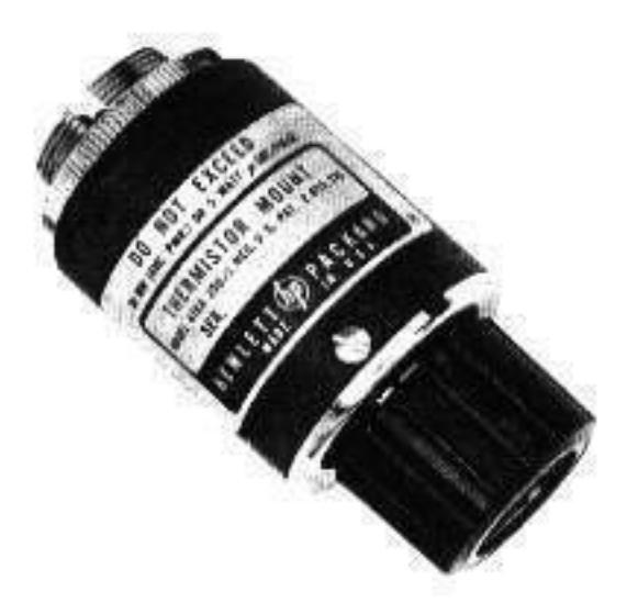
S Model 478A Thermistor Mount
GENERAL INFORMATION
1. INTRODUCTION,
2. The § Model 478A Coaxial Thermistor Mount is designed for use with § Model 431 Power Meters to measure microwave power from 1 µw to 10 mw. Design of the mount minimizes adverse effects from environmental temperature changes during measurement. For increased measurement accuracy, Effective Efficiency and Calibration Factor are measured for each mount, and at selected frequencies across the operating range the results are marked on the label of the instrument (see Paragraph 30). The Model 478A can be used over the 10-Mc to 10-Gc frequency range. Throughout the range, the mount terminates the coaxial input in a 50-ohm impedance, and has an SWR of not more than 1.6 without external tuning.
01204-
3. Each mount contains two series pairs of thermistors, which are matched for cancellation of the effects of drift with amotent temperature change. Thermal stability is accomplished by mounting the leads of all four thermistors on a common thermal conductor to ensure a common thermal environment. This conductor is thermally insulated from the main body of the mount so that thermal noise or shocks applied externally to the mount, such as those from handling the mount manually, cannot significantly penetrate to disturb the thermistors. This thermal immunity enables the thermistors to be used in the measurement of microwave power down to the microwatt region.
Table 1. Specifications
Frequency Range: 10 Mc to 10 Gc.
SWR: 10 to 25 Mc: 1.6, max 25 Mc to 7 Ge: 1.3, max 7 to 10 Ge: 1.5, max
Power Range: 1 uw to 10 mw.
Max Energy per pulse: 10 w-µsec, PRF >1 kc; 5 w-µsec, PRF <1 kc.
Elements: Four permanently installed thermistors.
Operating Resistance: 200 ohms +1%.
Mount Calibration: Calibration Factor and Effective Efficiency furnished at six frequencies between 1 and 10 Gc. Maximum uncertainty of data:
|
Calibration
Factor |
Effective |
431 Power
Range (mw) |
|||
|---|---|---|---|---|---|
| ±1.5% | +2.5% | 10 | |||
| #1.5% | ±2.5% | з | |||
| ±1.5% | 12.5% | 1 | |||
| +1.5% | #2.5% | 0.3 | |||
| ±2% | ±3% | 0.1 | |||
| ±3% | ±4% | 0.03 | |||
| ±4 m | =5% | 0.01 | |||
plus uncertainty of reference standard. * See text for methods of obtaining increased accuracy.
RF Connector: Type N, male.
Bridge Connector: Mates with cable supplied with the P Model 431 type Power Meters.
Dimensions: 2-13/16 in long (72 mm), 1-3/8 in (35 mm) maximum diameter.
Net Weight: 5 oz (140 grams).
*Directly traceable to National Bureau of Standards at those frequencies at which the Bureau offers calibration service.
4. INCOMING INSPECTION.
5. Inspect the Model 478A upon receipt for mechanical damage. Also check it electrically; if the mount was subjected to severe mechanical shock during shipment, the match between the thermistors may be affected. To check thermistor match, proceed as described in Paragraph 51.
6. If any damage is found, inform the carrier and your nearest & Sales and Service Office immediately.
April 1967
00478-90005
07/75/2015785
1501 Page Mill Road, Palo Alto, California, U.S.A., Cable: "HEWPACK" Tel: (415) 326-7000
Europe: 54 Route Des Acacias, Geneva. Switzerland. Cable: "HEWPACKSA" Tel. (022) 42.81.50
OPERATION
- 7. PRECAUTIONS.
- 8, MECHANICAL SHOCK.
9. DO NOT DROP OR SUBJECT TO SEVERE ME-CHANICAL SHOCK. SHOCK MAY DESTROY THE MATCH BETWEEN THERMISTORS AND INCREASE SUSCEPTIBILITY TO DRIFT.
10. BIASING THERMISTORS.
CAUTION: Before connecting the Model 478A to @Model 431 Power Meters, set MOUNT RES switch to 200 obm position. CONNECTING A 200-OHM MOUNT TO A POWER METER SET FOR A 100-OHM MOUNT CAN RESULT IN THERMISTOR DAMAGE.
11. MAXIMUM INPUT.
12. The Model 478A/431 combination responds to the average RF power applied. The maximum signal applied to the thermistor mount should not exceed the limitations for 1) average power, 2) pulse energy, and 3) peak pulse power. Excessive input can permanently damage the Model 478A by altering the match between the RF and compensation thermistors (resulting in excessive drift or zero shift) or cause error in indicated power.
13. AVERAGE POWER. The 478A/431 combination can measure average power up to 10 mw. To measure power in excess of 10 mw, insert a calibrated directional coupler such as one of the ⊕ Model 770 series or 790 series between the mount and the source. UNDER NO CIRCUMSTANCES APPLY MORE THAN 30 MW AVERAGE TO THE MOUNT.
14. PULSE ENERGY AND PEAK POWER. In measuring pulse power, there is a limit on the energy perpulse which may be applied to the mount. For a pulse repetition frequency (PRF) less than 1 kc, energy perpulse can be up to 5 watt-µsec; for a PRF 1 kc and above, up to 10 watt-µsec (for lack of space, only the lower limit is shown on the mount name plate). However, this energy limit applies only to pulses shorter than 250 µsec. In Figure 1, the pulse energy limit is translated into a maximum power-meter reading for any PRF. For pulses in this category, allowable peak power is inversely proportional to pulse width but should never exceed 200 watts.
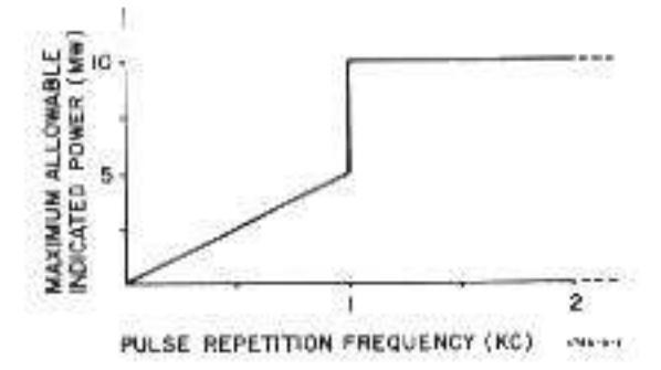
15. For pulses longer than 250 usec, the peak limitation can be expressed in terms of PRF: 10 mw for a PRF below 1 kc, 40 mw for a PRF 1 kc or above, provided 30 mw average is not exceeded. In Figure 2, the peak power limit is translated into power-meter reading versus duty cycle.
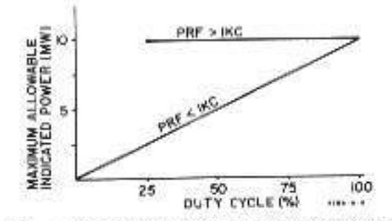
Figure 2. Maximum Power Meter Reading vs Duty Cycle for Pulses Longer than 250 asec
16. Square-wave modulation is a special case of pulse modulation, and maximum power-meter reading versus square-wave frequency is illustrated in Figure 3. This figure also holds for sine-wave modulation.
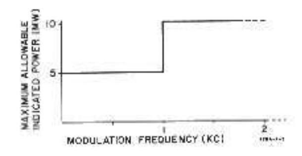
Figure 3. Maximum Power Meter Reading vs Souare and Sine-Wave Frequency
17. In the discussions above, the primary consideration is maximum power or energy. However, for modulation frequencies less than 100 cps, the low repetition frequency itself causes errors in indicated power. These errors may be as large as 2% regardless of range or reading.
18. When RF is switched by pulse-gating (coaxial solid state switches), consideration must be given to RF energy contained in the switching pulse itself. And this energy must be added to actual RF pulse power when estimating the RF power dissipated in the thermistor mount. PIN diode modulators of 3/2 Model 8714A/8716A Modulators and 8614A/8616A Signal Generators, however, are not subject to this consideration because output filtering prevents transmission of modulating signals.
19. DRIFT PRECAUTION.
20. Thermistors are inherently temperaturesensitive devices. A cold thermistor mount connected to awarm piece of equipment, or vice versa, produces rapid drift. FOR MINIMUM DRIFT ON SENSITIVE RANGES, MAKE SURE THAT THE MOUNT AND THE EQUIPMENT CONNECTED TO IT ARE AT NEARLY THE SAME TEMPERATURE BEFORE MAKING A MEASUREMENT.
21. ZERO-SET,
22. It is necessary to electrically zero-set the Model 431 Power Meter before making a power measurement. To preserve the same zero reference throughout the measurement, maintain the same thermal environment when RF power is applied. Two recommended setups for zero-set are presented below:
23. RF POWER TURNED OFF FOR ZERO-SET.
24. There is minimum zero drift when the zero is set with the RF system connected to the thermistor mount and the RF power switched off or greatly attenuated by the generator altenuator. The several methods used in the B signal generators to switch off the RF output are listed in Table 2. After allowing time for the mount to stabilize thermally, follow the steps for zero-set described in the Model 431 Power Moter manual and then turn on the RF source.
25. THERMISTOR MOUNT DISCONNECTED FOR ZERO-SET.
26. When it is inconvenient to turn off the RF power in the RF system, connect the Model 478A mount to the RF system and set RANGE on the Model 431 Power Meter for an approximate midscale reading. When the reading no longer drifts, disconnect the mount from the source, immediately terminate the mount, if necessary, as described in Paragraph 27, and then immediately zero-set the power meter. Immediately reconnect the mount to the RF source for the power measurement.
27. With the Model 478A mount connected to the RF system, the source impedance shunts one of the RF thermistors (see Figure 4); when the Model 478A mount is disconnected, the source impedance is removed. Unless source impedance is high, this variation in impedance affects the RF bridge 10-kc feedback loop in the power meter, and the zero-level setting obtained with the source disconnected is no longer zero for the measurement. This error can be eliminated by terminating the mount in an impedance which approximately matches the generator impedance at 10 kc; the termination should be connected while the mount is disconnected (see Paragraph 26) from the source. For example, if the impedance presented by the RF system to 10 kc is low (1K ohm or less) terminate the thermistor mount in a 50-ohm resistor or a short. On the other hand, if the impedance of the RF system at 10 kc is high (100K ohms or more) leave the thermistor mount unterminated during zero-set

Figure 4. Source Impedance Shunting One RF Thermistor
| hp Generator | Frequency Range | Procedure to Switch Off RF Output |
|---|---|---|
| Model 606 | 50 ke to 65 Me | Increase the generator output attenuation 30 or more do |
|
Model 8614A/8616A
Model 614/616 Model 618/620 |
800 to 2400 Mc/1800 to 4500 Mc
800 to 2100 Mc/1800 to 4200 Mc 3.8 to 7.6 Gc/7 to 11 Gc |
Release RF pushbutton
Set modulation selector to OFF Set modulation selector to OFF |
|
Model 608
Model 682/687 |
10 to 480 Mc/10 to 420 Mc
1 to 2 Gc/12.4 to 18.0 Gc |
Set MOD SELECTOR to PULSE, but do not apply
modulation signal to modulation input terminal |
| Model 612 | 450 to 1230 Mc |
Set MOD SELECTOR to PULSE 2, but do not apply
modulation signal to modulation input terminal |
| Model 690,9690 series | 1 to 40 Gc | Set LINE to STANDBY |
Table 2. Methods of Switching Off RF output of Various hp Signal Generators
01204-9
Note
In the proximity of a high RF field, shield the disconnected thermistor mount from possible stray RF pick-up during the zero-set.
28. Note that some 10-kc bias signal is coupled into the RF transmission system by C2 (Figure 5). If the RF source output impedance at 10 kc is 15K ohms or greater, 10-kc bias voltage is typically 1.3 v RMS and could equal 1.5 v RMS. For an RF source output impedance of 50 ohms at 10 kc, bias signal voltage is typically 5 mv RMS.
29. The presence of this 10-kc bias signal may affect solid state RF sources and RF voltmeter measurements. To minimize or eliminate these effects, use an additional blocking capacitor at the Model 478A or a high-pass filter at the RF source output,
30. MOUNT CALIBRATION DATA.
31. The calibration points imprinted on the label of each 478A allow power measurements to be made with increased accuracy. Values of Calibration Factor and Effective Efficiency are given at six frequencies between 10 Mc and 10 Gc. The mounts are tested on a swept-frequency basis to assure accurate interpolation between calibration points. Calibration Factor and Effective Efficiency values are traceable to the National Bureau of Standards to the extent allowed by the Bureau's calibration facilities.
32. CALIBRATION FACTOR. Calibration Factor is the ratio of substituted audio or DC power in a thermistor mount to the microwave RF power incident upon the mount.
Calibration Factor = PDC Substituted PLwave Incident
33. Calibration Factor is a figure of merit assigned to a thermistor mount to correct for the following sources of error: 1) RF reflected by the mount due to mismatch, 2) RF loss caused by absorption within the mount but not in the detection thermistor elements, and 3) DC-to-microwave power substitution error. Calibration Factor is applied as a correction factor to all measurements made without a tuner. When these factors and thermoelectric effect (refer to Paragraph 38) are taken into consideration, the power indicated is the power that would be delivered by the RF source to the characteristic impedance of the transmission line. The total SWR in the transmission line determines a region of uncertainty about the measured power. This subject is discussed in Application Note 64. available from any Hewlett - Packard Sales and Service Office.
34. EFFECTIVE EFFICIENCY. Effective Efficiency is the ratio of substituted audio or DC power in a thermistor mount to the microwave RF power dissipated within the mount.
Effective Efficiency = PDC Substituted PLwave Dissipated
35. Effective Efficiency corrects for power absorbed in parts of the mount other than the detection thermistor elements and DC-to-microwave power substitution error in the thermistor mount. Effective Efficiency is applied as a correction factor when a tuner is used to match the thermistor mount to the transmission line or RF source. In this case, all of the RF power incident upon the mount is absorbed in the mount. Since all power is absorbed in the mount, measurement uncertainty due to mount SWR is eliminated.
36. CALIBRATION DATA APPLICATION.
37. When the 478A is used with the Model 431C Power Meter, Calibration Factor or Effective Efficiency correction can be made by the setting of a front panel switch. With the proper setting, the 431C compensates for the Calibration Factor or Effective Efficiency of the 478A. If the 478A is used with a power meter other than the 431C, Calibration Factor or Effective Efficiency correction can be made by dividing the measured power by the Calibration Factor or Effective Efficiency value respectively.
38. THERMOELECTRIC EFFECT.
39. Mount calibration uncertainties given in Table 1 include inaccuracies caused by thermoelectric effect error. Calibration Factor uncertainty of ±1.5% and Effective Efficiency uncertainty of ±2.5% can be maintained on the three lowest power ranges of the Model 431-series Power Meters by correcting for the measurement error introduced by thermoelectric effect. An error correction procedure is given in Paragraph 43.
40. A mild thermocouple exists at each point of contact where the connecting wires join to the thermistor elements. Each thermocouple creates a DC voltage. Thus, two thermocouple voltages of opposite relative polarity are formed, one at each junction to each thermistor element.
41. Ideally, each thermocouple voltage would be equal in magnitude so that they cancel with no resultant effect on the accuracy of power measurement. In practice however, each point of contact does not have identical thermocouple characteristics, and in addition, the temperatures at each junction may not be the same. These differences cause an incomplete cancellation of the thermoelectric voltages, resulting in a voltage that causes a thermoelectric effect error. The magnitude of the error is important when making DC substitution measurements on the 0.1 mw, 0.03 mw, and 0.01 mw ranges with one of the Model 431-series Power Meters. On other ranges, the effect is negligible. Maximum error introduced by thermoelectric effect is about 0.3 μw and is typically 0.1 μw on the .01 mw range.
42. THERMOELECTRIC EFFECT ERROR CORRECTION.
43. Use the following technique to correct for thermoelectric effect error.
a. Measure power.
b. Connect an hp Model 8402 Power Meter Calibrator to the power meter DC CALIBRATION AND SUBSTI-TUTION connector.
c. Zero and null power meter.
d. By DC Substitution (refer to procedure in 431 Manual), duplicate power measurement made in step a. Calculate and record substituted power as P1.
e. Reverse connection polarity between the calibrator and power meter.
f. Re-zero and re-null power meter, if necessary.
g. By DC Substitution, duplicate power measurement made in step a. Calculate and record substituted power as P2.
h. Calculate arithmetic mean of the two substitution powers P1 and P2. This mean power includes a correction for thermoelectric effect error.
Power =
OPERATING PRINCIPLES
44. CIRCUIT DESCRIPTION.
45. Two matched series thermistor pairs are mounted on a common thermal conducting block, represented by the shaded rectangle in Figure 5. One pair, marked D for detection, is mounted between the end of a coaxial cable and a cylindrical cavity. These thermistors are exposed to incoming RF power which heats them, lowering their resistances. The other pair, marked C for compensation and situated immediately outside the cavity, is completely ahielded from RF. With the Model 478A attached to a Model 431 Power Meter, the detection thermistors are part of the RF bridge and the compensation thermistors are part of the metering bridge. Since the two pairs of thermistors share the same thermal environment, any charge in temperature which affects the RF bridge simultaneously affects the metering bridge, thereby allowing the power meter circuit to compensate for changes in temperature, and thus to minimize drift.
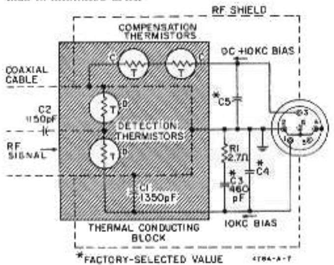
Figure 5. Schematic Diagram Model 478A Thermistor Mount
46. During operation, sufficient amounts of DC and 10-kc bias currents are supplied from the Model 431 Power Meter to heat the thermistors until their resistances are reduced to approximately 200 ohms per series pair. Capacitor C1 offers high impedance to 10 kc, but is practically a short to RF. This causes D to appear series-connected to 10 kc, but parallelconnected to RF. In this manner, D appears to the audio bridge of the Model 431 Power Meter as a 200ohm resistance, but terminates the coastal cable in 50 ohms. Capacitor C2 blocks any DC and audio power that might be present in the incoming signal, and passes only RF power.
47. POWER DETECTION.
48. Under normal operation, the total power supplied to beat thermistor pair D (see Figure 5) consists of: 1) RF signal, 2) 10-kc bias, and 3) heat from the enviroament. The total power supplied to heat thermistor pair C consists of: 1) DC bias, 2) an equal amount of 10-kc bias, and 3) heat from the same environment. As D and C are matched thermally, the total amounts of heat applied to reduce their series resistances equally must be equal. Restating the foregoing algebraically: under normal operation
Ptotal to D"PRF to D"P10 kc to D"Penv heat to D
and
Ptotal to to kc to env heat to C
Since the thermistors are mounted on the same thermal block,
Penv heat to D*Penv heat to C
and since
this leaves
PRF to D"PDC to C
PDC to cis monitored by the Model 431 Power Meter.
MAINTENANCE
49. MECHANICAL SHOCK.
50. The Model 476A is a precision instrument. Avoid dropping or other mechanical shocks. Such shocks can destroy the match between the thermistors,
51. CHECK ON THERMISTOR MATCH.
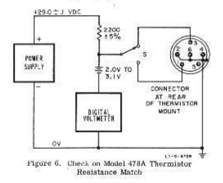
52. Match between the thermistors may be checked by comparing the thermistor resistances under simulated operating conditions. Equipment required is indicated in Figure 6. Make connections to the connector at the
rear of the thermistor mount; pins are shown in Figure 6. Note that the small battery in series with the Model 405 Digital Voltmeter is connected in opposition to the power supply. The value of this bucking voltage should be such that voltmeter resolution down to 0.001 volt is obtained. Take readings with switch S connected to pin 1 and then to pin 3. Thermistor match is satlafactory if the two readings do not differ by more than 0.030 volt. Non-operating mounts with readings as high as 0.150 volt can probably be repaired as outlined in the succeeding paragraphs.
53. REPAIR,
54. Exceeding the CW or pulse power limits of the Model 478A Thermistor Mount may result in damage such that the mount will co longer zero on the Model 431 Power Meter.
55. Before adjusting the mount in any way, make sure that the mount is the cause of the problem. An open or short indication, using the checks in Paragraph 52 or 58, means that the mount is not repairable by the procedure outlined in the following paragraphs. However, the mount may be non-operative, but still repairable. Test for this by using the procedure in Paragraph 52, or by connecting the mount to a Model 431 and cable which are known to be good. A faulty cable will not have continuity through the respective connector pins, or may have poor contact at the mount connector. Poor contact will show up as intermittence or a great deal of noise (visible on the 431 meter) when the cable is gently tlexed near the connector end.
56. To troubleshoot a damaged mount, proceed as follows;
a. Connect mount to Model 431.
| b. Set: | MOUNT | RE | s | 22 | 32 | 2 | 100 | ohm | |
|---|---|---|---|---|---|---|---|---|---|
| RANGE | 4 | 2 | 10 | MW | |||||
| POWER | • | ÷ | a. | 20 | ON. |
c. Rotate ZERO from one limit to the other.
57. Il meter remains pegged upscale, the thermistor elements have been damaged. However, it may be
possible to recompensate the thermistors per Paragrapha 60 and 62 and return the mount to operation; otherwise they must be replaced. In either case, the Effective Efficiency and Calibration Factor data on the nameplate are no longer valid (see Paragraph 69).
53. If meter remains pegged downscale, measure resistance between pins 1 and 2, and pins 3 and 4. The resistance should measure between 1000 and 5000 ohms. An open or aborted reading indicates the need for replacement of the thermistors.
WARNING
Under no conditions should the mount be required to carry a current higher than 14 ma.
59. If the resistance reading is satisfactory, it may be possible to recompensate the mount, and return it to service. The drift with temperature changes will be higher because of the damage to the thermistors, but it will be possible to zero the meter and to make measurements. The Effective Efficiency and Calibration Factor indicated on the tabel will no longer be valid (see Paragraph 69). There are two adjusting screws inside the instrument which permit recompensation within limits. Most instruments with serials lower than 7663 do not have the adjusting screws at the time of manufacture, but are modified if the instrument was sent in for repair after March, 196
60. Refer to Figure 7, and proceed as follows:
- a. Remove the three acrews (A).
- b. Slide instrument out of its cover.
- c. Plug cover into Model 431.
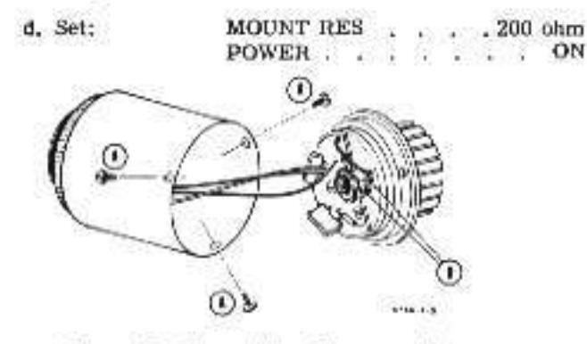
Figure 7. Thermistor Compensation
- 61. If meter is pegged downscale:
- a. Set RANGE to 10 MW.
- b. Set ZERO and VERNIER to mid-range.
- c. Turn screws (B) clockwise, 1/8 turn alternately.
CAUTION
If there is a sudden jump in meter indication when advancing either screw, back off 1/8 turn, and do not advance that screw further. Check resistance as in Paragraph 58. If either screw bottoms, do not apply force. Thermistor replacement (Paragraph 63) is indicated.
d. When meter pointer rises, trim to zero with each adjusting screw
e. Replace cover and three screws (A). The instrument is now operative.
62. If motor is pegged upscale:
a. Set ZERO and VERNIER to mid-range.
b. Set RANGE to highest position which will not peg the meter.
c. Turn one of the sprews (B) counterclockwise to obtain a meter reading half that observed in step o.
d. Turn the other screw (B) counterclockwise to zero the meter. If it is impossible to zero the meter, replace the thermistors (Paragraph 63).
e. Replace cover and three scrows (A). The instrument is now operative.
63. THERMISTOR ASSEMBLY REPLACEMENT PROCEDURE.
Note
After replacement of the thermistor assembly, the Effective Efficiency and Calibration Factor indicated on the label of the mount are no longer valid (see Paragraph 59).
64. The procedure consists of removing the damaged thermistor assembly, the printed circuit assembly, and replacing them with pretested assemblies included in Thermistor Assembly Replacement Kit, & Stock No. 00478-600.
Note
The damaged thermistor assembly should be returned to Hewlett-Packard for credit.
65. The replacement assemblies are pretested at the factory. However, since the operation of the thermistor mount depends on proper installation of the assembly, it may be desirable to check the SWR and efficiency following replacement. The efficiency may be checked by comparing against a known mount. The SWR is checked at 9 Gc and 10 Gc. SWR should be approximately equal at 9 Gc and 10 Gc and should be 1.5 or less.
Note
In the field replaceable thermistor assembly connection of the RF thermistors to the type N center conductor is made by a bellows. If the bellows does not contact the center conductor, SWR will be about 2.0 at 10 Gc. The bellows may be lengthened slightly with a pair of tweezers.
66. The following special tools may be required for the completion of this procedure:
a. One small screwdriver, .070 tip, suitable for removing a 00-90 x 1/8 screw.
b. One pair of lweezers.
Table 3. Parts Furnished in Thermistor Assembly Replacement Kit, ♀ 00478-600
| 1 71 | ||
|---|---|---|
| 1 10 | ermistor Assembly | 478A-95A |
| 1 Et | ched Circuit Board | 478A-85A |
| I Re |
sistor, fixed, composition,
27 ohms ±10%, 1/4 W |
0684-0271 |
| 1 or 2 Ca |
pacitor
a, f
ixed,
lipped mica |
• |
67. REMOVAL PROCEDURE
a. Remove three 2-56 x 3/16 acrews holding Terminal Shield (Figure 9). Move Terminal Shield aside.
CAUTION
Do not break wires connecting printed circuit assembly to receptacle connector.
b. Loosen locknut and remove 5/16-32 set screw from Thermistor Assembly.
c. Disconnect the three wires between the printed circuit assembly and the receptable connector from the printed circuit assembly.
d. In sarly Thermistor Assemblies there is a 00-90 x 1/8 screw used to connect the RF Thermistors to the Type N center conductor. Remove this screw, if present, using small screwdriver and tweezers.
e. Remove the three 2-56 x 5/8 inch acrews holding printed circuit and Thermistor Assemblies to the RF Connector Assembly.
f. Remove printed circuit and Thermistor Assemblies.
g. Remove the three insulator bushings from Thermistor Assembly. This completes the removal of the damaged assembly.
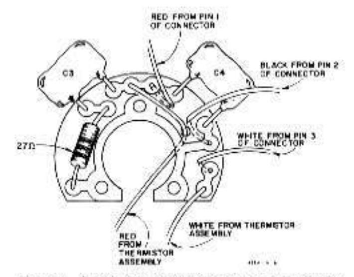
68. INSTALLATION PROCEDURE
a. Referring to Figure 8, connect the three wires from receptacle connector to printed circuit assembly.
Note
For strain relief, the wires should go through the holes indicated and connect from the bottom of the printed circuit assembly.
Install the three insulator bushings in the Thermistor Assembly.
c. Pass the red wire from the Thermistor Assembly through the hole indicated in Figure 8. Do not connect to printed circuit assembly at this time.

d. Mount Thermistor and printed circuil assemblies on RF Connector Assembly. Use three 2-56 x 5/8 inch screws and lockwashers. Screws must be tightened firmly to insure proper bellows contact with the Type N Center Conductor.
lote
Printed circuit assembly must be positioned so it does not cover compensating acrews.
connect red and white wires from Thermistor Assembly to printed circuit assembly.
f. Connect Thermistor Mount to an § Model 431. Check for proper null and zero.
g. If desired, check SWR and efficiency. The Mount SWR has been adjusted at the factory to be about equal at 9 Gc. and 10 Gc. and less than 1.5. The adjustment is made with the 5/16-23 set screw which is secured by a lock nut. The set screw should not be moved unless SWR is being recalibrated. Efficiency may be checked by comparing to a known good mount.
CAUTION
To prevent pulling wires out of terminal connector, secure terminal shield with one 2-56 x 3/16 inch screw while making checks.
h. When any testing or recalibration is completed secure terminal shield with three 2-56 x 3/16 inch screws. This completes the Installation Procedure.
69. RECALIBRATION. If recalibration of the mount is desired, the instrument may be sent to the factory for repair and recalibration. Any Hewlett-Packard Sales and Service Office will arrange for such repair.

Figure 9. Model 478A Thermistor Mount Assembly
CERTIFICATION
The Hewlett-Packard Company certifies that this instrument was thoroughly tested and inspected and jound to meet its published specifications when it was shipped from the factory. The Hewlett-Packard Company further certifies that its calibration measurements are traceable to the U.S. National Bureau of Standards to the extent allowed by the Bureau's calibration facility.
WARRANTY AND ASSISTANCE
All Hewlett-Packard products are warranted against defects in materials and workmanship. This warranty applies for one year from the date of delivery, or, in the case of certain major components listed in the operating manual, for the specified period. We will repair or replace products which prove to be defective during the warranty period. No other warranty is expressed or implied. We are not liable for consequential damages.
For any assistance contact your nearest Hewlett-Packard Sales and Service Office.


 Loading...