

Page 1

HP
This vintage Hewlett Packard document was
preserved and distributed by
Archive
vvwvv.
Please visit us on the web
Scanned by on-line curator: Tony Gerbic
h parc hive.com
!
**
For
FREE
Distribution Only
***
Page 2
460BR
FAST PULSE AMPLIFIER
OPERATING
AND
SERVICING
MANUAL
Page 3
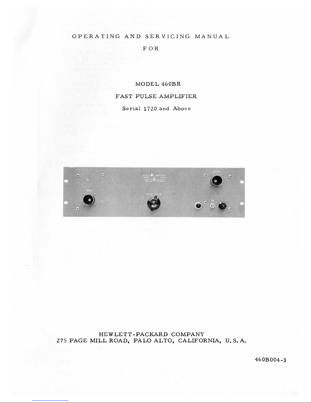
OPERATING AND SERVICING MANUAL
FOR
MODEL
FAST
r
5
J
PULSE
Serial
1720
46OBR
AMPLIFIER
and Above
HE
275
PAGE MILL
WLETT -PACURD COMPANY
ROAD,
PAL0 ALTO, CALIFORNIA,
U.
S.
A.
46
OB
004-3
Page 4
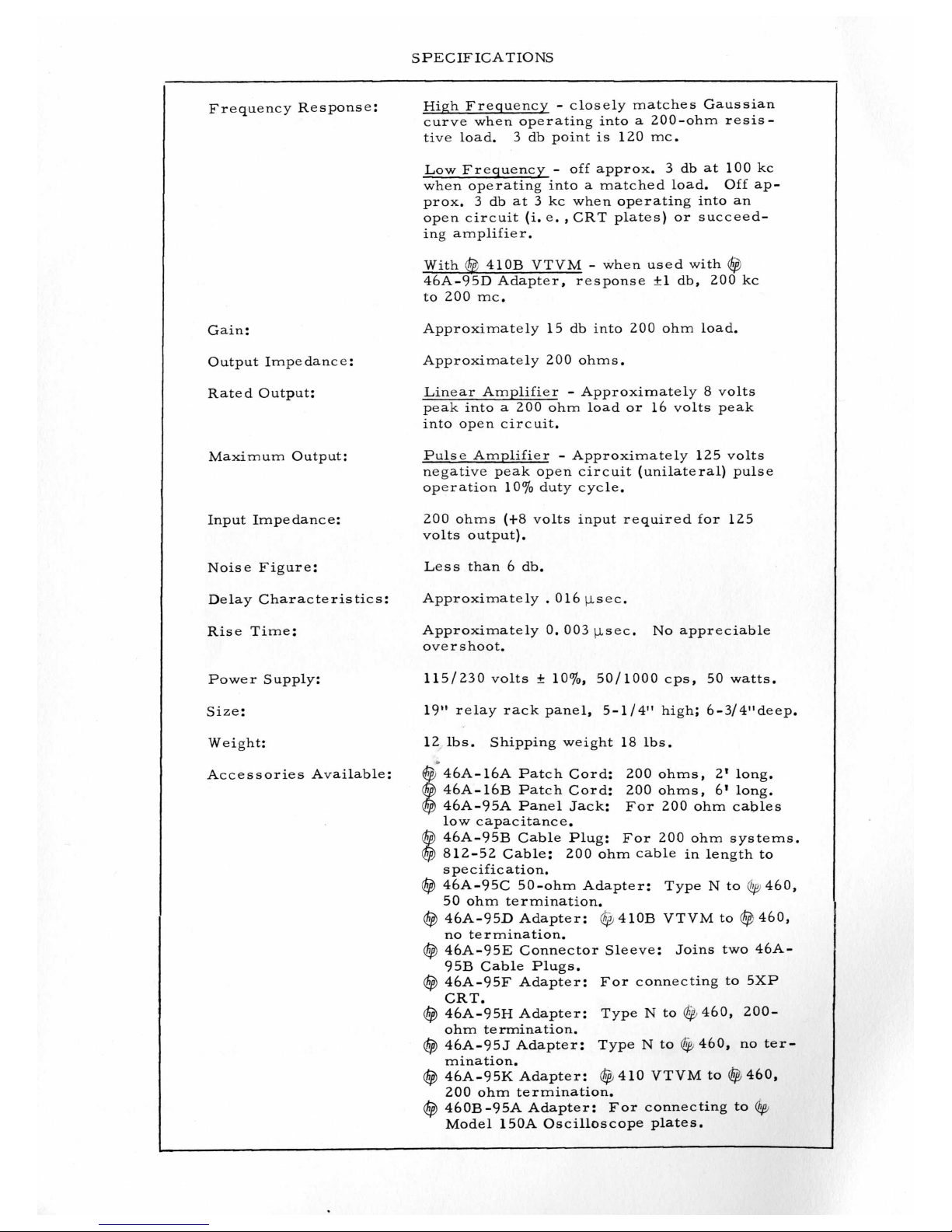
SPECIFICATIONS
Frequency Res pons e
Gain:
Output Impedance:
Rated Output:
Maximum Output:
Input Impedance:
:
High Frequency
curve when operating into
tive load. 3 db point
Low Frequency
when operating into
prox.
open circuit
ing amplifier.
With
46A-95D Adapter, response +1 db,
to
Approximately 15 db into
Approximately
Linear Amplifier
peak into
into open circuit.
Pulse Amplifier
negative peak open circuit (unilateral) pulse
operation 10% duty cycle.
200
volts output).
3
db at 3 kc when operating into an
@
410B VTVM - when used with
200
mc.
a
ohms (t8 volts input required for 125
-
closely matches Gaussian
a
200-ohm resis-
is
120 mc.
-
off approx. 3 db at 100 kc
a
matched load.
(i.
e., CRT plates) or succeed-
200
ohm load.
200
ohms.
-
Approximately 8 volts
200
ohm load or 16 volts peak
-
Approximately 125 volts
Off ap-
@
200
kc
Noise Figure:
Delay Characteristics:
Rise Time:
Power Supply:
Size:
Weight:
Accessories Available:
6
Less than
Approximately
Approximately 0.003 psec.
overs hoot.
19" relay rack panel, 5-1/4" high; 6-3/4"deep.
12
lbs. Shipping weight 18 lbs.
@<46A-l6A Patch Cord:
@
46A-16B Patch Cord:
@
46A-95A Panel Jack: For
low capacitance.
@
46A-95B Cable Plug: For
@
812-52 Cable:
specific ation.
($3
46A-95C 50-ohm Adapter: Type N to Op460,
50 ohm termination.
@
46A-95D Adapter: @410B VTVM to @460,
no termination.
@
46A-95E Connector Sleeve: Joins two 46A95B Cable Plugs.
@
46A-95F Adapter: For connecting to 5XP
CRT.
($3
46A-95H Adapter: Type N to @460,
ohm termination.
@
46A-95J Adapter: Type N to ($460, no termination.
@
46A-95K Adapter: @410 VTVM to ($5460,
200
@
460B-95A Adapter: For connecting to
Model 150A Oscilloscope plates.
db.
.
016 psec.
200
ohm termination.
No
appreciable
200
ohms,
200
ohms,
200
200
ohm cable in length to
2'
long.
6'
long.
ohm cables
ohm systems.
200-
fp
Page 5
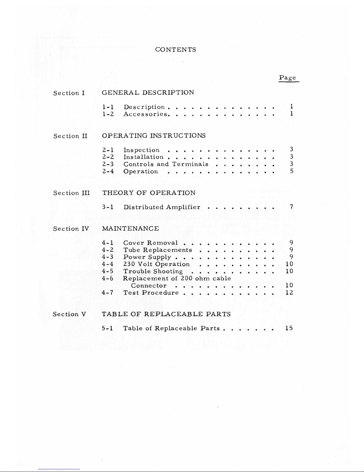
CONTENTS
Page
Section
Section
Section
Section
I
I1
I11
IV
GENERAL DESCRIPTION
1-1
1-2
OPERATING INSTRUCTIONS
2-1
2-2
2-3 Controls and Terminals
2-4 Operation
THEORY
3-1
MAINTENANCE
4-1 Cover Removal
4-2 Tube Replacements
4-3
4-4 230
4-5
4-6
4-7 Test Procedure
Description
Accessories.
Inspection
Installation
..............
.............
..............
..............
..............
OF
OPERATION
Distributed Amplifier
............
Power Supply
Volt
Operation
Trouble Shooting
Replacement
Connector
.............
of
200 ohm cable
.............
............
...........
........
.........
..........
..........
1
1
3
3
3
5
7
9
9
9
10
10
10
12
Section
V
TABLE
5-1 Table
OF
REPLACEABLE PARTS
of
Replaceable Parts
.......
15
Page 6
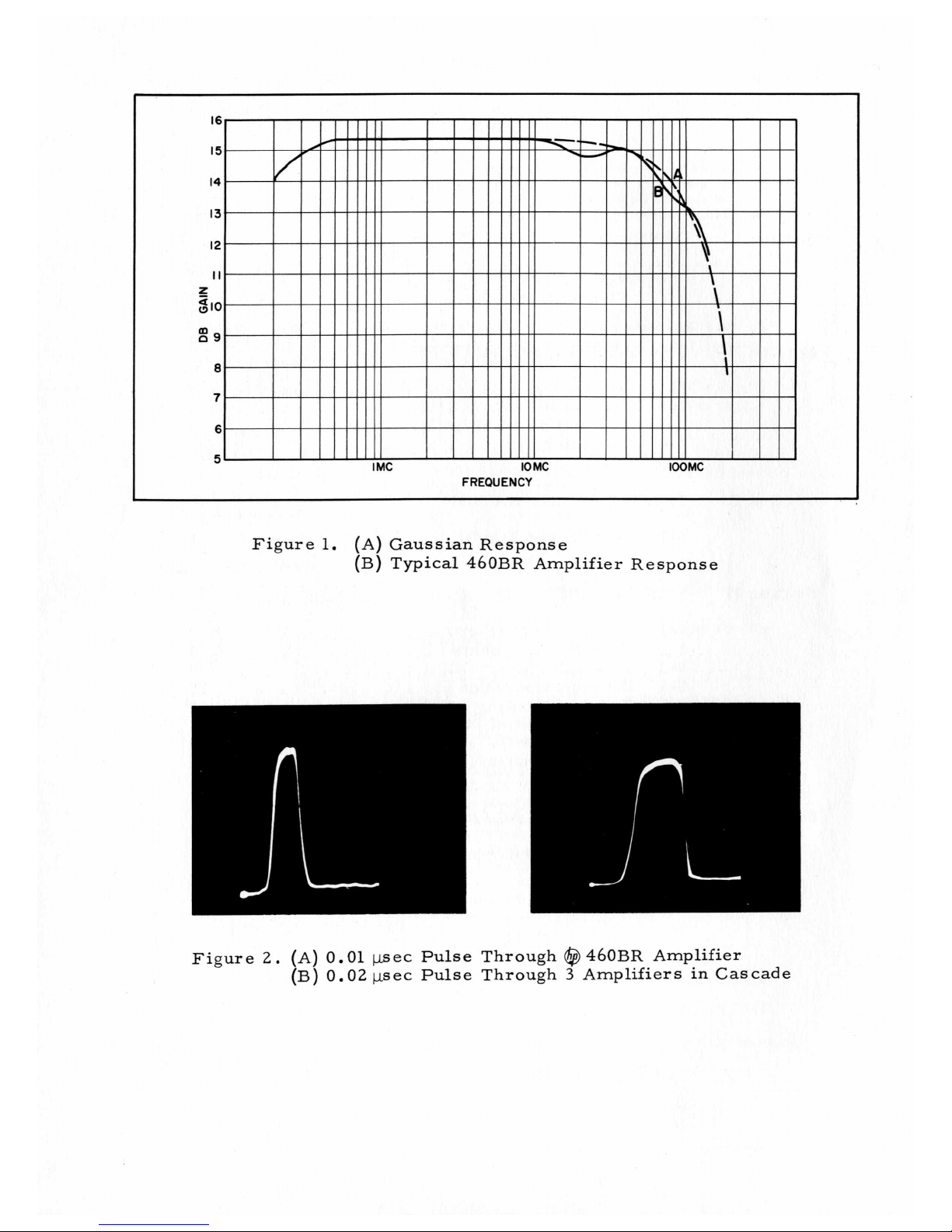
Figure
1.
(A)
Gaussian Response
(B) Typical 460BR Amplifier Response
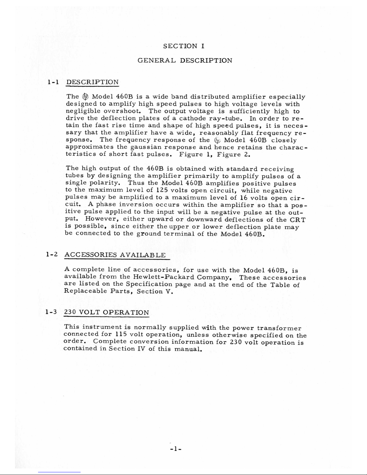
Figure
2.
(A)
(B)
0.01 psec Pulse Through
0.02
psec
Pulse Through
@
460BR Amplifier
3
Amplifiers in Cascade
Page 7
SECTION
GENERAL DESCRIPTION
I
1-1
1-2
DESCRIPTION
@
The
designed to amplify high speed pulses to high voltage levels with
negligible overshoot. The output voltage
drive the deflection plates of
tain the fast rise time and shape of high speed pulses, it
sary that the amplifier have
sponse.
approximates the gaussian response and hence retains the characteristics of short fast pulses. Figure
The high output of the 460B
tubes by designing the amplifier primarily to amplify pulses
single polarity.
to the maximum level of 125 volts open circuit, while negative
pulses may be amplified to
cuit. A phase inversion occurs within the amplifier
itive pulse applied to the input will be
put. However, either upward or downward deflections of the CRT
is
be connected to the ground terminal of the Model 46OB.
ACCESSORIES AVAILABLE
Model 460B
The frequency response of the
possible, since either the upper or lower deflection plate may
is
a
wide band distributed amplifier especially
is
sufficiently high to
a
cathode ray-tube.
a
wide, reasonably flat frequency re=
@
Model 460B closely
1,
Figure
is
obtained with standard receiving
Thus the Model 460B amplifies positive pulses
a
maximum level of
a
negative pulse at the out-
In order to re=
is
2.
16
volts open cir-
so
that a pos-
neces-
of
a
A complete line
available from the Hewlett-Packard Company,
are listed on the Specification page and
Replaceable Parts, Section
1-3 230 VOLT OPERATION
This instrument
connected for 115 volt operation, unless otherwise specified on the
order.
contained in Section
Complete conversion information for 230 volt operation
of
accessories, for use with the Model 460B,
is
normally supplied with the power transformer
IV
V.
of this manual.
at
the end of the Table of
These accessories
is
is
-1
-
Page 8
SECTION
OPERATING INSTRUCTIONS
2-1
INSPECTION
This instrument has been thoroughly tested and inspected before
being shipped and is ready for use when received.
After the instrument is unpacked,
for damage received in transit.
follow the procedure outlined in the "Claim for Damage in Ship-
ment" page at the back of this instruction manual.
2-2
INSTALLATION
I1
it
should be carefully inspected
If any shipping damage
is
found,
No special precautions are necessary except, when several
Amplifiers are to be used in cascade,
mon ground,
output must be kept away from the input to avoid the possibility of
feedback.
2-3
CONTROLS
ON
This toggle switch controls the a-c power supplied to the instru-
ment from the power line.
LINEAR, PULSE
This rotary switch selects the type of amplification desired.
i.
e. : mounted in a relay rack, and the high-voltage
AND
TERMINALS
they must have
a
FUSE
The fuseholder, located on the panel, contains the power
line fuse.
fied in the Table of Replaceable Parts, Section
POWER CABLE
The three-conductor power cable supplied with this instrument
is terminated in
third contact
blade connector which grounds the instrument chassis when used
Replacement fuses should be
a
polarized three-prong male connector. The
is
an offset, round pin added to a standard two-
of
the type speci-
V.
460
good com-
-3
-
Page 9

h
k
3
0
rr
0
z
w
a
0
v
I-
3
a
I-
3
0
cn
5
0
>
Y
a
W
a
PEAK
VOLTS
INPUT
Figure
.25
V
.25V
_I
3.
460
B
LINEAR
460
A
Linearity Characteristics
4608
LINEAR PULSE
2
.H
460A
1
-
of
460BR
460
460
PULSE
Amplifier
B
B
.25V 2.5V
460
A
Figure
4.
460
LINEAR
i
Cascading
8
460
Amplifiers
460
B
PULSE
Page 10

with an appropriate receptacle.
a
to connect this plug to
is
the adapter
a
short wire. This ground lead should then be connected to
a
suitable ground for the protection of operating personnel.
used, the ground connection
standard two contact system.
An adapter may be used
is
brought out on
INPUT AND OUTPUT
The input and output jacks on the control panel, require special
200-ohm connectors and cables.
2
-4 OPERATION
(See paragraph
Connect the Model 460B to the power line, turn on the power
switch and the instrument
is
in operation.
When
1-2).
To use
as a linear amplifier to amplify sine waves, etc. , or
pulses of either polarity, set the LINEAR-PULSE switch to the
LINEAR position.
position the output
or
8
volts peak into a 200-ohm load.
a
phase reversal between input and output
positive input pulse appears in the output
When the LINEAR-PULSE switch
is
limited to
16
volts peak into an open circuit
It
must be remembered that
is
present and that
as a negative pulse.
To realize the full output capabilities of the Model 46OB,
LINEAR-PULSE switch must be in the PULSE position and
8
tive pulse of about
volts peak be supplied to the input.
is
in this
the
a
a
posi-
In the PULSE position of the LINEAR-PULSE switch the amplifier
tubes are operated at higher than normal supply voltages.
grid bias
Under these
is
increased to keep tube dissipation within ratings.
conditions
(1-8
volt input) the rated tube dissipation
The
is
reached with a duty cycle of 10%. Lower driving voltages will
allow proportionally higher duty cycles, but the output voltage
will be lower.
See Figure
3.
In order to supply this 8-volt positive pulse to a Model 460B, the
units may be cascaded or used with one or more Model 46OA
Wide Band Amplifiers,
see Figure 4.
460 amplifiers, consideration must be given to the polarity
well
as
the amplitude of the pulse to be amplified. For maximum
In
general, when cascading
as
deflection, the set-up must be arranged so that the input to the
last 460BR amplifier is positive and of approximately 8 volts peak
amplitude. This
put pulse.
Hence, an additional 460B can be used when necessary
is
easily done because the 460BR inverts
the
in-
to invert pulse polarity. In most applications an input of about 4
is
volts
sufficient to give satisfactory deflection of a cathode-ray
tube. Certain precautions must be taken when cascading several
460
Amplifiers, see Paragraph 2-2, INSTALLATION.
-5-
Page 11

Page 12

SECTION
111
THEORY
3-1
DISTRIBUTED
The extremely rapid rise time of the
use of the distributed amplifier;* the operation of which is explained
as
followsa See Figure
In
the distributed amplifier, the tubes are connected
vals between two artificial transmission lines that have equal propagation velocities. A signal applied to the input terminals passes
down the grid line and appears on each grid in turn.
plate signal currents flow in the plate line, half in one direction
and half in the other.
tube to the output are the same length in terms
traversed, the individual plate signal currents
output termination in phase, thus adding together in the load. The
plate signal currents flowing in the reverse direction are absorbed
without reflection in the reverse plate line termination.
put voltage of
-
nZp
Eo
plate signal current, and
-rip where n
-
AMPLIFIER
5.
Since the paths from the input through any
a
distributed amplifier
is
the number of tubes in the stage, ip
Zp
OF
OPERATION
460B
is
is
the plate line impedance.
is obtained through the
of
will
given by the relation
at
fixed inter-
The resulting
line sections
arrive
The
at
the
out-
is
the
The number of tubes that can be used in
by grid loading which occurs
increased input conductance of the amplifier tubes. This effect
reduces the high frequency gain and in effect restricts the fre-
quency range of the amplifier.
When amplifiers are cascaded, the rise time
that of
In
RC
*
a
single unit in accordance with the relation:
T=
where:
addition to the rise time of the amplifiers, the rise time
combination formed by the capacitance of the deflection gates
Ginzton, Hewlett, et
IRE,
Vola
36,
August,
112
all,
at
high frequencies because of the
T
is
total rise time
t
is
the rise time of a single
(2mbXlO-9
unit
n
is
the number of
Distributed Amplification, Proc.
1948
a
single stage is limited
will
be greater than
sec.)
460
units.
of
the
Page 13

and the internal resistance
consider e d.
In
any case, the total rise time of any number
in conjunction with any load may be found approximately by the
following relation:
where:
of
the
460B (200
n
=
t
C
T
ohms) shouldbe
of
460
Amplifiers
number
rise time
2.6XlO-9
total shunt capacitance on the
output of the
total rise time.
of
460
of
sec.
one
460
Amplifiers
460
=
in farads.
-8-
Page 14

SECTION
MAINTENANCE
IV
4-1
4-2
4-3
COVER REMOVAL
You will be able to slide the one-piece cover off the instrument
after removing the four screws in the rear of the cover.
TUBE REPLACEMENTS
In many cases instrument malfunction can be corrected by replacing
a
weak or defective tube.
ment or component replacement, check the tubes. Adjustments
made in an attempt to compensate for
complicate the repair problem.
It
is
good practice to check tubes by substitution rather than by
a
the use of
checker" can be misleading. Mark original tubes to insure return to the same socket.
defective
Any tube with corresponding standard EEIA (JEDEC) characteristics
can be used
POWER SUPPLY
"tube checkert1. The results obtained from the "tube
as
a
replacement.
Before making any internal adjust-
a
defective tube
Replace only tubes proved to be weak or
will
often
The 460B power supply delivers two output voltages depending
upon the setting of PULSE-LINEAR switch S1.
With S1 in the PULSE position, selenium rectifiers CR-1 and CR-2
are connected in
between ground and the common junction of capacitor C22,
choke L28, and fuse
270
&
be
ing instrument performance.
When switch S1
CR-2 are connected in parallel as half-wave rectifiers. The dc
output voltage between ground and the point described above
be 110 volts when the line voltage
age
is
Low power supply voltages are generally caused by weak selenium
rectifiers, leaky filter capacitors, shorted tubes or off-value re-
s
is
tor
15 volts.
again not critical.
s
.
a
voltage doubler circuit. The dc output voltage
F2
with the line voltage set to 115 volts will
Ripple voltage can be quite high without affect-
is
in the LINEAR position,
is
set to
rectifiers CR-1 and
115
volts. Ripple volt-
filter
will
-9-
Page 15

4-4 230 VOLT
The
@
from
ment is normally supplied with the dual primary windings of the
power transformer connected in parallel for 115 volt operation.
To convert for 230 volt operation,
in series as shown on the schematic diagram. The line fuse
must also be changed from
blow,
4-5 TROUBLE SHOOTING
a
OPERATION
Model 460B can be quickly and easily converted to operate
nominal 230 volt
50/1000
0.8
amp slow-blow to 0.4 amp slow-
cps power source.
reconnect the primary windings
The instru-
F1
Low gain, low output, and impaired frequency response are
directly related to tube mutual conductance and power supply output voltage.
pear, the power supply output voltages should be checked (para.
4-3) and the tubes should be checked (para.
Impaired frequency response, low gain, and/or excessive hum
can also be caused by open or shorted coils and by defective ter-
minating res is tors or screen resistor
If
Bt
fuse
5654 tube,
the appropriate screen resistor and resistor R1 for possible damage.
Resistor R1
parallel. Any one of these resistors could open without greatly
affecting the ope rating voltage
The cans of electrolytic capacitors C22, C23, and C24 are insu-
lated from the chassis.
chassis the bias voltage
normally not more than about
sonnel, but tube damage
Consequently, should any of the above symptoms ap-
4-2).
s.
F2
blows,
If
a 5654 tube
is
made up of five
look for
If
will
cm
a
Bt short,
was
responsible for the blown fuse,
980
ohms resistors connected in
s
,
these capacitors are shorted to the
also be shorted.
10
volts and
result
if
loss of bias, or
The bias voltage
is
not dangerous to per-
this voltage is removed,
all
a
shorted
check
is
4-6
REPLACEMENT
Cut
200
1,
a
point where shielding and outer insulation are even with
the end of
cable length to tip of banana plug
shorter than trimmed cable length.
ohm cable to length desired,
OF
200
OHM CABLE CONNECTOR
a
center canductor support bead.
will
-10-
Trim end of cable to
After assembly,
be approximately 1/4"
Page 16

REAR RETAINER CAP
"0"
RING (432-40) CONICAL WASHER (46A-76K)
REAR PLUG BODY BANANA PLUG
(125-33
1
CTIONS)
L
d
t
OUTER INSULATION CENTER CONDUCTOR FRONT PLUG ASSEWBLY
Fig.
Remove outer cable insulation for a distance of
2.
cable end.
3,
Remove three support beads from center conductor.
do this, upset shielding just enough to release beads.
4.
Slide the following parts over the cable shielding in order
given: rear retainer cap, large washer(s), rubber
ring. Either one or two washers are included with the
connector parts
134 washers supplied. Purpose of additional washer
given in step9
5. Slide rear plug body over shielding. Hold rear plug body
against end of outer insulation and cut off shielding 3/16"
from beveled end of rear plug body.
6
Exploded View of the 46A-95B Assembly
at
the factory.
Use
all
of the large 512=
.
(46A
-
2"
76C)
from
To
l'O1r
is
J
6.
Fan shielding out and bend back over rear plug body.
Trim off any shield wire protruding beyond beveled edge.
7.
Place conical washer over shielding with
end of plug.
8.
Insert center conductor through hole in center of front
plug assembly, slide assembly back over conical washer.
Thread rear retainer cap on front plug assembly.
must be firmly tightened
so
that
41-
it
cannot be rotated on
flat
side toward
Plug
Page 17

end of cable,
9.
Measure distance between front edge of rear retainer cap
and front edge of front plug assembly,
not be less than 31/32",
in step d will increase this distance,
10,
Wrap and solder the center conductor to the base of the
banana plug.
tight when connecting to banana plug,
11,
Resistance between outer connectors must be less than one
ohm,
than one ohm,
center connectors must be greater
4-7 TEST PROCEDURE
Resistance between center connectors must be less
is
The use of strap wrenches
Additional washers installed
Do
not pull center conductor excessively
Resistance between outer connectors and
than
recommended,
This distance must
500
megohms.
as
Testing of the 46OB is
needed. However, anyone with the necessary equipment for making the several somewhat complex test set-ups can complete the
procedure.
will be required.
Signal Sources
Voltmeters
Oscilloscope
Attenuators
Miscellaneous
The complete Test Procedure
a
Service Note.
Service Notes
to supply you with copies on request.
Your local
specially trained personnel to assist you with any engineering, ap-
plication, test, or repair problems you may have with
The following
.
. .
Perhaps your most convenient source for these
is
your local
@
Representatiye' also maintains complete facilities and
a
long tedious procedure, and
@
,
.
,
Models 212A, 608C, and 65OA.
. . .
,
.
Models
.
. . , . . . .
.
. .
. . . .
@
is
not often
instruments or their equivalent
410B
.
Models 355Aand 355B.
. , . .
is
available from the
Representative who will be pleased
and 400D/H/L,
, ,
Model 15OA.
Cable Adapters
@
Factory
@
Instruments.
as
-12-
Page 18

Figure
7.
Top View of @Model 460B
Fast
Pulse Amplifier
Figure
8,
Bottom View of
@
Model 460B
-
13-
Fast
Pulse Amplifier
Page 19

f"
Q'
0
-
14-
Page 20

SECTION
V
TABLE
OF
REPLACEABLE PARTS
NOTE
Any changes in the Table of Replaceable Parts will be
listed on a Production Change sheet at the front of this
manual.
When ordering parts from the factory always include
the following information:
Instrument model number
Serial number
-hp- stock number of part
Description of part
Page 21

460B
TABLE OF REPLACEABLE PARTS
CIRCUF
REF.
C1 thruC4
c5
C6 thru ClS
c
20
c21
C22,23,24
C25 thru
c37
CRl, 2
F1
DESCRIPTION,
C apac i to
Capacitor: fixed, ceramic disc,
Same
Same
Capacitor
Capacitor: fixed, electrolytic
Capacitor: fixed, titanium dioxide,
Rectifier, metallic
Fuse, cartridge:
Fuse, cartridge: 0.4 amp, for 230V
r
:
.Ol
pf
.02
v
f
as
C1
as
C5
:
50
1~.
f
tol.
40pf, 450 vdcw
2.2ppf
operation,
ope ration,
MFR.
fixe d, c e rami c
tol.
-O%,
tol.
-0%
fixed, electrolytic
-1070
+lo%,
s
low-blow
s
low -b low
*
Ba
tlOO%,
+loo%,
t2OO70,
500
vdcw
Q.
8 amp, for 115V
MFR. DESIGNATION
,
1000 vdcw CC*
600
vdcw Radio
Material Corp.
,
50
vdcw
,
X*
cc*
DD*
AA*
T*
@
STOCE
NO.
15-43
15-85
18-50
18-40HP
15-52
212-73
211-57
211-56
-
#
18
2
1
3
13
2
1
F2
t1
J1, 52
L1
L2 thru L7
L8 thru L14
Ll5thru 20
L21 thru 27
L28
?I
t1
t2
Fuse, cartridge: 1/4 amp,
regular type 3AG
Lamp, incandescent: 6-8V,
.15 amp, #47
Jack, panel
See R2
Coil Assembly
Coil Assembly
Coil Assembly
Coil Assembly
Reactor: 6H
Cable, power Elec. Cords Co.
Resistor: fixed, precision, 980 ohms,
includes
capacitors HP*
Resistor: fixed, deposited carbon,
195 ohms
@
125 ma, 240 ohms
5
resistors and 4.01 p f
+l%,
1/8 W (includes L1)
T*
N*
HP*
HP*
HP*
HP*
HP*
HP*
HP*
211-6
!11-47
C6A-76
460B-95E
460B -95D
460B-95B
460B-95C
911-47
612-56
460B-67
160B-60
1
1
2
1
1
1
1
1
1
1
1
'
See
It
List
of
Manufacturers Code Letters
#
Total quantity used in the instrument.
For
Replaceable
-16-
Parts
Tablett
.
-
Page 22

460B
TABLE OF REPLACEABLE PARTS
CIRCUrr
REF.
R3 thru
R15,
R16
R17
R18
19
R
R20
R21
R22
s1
52
T1
V1
thru Vl?
DESCRIPTION, MFR.
Res
is
tor: fixed, composition,
12 ohms
Re
s
is
t o r
195 ohms
Resistor: fixed, composition,
5600 ohms
Resistor: fixed, composition,
120 ohms
Res
is
tor: fixed, composition,
18 ohms
Resistor: fixed, composition,
33 ohms
Same
as
Same
as
Switch, rotary
Switch, toggle: SPST
Transformer, power
Tube, electron: 5654
+lo%,
:
fixe d, de po
+1%,
+lo%,
+lo%,
+lO70,
+lo%,
R19
R3
*
1/2
W
s
i
te d carbon,
1/8
W
1/2
2
W
1
W
1
W
&
MFR. DESIGNATION
B*
NN*
W
B*
B*
B*
B*
HP*
IP
HP*
zz*
@
STOCH
NO.
~ ~~
23-12
30-195
23-5600
25-120
24-18
24-33
310-86
310-11
310-133
Z12 -5654
-
#
14
1
1
1
2
1
1
1
1
13
MISCELLANEOUS
Adapter, type
termination
Adapter, for
@
460, no termination
Adapter, for 5XP-CRT
Adapter, for Tektronix 511
Adapter, type llN1l to @460, 200 ohm
termination
Adapter, type llN1* to ($460, no
termination
Adapter,
of @460, 200 ohm termination
Adapter, 200 ohm cable to
deflection plates
Note: for 150's below serial
800,
l1Nt1
to @ 460,
@
410B to output of
@
410A/B ac probe to output
also order 150A-95P
@
50
150A
ohm
HP*
HP*
HP*
HP*
HP*
HP*
HP*
HP*
i6A-95C
i6A-95D
L6A-95F
C6A-95G
C6A-95H
C6A-95J
r6A-9 5K
:60B
-9
5A
:
See lvLisl
If
Manufacturers Code Letters
Total quantity used in the instrument.
For
Replaceable
-17-
Pa
8
Table"
.
Page 23

460B
TABLE OF REPLACEABLE PARTS
CIRCUIT
REF.
DESCRIPTION, MFR.
Cable, plug, for
Connector sleeve, joins two 46A-95B
cable plugs
Deflection plate terminal board for
@
150A with serial numbers below
800
when using Adapter 460B-95A
F
useholder
Jack, panel assembly, for
connector
-
Knob: PULSE
Patch cord,
Patch cord, 6 feet,
Pilot Lamp Assembly
Retainer plate for panel jack
LINEAR
2
feet, 200 ohm cable
200
ohm cable
200
*
&
MFR. DESIGNATION
200
ohm
ohm cable
HP*
HP*
HP*
T*
HP*
HP*
HP*
HP*
IP
HP*
@
STOCE
NO.
~~ ~~
46A-95B
46A-95E
150A-95P
140-16
46A-95A
G-74N
46A-16A
46A-16B
145-2
46A- 7 6A-
#
-
2
1
1
1
See
1t
List
of
Manufacturers Code Letters
#
Total quantity used
in
the instrument.
For
Replaceable
-18-
Parts
Table"
.
Page 24

DESIGNATE
TO
THE
MANUFACTURERS
CODE
LETTER
A
B
C
D
E
F
G
H
HP
I
J
K
L
M
N
0
P
Q
R
S
T
U
V
W
X
Y
Z
AA
BB
cc
DD
EE
FF
GG
HH
II
JJ
KK
LL
MM
NN
00
PP
QQ
RR
ss
TT
uu
vv
ww
xx
YY
zz
AB
AC
AD
AE
AF
AG
AH
AI
AJ
MAN U FACTU RER
Aerovox Corp.
Allen-Bradley
Co.
Amperite Co.
Arrow,
Hart
&
Hegemon
Bussman Manufacturing
Co.
Carborundum Co.
Centrala
Cinch-Jones Mfg.
Hewlett-Packard
Clarostat
Cornell
Hi-Q
Erie
b
Co.
Mfg.
Co.
Dubilier
Elec.
Division
of
Aerovox
Resistor Corp.
Co.
Co.
Fed. Telephone & Radio Corp.
General
General
Girard-Hop
Industrial Products
International
Electric
Co.
Electric Supply Corp.
kins
Co.
Resistance
Co.
Lectrohm Inc.
Littlefuse
Maquire Industries
Inc.
Inc.
Micamold Radio Corp.
Oak
Manufacturing
P.
R.
Mallory
Radio Corp.
Sangamo
Sarkes
Electric
Tanian
Signal Indicator
Sprague
Electric
Stackpole Carbon
Sylvania
Western
Electric
Electric
Wilkor Products,
Co.,
of
America
Co.
Co.
Products
Co.
Inc.
Co.
Inc.
Co.
Co.
Co.
Amphenol
Dial Light
Leecraft Manufacturing
Switchcraft,
Gremar
Co.
of
America
Inc.
Manufacturing
Co.
Co.
Carad Corp.
Electra
Manufacturing
Acro Manufacturing
Alliance Manufacturing
Arc0
Electronics,
Co.
co.
CO.
Inc.
Astron Corp.
Axel Brothers
Inc.
Belden Manufacturing Co.
Bird
Electronics
Barber
Colman
Bud Radio
Allen D. Cardwell Mfg.
Corp.
Co.
Inc.
Co.
Cinema Engineering Co.
Any brand tube meeting
RETMA standards.
Corning
Dale Products,
The Drake Mfg.
Elco
Thomas A. Edison,
Hugh
Glass
Corp.
H.
Eby
Works
Inc.
Co.
Co.
Inc.
Fansteel Metallurgical Corp.
General
The Gudeman
Ceramics & Steatite
Co.
Corp.
ADDRESS
New
Bedford, Mass.
Milwaukee
New York,
N.
4,
Wis.
Y.
Hartford, Conn.
St.
Louis,
Mo.
Niagara Falls,
Milwaukee
Chicago
Palo Alto,
Dover,
N.
I,
Wis.
24,
111.
Calif.
N.
H.
South Plainfield,
Olean,
N.
Y.
Erie
6,
Pa.
Clifton,
N.
J.
Schenectady
Son
Francisco,
Oakland,
5,
Calif.
Calif.
Danbury, Conn.
Philadelphia
Chicago
Des
20,
Plaines,
8,
111.
111.
Pa.
Greenwich, Conn.
Brooklyn
Chicago
37,
10,
N.
111.
Y.
Indianapolis, Ind.
Harrison,
Marion,
111.
N.
J.
Bloomington, Ind.
Brooklyn
North Adams,
St.
Warren,
New
Marys,
York
37,
Pa.
5,
Pa.
N.
N.
Y.
Mass.
Cleveland, Ohio
Chicago
Brooklyn
New
Chicago
Wakefield,
Redwood
Kansas City,
Columbus
York,
50,
37,
22,
City,
N.
N.
Mass.
16,
111.
Y.
Y.
111.
Calif.
Mo.
Ohio
Alliance, Ohio
New
York
13,
N.
East
Newark,
N.
Long Island City,
Chicago
Cleveland
Rockford,
Cleveland
Plahville,
44,
111.
3,
Conn.
111.
14,
Ohio
Ohio
Burbank, Calif.
Corning,
N.
Y.
Columbus, Neb.
Chicago
Philadelphia
Philadelphia
West Orange,
22,
111.
24,
44,
N.
North Chicago,
Keasbey,
Sunnyvale,
N.
J.
Calif.
Y.
N.
N.
Y.
Y.
J.
N.
Pa.
Pa.
J.
111.
CODE
LETTER
J.
Y.
Y.
MANUFACTURER
AK
Hammerlund Mfg. Co.,
Industrial Condenser Corp.
AL
AM
lnsuline Corp.
AN
Jennings Radio Mfg. Corp.
E.
A0
AP
AQ
AR
AS
AT
AU
AV
AW
AX
AY
AZ
BA
BC
BD
BE
BF
BG
BH
BI
BJ
BK
BL
BM
BN
BO
BP
BQ
BR
BS
BT
BU
BV
BW
BX
BY
BZ
CA
CB
CD
CE
CF
CG
CH
CI
CJ
CK
CL
CM
CN
co
CP
CQ
CR
cs
CT
cu
cv
cw
F. Johnson Co.
Lenz Electric Mfg.
Micro-Switch
Mechanical Industries
Model Enq. & Mfg.,
The Muter Co.
Ohmite Mfg.
Resistance Products
Radio Condenser
Shallcross Manufacturing
Solar
Manufacturing Co.
Sealectro Corp.
Spencer Thermostat
Stevens
Manufacturing Co.
Torrington Manufacturing
Vector
Electronic
Weston
Electrical
Advance
E.
1.
DuPont
Electronics
Aircraft Radio Corp.
Allied
Control
Augat Brothers,
Carter Radio Division
CBS
Hytron
Chicago Telephone Supply
Henry
L. Crowley
Curtiss-Wright Corp.
Allen
B.
DuMont Labs
Excel
Transformer
General
Radio
Hughes Aircraft
International
James
Knights
Mueller
Electric
Precision
Radio
Essentials
Raytheon Manufacturing
Tung-Sol Lamp Works,
Varian Associates
Victory Engineering Corp.
Weckesser
Wilco Corporation
Winchester Electronics,
Mako
Tool & Die
Oxford
Electric
Camloc-Fastener Corp.
George K.
Union Switch & Signal
Radio Receptor
Automatic
Bassick
Co.
Birnbach Radio Co.
Fischer Specialties
Telefunken
Potter-Brumfield Co.
Cannon
Electric
Dynac,
Inc.
Good-All
of
America
Co.
Inc.
Co.
Co.
Co.
Co.
Inst. Corp.
Electric
&
Relay
Tube Corp.
Co.,
Inc.
Inc.
Radio
&
Electric
Co.,
Co.
Co.
Co.
Rectifier
Co.
Co.
Thermometer
Inc.
Co.
Corp.
Garrett
&
Precision
(c/o
MVM, Inc.)
Co.
Electric
Mfg.
Inc.
Prod.
Co.
Co.
Co.
Inc.
Corp.
&
Inst.
Co.
Inc.
Inc.
Mfg.
Co.
Co.
co.
Co.
ADDRESS
New
York
1,
N.
Chicago
Manchester,
Son
Waseca,
Chicago
Freeport,
Akron
Jose,
8,
18,
111.
N.
Calif.
Minn.
47,
111.
111.
Ohio
Huntington, Ind.
Chicago
Skokie,
111.
5,
111.
Harrisburg, Pa.
Camden
Collingdale,
Los Angeles
New
Attleboro,
3,
N.
58,
Rochelle,
Mass.
J.
Pa.
N.
Mansfield, Ohio
Van
Nuys,
Calif.
Los Angeles
Newark
Burbank,
Son
Philadelphia
Boonton,
New
b5,
5,
N.
J.
Calif.
Francisco, Calif.
18,
N.
J.
York
21,
N.
Attleboro, Mass.
Chicago,
Danvers,
111.
Mass.
Elkhart, Ind.
West Orange,
Carlstadt,
Clifton,
Oakland,
Cambridge
Culver
El
Segundo,
Sandwich,
N.
Calif.
City,
N.
J.
39,
Calif.
Calif.
111.
N.
J.
Cleveland, Ohio
Philadelphia
Mt. Vernon,
Newton,
Newark
Palo
Union,
Chicago
4,
Alto,
N.
Mass.
N.
Calif.
J.
30,
30,
N.
111.
Y.
J.
Indianapolis, Ind.
Santa
Monica,
15,
N.
N.
42,
Pa.
1
I,
Y.
2,
13,
6,
N.
Ind.
Calif.
111.
J.
34,
N.
Conn.
N.
Ohio
Y.
Calif.
Los Angeles
Chicago
Paramus,
Philadelphla
Swissvale,
New York
Yonkers,
Bridgeport
New
York
Cincinnati
New
York,
Princeton,
Los Anqeles,
Palo
Alto, Calif.
Ogallala, Nebr.
Y.
H.
Calif.
Y.
Calif.
Pa.
Y.
J.
Mass.
Pa.
Calif.
Pa.
Y.
Y.
Page 25

@)
MANUAL CHANGES
Serial
c22
thru
C24
11:
P1:
R20
MISC,
2438
:
:
:
and
above:
Change
20uf/section,
Change
-hp- Stock
Change
Dele
Change
Change
Mfr.,
to
to
to
te
to
jewel,
HP
MODEL
FAST
capacitor,
lamp,
No.
power cord;
lampholder
PULSE
fixed,
450
vdcw;
incandescent,
211-78,
pilot
lamp,
LCGOBR
AMPLIFIER
electrolytic, 2 sections,
-hp-
Stock
6-8V,
Mfr.
-hp-
,
Stock
-hp-
to
I7
Stock
-hp-
No.
2
No.
No.
Stock
18-109,
pin
base,
812-106,
145-25,
No.
145-23A,
Mfr.,
GE
Wr.,
Mfr.,
CC
#12;
TT
HP
For
instruments
Serial
For instruments with Serials Prefixed:
changes
C5,19:
c20
10/18/60
1720
in
addition
:
400
-
Change
100
Change
46OBR
and
vdcw;
vdcw;
with
above
to
to
3/3/60
1/12/60
Serials
applies
to
those
capacitor, fixed, ceramic, .Oluf
-hp-
capacitor: fixed, ceramic,
-hp-
Prefixed:
with
previously listed:
Stock
Shock
NO.
No.
0030,
all
corrections
041-,
0150-0098,
15-161,
the
include the following
Mfr.,
.OTuf
Mfr.,
manual
listed
22V%9,
RAE
22076,
NN
for
above.
Page 26

 Loading...