

Page 1

HP Archive
This vintage Hewlett Packard document was
preserved and distributed by
www.hparchive.com
Please
visit
us
on the web !
Scanned by on-line curator: Tony Gerbic
** For FREE Distribution Only ***
Page 2
OPERATING
AND
SERVICING
MANUAL
Page 3
OPERATING
AND
SERVICING
MANUAL
MODEL
460AR
WIDE
BAND
AMPLIFIER
SERIALS
PREFIXED:
046
-
)
OUTPUT
INPUT
wlOESA• A
"ER
-~
"OO[l
ct/J
..
HI.
r"
..
,......'
..
~
"
t
~
GAIN
POWER
.w
~
•
-+
NORTH
SHORE
LTD.
1074
Cheltenllam
Rd.
Santa
Barbara,
Calif.
93105
)
Copyright
HEWLETT-PACKARD
COMPANY 1956
1501 PAGE MILL ROAD,
PALO
ALTO, CALIFORNlA, U. S. A.
printed
1/61
00019-2
Page 4
)
FREQUENCY RESPONSE:
GAIN:
SINUSOIDAL OUTPUT:
PULSE OUTPUT:
INPUT IMPEDANCE:
OUTPUT IMPEDANCE:
NOISE FIGURE:
DELAY CHARACTERISTICS:
RISE TIME:
00019-2
SPECIFICATIONS
High FriO!uency-
closely
matches
Gaussian
curve
when
operating
into
a 20
-ohm
resistive
load.
3 db pointis120
me.
Low
Frequency
- off
approximately
3 dbat20 kc when
operating
intoamatched
load. Off
approximately
3dbat3 kc when
operating
intoanopen
circuit
(Le.,
CRT
plates).
With~4lOB VTVM -
whenusedwith~
46A-95DAdapter,
response
± 1 db, 200 kc
to
200
me.
Nominally
20db
into
200 ohm load. Gain
control
has
rangeof6db.
Five
amplifiers
maybecascaded.
Approximately8volts
peak
open
circuit,
less
than5%distortion.
Positive
Pulse
Input:
+8
V open
circuit:
+3.2Vinto
rated
load
Negati ve
Pulse
Input:
-20
V open
circuit:
-8Vinto
rated
load
200
ohms
300
ohms
Less
than 10 db
Approximately
0.014
lisec.
Nominally 0.003Iisec
(10% to
90%
amplitude).
No
appreciable
overshoot.
115/230
volts±10%,
50/1000
cps,SOwatts
)
POWER SUPPLY:
DIMENSIONS:
(Rack
Mount)
lit
~
16
REAR
4---19--_
Ita
)
WEIGHT:
ACCESSORIES AVAILABLE:
Net
12
lbs.
Shipping weight 18
Ibs.
~46A-16A
Patch
Cord;
200
ohms,2feet
long
~ 46A-16B
Patch
Cord;
200
ohms,6feet
long
~
46A-95A
Panel
Jack;
for
200-ohm
cables,
low
capacitance
~
46A-95B
Cable
Plug;
for
200-ohm
systems
~
812-52
Cable;
200
ohm
cable
in length to
specification
~
46A-95C SO-ohm
Adapter;
TypeNto~460,SOohm
termination
~
46A-95D
Adapter;~410B VTVM to~460, no
termination
~
46A-95E
Connector
Sleeve;
Joins
two 46A-95B
Cable
Plugs
~
46A-95F
Adapter;
For
connectingto5XP
CRT
~ 46A-95G
Adapter;
Connect
~ 460 to
Tektronic
511
Oscilloscope
~
46A-95H
Adapter;
Type
N
to
t/iiJ
460, 200
ohm
termination
~
46A-95J
Adapter;
Type
N to~460, no
termination
~
46A-95K
Adapter;
~ 410 VTVM to
~
460, 200 ohm
termination
~
460B-95A
Adapter;
For
connecting
to~
Model 150A
Oscilloscope
plates.
Page 5
Section
I
CO
TENTS
FOR
MODEL
460AR
WIDE
BAND
AMPLIFIER
GENERAL
DESCRIPTION
1-1
1-2
1-3
General.
• . • • • •
Accessories
Available
230-Volt
Operation
.•
1
1
1
Section
II
OPERATING
INSTRUCTIONS
2-1
2-2
2-3
2-4
2-5
Inspection.
. • • • • •
Controls
and
Terminals.
. • • •
Ins
tallation.
. • • . • • • •
Operation
• • • • • • • • •
Circuit
Description.
•
3
3
3
4
5
Section
III
MAINTENANCE
3-1
Cover
Removal.
3
-2
Tube
Replacements.
•
3-3
Power
Supply
• • • •
3-4
230-Volt
Operation
••••••
3-5
Trouble
Shooting.
• .
3
-6
Replacement
of
200
ohm
Cable
Connector
3-7
Test
Procedure
•••••••••••
7
7
7
7
8
8
9
Section
IV
TABLE
OF
REPLACEABLE
PARTS
. . . .
15
)
Page 6
)
SECTION
I
GENERAL
DESCRIPTION
1-1
GENERAL
The
<$lModel
460AR
isawide
band
distributed
amplifier
especially
designed
to
amplify
high
speed
pulses
to
high
voltage
levels
with
negligible
overshoot.
In
order
to
retain
the
fast
rise
time
and
shape
of
high
speed
pulses,
it
is
necessary
that
the
amplifier
have
a
wide,
reasonably
flat
frequency
response.
The
frequency
re-
sponse
of
the
~model
460AR
closely
approximates
the
gaussian
response
and
hence
retains
the
characteristics
of
short
fast
pulses.
A
gain
of
20
db
may
be
obtained
with
this
amplifier.
Up
to
five
amp-
lifiers
may
be
cascaded
for
additional
amplification.
The
Model
460AR
is
useful
as
a
general
laboratory
amplifier,
to
increase
voltmeter
and
oscilloscope
sensitivity,
and
in
television
work.
)
1-2
1-3
ACCESSORIES
AVAILABLE
A
complete
line
of
accessories,
for
use
with
the
Model
460AR,
is
available
from
the
Hewlett-Packard
Company.
These
accessories
are
listed
on
the
Specification
page
and
at
the
end
of
the
Table
of
Replaceable
Parts
in
this
manual.
230
VOLT
OPERATION
This
instrument
can
be
easily
converted
for
operation
from
a
230
volt
power
source.
This
conversion
is
covered
in
the
maintenance
section
of
this
manual.
-1-
Page 7
)
)
)
SECTION
II
OPERA
TING
INSTRUC
TIONS
2-1
INSPECTION
After
the
instrument
is
unpacked,
it
should
be
carefully
inspected
for
damage
received
in
transit.
If
any
shipping
damage
is
found,
follow
the
procedure
outlined
in
the"
Claim
for
Damage
in
Ship-
ment"
page
at
the
back
of
this
instruction
book.
2-2
CONTROLS
AND
TERMINALS
ON
This
toggle
switch
controls
all
the
power
supplied
to
the
instru-
ment
from
the
power
line.
GAIN
This
variable
resistor
controls
the
gain
of
the
amplifier.
FUSE
The
fuseholder,
located
on
the
panel,
contains
the
power
line
fuse.
Replacement
fuses
should
be
of
the
type
specified
in
the
Table
of
Replaceable
Parts.
POWER
CABLE
The
three-conductor
power
cable
supplied
with
this
instrument
is
terminated
inapolarized
three-prong
male
connector.
The
third
contact
is
an
offset,
round
pin
added
toastandard
two-
bladed
a-c
plug
which
grounds
the
instrument
chassis
when
used
with
an
appropriate
receptacle.
An
adapter
may
be
used
to
con-
nect
this
plug
toastandard
two
contact
system.
When
the
adapter
is
used,
the
ground
connection
is
brought
out
onashort
wire.
This
ground
lead
should
then
be
connected
toasuitable
ground
for
the
protection
of
operating
personnel.
INPUT
AND
OUTPUT
The
input
and
output
jacks
on
the
control
panel,
require
special
200-ohm
connectors
and
cables.
2-3
INSTALLATION
No
special
precautions
are
necessary
except,
when
several
460
Amplifiers
are
to
be
used
in
cascade,
they
must
have
a
good
com-
mon
ground,
i.e.:
mounted
inarelay
rack,
and
the
high-voltage
-3-
Page 8
output
must
be
kept
away
from
the
input
to
avoid
the
possibility
of
feedback.
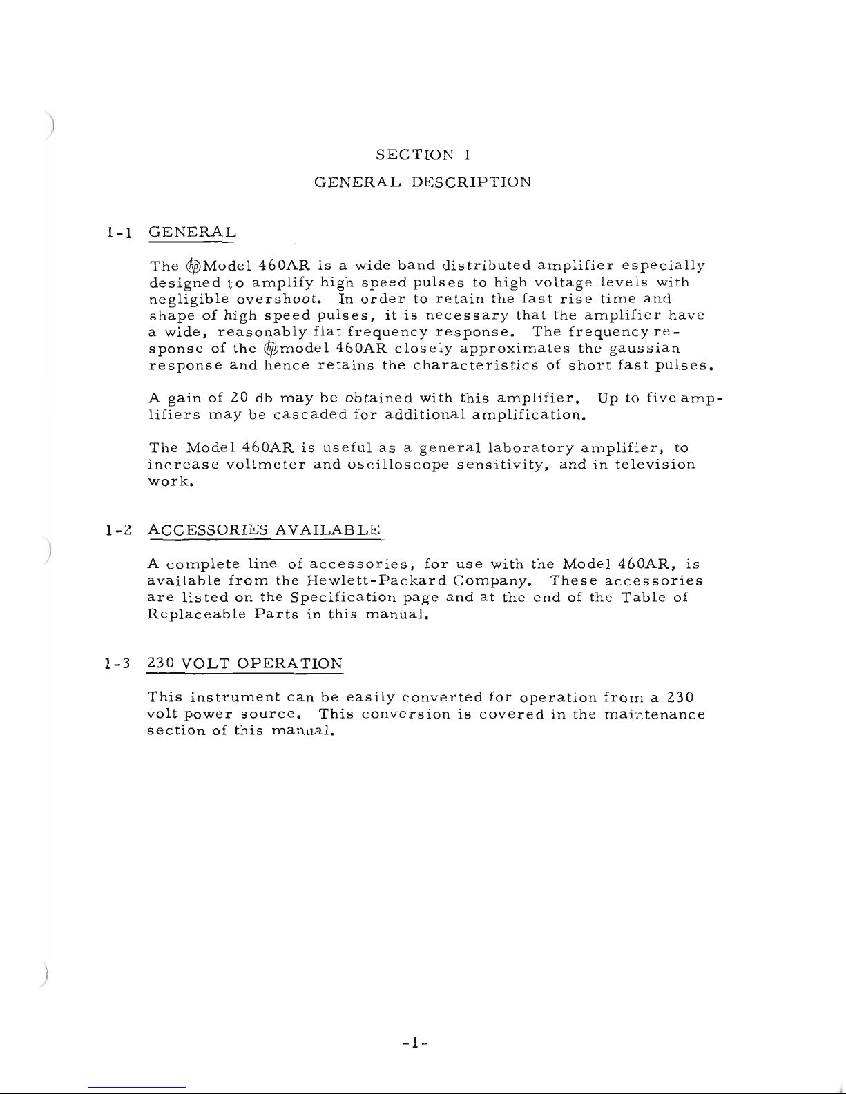
2-4
OPERATION
The
input
circuit
of
the
Model
460AR
isaterminated
transmission
line
withacharacteristic
impedance
of
200
ohms.
The
output
circuit
has
an
impedance
of
280
ohms
(resistive).
The
load
impedance
determines
the
gain
of
the
amplifier.
Therefore.
it
is
not
neces
sary
to
match
the
load
to
the
output
of
the
amplifier
unless
the
gain
is
adversely
affected.
Shown
below
are
two
dia-
grams
for
connecting
a
matched
or
unmatched
load
to
the
Model
460AR
using
a
200
ohm
cable.
Connect
acros
s
output
Jack
inside
instrument
200
ohms
load
,-,
4'-----+/-'
.-0--'
-----,
Model
460AR
OUTPUT
~~~----'
-L"""
200
ohm
cable
<
,
, \
•
j
,
,
620
To
any
ohms
load
Model
460AR
OUTPUT
200
ohm
cable
The
GAIN
control
will
vary
the
gain
of
the
amplifier
over
a
range
of
approximately
6
db.
This
control
is
provided
so
that
the
gain
of
the
amplifier
can
be
set
toaknown
value
if
nec-es
sary.
There
is
no
feedback
in
the
amplifier.
so
the
gain
is
directly
proportional
to
the
Gm
of
the
tubes.
The
gain
is
also
determined
by
the
output
load
and
will
vary
with
output
load
in
accordance
with
the
relation
280
X
ZL
280+ZL
The
Wide
Band
Amplifier
can
be
used
with
the
<$Model
410
Vacu-
um
Tube
Voltmeter
to
provide
additional
sensitivity
in
measuring
high
frequencies.
A
special
adaptor
is
available
to
connect
the
probe
of
the
Model
410
to
the
output
terminal
of
the
amplifier.
The
overall
frequency
response
of
the
Model
460AR.
in
combina-
tion
with
the
Model
410.
is
within
1
db
out
to
190
me.
This
combi-
nation
will
give
a
full
scale
meter
reading
on
the
Model
410
with
1/10
volt
applied
to
the
input
of
the
Model
460AR.
-4-
Page 9

Several
amplifiers
can
be
cascaded
when
more
than
20
db
gain
is
desired.
The
maximum
gain
which
can
be
used
will
be
limited
by
the
effective
noise
generated
in
the
input
circuit
of
the
amplifier.
The
noise
figure
is
approximately
10
db.
When
amplifiers
are
cascaded.
the
rise
time
will
be
greater
than
that
ofasingle
unit
in
accordance
with
the
relation:
1/2
T • t
(n)
where:
T
is
total
rise
time
t
is
the
rise
time
ofasingle
unit
(3
X
10-9
sec.)
n
is
the
number
of
460
units.
The
total
rise
time
of
any
number
of
460
Amplifiers
in
conjunction
with
any
load
may
be
found
approximately
by
the
following
relation:
T
'"
[nt
2
+
(440C)2J
1/2
where:
)
2-5
CIRCUIT
DESCRIPTION
n •
number
of
460
Amplifiers
t -
rise
time
of
one
460
=
2.6
X
10-9
sec.
C •
total
shunt
capacitance
on
the
output
of
the
460
in
farads.
T =
total
rise
time.
The
Model
460AR
is
an
amplifier
which
hasavery
wide
transmiss-
ion
band.
It
has
two
stages
with
five
tubes
in
the
first
stage
and
seven
tubes
in
the
second
stage.
The
grids
of
these
tubes
are
con-
nected
along
one
transmission
line
for
the
input
circuit
and
the
plates
of
the
tubes
are
connected
along
a
second
transmission
line
for
the
output
circ
uit.
A
wave
traveling
down
the
input
line
ex-
cites
the
grids
in
succession
and
half
of
the
corresponding
wave
generated
in
the
plate
circuit
travels
down
the
plate
line
toward
the
output
and
is
reinforced
at
each
successive
plate.
The
part
of
the
wave
in
the
plate
line
which
travels
in
the
reverse
direction
is
absorbed
byatermination
of
the
other
end
of
that
line.
By
the
time
the
wave
in
the
plate
line
reaches
the
output.
it
has
been
am-
plified
by
about
10
db.
The
second
stage
adds
another
10
db
to
make
a
total
of
20
db
gain
for
the
unit.
The
Model
460AR
will
amplify
pulses
with
an
extremely
short
rise
time
and
with
virtually
no
overshoot.
The
time
of
rise
of
the
am-
plifier
itself
is
approximately
3
millimicroseconds.
The
amplifier
has
an
amplitude
response
closely
matching
the
Gaussian
Curve.
which
is
the
ideal
transmission
for
pulse
amplifications
when
ring-
or
overshoot
cannot
be
tolerated.
-5-
Page 10

)
SECTION
III
MAINTENANCE
3
-1
COVER
REMOVAL
You
will
be
able
to
slide
the
one-piece
cover
off
of
the
instrument
after
removing
the
four
screws
in
the
rear
of
the
cover.
3-2
TUBE
REPLACEMENTS
In
many
cases
instrument
malfunction
can
be
corrected
by
replac-
ingaweak
or
defective
tube.
Before
making
any
internal
adjust-
ment
or
component
replacement,
check
the
tubes.
Adjustments
made
in
an
attempt
to
compensate
for
a
defective
tube
will
often
complicate
the
repair
problem.
It
is
good
practice
to
check
tubes
by
substitution
rather
than
by
the
use
ofa"tube
checker".
The
res
ults
obtained
from
the
"tube
checker"
can
be
misleading.
Mark
original
tubes
to
insure
return
to
the
same
socket.
Replace
only
tubes
proved
to
be
weak
or
de-
fective.
Any
tube
with
corresponding
standard
EIA
(JEDEC)
characteristics
can
be
used
as
a
replacement.
3-3
POWER
SUPPLY
Rectifier
CRI
is
connected
inahalf-wave
circuit.
The
dc
output
voltage
between
ground
and
the
junction
of
C96
and
L25
should
be
110 ±:lO
volts
with
the
line
voltage
set
to
115
volts.
The
GAIN
control
should
be
set
fully
clockwise
to
maximum.
Ripple
voltage
can
be
quite
high
without
affecting
instrument
performance.
Low
power
supply
voltages
are
generally
due
toaweak
selenium
rectifier,
leaky
filter
capacitors,
shorted
tubes
or
off
value
plate
line,
grid
line,
or
screen
resistors.
3-4
230
VOLT
OPERATION
The
r$fJ
Model
460AR
can
be
quickly
and
easily
converted
to
operate
from
a
nominal
230
volt
50/1000
cps
power
source.
The
instrument
is
normally
supplied
with
the
dual
primary
windings
of
the
power
transformer
connected
in
parallel
for
115
volt
operation.
To
con-
vert
for
230
volt
operation,
reconnect
the
primary
windings
in
series
as
shown
on
the
schematic
diagram.
The
line
fuse
F I
must
also
be
changed
from
O.6amp.
slow-blow
to
0.4
amp.
slow-blow.
-7-
Page 11

3-5
TROUBLE
SHOOTING
Low
gain,
low
output,
and
impaired
frequency
response
are
all
di-
rectly
related
to
tube
mutual
conductance
and
power
supply
output
voltage.
Consequently,
should
any
of
the
above
symptoms
appear,
the
power
supply
output
voltages
should
be
checked
(Paragraph
3-3)
and
the
tubes
should
be
checked
(Paragraph
3
-2).
Impaired
frequency
response,
low
gain,
and/or
excessive
hum
can
also
be
caused
by
open
or
shorted
coils
and
by
defective
terminat-
ing
resistors
or
screen
resistors.
The
can
of
electrolytic
capacitor
C9
is
insulated
from
the
chassis.
If
this
capacitor
is
shorted
to
the
chassis
the
bias
voltage
will
also
be
shorted.
The
bias
voltage
is
normally
not
more
than
about
1.
8
volts
and
is
not
dangerous
to
personnel
but
tube
damage
can
result
if
this
voltage
is
removed.
3-6
REPLACEMENT
OF
200
OHM
CABLE
CONNECTOR
1.
Connect
200
ohm
cable
to
length
desired.
Trim
end
of
cable
toapoint
where
shielding
and
outer
ins
ulation
are
even
with
the
end
ofacenter
conductor
support
bead.
After
assembly,
cable
length
to
tip
of
banana
plug
will
be
approximately
1/4"
shorter
than
trimmed
cable
length.
FRONT
PLUG
ASSEMBLY
(46A-16CI
CONICAL
WASHER
146A-16Kl
REAR
PLUG
BODY
/
BANANA
PLUGj
(46A-16J) (/25-33)
[D
DD
ICROSS
SECTIONSI
'----.,----J
CENTER
CONDUCTOR
SHIELDING
I
OUTERINSULATION
CAP
·0·
RING
1432-40)
LARGE
WASH~R
IIOR2.
SEE
TEXTI
(512-134)
\.
,2·
(SEE
TEXTll
I
REAR
RETAINER
(46A
-16H
I
200
OHM
CABL
E
(812-52)
LO-..-52
Figure
3-1.
Exploded
View
of
the
46A-95B
Assembly
2.
Remove
outer
cable
insulation
foradistance
of
2"
from
cable
end.
3.
Remove
three
support
beads
from
center
conductor.
To
do
this,
upset
shielding
just
enough
to
release
beads.
-8-
Page 12

)
)
)
4.
Slide
the
following
parts
over
the
cable
shielding
in
order
given:
rear
retainer
cap,
large
washer{s),
rubber
"0"
ring.
Either
one
or
two
washers
are
included
with
the
connector
parts
at
the
factory.
Use
all
of
the
large
512-134
washers
supplied.
Pur-
pose
of
additional
washer
is
given
in
step
9.
5.
Slide
rear
plug
body
over
shielding.
Hold
rear
plug
body
against
end
of
outer
insulation
and
cut
off
shielding
3/16"
from
beveled
end
of
rear
plug
body.
6.
Fan
shielding
out
and
bend
back
over
rear
plug
body.
Trim
off
any
shield
wire
protruding
beyond
beveled
edge.
7.
Place
conical
washer
over
shielding
with
flat
side
toward
end
of
plug.
8.
Insert
center
conductor
through
hole
in
center
of
front
plug
assembly,
slide
assembly
back
over
conical
washer.
Thread
rear
retainer
cap
on
front
plug
assembly.
Plug
must
be
firm-
ly
tightened
so
that
it
cannot
be
rotated
on
end
of
cable.
The
use
of
strap
wrenches
is
recommended.
9.
Measure
distance
between
front
edge
of
rear
retainer
cap
and
front
edge
of
front
plug
assembly.
This
distance
must
not
be
less
than
31/32".
Additional
washers
installed
as
in
step
4
will
increase
this
distance.
10.
Wrap
and
solder
the
center
conductor
to
the
base
of
the
banana
plug.
Do
not
pull
center
conductor
excessively
tight
when
con-
necting
to
banana
plug.
11.
Resistance
between
outer
connectors
must
be
lessthan
one
ohm.
Resistance
between
center
connectors
must
be
less
than
one
ohm.
Resistance
between
outer
connectors
and
center
connectors
must
be
greater
than
500
megohms.
3-7
TEST
PROCEDURE
Testing
of
the
460AR
isalong
tedious
procedure
and
is
not
often
needed.
However,
anyone
with
the
necessary
equipment
for
mak-
ing
the
several
somewhat
complex
test
set-ups
can
complete
the
procedure.
The
following
r!$
instruments
or
their
equivalent
will
be
required.
-
Signal
Sources
-
Models
2l2A,
608C,
and
650A.
-
Voltmeters
- - - -
Models
410B
and
400D/H/L.
-
Oscilloscope
- - - - - - - - - -
Model
l50A.
-
Attenuators
- - - - -
Models
355A
and
355B.
-
Miscellaneous
- - - - - - -
Cable
Adapters.
-9-
Page 13

The
complete
Test
Procedure
is
available
from
the
~
Factory
as
a
Service
Note.
Perhaps
your
most
convenient
source
for
these
Service
Notes
is
your
local
~
Representative
who
will
be
pleased
to
supply
you
with
copies
on
request.
Your
c§f>
Representative
also
maintains
complete
facilities
and
spe-
cially
trained
personnel
to
assist
you
with
any
engineering,
appli-
cation,
test,
or
repair
problems
you
may
have
with
~
instruments.
-10-
Page 14

~
Q)
....
>
0.
0
E-4
~
0
...0
.;t<
~
Q)
'"C
)
0
~
.
N
I
('f)
Q)
'"'
:j
0.0
....
~
)
-11-
Page 15

-12-
Page 16

'-
'--../
----./
1000
MC
100
MC
10
MC
fREQIJENCY
IMC
~
~
V
~
-
..
,
;::
......
V
A
./
....
..
'
..
~~
V1
~
'\
~\\
\
"
',\
\,
~\
',\
A =
Amplifier
with
410
Voltmeter
Adapter
\~
,
B =
Amplifier
working
into
200-,,-
Resistance
Load
1\
C =
Gaussian
Curve
-
Optimum
for
Pulse
,
~
\
8
2
4
6
o.
100
KC
14
16
18
20
22
~
12
"-
~
10
:..
~
w
~
,
Figure
3-4.
Typical
Response
Curves
Model
460A
Wide
Band
Amplifier
Page 17

LII
LI2
L13
LI4
LI5
L16
CI9
+100
{--<
.05lJ~
J2
10UTPUTI
V6
CII
5654
'~rl
1
1
LJF
CI8
;
.01
lJF
L6
-:x:-
RII
N'
•
12
RIO
270
R2
•
12
RI
270
SEE TRANSFORMER
[)[TAIL
.6A
0
(FUSE!
[Qiil
o
'o-8LK.
~"".
I
FI
SI " ,
II~V
~O/lOOO
'V
1 WHITE
K.
1000
OHM'
III-
I WEGDH
..
YELLOW
YEl.LOW
---...--;;
I
.....
OR
..
NG(c
CR-Il
120~
1
it
,.eTO"Y
ADJUSTMENT
o
',Ull.
CDNT"Ol.
CAPACITY
IN
J,lUF
UNLlSS
OTNUIWISE:
NOTED
CONDITIONS
Of
DC
YOLTAGE
MUSUREMENT
I.
11&
VOl.T.
'011000""'
POWER
SUPPLY
t.
MEASURED
IIETWUN
THE
INDICATED
POINTS
AND
CHASSIS
WITH
A
VOLT-
METER
OF
100
MEGOHM'
INPUT
R£SIST-
ANCIE
,.
"22
AT
M"X'MUM
OAIN
R
18
12
....
"ED-YELLOW
TI
~
C90
40
lJF
-/.6
50
T
*R23
18
RI7
12
I GAIN I
C9b
30
lJF
RI6
12
R7
12
L5
1
RI5
12
R6
12
L4
RI4
12
R5
12
V4
5654
1
L3
1
RI3
12
R4
12
L2
1
RS
L7
I I
L8
I I
195
C8
5600
1.
C9c
±---+--tl.
01
T
20
lJF
LJF
RI2
12
R3
12
LI
+/00
C2
II
.01
lJF
L
....
CIO
.01
lJF
CI
.01
lJF
>-
JI
IINPUT
I
I
.-
~
I
L--fm'--+---I--fm'--+---I--J'-m"--+---I--fm'--+---I-J"l~'---+---+--fm"--+---+-J"l~'---+---I---I-'\II/\r::;'-'\N'v--.
C20
.01
lJF
c:c:>f'YltIOHT
ltU
&Y
HlWlm.'ACKAlO
COMPANY
ThI
...
,_
I'IRI.rMl
...
'...
rh.,.'.lIu
I,",
_1
_
••
f H
••
I.".'.d.
....
~vl,·
....
1
••
U'
k
Jlet,.
h"'"
eH\MW4,
•
.,
,.,.,
...
""
..
wl~.rItt
c
......
I.lth.
H
••
l.".'.c.
....
t1
c.
,.
MO.·
...
-'
••••
TRANSFO'U4EA
DETAIL
TI
lI'V
}>OV
II'V
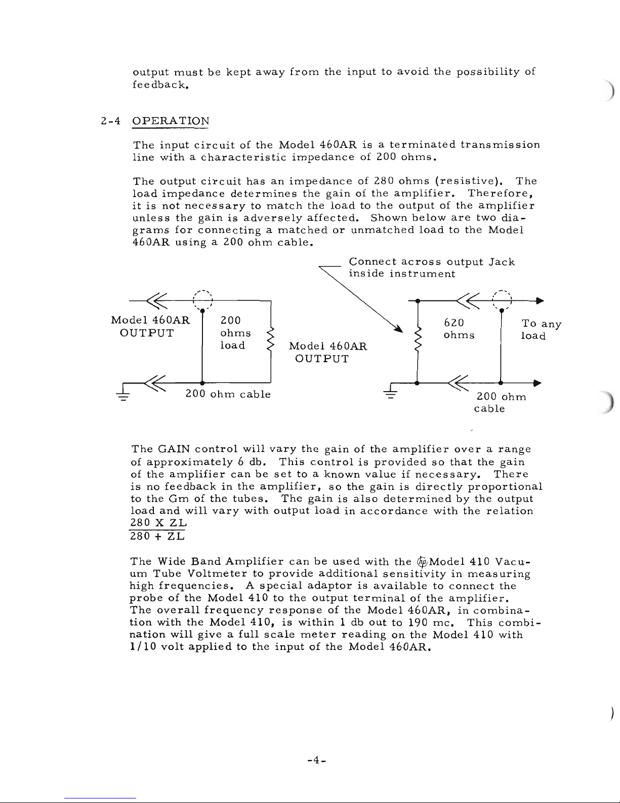
Figure
3-5.
Model
460AR
Wide
Band
Amplifier
Page 18

)
Sect.VPage
1
SECTION
V
TABLE
OF
REPLACEABLE
PARTS
r------------------
NOTE---------------------,
Standard
components
have
been
used
in
this
instrument,
whenever
possible.
Special
components
may
be
obtained
)
)
from
your
local
Hewlett-Packard
representative
or
from
the
factory.
When
ordering
parts
always
include:
1.

00019-2
TABLE
OF
REPLACEABLE
PARTS
Circuit
Description
Mfr.
•
~
TQ
RS
Ref.
Stock
No.
C1
Capacitor:
fixed,
ceramic,
56289
0150-0012 1 1
. 01
Ilf
± 20%, 1000 vdcw
C2
Capacitor:
fixed,
ceramic,
91418
0150-0098 3 1
.01
Ilf
± 20%, 100 vdcw
C3
thru
Capacitor:
fixed,
ceram
ic,
56289
0150-0012
13 3
C7
.01
Ilf
± 20%, 1000 vdcw
C8
SameasC2
C9A,B,C
Capacitor:
fixed,
electrolytic,
56289 0180-0053
1 1
3
sections,
40 x 30 x
20
Ilf,
150 vdcw
C10
SameasC3
C11
Capacitor:
fixed,
ceramic,
91418
0150-0097
1 1
.0068
Ilf
± 20%, 1000 vdcw
C12
thru
SameasC3
C18
C19
Capacitor:
fixed,
ceramic,
19701
0150-0052
1 1
.05
Ilf
± 10%, 400 vdcw
C20
SameasC2
CR1
Rectifier,
metallic
21964
1880-0001 1 1
F1
Fuse,
cartridge:
.6
amp,
slow-blow
75915
2110-0016 1 10
(for
115
volt
operation)
Fuse,
cartridge:
.4
amp,
slow-blow
75915
2110-0019 1 0
(for
230
volt
operation)
11
Lamp,
incandescent:
6-8V,
24455
2140-0012
1
1
2 pin
base,
#12
J1,2
Jack,
panel
28480 46A-76 2 0
Knob: GAIN
28480
G-74K
1 0
L1
thru
Coil
Assembly
28480 46A-95L
1 1
L5
L6
thru
Coil
Assembly
28480
46A-95N 1 1
L10
L11
thru
Coil
Assembly
28480 46A-95M 1 1
L17
L18
thru
Coil
Assembly
28480
46A-95P
1
1
L24
•
Referto"ListofManufacturers'
Codes".
TQ
Total
Quantity
usedinthe
instrument.
RS
Recommended
spares
for
one
year
isolated
service
for
one
instrument.
- 16 -
Page 20

)
)
00019-2
TABLE
OF
REPLACEABLE
PARTS
Circuit
Description
Mfr.
*
<Fj;
TQ
RS
Ref.
Stock
No.
L25
Reactor:
6h
28480
9110-0017 1 1
PI
Cord,
power
70903
8120-0050 1 1
R1
Resistor:
fixed,
deposited
carbon,
19701
0730-0008
11
3
277
ohms±1%,
1 W
Optimum
value
selectedatfactory
Average
value
shown
R2
thru
Resistor:
fixed,
composition,
01121
0687-1201 14
3
R7
12
ohms
±10%,
1/2
W
R8
Resistor:
fixed,
deposited
carbon,
19701
0721-0008
2 1
195
ohms
±1%,1/8W
R9
Resistor:
fixed,
composition,
01121 0687-5621 2 1
5,600
ohms
±10%,
1/2
W
RIO
SameasR1
R11
thru
SameasR2
R18
R19
SameasR8
R20
SameasR9
R21
Not
assigned
R22
Resistor:
variable,
wirewound,
71590 2100-0002 1 1
50
ohms
±10%, 3 W
R23
Resistor:
fixed,
composition
01121 0690-1801 1 1
18
ohms
±1O%, 1 W
Optimum
value
selectedatfactory
Average
value
shown
Sl
Switch, toggle:
SPST
04009 3101-0001 1 1
T1
Transformer,
power
28480 9100-0065 1 1
VI
thru
Tube,
electron:
5654 86684
1923-0001 12 12
V12
MISCELLANEOUS
Jewel,
pilot
lamp
72765 1450-0020 1 1
Lampholder:
for
2 pin
base
72765
1450-0022
1
0
*
Referto"ListofManufacturers'
Codes".
TQ
Total
Quantity
usedinthe
instrument.
RS
Recommended
spares
for
one
year
isolated
service
for
one
instrument.
- 17 -
Page 21

LIST
OF MANUFACTURERS
The following
code
numbers
are
from
the
Federal Supply
Code
for Manufacturers
Cataloging
Handbooks H4-1 (NametoCode)
and H4-2
(CodetoName) and their latest supplements. The
dateofrevision and
the
dateofthe
supplements used
appear
at
the
bottomofeach
page.
Alphabetical
codes
have been arbitrarily assignedtosuppliers not
appearinginthe
H4
handbooks.
CODE
NO.
MANUFACTURER
ADDRESS
CODE
NO.
MANUFACTURER
ADDRESS
CODE
NO.
MANUFACTURER
ADDRESS
1
8873
E.J.DuPont
and
Co.,
Inc.
Wilmington,
Del.
Quincy, Mass.
Fullerton,
Calif.
Brooklyn, N.Y.
Keasbey,
N.J.
Oakland,
Calif.
Chicago,
III.
Philadelphia,
Pa.
Chicago,
III.
Erie, Pa.
Princeton, Ind.
Pasadena,
Calif.
Princeton, Ind.
Camden,
N.J.
Mt. Vernon, N.Y.
Srooklyn, N.Y.
Harrisburg,
Pa.
New York, N.Y.
San Francisco,
Calif.
St. Marys, Pa.
Hartford,
Conn.
Chicago,
III.
New Rochelle, N.Y.
New York, N.Y.
Chicago,
III.
Columbus,
Ohio
Defiance,
Ohio
New York, N.Y.
Boston, Mass.
Lenz Electric Mfg.
Co.
Liltlefuse Inc.
Lord Mfg.
Co.
C.W.Marwedel
Micamold
Electronic
Dialight
Corp.
General
Ceramics
Corp.
Girard·Hopkins
Drake Mfg.
Co.
HughH.Eby Inc.
Gudeman
Co.
Erie Resistor
Corp.
Hansen
Mfg.
Co.,
Inc.
Helipot
Div. of Beckman
Instruments, Inc.
73293
Hughes
Products
Div.ofHughes
Aircraft
Co.
Newport
Beach,
Calif.
73445
Amperex
Electronic
Co.,
Div.
of
North
American
Phillips
Co.,
Inc.
Hicksville, N.Y.
73506
Bradley
Semiconductor
Corp.
New
Haven,
Conn.
73559
Carling
Electric, Inc.
Hartford,
Conn.
73682
GeorgeK.Garrett
Co.,
Inc.
Philadelphia,
Pa.
Fischer
Special
Mfg.
Co.
Cincinnati,
Ohio
The
General
Industries
Co.
Elyria,
Ohio
Jennings
Radio Mfg.
Co.
San
Jose,
Calif.
J.
H. Winns,
and
Sons Winchester, Mass.
Industrial
Condenser
Corp.
Chicago,
III.
Industrial Products
Co.
Danbury,
Conn.
E.F.Johnson
Co.
Waseca,
Minn.
International
Resistance
Co.
Philadelphia,
Pa.
Sandwich, III.
72619
72656
72758
72765
72825
72928
72982
73061
73138
7 5 378James
Knights
Co.
75382
Kulka Electric Mfg.
Co.,
Inc.
Mt. Vernon, N.Y.
Chicago,
III.
Des Plaines,
III.
Erie, Pa.
San Francisco,
Calif.
Mfg.
Corp.
Brooklyn, N.Y.
Inc.
Malden,
Mass.
San
Leandro,
Calif.
Cleveland,
Ohio
Chicago,
III.
73743
73793
73905
74455
74861
74868
74970
75042
7581
8
7591
5
76005
76
210
76433
76487
76
5 3 0
76
5 4 5
768
5 4
77068
James
Millen Mfg.
Co.,
Monadnock
Mills
Mueller Electric
Co.
Oak
Manufacturing
Co.
Bendix
Corp.,
Bendix
Pacific Div. No. Hollywood,
Calif.
77221
Phaostron
Instrument
and
Electronic
Co.
South
Potter
and
Brumfield, Inc.
Radio
Condenser
Co.
Radio Essentials Inc.
Radio
Receptor
Co.,
Inc.
Resistance Products
Co.
Signal
Indicator
Corp.
Tilley Mfg.
Co.
Stackpole
Carbon
Co.
Veeder
Root, Inc.
Wenco
Mfg.
Co.
Zierick Mfg.
Corp.
Times
Facsimile
Corp.
Oxford
Electric
Corp.
Aero
Manufacturing
Co.
All
Star
Products
Inc.
Hammerlund
Co.,
Inc.
Stevens,
Arnold,
Co.,
Inc.
I
nternational
Instruments, Inc.
New
Haven,
Conn.
81415
Wilkor
Products, Inc.
Cleveland,
Ohio
81
453
Raytheon Mfg.
Co.,
Industrial
Tube Division
773
4 2
776
3 0
776
3 4
77
6 3 8
777
64
78283
7847
1
78488
79142
7925
1
799
6 3
801
30
80248
80411
80486
80583
80640
8 1
030
Akron,
Ohio
Inc.
Keene,
N.H.
Chicago,
III.
Skokie,
III.
Miniature Precision Bearings,
Muter
Co.
Ohmite
Mfg.
Co.
Precision Thermometer
and
Inst.
Co.
Philadelphia,
Pa.
Shallcross Mfg.
Co.
Selma,
N.C.
Sonotone
Corp.
Elmsford, N.Y.
Sorenson &
Co.,
Inc. So. Norwalk,
Conn.
Spaulding
Fibre
Co.,
Inc.
Tonawanda,
N.Y.
Sprague
Electric
Co.
North
Adams,
Mass.
Union Switch
and
Signal,
Div.ofWestinghouse
Air
40920
54294
55933
55938
56137
56289
61775
42190
44655
48620
Brake
Co.
Pittsburgh,
Pa.
62
1 1 9 Universal Electric
Co.
Owosso, Mich.
64959
Western
Electric
Co.,
Inc. New York, N.Y.
65092
Weston
Inst. Div.ofDaystrom, Inc.
Newark,
N.J.
70
1 1 9
Advance
Electric
and
Relay
Co.
Burbank,
Calif.
Hartford,
Conn.
New York, N.Y.
New York, N.Y.
Chicago,
III.
Cleveland,
Ohio
New York, N.Y.
Cleveland,
Ohio
Paramus,
N.J.
1
9500
Thomas A. Edison Industries,
Div. of
McGraw·Edison
Co.
West
Orange,
N.J.
1
9701
Electra
Manufacturing
Co.
Kansas City, Mo.
20183Electronic Tube
Corp.
Philadelphia,
Pa.
2 1
520
Fansteel
Metallurgical
Corp.
No.
Chicago,
III.
21
335
The Fafnir Bearing
Co.
New Britain, Conn.
21
964
Fed.
Telephone
and
Radio
Corp.
Clifton,
N.J.
24446
General
Electric
Co.
Schenectady,
N.Y.
24455
G.
E.,
Lamp Division
Nela
Park,
Cleveland,
Ohio
24655
General
Radio
Co.
West
Concord,
Mass.
26462
Grobet
File
Co.ofAmerica,
Inc.
Carlstadt,
N.J.
26992
Hamilton
Watch
Co.
Lancaster,
Pa.
28480
Hewlett·Packard
Co.
Palo Alto,
Calif.
33173G.E.
Receiving Tube
Dept.
Owensboro,
Ky.
35434
Lectrohm Inc.
Chicago,
III.
37942
P.R.Mallory &
Co.,
Inc.
Indianapolis,
Ind.
39543
Mechanical
Industries Prod.
Co.
70276
70309
70563
70903
70998
71002
71
2 1 8
71286
71
3 1 3
Allen Mfg.
Co.
Allied
Control
Co.,
Inc.
Amperite
Co.,
Inc
Belden Mfg.
Co.
Sird Electronic
Corp.
Birnbach Radio
Co.
Bud
Radio
Inc.
Camloc
Fastener
Corp.
AllenD.Cardwell
Electronic
Prod.
Corp
Plainville,
Conn.
71
400
Bussmann Fuse Div.ofMcGraw·
Edison
Co.
St. Louis, Mo.
Chicago
Telephone
Supply
Co.
Elkhart, Ind.
Cannon
Electric
Co.
Los
Angeles,
Calif.
Cinema
Engineering
Co.
Burbank,
Calif.
C.P.Clare&Co.
Chicago,
III.
Centralab
Div.ofGlobe
Union Inc.
Milwaukee, Wis.
71700
The Cornish
Wire
Co.
New York, N.Y.
71
744
Chicago
Miniature
Lamp
Works
Chicago,
III.
71753
A.O.Smith
Corp.,
Crowley Div.
West
Orange,
N.J.
71
785
Cinch
Mfg.
Corp.
Chicago,
III.
7 1
984
Dow
Corning
Corp.
Midland,
Mich.
72136
Electro Motive Mfg.
Co.,
Inc.
Willimantic,
Conn.
71450
71468
71471
71482
71590
Teterboro,
N.J.
Colton,
Calif.
New York, N.Y.
New Bedford, Mass.
Boonton,
N.J.
Cap.
Div.
Marion,
III.
Los
Angeles,
Calif.
Milwaukee, Wis,
Beverly Hills,
Calif.
Inc.
Culver
City,
Calif.
CarlE.Holmes
Corp.
Allen Bradley
Co.
Litton Industries, Inc.
Pacific
Semiconductors,
Humidial
Co.
Westrex
Corp.
Aeroyox
Corp.
Aircraft
Radio
Corp.
Sangamo
Electric
Co.,
Corning
Glass Works
Electronic
Components
Dept.
8radford,
Pa.
Avnet
Corp.
Los
Angeles,
Calif.
Fairchild
Semiconductor
Corp.
Mountain View,
Calif.
Rheem
Semiconductor
Corp.
Mountain View,
Calif.
800nton,
N.J.
Boonton
Radio
Corp.
Cannon
Electric
Co.
Phoenix Div. Phoenix, Ariz.
Camloc
Fastener
Corp.
Los
Angeles,
Calif.
CBS Electronics
Semiconductor
Operations,
Div. of C.B.S. Inc.
Lowell, Mass.
Houston, Texas
Chicago,
III.
Niagara
Falls, N.Y.
Dover,
N.H.
00891
01121
01255
01
281
00334
00335
00656
00781
00853
071
15
01
295
Texas Instruments, Inc.
Semiconductor
Components
Div.
Dallas, Texas
01
349
The
Alliance
Mfg.
Co.
Alliance,
Ohio
021
1 4
Ferroxcube
Corp.ofAmerica
Saugerties,
N.Y.
02286
Cole
Mfg.
Co.
Palo Alto,
Calif.
02660
Amphenol
Electronics
Corp.
Chicago,
III.
o2 7 3 5 Radio
Corp.ofAmerica
Semiconductor
and
Materials
Div.
Somerville,
N.J.
02777
Hopkins
Engineering
Co.
San Francisco,
Calif.
03508
G.E.
Semiconductor
Products
Dept.
Syracuse, N.Y.
03705
Apex
Machine
& Tool
Co.
Dayton,
Ohio
03797
Eldema
Corp.
EI
Monte,
Calif.
04009
Arrow,
Hart
and
Hegeman
Elect.
Co.
Hartford,
Conn.
04
2 2 2
Hi.Q
DivisionofAerovox Myrtle Seach,
S.C.
04404
Dymec Inc. Palo Alto,
Calif.
04651
Special
Tube
Operations
of
Sylvania Electronic Systems
Mountain View,
Calif.
0471
3
Motorola,
Inc.,
Semiconductor
Prod. Diy. Phoenix, Arizona
04777
Automatic
Electric Sales
Corp.
Northlake,
III.
05
6 2 4
Sarber
Colman
Co.
Rockford,
III.
05783
Stewart
Engineering
Co.
Soquel,
Calif.
o6 0 0 4 The Bassick
Co.
Bridgeport,
Conn.
0681
2 Torrington Mfg.
Co.,
West.
Div.
Van Nuys,
Calif.
07933
07261
07263
1931
5 Eclipse Pioneer, Div. of
Sendix
Aviation
Corp.
08733
08792
07980
0871
S
Texas
Capacitor
Co.
Electro Assemblies, Inc.
Carborundum
Co.
Clarostat
Mfg.
Co.
Cornell
Dubilier
Elec.
Corp.
So. Plainfield,
N.J.
15909
The Daven
Co.
Livingston,
N.J.
1
6758
Delco Radio Div. ofG.M.
Corp.
Kokomo, Ind.
091
34
09250
10646
126
9 7
1
4655
00015-1
Revised:10Jan.
1961
From:
F.S.C.
Handbook
Supplements
H4-1
Dated
July
1960
H4-2
Dated
July
1960
Page 22

LIST
OF MANUFACTURERS
CONTINUED
)
CODE
NO. MANUFACTURER
ADDRESS
CODE
NO.
MANUFACTURER
ADDRESS
CODE
NO. MANUFACTURER
ADDRESS
Calif.
Lansdale,
Pa.
Palo
Alto,
Calif.
Waltham,
Mass.
Palo Alto,
Calif.
East
Aurora,
N.Y.
Indianapolis,
Ind.
Boston, Mass.
Palo
Alto
Engineering
Co.,
Inc.
Clevite
Transistor
Prod.
Div.ofClevite
Corp.
Varian
Associates
Delevan Electronics
Corp.
Wileo Corporation
Renbrandt,
Inc.
Technology
Instruments
Corp.
of
Calif.
No.
Hollywood,
98
9 2 5
98
7 3 4
993
1 3
99
a0 0
998
4 8
99934
99
9 5 7
00000
0000
E
0000
F
0000
G
0000
H
THE
FOLLOWING
H·P VENDORS HAVE
NO
NUM·
BER
ASSIGNEDINTHE
LATEST
SUPPLEMENT TO
THE FEDERAL
~UPPLY
CODE
FOR MANUFACTURERS
HANDBOOK.
0000AAmp,
Inc.
Hawthorne,
Calif.
0000BChicago
TelephoneofCalif.
S.
Pasadena,
Calif.
0000CConnor
Spring
Mfg.
Co.
San
Francisco,
Calif.
Connex
Corp.
Oakland,
Calif.
Fisher Switches, Inc. San
Francisco,
Calif.
Malc~
Tool
and
Die
Los
Angeles,
Calif.
Microwave
Engineering
Co.
Palo Alto,
Calif.
Philco
Corp.
(Lansdale
Tube
Division)
0000
I Telefunken
(c/o
American
Elite)
OOOOJTiTal, Inc.
0000
K Transitron Electronic
Sales
New York, N.Y.
Berkeley,
Calif.
Corp.
Wakefield,
Mass.
0000LWinchester
Electronics, Inc.
Santa
Monica,
Calif.
0000MWestern
Coil
Div.ofAutomatic
Ind.,
Inc.
Redwood
City,
Calif.
0000
N Nahm-Bros.
Spring
Co.
San
Leandro,
Calif.
0000
P Ty-Car
Mfg.
Co.,
Inc.
Holliston,
Mass.
Yonkers, N.Y.
Danvers, Mass.
Jam!lica,
N.Y.
Pasadena,
Calif.
New Rochelle, N.Y.
Redwood
City,CaIif.
Augat
Brothers, Inc.
Attleboro,
Mass.
Dale
Products, Inc.
Columbus,
Neb.
Elco
Corp.
Philadelphia,
Pa.
Gremar
Mfg.
Co.,
Inc.
Wakefield,
Mass.
Micro-Switch Div.ofMinneapolis
Honeywell
Regulator
Co.
Freeport,
111.
Sylvania
Electric
Prod.
Inc.,
Semiconductor Div. Woburn,
Mass.
Stevens Mfg.
Co.,
Inc.
Mansfield,
Ohio
Insuline-Van
Norman
Ind.,
Inc.
Electronic Division Manchester,
N.H.
Raytheon Mfg.
Co.,
Receiving
Tube Div. Quincy, Mass.
Raytheon Mfg.
Co.,
Semi-
conductor Div.
Tung-Sol Electric, Inc.
Curtiss-Wright
Corp.,
Newton,
Mass.
Newark,
N.J.
Electronics Div.
Carlstadt,
N.J.
Tru
Ohm
Prod.
Div.ofModel
Engineering
and
Mfg.
Co.
Chicago,
111.
Allies
Products
Corp.
Miami, Fla.
Continental
Connector
Corp.
Woodside,
N.Y.
Lucraft
Mfg.
Co.,
Inc. New York, N.Y.
National
Coil
Co.
Sheridan,
Wyo.
Weckesser
Co.
Chicago,
III.
Huggins
Laboratories
Sunnyvale,
Calif.
Hi-Q
DivisionofAerovox
Olean,
N.Y.
Solar
Manufacturing
Co.
Los
Angeles,
Calif.
Microwave
Associates,
Inc. Burlington, Mass.
Excel
Transformer
Co.
Oakland,
Calif.
Automatic
and
Precision
Mfg.
Co.
CBS Electronics,
Div.
of
C.B.S., Inc.
Axel Brothers Inc.
Francis
L.
Mosley
Sealectro
Corp.
Carad
Corp.
95236
95
238
94154
94197
94145
94310
9333
2
93410
939
8 3
94144
91506
91637
91662
9 1
737
91929
95263
95265
959
a7
96
0 6 7
96
0 9 5
96296
96341
96
5 0 1
97539
97966
98141
98220
98291
98
4 0 5
Red Bank,
N.J.
Plainfield,
N.J.
Emporium,
Pa.
East
Newark,
N.J.
Chicago,
111.
Inc.
Huntington,
Ind.
Festus, Mo.
New York, N.Y.
of
Attleboro,
Mass.
Madison,
Wis.
Glendale,
Calif.
Los
Angelos,
Calif.
Corp.
Union,
N.J.
Loyd
Scruggs
Co.
Areo Electronics, Inc.
A.J.Glesener
Co.,
Inc.
San Francisco,
Calif.
Good
All Electric Mfg.
Co.
Ogallala,
Neb.
Sarkes Tal'%ian, Inc.
Bloomington,
Ind.
R.M.Bracamonte&Co.
San Francisco,
Calif.
Koiled Kords, Inc. New
Haven,
Conn.
Radio
Corp.ofAmerica,
RCA
Electron
Tube
Div.
Harrison,
N.J.
Cutler-Hammer,
Inc. Lincoln, III.
General
Electric
Distributing
Corp.
Schenectady,
N.Y.
U.S.
Rubber
Co.,
Mechanical
Goods
Div. Passaic,
N.J.
Bearing
Engineering
Co.
San
Francisco,
Calif.
Radio
Materials
Co.
Chicago,
111.
82042
82170
82209
82219
82376
82389
826
4 7
82866
82893
83148
83186
83298
a1 4 a3
International
Rectifier
Corp.
EI
Segundo,
Calif.
Carter
Parts
Co.
Skokie, III.
Allen
B.
DuMont
Labs., Inc.
Clifton,
N.J.
Maguire
Industries,
Inc.
Greenwich,
Conn.
Sylvania
Electric
Prod.
Inc.,
Electronic
Tube
Div.
Astron
Co.
Switchcraft,
Inc.
Spencer
Thermostat,
Div.
Texas Instruments, Inc.
Research
Products
Corp.
Vector
Electronic
Co.
Electro
Cords
Co.
Victory
Engineering
Bendix
Corp.,
Red
Bank Div.
8 3 5 9 4 Burroughs
Corp.,
Electronic
Tube
Div.
a3
777
Model
Eng.
and
Mfg.,
83821
84171
8439
6
84411
849
7 0
85474
85660
86684
88140
89473
901
79
90970
91418
)
)
00015-1
Revised:10Jan.
1961
From:
F.S.C. Handbook Supplements
H4-1
Dated July 1960
H4-2 Dated July 1960
Page 23

CL
1M
FOR
DA
IAGE I SHIPME T
The
instrument should be tested
as
oon asitis received.1£it fails to operate
properly,
or
is damaged in any way, a claim should be filed with the
carrier.
A full
report of the damage should be obtained by the claim agent, and this report should
be forwarded to us. We will then advise you of the disposition to be
made
of the
equipment and
arrange
for
repairorreplacement. Include model
number
and serial
number
when
referring
to this instrument for any reason.
WARRA
TY
Hewlett-Packard Company
warrants
each instrument manufactured by them to
be free from defects in material
and
workmanship. Our liability
under
this
warranty
is limited to servicingoradjusting any instrument returned to the factory for
that
purpose
and
to replace any defective
parts
thereof. Klystron tubesaswell as other
electron tubes, fuses
and
batteries
are
specifically excluded from
any
liability.
This
warranty
is effective for one year after delivery to the original
purchaser
when
the
instrument
is returned, transportation charges
prepaid
by the original purchaser,
and
when upon
our
examination it is disclosed to
our
satisfaction to be defective.
If
the fault
has
been caused by misuseorabnormal
conditionsofoperation,
repairs
will be billed at cost.Inthis case,anestimate will be submitted before the work is
started.
If
any fault develops, the following steps should be taken:
1.
otify us, giving full details of the difficulty,
and
include the model
number
and serial number. On receipt of this information,
we
will give you service
data
or
shipping instructions.
2. On receipt of shipping instructions, forward the instrument prepaid, to the
factory
or
to the authorized
repair
station indicated on the instructions.Ifrequested,
an
estimate of the charges will be made before the work begins provided the instru-
ment is not covered by the warranty.
SHIPPING
All shipments of Hewlett-Packard instruments should be
made
via
Truck
or
Railway Express.
The
instruments should be packed in a
strong
exterior container
and
surrounded
by twoorthree inchesofexcelsiororsimilar shock-absorbing material.
DO NOT HESITATE
TO
CAIL
ON
US
HEWLETT-PACKARD
COMPANY
.eIlJ,,~.t,,~y
#""t~"mu,'"
/o~
~U.lIl".1
&uu~acy
1501
Page
Mill
Road
Palo
Alto.
California
CABLE
'I.
"HEWPACK"
Page 24

 Loading...