

Page 1
Agilent
4396B Network/Spectrum/Impedance
Service Manual
Analyzer
This
number
F
manual
or
additional
numbers
applies
prex
,
read
SERIAL
directly
JP1KD
,
important
\Serial
NUMBERS
to
instruments
or
rmware
information
Number"
with
revision
about
in Appendix
serial
1.00.
serial
A.
Agilent Part No. 04396-90121
Printed in Japan March 2001
Third Edition
Page 2
Notice
The
information
This
document
reserved.
language
contains
No
part
without
contained
proprietary
of
this
the
prior
in
this
document
written
document
information
may
be
consent
is
subject
that
is
photocopied,
of
the
Agilent
to
change
protected
reproduced,
T
echnologies.
without
by
copyright.
or
notice
.
All
translated
rights
to
another
are
Agilent
T
echnologies
Component
1-3-2,
Hyogo
Murotani,
,
651-2241
T
est
Japan,
PGU-Kobe
Nishi-ku,
Japan
Ltd.
Kobe-shi,
c
Copyright Agilent Technologies Japan, Ltd. 1997, 2000, 2001
Page 3
Manual Printing
The
manual's
changes
at
reprint
technical
May
1997
June
when
do
changes
2000
printing
a
new
not
cause
:
:
::
::
:
:
:
:
::
edition
are
incorporated.
::
::
:
::
::
History
date
and part
is
the
date to
:
:
:
:
:
:
:
:
:
:
:
:
:
:
number indicate
printed. (Minor
change.)
:
:
:
:
:
:
:
:
:
::
::
::
:
:
:
:
:
:
:
:
:
:
:
:
::
corrections and
The manual
::
:
:
:
:
:
:
:
::
::
:
:
:
:
:
:
its current
part number
:
:
:
First
Second
edition. The
updates that
Edition
Edition
printing date
are incorporated
changes when
(part
number:
(part
number:
extensive
04396-90121)
04396-90121)
March
2001
:
:
:
:
::
::
::
:
:
:
:
:
:
:
:
:
:
:
:
:
:
:
:
:
:
:
::
::
::
:
:
:
:
:
:
:
Third
Edition
(part
number:
04396-90121)
iii
Page 4
Safety Summary
The
following
service
W
ARNINGS
In
addition
,
and
elsewhere
it
general
repair
violates
of
safety
this
safety
instrument.
The
A
gilent
requirements
T
echnologies
.
precautions must
instrument. F
in
this
manual
standards
assumes
ailure to
may impair
of design,
no liability
be observed
comply with
the protection
manufacture,
for the
customer's failure
during all
phases of
these precautions
provided by
and intended
operation,
or with
the equipment.
use of
to
comply
the
with
specic
these
Note
4396B
in
Note
LEDs
CLASS
Ground
To
avoid
safety earth
DO
Do not
electrical
Keep
The
electric
NOT
Operate
operate
instrument in
Away
Instrument
shock
ground
the
From
Operating personnel
adjustments
with
the
with
the
circuits
power
power
before
must
cable
cable
touching
be
comply
IEC1010-1.
in 4396B
1
LED
hazard,
by
the
supplied
In
An
instrument
such
Live
must not
made
by
connected.
removed.
them.
with
INST
4396B
are
are
Class
PRODUCT
the
instrument
power
Explosive
in
the
presence
an
environment
Circuits
remove
qualied
Under
T
o
avoid
ALLA
TION
INDOOR
1
in
accordance
chassis
cable
Atmosphere
of
constitutes
instrument
maintenance
certain
injuries
CA
TEGORY
USE
product.
and
with
earth
ammable
covers
.
personnel.
conditions
,
always
II
with
IEC825-1.
cabinet
blade
.
gasses
a
denite
Component
Do
,
dangerous
disconnect
and
POLLUTION
must
be
or
fumes
safety
replacement
not
replace
voltages
power
connected
.
Operation
hazard.
components
may
and
discharge
DEGREE
to
a
of
and
internal
exist
2
any
even
DO
NOT Service
Or
A
djust
Alone
Do not attempt internal service or adjustment unless another person, capable of rendering rst
aid and resuscitation, is present.
DO NOT Substitute P
Because of the danger of introducing additional hazards
arts Or Modify Instrument
, do not install substitute parts or
perform unauthorized modications to the instrument. Return the instrument to a Agilent
T
echnologies Sales and Service Oce for service and repair to ensure that safety features are
maintained.
iv
Page 5
Dangerous
W
arnings
this
,
manual.
Procedure
such
as
the
Instructions
W
example
contained
arnings
below
in
,
precede
the
warnings
potentially dangerous
must
be followed.
procedures throughout
W
arning
Safety
General
Dangerous voltages
instrument. Use
this instrument.
Symbols
denitions
Instruction
necessary
Alternating
Direct
On
O
In
Out
of
safety
current.
(Supply).
(Supply).
position
position
symbols
manual
for
the
current.
of
push-button
of
push-button
, capable
of
extreme caution
used
on
equipment
symbol:
user
to
the
refer
product
to
switch.
switch.
causing
death,
when handling,
or
in
is
marked
the
instruction
are
manuals
with
manual.
present
testing,
are
listed
this
in
this
and
below
symbol
adjusting
.
when
it
is
Frame
equipment
This
condition
result
This
condition
result
This
procedure, practice
(or
chassis)
which normally
Warning
or the
in injury
Caution
or
in
damage
Note
sigh
terminal.
sign denotes
like,
which, if
or death
sign
the
like
to
to personnel.
denotes
,
which,
or
destruction
denotes important
, condition or the like
A
connection
include all
a
hazard.
not
correctly
a
hazard.
if
not
correctly
of
information.
exposed
It
calls
It
calls
part
or
, which
to
the
frame
metal
attention
performed
attention
performed
all
of
It
(chassis) of
structures
to
or
to
or
the
product.
calls
attention
a
a
is essential to highlight.
.
procedure
adhered
procedure
adhered
to
the
to
to
a
,
,
,
,
practice
could
practice
could
Axed to product containing static sensitive devices use anti-static handling
procedures to prevent electrostatic discharge damage to component.
,
,
v
Page 6
Certication
Agilent
of
T
echnologies
shipment
measurements
T
echnology
facilities
W
arranty
This
of
Agilent
,
to
other
workmanship
certain
specied
repair
F
or
Agilent
T
echnologies
pay
another
Agilent
T
echnologies
property
of
components
or
warranty
Technologies
all
shipping
country
T
echnologies
the
instrument,
period.
replace
installed
from
the
are
traceable
the
extent
International
T
echnologies
for
a
period
listed
During
products
service
.Buyer
shall
pay
charges
.
for
use
with
on
or
certies
factory
.
to
allowed by
instrument
of
in
General
the warranty
that
or
repair
shall prepay
shipping
,
duties
warrants
an
that
instrument.
software
that this
Agilent T
the
product met
echnologies further
United
States National
the Institution's
Standards Organization
one
year
product
from the
is
warranted against
date of
Information
period, Agilent
prove to
,
this
be defective
product
must
shipping
charges
,
and
that
instrument
,
or
to
taxes
its
software
will
Agilent
rmware
return
for
products
execute
T
will
and
echnologies
its published
Institute of
calibration facility
members.
shipment, except
of
this manual,
Technologies
.
be
returned to
charges
the
to
product
returned
rmware
its
programming
be
uninterrupted
specications at
certies that
Standards and
defects in
the warranty
will, at
a
service
Agilent
to
Buyer
to
Agilent
T
echnologies
.
designated
instruction
does
not
warrant
or
error
the time
its calibration
,or
to the
material and
that in
the
shall
its
option,
facility
designated
and
However
by
,
Buyer
T
echnologies
Agilent
when
that
the
free
.
calibration
case
of
be
for
either
Agilent
shall
from
operation
the
by
Limitation
The
foregoing
maintenance
misuse
,
preparation
No
other
implied
by
operation
or
warranty
warranties
Of
W
arranty
warranty
Buyer
shall
,
Buyer-supplied
outside
maintenance
is
expressed
of
merchantability
not
apply
the
environmental
.
or
to
software
implied.
and
defects
resulting
or
specications
A
gilent
tness
from
interfacing,
for
the
T
echnologies
for
a
particular purpose
improper
unauthorized
product,
specically
or
inadequate
modication
or
improper
disclaims
.
or
site
the
vi
Page 7
Exclusive Remedies
The
remedies
shall
not
whether
be
liable
based
provided
for
on
contract,
herein
any
direct, indirect,
Assistance
are buyer's
tort,
or
sole and
special, incidental,
any other
exclusive remedies
legal theory
or consequential
.
.A
gilent T
echnologies
damages,
Product
Agilent
F
or
any
A
ddresses
maintenance
T
echnologies
assistance
are
,
provided
agreements
products
contact
at
and
.
your
nearest Agilent
the
back
other
of this
customer
Technologies
manual.
assistance
Sales and
agreements
Service Oce
are
available
.
for
vii
Page 8
Typeface Conventions
Bold
Italics
Computer
4
HARDKEYS
N
NN
NN
NN
NN
N
N
N
N
N
N
N
N
N
N
N
SOFTKEYS
Boldface
symbols
Italic
publications
Italic
must
lename
type
Computer
5
N
N
N
N
N
N
Labeled
Softkeys located
type
type
be
the
type
.
is
is
typed
means
name
font
keys
used
.
also
is
on
used
in
to
of
is
the
used
place
a
used
to the
when
for
emphasis
for
of
type
the
le
such
for
instrument
right of
a
term
and
keyboard
the
words
word
as
file1
on-screen
front
the
is
for
entries
in
copy
prompts
CRT
dened.
titles of
italics
,
to
type a
.
panel
are
F
or example:
manuals and
when
a
.
F
or
space,
and
messages.
are
enclosed in
enclosed
name
or
example:
and then
N
NN
NN
in
icons
4
.
other
a
variable
copy
5
.
are
to
viii
Page 9
Documentation Map
The
following
manuals
are
available for
the analyzer
.
User's
Guide
The User's
make
basic
Guide walks
measurements,
measurement
T
ask
Reference
T
ask
Reference
step-by-step
instructions
Function Reference
The
Function
softkeys
system
Programming
The
analyzer
GPIB
Command
The
also
features
HP
Instrument
The
.
It
also
performance
Guide
Programming
and
Reference
GPIB
Command
provides
conform
B
ASIC
HP
Instrument
programming
provide
B
ASIC
Instrument
a
general
Programming
B
examples
helps
you
Reference
provides
,
and
Guide
describes
Reference
information
to
the
Manual
B
ASIC
language
,
programming
T
ASIC
Language
you through
explains commonly
.
After
you receive
to
learn
how
without
describes
concepts
all
information
some
topics
shows
how
how
HP
Instrument
provides
on
the
status
SCPI
standard).
Set,
User's
provide
Handbook
some
reference
echniques
,
HP
R
eference
system setup
used features
your analyzer
to
use
the
.
function
on
about
to
write
accessed
options and
the
and
B
ASIC
a
summary
reporting
introduces
helpful
hints
.
It
is
Instrument
.
and initial
, and
,begin
analyzer
.
This
from the
accessories available
analyzer's
use
works
of
structure
on
divided
B
ASIC
B
ASIC
with
all
you
getting
into
Interface
features.
available
and
to
three
power-on, shows
typical
with
manual
application
this
manual.
provides
front panel
, specications
program
the
the
the
analyzer
GPIB
the
trigger
HP
most
books
T
echniques
to control
..
commands
Instrument
use
,
HP
how to
simple
keys and
the
system
(these
B
from
it,
Instrument
,
and
.
It
ASIC
and
HP
,
P
erformance
The
specications
Service
T
P
erformance
Manual
est
Manual
.
(Option 0B
T
est
Manual
W only),
explains
how
to
verify
The Service Manual explains how to adjust, troubleshoot, and
This manual is option 0BW only
.
conformance
repair the instrument.
to
published
ix
Page 10

Page 11
Contents
1.
General
INTRODUCTION
ORGANIZATION
TABLE
2.
A
djustments
Introduction
Safety
Required
W
arm-up
Instrument Cover
Order
Updating
A
Controller
Updating
40
Required
Procedure
520
Required
Procedure
CAL
Required
Procedure
Comb
Required
Procedure
Step
Required
Procedure . . . . . . . . . . . . .
Second Local PLL Lock A
Required Equipment . . . . . . . . . . . . . . . . . . . . . .
Procedure . . . . . . . . . . . . . . . . . . . . . . . .
DC
Required
Procedure .
0/90Tracking A
Required Equipment . . . . . . . . . . . . . . . . . . . . . . . . . . . . 2-23
Procedure . . . . . . . . . . . . . . . . . . . . . . . . . . . . . . . . . 2-23
Band Pass Filters Adjustments . ..... ...... ...... ...... 2-26
Required Equipment . . . . . . . . . . . . . . . . . . . . . . . . . . . . 2-26
Procedure . . . . . . . . . . . . . . . . . . . . . . . . . . . . . . . . . 2-26
Information
.
.
.
.
.
.
.
.
.
.
.
.
.
.
.
.
.
.
..
..
..
.
.
.
.
OF
SERVICE
OF
SERVICE
and
.
Considerations
Equipment
for
A
djustments
Of
A
djustments
Correction
djustments
Keyboard
MHz
Reference
MHz
OUT
Generator
Pretune Correction
Oset and Hold Step A
3 MHz Band Pass Filter Adjustment.... ...... ...... .... 2-26
1 MHz BPF Band Width Adjustment . . . . . . . . . . . . . . . . . . . . 2-27
and
Requirement
Correction
Equipment
.
Level
Equipment
.
Level
Equipment
.
Equipment .
..
Equipment
Equipment........................
TEST
Correction
.
.
.
.
.
.
.
.
Removal .
.
Constants
Program
Mouse
Constants
Oscillator
.
.
.
.
.
.
A
djustment
.
.
.
.
.
.
A
djustment
.
.
.
.
.
.
A
djustment
..
..
.
..... ..... ...... ...... ...
djustment ...... ...
MANU
EQUIPMENT
.
.
.
.
.
.
.
.
.
and
..
.
.
.
.
.
.
Operation
.
.
Frequency
.
.
.
.
.
.
.
.
.
.
.
..
..
.
.
.
..
..
..
.
..
..
.
.
.
Constants .
.
.
.
djustment.. ...... ...... ...
djustment ...................
AL
Constants
.
.
.
.
.
.
.
.
.
.
.
.
Correction
.
.
.
.
.
.
.
using
the
.
.
.
.
.
.
.
.
.
.
.
.
.
.
.
.
.
.
.
.
.
.
.
.
.
.
.
.
.
.
.
.
.
..
..
..
..
..
.
.
.
..
.
.
.
.
.
.
.
..
.
.
.
..
.
.
.
.
.
.
.
.
.
.
.
.
.
..
..
.
.
.
.
.
.
.
.
.
.
.
.
.
..
..
.
..
..
..
..
.
.
.
.
.
.
.
.
.
.
.
.
..
..
..
..
.
.
.
.
.
.
.
.
.
..
..
.
.
.
.
.
.
Constants
.
.
.
.
.
.
.
.
A
djustments
.
.
.
.
.
.
.
.
.
.
.
.
.
.
.
.
A
djustment
.
.
.
.
.
..
.
.
.
.
.
.
.
.
.
.
.
.
.
.
.
.
..
.
.
.
.
.
..
..
.
.
.
.
.
.
.
.
..
..
.
.
.
...... ...... ...... ..
.
.
.
.
.
.
.
.
.
.
.
.
.
.
.
.
.
.
.
.
.
.
.
..
..
..
.
.
.
.
.
Program
.
.
.
.
.
.
.
.
.
.
.
.
.
.
.
.
.
..
.
.
.
..
.
.
.
.
.
.
.
..
.
.
.
.
..
..
.
.
.
.
.
.
.
.
.
.
.
.
.
.
.
.
.
.
.
.
.
.
.
.
.
.
.
.
.
.
.
.
.
.
.
.
.
.
.
.
................
.
.
.
.
..
..
.
.
.
.
.
..
.
.
..
..
.
.
.
.
.
.
.
.
..
.
.
.
.
.
.
.
.
.
.
.
.
.
.
.
.
.
.
.
.
.
.
.
.
.
.
.
.
.
.
.
.
.
.
.
.
.
.
.
.
.
.
.
.
.
.
.
.
.
.
.
.
.
.
.
.
..
..
.
.
.
.
.
.
.
..
.
.........
.......
.
.
.
.
..
.
.
.
.
.
.
.
.
.
.
.
.
.
.
.
.
.
.
.
.
.
.
.
..
..
.
.
.
.
.....
......
.
.
.
.
..
.
.
.
.
.
.
.
.
.
.
.
.
.
.
.
..
..
..
.
....
.
.
..
..
.
.
.
.
.
.
.
.
..
.
.
.
.
.
.
.
.
.
.
.
.
.
.
.
.
.
.
.
.
.
.
.
..
.
.
.
.
.
..
.
.
..
.
..
.
.
..
.
1-1
. 1-1
. 1-3
.
2-1
.
2-1
.
2-2
.
2-2
2-2
.
2-2
.
2-3
.
2-3
.
2-3
.
2-4
.
2-5
.
2-6
.
2-6
.
2-6
.
2-8
.
2-8
2-8
.
2-10
.
2-10
2-10
.
2-12
2-12
.
2-12
2-15
.
2-15
2-15
2-16
2-16
2-16
2-18
2-18
2-18
2-23
Contents-1
Page 12
Final
Gain A
Required
Procedure
Source
RF
Spectrum
Network
Crystal
IF
Network
10
Mixer Local
Required
Procedure
OUT
Required
Procedure
Required
Procedure
Required
Procedure
Required
Procedure
Gain
Required
Procedure
Required
Procedure
MHz
Required
Procedure
djustment .
Equipment .
..
Equipment .
..
Level
Correction
Equipment
.
.
Analyzer
Equipment
.
.
Analyzer
Equipment
.
.
Filter
Correction
Equipment
.
.
Errors
Reference
Correction
Equipment
.
.
Analyzer
Equipment
.
.
Equipment
.
.
.
.
.
.
Leakage
.
.
.
.
.
.
.
.
.
Absolute
.
.
.
.
.
Absolute
.
.
.
.
.
Constants
.
.
.
.
.
.
.
.
.
.
Magnitude
.
.
.
..
Oscillator
.
.
.
.
.
..
.
.
.
.
.
.
.
.
.
.
A
djustment
.
.
.
.
.
.
.
.
Constants
.
.
.
.
.
.
.
.
Magnitude
.
.
.
.
.
.
.
.
Magnitude
.
.
.
.
.
.
.
.
.
.
.
.
.
.
.
..
Constants
.
.
.
.
.
.
.
.
Ratio/Phase
.
.
..
..
.
.
Frequency
.
.
.
.
..
.
.
.
.
.
.
.
.
.
.
.
.
.
.
.
.
.
.
.
.
.
.
.
..
..
.
..
.
.
.
.
.
..
..
.
..
.
.
.
.
.
.
.
.
.
.
.
..
..
.
.
.
.
.
.
.
.
.
..
.
.
.
.
.
.
.
.
.
.
.
..
Correction
.
.
.
.
..
..
Correction
.
.
.
..
..
..
.
.
.
.
.
.
.
..
.
.
.
.
.
.
.
.
.
.
.
..
..
Correction
.
.
.
.
.
.
.
.
Adjustment
.
.
.
.
.
.
.
.
.
.
.
..
..
.
.
.
.
..
.
.
.
..
..
.
.
.
Constants
..
..
.
.
..
.
.
.
.
.
.
.
.
.
.
.
.
.
.
.
.
.
.
.
.
Constants
.
.
.
.
.
.
.
.
.
.
.
..
..
..
..
..
..
..
..
..
.
.
.
.
.
..
..
..
..
..
..
.
..
..
..
..
..
..
.
.
.
..
..
..
.
.
.
.
.
.
..
..
.
.
.
.
.
.
..
..
..
..
..
.
.
.
.
.
.
.
.
.
.
..
.
.
.
.
.
.
.
.
.
.
Constants
.
.
.
.
.
.
.
.
.
.
(Option 1D5
.
.
.
.
.
.
.
.
.
.
..
..
..
..
..
..
..
.
.
.
.
.
.
.
.
.
.
.
.
.
.
..
.
.
.
.
.
.
.
.
.
.
.
.
.
.
Only)
.
.
.
.
..
..
.
..
..
.
..
.
.
.
.
.
.
.
.
.
.
.
.
.
.
.
.
.
.
.
.
.
.
.
.
.
.
.
.
.
.
.
.
.
.
.
.
.
..
..
.
.
..
..
.
.
.
.
.
.
.
.
.
.
.
.
.
.
.
..
.
.
.
.
.
.
.
.
.
.
.
.
.
.
.
.
.
.
.
.
.
..
.
.
.
.
.
.
..
.
.
.
..
.
.
.
.
.
.
.
.
.
.
.
.
.
.
.
..
.
.
.
.
.
.
.
.
.
.
.
.
.
.
.
.
..
.
.
..
.
.
.
.
.
..
2-29
.
2-29
.
2-29
. 2-31
.
2-31
.
2-31
.
2-33
.
2-33
.
2-33
.
2-34
.
2-34
.
2-34
2-35
.
2-35
.
2-35
.
2-36
.
2-36
.
2-36
.
2-37
.
2-37
.
2-37
. 2-39
.
2-39
2-39
.
2-41
.
2-41
2-41
3.
Troubleshooting
INTRODUCTION
TROUBLESHOOTING
ST
ART HERE
INSPECT
Check
Check
Check
OPERA
T
est
Procedure
INSPECT
Check the GPIB Interface
Check the P
Check the mini DIN Keyboard Connector
4. Isolate F
INTRODUCTION . . . . . . . . . . . . . . . . . . . . . .
OPERATOR'S CHECK F
Check RF OUT Frequency
Check RF OUT Power Level ........................ 4-2
PERFORMANCE TESTS FAILURE TROUBLESHOOTING ...... ...... 4-3
Perform Adjustments and Correction Constants ..... ...... .... 4-3
Troubleshoot Suspicious Functional Group . . . . . . . . . . . . . . . . . . 4-4
THE
the
the
Error
TOR'S
Equipment
THE
aulty Group Troubleshooting
..
.
.
SUMMARY .
..
.
.
.
.
POWER
F
an
Front
Message
CHECK
.
.
REAR
arallel Interface
ON
.
.
.
.
.
P
anel
LEDs
.
.
.
.
.
.
.
.
.
.
.
P
ANEL
AILURE TROUBLESHOOTING
.
.
.
.
.
.
.
.
.
.
.
.
.
.
.
.
.
.
.
..
.
.
.
.
.
.
.
.
.
.
.
.
.
.
.
.
.
.
.
.
.
.
.
.
.
.
.
.
.
..
SEQUENCE
.
.
.
.
and
.
.
.
.
.
.
.
.
.
.
.
.
.
.
..
..
FEA
TURE
......
......
.....................
.
.
.
.
Displays
.
.
.
.
.
.
.
.
.
..
..
..
.
.
.
.
.
.
.
.
.
.
.
..
..
..
..
.
.
.
.
.
.
.
.
.
.
.
.
.
.
.
.
.
.
.
..
..
..
.
.
.
.
.
.
..
..
..
.
.
.
.
..
..
..
..
..
..
.
.
.
.
.
.
.
.
.
.
.
.
.
.
.
.
...................
.... ...... ...... ..
......
...... ......
...... ...
.... ...... ...
.
.
.
.
..
.
..
.
.
..
.
..
.
.
.
.
..
..
.
.
.
.
.
..
.
.
.
.
.
.
.
.
.
.
.
..
.
.
.
..
.
.
.
.
.
.
.
.
.
.
.
.
.
....
.
.
.
.
.
.
.
.
.
.
.
.
3-1
.
3-1
.
3-3
.
3-4
.
3-4
.
3-4
.
3-4
.
3-5
.
3-5
. 3-5
.
3-9
3-9
3-9
3-9
4-1
4-2
4-2
Contents-2
Page 13
5.
Power
INTRODUCTION
ST
ART HERE
1.
Check Error
2.
Check the
3.
Check the
A50
4.
Check
Measure
5.
Check
6.
Run
Internal
FIND
OUT
1.
Check
2.
Check
FIND
OUT
1.
Disconnect
2.
Disconnect
3.
Disconnect
4.
Remove
FIND
OUT
1.
Check
2.
Check
3.
Disconnect
4.
Remove
TROUBLESHOOT
1.
Troubleshoot
2. Troubleshoot
TROUBLESHOOT
1.
Check the
2.
Check the
3.
Remove Assemblies
4.
Measure the
Supply Troubleshooting
..
.
.
.
.
.
.
.
.
.
.
.
.
.
F
an
A50
Shutdown
the
A1
the
A1
the
A2
the
Internal
T
est
WHY
THE
the
Line
the
A50
WHY
THE
the
the
the
Assemblies
WHY
THE
the
A40
the
A50
Cables
Assemblies
A40
A50 DC-DC
Messages
is
SHUTDOWN
LED
+5
+5
Eight
4:
A2
V
SHUTDOWN
Cable
Cable
Cable
Pre-Regulator
DC-DC
THE
the
the
THE A2
Pre-Regulator
A2 P
.
.
Rotating
.
.
.
VD
LED
VD
V
oltage
LEDs
T
est
4:
A2
POST
REGULA
F
AN
IS
NOT
oltage
,
Selector
A50
SHUTDOWN
from
from
from
.
.
.
A1
+5
VD
Converter .
on
the
A1 CPU
.
.
..
F
AN
AND
F
an
.
.
A50
DC-DC
POST-REGULA
Converter
..
.
ost
Regulator
.
.
.
.
.
.
.
.
.
.
.
.
LED
.
.
.
.
.
.
.
.
.
.
POST
ROT
Switch
LED
the
A50J1
the
A51J2
the
A1J10
.
.
.
LED
.
..
THE
..
.
Converter
.
.
.
.
Output
.
.
.
..
..
..
..
..
..
.
.
.
.
.
.
.
.
.
.
.
.
.
..
.
.
.
.
.
.
.
.
.
.
.
.
..
.
.
.
.
..
..
.
.
.
.
.
.
.
.
.
.
.
.
.
.
REGULA
TOR
A
TING
.
.
LED
.
.
IS
NOT
.
.
..
..
.
.
A50
.
.
TOR
.
.
.
.
.
.
TOR
.
.
.
.
.
..
Setting,
.
.
.
.
..
IS
OFF
.
.
.
.
.
.
.
..
.
.
.
.
.
.
.
.
.
ON
STEADILY
.
.
.
..
.
.
.
.
.
.
.
.
.
.
.
.
.
DC-DC CONVERTER
.
.
.
.
.
.
.
.
.
.
.
.
.
.
.
.
.
.
.
.
.
.
.
.
.
.
V
oltages
..
..
..
..
.
.
..
..
.
..
..
.
.
..
..
and
..
.
.
.
..
..
.
.
.
.
..
.
.
.
.
.
.
.
.
.
.
.
.
.
.
.
.
.
.
.
.
..
..
..
..
.
..
..
..
..
..
.
.
..
..
Fuse
..
.
..
..
.
.
.
.
.
..
.
.
.
.
.
.
.
.
.
.
.
.
.
.
.
.
.
.
.
.
..
..
..
..
..
..
.
..
..
.
..
..
..
..
..
..
..
.
.
.
..
.
.
..
..
.
.
.
.
.
.
.
.
.
.
.
.
.
.
.
.
.
.
.
.
..
..
.
.
.
.
.
.
.
..
.
.
.
.
.
.
.
.
.
.
.
.
..
.
.
..
..
..
.
.
.
.
.
.
.
.
..
.
.
.
.
..
.
.
..
..
.
.
.
.
.
.
.
.
.
.
.
.
.
.
.
.
.
.
.
.
.
.
.
.
.
.
.
.
.
.
.
.
.
.
..
..
..
.
.
.
.
.
.
.
.
..
.
.
.
.
..
.
.
..
.
.
.
.
.
.
.
.
.
.
.
.
.
.
.
.
.
.
.
.
.
.
.
.
.
.
.
.
.
.
.
..
.
.
.
.
.
.
.
.
.
..
.
.
.
.
.
.
.
.
.
.
.
.
.
.
..
.
.
.
.
.
.
.
.
.
.
.
.
.
.
.
.
.
.
.
.
.
.
.
.
.
.
.
.
.
.
.
.
.
.
..
.
.
.
5-1
.
5-3
.
5-3
.
5-3
. 5-3
.
5-4
.
5-5
.
5-5
.
5-5
.
5-6
.
5-7
.
5-8
.
5-8
.
5-8
.
5-9
.
5-9
.
5-9
.
5-9
.
5-9
.
5-10
.
5-10
.
5-10
.
5-11
.
5-12
.
5-13
.
5-13
.
5-14
.
5-16
. 5-16
. 5-16
5-16
.
5-16
6.
Digital
INTRODUCTION
A1
FIRMW
START HERE
TROUBLESHOOT THE A51 GSP and A52 LCD . . . . . . . . . . . . . . . . . 6-13
Control
CPU
Replacement
ARE
Ordering
Installing
1. Check the P
Check the
Check the A1 Eight LEDs
2.CheckErrorMessages........ ...... ....
Check the P
3. Check the A1 DRAM and Flash Memory
4. Check the A1 V
5. Check the A30 Front Keyboard ... ..... ...... ...... . 6-11
6. Check the A53 FDD . . . . . . . . . . . . . . . . . . . . . . . . . . . 6-11
7. Check the A32 I-BASIC Interface and the mini DIN Keyboard ....... 6-12
1. Run the Internal Test 3: A51 GSP .... ...... ..... ..... 6-13
2. Check the A52 LCD(Liquid Crystal Display) . . . . . . . . . . . . . . . . 6-13
Troubleshooting
.
.
.
.
.
.
.
.
.
.
.
.
.
.
.
.
.
..
..
.
.
.
.
.
.
.
.
.
.
.
.
.
.
.
..
INST
ALLA
TION
the
Firmware
the
Firmware
.......
ower On Sequence . . . .
5
and
4
Ch 1
owerOnSelftest .................
olatileMemory..................
.
.
.
.
.
.
.
.
.
.
.
.
.
..
Diskette
.
.
5
4
Ch 2
.
.
.
.
..
..
..
..
.
.
..
.
.
.
.
.
.
.
.
.
...... ...... ...... ..... ..
..................
Operations . . . . . . . . . .
.................
................
..
.
.
.
..
..
..
.
..
..
..
..
..
.
.
.
.
..
.
.
.
...... ...
...... .
...... ..
......
.
.
.
.
.
.
.
.
.
.
.
....
.
.
.
.
.
.
6-1
.
6-3
.
6-4
.
6-4
.
6-4
6-6
6-6
6-6
6-6
6-7
6-7
. 6-10
6-11
Contents-3
Page 14
7.
Source Group
INTRODUCTION
SOURCE
Start
Check
Check
Check
Check
Check
Check
Check
ST
ART
CHECK
1.
Check
Check
2.
Check
3.
Check
4.
Check
5.
Check
6.
Check
CHECK
1.
Check
2.
Check
CHECK
1.
Check
CHECK
1.
Check
2. Check
CHECK
1.
Check the
CHECK
1.
Check A7
CHECK
Troubleshooting
..
.
.
.
.
.
.
GROUP TROUBLESHOOTING
Here .
A5 Synthesizer
A4A1 1st
an
A3A2
an
A7
A60
HERE
A5
A4A1
AN
A3A2
AN A3A3
A7 OUTPUT
THE A60
.
.
.
.
LO
Outputs
A3A1
ALC
2nd
LO
Outputs
A3A3
Source
Output
SYNTHESIZER
the
the
the
the
the
the
the
the
the
A3A1
the
the
the
Attenuator
High
Stability
.
.
.
.
CAL
OUT
CAL
OUT's
INT
REF
FRA
C
N
STEP
OSC
520
MHz
EXT
REF
1ST
LO
OUTPUTS
1st
LO
OSC
1st
LO
OSC Signal
ALC
21.42
MHz
2ND
LO
OUTPUTS
2nd
Local
2.05858
SOURCE
A3A3
Control Signals
RF
ATTENU
HIGH ST
.
.
.
.
Outputs
Output
Output
Frequency
.
.
.
.
OUTPUTS
Signal
Spurious
Signal
OSC
Signal
Signal
Signal
Operation
Signal
OUTPUT
Signal .
Oscillator
GHz
Signal
OUTPUT
Signal
A
ABILITY
.
.
.
.
Control
.
.
.
.
TOR
.
.
.
.
.
.
SUMMARY
.
.
.
.
..
.
.
.
.
.
.
.
.
.
.
.
.
.
.
.
.
.
.
.
.
.
.
.
.
.
Signals
Reference
..
..
..
.
.
.
.
.
.
.
.
.
.
.
.
.
.
.
.
.
.
.
.
.
.
.
.
.
..
.
.
.
.
.
.
.
.
.
.
.
.
.
.
at
A4A1J3
at A4A1J4
..
..
.
..
.
.
.
.
..
.
Signal
.
.
.
.
.
.
.
.
.
.
.
.
CONTROL
.
.
.
.
.
FREQUENCY
..
..
..
.
.
.
.
.
.
.
.
.
.
.
.
.
.
.
.
.
(Option
.
.
.
.
.
.
..
.
.
.
..
..
..
..
..
.
.
.
.
.
.
.
..
.
.
.
.
.
.
.
.
.
.
.
.
.
..
.
.
.
.
.
.
.
.
.
.
SIGNALS
.
.
.
REFERENCE
..
.
.
..
.
.
.
.
..
..
.
.
.
.
.
.
.
..
..
..
..
.
.
.
..
.
.
..
..
.
.
.
.
.
.
.
.
.
.
.
.
.
.
.
.
.
.
.
..
.
.
..
..
..
.
..
.
.
.
.
..
..
..
..
..
.
.
.
.
.
..
..
.
.
.
.
.
.
.
.
.
.
.
.
.
.
.
..
.
.
..
..
..
..
..
.
1D5)
.
..
..
..
.
.
.
.
..
.
.
.
.
.
.
.
.
.
.
.
.
.
.
..
.
.
..
..
..
..
..
..
.
.
.
.
.
..
.
..
.
.
.
.
.
.
.
.
.
.
.
.
..
.
.
.
.
.
.
.
.
.
.
.
.
.
.
.
.
.
.
.
.
.
..
.
.
.
..
..
.
.
..
.
.
.
.
.
.
..
.
.
.
.
.
.
.
.
.
.
.
.
.
.
.
.
.
.
.
.
.
.
.
.
.
.
.
.
.
.
.
.
.
.
.
.
.
.
..
.
..
.
.
..
..
.
.
.
.
.
.
..
.
.
.
.
.
.
.
.
.
.
.
.
.
.
.
.
.
.
.
.
.
.
.
.
.
.
.
.
.
.
.
.
.
.
.
.
.
.
.
.
.
.
.
.
.
.
.
..
.
.
..
..
.
.
.
.
.
.
..
.
.
.
.
.
.
.
.
.
.
.
.
.
.
.
.
.
.
.
.
.
.
.
.
.
.
.
.
.
.
.
.
.
.
..
.
.
..
.
.
.
..
.
.
.
.
. 7-3
.
.
. 7-3
.
.
.
.
.
.
.
..
.
. 7-4
.
.
.
.
.
.
.
.
.
.
.
.
.
.
.
.
.
.
.
.
.
.
.
.
.
.
.
.
.
.
.
.
.
.
.
.
.
.
.
. 7-32
.
.
7-1
7-3
7-3
7-3
7-3
7-4
7-4
7-5
7-7
7-7
7-8
7-9
7-11
7-13
7-16
7-18
7-19
7-19
7-21
7-23
7-23
7-26
7-26
7-27
7-30
7-30
7-32
7-34
8.
Receiver
INTRODUCTION
RECEIVER
Start
Check
Check
Check Signal Inputs to A4A2 Receiver RF . . .
START HERE
CHECK A8 INPUT A
CHECK A9 INPUT MUL
CHECK SIGNAL INPUTS TO THE A4A2 RECEIVER RF . . . . . . . . . . . . .
Check the Input Signal to A4A2J3
Check the Input Signal to A4A2J12 . . . . . . . . . . . . . . . . . .
Contents-4
Group
Here
A8
A9
Troubleshooting
.
.
.
GROUP
.
Output
Input
TROUBLESHOOTING
.
.
.
.
Attenuator
Multiplexer
........
TTENUATOR CONTROL SIGNALS
.
.
.
.
.
.
.
.
.
.
.
.
.
.
..
..
..
.
SUMMARY
.
.
.
.
.
.
.
.
.
.
.
..
Control
Control
.... ...... ...... ...... ..
TIPLEXER CONTROL SIGNALS . . . . . . . . . . . . .
Signals
Signals
.................
.
.
.
.
.
.
.
.
..
..
..
.
.
.
.
..
..
..
..
..
.
.
.
.
.
.
.
...... ...... ...
...
..........
.
.
.
.
.
.
.
.
.
.
..
.
.
.
.
.
.
.
.
.
.
.
.
.
.
..
.
.
.
..
.
....
...
8-1
8-3
8-3
8-3
8-3
8-3
8-4
8-5
8-7
8-9
8-9
8-9
Page 15
9.
Accessories
INTRODUCTION
VERIFY
Using
Large
Odd
INSPECT
INSPECT
V
erify
Inspect
Inspect
10.
Service
INTRODUCTION
SERVICE
N
N
N
N
N
TESTS
N
N
N
N
N
SERVICE
N
N
N
N
N
FIRMWARE
TESTS MENU
N
N
NN
NN
EXECUTE TEST
NN
NN
N
INTERNAL
N
N
N
N
N
EXTERNAL
N
N
N
N
N
ADJUSTMENT
N
N
N
N
N
DISPLAY
N
N
NN
N
ALL
N
N
N
N
N
MISC
T
est
Diagnostic
T
est Descriptions
Troubleshooting
..
.
.
.
.
.
.
.
.
.
.
.
..
..
..
..
..
..
..
.
.
.
.
9-1
OPERATIONS
75
Connectors
Spurious Signals
Appearing Opens
THE
CONNECTORS
THE
A
CCESSORIES
the
Probe
the
T
est
the
Calibration
V
erify
Shorts
K
ey
Menus
MENU
N
N
N
N
N
N
NN
NN
NN
.
.
.
N
N
N
N
N
NN
NN
N
N
N
N
N
N
N
N
N
N
N
N
N
N
N
N
N
NN
N
N
N
N
N
N
N
N
NN
N
N
N
N
N
N
N
N
N
N
N
N
N
N
N
N
N
N
N
N
N
N
N
N
N
N
N
N
N
N
N
NN
N
N
N
N
N
N
N
N
N
N
N
N
NN
NN
N
N
N
N
N
N
N
N
NN
NN
N
N
N
N
N
N
N
N
N
N
NN
N
N
N
N
N
N
N
N
N
N
N
N
N
N
N
N
N
N
N
N
N
N
N
N
N
N
N
N
N
N
N
N
EXT
N
N
N
N
N
N
N
N
N
N
N
N
N
N
N
N
N
NN
TESTS
Status
N
N
N
N
N
N
N
N
N
N
N
NN
NN
N
N
INTERNAL
0: ALL
1: A1
2: A1
3: A51
4: A2
5: A6
6: A5 REFERENCE OSC
7: A5 FRA
8: A5 STEP OSC . . . . . . . . . . . . . . . . . .
9: A4A1 1ST LO OSC
10: A3A2 2ND LO OSC . . .
11: A3A1 DIVIDER
12: A6 3RD LO OSC
13: A3A1 SOURCE OSC
14: A6 3RD IF DC OFFSET . . . . . . . . . . . . . . . . . . . . . . . . 10-9
15: A6 SEQUENCER . . . . . . . . . . . . . . . . . . . . . . . . . . . 10-9
16: A3A1 ALC .. ...... ..... ...... ...... .... 10-9
NNNNNNNNNNNNNNNNNNNNNNNNNNNNNNNNNNNNNNNNNNNN
EXTERNAL TESTS
17: FRONT PANEL DIAG. ........................ 10-12
18: DSK DR FAULTISOL'N........................ 10-12
19: POWER SWEEP LINEARITY ..................... 10-12
N
CPU .
VOLA
POST REGULA
A/D
.
N
N
N
N
N
N
N
N
N
N
N
N
NN
NN
MODES
N
N
N
N
N
N
N
N
N
N
N
N
N
N
N
NN
REVISION
..
N
N
N
N
NN
NN
NN
N
N
N
N
N
NN
NN
NN
N
N
N
N
N
N
N
N
N
N
TESTS
N
N
N
N
N
N
N
N
N
N
N
N
N
N
N
N
TESTS
N
N
N
N
N
N
N
N
N
N
N
N
N
NN
NN
TESTS
N
N
N
N
N
N
N
N
N
NN
N
N
N
N
N
TESTS
N
N
N
N
NN
N
N
N
N
N
N
N
N
N
N
TESTS
N
N
N
N
N
N
N
N
(
:DIAG:TEST
.
.
T
ests
N
N
N
N
N
N
N
N
N
N
N
N
N
N
N
N
TESTS
INT .
TILE MEMORY
GSP .
CONVERTER
CTIONAL N OSC . . . . . . . . . . . . . . .
.
.
.
.
.
.
.
.
.
.
.
..
..
..
..
..
..
..
with
50
Connectors
in
the
Spectrum
and
Shorts
.
.
.
.
.
.
P
ower
Set
and
.
.
.
.
.
N
N
(
:DIAG:SERV:MODE
N
N
N
N
N
N
N
N
N
.
(
:DIAG:TEST:EXET
N
N
N
N
N
(
:DIAG:TEST
N
N
N
NN
(
:DIAG:TEST
N
N
N
N
N
N
N
N
N
N
N
(
:DIAG:TEST 48
N
N
(
:DIAG:TEST
.
.
..
N
N
NN
NN
N
N
N
N
.
.
..
.
.
.
.
.
.
.
.
.
.
Kit
.
.
.
Opens
.
.
.
N
N
N
N
.
N
(
:DIAG:TEST
.
.
.
.
.
.
.
.
.
.
.
.
.
.
.
.
.
.
.
.
..
..
..
(
:DIAG:FREV?
.
.
.
.
.
.
0
)
17
)
53
)
58
)
.
.
.
..
..
.
.
.
.
..
.
.
.
.
.
.
.
.
.
..
..
.
.
.
.
.
.
.
.
.
.
.
.
.
.
.
.
.
.
.
.
TOR .
..................
.....
....
............................ 10-9
..
.
.
.
.................
...... ...... ...... .....
...... ...... ...... .....
......
Measurement
in
the
Network
.
.
.
.
.
.
.
.
.
.
.
.
.
.
.
.
.
.
.
.
..
.
..
..
{ON|1}
)
.
.
.
.
).
.
.
.
)
.
.
41
)
.
.
.
.
.
.
.
.
.
.
.
..
.
.
.
.
..
.
.
.
.
.
.
.
.
.
.
.
.
..
.
.
.
......................
.
.
.
.
.
.
.
.
..
..
..
.
.
.
.
.
.
.
.
.
Measurement
.
.
.
.
.
..
..
.
.
.
.
..
..
.
.
.
..
..
..
.
.
..
..
..
.
.
.
.
.
.
..
.
..
..
..
.
..
..
..
.
..
..
..
.
.
.
.
.
.
.
.
.
.
)
.
..
..
.
.
.
.
.
.
.
.
.
.
.
.
.
.
.
.
.
.
.
.
.
.
.
.
.
.
.
.
.
.
.
.
.
.
.
.
.
..
..
.
.
..
.
.
.
.
.
.
.
.
.
.
.
.
.
.
.
.
.
.
.
.
.
.
.
.
.
.
.
.
.
.
.
.
.
.
.
.
.
.
.
.
.
.
.
.
.
.
.
.
.
.
.
.
..
.
.
.
.
.
.
.
.
.
.
.
.
.
.
.
.
.
.
.
.
.
.
.
.
.
.
.
.
.
.
.
.
.
.
.
.
.
.
.
.
.
.
.
.
.
.
.
.
..
.
.
.
.
...... ..... ...... ..
.
.
.
.
.
..
..
.
.
.
..
..
.
.
.
.
.
.
.
.
.
.
.
.
.
.
.
.
.
.
.
..
..
.
.
.
.
.
.
.
.
.
.
.
.
.
.
.
.
.
.
.
.
.
.
.
.
.
.
.
.
.
.
.
.
.
.
.
.
.
.
.
.
.
.
.
.
.
.
.
.
.
.
.
.
..
..
..
.
.
.
.
.
.
.
.
.
.
.
.
.
..
..
.
.
.
.
.
.
.
.
.
.
.
.
.
.
.
.
.
.
.
.
.
.
.
.
.
.
.
.
.
.
..
..
.
.
.
.
.
.
.
.
.
.
.
.
.
.
.
.
.
.
.
.
.
.
.
.
.
.
..
..
.
.
.
.
.
.
.
.
..
..
..
.
.
..
..
..
.
.
.
.
.
.
..
..
..
..
..
..
.
.
.
..
..
..
.
.
.
.
.
.
.
..
...... ..
...... ...
.........
........
.
.
..
..
.
.
.
.
.
.
.
.
.
.
.
.
.
.
.
.
.
.
.
..
.
.
.
.
.
.
..
.
.
.
.
.
.
.
.
.
.
.
.
.
.
.
.
.
.
.
.
.
.
.
.
..
.
.
..
.
..
.
9-2
9-2
. 9-2
. 9-2
.
9-3
.
9-4
.
9-4
.
9-5
.
9-5
.
9-5
.
10-1
.
10-3
10-3
.
10-3
.
10-3
.
10-4
. 10-4
.
10-4
.
10-5
.
10-5
.
10-5
.
10-5
.
10-5
. 10-5
.
10-6
.
10-7
.
10-7
.
10-7
.
10-7
. 10-7
.
10-8
10-8
.
10-8
10-8
10-8
10-9
10-9
10-9
10-9
10-9
10-9
Contents-5
Page 16
20:
OUTPUT A
21:
INPUT A
22:
RF TO
23:
STO
24:
S INPUT
25:
S INPUT
26:
S
INPUT
27:
FRA
CTION
28:
RF
TO
29:
NA
CROSST
30:
R
INPUT
31:
RANGING
32:
A/R
RA
33:
A
INPUT
34:
B/R
RA
35:
B
INPUT
36:
RESOLUTION
37:
IF
GAIN
38:
PHASE
39:
SPURIOUS
40:
X'T
N
N
N
ADJUSTMENT
41:
42:
43:
44:
45:
46:
47: 1
N
N
N
DISPLAY TESTS
48:
49:
50:
51:
52:
N
N
N
ALL
53:
54:
55:
56:
57: ALL EXT 5
NNNNNN
N
MISC TESTS
58: IMPED
SERVICE MODES MENU . . . . . . . . . . . . . . . . . . . .
NNNNNNNNNNNNNNN
N
BUS MEAS [OFF]
NNNN
NNNNNNNNNNNNNNNNNNNNNNNNN
CORRECTION CONSTANTS
NNNNNNNN
IF
NNNNNNN
NNNNNNNNNN
SYNTH
NNNNNNNNNNNNNNNNNNNN
SOURCE
Service Modes . . . . . . . . . . . . . . . . . . . . . . . . . . . . . . . 10-20
BUSMEASUREMENTMENU.... ..... ...... ...... .... 10-21
NNNNNNNNNNNNNNNNNNNNNNNNNNNNNNNNNNNNNNNNNNNNNNN
BUS MEAS on OFF(:DIAG:SERV:BUS:STAT {ON|OFF}
NNNNNNNNNNNNNNNNNNNNNNNNNNNNNNNNNNNNNN
DC BUS [OFF](:DIAG:SERV:BUS:DC<numeric>) .. ..... ...... 10-21
AL
N
N
N
N
N
N
N
N
N
N
N
N
NN
NN
NN
N
DC
OFFST/HLD
0/90
FINAL
2nd
LO
SOURCE
3
MHZ
MHZ
N
NN
N
N
N
N
N
N
N
N
N
N
N
N
N
N
N
N
TEST
TEST
TEST
TEST
TEST
N
N
N
N
N
N
N
N
N
NN
NN
NN
N
N
N
N
EXT
ALL EXT
ALL EXT
ALL EXT
ALL
NNNNNNNNNNNNNNNNNNNNNNNNN
NNNNNNNNNNNNNNNNNNNNNNNNN
..........
.................................. 10-19
.................................. 10-20
TTENUA
TTENU
S
L
VL
A
CROSST
COMPRESSION
RESIDU
NOISE
SPURIOUS
R
L
VL
ALK
COMPRESSION
.
TIO
A
COMPRESSION
TIO
A
CCURA
COMPRESSION
.
.
NOISE
.
FIL
TER
N
N
N
N
N
N
N
N
N
N
N
N
N
N
N
N
N
N
NN
TESTS
DEG
TRA
GAIN
PLL
LOCK
MIXER
BPF
ADJ
BPF
N
N
N
N
N
N
EXT
NNNNNNNNNNNNNNNNNNNNNNNNN
ADJ
N
N
N
N
NN
N
N
N
N
N
N
N
N
N
N
P
A
TTERN
P
A
TTERN
P
A
TTERN
P
A
TTERN
P
A
TTERN
N
N
N
N
N
N
N
N
N
N
N
N
NN
NN
TESTS
1 .
2 .
3 .
4
.....................
ANCE TEST KIT . . . . . . . . . . . . . . . . .
NNN
TOR .
A
TOR
&
FL
TNESS
ALK
&
.
CCURA
B
.
.
RESPONSE
NN
NN
N
N
N
CKING ADJ
ADJ
.
.
.
..... .....
.....
.
ALS
LEVEL
FL
TNESS
&
NOISE
.
.
.
CY
CY
ANDWIDTH
.
.
.
.
.
.
.
.
.
.
N
.
.
.
STEP
..
ADJ
LEAK
.
.
.
.
.
.
.
.
.
.
1
.
.
2
.
.
3
.
.
4
..
5
.
.
.
.
.
.
..
.
.
..
.
.
..
..
.
.
.
.
NNNNNNNN
....................
.........................
.
.
.
.
.
.
.
.
.
.
.
.
.
.
.
.
.
.
.
.
.
.
.
.
.
.
.
.
.
.
.
.
.
.
.
.
.
.
.
.
.
.
.
.
.
.
.
.
.
.
.
.
.
.
.
.
.
..
..
.
.
.
.
.
.
.
.
.
.
.
.
.
.
.
ADJ .
..
ADJ
.
.
.
.
.
.
..
..
..
.
.
..
..
........................
.
.
.
.
.
.
.
.
.
..
..
.
.
.
.
.
.
.
.
.
.
.
.
.
.
.
.
.
..
..
..
.
.
.
.
.
.
.
.
.
.
.
.
.
.
.
.
.
..
.
.
.
.
..
..
..
.
.
..
..
..
..
.
.
.
.
.
..
..
..
.
.
.
.
.
.
.
.
.
..
.
.
.
.
.
.
..
..
.
.
.
.
.
.
..
..
.
.
.
.
.
.
..
..
.
.
.
.
..
..
..
.
.
.
.
.
.
.
.
..
.
.
.
.
.
.
.
.
.
..
..
..
..
.
.
.
.
.
..
..
..
..
.
.
.
.
.
.
..
..
..
.
..
..
..
..
.
.
.
.
.
.
..
..
..
.
.
.
.
.
.
.
..
..
.
.
.
.
.
.
.
.
.
.
.
.
.
.
.
..
.
.
.
.
.
.
.
.
.
.
.
.
.
.
.
.
..
..
..
.
.
.
..
..
..
..
.
.
.
.
.
.
.
.
.
.
.
.
.
.
.
.
.
.
.
.
.
.
.
.
.
.
.
.
.
.
.
.
.
.
.
.
.
.
.
.
.
.
.
.
.
.
.
.
.
.
.
.
.
.
.
.
.
.
.
.
.
.
.
.
.
.
.
.
.
.
.
.
.
.
.
.
.
.
.
.
.
.
.
..
..
.
.
.
.
.
.
..
..
.
.
.
.
.
.
..
..
.
.
..
.
.
.
.
.
.
.
.
..
.
.
.
.
.
.
.
.
..
.
.
.
.
.
.
.
.
.
.
.
.
.
.
.
.
.
.
.
.
.
.
.
.
.
.
.
.
.
.
.
.
.
.
.
.
.
..
.
.
.
.
.
.
.
.
..
...................
)............ 10-21
..
..
..
..
..
..
..
..
..
..
..
.
.
..
..
..
.
..
..
..
..
..
..
..
..
..
..
.
.
.
.
..
..
.
.
.
.
.
.
.
.
.
.
.
.
..
..
.
.
.
.
..
..
.
.
.
.
.
.
.
.
.
.
.
.
.
.
.
.
.
.
.
..
.
.
.
.
.
.
.
.
.
.
.
.
.
..
.
.
.
.
.
..
..
.
.
.
.
.
.
.
.
.
.
.
.
.
.
.
.
.
.
.
.
.
.
.
.
.
.
.
.
.
.
.
.
.
.
.
.
.
.
.
.
.
.
.
.
.
.
.
.
.
.
.
.
.
.
.
.
.
.
.
.
.
.
.
.
.
.
.
.
.
.
.
..
.
.
.
.
.
.
.
.
.
..
.
.
..
.
.
.
.
.
.
.
..
.
.
.
.
.
.
.
..
.
.
.
.
.
.
.
.
.
.
.
.
.
.
.
.
.
.
.
.
.
.
.
.
.
.
.
.
.
.
.
.
.
.
.
.
.
.
.
.
.
.
.
.
.
.
.
.
.
.
.
..
..
..
..
.
..
..
..
..
..
..
..
..
.
.
.
.
.
.
.
.
...... ...
...... .
...... .
......
. 10-12
.
.
.
.
.
.
. 10-13
.
.
.
.
.
.
.
.
.
.
.
.
.
.
.
.
.
.
.
.
.
.
.
.
.
.
.
.
.
.
.
.
.
.
.
.
.
.
.
. 10-16
.
.
.
.
.
.
.
.
.
.
.
.
.
.
.
.
. 10-17
.
.
.
.
.
.
. 10-17
.
.
. 10-19
10-13
10-13
10-13
10-13
10-13
10-13
10-14
10-14
10-14
10-14
10-14
10-14
10-15
10-15
10-15
10-15
10-15
10-15
10-15
10-16
10-16
10-16
10-16
10-16
10-16
10-16
10-16
10-16
10-17
10-17
10-17
10-17
10-17
10-17
10-17
10-17
10-18
10-18
10-19
10-19
10-19
Contents-6
Page 17
N
N
N
N
N
N
N
N
N
N
NN
NN
NN
NN
NN
NN
NN
N
N
N
N
N
N
N
N
N
N
N
NN
NN
NN
NN
FREQ
N
N
Bus
Bus
Bus
DC
Frequency
CORRECTION CONST
NNNNNNNNNNNNNNN
NNNN
NNNNNNNNNNNNNNNNNN
NNNNNNNNNNNNNNNNNNNNNNNNNNNNNNNNNNNNNNNNNNNNNNNNNN
Correction Constants . . . . . . . . . . . . . . . . . . . . . . . . . . . . 10-33
IF CONTROL MENU .. ...... ...... ..... ...... .... 10-35
NNNNNNNNNNNNNNNNNNNNNNNNNNNNNNNN
NNNNNNNNNNNNNNNNNNNNNNNNNNNNNNNN
BUS
N
N
N
N
N
N
NN
NN
NN
NN
NN
NN
NN
N
N
N
N
N
N
AZ
SWITCH
N
N
N
NN
NN
NN
NN
WAIT
Measurement
Measurement
Measurement
Bus
0:
1:
2:
3:
4:
5:
6:
7:
8:
9:
10:
11:
12:
13:
14:
15:
16:
17:
18:
19: STEP
20:
21:
22:
23:
24:
25:
26:
0:
1:
2:
3:
4: FN OSC (Fractional N Oscillator) . . . . . . . . . . . . .
5: REF OSC (Reference Oscillator)
6: 3RD LO OSC (Third Local Oscillator)
7: SAMPLE HOLD . . . . . . . . . . . . . . . . . . .
FRQ RSP CC ON/off
NNNNNNNNNNNNNNNNNNNNNNNNN
XTAL CC ON/off
IF GAIN CC ON/off(:DIAG:SERV:CCON:IFG {OFF|ON|0|1}
SOURCE CC ON/off(:DIAG:SERV:CCON:SOUR {OFF|ON|0|1}
3rd LO [ ](:DIAG:SERV:IF:TLOC:MODE {AUTO|AC|DC}
IF BPF [ ](:DIAG:SERV:IF:BPF:MODE {AUTO|BW3M|BW1M|XTAL}
N
NN
NN
NN
N
N
N
N
N
N
N
N
N
N
COUNT
Node
NONE
+5
V
(A
0
15
V
0
12.6
0
5
V
(
+5
V
(2.025
+5.3
V
+8.5
V
+15
V
+15
V
+22
F
AN
+65
SRC
VTUNE
2ND
DET
L
VL
CONT
D
A
C
1ST
LO
FN
VTUNE
FN
INTEG
REF
3RD
2ND
AD
VREF
GND
OFF
SOURCE
DIVIDER
STEP
NNNNNNNNNNNNNNNNNNNNNNNNN
NNNNNNNNNNNNNNNNN
NNNN
N
[OFF]
N
N
N
N
NN
(
V
0
(A
(1.92
V
POWER
V
LO
OUT
OUT
VTUNE
VTUNE
LO
IF
(Ground)
Bus
.
OSC
NNNNNNNNNNNNNNN
(
N
on
N
0
(2.1465
(1.8955
:DIAG:SERV:BUS:FREQ
NN
NN
NN
NN
NN
NN
NN
N
N
N
N
OFF
(
:DIAG:SERV:BUS:AZER {OFF|ON|0|1}
(
:DIAG:SERV:BUS:WAIT
.
.
.
.
.
Procedure
V
alues
.
.
Descriptions
.
.
.
.
UX)
(2.025
1.92
U)
(
0
2.124
2.025
U)
U)
U)
U)
UX)
(1.92
U)
(2.002
(2.0605 U)
.
U)
.
(Source Oscillator
VTUNE
(Detector
(Level
(Level
VTUNE
(Step
(Fractional
OUT
(Reference
VTUNE
L
VL
(Second
(A/D
Node
Descriptions
.
.
.
OSC
(Source
OUT
(Divider
(Step
Oscillator)
ANTS MENU
NNNNNNNNNNNNN
(
:DIAG:SERV:CCON:XTAL {OFF|ON|0|1}
NNNNNNNNNNNNNN
.
.
.
.
.
U)
.
.
.
.
U)
.
.
..
..
.
.
.
..
.
.
.
.
.
.
U)
.
.
..
..
.
.
.
.
.
.
.
..
(Second
Output)
V
ernier
D
A
C
Output
(First
Local
Oscillator
(Fractional
(Third
IF
Converter
.
.
.
.
.
.
.
..
Oscillator)
Output)
(
:DIAG:SERV:CCON:FRES {OFF|ON|0|1}
..
.
.
.
.
.
..
.
.
.
.
.
.
.
.
.
.
.
.
.
.
.
.
.
..
.
.
..
..
.
.
.
.
..
.
..
..
..
.
.
..
..
..
..
.
..
..
..
..
..
..
..
..
..
..
..
..
.
.
.
.
.
.
.
.
.
..
.
.
.
.
.
.
..
.
.
.
.
VCO
Local Oscillator
.
.
.
Control
N
Oscillator
Oscillator
Local
Signal
V
.
.
..
V
V
oltage)
Oscillator
V
CO
N
Oscillator
V
Oscillator
Level)
oltage
Reference)
.
..
..
.
.
.
.
..
..
.
.
.
.
.
.
.
.
...... ...... ...
..
...... ...... ...... ..
<
numeric
..
..
.
.
.
.
..
..
..
.
..
.
.
.
..
..
..
.
.
.
.
.
.
.
.
Tuning V
.
.
oltage)
.
V
CO
Turning
V
CO
Integrator
CO
Tuning
V
.
..
.
.
.
.
.
.
..
.
.
...... ..... ...
..
..
..
.
..
..
..
..
.
.
.
..
.
.
.
.
.
.
.
.
.
.
.
.
.
.
.
.
.
.
.
.
.
.
.
.
.
.
.
.
.
.
.
.
.
.
oltage) .
VCO
Tuning
.
.
.
.
.
.
.
.
Turning
V
oltage)
Turning
CO
Tuning
.
.
.
.
.
..
..
.
.
.
.
..
..
.
..
>
) .
..
..
).
..
..
..
.
.
..
..
..
.
..
..
..
..
..
..
.
.
..
.
.
.
.
.
.
.
.
.
.
.
.
.
.
.
.
.
.
.
.
.
.
.
.
.
.
.
.
.
.
.
.
.
.
.
.
.
.
.
.
.
.
.
.
.
.
.
.
.
.
.
.
.
.
.
.
.
.
.
.
.
.
.
.
.
.
.
.
.
.
.
.
.
.
.
.
.
.
.
.
.
.
.
.
.
.
.
.
.
.
.
.
.
.
.
.
.
.
.
V
oltage)
.
.
.
.
.
.
.
.
.
.
.
.
.
.
.
.
.
.
.
.
.
V
oltage)
.
.
.
.
V
oltage)
Output
V
oltage)
V
oltage)
.
.
.
..
..
.
.
.
..
.
.
.
..
..
..
..
.
.
.
) .........
).......... 10-36
.
V
oltage)
.
.
.
.
..
..
..
.
.
.
.
.
.
.
.
.
.
.
.
..
.
..
..
.
.
.
.
.......
.........
). . . . . . . .
) ........ 10-33
) ........ 10-33
) ..... 10-36
..
..
..
..
.
.
.
.
.
.
.
.
..
.
.
.
.
.
.
.
.
.
.
.
.
.
.
.
.
.
.
.
.
.
.
.
.
.
.
.
.
.
.
.
.
.
.
.
.
.
.
.
.
.
.
.
.
.
.
.
.
.
.
.
.
.
.
.
.
.
.
.
.
..
.
.
.
.
.
.
.
.
.
..
.
.
.
..
.
..
.
.
.
.
.
.
.
.
.
.
.
.
.
.
.
.
.
.
.
.
.
.
..
.
.
.
.
.
.
.
.
.
.
.
.
.
.
.
.
.
.
.
.
.
.
.
.
.
.
.
..
.....
....
..
..
.
.
.
.
.
.
.
.
.
.
.
.
.
.
.
.
.
.
..
.
.
.
.
.
.
.
.
..
.
.
.
.
. 10-25
.
.
.
.
..
. 10-26
.
.
.
.
.
.
.
.
.
.
.
.
.
.
.
.
.
.
.
.
.
.
.
.
.
.
.
.
.
10-21
10-22
10-22
10-22
10-22
10-23
10-23
10-23
10-23
10-23
10-23
10-24
10-24
10-24
10-24
10-24
10-24
10-24
10-24
10-25
10-25
10-25
10-26
10-26
10-27
10-27
10-28
10-29
10-29
10-29
10-29
10-30
10-30
10-30
10-30
10-30
10-30
10-30
10-31
10-31
10-31
10-32
10-32
10-32
Contents-7
Page 18
N
N
N
N
N
N
N
N
N
N
NN
NN
NN
NN
NN
NN
NN
N
N
N
N
N
N
N
N
N
N
IF
GAIN
N
N
N
N
N
N
N
NN
NN
NN
NN
NN
IF
N
N
IF
N
N
S/H
N
N
A/D
SYNTHESIZER
N
N
1st
N
N
FN
N
N
STEP
N
N
FREQUENCY
SOURCE
N
N
SOURCE
N
N
ALC
N
N
OUTPUT
N
N
LVL
N
N
LVL
N
NN
GAIN
N
N
GAIN
BOOTLO
N
N
SYSTEM
N
N
SYSTEM
N
N
PREVIEW
N
N
REBOOT
NN
RANGE
N
N
NN
NN
NN
NN
NN
NN
NN
N
LPF
{AUTO|BW5K|BW15K|BW50K|BW150K|THR}
N
N
NN
NN
NN
NN
NN
NN
N
N
N
BW
N
NN
NN
NN
NN
N
N
N
N
N
N
N
N
MUX [
N
N
N
N
N
N
N
N
N
N
N
NN
NN
NN
LO
N
N
N
N
N
N
N
N
NN
NN
NN
N
N
N
OSC
N
N
N
N
N
NN
NN
NN
N
N
N
N
N
N
OSC
N
N
NN
NN
NN
NN
N
N
N
N
N
N
N
N
N
N
N
N
N
N
N
N
N
CONTROL
N
N
N
N
N
N
N
N
N
NN
NN
NN
NN
N
N
N
N
N
N
NN
NN
NN
NN
N
N
LOOP
N
N
N
N
N
NN
NN
N
N
N
N
N
N
N
{AUTO|DB0|DB10|DB20|DB30|DB40|DB50|DB60}
N
N
N
N
N
N
N
N
N
N
N
N
N
N
N
N
DAC
N
N
NN
NN
NN
NN
N
N
N
N
N
N
DAC VALUE
NN
N
N
N
N
N
N
N
N
N
N
N
N
N
N
DAC
N
N
N
N
N
N
N
N
N
N
N
N
N
N
N
N
DAC
ADER
N
N
N
N
N
N
N
N
N
N
NN
N
N
N
N
N
N
N
N
N
NN
N
N
N
N
N
N
N
N
N
NN
N
N
N
N
N
N
N
N
N
N
N
N
N
N
N
N
N
N
N
N
N
N
N
N
N
N
N
N
N
N
[
NN
N
N
N
N
N
N
N
N
N
[
N
N
N
N
N
N
N
N
N
N
NN
[
]
N
N
N
N
N
N
N
N
N
N
NN
[]
N
N
N
N
N
N
N
N
N
NN
N
N
N
N
N
N
N
N
N
N
N
OSC
N
N
N
N
N
N
N
N
N
N
N
[
]
N
N
N
N
N
N
N
N
N
N
N
[
N
N
N
N
N
N
N
N
N
N
NN
N
N
N
N
N
N
N
N
N
N
AUTO
N
N
N
N
N
N
N
N
N
N
N
open
N
N
N
N
N
N
N
N
N
N
N
ATT
N
N
N
N
N
N
N
N
N
N
N
AUTO
N
N
N
N
N
N
N
N
N
N
N
N
N
N
N
N
N
N
NN
NN
AUTO
N
NN
NN
N
N
N
N
N
N
VALUE
N
N
N
N
N
N
N
N
N
N
N
UPDATE
N
N
N
N
N
N
N
N
N
N
N
BACKUP
N
N
N
N
N
N
N
N
N
NN
DISK
N
.
.
N
]
.
.
.
.
..
..
..
.
.
.
.
.
.
..
.
.
..
.
.
.
..
..
.
.
.
.
.
.
..
..
.
.
.
.
.
.
.
.
.
.
.
.
.
.
.
N
N
NN
NN
NN
]
.
..
..
N
(
:DIAG:SERV:IF:LPF:MODE
N
(
:DIAG:SERV:IF:SHBW:MODE
NN
NN
N
]
(
:DIAG:SERV:IF:ADMX:MODE {AUTO|ALT|DEG0|DEG90}
CONTROL
N
N
N
N
N
N
N
N
NN
NN
NN
[
]
(
N
N
N
N
NN
OFFSET
N
N
N
N
N
N
N
N
NN
N
N
N
N
N
N
N
N
N
N
:DIAG:SYNT:FLOC:MODE
(
:DIAG:SERV:STNT:FN:MODE
NN
NN
NN
]
.
..
NN
NN
N
N
N
N
N
N
N
N
N
N
N
N
N
(
MENU
N
N
N
N
N
NN
NN
NN
NN
N
N
man
(
N
N
NN
N
NN
[
N
N
N
NN
NN
N
N
N
N
N
N
MENU
N
N
N
N
NN
N
N
N
.
:DIAG:SERV:SOUR:MODE
NN
NN
NN
N
N
N
N
N
N
N
N
N
N
N
N
CLOSE
NN
N
N
N
N
N
N
N
]
(
:DIAG:SERV:SOUR:ATT
N
N
N
N
N
N
N
N
N
N
N
N
N
N
N
man
NN
N
N
N
N
N
N
N
N
N
N
(
N
N
N
(
:DIAG:SERV:SOUR:LEV:DAC:VAL
N
N
N
N
N
N
N
N
N
N
N
N
N
N
NN
man
N
N
N
N
N
N
N
(
:DIAG:SERV:SYNT:STEP:DAC:VAL
N
NN
N
.
.
N
N
N
N
.
.
N
.
.
.
.
.
..
MENU
..
..
:DIAG:SERV:SYNT:FREQ:OFFS
.
.
N
N
N
N
N
(
:DIAG:SERV:SOUR:ALCL:
:DIAG:SERV:SOUR:LEV:DAC:MODE
(
:DIAG:SERV:SOUR:GAIN:DAC:MODE
.
.
.
.
.
.
.
.
..
.
.
.
.
.
.
.
.
.
.
..
..
..
.
.
.
.
.
..
..
.
.
.
.
.
.
.
).
..
..
.
.
.
{AUTO|NARR|MIDD|WIDE}
.
.
.
.
..
..
..
.
{AUTO|SING|TRIP}
{AUTO|NARR|WIDE}
.
.
.
.
.
.
.
.
.
.
.
<
numeric
..
..
..
..
.
.
.
{AUTO|MAN}
.
.
.
.
.
.
.
.
.
.
.
.
.
.
..
.
.
.
.
.
.
.
.
..
)
.
.
{OPEN|CLOSE}
)
.
.
.
.
.
{AUTO|MAN}
<
numeric
<
.
.
.
.
.
.
.
.
.
>
{AUTO|MAN}
numeric
.
.
.
.
.
.
.
.
.
.
.
.
.
.
.
.
.
.
.
.
)
>
.
.
.
.
)
..
.
)
.
.
.
)
>
.
.
..
.
.
.
.
.
.
.
..
.
..
).
.
.
)
.
.
.
.
.
.
.
.
.
.
)
..
) .
.
.
.
..
..
.
.
.
.
.
..
..
.
.
).
.
.
.
.
.
.
.
.
.
.
.
.
.
.
)
.
.
..
.
.
..
.
.
.
..
..
..
.
.
.
.
..
..
.
.
..
.
.
.
.
.
.
.
.
.
.
.
..
.
.
.
.
..
..
.
.
. 10-38
.
.
.
.
. 10-41
.
.
..
.
.
.
.
. 10-43
. 10-43
.
.
..
.
.
.
.
.
.
.
.
.
.
.
.
.
.
.
10-36
10-37
10-38
10-39
10-40
10-41
10-41
10-42
10-43
10-43
10-44
10-44
10-44
10-44
10-45
10-45
10-45
10-46
10-46
11.
Theory
ANAL
ANAL
POWER
DIGITAL CONTROL OPERATION . ...... ..... ...... ..... 11-10
of
Operation
YZER OPERA
Spectrum
Network
T
est Sets
Line
A40
A50 DC-DC
Switching Regulator 1
Switching Regulator 2
Regulated +5V Digital Supply (+5 VD)
A50 Shutdown LED
A2 P
Shutdown Circuit
Seven Status LEDs . . . . . . . . . . . . . . . . . . . . . . . . . . . . 11-8
A7 Input and A8 Output Attenuator Drive Circuit . . . . . . . . . . . . . 11-9
A1CPU........ ...... ...... ..... ...... ... 11-12
A30 Front-Panel Keyboard . . . . . . . . . . . . . . . . . . . . . . . . . 11-12
A31 I/O Connector . . . . . . . . . . . . . . . . . . . . . . . . . . . . . 11-12
A32 I-BASIC Interface .... ...... ...... ...... ..... 11-12
Analyzer Operation
Analyzer Operation
YZER FUNCTIONAL
SUPPLY
P
ower
Preregulator ........................
ost-Regulator .. ...... ....
TION .
..
..
OPERATION
Module .
Converter ........................
..
.
.
.
.
.
.
.
.
.
.
.
.
.
.
.
.
.
..
..
..
.
.
.
.
.
.
.
.
.
.
.
.
.
.
..
..
.
.
.
.
.
.
.
.
.
.
.
.
.
.
.
..
.
.
.
.
.
.
.
.
.
.
.
.
.
.
.
.
.
..
..
GROUPS .
..
.
.
.
.
.........................
.
..... ..... ...... ...... ...
...........
...... ...... ..
..
.
.
..
..
.
.
..
.
.
.
.
.
.
.
.
.
.
.
.
..
.
.
.
.
.
.
.
.
.
.
.
..
.
.
..
.
.
.
.
.
..
.
.
...... .
...... ...... ....
...... ...... .....
...........
..............
.
..
.
.
.
.
..
.
.
..
.
.
.....
..
.
.
..
.
.
...
. 11-1
.
.
.
. 11-2
.
.
.
..
.
.
. 11-7
11-2
11-3
11-4
11-5
11-7
11-7
11-7
11-7
11-7
11-7
11-8
11-8
Contents-8
Page 19
A51
GSP .
A54
Inverter .
A52
LCD (Liquid
A53
FDD .
SOURCE
A5
Synthesizer .
REF
OSC
Leveler
FRA
C
STEP
Multiplier
A4A1
A3A1
A3A2
A3A3
A7
RECEIVER
A8
A9 Input
A4A2
A6
1st
1st
Local
Single-Loop
Triple-Loop
Digital
ALC
Divider
Source
ALC
2nd
2nd
Local
Source
Source
Output
Input
Receiver RF
Receiver IF
IF
BPFs and
3rd
Converter and
Sample/Hold,
Gains
..
.
.
THEORY .
.
.
.
.
.
N
OSC
OSC
.
.
(X
13)
LO
.
OSC
Circuit
Operation
Operation
Control
.
.
.
.
.
OSC
.
.
.
.
.
LO
.
OSC
First
Mixer
.
Attenuator
THEORY
Attenuator
Multiplexer
LPFs .
A/D Converter
W
,
X,
Y
,
..
.
.
.
.
Crystal
.
.
.
.
.
.
.
.
.
.
.
.
.
.
.
.
.
.
.
.
.
.
.
.
Signals
.
.
.
.
.
.
.
.
.
.
.
.
.
.
.
Circuit
.
.
.
..
.
.
.
.
.
.
.
.
.
3rd LO
and
Z
.
.
.
.
Display)
.
.
.
.
.
.
.
.
.
.
.
.
.
.
.
.
.
.
.
.
at
at
for
.
.
.
.
.
.
.
.
.
.
.
.
..
..
.
.
.
.
.
.
.
.
.
.
.
.
.
.
and
.
.
.
.
.
.
.
.
.
.
.
.
.
.
.
.
.
.
.
.
.
.
.
.
.
.
.
.
.
.
.
.
.
.
.
.
Frequency
Frequency
the
A4A2
.
.
.
.
..
.
.
.
.
.
.
.
.
..
.
.
.
..
.
.
..
..
.
..
.
..
.
.
.
.
.
.
.
.
.
.
.
.
.
.
,and
Ranges
.
.
.
.
.
.
.
..
.
.
.
.
.
.
.
..
.
.
.
.
.
.
.
.
.
.
..
.
.
..
.
.
.
.
.
.
.
.
.
.
.
.
..
..
.
.
.
..
Spans
Spans
Receiver
..
..
..
.
.
.
.
.
.
.
.
.
.
..
..
.
.
.
..
.
.
.
.
.
.
.
.
.
.
.
.
.
.
.
.
.
.
.
.
.
.
.
.
.
.
.
.
.
.
.
.
.
.
.
.
.
.
.
Sequencer
F
and
.
.
..
..
..
.
..
..
.
.
.
.
.
.
.
.
.
.
R
..
..
.
.
..
.
.
.
..
.
..
.
.
..
.
.
..
.
.
.
.
.
.
.
.
.
.
.
.
.
..
..
.
.
..
..
..
..
..
..
..
..
.
.
..
>
RF
..
.
.
.
.
.
.
.
..
.
.
.
.
.
.
.
.
.
.
.
.
.
.
.
.
.
.
.
.
.
.
.
.
45
45
..
..
.
..
..
..
..
..
..
..
..
..
.
.
..
MHz
MHz
.
.
.
.
.
.
.
.
.
.
.
..
.
.
.
.
.
.
.
.
.
.
.
.
.
.
.
.
.
.
.
.
.
.
..
..
..
..
..
..
..
.
.
.
.
.
.
.
.
..
.
.
.
.
.
.
.
.
.
.
.
.
.
.
.
.
.
.
.
.
.
.
.
.
.
.
.
.
.
.
.
.
.
.
.
.
.
.
..
..
..
..
..
..
..
.
.
.
.
.
.
.
.
.
.
.
.
.
.
.
.
.
.
.
..
.
.
.
.
.
.
.
.
.
.
.
.
.
.
.
.
.
.
.
.
.
.
.
.
.
.
.
.
.
.
.
.
.
.
..
..
..
..
.
.
.
.
.
.
.
.
.
.
.
.
.
.
.
..
.
.
.
.
.
.
.
.
.
.
.
.
.
.
.
.
.
.
.
.
.
.
.
.
.
..
..
..
.
.
..
..
.
.
.
.
.
.
.
.
.
.
..
..
.
.
.
.
.
.
.
.
.
.
.
.
.
.
.
..
.
..
..
.
..
.
.
.
.
.
..
.
.
..
.
.
.
.
.
.
.
.
.
.
.
.
.
.
.
.
.
.
..
..
..
.
.
.
.
.
.
.
.
.
.
.
.
.
.
.
.
.
.
.
.
.
.
.
.
.
.
..
.
.
.
.
.
.
.
.
.
.
..
.
.
.
.
.
.
.
.
.
.
.
.
.
.
.
.
.
.
.
.
..
..
..
.
.
.
.
.
.
.
.
.
.
.
.
.
.
..
.
.
.
.
.
.
.
.
.
.
.
.
.
..
.
.
.
.
.
11-13
.
11-13
. 11-13
.
11-13
.
11-14
.
11-16
.
11-16
.
11-16
.
11-16
.
11-17
.
11-18
.
11-18
.
11-18
11-19
11-19
.
11-19
.
11-19
.
11-19
.
11-19
.
11-20
.
11-20
.
11-20
. 11-21
. 11-21
.
11-21
.
11-23
.
11-25
.
11-25
.
11-25
.
11-26
.
11-26
. 11-27
.
11-27
.
11-27
12.
Replaceable
Introduction
Ordering
Direct
Exchange
Replaceable P
13. Post Repair Procedures
INTRODUCTION . . . . . . . . . . . . . . . . . . . . .
POST REP
P
arts
.
.
.
.
.
.
.
.
.
.
.
.
.
.
.
.
.
Information
Mail
Order
Assemblies
arts List
AIR PROCEDURES . . . . . . . . . . . . . . . . . .
.
.
System
.
.
......
.
.
.
.
.
.
.
.
.
.
.
.
.
.
..
..
..
.
.
.
..
.
.
.
.
.
.... ...... ...... ......
..
.
.
..
.
.
..
.
.
..
.
.
..
..
.
.
.
..
..
..
..
..
.
.
.
.
.
.
.
..
.
.
.
...... ....
...... .
.
.
.
.
.
12-1
.
.
.
.
12-1
.
.
.
.
.
12-1
.
.
.
.
.
12-2
12-2
13-1
13-1
Contents-9
Page 20
A.
Manual Changes
Introduction
Manual
Serial
Number .
B
. A20
C.
Motherboard
P
ower
..
.
Changes .
.
Requirement
.
.
.
.
.
.
.
.
.
.
.
.
Pin
Assignment
.
.
.
.
.
.
..
..
..
..
..
..
..
.
.
.
.
.
.
A
-1
.
.
.
.
.
.
.
..
..
..
..
..
..
..
.
.
.
.
.
A
-1
.
.
.
.
.
.
.
.
..
..
..
..
..
..
.
.
.
.
.
.
A
-2
Replacing Fuse
Fuse
Selection
P
ower Requirements
P
ower Cable
.
Messages
Error
Error
Messages
Messages
in
in
Index
..
.
.
.
.
.
.
.
.
.
.
.
.
.
.
Alphabetical
Numerical
.
.
.
.
.
.
.
.
Order
.
.
.
.
.
.
.
.
Order
.
.
.
.
.
.
.
.
.
.
.
.
.
.
..
..
..
.
.
C-1
.
.
.
.
.
.
.
.
.
..
..
..
.
.
.
.
.
.
.
C-1
.
.
.
.
.
.
.
.
.
.
..
..
..
..
.
.
.
.
C-2
.
.
.
.
.
.
.
..
..
..
..
.
.
.
.
.
.
.
C-2
.
.
.
.
.
.
.
.
.
.
.
..
..
..
..
.
.
Messages-1
.
.
.
.
.
.
.
.
.
.
.
..
..
..
..
.
.
.
Messages-9
Contents-10
Page 21
Figures
2-1. Updating
2-2. 40
2-3. 40
2-4. 520
2-5. 520
2-6.
2-7.
2-8.
2-9.
2-10. Comb
2-11.
2-12. Second
2-13. Plug
2-14. DC
2-15. DC
2-16. DC
2-17.
2-18.
2-19.
2-20.
2-21.
2-22.
2-23.
2-24.
2-25.
2-26.
2-27.
2-28.
2-29.
2-30.
2-31. Network
2-32. Crystal Filter Correction Constants Setup
2-33. IF Gain Errors Correction Constants
2-34. IF Gain Errors Correction Constants Setup
2-35. Network Analyzer Magnitude Ratio/Phase Correction Constants Setup
2-36. Network Analyzer Magnitude Ratio/Phase Correction Constants Setup
2-37. 10 MHz Reference Oscillator Frequency A
2-38. 10 MHz Reference Oscillator Frequency A
3-1. Troubleshooting Organization . . . . . . . . . . . . . . . . .
3-2. ALL EXT 1 Test Setup ........................... 3-5
3-3. Displayed Result of ALL EXT Test .. ...... ...... ..... .. 3-6
3-4. ALL EXT 2 Test Setup ........................... 3-6
3-5. ALL EXT 3 Test Setup ........................... 3-7
3-6. ALL EXT 4 Test Setup ........................... 3-7
3-7. ALL EXT 5 Test Setup ........................... 3-8
4-1. Recommended Adjustments and Correction Constants.. ...... ..... 4-3
MHz
MHz
CAL
CAL
Comb
Comb
Second
Hold
Plug
Plug
/90Tracking
0
/90Tracking
0
Plug
Band
Band
Final
Final
Second
Second
RF
OUT
Spectrum Analyzer
Correction
Reference
Reference
MHz Level
MHz Level
OUT
Level
OUT
Level
Generator
Generator
Generator
Local
PLL
Local
PLL
Locations .
Oset
Oset
Oset
and
and
A
djustment
Step
A
djustment
Locations
Locations
Locations
P
ass
Filters
P
ass
Filters
Gain
A
djustment
Gain
A
djustment
Local
Leakage A
Local
Leakage A
Level Correction
Analyzer
Constants
Oscillator
Oscillator
A
djustment
A
djustment
A
djustment
A
djustment
A
djustment
A
djustment
Output
A
djustment
A
djustment
.
.
Hold
Step
Hold
Step
.
.
.
.
.
.
A
djustment
A
djustment
.
.
.
A
djustments
A
djustment
Absolute Magnitude
Absolute
Location
Setup
.
.
.
.
A
djustment
A
djustment
W
aveform
W
aveform
.
.
.
.
.
.
.
.
.
Setup
Location
djustment Location
djustment Setup
Constants Setup
Setup
Frequency
Frequency
.
.
Setup
Location
Setup
Location
.
.
.
.
.
.
.
.
Setup
Locations
.
.
Locations
.
Magnitude
.
.
.
.
.
Location
Setup
.
.
.
.
.
.
.
.
.
.
.
.
.
.
..
..
Setup
.
.
..
.
.
Setup1.......... ...... .
.
.
.
.
.
.
.
.
.
.
.
.
.
.
A
djustment
A
djustment
.
.
.
.
.
.
.
.
.
.
.
.
.
.
.
.
.
.
.
.
.
.
.
.
.
.
.
.
.
.
.
.
.
.
.
.
.
.
.
Setup
Locations
.
.
.
.
.
.
.
.
.
.
.
.
.
..
.
.
.
.
.
.
.
.
.
.
.
.
.
.
.
.
.
.
..
.
.
.
..
..
.
.
..
..
..
..
Correction Constants
Correction
...............
2.................
djustment Location
djustment Setup
.
.
.
.
.
.
.
.
.
.
.
.
.
.
.
.
.
.
.
.
.
.
.
.
.
.
.
.
.
.
.
.
.
.
.
.
.
.
.
..
.
.
.
.
.
.
.
.
..
..
..
..
..
.
.
..
.
..
Constants
Setup
Location
.
.
.
.
.
.
.
.
.
.
.
.
.
.
.
.
.
.
.
.
.
.
.
.
..
.
.
.
.
.
.
.
.
.
.
.
..
.
.
.
.
.
.
.
.
.
.
.
.
.
.
.
.
.
.
.
..
.
.
.
.
.
.
.
.
.
.
.
.
.
.
.
.
.
.
.
.
.
.
.
..
..
..
..
..
..
.
..
..
.
.
.
..
.
.
.
.
.
.
.
.
.
.
.
.
.
..
..
..
.
.
.
.
.
.
.
.
.
.
.
.
.
.
.
.
.
.
.
.
.
.
.
.
.
.
.
.
.
.
.
.
.
.
.
.
.
.
.
.
.
.
.
.
.
.
.
.
.
.
.
.
.
.
.
.
.
.
.
.
.
.
.
.
.
.
.
.
.
.
.
.
.
.
Setup .
Setup
...... ...
..........
.......
.
.
..
.
.
.
.
.
.
..
..
..
..
..
..
..
..
..
..
.
..
.
.
.
..
..
.
.
.
.
.
.
.
.
..
..
.
.
.
.
.
.
.
.
.
..
.
.
..
.
.
.
.
.
.
.
.
.
.
.
.
.
.
.
.
.
.
.
.
.
.
.
.
..
.
.
.
1. . . .
2. . . .
..
.
.
.
.
.
.
..
..
.
.
.
.
.
.
.
.
.
.
.
.
.
.
.
.
..
.
.
.
..
. 2-19
.
.
. 2-19
.
.
.
.
.
.
.
.
.
.
.
.
.
.
.
.
.
.
.
.
.
.
.
.
.
.
.
.
.
.
.
.
.
.
.
.
.
.
.
.
.
..
.
.
. 2-35
...
2-10
2-11
2-12
2-13
2-14
2-16
2-17
2-18
2-20
2-21
2-22
2-23
2-24
2-24
2-25
2-26
2-27
2-29
2-30
2-31
2-32
2-33
2-34
2-36
2-37
2-38
2-39
2-40
2-41
2-42
2-5
2-6
2-7
2-8
2-9
3-2
Contents-11
Page 22
5-1.
Power
5-2.
A50 SHUTDOWN
5-3.
A1 +5
5-4.
A2 Eight
5-5.
Displayed T
5-6.
Removing Line
5-7.
A40J1
5-8.
A1
5-9.
F
5-10.
A50
5-11.
A2
5-12.
P
5-13.
P
5-14.
P
6-1.
Digital
6-2.
A1
6-3.
Firmware
6-4.
Bootloader
6-5.
A1
6-6.
Bootloader
7-1.
Source
7-2.
External
7-3.
A5
7-4.
CAL
7-5.
Typical
7-6.
INT
7-7.
Typical
7-8. Typical
7-9.
FRAC
7-10.
FRAC
7-11.
STEP OSC
7-12.
Typical STEP
7-13.
Typical 520
7-14.
520
7-15.
EXT
7-16.
1st
7-17.
Typical
7-18.
Typical
7-19.
1st
7-20.
ALC
7-21. Typical 21.42 MHz Signal . . . . .
7-22. 2nd LO OSC T
7-23. Typical 2nd Local Oscillator Signal
7-24. Source IF T
7-25. Typical Source IF
7-26. A3A3 RF Signal T
7-27. A7 Output Attenuator Control Signals . . . . . . . . . . . . . . . . . .
8-1. Receiver Group
8-2. A8 Input Attenuator Control Signals .. ...... ...... ...... 8-5
8-3. A9J13 Location and Pin Assignments . . . . . . . . . . . . . . . . . . . . 8-7
9-1. Probe Power Connector Voltages ...................... 9-5
10-1. Service Key Menus . . . . . . . . . . . . . . . . . . . . . . . . . . . . . 10-1
10-2. Service Menu .... ...... ...... ...... ...... ... 10-3
10-3. Tests Menu ................................ 10-4
10-4. Test Status on the Display ......................... 10-5
Supply Lines
VD
LED
LED
est
Output
CPU
Connector
an
Troubleshooting
DC-DC
Output
ower
ower
ower
EEPROM
Eight
Connector
OUT
REF
MHz
REF
LO
LO
Outputs
Converter
V
Supply
Supply
Supply
Control
Revision
Menu
LEDs'
Display
Group
T
est
T
est
CAL
T
est
INT
FRA
C
N
OSC
N
OSC
Test
MHz Signal
Signal
T
est
OSC
Signal
1st
LO
1st
LO
OSC
Typical
estSetup...... .
Simplied Block
LED
Location
Location
Locations
Result
Fuse
V
oltage
oltage
REF
Measurement
Block
Block
Block
Group
Location
Label
Display
P
attern
Block
20
Setup
Locations
Setup .
OUT
Signal
Setup
Signal
N
OSC
Signal
Typical
Setup
OSC Signal
T
est
Setup
T
OSC
OSC
T
est
Setup
est Setup . . . .
estSetup. ...... ...... ...
, Simplied Block Diagram . . . . . . . . . . . . . . . . . .
.
.
.
.
.
.
.
.
.
.
.
.
.
.
.
.
.
.
.
Locations
Setup
Troubleshooting
Diagram
Diagram
Diagram
Simplied
.
.
.
.
Diagram
.
..
.
..
.
Signal
Level
Signal
.
.
.
Setup
.
.
est
Setup
Signal
Signal
Signal
...... ...... ......
.
.
.
.
.
.
.
.
.
.
.
.
.
.
..
.
..
.
.
..
in
T
est
.
.
.
at
Center
.
.
.
.
.
(Single
(Triple
(Single
.
..
.
.
1
2
3
.
.
.
.
.
.
.
.
..
.
Frequency
.
.
.
.
.
.
Diagram
.
.
.
.
.
.
.
.
.
.
.
.
.
.
.
.
.
.
.
.
.
.
.
.
.
.
.
.
.
.
.
.
Setup
Setup
.
.
.
Block
.
.
.
.
.
.
.
..
.
.
.
Setup
.
.
.
.
.
.
Mode)
Mode)
Mode)
.
.......................
.
.
.
.
.
.
.
.
.
.
Diagram
.
.
.
.
.
.
.
.
..
.
.
.
.
.
.
.
.
.
..
..
.
.
.
.
.
.
.
.
.
.
.
.
.
.
.
.
.
.
.
.
.
0
Hz
.
.
.
.
.
.
.
.
.
.
.
.
at
at
at A4J4
.
.
.
...... ...... ..... ....
......
.....................
.
.
.
.
..
.
.
.
.
.
.
.
.
.
.
..
.
.
.
.
.
.
.
.
.
.
..
.
..
.
..
..
..
.
..
..
.
.
.
.
.
.
.
..
..
.
.
.
.
.
.
.
.
.
.
.
.
.
.
.
Bus
Measurement
.
.
.
.
.
.
.
.
.
.
.
.
.
.
.
.
.
.
.
.
.
.
.
.
A4A1J3
A4A1J3
.
.
.
.
.
.
.
.
.
.
.
.
.
..
.
.
..
..
..
..
..
..
..
..
..
..
..
.
..
..
..
..
..
..
..
..
..
..
..
..
..
..
..
..
..
..
..
..
..
.
.
.
.
.
.
.
..
..
..
..
.
.
.
.
.
..
..
..
.
.
.
.
.
.
.
.
.
.
.
.
.
.
..
.
.
.
.
.
..
..
..
..
..
.
.
.
.
.
.
.
.
..
..
..
.
.
.
.
.
.
..
..
..
.
.
.
.
.
.
.
.
.
.
.
..
..
..
..
..
.
.
.
.
.
.
.
..
..
..
.
.
.
.
.
.
.
.
.
.
.
.
.
.
.
.
.
.
..
.
.
.
.
.
.
.
.
.
.
.
.
.
.
.
.
.
.
.
.
.
.
..
..
.
.
.
.
.
.
.
.
..
.
.
.
.
.
.
.
.
.
.
.
.
.
.
.
.
.
.
.
.
.
.
.
.
.
.
.
.
.
.
.
.
.
.
.
.
.
.
.
.
.
.
.
.
.
.
.
.
.
.
.
.
.
.
.
.
.
.
.
.
.
.
.
.
.
.
.
.
.
.
.
.
.
.
.
.
.
.
.
.
.
.
.
.
.
.
.
.
.
.
.
.
.
.
.
.
.
..
.
.
.
.
.
.
.
.
..
..
.
.
.
.
.
.
.
.
.
.
.
.
.
.
.
.
.
.
.
.
.
.
..
..
..
..
..
.
.
.
.
..
..
..
.
.
.
.
.
.
.
.
..
..
..
.
.
.
.
.
.
.
.
.
.
.
.
..
.
.
.
.
.
.
.
.
..
..
..
..
..
..
.
.
.
.
.
..
.
.
.
.
.
.
..... ...... ....
...... .....
.........
..
..
.
.
.
.
.
.
.
.
.
.
.
.
.
..
.
.
.
.
.
.
.
.
..
.
.
.
.
.
.
.
.
.
.
.
.
.
.
.
.
..
.
.
.
.
.
.
.
.
..
.
.
.
.
.
.
..
.
.
.
.
.
.
..
..
.
.
.
.
..
..
.
.
.
.
.
.
.
.
.
.
.
.
.
.
..
.
.
.
.
.
.
.
.
.
.
.
.
.
.
.
.
.
.
.
.
.
.
.
.
.
.
..
.
. 7-9
..
.
.
.
.
.
.
.
.
.
.
..
.
.
.
.
.
.
.
.
. 7-20
. 7-21
.
.
.
.
..
5-2
5-4
5-5
5-6
5-6
5-8
5-10
5-11
5-13
5-14
5-17
5-19
5-20
5-21
6-2
6-3
6-4
6-5
6-6
6-10
7-2
7-6
7-8
7-8
7-10
7-11
7-12
7-12
7-13
7-14
7-16
7-17
7-17
7-18
7-19
7-22
7-23
7-24
7-26
7-27
7-28
7-29
7-30
7-32
8-2
Contents-12
Page 23
10-5.
Sample Program
10-6.
External T
10-7.
External T
10-8.
External T
10-9.
External T
10-10.
10-11.
10-12.
10-13.
10-14.
10-15.
10-16.
10-17.
10-18.
10-19.
10-20.
10-21.
10-22.
10-23.
12-10.
12-11.
12-12.
12-13. Rear Assembly P
12-14. Rear Assembly P
12-15. Rear Assembly P
12-16. Rear Assembly P
12-17. Rear Assembly P
12-18. Rear Assembly P
12-19. Rear Assembly P
12-20. Main Frame Assembly P
12-21. Main Frame Assembly Parts 2/19 (A3 Assemblies) .... ...... .... 12-25
12-22. Main Frame Assembly Parts 3/19 .... ...... ..... ...... . 12-26
12-23. Main Frame Assembly Parts 4/19 (A9 Input Multiplexer Assembly) ...... 12-27
12-24. Main Frame Assembly Parts 5/19 (ATT & Angle Assemblies) .... ..... 12-28
12-25. Main Frame Assembly Parts 6/19 (A53 FDD Assembly) . . . . . . . . . . . . 12-29
12-26. Main Frame Assembly Parts 7/19 (A20 Motherboard Assembly) ........ 12-30
12-27. Main Frame Assembly Parts 8/19 (A4 First LO/Receiver RF Assembly) . . . . . 12-31
External T
External
Service
Bus
F
an
DET
1st
LO
FN
VTUNE
FN
INTEG
Correction
IF
Control
Synthesizer
Source
Bootloader
11-1.
Simplied
11-2.
85046A/B
11-3.
P
ower
11-4.
A2
Eight
11-5.
Digital
11-6.
Source
11-7.
Receiver
11-8.
4396B
11-9. 4396B
12-1.
Top
12-2.
Bottom View
12-3.
Angle Assembly
12-4.
Angle Assembly
12-5.
Angle Assembly
12-6.
A
TT
12-7.
A
TT
12-8.
Front
12-9.
Front
Front
Front
Front
est
est
est
est
est
T
est
Modes
Measurement
P
ower
OUT
,
VTUNE
Control
Analyzer
S-P
Supply
Status
Control
Simplied
Simplied
Source
Receiver
View
(Major
Assembly
Assembly
Assembly
Assembly
Assembly
Assembly
Assembly
Using
:DIAG:TEST:RES?
Setup
Setup
Setup
Setup
Setup
Setup
Typical
L
VL
Typical
OUT
Constants
Menu
Control
Menu
arameter
(Major
1
.
.
.
.
.
.
.
2
.
.
.
.
.
.
.
3
.
.
.
.
.
.
.
4
.
.
.
.
.
.
.
5
.
.
.
.
.
.
.
6
.
.
.
.
.
.
.
Menu
CONT
Typical
Menu
Functional
Group
Group
P
P
.
.
.
.
.
.
.
.
Menu
Trace
Typical
.
LED
Block
Group
Assemblies)
Parts
Parts
Parts
arts
arts
P
arts
P
arts
P
arts
P
arts
P
arts
arts 1/7
arts 2/7
arts 3/7
arts 4/7
arts 5/7 ...... ...... ....
arts 6/7 ...... ...... .....
arts 7/7
.
.
.
.
.
.
.
.
.
.
.
.
,
and
D
A
C
OUT
Trace
Trace
Menu
.
.
.
Menu
.
.
.
.
.
Block
T
..
,
Simplied Block
Block
Block
Block
Assemblies)
1/3
2/3
3/3
1/2
2/2
1/5
2/5
3/5
4/5
5/5
arts 1/19 (A3 Assemblies)
.
.
.
.
.
.
.
.
.
Trace
.
.
.
est
Group
..
Diagram
.
.
.
.
.
.
.
.
.
.
.
.
.
.
.
.
.
.
..
.
.
.
.
.
.
.
.
..
.
.
.
.
.
Diagram
Set
.
Diagram
Diagram
Diagram
.
.
.
.
.
.
.
.
.
..
....
.....
......
...... .
...... ...... ......
.
Simplied
,
Simplied
.
.
.
..
.
.
.
.
.
.
.
.
.
.
.
.
.
.
.
.
.
.
.
.
.
.
.
.
.
.
.
.
.
.
.
.
.
.
.
.
.
.
.
.
..
..
.
.
.
...... ...... ...... ....
.....................
..
.
.
..
..
.
..
..
.
.
.
..
.
.
.
..
.
.
.
..
.
..
..
.
.
..
..
.
.
.
.
.
.
.
.
..
Typical
Traces
.
.
..
..
.
.
..
..
.
.
.
..
.
.
.
..
..
..
..
.
.
.
..
..
.
.
.
.
.
.
.
..
.
.
.
.
.
Block
Block
.
.
.
.
.
Diagram .
..
.
.
.
.
..
.
.
..
.
.
.
.
.
.
.
.
.
.
.
.
.
.
.
.
.
.
.
.
.
.
.
.
.
.
.
.
.
.
.
.
.
.
.
.
..
.
.
.
.
.
.
.
.
.
.
.
.
.
.
.
.
.
.
.
.
..
..
..
.
.
.
.
.
...... ...... ...... ..
...................
.
.
.
.
.
.
.
.
.
.
..
..
..
..
..
..
.
.
..
..
..
..
..
.
.
..
..
..
..
..
.
.
..
..
..
..
..
.
.
..
..
..
..
..
.
.
..
..
.
.
.
.
.
.
.
.
..
..
.
.
.
.
.
.
.
.
..
..
..
.
.
.
.
.
..
..
.
.
.
.
.
.
.
.
.
..
..
..
.
.
.
..
.
.
.
.
.
.
.
.
.
..
..
.
.
.
.
.
.
.
..
..
..
.
.
.
.
.
.
..
..
..
.
.
.
.
.
.
.
.
.
.
.
.
.
.
.
.
.
..
..
..
.
.
.
.
.
.
.
.
.
.
.
.
.
.
.
.
.
.
.
.
.
.
.
.
.
.
.
.
.
.
.
.
.
.
.
.
.
.
.
.
.
Diagram
Diagram
.
.
.
.
.
.
.
.
.
.
..
..
.
.
.
.
.
..
..
..
.
.
..
..
..
.
.
.
.
.
.
.
.
.
.
.
.
.
.
.
.
.
.
.
.
.
.
.
.
.
.
.
.
.
.
.
.
.
.
.
.
.
.
.
.
.
.
.
.
.
.
.
.
.
.
.
.
.
.
.
.
.
.
.
.
.
.
.
.
.
.
.
.
.
.
.
.
.
.
.
.
..
.
.
.
.
.
.
.
.
.
.
.
.
.
.
.
.
.
.
.
.
..
.
.
.
.
.
.
.
.
.
..
.
.
.
.
.
.
.
.
.
..
..
..
.
.
.
.
.
.
..
..
.
.
.
.
.
.
..
..
..
.
.
.
.
.
..
..
..
..
.
.
.
..
..
..
..
.
.
.
..
.
.
.
.
.
.
.
.
.
.
.
..
.
.
.
.
.
.
.
...... ....
.........
...... ..
...... ...... ..
..
.
.
.
.
.
.
.
.
.
.
.
.
.
.
.
.
.
.
.
.
.
.
.
.
.
.
.
.
.
.
.
.
.
.
.
.
..
..
.
.
.
.
.
.
.
.
.
.
.
.
.
..
..
..
.
.
.
.
.
.
.
.
.
.
.
.
.
.
.
.
.
.
. 10-6
.
10-10
.
10-10
.
10-11
.
10-11
.
10-12
.
10-18
.
10-19
.
10-21
.
10-25
.
10-26
.
10-27
.
10-28
.
10-29
.
10-32
.
10-35
.
10-40
.
10-43
.
10-45
.
11-1
.
11-3
.
11-6
. 11-9
.
11-11
.
11-15
.
11-24
.
11-29
. 11-30
.
12-4
. 12-6
.
12-7
.
12-8
.
12-9
.
12-10
.
12-11
.
12-12
.
12-13
.
12-14
.
12-15
.
12-16
12-17
12-18
12-19
12-20
12-21
12-22
12-23
12-24
Contents-13
Page 24
12-28.
12-29.
12-30.
12-31.
12-32.
12-33.
12-34.
12-35.
12-36.
12-37.
12-38.
12-39.
A
-1.
B-1.
B-2.
C-1.
Main Frame
Main Frame
Main Frame
Main Frame
Main Frame
Main Frame
Main
Frame
Main
Frame
Main
Frame
Main
Frame
Main
Frame
A9
N
Type
Serial
Number
Connector
Pin
Assignment
P
ower
Cable
Assembly P
Assembly
Assembly
Assembly
Assembly
Assembly
Assembly
Assembly
Assembly
Assembly
Assembly
Connector
Plate
Locations
On
Supplied
arts 9/19
P
arts
P
arts
P
arts
P
arts
P
arts
P
arts
P
arts
P
arts
P
arts
P
arts
Replacement
.
.
.
On
the
the
A20
.
.
(RF
Cable
10/19
(A1
CPU
11/19
(A40
12/19
(A50
13/19
(A51
14/19
(Front
15/19
(A2
P
16/19
(A5
and
17/19
18/19
19/19
.
A20
.
.
(RF
Cable
(Option
.
.
.
.
.
..
Motherboard
Motherboard
.
.
.
.
.
..
Assemblies)
Assembly)
Pre-regulator
DC-DC
GSP
ost
.
Assembly)
Bezel
Regulator
A6
Assemblies)
.
.
Converter
Assembly)
.
.
Assemblies)
1D5)
.
..
.
.
.
..
.
..
..
Circuit
Circuit
..
Side
..
.
Assembly)
.
Assembly)
.
.
..
.
.
.
..
.
.
Side
.
.
..
.
.
.
.
.
.
.
.
..
Assembly)
.
.
.
.
.
.
.
.
.
.
..
..
.
.
.
.
.
.
.
..
..
.
.
.
.
.
.
.
.
.
.
..
.
.
.
.
.
.
..
.
.
.
..
.
.
.
.
..
.
.
.
..
.
.
.
.
..
..
.
.
.
.
..
.
.
.
.
..
.
..
..
..
.
.
..
..
.
.
.
.
..
..
.
.
..
..
..
.
.
..
..
..
..
.
.
..
.
.
.
.
.
..
..
.
.
. 12-32
12-33
. 12-34
.
12-35
12-36
12-37
. 12-38
. 12-39
.
12-40
. 12-41
.
12-42
.
12-43
.
A
-2
. B-2
.
B-3
.
C-3
Contents-14
Page 25
T
ables
1-1. Recommended
2-1.
Required
4-1.
Functional
5-1. A50
5-2. P
6-1. Troubleshooting
7-1. STEP
7-2.
7-3.
8-1.
8-2.
8-3. A9J13
8-4.
10-1.
10-2.
11-1.
11-2.
11-3.
11-4.
11-5.
12-1.
12-2.
12-3.
12-4.
12-5.
12-6.
12-7.
12-8.
12-9.
12-10.
12-11.
12-12. Front Assembly P
12-13. Front Assembly P
12-14. Front Assembly P
12-15. Rear Assembly P
12-16. Rear Assembly P
12-17.
12-18. Rear
12-19. Rear
12-20. Rear Assembly Parts 6/7 .. ...... ...... ...... ...... 12-22
12-21. Rear Assembly Parts 7/7 .. ...... ...... ...... ...... 12-23
12-22. Main Frame Assembly Parts 1/19 (A3 Assemblies) .... ...... .... 12-24
12-23. Main Frame Assembly Parts 2/19 (A3 Assemblies) .... ...... .... 12-25
12-24. Main Frame Assembly Parts 3/19 .... ...... ..... ...... . 12-26
12-25. Main Frame Assembly Parts 4/19 (A9 Input Multiplexer Assembly) ...... 12-27
12-26. Main Frame Assembly Parts 5/19 (ATT & Angle Assemblies) .... ..... 12-28
P
ower
ower
Supplies
OSC
A3A3
A7
Suspicious
A8
A9
T
Typical
STEP
RF
Stop
Measurement
Gains
Manufacturers
List
T
Bottom
Angle
Angle
Angle
A
ATT
Front Assembly
Front Assembly
Rear Assembly P
Source
Attenuation
Control
Pin Description
Control
est
Status
STEP
OSC
OUT
P
P
ower
and
of
Abbreviations
op
View
View
Assembly
Assembly
Assembly
TT
Assembly
Assembly P
Assembly P
Assembly P
Test
Binaries
Group
Supplies
on
Information
Frequency
T
est
T
est
Assembly
Signal
Signal
T
erms
VTUNE
Frequency
ower
,
A3A3
,
A7
Attenuation,
Setting,
Ranges
Code
(Major
Assemblies)
(Major
P
P
P
P
arts
arts 2/2
Parts
Parts
arts 1/7
arts 2/7
arts 3/7
arts 4/7
arts 5/7
Equipment
.
.
.
to
Suspect
.
.
A2
P
ost-Regulator
.
Settings
Settings
When
T
est
Settings
..
T
est
Settings
.
.
.
V
alues
.
Output,
Used
Settings
List
.
.
Assemblies)
arts
1/3 .
arts
2/3 .
arts
3/3
1/2
1/5 .
2/5 .
arts 3/5 . . . . . . .
arts 4/5 . . . . . . . .
arts5/5..................
.
.
.
.
.
.
.
.
.
.
.
.
.
.
.
.
.
.
.
.
.
.
.
.
.
.
.
.
..
..
..
When
.
.
for
.
.
.
an
.
.
.
.
.
Filter
.
.
.
.
.
.
..
.
.
.
..
...... ...... ......
...... ...... ...... .
...... ...... ...... ..
...... ...... ...... ...
...... ...... ...... ...
.
.
.
.
ALL
.
.
.
.
and
and
.
.
.
.
..
..
..
..
.
.
.
Internal
.
.
.
.
.
.
.
.
.
,
.
.
.
.
.
.
..
a
P
erformance
.
.
.
.
.
.
Diagnostic
.
.
.
.
.
.
.
.
.
.
.
.
EXT
T
est
.
.
.
.
.
.
.
.
.
.
.
.
.
.
.
.
.
.
.
.
.
.
.
.
A7
Attenuator
Allowable
and
Sampling
.
.
.
.
.
.
.
.
.
.
.
.
.
.
.
.
.
.
..
..
..
..
..
..
..
..
.
.
.
.
.
.
.
.
.
.
.
.
.
...... ...... ..... ..
T
est
F
ails
.
.
.
.
.
..
..
..
.
.
.
.
.
.
.
.
.
..
T
est
F
ailure
.
.
.
.
.
.
..
..
.
.
..
..
..
..
.
.
.
.
.
..
..
.
F
ails
.
.
.
.
.
.
.
.
.
.
.
.
.
.
.
.
.
.
.
.
.
.
.
.
.
.
.
.
.
.
.
..
..
..
..
..
..
..
.
.
.
.
.
.
.
.
.
..
..
.
.
.
.
.
.
..
..
(Non-P
Start
P
Mode
.
.
..
.
.
.
..
.
..
.
.
.
.
..
..
.
.
.
.
.
.
.
.
.
.
.
.
.
.
.
.
.
.
.
.
.
.
.
.
.
.
.
.
.
.
..................
ower
.
.
.
.
.
..
.
.
.
.
.
.
.
.
.
.
.
.
.
.
.
.
ower
(P
ower Sweep)
.
.
.
.
.
.
.
.
.
.
.
.
.
.
.
.
.
.
.
.
.
.
.
.
.
.
.
.
.
.
.
.
.
.
.
.
.
.
.
.
.
.
..
.
.
.
.
.
.
..
.
.
.
..
..
.
.
.
.
.
.
.
.
.
.
..
..
.
.
.
.
..
..
..
.
.
.
.
.
..
..
.
.
.
.
.
.
.
.
.
.
.
.
.
.
.
.
.
.
.
.
.
.
.
.
.
.
.
.
..
..
..
.
.
.
.
.
.
.
.
.
.
.
.
.
.
.
.
.
.
.
.
Sweep)
.
.
.
.
.
.
.
.
.
.
..
..
........
...... ..
.
.
.
.
..
.
.
.
.
.
.
.
.
.
.
.
.
.
.
.
.
.
.
.
.
.
.
.
.
.
.
.
.
.
.
.
.
.
.
.
.
.
.
.
.
.
.
.
.
.
.
.
.
..
..
..
..
..
..
..
.......
......
.....
.....
. 1-3
.
.
. 4-4
.
.
.
.
.
.
.
.
.
.
.
..
.
.
..
.
.
.
.
.
.
.
.
.
.
.
.
.
.
.
.
.
.
.
.
.
.
.
.
.
. 12-7
.
. 12-8
.
.
.
. 12-10
.
..
..
2-4
5-15
5-18
6-9
7-15
7-31
7-33
8-4
8-6
8-8
8-8
10-6
10-27
11-17
11-22
11-22
11-26
11-28
12-2
12-3
12-5
12-6
12-9
12-11
12-12
12-13
12-14
12-15
12-16
12-17
12-18
12-19
12-20
12-21
Contents-15
Page 26
12-27.
12-28.
12-29.
12-30.
12-31.
12-32.
12-33.
12-34.
12-35.
12-36.
12-37.
12-38.
12-39.
12-40.
13-1.
A
-1.
A
-2.
B-1.
C-1.
Main Frame
Main Frame
Main Frame
Main Frame
Main Frame
Main Frame
Main
Frame
Main
Frame
Main
Frame
Main
Frame
Main
Frame
Main
Frame
Main
Frame
A9
N
Type
P
ost
Repair
Manual
Manual
Signal
Fuse
Changes
Changes
Name
Selection
Assembly P
Assembly
Assembly
Assembly
Assembly
Assembly
Assembly
Assembly
Assembly
Assembly
Assembly
Assembly
Assembly
Connector
Procedures
by
Serial
by
Firmware
.
.
.
.
.
.
.
arts 6/19
P
arts
7/19
P
arts
8/19
P
arts
9/19
P
arts
10/19
P
arts
11/19
P
arts
12/19
P
arts
13/19
P
arts
14/19
P
arts
15/19
P
arts
16/19
P
arts
18/19
P
arts
19/19
Replacement
.
.
.
.
Number
V
ersion
.
.
.
..
.
.
.
.
.
(A53
(A20
(A4
(RF
(A1
(A40
(A50
(A51
(Front
(A2
(A5
(RF
(Option
.
.
..
.
.
.
.
.
.
.
FDD
Assembly)
Motherboard
First
LO/RReceiver
Cable
Assemblies)
CPU
Assembly)
Pre-regulator
DC-DC
GSP
P
ost
and
Cable
.
.
..
.
.
.
.
.
.
.
.
Converter
Assembly)
Bezel
Assembly)
Regulator
A6
Assemblies)
Assemblies)
1D5)
.
.
.
..
..
.
.
..
.
.
..
.
.
.
..
.
Assembly)
Assembly)
Assembly)
.
.
.
..
..
..
..
..
.
.
.
.
.
.
.
.
.
RF
Assembly)
.
.
.
.
.
Assembly)
.
.
.
.
.
.
.
..
..
..
.
.
.
..
..
..
..
.
.
.
.
.
.
.
.
.
.
.
.
.
.
..
.
.
.
.
..
..
..
.
.
.
.
.
.
.
.
.
.
.
.
.
.
.
..
.
.
.
.
.
..
..
.
.
.
.
.
.
.
.
.
.
.
.
..
..
.
.
.
.
.
.
..
..
.
.
.
.
.
.
.
.
.
..
..
.
.
..
..
.
.
.
.
..
..
.
..
..
.
.
.
.
.
.
.
.
.
.
.
.
.
.
.
..
..
..
. 12-32
..
.
. 12-34
..
..
..
. 12-38
. 12-39
.
.
.
.
.
.
.
.
.
.
.
.
.
.
.
.
12-29
12-30
12-31
12-33
12-35
12-36
12-37
12-41
12-42
12-43
13-1
A
-1
A
-1
B-4
C-1
Contents-16
Page 27
1
General
Information
INTRODUCTION
This
Service
There
04396-90120)
performance
provided
and
repairing the
ORGANIZA
This
manual
section
A
djustments
repair
stored
adjustment
Note
Manual
are
two
in this
consists
describes
or
replacement
into
is a
manuals required
and this
manual. The
testing the
manual. This
analyzer.
TION
of
the
names
and
Correction
the
EEPROM
program
The
next
guide to
analyzer.
manual contains
OF
SERVICE
major
chapters
of
of
an
assembly
on
the
(PN
04396-18030).
seven,
servicing the
to service
Performance
The other
listed
the
tabs
Constants
.
A1
CPU
gray-tabbed
4396B
the analyzer
information
information
MANUAL
below
and
the
content
provides
Some
of
.
The correction
chapters
Network/Spectrum/Impedance
,
P
T
est
Manual
.
The
procedures
the
adjustments
are
erformance
provides
required
about
chapters
of
each
constants
the
core
T
est
information
to
servicing
adjusting,
are
divided
chapter
for
.
adjusting
updates
is
updated
troubleshooting
Analyzer
Manual
(PN
about
the
analyzer
troubleshooting,
by
tabs.
This
the
analyzer
correction
by
constants
using
chapters
.
is
after
the
.
Troubleshooting.
analyzer
chapter
analyzer
The
Isolate F
analyzer
fault to
,
and
is
the
independent
Operator's
aulty Group Troubleshooting
functional groups: Source
one of the two functional groups in the analyzer
thus
rst
Check
The
troubleshooting
narrow
of
a
series
of
down
system
is located
strategy
the
cause
of
troubleshooting
peripherals
in this
chapter.
is used after a problem has been shown to be in two
, and Receiver
is
to
of
,
a
and
systematically
problem
procedures
suggests
to
the
.
how
verify
portions
defective assembly
It
checks
to
the operation
remedy
system
. This section suggests how to isolate the
.
of
the
. This
of the
problems
Power Supply Troubleshooting
Digital Control Troubleshooting
Source Troubleshooting
Receiver Troubleshooting
Accessories Troubleshooting
Each of the ve functional group chapters above veries its constituent assemblies until
the faulty assembly is identied.
and calibration kit devices.
Accessories Troubleshooting
Accessories Troubleshooting
veries external RF cables
is the last of the gray-tabbed
troubleshooting chapters.
General Information 1-1
.
Page 28
Note
The
following
chapters
are
,
for
the
most part,
reference material.
Service
N
N
N
N
SERVICE
the
Theory
functional
R
eplaceable
NN
NN
NN
NN
N
N
N
analyzer
K
ey
N
N
N
N
N
N
N
N
N
N
N
MENU
of
Operation
N
N
N
NN
groups
miscellaneous
P
ost-R
epair
adjustments
assembly
.
Appendices
compatible
assignment
Messages
with
list,
contains
Menus
NN
NN
NN
N
documents
. These
.
GPIB
service
,
and
P
arts
provides
chassis
Procedures
and
verication
contains
earlier
and
the power
the
the
menus let
mnemonics
explains
the
parts
the
operation
part
,
together
contains
numbers
the
procedures
the
manual
shipment
requirement.
service related
functions of
the operator
are
included.
overall
of
operation
each
functional
and
with
ordering
table
of
related service
to
be
changes
information
congurations
error message
the menus
test, verify
of
the
group
illustrations
information.
performed
(required
of
the
analyzer),
list.
accessed from
,
adjust,
analyzer
control,
,
.
of
the
replaceable
procedures.
after
repair or
to
make
the
4
System
and
the
division into
assemblies and
It is
a table
replacement of
this
manual
motherboard
5
,
troubleshoot
of
each
pin
1-2 General Information
Page 29
TABLE
The
rst
the
analyzer
OF SERVICE
part
specications
recommended
specications
In
addition
T
orx
P
ozidriv
P
ozidriv
IC
extractor
to
screwdriver
screwdriver
screwdriver
Open-end
Open-end
Hex
socket,
Flat
edge
screwdriver
of
Table
and
perform
of
each
models
.
test
equipment
wrench,
wrench,
7/32 inch
1-1 lists
item,
may
,
T15
,
,
1/4 inch
5/16 inch
the
operator's
and
be
substituted
listed
pt
size
pt
size
(5.5 mm)
T
able
TEST EQUIPMENT
all of
the equipment
check. The
the
recommended models
if
the equipment
in T
able 1-1
required to
,the
table also
following
#1 (small)
#2 (medium)
1-1.
Recommended
T
est
verify,
notes the
. Equipment
meets or
tools
Equipment
adjust, and
use and
other than
exceeds the
are
also
required:
troubleshoot
critical
the
critical
Equipment Critical
Computer HP 9000
B
ASIC
Mass
Operating
Storage
System
Revision
3.5
inch
Program 4396B
Frequency
Counter
Frequency
Error:
Frequency
Spectrum
Network
P
ower Meter
P
ower
Sensor
P
ower Sensor
Standard
Analyzer
Analyzer
4
Frequency:
6
1
2
10
Frequency
Frequency
No
substitute
Frequency
+5
dBm
Frequency
0
60 dBm to
Series 200/300
5.0
or
Microoppy
A
djustments
Range:
6
1.9
10
0
10
/year
Range:
Range:
Range:
to
0
Range: 50
0
above
2
10
MHz,
20
dBm
20 dBm
0
Specications
2
Disk
Drive
Program
20
7
/year
Time
100
300
20
MHz to
Base
kHz
kHz
MHz
MHz
(3.5
1
to
to
to
1.8
to
1.8
inch)
GHz,
Error:
4
GHz
1.8 GHz
GHz, P
GHz,
Time
P
Function Genarator Frequency Range: 10 Hz to 10 kHz, Level
Accuracy:60.2 dB
Function Genarator Frequency Range: 20
6
0.15 dB
, Return loss:
MHz, Level A
>
20 dB
ccuracy:
Base
ower:
ower:
Recommended
Agilent
P
art
Model/
Number
Qty Use
1 A
1 A
1 A
PN
04396-18030
5343A
Opt.
001
3
1 A
1 P
5061B 1 P
8566A/B 1 P
8753A/B/C 1 P
436A
Opt. 022
, 437B
,or
1 P
438A
8482A 1 P
8481D 1 P
3325A 1 P
3335A 1 A
,
A
,
A,
,A
,
A
,A
1
T
1
P: Performance T
2
Excluding HP 9826A
3
Option 001 (optional time base) is not required, when a frequency standard in Table 1-1 is available.
4
Required for testing an analyzer equipped with Option 1D5 (High Stability Frequency Reference).
ests,A:A
djustments and Correction Constants
, T: Troubleshooting
General Information 1-3
Page 30
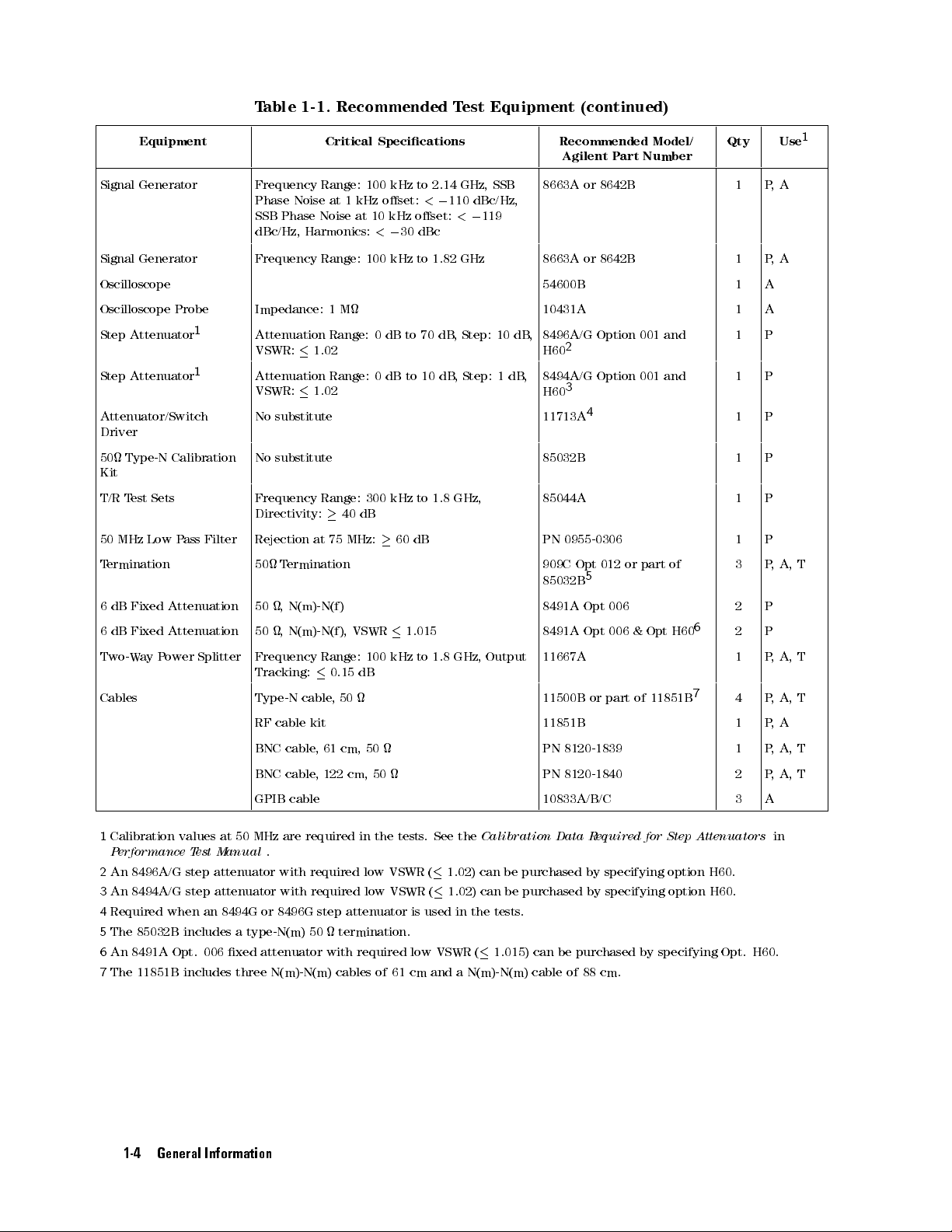
T
able 1-1.
Recommended T
est Equipment
(continued)
Equipment Critical
Signal Generator Frequency Range:
Phase
Noise
at
SSB
Phase
1
Noise
dBc/Hz, Harmonics:
Signal
Generator
Frequency
Range:
Specications
100 kHz
kHz
oset:
at 10
kHz oset:
<
0
30
100
kHz
to 2.14
<
0
dBc
to
1.82
110
<
GHz,
dBc/Hz,
0
GHz
119
SSB
Recommended
Agilent P
8663A or
8663A
or
8642B
8642B
art
Model/
Number
Qty Use
1 P,
1 P
Oscilloscope 54600B 1 A
Oscilloscope
Step
Step Attenuator
Probe
Attenuator
1
1
Attenuator/Switch
Impedance:
Attenuation
VSWR:
1
M
Range:
1.02
Attenuation Range:
VSWR:
1.02
No
substitute
0
dB
0dB
to
70
dB,
Step: 10
to
10
dB
,
Step:
10431A 1 A
dB,
1
dB
,
8496A/G
H60
8494A/G Option
H60
11713A
Option
001
2
3
and
001 and
4
1 P
1 P
1 P
Driver
50
Type-N
Calibration
No
substitute
85032B 1 P
Kit
T/R
T
est
Sets
Frequency
Directivity:
50
MHz
T
ermination
6
dB
Fixed
6
dB
Fixed
Two-W
ay
Low
P
ass
Attenuation
Attenuation
P
ower
Filter
Splitter
Rejection
50
T
50
,
50
,
Frequency
Tracking:
Cables Type-N
RF
cable
BNC
BNC
Range:
at
75
ermination
N(m)-N(f)
N(m)-N(f),
Range:
0.15
cable
,
kit
cable
,
61
cable
,
122
40
MHz:
VSWR
dB
50
cm,
cm, 50
dB
300
100
50
kHz
60
kHz
to
dB
1.015
to
1.8
1.8
GHz,
GHz,
Output
85044A 1 P
PN
0955-0306
909C
85032B
8491A
8491A
Opt
5
Opt
Opt
012
006
006
or
part
of
&
Opt
H60
1 P
3 P
2 P
6
2 P
11667A 1 P
7
11500B
or
part
of
11851B
4 P
11851B 1 P
PN
8120-1839
PN
8120-1840
1 P
2 P
GPIB cable 10833A/B/C 3 A
1
A
,
A
,
A,
T
,
A,
T
,
A,
T
,
A
,
A,
T
,
A,
T
1
Calibration
P
erformance T
2
An 8496A/G step attenuator with required low VSWR (
3
An 8494A/G step attenuator with
4
Required when an 8494G or 8496G step attenuator is used in the tests
5
The 85032B includes a type-N(m) 50 termination.
6
An 8491A Opt. 006 xed attenuator with required low VSWR (
7
The 11851B includes three N(m)-N(m) cables of 61 cm and a N(m)-N(m) cable of
values
est Manual
at
50
MHz
are
required
in
the
tests
.
See the
Calibration
.
1.02) can be purchased by
required low VSWR (
1.02) can be purchased by specifying option H60.
.
1.015) can be purchased by specifying Opt. H60.
1-4 General Information
Data
R
equired
for
Step
specifying option H60.
88 cm.
Attenuators
in
Page 31

T
able 1-1.
Recommended T
est Equipment
(continued)
Equipment Critical
Adapters BNC(f)-BNC(f) adapter
BNC(f)-SMA(f)
T
ee
BNC(m)-(f)-(f)
SMB(m)-SMB(m)
SMC(f)-BNC(f)
SMB(f)-BNC(f)
N(f)-BNC(f)
N(m)-N(m)
N(m)-BNC(f) adapter
N(f)-BNC(m)
adapter
adapter
adapter
adapter
adapter
adapter,
adapter
adapter
,
50
,50
,
SMA(m)-BNC(f) adapter
SMA(m)-SMA(f) right
APC3.5(m)-APC3.5(f)
1
The 85032B
includes
APC7.5-N(f)
BNC(f)-SMA(m)
two
APC7.5-N(f)
adapter
adapter
adapters
,
Specications
,50
,
50
,
50
,
50
,
50
,
50
50
50
,
50
angle adapter
adapter
,
50
50
50
.
Recommended
Agilent P
art
Model/
Number
Qty Use
1
PN 1250-0080 1 P
PN
1250-0562
PN
1250-0781
PN
1250-0813
PN
1250-0832
PN
1250-1236
PN
1250-1474
PN
1250-1475
PN 1250-1476 1 P,
PN
1250-1477
1 P
1 P
1 T
1 A
1 A
1 P
1 P
1 P
,
A
,
A
,A,
A, T
,
A,
T
T
PN 1250-1548 1 T
,
50
PN 1250-1741 1 A, T
PN
1250-1866
11524A
PN
1250-1548
or
part
of
85032B
1 P
,
1
1 P
1 A
A
General Information 1-5
Page 32

Page 33

A
djustments and
Introduction
This
chapter describes
that
the 4396B
adjustments
optimum
operating condition.
performance
are
performed, see
Note
Network/Spectrum/Impedance Analyzer
should be
cannot be
The
and
the A
performed along
achieved after
Chapter 3.
correction
then
operation.
Correction Constants
djustments and
The recommended
constants
recalled
to
rene
Correction
with periodic
the A
djustments and
are
empirically
the
analyzer's
Constants
is within
its specications
maintenance to
calibration period
Correction
derived
data
measurement
procedures
keep
is 12
months
Constants
that
is
and
required
the
analyzer
stored
to
dene
to
.
These
.
If
proper
procedures
in
memory
its
2
ensure
in
Safety
This
safety
adjustments
W
arning
The
accessible
Remember
Considerations
manual
of
contains
the
must
operator
be
Any
analyzer)
instrument
system
removal
by
that
or
opening
hand
the
NOTEs
and
,
to
performed
interruption
or
dangerous
for
any
of
covers
will
expose
capacitors
CA
UTIONs,
keep
by
of
and
the
instrument
qualied
the
protective
disconnection
.
Intentional
reason
circuits
in
the
is
for
adjustment,
containing
analyzer
W
ARNINGs
in
a
service
of
personnel.
the
protective
prohibited.
or
dangerous
can remain
that
safe
ground
interruption
removal
charged
through you have turned the analyzer OFF and unplugged it.
Warning
The adjustments described in this chapter are performed with power
applied and the protective covers removed. Dangerous voltage levels exist
at many points and can result in serious personal injury or death if you
come into contact with them.
must
and
serviceable
conductor
ground
of parts
voltage
be
followed
of
the
other than
levels
for
several
condition.
(inside
terminal
protective
.
minutes
to
The
or
outside
can
make
ground
those that
,
even
the
the
the
are
Adjustments and Correction Constants 2-1
Page 34

Required Equipment
T
able
1-1
lists
the equipment
procedures
analyzer
are
equal
W
arm-up
W
arm-up
A
djustments
instrument
described
.
If
the
to
,
the
operation.
in
recommended
or
surpasses
for
Adjustments
analyzer
and
Correction
this
for
chapter
those of
at
least
Constants
required to
.
Use only
test
equipment is
the recommended
and Correction
30
minute
procedures
perform the
calibrated test
not available
before
to
Adjustments
equipment when
, equipment
test equipment
Constants
performing
ensure
proper
and the
any of
results
Correction Constants
adjusting the
whose specications
may be
used.
the following
and
correct
Instrument
T
o
gain
access
covers
.
Order
When
in
the
40
520
CAL
Comb
Step
Second
DC
Of
performing
order
MHz
Reference
MHz
OUT
Generator A
Pretune
Local
Oset
0/90Tracking
Band
P
ass
Final
Gain
Source Mixer
RF OUT Level
Spectrum Analyzer Absolute Magnitude
Network Analyzer Absolute Magnitude
Cover
to
the
adjustment
A
djustments
more
than
they
appear
Oscillator
Level
A
djustment
Level
A
djustment
djustment
Correction
PLL
Lock
and
Hold
Step
A
djustment
Filters
A
A
djustments
djustment
Local Leakage A
Correction Constants
Removal
components
one A
in
this
chapter
Frequency
Constants
A
djustment
A
djustments
djustment
djustments
.
The
A
djustment
Correction Constants
Correction Constants
,
you
need
or
Correction
procedures
to remove
are
Crystal Filter Correction Constants
IF Gain Errors Correction Constants
Network Analyzer Magnitude Ratio/Phase Correction Constants
10 MHz Reference Oscillator Frequency A
djustment (Option 1D5 Only)
the top
Constants
presented
cover and
procedure
in
the
following
the
,
perform
side
them
order:
2-2 Adjustments and Correction Constants
Page 35

Updating Correction
This
section
adjustments
A
djustments Program
The
adjustments program
Agilent
provides
program.
part number
general
of
the
is
provided
adjustement
follows:
Constants using
information on
on
how to
one
double-sided
program.
the A
update the
The
les
djustments Program
Correction Constants
diskette
contained
.
Refer
on
to
the
T
able
diskette
using the
1-1
for
are
the
as
ADJ4396B
TE A4396B
Note
Keyboard
The menus
and mouse
Keyboard
1.
Press
2.
Choose
Nimitz
N
N
N
N
NN
If
N
QUIT
3.
press
displays another
Note
A
djustments
Equipment
T
o
prevent
copies
copies
only
for
and
Mouse
in \ADJ4396B"
operations
as
Operation
5
5
,
4
9
the
highlighted
keys
4
8
Keyboard).
N
N
N
N
NN
N
N
N
N
N
N
45
N
N
N
N
or
EXIT
(
4
CONTINUE
N
N
N
N
N
menu.
Press
4
?
highlighted.
Program
Conguration
accidental
of
the furnished
for
daily use
making
Operation
use
a
follows:
until
your
item
is
displayed
5
,
if
Nimitz
5
to
access
Help
deletion
master diskette
.Keep
working
window
preference
by
pressing
in
a
menu,
Keyboard)
on-screen
information
Program
or
the master
copies.
format.
is
highlighted.
4
RETURN
select
to
help
appears
destruction of
(HFS or
diskettes in
The
window
5
or
4
SELECT
one
of
these
exit.
When
you
information
in
a
display
the program,
SRM system).
a
safe
format
for
5
(
to
exit
the
menu
4
ENTER
exit
menus
selection
window
make working
Use
place
and
supports
5
or
4
EXECUTE
the
menu.
,
the
you
.
the
working
use
them
keyboard
5
,
if
Otherwise
program
have
,
Mouse
Press
the
Operation
4
RETURN
help
5
screen.
or
4
SELECT
5
(
4
ENTER
5
or
4
EXECUTE
5
,
if
Nimitz
1. Slide the mouse up or down until your preference is highlighted.
2. Choose the highlighted item by pressing left-hand button on the mouse
to the right.
NNNNNNNNNNNNNN
3.
If
QUIT
slide the mouse to the left to exit. When you exit menus
or
NNNNNNNNNNNNNN
EXIT
is displayed in a menu, select one
of these to exit the menu. Otherwise
, the program displays
menu.
Note
Press the right-hand mouse button to access on-screen help information for the
selection you have highlighted. Help information appears in a display window.
Press the left-hand mouse button to turn o the help screen.
Adjustments and Correction Constants 2-3
Keyboard)
to
turn
, or slide the mouse
another
o
,
Page 36

Controller
The
following
Requirement
controller
system
is
required
to
run
the
adjustments
program.
Controller
Mass
Storage
The
controller
language
HP
Excluding
Must
At
At
HFS
must
extension
9000
Series
have
least
4
least
one
formatted
be
equipped
les
listed
Name V
HP
9826A
inverse
M
bytes
3.5
in T
200/300
video
of
inch
hard
disk
with
able 2-1
T
able
ersion
computer
computers
capability
RAM
GPIB
Flexible Disk
system
HP
B
ASIC versions
.
2-1.
Required
or
SRM
Binaries
Description
Drive
system
between 5.1
GRAPH 5.2 Graphics
GRAPHX 5.2 Graphics
Extensions
IO 5.1 I/O
MA
T
5.1 Matrix
Statements
PDEV 5.0 Program Development
KBD 5.1 Keyboard
Extensions
CLOCK 5.0 Clock
MS 5.1 Mass
ERR 5.1 Error
DISC 5.0 Small
CS80 5.0 CS80
GPIB 5.0 GPIB
FGPIB 5.0 GPIB
CRTB 5.2 Bit-mapped CRT
CRT
A
5.1 Alpha
CRTX 5.1 CRT
EDIT 5.1 List
SRM 5.1 Shared
DCOMM 5.0 Datacomm
HFS 5.3 Hierarchical File
Storage
Message
Disc Driver
Disc
Driver
Interface
Interface
CRT
Driver
Extensions
and
Edit
Resource
Interface
Driver
Driver
Driver
Management
System
COMPLEX 5.1 Complex Arithmetic
are supported.
and 5.13,
Driver
and the
2-4 Adjustments and Correction Constants
Page 37

Updating
Correction
Constants
Correction
1.
Connect
Constants
the
equipment
are
Figure
updated
as
shown
2-1.
using
in
Updating
the
following
Figure
procedure:
2-1
Correction
Constants
Setup
Steps
2
to
5
are
used
to
select
the
Note
2.
Locate the
the
3.
Set the
where
4.
Load
When
steps
\TE A4396B"
GPIB
Equipment
directly where
mass storage
A4396B"
\TE
and
run
\TE
you
perform
to
select
address
Conguration
the
A
unit
is located.
A4396B".
the
the
equipment
program
.
djustment
specier
A
djustments
only
Program
Program
(MSUS)
equipment
and
the
when
you
\TE
\ADJ4396B"
to
the
Program
GPIB
want
A4396B"
address
5. Follow the instructions on the controller's screen until the program ends
and
the
rst
address
to
change
in the
will
of
the
to
set
time
.
After that,
the
address
be
run.
drive
their
GPIB
, perform
equipment
or
the
.
addresses
these
perform
of
the
directory
the
or the
drive
6. Set the mass storage unit specier (MSUS) to the address of the drive or the directory
where the A
djustment Program \ADJ4396B" is located.
7. Load and run \ADJ4396B".
8. A window format menu is displayed.
9. Choose \INITIAL SETUP" if you want to
update the Calibrated V
alue for the power sensor
10. Choose the item that you want to perform.
11. Follow the instruction on the controller's screen until the program ends. The equipment
connections are shown in each Correction Constants procedure in this chapter.
.
or
.
Adjustments and Correction Constants 2-5
Page 38

40 MHz
The
purpose
Reference Oscillator
of
this
procedure is
to adjust
Frequency A
the 40
MHz reference
djustment
oscillator frequency
.
Required
Frequency
BNC
cable
Procedure
1.
Connect the
Equipment
Counter
,
61
cm
:
:
:
:
:
:
equipment as
:
:
:
:
:
:
:
:
:
:
:
:
::
::
::
shown in
:
:
:
::
::
::
::
:
:
:
:
:
:
:
:
:
:
:
:
:
:
:
:
:
::
::
::
::
:
:
:
:
:
:
:
:
:
:
:
:
:
5343A
:
:
:
:
:
:
:
:
:
:
:
:
:
:
:
:
:
:
:
::
::
::
:
:
:
:
:
:
:
:
:
:
:
:
:
:
:
:
:
:
:
::
::
::
Figure
2-2
.
:
:
PN
Option
8120-1839
001
2.
Set
the
Input
Frequency
Figure
frequency
Impedance
2-2.
counter
Range
40
50
10
MHz
Hz
Reference
as follows:
-
500 MHz
Oscillator
Frequency
A
djustment
3. Adjust A5 \40 MHz FREQ ADJ" until the frequency counter reading is within
20 MHz
6
2 Hz. The adjustment location is shown in Figure 2-4.
2-6 Adjustments and Correction Constants
Setup
Page 39

Figure 2-3.
40 MHz
Reference Oscillator
Frequency A
djustment
Location
Adjustments and Correction Constants 2-7
Page 40

520 MHz
The
purpose
Level A
of
this
procedure is
djustment
to adjust
the 520
MHz output
level.
Required
Spectrum
SMC(f)-BNC(f)
N(m)-BNC(f)
BNC
cable
Procedure
1.
Turn the
2.
Remove the
shown
in Figure
Equipment
Analyzer
:
:
:
adapter
adapter
,
61
cm
analyzer
\J"
:
:
:
OFF
cable
2-4
.
:
:
:
:
:
:
:
:
:
:
.
from
:
:
:
:
:
:
:
:
::
::
::
::
:
:
:
:
:
:
:
:
:
:
:
:
:
:
:
:
:
::
::
::
::
:
:
:
:
:
:
:
:
:
:
:
:
:
:
:
:
:
::
::
::
:
8566A/B
:
:
:
:
:
:
:
:
:
:
::
::
::
:
:
:
:
:
:
:
:
:
:
:
:
:
:
:
:
:
:
:
::
::
::
:
:
:
:
:
:
:
:
:
:
:
:
:
:
:
:
:
:
PN
1250-0832
:
:
:
:
:
:
:
:
::
::
::
:
:
:
:
:
:
:
:
:
:
:
:
:
:
:
:
:
:
:
::
::
::
:
:
:
:
:
:
:
:
:
:
:
:
:
:
:
:
:
:
:
:
PN
1250-1476
:
::
::
::
:
:
:
:
:
:
:
:
:
:
:
:
:
:
:
:
:
:
:
::
::
::
:
:
:
:
:
:
:
:
:
:
:
:
:
:
:
:
:
:
:
::
::
::
:
:
PN
8120-1839
the
A5
\520
MHz
OUT"
connector
.
The
connector
location
is
Figure
3.
Connect the equipment as shown in Figure 2-5.
2-4. 520
MHz Level
2-8 Adjustments and Correction Constants
Adjustment
Location
Page 41

4.
Set
the
spectrum
Figure 2-5.
analyzer
as
follows:
520 MHz
Level A
djustment Setup
CENTER
SP
AN
RBW
5.
Turn
the
6.
A
djust
level
is
7.
Turn the
8.
Reconnect the
4396B
A5
\520
within
4396B
Frequency
analyzer
MHz LEVEL
0
15
6
0.2
analyzer
\J"
cable
520
MHz
1
MHz
100
kHz
ON.
ADJ" until
dBm.
OFF
.
to
the
The
A5
\520
the
spectrum
adjustment
MHz
OUT"
location
connector
analyzer
is
shown
reading
.
in
for
Figure
520
2-4
MHz
.
signal
Adjustments and Correction Constants 2-9
Page 42

CAL OUT
The
purpose
Level A
of
this
procedure is
djustment
to adjust
the CAL
OUT level.
Required
P
ower
Meter
P
ower
Sensor
N(f)-BNC(m)
Procedure
1.
Connect the
sensor
.
2.
Connect the
Equipment
:
:
:
:
:
:
:
:
:
:
:
:
:
:
:
:
:
:
:
adapter
:
power sensor
equipment
:
:
:
::
:
:
::
:
as
::
::
::
::
:
:
:
:
to the
shown
:
:
::
:
:
:
:
:
:
:
:
:
:
::
::
power
in
:
:
:
:
:
:
::
:
Figure
:
:
:
:
:
:
:
:
:
:
:
:
:
:
meter
:
:
:
:
:
:
2-6
:
:
:
:
:
:
:
::
:
:
:
:
:
.
Calibrate
.
::
::
:
::
::
::
:
:
:
:
:
:
:
:
:
:
:
:
:
:
:
:
:
::
::
::
::
:
:
:
:
:
:
:
:
:
:
436A
::
:
:
:
:
:
:
:
:
:
:
:
:
:
:
:
:
:
:
:
::
::
::
:
:
:
:
:
:
:
:
:
:
:
:
8482A
:
:
:
:
:
:
::
::
::
:
:
:
:
:
:
:
:
:
:
:
:
:
:
:
:
:
:
:
:
PN
1250-1477
the
power
meter
for
the
power
Figure
3. A
djust A5 \CALIBRA
0
2060.2 dBm . The adjustment location is shown in Figure 2-7.
TOR LEVEL ADJ" until the power meter reading is within
2-6.
CAL
OUT
Level
A
2-10 Adjustments and Correction Constants
djustment
Setup
Page 43

Figure 2-7.
CAL OUT
Level A
djustment Location
Adjustments and Correction Constants 2-11
Page 44
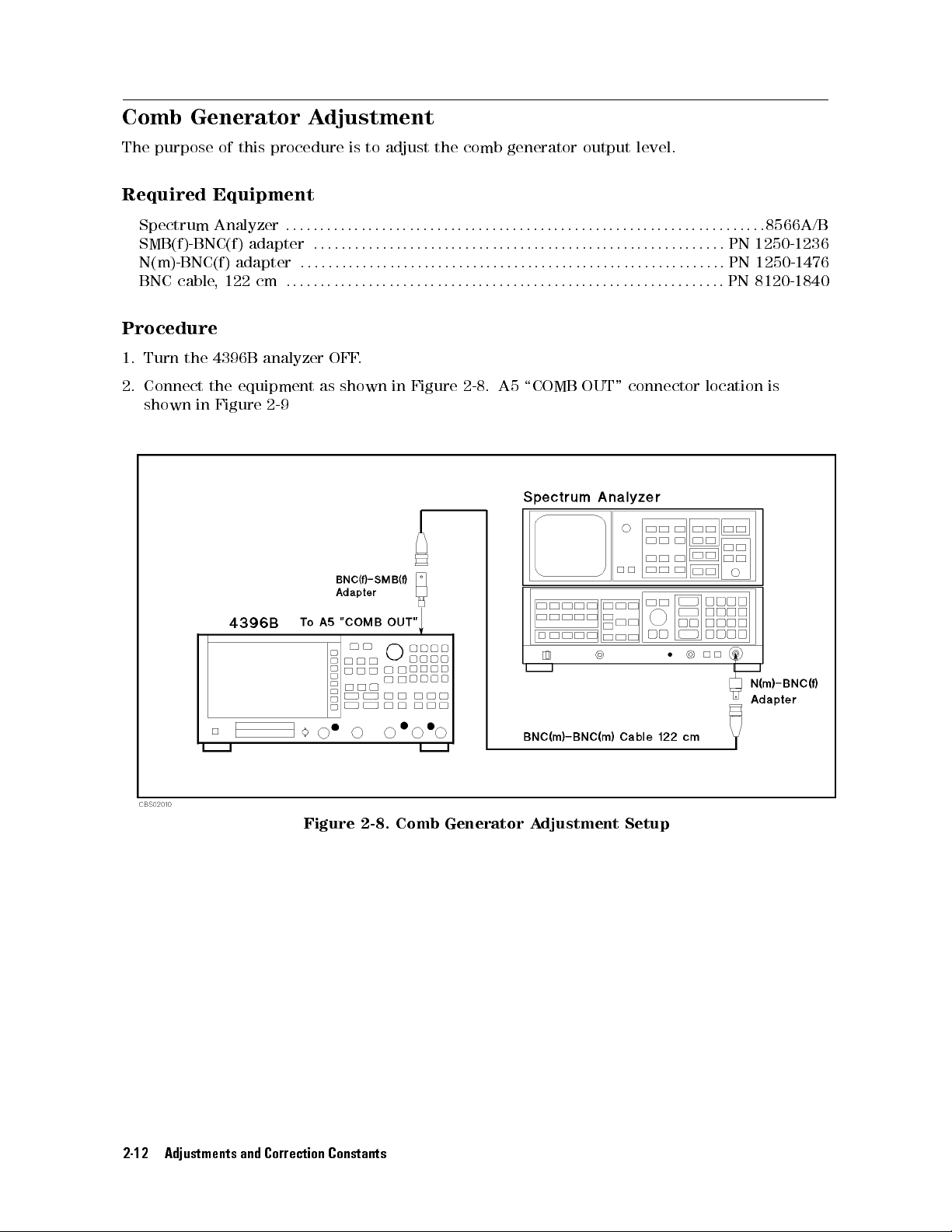
Comb Generator
The
purpose
of
this
procedure is
Adjustment
to adjust
the comb
generator output
level.
Required
Spectrum
SMB(f)-BNC(f)
N(m)-BNC(f)
BNC
cable
Procedure
1.
Turn the
2.
Connect the
shown
in Figure
Equipment
Analyzer
:
:
:
adapter
adapter
,
122
4396B
cm
:
:
analyzer
:
:
equipment
2-9
:
:
:
:
:
:
:
:
:
:
:
as
:
:
:
:
:
:
:
:
:
:
:
:
:
:
::
OFF
shown
:
:
:
::
:
:
::
::
::
::
:
:
:
:
:
:
:
:
:
:
:
:
:
:
:
:
:
::
::
::
::
:
:
:
:
:
:
:
:
:
:
:
:
:
:
:
:
:
::
::
::
:
8566A/B
:
:
:
:
:
:
:
:
::
::
::
:
:
:
:
:
:
:
:
:
:
:
:
:
:
:
:
:
:
:
::
::
::
:
:
:
:
:
:
:
:
:
:
:
:
:
:
PN
1250-1236
:
:
::
::
::
:
:
:
:
:
:
:
:
:
:
:
:
:
:
:
:
:
:
:
::
::
::
:
:
:
:
:
:
:
:
:
:
:
:
:
:
:
:
:
:
:
:
PN
1250-1476
::
:
:
:
:
:
:
:
:
:
:
:
:
:
:
:
:
:
:
:
::
::
::
:
:
:
:
:
:
:
:
:
:
:
:
:
:
:
:
:
:
:
::
::
::
PN
8120-1840
.
in
Figure
2-8
.
A5
\COMB
OUT"
connector
location
is
Figure
2-8.
2-12 Adjustments and Correction Constants
Comb
Generator
A
djustment
Setup
Page 45
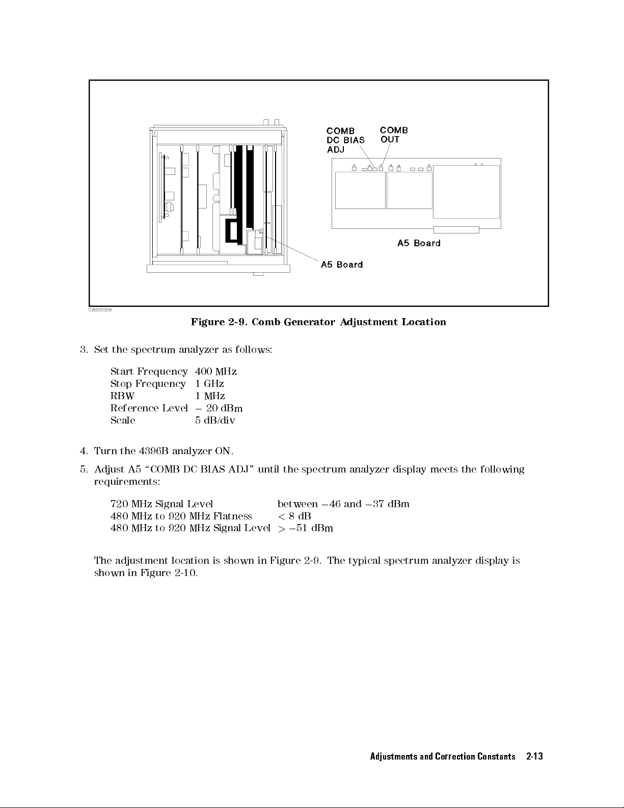
3.
Set
the
Start
Stop
RBW
Reference
Scale
4.
Turn
the
5.
Adjust
requirements:
spectrum
Frequency
Frequency
Level
4396B
A5
\COMB
Figure 2-9.
analyzer
400
1
GHz
1
MHz
0
5
dB/div
analyzer
DC
BIAS
20
as
MHz
dBm
ON.
ADJ"
Comb Generator
follows:
until
the
spectrum
Adjustment
analyzer
Location
display
meets
the
following
720 MHz
480 MHz
480
Signal Level
to 920
MHz
to
MHz Flatness
920
MHz
The adjustment location
shown in Figure
2-10.
Signal
Level
between
<
8
>
0
dB
51
0
dBm
46
and
0
37
dBm
is shown in Figure 2-9. The typical spectrum analyzer display is
Adjustments and Correction Constants 2-13
Page 46

Figure 2-10.
Comb Generator
Output
2-14 Adjustments and Correction Constants
Page 47
Step Pretune
The
the
purpose
step
loop
of
this
oscillator
Correction Constants
procedure is
to generate
the correction
.
constants that
are used
to pretune
Required
None
Procedure
1.
Run the
Constants
2.
Choose the
3.
F
ollow
the
Equipment
adjustment program
using the
Step Pretune
adjustment
Adjustments
Correction
program
and
display
Program
Constants
instructions
the
").
main
.
to
menu
update
(see
the
correction
\Updating
constants
Correction
.
Adjustments and Correction Constants 2-15
Page 48

Second Local
The
purpose
of
this
PLL Lock
procedure is
Adjustment
to lock
the second
local Phase
Lock Loop
(PLL).
Required
Equipment
Spectrum Analyzer
BNC(f)-SMA(m) adapter
N(m)-BNC(f)
BNC
cable
adapter
,
122
cm
Procedure
1.
Turn
the
4396B analyzer
2.
Remove the
A3A2
\Second Local
\D" cable
:
:
:
:
:
:
:
:
:
:
:
:
:
:
:
:
:
:
:
:
:
:
:
:
:
:
:
:
:
:
:
:
:
:
:
:
:
:
:
:
:
:
:
:
::
OFF.
from the
Out" connector
:
:
:
:
:
:
:
:
:
:
:
::
::
A3A1
::
::
:
:
:
:
::
::
:
:
.The
::
::
:
:
:
:
::
:
:
:
:
:
\ALC
::
:
:
:
:
:
:
:
:
:
:
:
::
::
:
:
:
:
:
:
:
:
:
:
:
:
:
:
:
:
:
:
:
:
:
Out"
connector
connector
:
:
:
:
:
:
:
:
:
:
:
:
:
:
:
:
:
:
:
::
locations
:
:
:
::
:
:
:
:
:
:
::
::
::
:
:
:
:
::
::
:
:
:
.
Remove
are
::
:
:
::
:
::
:
:
::
:
:
:
:
:
:
:
:
:
::
::
:
:
:
:
:
:
:
:
:
:
the
shown
:
:
:
:
:
:
:
:
:
:
:
:
::
:
8566A/B
:
:
:
:
:
:
:
:
:
PN
1250-1548
:
:
:
:
:
:
:
:
:
PN
1250-1476
:
:
:
:
:
:
:
::
PN 8120-1840
\I"
cable
from
the
in
Figure
2-11
.
Figure 2-11.
Second Local
3. Connect the equipment as shown in Figure 2-12.
2-16 Adjustments and Correction Constants
PLL
A
djustment
Location
Page 49

4.
Set
the
spectrum
Figure 2-12.
analyzer
as
follows:
Second Local
PLL A
djustment Setup
Center
Span
RBW
5.
Turn
6.
Press
4
PRESET
7.
A
djust
display
rotate
counterclockwise
8.
Turn
9. Reconnect the \I" cable to
the
4396B
the
following
5
,
4
SYSTEM
A3A2
and
\Second
the
analyzer
Frequency
analyzer
N
5
,
\Second
the
4396B
Local
.
The
OFF
2.08
400
1
MHz
ON.
keys
to execute
N
N
N
N
N
N
NN
NN
N
N
N
N
N
N
N
SERVICE
Local
analyzer
A
dj"
adjustment
.
GHz
MHz
N
N
N
N
N
N
N
N
N
N
N
N
N
N
NN
MENU
A
dj"
reading
clockwise
the A3A2 \Second Local Out" connector
cable to the A3A1 \ALC Out" connector
adjust test
N
N
N
N
N
N
N
NN
N
N
TESTS
,
until
2.08
.
If
location
NN
NN
N
N
N
N
N
N
,
4
4
GHz
is
between
1.92 GHz
is
.
No
.44:
5
5
,
,
4
4
appears
appears,
shown
N
N
N
N
EXECUTE
5
,
4
x1
constantly
the limit
in
Figure 2-11
N
N
N
NN
NN
N
N
N
N
N
N
N
N
N
N
N
N
N
N
N
N
N
N
N
N
N
NN
NN
TEST
on
lines.
If 2.24
rotate \Second
.
. Reconnect the \D"
N
N
the
GHz
Local A
spectrum
appears
dj"
analyzer
,
Adjustments and Correction Constants 2-17
Page 50

DC Oset
The
purpose
output.
and Hold
of
this
procedure is
Step A
to minimize
djustment
the hold
step and
DC oset
of the
sample hold
Required
Oscilloscope
10:1
Divider
Procedure
1.
Turn the
2.
To
gain
side
.
3.
Pull
the
upward.
4.
Remove
5.
Pull
the plugs
going
to
Equipment
:
:
:
:
:
:
:
:
:
Probe
,
1
analyzer
access
A6
board
the
to
shield
OFF
the
out.
case
that block
do the
/90tracking
0
:
:
:
::
::
::
M
:
:
:
:
.
adjustment
Place
from
the \DC
:
:
:
:
:
:
:
:
:
:
:
::
::
::
components
the
board
the
board.
OFFSET ADJ"
adjustment,
:
:
:
:
:
:
:
:
:
:
:
::
::
::
:
:
:
:
:
:
:
:
:
:
:
:
:
:
:
:
:
:
:
::
::
::
:
:
:
:
:
:
:
:
:
:
54600B
:
:
:
:
:
:
:
:
:
:
:
:
:
:
:
:
:
:
:
::
::
::
:
:
:
:
:
:
:
:
:
:
:
:
:
:
:
:
:
:
:
::
::
::
:
10431A
,
on
remove
the
analyzer
pull the
holes
other two
the
out
side
with
(see
panel
the
component
Figure
plugs out.
on
2-13
the
control
side
).
If
facing
you
keys
are
also
Figure 2-13. Plug Locations
6. Replace the shield case on the A6 board. Replace the A6 board into
the slot.
7. Connect the equipment as shown in Figure 2-14 to monitor the sample hold output signal.
Test pins locations are shown in Figure 2-15 .
2-18 Adjustments and Correction Constants
Page 51
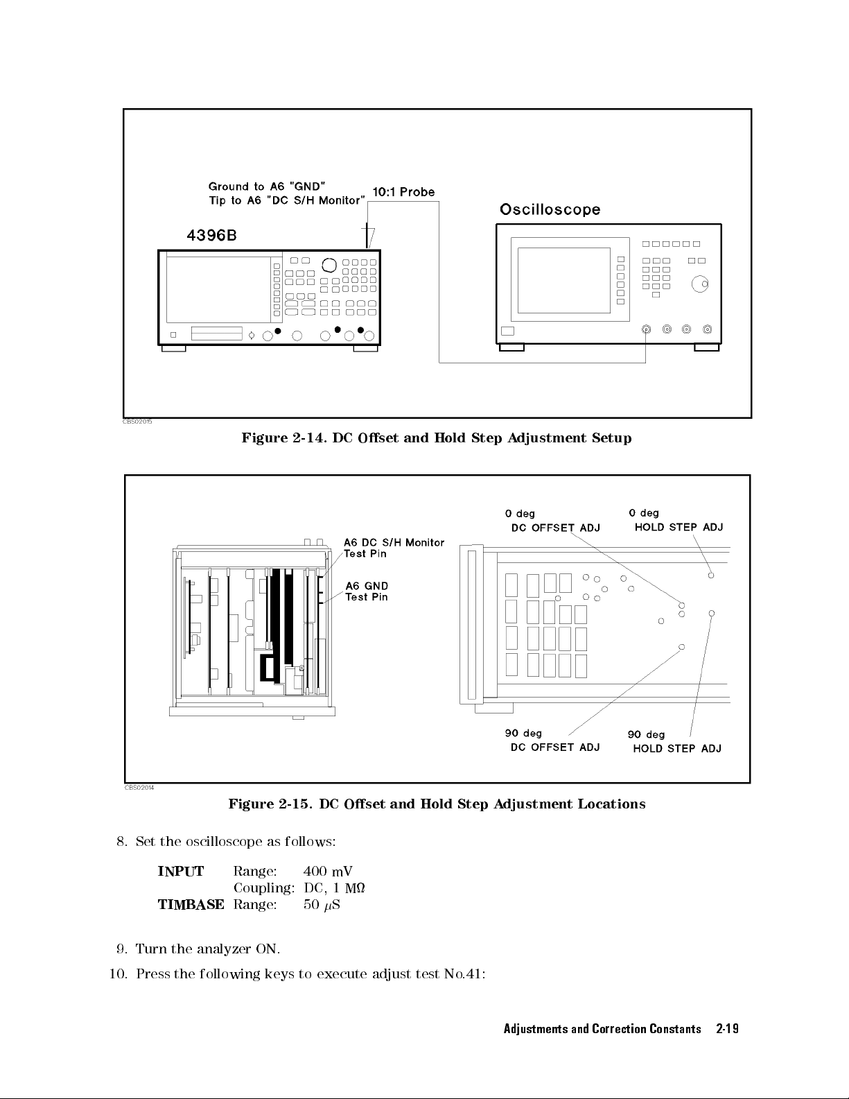
Figure 2-14.
DC Oset
and Hold
Step A
djustment
Setup
Figure 2-15. DC Oset
8. Set the oscilloscope as follows:
INPUT
TIMBASE
9. Turn the analyzer ON.
10. Press the following keys to execute adjust test No.41:
Range: 400 mV
Coupling: DC, 1 M
Range: 50S
and Hold Step A
djustment Locations
Adjustments and Correction Constants 2-19
Page 52

4
PRESET
11. A
is within
Figure 2-15
Note
5
djust \0
,
4
SYSTEM
deg DC
0
6
25 mV
.
If
the
oscilloscope
N
N
N
N
N
N
N
N
N
N
NN
NN
NN
NN
NN
NN
SERVICE
5
,
NN
OFFSET ADJ"
as shown
waveform
range
N
N
N
N
N
N
N
N
N
N
N
NN
N
MENU
until the
in Figure
doesn't
setting
N
N
N
N
N
TESTS
,
appear
to
N
N
N
N
N
NN
NN
NN
N
,
5
5
,
4
4
1
4
,
4
x1
N
EXECUTE
5
,
oscilloscope waveform's
2-16.
The
adjustment
on
the
oscilloscope
4
V
to
adjust
coarsely
N
N
N
N
N
N
N
N
N
NN
NN
NN
NN
NN
NN
NN
location
display
.
N
N
N
N
N
N
N
N
N
N
TEST
longer
N
NN
N
step
is
shown
,
change
voltage
in
the
12.
A
djust
shorter
shown
\0
step
in
deg
HOLD
is
Figure
smaller
2-15
Figure
STEP
than
.
2-16.
ADJ"
50
mV
DC
until
,
as
Oset
the
voltage
shown
A
djustment
dierence
in
Figure
2-17
W
aveform
between
.
The
the
longer
adjustment
step and
location
is
2-20 Adjustments and Correction Constants
Page 53

13.
Press
14.
A
djust
adjustments
15.
Press
Note
16.
Turn
17.
Pull
upward.
N
N
N
N
N
N
N
N
N
N
N
N
N
N
CONT
to
\90
deg
.
N
N
N
N
N
N
N
N
N
N
N
N
N
N
CONT
to
Steps
going
the analyzer
the A6
board out.
proceed
HOLD
nish
the
16
to
to
do
OFF.
Figure 2-17.
to
the
adjustments
STEP
ADJ"
adjustment.
19
replace
/90tracking
the
0
Place the
Hold Step
and
\90
the
plugs
board on
Adjustment
into
90
DC
the \DC
.
OFFSET
for
deg
adjustment,
the
analyzer
Waveform
ADJ"
OFFSET
skip
these
with
the
the
component
same
ADJ"
steps
holes
.
as
the
.
side
If
you
facing
0
deg
are
18. Replace
the plugs
into the
\DC
OFFSET
ADJ"
holes
see
Figure
2-18
.
Adjustments and Correction Constants 2-21
Page 54

19.
Replace
the
A6
board
into
Figure 2-18.
the slot.
Plug Locations
2-22 Adjustments and Correction Constants
Page 55

0/90Tracking A
The
purpose
measurement
of
this
circuit
procedure is
and
Required Equipment
djustment
to minimize
measurement
90
the dierence
circuit.
between the
third IF
0
N(m)-BNC(f)
BNC
cable
Procedure
1.
Turn
the
2.
T
o
gain
side
.
Note
3.
Pull
the
upward.
4.
Remove
5.
Pull
the
adapter
,
61
analyzer
access
Steps
plugs
A6
board
the
shield
plugs
cm
to
that
:
:
:
:
:
:
:
::
OFF
the
adjustment
3
to
are
out.
case
block
:
:
:
:
:
:
::
::
:
.
6
pull the
already
Place
from
the
::
::
:
:
:
out,
the
the
\TRA
::
:
:
:
:
:
:
:
:
:
:
:
:
:
:
:
:
:
:
:
:
:
:
:
components
plugs that
skip
these
board
on
board.
CKING
ADJ"
:
:
:
:
:
:
:
:
:
::
:
:
::
::
::
:
:
:
,
remove
block
the
steps.
the analyzer
holes
::
::
:
:
:
:
:
the
\TRA
with the
(see
:
:
:
:
:
:
:
:
side
CKING
Figure
:
:
:
:
:
:
:
:
:
:
:
:
:
:
:
:
:
:
::
::
panel
on
ADJ"
component side
2-19
).
:
:
::
the
:
:
::
::
PN 1250-1476
:
:
:
:
:
PN
control
holes
out.
8120-1839
keys
If
these
facing
Figure 2-19. Plug Locations
6. Replace the shield case on the A6 board. Replace the A6 board into the slot.
7. Turn the analyzer ON.
8. Connect the equipment as shown in Figure 2-20
Adjustments and Correction Constants 2-23
Page 56

9.
10.
Press
4
PRESET
A
djust
reading
shows
the
following
5
,
4
SYSTEM
\PHASE"
of
magnitude
the
adjustments
Figure 2-20.
keys
N
N
N
N
N
N
N
N
NN
NN
N
N
SERVICE
5
,
and
\GAIN"
is
smaller
limit.)
0
to
execute adjust
N
N
N
N
N
N
N
N
N
N
N
N
N
N
N
N
N
N
N
NN
NN
N
MENU
,
of
\0/90
than
A
djustment
/90Tracking A
N
N
N
N
N
N
N
N
NN
TESTS
deg
0.1
test No
NN
N
N
N
N
N
,
TRA
U
.
5
4
4
(The
.42:
5
,
4
2
CKING
smallest
locations
djustment Setup
N
N
N
N
N
N
N
N
NN
NN
N
N
N
N
N
EXECUTE
5
,
,
4
x1
ADJ"
until
circle
are
shown
in
N
N
N
N
N
N
N
N
N
N
TEST
the
of the
Figure
N
N
N
N
N
N
NN
NN
N
analyzer's
analyzer
2-21
marker
display
.
Figure 2-21. 0/90Tracking Adjustment Locations
Press
NNNNNNNNNNNNNN
CONT
to nish the adjustment.
11.
2-24 Adjustments and Correction Constants
Page 57
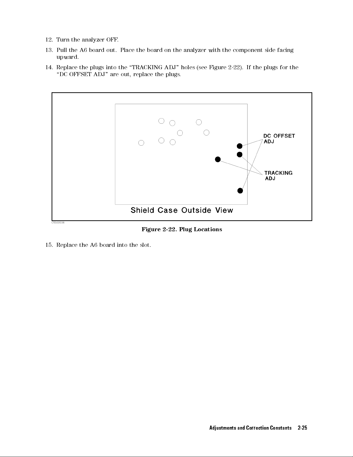
12.
Turn the
13.
Pull the
upward.
14.
Replace the
\DC
analyzer OFF
A6 board
plugs into
OFFSET ADJ"
.
out. Place
the \TRA
are out,
the
board
CKING
replace the
on
the
ADJ"
plugs
analyzer
holes
.
(see
with
Figure
the
component
2-22
side
facing
).
If
the
plugs
for
the
15.
Replace
the
A6
board
into
the
Figure
slot.
2-22.
Plug
Locations
Adjustments and Correction Constants 2-25
Page 58

Band P
The
purpose
ass Filters
of
this
procedure is
Adjustments
to optimize
the 1
MHz and
3MHz
Band P
ass Filters
.
Required
N(m)-BNC(f)
BNC
cable
Procedure
3
MHz
Band
1.
Turn
the
2.
T
o
gain
side
.
3.
Connect
Equipment
adapter
,
61
cm
:
:
:
P
ass
Filter
analyzer
access
the
OFF
to
the
equipment
:
:
:
:
:
:
:
:
:
:
:
:
:
::
::
A
djustment
.
adjustment
as
shown
:
:
:
:
:
::
:
:
:
::
::
::
::
:
:
:
:
:
:
:
:
:
:
:
:
:
components
in
Figure
:
:
:
:
2-23
:
:
:
:
:
:
:
,
remove
:
:
:
:
:
:
:
:
:
::
::
::
::
:
:
:
:
:
:
:
:
:
:
:
:
:
:
:
:
PN
1250-1476
::
::
::
:
:
:
:
:
:
:
:
:
:
:
:
:
:
:
:
:
:
:
::
::
::
:
:
PN
8120-1839
the
side panel
on the
control keys
Figure 2-23. Band P
4. Turn the analyzer
ON.
5. Press the following keys
NNNNNNNNNN
SERVICE MENU
5
4
PRESET
6. A
djust \BW"s of
5
,
4
SYSTEM
,
\3 MHz BPF ADJ" until the analyzer measurement trace is within the
to execute adjust test No
NNNNNNNNNNNNNNNNNNNNNNNNN
NNN
ass Filters A
NNNNNNNNNN
NNNNNNN
TESTS
,
djustments Setup
.46:
NNNNNNNNNN
,
4
4
4
4
x1
6
NNNNNNNNNNNNNNNNNNNNNNNNN
EXECUTE TEST
5
,
5
,
5
,
NNN
limits and \PASS" is displayed. The adjustment locations are shown in Figure 2-24.
2-26 Adjustments and Correction Constants
Page 59

7.
8.
Press
A
djust
width)
N
N
N
N
N
N
N
N
N
N
CONT
\BW"s
and
N
N
N
N
to
marker
Figure 2-24.
continue
of
the
\3
frequency
the
MHz
3
BPF
MHz
meet
Band P
band
ADJ"
the
ass Filters
pass
lter
until
the
following
Adjustment
adjustment.
analyzer
readings
requirements
Locations
of
\BW"
and
\P
ASS"
(
0
3
dB band
is displayed.
BW
Marker
9.
Press
10.
A
djust
between
Figure
11.
Press
1
MHz
BPF
12. Press the
4
PRESET
13. A
djust \BW"s of \1 MHz BPF ADJ" until the analyzer measurement trace is within the
limits and \P
14.
Press
Frequency
N
N
N
N
N
N
N
N
N
NN
NN
N
CONT
to
continue
\GAIN"
0
2-24
N
NN
N
N
N
N
N
CONT
1
6
.
N
N
N
N
N
N
to
Band
of
0.1
nish
Width A
following keys to execute adjust test No
5,4
SYSTEM
ASS" is displayed. The adjustment locations are shown in
NNNNNNN
NNNNNNN
CONT
to continue the 1 MHz band pass lter adjustment.
3
MHz
20
MHz
the
\3
MHz
BPF
dBm
and
the
3
MHz
djustment
NNNNNNN
NNNNNNNNNNNNNNNNNNNNNNNNN
SERVICE MENU
5
,
6
0.27
6
0.18
3
MHz band
ADJ"
\P
ASS"
band
NNNNNN
MHz
MHz
until
is
displayed.
pass
NNNNNNN
NNNNNNNNNN
TESTS,4
,
pass lter
the
analyzer
lter
adjustment.
5,4
4
adjustment.
reading
The
adjustment
.47:
NNNNNNN
5
,
5,4
x1
7
of
marker
location
NNNNNNNNNNNNNNNNNNNNNNNNN
NNNNNN
EXECUTE TEST
magnitude
is
shown
Figure 2-24.
is
in
15. Adjust \BW"s of the \1 MHz BPF ADJ" until the analyzer readings of \BW" (03dBband
width) and marker frequency meet the following requirements and \PASS" is displayed.
BW 1 MHz60.12 MHz
Marker Frequency 20 MHz60.06 MHz
Adjustments and Correction Constants 2-27
Page 60

16.
17.
18.
N
NN
N
CONT
Press
Adjust
between
Figure
NN
NN
CONT
Press
NN
NN
NN
NN
NN
to continue
\GAIN" of
0
1
6
0.1
2-24.
NN
NN
N
N
N
N
N
N
to
nish the
the 1
\1 MHz
dBm and
MHz band
BPF
\P
1MHz
ADJ"
until
ASS"
is
band pass
pass lter
the
analyzer
displayed.
lter
adjustment.
reading
The
adjustment
adjustment.
of
marker
location
magnitude
is
shown
is
in
2-28 Adjustments and Correction Constants
Page 61

Final Gain
The
purpose
of
Adjustment
this
procedure is
to adjust
the total
gain of
the receiver
.
Required
Signal
BNC
Generator
cable
N(m)-BNC(f)
Procedure
1.
Connect the
Equipment
:
:
:
:
:
,
61
cm
(2
required)
adapter
:
equipment as
:
:
:
:
:
:
:
:
:
:
:
::
:
:
:
:
:
:
shown in
::
::
::
:
:
:
:
:
:
:
:
:
:
:
:
:
:
:
:
:
::
::
::
::
:
:
:
:
:
:
:
:
:
:
:
:
:
:
:
:
:
::
::
::
::
:
:
:
3335A
:
:
:
:
:
:
:
:
:
:
::
::
::
:
:
:
:
:
:
:
:
:
:
:
:
:
:
:
:
:
:
:
::
::
::
:
:
:
:
:
:
:
:
:
:
:
PN
8120-1839
:
::
::
::
:
:
:
:
:
:
:
:
:
:
:
:
:
:
:
:
:
:
:
::
::
::
:
:
:
:
:
:
:
:
:
:
:
:
:
:
:
:
:
:
:
:
PN
1250-1476
Figure
2-25
.
2.
Press
4
PRESET
the
5
,
following
4
SYSTEM
keys
NN
N
N
N
N
SERVICE
5
,
Figure
N
N
N
N
N
N
N
to
NN
NN
execute
NN
NN
NN
NN
NN
N
N
MENU
2-25.
N
N
N
N
N
N
N
adjust
NN
N
N
,
Final
N
N
N
N
N
N
N
N
N
N
TESTS
N
NN
test
NN
,
Gain
No
5
,
4
4
A
djustment
.43:
5
,
4
4
3
3. Set the signal generator as follows:
Frequency
Amplitude
4. A
djust \FINAL GAIN ADJ" until the analyzer reading is
20 MHz
0dBm
displayed. The adjustment location is shown in Figure 2-26.
Setup
NN
N
N
N
N
N
N
N
N
N
N
N
NN
NN
NN
NN
NN
NN
NN
N
N
N
N
N
N
N
N
N
N
x1
5
,
EXECUTE
N
TEST
between the limit lines and P
Adjustments and Correction Constants 2-29
ASS is
Page 62

Figure 2-26.
Final Gain
Adjustment
Location
2-30 Adjustments and Correction Constants
Page 63

Source Mixer
The
purpose
of
this
Local Leakage
procedure is
to minimize
Adjustment
the source
mixer local
leakage.
Required
Signal
Signal
N(m)-BNC(f)
BNC(f)-SMA(m)
T
SMA(m)-SMA(f)
BNC
BNC
Type-N
Procedure
1.
2.
Generator
Generator
ee
BNC(m)-(f)-(f)
cable
cable
Cable
Turn
the
Remove
shown
the
in
Equipment
1
:
:
:
:
2
:
:
:
:
adapter
,
61
cm
,
122
,
61
analyzer
\C"
Figure 2-27
adapter
adapter
right
angle
:
:
:
:
cm
(2
cm
(2
OFF
cable
.
:
:
required)
:
:
:
:
:
:
:
:
:
:
:
:
:
:
:
:
:
:
:
:
:
:
:
:
:
:
:
:
:
adapter
:
:
:
::
::
required)
.
from
the
:
:
:
:
::
:
:
:
:
::
::
:
::
:
::
:
:
:
:
:
::
:
::
::
::
::
::
::
:
:
::
:
:
::
:
:
:
:
:
:
::
::
:
:
::
A3A3
::
::
:
:
:
:
:
:
:
::
::
:
:
:
:
:
:
::
::
:
:
:
:
::
::
rst
:
:
:
:
:
:
:
:
:
:
:
:
:
:
::
::
::
::
:
:
:
:
:
:
:
:
:
:
:
:
:
:
:
:
:
::
::
::
::
:
:
:
8642B
:
:
:
:
:
:
:
:
:
:
:
:
:
:
:
:
::
::
::
:
:
:
:
:
:
:
:
:
:
:
:
:
:
:
:
:
:
:
::
::
::
:
:
:
8663A
:
:
:
:
:
:
:
:
:
:
:
:
:
:
:
:
::
::
::
:
:
:
:
:
:
:
:
:
:
:
:
:
:
:
:
:
:
:
:
PN
1250-1476
:
:
:
:
:
:
:
:
:
:
:
:
:
:
:
:
:
:
:
::
::
::
:
:
:
:
:
:
:
:
:
:
:
:
:
:
:
:
:
PN
1250-1548
:
:
:
:
:
:
:
:
:
:
:
:
:
:
:
:
:
:
:
::
::
::
:
:
:
:
:
:
:
:
:
:
:
:
:
:
:
:
:
PN
1250-0781
:
:
:
:
::
::
::
::
:
:
:
:
:
:
:
:
:
:
:
:
:
:
:
:
:
::
::
::
::
:
:
:
:
:
PN
1250-1741
:
:
:
:
:
:
:
:
:
::
::
::
::
:
:
:
:
:
:
:
:
:
:
:
:
:
:
:
:
:
::
::
::
::
PN
8120-1839
:
:
:
:
:
:
:
:
:
:
:
:
:
:
:
:
:
::
::
::
::
:
:
:
:
:
:
:
:
:
:
:
:
:
:
:
:
PN
8120-1840
::
:
:
:
:
:
:
:
:
:
:
:
:
:
:
:
:
:
::
::
::
::
:
local
input connector
11500B
. The
or
part
of
11851B
connector location
is
Figure 2-27. Second Local Leakage A
3. Connect the equipment as shown in Figure 2-28.
djustment Location
Adjustments and Correction Constants 2-31
Page 64
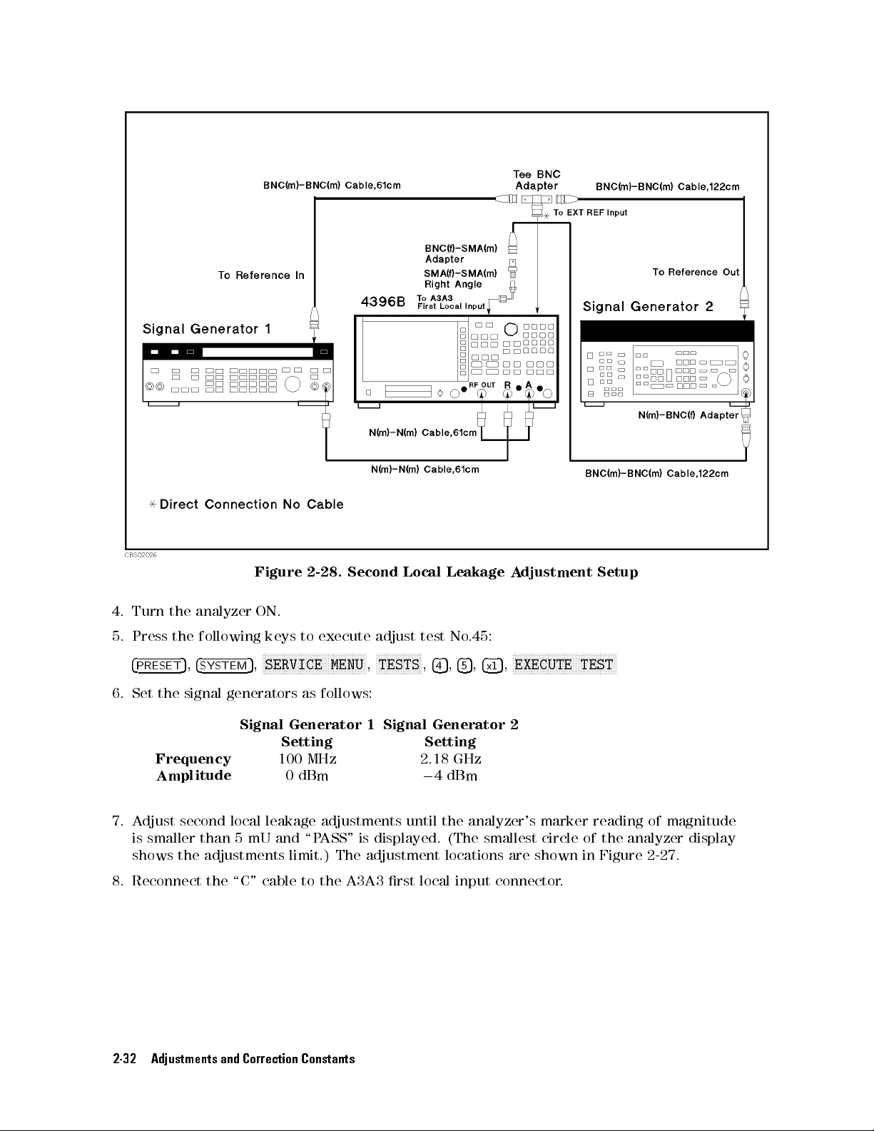
Figure
2-28.
Second
Local
Leakage
A
djustment
Setup
4. Turn
5.
6.
7. A
8. Reconnect the
the analyzer
Press
4
PRESET
Set
the
Frequency
Amplitude
the
following
5
,
4
SYSTEM
signal generators
ON.
keys
to
NN
NN
NN
NN
N
N
N
N
N
N
N
SERVICE MENU
5
,
Signal
Generator
Setting
100
0 dBm
execute
N
N
N
N
N
N
N
N
N
N
NN
NN
NN
NN
N
N
N
N
as follows:
MHz
adjust
NN
N
TESTS
,
1
NN
NN
NN
N
N
N
N
N
N
Signal
test
No
N
N
N
,
5
,
4
4
4
Generator
Setting
2.18
GHz
0
4 dBm
.45:
5
5
NN
NN
NN
NN
N
N
N
N
N
N
N
N
N
N
N
N
N
N
N
N
N
NN
NN
NN
NN
N
N
N
N
,
EXECUTE TEST
5
,
4
x1
N
2
djust second local leakage adjustments until the analyzer's marker reading of magnitude
is
smaller than 5 mU and \P
shows the
adjustments limit.) The adjustment locations are shown in Figure 2-27.
\C" cable to the A3A3 rst local input connector
ASS" is displayed. (The smallest circle of the analyzer display
.
2-32 Adjustments and Correction Constants
Page 65

RF OUT
The
purpose
signal
linearity
Level Correction
of
this
procedure is
and
atness
to obtain
.
Constants
the correction
constants that
correct the
RF OUT
Required
P
ower
Meter
P
ower
Sensor
Procedure
1.
Run
the
Constants
2.
3.
Choose
F
ollow
shows
the
the
the
Equipment
:
:
:
:
:
:
:
:
:
:
:
:
:
:
:
adjustment
using
the
RF
OUT
adjustment
equipment
:
:
:
:
:
:
::
:
:
:
::
::
::
program
A
djustments
Level
Correction
program
setup
::
::
:
:
:
:
:
:
:
:
:
and
display
Program
instructions
for
the
:
:
:
:
:
:
:
:
:
:
:
:
:
:
:
:
:
:
the
").
Constants
Correction
:
:
:
:
:
:
:
:
:
::
main
to
update
Constants
.
:
:
::
::
::
::
::
:
:
menu
:
:
:
:
:
:
:
:
:
(see
the
correction
.
:
:
:
:
:
:
:
:
:
:
:
:
:
\Updating
:
:
:
:
:
:
:
:
:
:
:
:
::
:
:
::
::
::
Correction
constants
::
:
:
::
:
:
:
:
:
:
:
.
Figure
:
:
:
:
:
:
:
436A
:
:
:
:
:
:
8482A
2-29
Figure 2-29. RF OUT Level Correction Constants Setup
Adjustments and Correction Constants 2-33
Page 66
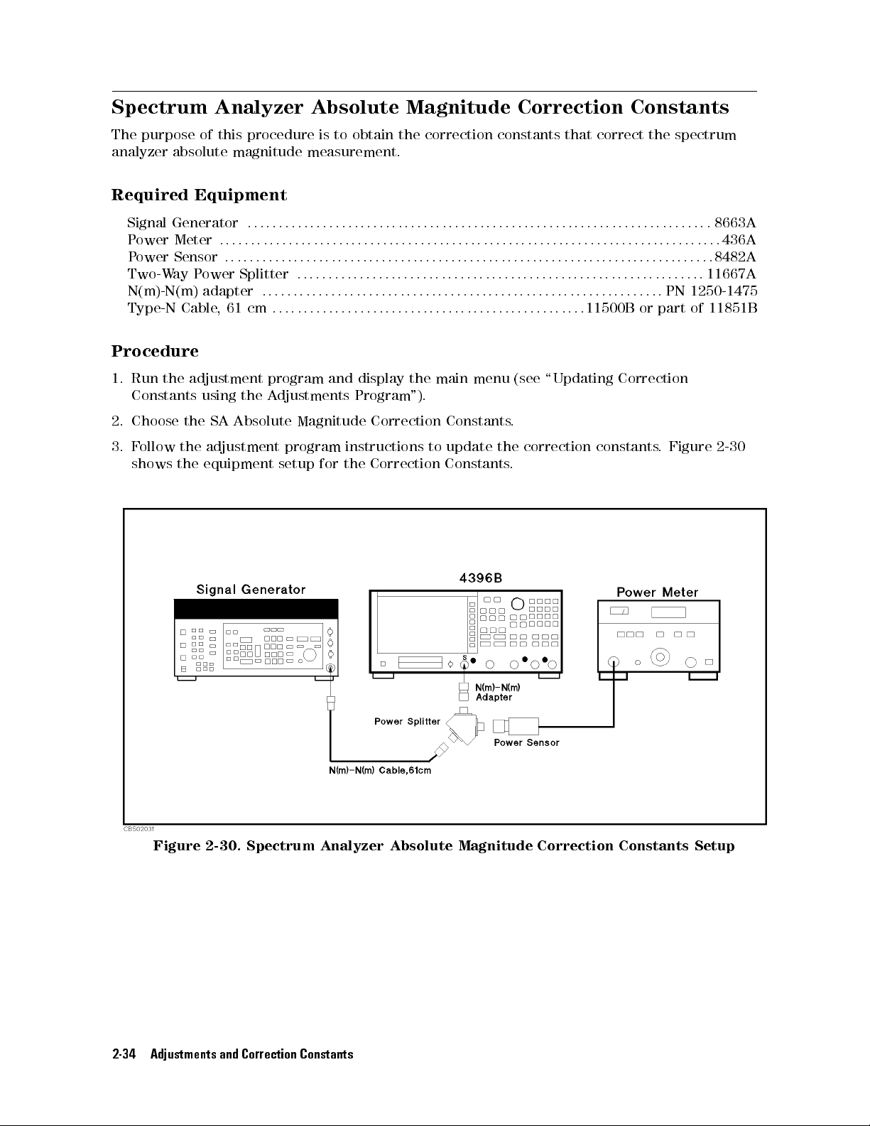
Spectrum Analyzer
The
purpose
analyzer
of
absolute
this
procedure is
magnitude
Absolute Magnitude
to obtain
measurement.
the correction
Correction Constants
constants that
correct the
spectrum
Required
Signal
P
P
Two-W
N(m)-N(m)
Type-N
Procedure
1.
2.
3.
Generator
ower
Meter
ower
Sensor
ay
Cable
Run
the
Constants
Choose
F
ollow the
shows
the
the
Equipment
:
:
:
:
:
:
:
:
:
:
:
:
:
:
:
:
:
:
::
::
:
:
:
:
:
:
:
:
:
:
::
P
ower
Splitter
adapter
,
adjustment
using
SA
adjustment program
equipment setup
:
61
cm
the
Adjustments
Absolute
:
:
:
:
:
:
:
:
:
program
:
:
:
:
:
:
:
::
::
:
:
:
:
:
:
::
::
:
:
:
:
:
:
:
:
:
:
:
:
:
::
:
:
:
:
:
::
::
:
:
:
:
::
::
::
and
Magnitude
instructions to
for the
::
::
:
:
:
:
:
:
:
:
:
:
:
:
:
:
:
:
:
:
:
:
:
:
:
:
:
:
:
:
::
::
::
:
:
:
:
:
:
:
:
:
:
:
:
:
:
::
::
::
::
:
:
:
:
:
:
:
:
:
:
:
:
:
:
::
::
:
:
:
:
:
:
:
:
:
:
:
:
:
:
::
:
:
:
:
:
:
:
:
:
:
:
:
:
:
:
:
display
Program
the
main
").
Correction
Correction Constants
Constants
update the
:
:
:
:
:
:
::
:
:
:
:
:
:
:
:
::
:
::
menu
:
:
::
::
::
:
:
:
:
:
:
:
:
:
::
::
::
::
::
::
(see
.
.
::
:
:
:
:
:
:
:
:
:
:
:
:
:
:
:
:
:
:
:
:
:
:
:
:
::
:
:
:
:
:
:
::
:
:
:
:
:
:
:
:
:
:
:
:
:
\Updating
correction
:
:
:
:
:
:
:
:
::
:
:
:
:
::
:
:
:
:
:
:
:
:
:
:
:
11500B
constants
:
:
:
:
:
:
:
:
::
::
:
:
:
::
::
:
:
:
:
:
:
:
:
:
:
:
:
:
:
:
:
:
::
or
Correction
::
::
:
:
:
:
:
:
::
:
PN
part
.
Figure
:
:
::
:
:
:
8663A
:
:
:
:
:
:
:
:
:
:
:
:
::
::
:
11667A
1250-1475
of
11851B
:
436A
8482A
2-30
Figure 2-30. Spectrum Analyzer
2-34 Adjustments and Correction Constants
Absolute Magnitude Correction Constants Setup
Page 67

Network Analyzer
The
purpose
analyzer
of
absolute
this
procedure is
magnitude
Absolute Magnitude
to obtain
measurement.
the correction
Correction Constants
constants that
correct the
network
Required
Signal
P
P
Two-W
N(m)-N(m)
Type-N
Procedure
1.
2.
3.
Generator
ower
Meter
ower
Sensor
ay
Cable
Run
the
Constants
Choose
F
ollow the
shows
the
the
Equipment
:
:
:
:
:
:
:
:
:
:
:
:
:
:
:
:
:
:
::
::
:
:
:
:
:
:
:
:
:
:
::
P
ower
Splitter
adapter
,
adjustment
using
NA
adjustment program
equipment setup
:
61
cm
the
Absolute
:
:
:
:
:
:
:
:
:
program
Adjustments
:
:
:
:
:
:
:
::
::
:
:
:
:
:
:
::
::
:
:
:
:
:
:
:
:
:
:
:
:
:
::
:
:
:
:
:
::
::
:
:
:
:
::
::
::
and
Magnitude
instructions to
for the
::
::
:
:
:
:
:
:
:
:
:
:
:
:
:
:
:
:
:
:
:
:
:
:
:
:
:
:
:
::
::
::
:
:
:
:
:
:
:
:
:
:
:
:
:
:
::
::
::
::
:
:
:
:
:
:
:
:
:
:
:
:
:
::
::
:
:
:
:
:
:
:
:
:
:
:
:
:
:
::
:
:
:
:
:
:
:
:
:
:
:
:
:
:
:
display
Program
the
main
").
Correction
Correction Constants
Constants
update the
:
:
:
:
:
::
:
:
:
:
:
:
:
:
:
:
::
menu
:
:
::
:
:
:
:
:
:
:
:
::
::
::
::
::
::
::
:
:
:
:
:
:
:
:
:
:
:
:
:
:
:
:
:
::
::
:
:
::
::
:
:
::
:
:
:
:
(see
\Updating
.
correction
.
:
:
:
:
:
:
:
:
:
:
:
:
:
:
:
:
:
:
:
:
:
:
:
:
:
:
:
:
:
:
:
:
:
:
:
11500B
:
:
:
:
:
:
:
:
:
:
:
:
:
::
::
::
:
:
:
::
::
::
:
:
:
:
:
:
:
:
:
:
:
:
:
:
:
:
:
or
Correction
constants
:
::
:
:
:
:
::
::
:
:
:
:
:
:
::
:
PN
part
.
Figure
:
:
::
:
:
:
8663A
:
:
:
:
:
:
:
:
:
:
:
:
8482A
::
::
:
11667A
1250-1475
of
11851B
:
436A
2-31
Figure 2-31. Network Analyzer
Absolute Magnitude Correction Constants Setup
Adjustments and Correction Constants 2-35
Page 68

Crystal Filter
The
purpose
frequency
of
this
response
Correction Constants
procedure is
to obtain
the correction
.
constants that
correct the
crystal lter
Required
Signal
Type-N
Generator
Cable
Procedure
1.
Run the
Constants
2.
Choose the
3.
F
ollow
the
shows
the
Equipment
:
:
:
,
61
cm
adjustment
using the
Crystal
Filter
adjustment
equipment
:
:
:
:
:
:
:
:
:
:
:
:
:
:
:
program
A
djustments
Correction
program
setup
::
::
::
:
::
::
::
and
instructions
for
the
:
:
:
:
:
:
:
:
:
:
:
:
:
:
:
display
Program
Constants
Correction
:
:
:
:
the
").
:
:
:
:
:
:
to
:
:
main
:
:
:
:
:
::
::
:
:
:
:
:
:
::
menu
.
update
Constants
::
the
::
::
.
:
:
:
(see
:
:
:
:
:
:
:
:
:
:
:
:
:
:
:
:
:
:
\Updating
correction
:
:
:
:
:
:
:
11500B
constants
:
:
::
::
::
:
:
or
part
Correction
.
Figure
:
:
:
:
:
of
11851B
8663A
2-32
Figure 2-32. Crystal Filter Correction Constants Setup
2-36 Adjustments and Correction Constants
Page 69

IF Gain
The
purpose
changing
Errors Correction
of
this
procedure is
errors
for
network
analysis
Constants
to obtain
and
the correction
constants that
spectrum analysis
correct the
IF gain
.
Required
Signal
Type-N
Generator
Cable
Procedure
1.
Run the
Constants
2.
Choose the
3.
F
ollow
the
and
Figure
Equipment
:
:
:
:
:
:
:
:
:
:
:
,
61
cm
:
:
:
:
:
:
:
adjustment program
using the
IF
adjustment
2-34
Gain
Errors
show the
A
djustments
Correction
program
equipment
:
:
:
:
::
::
::
:
::
::
::
:
:
and display
Program
instructions
:
:
:
:
:
:
:
:
:
:
:
:
:
the
").
Constants
setups
:
:
:
:
:
:
to
for
:
:
main
:
:
:
:
:
:
:
:
:
:
menu
.
update
the
:
:
:
:
::
::
::
:
::
::
::
:
:
(see
the
correction
Correction
:
:
:
:
:
:
:
:
:
:
:
:
:
\Updating
Constants
:
:
:
:
:
:
:
11500B
constants
:
:
:
:
:
:
:
:
or
Correction
.
::
::
part
.
Figure
::
of
:
:
:
8663A
11851B
2-33
Figure 2-33. IF Gain Errors Correction Constants Setup 1
Adjustments and Correction Constants 2-37
Page 70

Figure 2-34.
IF Gain
Errors Correction
Constants Setup
2
2-38 Adjustments and Correction Constants
Page 71

Network Analyzer
The
purpose
analyzer
of
this
magnitude
procedure is
ratio
and
Magnitude Ratio/Phase
to obtain
phase
measurement
the correction
for A/R
constants that
and B/R.
Correction Constants
correct the
network
Required
Two-W
ay
N(m)-N(m)
Type-N
Cable
Procedure
1.
Run the
Constants
2.
Choose the
3.
F
ollow
the adjustment
Figure
2-35
measurements
correct
the
Equipment
P
ower
Splitter
adapter
,
61
cm
:
:
:
:
(2
:
:
:
:
:
:
:
:
required)
adjustment program
using the
NA
Adjustments
Magnitude
Ratio/Phase
program
and
Figure
are
done
2-36
for
dierence between
:
:
:
:
:
:
:
:
:
:
:
::
::
::
:
:
:
and display
Program").
instructions
show
the
each
of
the power
::
::
::
:
:
:
:
:
:
:
:
:
:
:
:
::
::
the
Correction
equipment
A/R
and
:
:
:
:
:
:
:
:
:
:
:
:
:
:
:
:
:
:
:
:
:
:
:
::
::
:
:
:
:
:
:
:
:
:
:
main
menu
Constants
to
update
setups
B/R,
changing
splitter arms
:
:
:
::
:
:
the
.
:
::
:
:
(see
for
:
:
::
::
::
:
:
:
:
:
:
:
:
:
:
:
:
:
::
::
\Updating
.
correction
the
Correction
the power
:
:
:
:
:
:
:
:
:
:
:
:
:
:
:
:
:
:
:
:
:
:
:
:
:
:
::
:
11500B
or
Correction
constants
Constants
splitter connection,
:
:
:
PN
part
.
:
:
::
:
11667A
1250-1475
of
11851B
.
Two
to
Figure 2-35. Network Analyzer Magnitude Ratio/Phase Correction Constants Setup 1
Adjustments and Correction Constants 2-39
Page 72

Figure 2-36.
Network Analyzer
Magnitude Ratio/Phase
Correction Constants
Setup
2
2-40 Adjustments and Correction Constants
Page 73
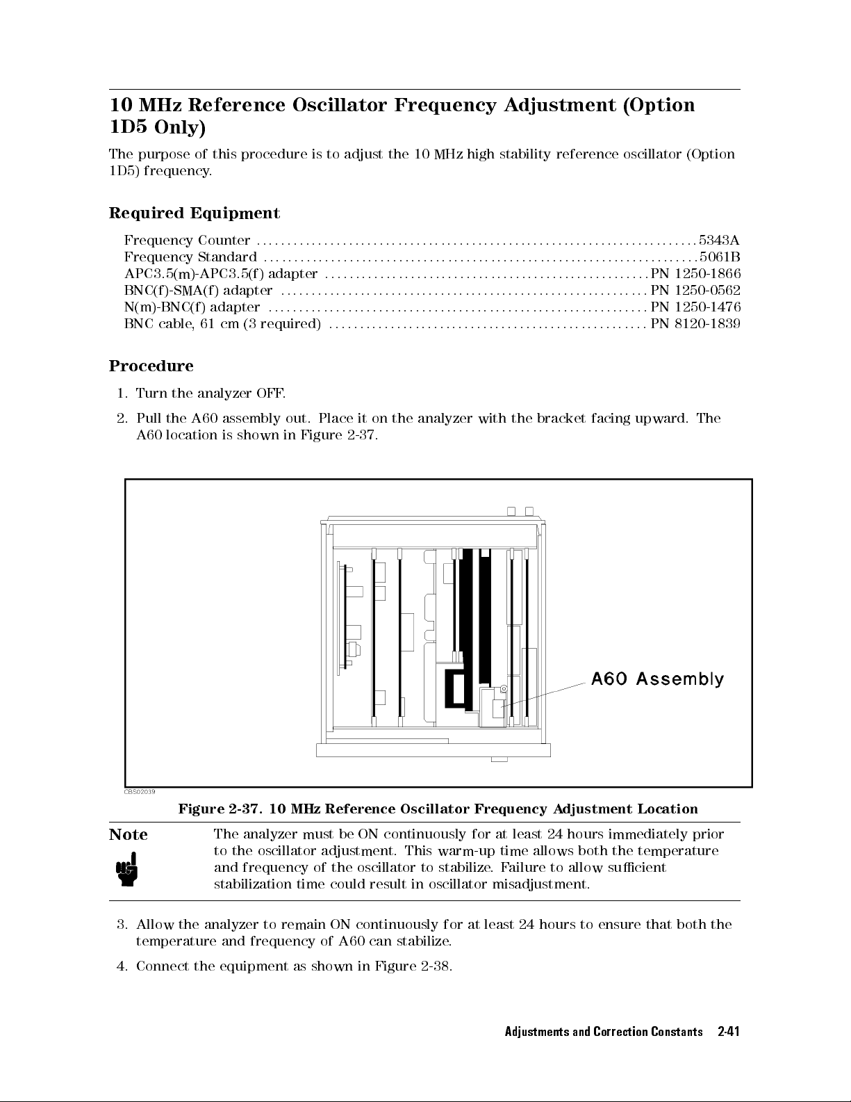
10 MHz
1D5
The
1D5)
Only)
purpose of
frequency.
Reference Oscillator
this procedure
is to
adjust the
Frequency A
10 MHz
high
stability
djustment (Option
reference
oscillator
(Option
Required
Frequency
Frequency
APC3.5(m)-APC3.5(f)
BNC(f)-SMA(f)
N(m)-BNC(f)
BNC
Procedure
1. Turn
2. Pull
A60 location
Equipment
Counter
cable
,
61
the
analyzer
the
A60
adapter
adapter
cm
assembly
is shown
:
:
:
:
:
:
adapter
:
:
(3
required)
OFF
:
:
:
:
:
:
:
:
:
:
:
:
::
.
out.
in
:
::
::
:
:
::
::
:
:
:
:
:
:
::
::
Place
Figure
:
::
::
::
:
::
:
::
:
:
:
:
:
::
:
:
::
2-37
:
:
:
::
:
:
:
:
:
:
:
:
:
:
:
:
:
:
:
:
:
::
::
::
:
:
:
:
:
:
:
:
:
:
:
:
:
:
:
:
:
:
:
::
::
::
:
:
:
:
:
:
:
:
5343A
:
:
:
:
:
:
:
:
:
:
:
:
:
:
:
:
:
::
::
::
:
:
:
:
:
:
:
:
:
:
:
:
:
:
:
:
:
:
:
::
::
::
:
:
:
:
:
:
:
5061B
:
:
::
::
::
:
:
:
:
:
:
:
:
:
:
:
:
:
:
:
:
:
:
:
::
::
::
:
:
:
:
:
:
:
:
:
:
:
:
:
:
PN
1250-1866
::
:
:
:
:
:
:
:
:
:
:
:
:
:
:
:
:
:
::
::
::
::
:
:
:
:
:
:
:
:
:
:
:
:
:
:
:
:
:
::
PN 1250-0562
:
:
:
:
:
:
:
:
:
:
:
:
:
:
::
::
::
::
:
:
:
:
:
:
:
:
:
:
:
:
:
:
:
:
:
::
::
::
::
PN
1250-1476
::
:
:
:
:
:
:
:
:
:
:
:
:
:
:
:
:
:
::
::
::
::
:
:
:
:
:
:
:
:
:
:
:
:
:
:
:
:
:
::
:
PN
8120-1839
it
on
the
analyzer
.
with
the
bracket
facing
upward.
The
Figure 2-37. 10 MHz Reference Oscillator Frequency A
Note
3. Allow the analyzer to remain ON continuously for at least 24 hours to ensure that both the
temperature and frequency of A60 can stabilize.
4. Connect the equipment as shown in Figure 2-38.
The analyzer must be ON continuously for at least 24 hours immediately prior
to the oscillator adjustment. This warm-up time allows both the temperature
and frequency of the oscillator to stabilize
stabilization time could result in oscillator misadjustment.
.F
ailure
Adjustments and Correction Constants 2-41
djustment Location
to allow sucient
Page 74
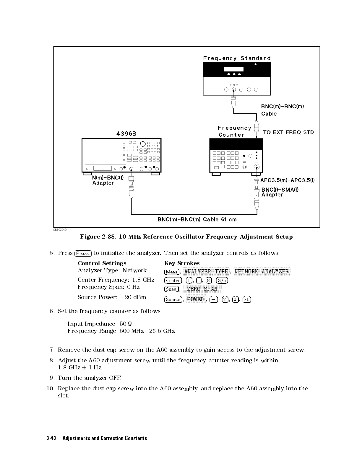
Figure
2-38.
10
MHz
Reference
Oscillator
Frequency
A
djustment
Setup
5. Press
6.
Set
the
5
Preset
to
4
Control
Analyzer
Center
Frequency
Source
frequency
initialize the
Settings
Type:
Network
Frequency:
Span:
P
ower:
0
counter
analyzer
1.8
0
Hz
20 dBm
as
follows:
GHz
.
Then
K
4
4
4
4
ey
Meas
Center
Span
Source
set
the
analyzer
Strokes
N
N
NN
NN
N
N
N
N
N
N
N
N
N
N
N
N
N
N
N
N
ANALYZER TYPE
5
,
5
5
,
4
1
N
N
N
N
N
N
N
ZERO
5
,
N
N
N
N
POWER
5
,
N
5
,
,
4
4
.
8
N
N
N
N
N
N
N
N
N
N
N
N
N
N
NN
NN
SPAN
N
N
N
N
N
N
N
N
NN
NN
N
,
N
N
5
4
N
N
,
NN
0
NN
NN
4
G/n
N
N
N
N
N
5
controls
N
N
N
N
N
N
N
N
5
N
N
N
5
,
4
2
N
N
,
,
4
as
N
N
NN
NN
N
N
N
N
N
N
N
N
N
N
NETWORK ANALYZER
5
5
,
4
x1
0
follows:
N
N
N
N
N
N
N
N
N
N
N
NN
NN
N
N
N
N
N
N
N
N
N
N
N
N
N
N
N
N
N
N
N
Input Impedance 50
Frequency Range 500 MHz - 26.5 GHz
7. Remove the dust cap screw on the A60 assembly to gain
8. A
djust the A60 adjustment screw until the frequency counter reading is
1.8 GHz
6
1Hz
.
access to the adjustment screw
within
9. Turn the analyzer OFF.
10. Replace the dust cap screw into the A60 assembly, and replace the A60 assembly into the
slot.
.
2-42 Adjustments and Correction Constants
Page 75

Troubleshooting
INTRODUCTION
This
chapter describes
determine
whether the
troubleshooting
of this
overall troubleshooting
analyzer is
manual.
faulty,
summary and
or not.
The
provides
procedure
the
is
performed
procedure
rst
in
3
to
the
TROUBLESHOOTING
The
troubleshooting
approach.
of
accessories
splitters
keyboards
This
This
refers
digital
the
Theory
Isolate
of
two
the
faulty
This
,
cables
,
chapter
chapter
the
technician
control,
F
aulty
functional
group
for
also
identies
of
Operation
Troubleshooting
procedures
Figure 3-1
Each of
time,
employ
.
diagrams the
the ve
the assemblies
more
lengthy
Post-Repair Procedures
Post-Repair Procedures
strategy
chapter's
or
system
,
and
instance
rst
peripherals
calibration
,
and
suggests
one
to
the
source
,
receiver
chapter
Group
Troubleshooting
groups:
and
refers
and
Isolate
troubleshooting
chapters following
within a
,
complicated
, is the last chapter of the troubleshooting portion of the manual.
is organized by assembly and notes what adjustment to perform and
SUMMARY
of
this
step
kits
which
remedies
or
some
appropriate
,
and
.
source
,
receiver.
the
technician to
F
aulty Group
group until
procedures
manual
is
to
verify
.
A
ccessories
.
P
eripherals
typically
for
system
faulty
groups
chapter
accessories
,
the next
organization.
Isolate
the faulty
is
based
use
on
the
operation
are
devices
are
devices
an
GPIB
problems
in
the
.
The
ve
.
Descriptions
a
external
analyzer's
chapter,
Isolate F
aulty
the appropriate
Troubleshooting
F
aulty
Group
Troubleshooting
assembly
.
verication
of
the
like
test
like
computers
connection
to
ve
functional
of
these
assumes
Group
that
Troubleshooting
chapter
,
stress simple
is
identied.
(rather
analyzer
sets
and
the
than
alone
,
power
,
printers
a
line
analyzer
functional groups
groups
.
groups
the
fault
These
are
are provided
rst
, straight
veries
These
symptomatic)
,
independent
probes
connection.
.
power supply
is
within
identies
chapters
forward
,
one
ve
how to verify proper instrument operation following the replacement of an assembly
, power
,
and
.
Then
one
,
at
a
chapters
.
,
in
Troubleshooting 3-1
Page 76
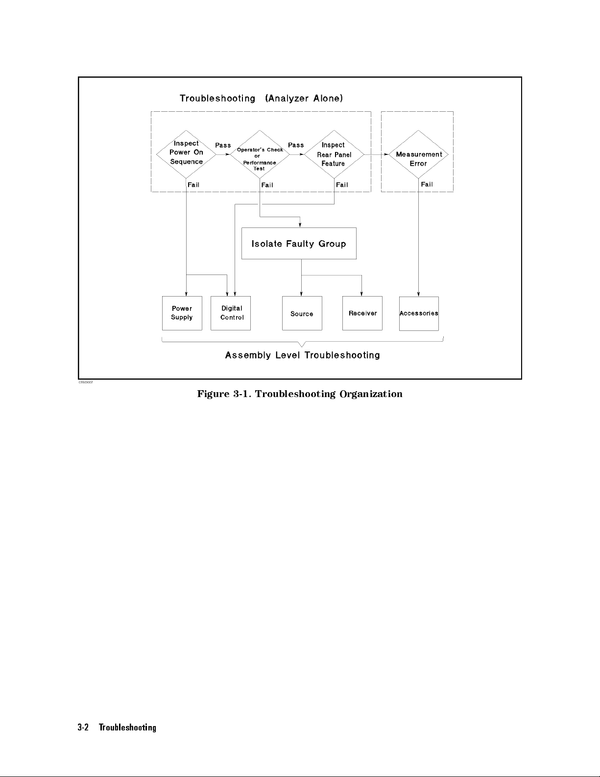
Figure
3-1.
Troubleshooting
Organization
3-2 Troubleshooting
Page 77
START
A
system
analyzer
perform
1.
Disconnect
power
2.
P
erform
3.
P
erform
4.
P
erform
If
the
HERE
failure
(in
a
the
,
and
the
the
the
analyzer has
measurements
interconnect
problems
.
can
be caused
peripheral
following
everything
RF
cables.
INSPECT
OPERA
INSPECT
or
programming).
procedure
from
THE
TOR's
THE
passed all
or
unexpected operations
cables
, calibration
by a
problem in
.
the
analyzer:
POWER
CHECK
REAR P
of the
ON SEQUENCE
in
this chapter
ANEL FEA
checks in
, suspect
and verication
the analyzer
To
verify the
All
test
TURE
steps
the accessories
kit devices
and its
operation of
set interconnect,
in this
chapter
.
in
this chapter
2
through
4
but
.A
,test
set
accessories or
the analyzer
GPIB cable
.
.
it
still
making
ccessories
can
all
such
induce
out of
alone,
,probe
incorrect
as
RF
system
the
or
Congure the
A
ccessories
Troubleshooting
system as
it
is
normally
chapter
.
used
and
reconrm
the
problem.
Continue
with
the
Troubleshooting 3-3
Page 78

INSPECT THE
POWER
ON SEQUENCE
Check
Turn
If
on
R
equirements
If
Check
Turn
1.
2.
The
case
the
the
Beep
The
the
problem
on the
the
analyzer
fan
of
rear
the Front
is
4
Ch
seconds
3.
The
analyzer displays
If case
Check
Turn
If
with
one
of
the
of
the
Error
analyzer
the
Digital
F
an
power
should
be
unexpected
panel).
Check the
in
Appendix
persists
analyzer
sounding.
5
LED
1
turns
.
unexpected
Message
power
error
message
Control
on. Inspect
rotating
results
and
,
check
line voltage
C.
, continue
P
anel
and
watch
on
LEDs
and
the graticule
results
,
continue
on.
Inspect the
or a
Troubleshooting
audible.
A
with the
for
the
the
analyzer
status
the fan
Cline
setting. F
Power
and
Displays
following
.
with
LCD
annotation
chapter
on the
power to
rear panel.
the analyzer
or
setting
Supply Troubleshooting
events
displays
Digital
.
No
error
listed
in
Internal
Control
message
below
this
T
Troubleshooting
.
.
Check
the
line
order:
est
In
should
appears
the
voltage
chapter
Progress
be
displayed.
on
the
fuse
,
see
the
.
for
several
chapter
LCD
,
(rating
P
ower
.
continue
listed
POWER
Svc
These
appears
If
the
the
Digital
ON
TEST
FAILED
(Status annotation)
error messages
, refer
response
to the
of
Control
indicate
Error
front
Troubleshooting
Messages
panel,
that
GPIB
one
of
power-on
in
Messages
commands
chapter
self
tests
fails
.
If
an
other
error
message
.
,
or
built-in
FDD
is
unexpected,
continue
with
.
3-4 Troubleshooting
Page 79
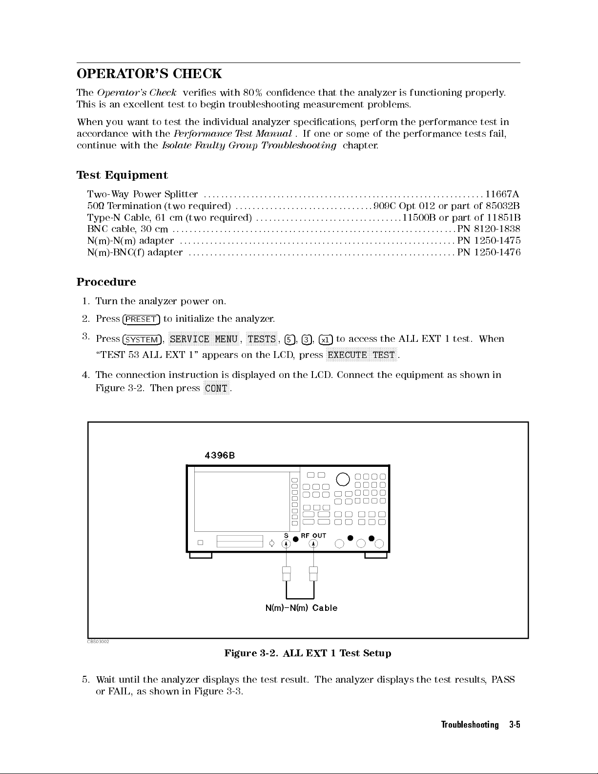
OPERATOR'S
The
Operator's
This
is
an
When
you
accordance
continue
T
est Equipment
with
Check
excellent
want
to
with
the
the
CHECK
veries
test
to
test
the
P
erformance
Isolate
with 80%
begin troubleshooting
individual analyzer
T
Faulty
Group Troubleshooting
condence that
est
Manual
the analyzer
measurement problems
specications,
.If
one or
perform the
some of
chapter.
is functioning
.
performance test
the performance
properly.
tests
fail,
in
Two-W
50
Type-N
BNC
N(m)-N(m)
N(m)-BNC(f)
Procedure
1.
2.
3.
4.
ay
T
ermination
Cable
cable
Turn
the
Press
4
PRESET
Press
4
SYSTEM
\TEST
The connection
Figure 3-2
53
P
ower
,
61
,
30
cm
adapter
adapter
analyzer
5
ALL
.
Then
Splitter
(two
required)
cm
(two
:
:
:
:
::
:
:
:
:
power
to
initialize the
N
N
N
N
N
N
N
N
N
N
N
N
SERVICE
5
,
EXT
1"
instruction
press
:
::
::
:
:
:
:
:
:
:
:
N
N
N
N
N
N
N
N
N
appears
N
N
CONT
:
:
:
:
:
:
:
::
:
required)
::
:
:
:
:
::
::
::
::
:
:
::
::
::
on.
analyzer.
NN
NN
N
N
N
N
N
N
N
N
N
N
N
N
N
MENU
is
displayed
N
N
NN
N
N
N
N
N
N
N
N
.
::
:
:
:
:
:
:
:
:
::
N
N
N
TESTS
,
on
:
:
:
:
N
N
::
:
:
:
:
:
:
:
:
:
N
N
N
N
the
:
:
N
:
:
:
:
:
N
N
:
:
::
:
:
:
:
:
N
N
N
N
LCD
:
:
:
N
:
::
:
:
:
,
on
:
:
:
:
:
:
:
:
:
:
:
:
:
:
:
::
::
::
:
:
:
:
:
:
:
:
:
:
:
:
:
:
:
:
:
:
:
::
::
::
:
11667A
::
::
:
:
:
:
:
:
:
:
:
:
:
:
:
:
:
:
909C
Opt 012
::
::
::
::
:
:
:
:
:
:
:
:
:
:
:
:
:
:
:
:
:
::
:
11500B
:
:
:
:
::
::
::
::
:
:
:
:
:
:
:
:
:
:
:
:
:
:
:
:
:
::
:
:
:
:
:
:
:
:
::
::
::
::
:
:
:
:
:
:
:
:
:
:
:
:
:
:
:
:
:
:
:
:
:
:
:
:
::
::
::
::
:
:
:
:
:
:
:
:
:
:
:
:
5
5
4
3
,
4
x1
LCD
5
to
access
N
N
N
N
N
N
N
N
N
N
N
N
N
N
N
NN
EXECUTE
.
Connect
NN
N
N
N
N
N
N
N
N
TEST
N
N
the
the
ALL
N
N
N
N
N
N
N
N
N
.
equipment
4
5
,
,
press
the
::
:
:
::
:
:
:
:
EXT
::
:
::
::
:
::
or part
or part
:
:
:
:
PN
::
:
PN
::
:
PN
1
test.
as
shown
of 85032B
of 11851B
8120-1838
1250-1475
1250-1476
When
in
Figure 3-2. ALL EXT 1 Test Setup
5. Wait until the analyzer displays the test result. The analyzer displays the test results,PASS
or FAIL, as shown in Figure 3-3 .
Troubleshooting 3-5
Page 80

If the
ALL EXT
1 test
fails
,
continue
with
step
18.
6.
7.
Press
At
5
4
to
access
*
the prompt,
Figure
the
connect
ALL
the
3-3.
Displayed
EXT
2
test.
equipment
Then
as
Result
press
shown
of ALL
N
N
N
N
EXECUTE
in
Figure
EXT T
N
N
N
N
N
N
N
N
N
N
NN
NN
N
N
N
N
N
N
3-4
N
N
N
N
N
N
N
TEST
.
Then
est
N
N
N
N
N
N
N
to
execute
press
N
NN
NN
NN
N
CONT
the
N
N
N
test.
N
N
N
.
Figure 3-4. ALL EXT 2 T
8. W
ait until
If the ALL EXT 2 test fails
9.
Press
10.
At the prompt, connect the equipment as shown in Figure 3-5. Then press
the analyzer displays P
ASS or F
AIL.
, continue with step 18.
4*5
to access the ALL EXT 3 test. Then press
est Setup
N
NNNNNNNNNNNNNNNNNNNNNNNNN
NNNNNNNNNNNN
EXECUTE TEST
3-6 Troubleshooting
to execute the test.
NNNNNNNNNNNNNN
CONT
.
Page 81
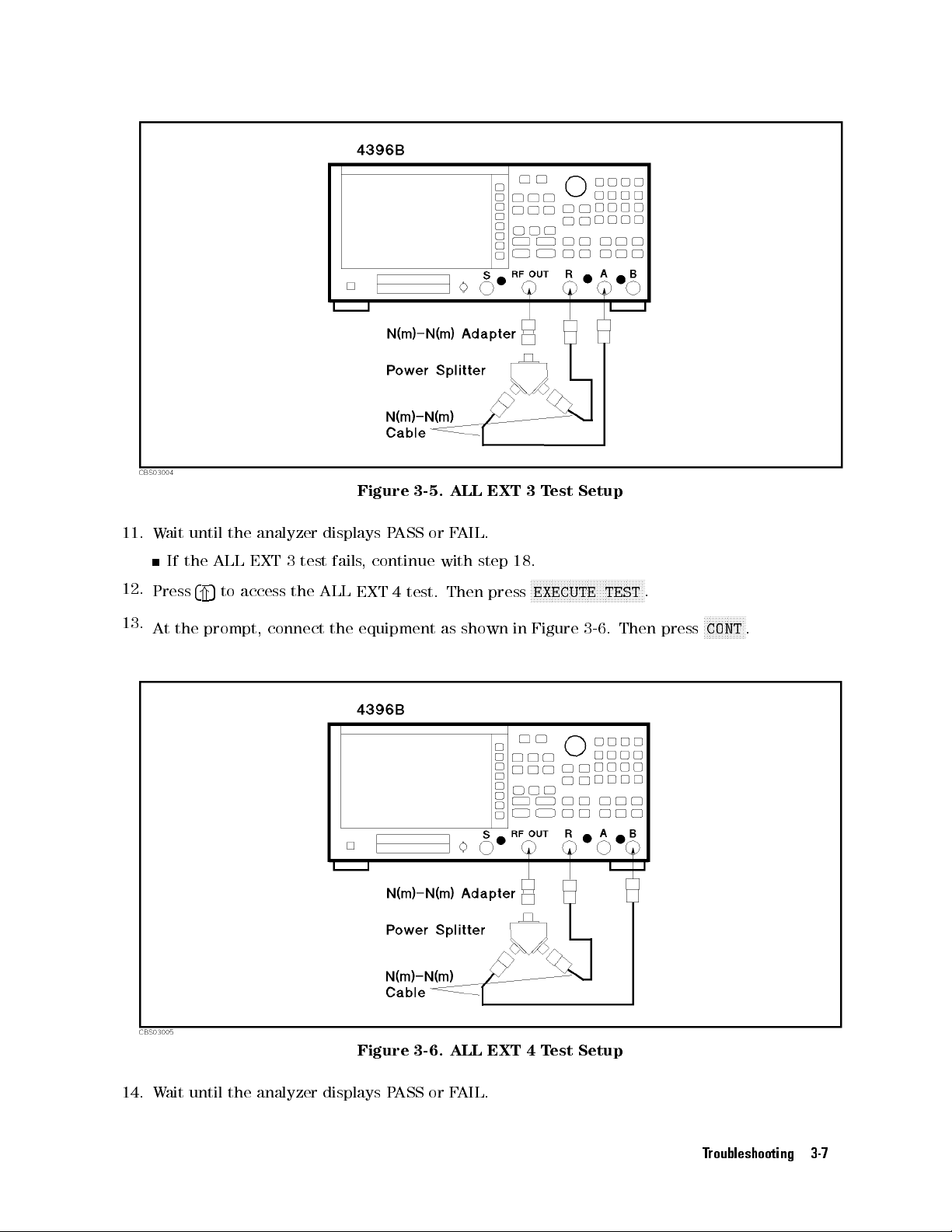
11.
12.
13.
W
ait
If the
Press
At the
until
ALL
5
4
to
*
prompt,
the
access
analyzer
EXT
3
the
connect
displays P
test
fails
ALL
the
Figure 3-5.
ASS or
,
continue
EXT
4
test.
equipment
ALL EXT
F
AIL.
with
step
Then
press
as
shown
3T
18.
N
N
N
N
N
EXECUTE
in
Figure
est Setup
N
N
N
N
N
N
N
N
N
N
N
N
N
NN
N
N
N
N
3-6
N
N
N
N
N
N
N
N
TEST
.
Then
N
N
N
N
N
N
.
N
N
N
NN
N
N
N
N
N
N
N
N
N
CONT
press
.
Figure 3-6. ALL EXT 4 Test Setup
14. Wait until the analyzer displays PASS or FAIL.
Troubleshooting 3-7
Page 82
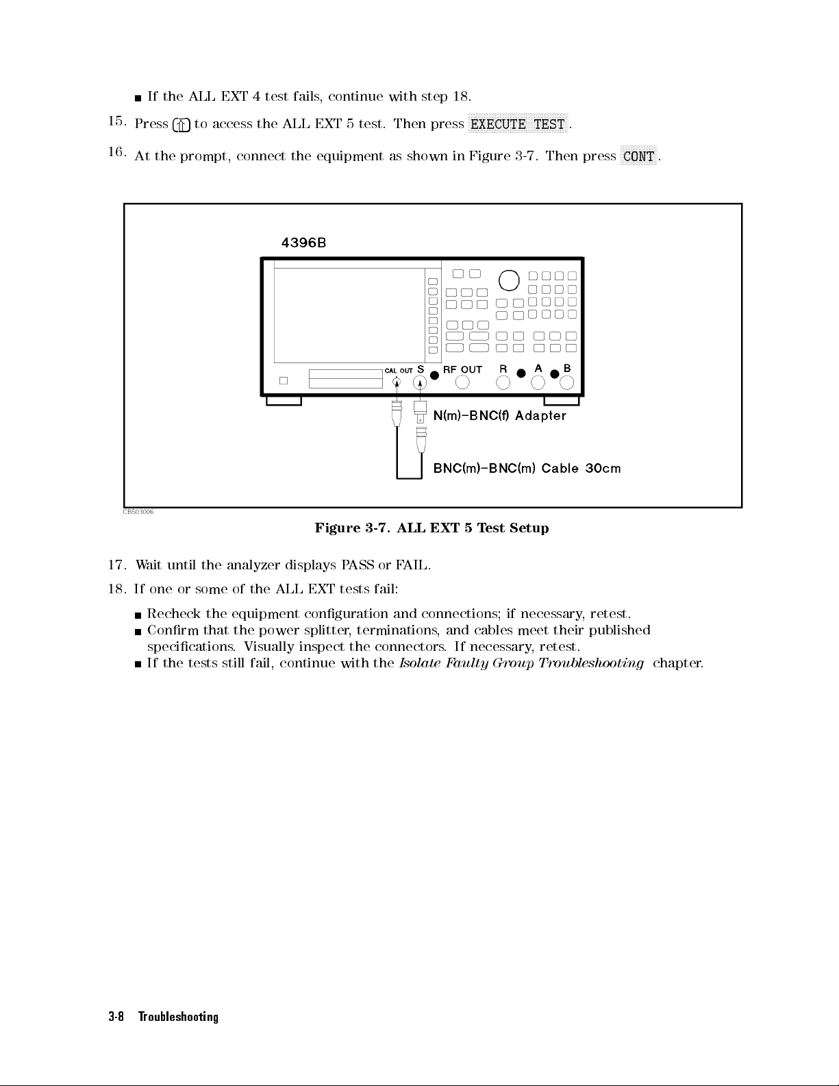
15.
16.
If the
Press
4
*
At
the prompt,
ALL EXT
5
to
access
4 test
fails,
the ALL
connect the
continue with
EXT 5
test. Then
equipment as
step
18.
press
shown in
N
N
N
N
N
N
NN
NN
NN
NN
NN
NN
EXECUTE
Figure
NN
N
3-7
N
N
N
N
N
TEST
N
N
N
N
.
N
NN
NN
NN
N
Then
.
press
N
NN
NN
NN
NN
CONT
NN
N
N
N
.
17.
18.
W
If
ait
until
the
one
or
some
Recheck
Conrm
the
that
specications
If
the
tests
analyzer
of
the
equipment
the
power
.
Visually
still
fail,
Figure
displays
ALL
EXT
conguration
splitter
inspect
continue
3-7.
P
ASS
or
tests
fail:
,
terminations
the
connectors
with the
ALL
EXT
F
AIL.
and
connections;
Isolate F
5
T
est
,
and
cables
.
If
necessary
aulty Group
Setup
if
necessary
meet
their
,
retest.
Troubleshooting
,
retest.
published
chapter
.
3-8 Troubleshooting
Page 83

INSPECT THE
If
the
Control
analyzer
Troubleshooting
is
operating unexpectedly
REAR P
chapter
ANEL FEA
after these
.
TURE
checks are
veried, continue
with
Digital
Check
If
perform
the GPIB
the unexpected
the following
Compatibility
B
ASIC
system.
GPIB
interface
and
the
B
I/O
and
GPIB
Select
GPIB
code
cables
Programming
Check
See
4396B
Check
See
Guide
the
the
Printing
User's
the
the
Connecting
and
Using
ASIC
,
see
,
P
arallel
Guide
mini
operations
, must
hardware
system.
binaries
the
see
the
syntax,
Out
,
DIN
a
HP
Interface
appear
checks
be
manuals
manuals
HP
9000
must
loaded,
see
the
to
verify
series
be
see
of
the
of
the
manuals
Interface
The
Measurement Result
and
make
a
hardcopy of
K
eyboard
Keyboard
Instrument
at
B
the
ASIC
when
controlling
the
problem
200/300,
installed
the
manuals
B
ASIC
system.
B
ASIC
of
the
Connector
Chapter
with
the
the
is
not
see
the
in
the
controller
of
the
B
system.
B
ASIC
system.
at the
Chapter 3,
the display
1, Installation
4396B.
analyzer
with
manuals
,
ASIC
.
and
with
an
external
the
see
controller
of
the
the
manuals
.
controller
system.
Network Analyzer
Setup
guide
of
of
controller
and
the
T
our
4396B
the
controller
of
the
User's
,
Troubleshooting 3-9
Page 84

Page 85

4
Isolate
Faulty
INTRODUCTION
Use
these procedures
two
procedures:
OPERA
TOR'S CHECK
PERFORMANCE
These
and
Use
are procedures
receiver.
the
Descriptions
OPERA
Troubleshooting
when
any
of
the
group
.
TOR'S
after you
TEST F
to determine
CHECK
chapter
performance
Group Troubleshooting
have read
FAILURE
TROUBLESHOOTING
AILURE TROUBLESHOO
which group
of
these
groups
FAILURE
fails
.
Use
the
tests
fail.
the
Troubleshooting
TING
is faulty
are
provided
TROUBLESHOO
PERFORMANCE
These
procedures
in
the
in
the
TING
TEST
isolates
Theory
when
F
chapter
two
functional
the
AILURE
the
.
This
chapter
groups:
of
Operation
Operator's
TROUBLESHOO
most
probable
provides
source
chapter
Check
TING
faulty
,
.
in
Isolate Faulty Group Troubleshooting 4-1
Page 86

OPERATOR'S
P
erform
chapter
the
fails
following
.
CHECK F
AILURE TROUBLESHOOTING
procedures sequentially
when the
Operator's Check
in
Troubleshooting
Check
This
uses a
when
it tuned
to
verify
A5
synthesizer
1.
P
erform
Manual
If
the
measurement
set
the
accuracy
If
this
test
the
next
Check
This
uses
signal.
2nd
LO
,
probably
1.
P
erform
P
erformance
2.
P
erform
Manual.
RF OUT
frequency
to
the
A5
the
(pn
analyzer
meets
fails
Check
RF
OUT
a
power
This
veries
and
A3A3
working.
the
the
Frequency
counter
1
GHz
or
synthesizer
is
probably
FREQUENCY
04396-90120).
problem
to
the
controls
the
specication.
,
continue
RF
OUT
meter
source
SOURCE
T
est
PO
WER
with
P
ower
P
ower
and
the
operation
.
LEVEL A
Manual
SWEEP LINEARITY
to
measure
a
particular
operation.
working.
A
CCURA
troubleshooted
of
the
the
Source
Level
section.
Level
a
power
of
the
If
the
level
CCURA
(pn
04396-90120).
the
actual
frequency
If
the
frequency
CY
TEST
in
appears
measurement
Troubleshooting
sensor
to
A3
source
accuracy
CY/FLA
measure the
meets
TNESS
TEST
frequency
of
the
measurement
accuracy
accordance
at
a
particular
problem.
module
its specication,
TEST
in
accordance
of
the
meets
with
the
frequency
Then
verify
chapter
.
If
actual power
that consists
in
accordance
with
analyzer
problem.
its
specication,
P
erformance
the
this
test
level
of A3A1
the
A3
the
P
erformance
RF
OUT
This
or
other
frequency
passes
of
the
ALC,
source
with
the
signal
purposes
the
T
est
controls
,
go
to
RF
OUT
A3A2
module
T
est
,
is
If
the
measurement
controls,
set the
Then verify
If this
If this
receiver.
test fails
test passes
Continue
the RF
problem
analyzer
OUT
,
continue
but still
with
troubleshooted
to
the
power
with
the
making
the
R
eceiver
4-2 Isolate Faulty Group Troubleshooting
particular
level
meets
Source
the
operator's
Troubleshooting
appears
controls
the
at a
.
And
specication.
Troubleshooting
check
failure
chapter
particular power
measure
chapter
,
the
the
RF
.
probable
.
level
OUT
or
power
faulty
other
level.
group
is
Page 87
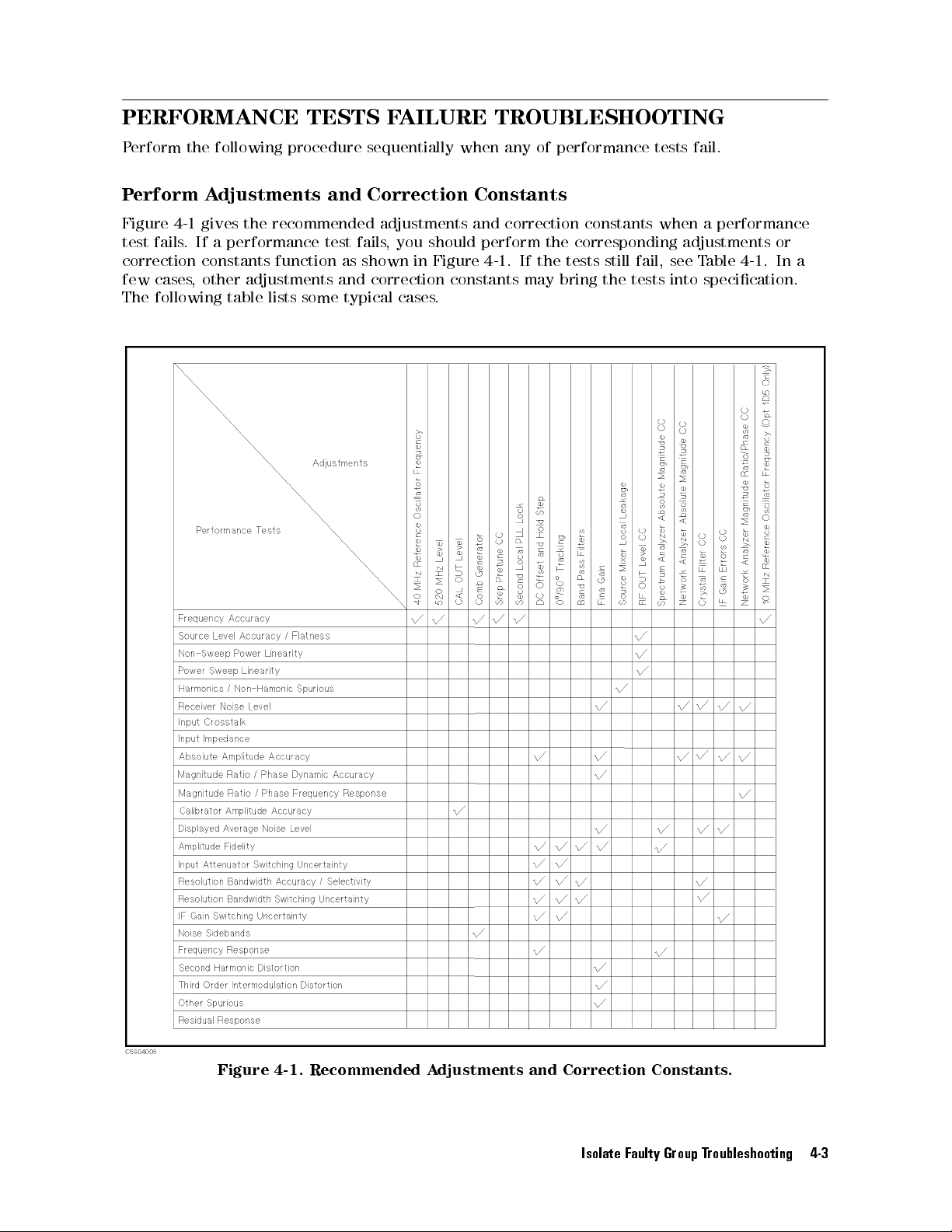
PERFORMANCE TESTS
P
erform
P
erform A
the
following
djustments and
procedure sequentially
Correction
FAILURE
when any
Constants
TROUBLESHOOTING
of performance
tests fail.
Figure
test
4-1 gives
fails.
correction
few
cases,
The
following
the
recommended
If
a
performance
constants function
other
adjustments
table
lists
some
test
and
fails
as
shown
correction
typical
adjustments
,
you
should
in
Figure
constants
cases
.
and
correction
perform
4-1
.
If
may
constants
the
corresponding
the
tests
bring
still
the
fail,
tests
when
a
adjustments
see
T
able
into
specication.
performance
or
4-1
.
In
a
Figure 4-1. Recommended Adjustments and Correction Constants.
Isolate Faulty Group Troubleshooting 4-3
Page 88
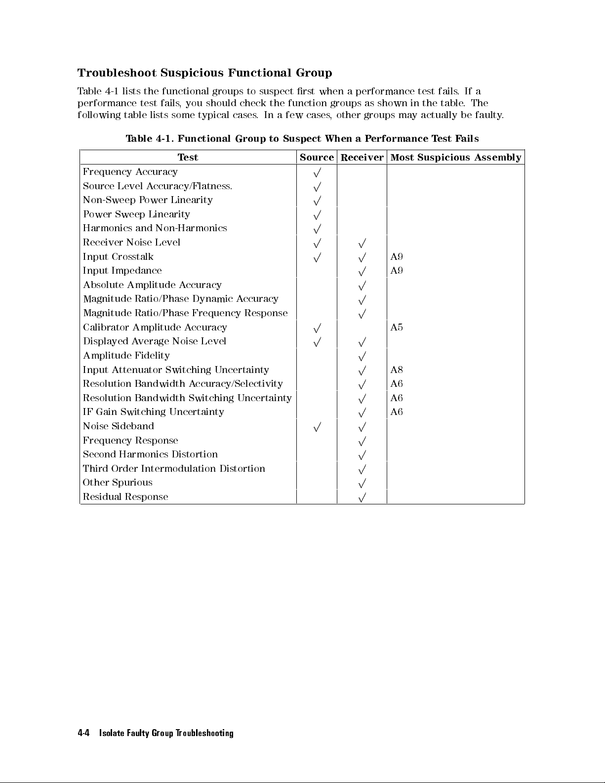
Troubleshoot
T
able
4-1
lists
the
performance
following
table
T
able
test
Suspicious
functional
fails
,
you
lists
some
4-1.
Functional
groups
should
typical
Functional
to
suspect
check
cases
Group
.
the
In
to
a few
Suspect
Group
rst
when a
function groups
cases,
other groups
When
performance test
as shown
in the
may actually
a
P
erformance T
fails.
table.
est F
If a
The
be faulty
ails
.
Frequency
Source
Accuracy
Level
Non-Sweep P
P
ower
Sweep
Harmonics
Receiver
Input
Input
Absolute
Magnitude
Magnitude
Calibrator
Displayed
Amplitude
Input
Resolution
Resolution
IF
Gain
Noise
Frequency
Second
Third
Other
Residual
and Non-Harmonics
Noise
Crosstalk
Impedance
Amplitude
Ratio/Phase
Ratio/Phase
Amplitude
A
Fidelity
Attenuator
Bandwidth
Bandwidth
Switching
Sideband
Response
Harmonics
Order
Spurious
Response
T
est
A
ccuracy/Flatness
ower Linearity
Linearity
Level
A
ccuracy
Dynamic
Frequency
A
ccuracy
verage
Noise
Level
Switching
A
ccuracy/Selectivity
Switching Uncertainty
Uncertainty
Distortion
Intermodulation
.
A
ccuracy
Response
Uncertainty
Distortion
Source Receiver Most
p
p
p
p
p
p p
p p
p
p
A9
A9
p
p
p
p p
A5
p
p
p
p
p
p p
A8
A6
A6
A6
p
p
p
p
p
Suspicious
Assembly
4-4 Isolate Faulty Group Troubleshooting
Page 89

P
ower Supply
INTRODUCTION
Use
this procedure
the
power supply
power
The
All
is
form.
Figure
If
chapter
supply functional
power supply
A40
Pre-Regulator
A50
DC-DC Converter
A2
P
ost-Regulator
assemblies
supplied
F
or
5-12
an
assembly
in
replacing
to
more
,
this
any
Figure
only if
.The
functional group
,
however
each
assembly
information
5-13
is
replaced,
manual.
assembly
Troubleshooting
you have
procedure is
group in
read
Troubleshooting
designed to
the shortest
possible time
consists of:
,
are
,
It
and
see
tells
related
.
Figure
about
Figure
T
able
what
to
the
5-1
shows
the
signal
5-14 at
13-1
additional
power
paths
the end
P
ost R
all
.
let
supply
power
epair
tests
,
and
you
identify
.
functional
lines
in
and
specic
of
this
chapter
Procedures
or
adjustments need
you
believe
the
bad
group
simplied
connector
.
in
the
the
problem
assembly
because
block diagram
pin
numbers
P
ost
R
epair
to
be
done
is
within
the
power
,see
Procedures
after
5
in
Power Supply Troubleshooting 5-1
Page 90

Figure 5-1. Power Supply Lines Simplied Block Diagram
5-2 Power Supply Troubleshooting
Page 91

START
1.
Check
Turn
the
follow
continue
the
HERE
Error
analyzer
instruction
with
the
Messages
power
next
of
the
Check
on. If
one of
displayed
the
Fan
error messages
error message
is R
otating.
listed below
.If
no error
appears on
message is
the display
displayed,
,
Error
These
indicate
protect
information
Note
Messages
POWER
POWER FAILED
FAILED
messages
the
them
ON
-
ON PostRegHot
are
associated
A2
protective
from
over
about
the
These
of
these
power
supplies
displays
operation,
analyzer
--
shutdown
current,
A2
shutdown
messages
message
on
sequence
,
+15
an
error
any
is
turning
Instruction
One or
+5
V
displayed
on
the
EIGHT
This indicates
+5
V
on
A2
minutes
still
with
the
circuit
over
voltage
circuit,
are
displayed
is
displayed,
,
the
V
,
+5
V
,
message
front
key
the
some of
,
-5
V,
-15 V
power
A2
post-regulator
LEDs
in
,-5
V,
-15
post-regulator
.
Then
displayed,
power
analyzer
-5
analyzer
supplies
is
shutting
,
under
see
the
only
the
V
,
-15 V
and
stops
operations
power
A2
power
are displayed
supplies
this
START
A2 power
V
,
are
shut
.
Cool
turn
the
replace
functional
down
voltage
Figure
after
analyzer's
checks
.
If
a
power
its
operation.
are
disabled.
o.
supplies
are
shut down
. Continue
HERE.
supplies
down
down
analyzer
A2
post-regulator
some
,
and
5-13
P
the
power
front
the
shutdown
supply
,
in
-
,
+15
due
the
power
group
of
too
ower
on
keys
Once
The
+15
V
-
-
of
with the
V
,
to
too
analyzer
on.
.
.
These
A2
power
hot
conditions.
Supply
sequence
are
status
is
shut
the
only
,
+8.5V
the
message
due to
way
the trouble
CHECK THE
+8.5
V
hot
heat
for about
If
this
messages
supplies
Block
.
When
disabled.
of
the
down,
analyzer
to
,
+5.3
.
,
+5.3
sink
message
to
For
Diagram 2.
one
In
the
A2
power
the
analyzer
stops the
reset the
V
,
The
A2
V
,
30
more
is
2.
Check the
Look
at
the
If
the fan
this
chapter
If
the fan is rotating, continue with the next
3. Check the A50 SHUTDO
There is
procedure to check
a. Turn the analyzer
b. Remove the analyzer's top cover and shield plate.
c. Turn the analyzer power on.
d. Look at the A50 SHUTDOWN LED. The LED is normally on. The SHUTDOWN LED location
a LED
on A50 DC-DC Converter is shown in Figure 5-2.
Fan
is Rotating
fan
on
the
rear
is not
rotating,
.
, SHUTDOWN LED
it. The SHUTDOWN LED is described in the next
power o.
panel.
continue
Check
WN LED
, on the A50 DC-DC Converter
with
the
fan
is
the
FIND
Check the A50 SHUTDO
rotating.
OUT
WHY
THE
F
AN
IS
NOT
ROT
ATING
WN LED
.P
erform the following
A50 SHUTDO
Power Supply Troubleshooting 5-3
.
WN LED
in
.
Page 92

If the
A50 SHUTDOWN
If the
connection is
IS OFF
If the
in this
A50 SHUTDOWN
procedure.
good, continue
chapter.
LED is
LED is
o, check
with the
on,
continue
the cable
FIND OUT
with
connection
WHY
the
Check
between
THE
the
A1
A50
+5
A50J2
SHUTDO
VD
LED
and
WN
in
A2J4.
LED
this
A50
Shutdown
The
A50
SHUTDOWN
A50
shutdown
There
o.
condition
condition,
shut
shutdown
For
are
two
When
the
on
though
down,
circuit
more information
circuitry
F
fan
the
the
LED
AN
conditions
is rotating,
power
the
F
an
P
ower +24
is
probably
LED
A50
about the
Supply Block Diagram 1.
Note
Once the A50 shutdown circuit is activated, the only way to reset the circuit is
turning the analyzer power o. W
Then turn it on.
.
lines
Figure
turning
5-2.
,
rotating
o
the shutdown
in
the A50
power
supplies
Vis
activated
A50 shutdown
A50
SHUTDO
indicates
and
not
some
rotating
circuit is
DC-DC Convereter
,+24
V,
still supplied
by
the F
AN LOCK
circuit operation,
WN
LED
Location
of
A50
power
when
probably activated
or the
+5 VD
to the
,
fan.
+18
When
supply
the
SHUTDOWN
A2
V
,
+7.8
the
P
ost
V
fan
is
shut
by
the
Regulator
,
-7.8
V
is
not
down by
LED turns
over
current
.
In
,
and
-18
rotating,
this
V
signal missing.
see
the
Figure
5-12
P
ower
ait a minute after turning the analyzer o.
the
are
the
5-4 Power Supply Troubleshooting
Page 93

4.
Check
a.
Remove the
b.
Turn
c.
Look
LED
If
the
ON
If
the
Continue
5%
the
A1
analyzer's bottom
the
analyzer power
at
the +5
is normally
+5
VD LED
STEADIL
+5
VD LED
with
uncertainty,
+5
VD LED
on.
is o,
Y
in this
is on,
the
Check A2
perform steps
VD
LED
cover.
on.
. The
+5 VD
continue with
chapter.
the +5
Eight LEDs
LED location
VD
power
in the
next
the
in this
Measure
FIND
supply
procedure
on A1
OUT
is
veried
the
CPU
WHY
.
A1
If
+5
is
shown
THE
with
you
VD
A1
95%
want
V
oltage
+5
in
Figure
VD
LED
condence
to
conrm
.
5-3
.
The
IS
NO
level.
the
T
last
Figure 5-3.
Measure
Measure
reading
the
the DC
is within
A1
+5
voltage on
4.59 V
VD
to 5.61
V
oltage
a test
point
V.
If the voltmeter reading is out of the limits
IS NO
T ON STEADIL
Y
.
If the voltmeter reading is within the limits
A1 +5
A1TP8
VD LED
(+5
VD)
Location
using
, continue with the
, continue with the next step
a
voltmeter
.
Check
the
voltmeter
FIND OUT WHY THE A1 LED
.
5. Check the A2 Eight LEDs
a. Remove the analyzer's top cover and shield.
b. Turn the analyzer power on.
c. Look at the A2 eight LEDs. The A2 eight LED locations are shown in Figure 5-4. Check the
LEDs are correctly on.
If two or more LEDs are o, continue with the
TROUBLESHOOT A2 POST-REGULATOR
this chapter.
Power Supply Troubleshooting 5-5
in
Page 94

If the
LEDs are
REGULATOR.
correctly on,
continue with
the next
Run
the
Internal
T
est
4:
A2
POST
6.
Run
The
internal
procedure
T
est
4:
A2
Press
4
System
4:
A2
POST
Figure
5-5
the
Internal
test
4:
to
check
POST
REGULA
N
N
NN
NN
N
N
N
SERVICE MENU
5
,
REGULA
.
A2
the
Figure
T
est
4:
POST
REGULA
A2
post-regulator
A2
5-4.
POST
TOR
.
A2
Eight
veries
The
internal
LED
REGULA
the
A2
test
Locations
TOR
post-regulator
4
is
described
.
P
in
erform
the
the
next
following
Internal
TOR.
N
N
N
N
NN
NN
N
N
N
N
N
N
N
N
N
N
N
N
N
N
N
N
N
N
N
N
N
N
N
N
N
N
N
NN
NN
N
N
N
N
N
N
N
,
TOR.
After
TESTS
the
N
N
,
5
,
4
4
test
completed,
NN
NN
N
N
N
EXECUTE TEST
5
,
4
x1
N
N
N
N
N
N
N
N
N
N
N
N
N
N
N
N
N
N
NN
NN
N
N
N
N
N
N
N
to
the
test
result
execute
is
the
displayed
internal
as shown
test
in
Figure 5-5. Displayed Test Result
If \PASS" is displayed, the power supply function group are working properly with a 95%
condence level. To conrm the last 5% uncertainty of the A2 power supplies, measure the
all A2 power supply voltages.Seethe
MEASURE A2 POST-REGULATOR OUTPUT VOLTAGE
at the end of this chapter.
5-6 Power Supply Troubleshooting
Page 95

If \F
a.
Press
power
b.
Continue
check
AIL" is
N
N
N
RETURN
the
displayed, perform
N
N
N
NN
NN
NN
NN
,
is
faulty
N
N
N
NN
NN
NN
NN
NN
SERVICE
displayed
the
TROUBLESHOO
power
N
N
N
NN
NN
NN
supply
with
NN
NN
N
N
N
N
supply
the following
N
N
N
N
N
N
N
NN
NN
NN
NN
NN
MODES
on
,
the
.
N
N
N
N
N
N
NN
BUS
LCD
T
steps.
NN
NN
NN
NN
NN
NN
N
N
N
N
N
N
N
N
N
N
N
MEAS
NN
[ON]
.
A2
POST-REGULA
N
N
N
N
N
N
NN
NN
NN
NN
NN
NN
NN
NN
NN
NN
DC
,
BUS
TOR
NN
.
Then the
in this
abbreviated faulty
chapter.
In particular
,
Internal
The
internal
power
supply
receiver
the
test
BUS,
see
T
est
IF
.
If
result
the
4:
test
4:
voltages
a
power
as
shown
Service
A2
A2
POST
POST
within
supply
K
ey
in
Menu
Figure
REGULA
REGULA
the
limits
failure
5-5
is
.
chapter
TOR
TOR
is
a
built-in
using
the
found, the
For
more information
in
this manual.
diagnostics
DC
BUS and
analyzer stops
about the
test.
the A/D
the test
The test
checks all
converter on
process
internal
test
and
and
the
A6
displays
the
A2
DC
Power Supply Troubleshooting 5-7
Page 96

FIND OUT
If
the
fan
is
not rotating,
Converter
1.
,
the
Check the
WHY THE
the problem
A2
post-regulator
Line V
oltage,
FAN
may be
,
or the
Selector
IS NOT
in the
fan.
Switch
ROTA
TING
A40 pre-regulator
Setting,
and
,the
Fuse
A50 DC-DC
Check
correct.
the main
Figure 5-6
o the
R
equirements
fuse
in
power line
shows how
holder
.
F
Appendix
cord, line
or
more
C.
fuse
to remove
information
,
the
and
actual
line
about
fuse
the
line
,
using
voltage
line
a
cord
to
small
and
see
that
at-bladed
line
fuse
they
are
screwdriver
,
see
the
all
P
ower
to
2.
Check
When
the
Diagram 1.
circuit in
the F
AN LOCK
LED
turned
the
fan
stops
The fan
the A50
SENSE circuit
o.
Figure 5-6.
A50
SHUTDOWN
,
the
A50 SHUTDOWN
generates a
DC-DC converter
activates the
F
AN
.
LOCK
If
Removing Line
LED
LED is
signal.
the
F
AN
stops
A50 shutdown
o. See
The
signal
,
the
Fuse
the
Figure
is
fed
F
AN
LOCK
circuitry
5-12
into
signal
,
resulting
P
the
ower
F
AN
is
missing.
the
Supply
LOCK
SENSE
Then
SHUTDOWN
Perform the following procedure to check the A50 SHUTDOWN LED on.
a. Remove the analyzer's top cover and shield plate
.
b. Make sure the A2 post-regulator is rmly seated and the cables are connected properly
c. Turn the analyzer power on.
d. Look at the A50 SHUTDOWN LED
. The LED location is shown in Figure 5-2.
If the SHUTDOWN LED is on, replace the A50 DC-DC Converter.
If the SHUTDOWN LED is o, check the cable connection between A50J2 and A2J4. If
the connection is good, continue with the
DC-DC Converter
in this chapter.
TROUBLESHOOT THE FAN AND THE A50
Block
.
5-8 Power Supply Troubleshooting
Page 97
FIND OUT
Use
this
procedure
THE
F
AN
IS
NO
If
the
fan
is
rotating,
is
protecting
may
be
DC-DC
VD
supply
1.
Disconnect
Turn
the
the
shorted
Converter
and
analyzer
on.
If
the
A50
SHUTDOWN
If
the
A50
SHUTDOWN
analyzer
the
2.
Disconnect the
Turn
power
Cable
from
the analyzer
on.
If
the
A50
SHUTDOWN
If
the
A50
SHUTDOWN
and
reconnect
A1J10
.
WHY THE
when
the fan
T
ROT
ATING
the
A50 SHUTDOWN
+5
VD
power
with
one of
,
the
A2
post-regulator
the
higher
the
power
power
Cable
o.
LED
LED
o
and
reconnect
the
A51J2
.
Cable from
power
o.
LED
LED
the
cable
to
A50 SHUTDO
is rotating.
.
supply
power lines
from
higher than
, and
supplies.
from
Disconnect
is
goes
still
o,
on,
the
the
the
replace
the
cable
the
Disconnect
goes
is
still
the
A51J2.
on,
o,
the
replace
the
Continue
WN LED
If the
fan is
LED turning
the over
voltage condition.
+5 V
any of
assemblies obtaining
A50J1
cable
from
the
A50
A50
DC-DC
to
the
A50J1.
A51J2
cable
from
the
A51
A51
GSP
with
not rotating,
o indicates
.
The
problem
the
A50J1.
DC-DC
Converter
Continue
the
A51J2.
GSP
.
is
veried.
the
next
IS OFF
see the
the A50
The +5
may
the
Turn
the
Converter
is
veried.
with
Turn
the
Turn
the
Disconnect
FIND OUT
shutdown circuit
VD power
be
in
the
A50
power
from
analyzer
power
.
Turn
the
the
next
Disconnect
analyzer
analyzer
the
Cable
power
power
from
WHY
line
+5
o
the
3.
Disconnect
Turn
the
analyzer
If
the
A50
If
the
A50
and
reconnect
4. Remove
a.
Turn
the
b.
Remove the assemblies
c. Turn
the analyzer power on.
If the A50 SHUTDOWN LED is still o, the A2 post-regulator is
Replace the A2 post-regulator
the
Cable
power
o.
SHUTDOWN LED
SHUTDOWN
the
cable
LED
to
Assemblies
analyzer power
, A3, A4, A5, and A6. Don't remove the A2 post-regulator
from
Disconnect
goes on,
is still
the A1J10.
the
A1J10
the
cable
replace the
o, the
A1 CPU
Continue with
from
A1 CPU
is
the next
A1J10.
.
veried.
o.
. If the SHUTDOWN LED is still o after
Turn
the
Turn
the
R
emove
A
probably faulty
analyzer
analyzer
ssemblies
power on.
power
.
.
.
replacing the A2
post-regulator, inspect the A20 motherboard for soldering bridges and shorted traces on
the F
AN POWER and the F
AN LOCK signal paths
.
If the A50 SHUTDOWN LED goes on, the A2 post-regulator and the A20 motherboard are
veried. Continue with the next step.
d. Reinstall each assembly one at a time. Turn the analyzer power on after each is installed.
The assembly that causes the A50 SHUTDOWN LED to go on is the most probable faulty
assembly. Replace the assembly.
o
Power Supply Troubleshooting 5-9
Page 98

FIND OUT
If
the
+5
VD
power
the
1.
a.
b.
c.
d.
the
analyzer
A1
CPU
,
and
Check the
Turn
the
analyzer
Disconnect
Turn
the
analyzer
Check
V
using
If
the
If
the
a
voltmeter
voltmeter
voltmeter
voltage
analyzer
Check
the
WHY THE
LED is
not on
.
The
any
of assemblies
problem
A1 +5
steadily,
A40 Pre-Regulator
a
cable
power
A50
power
power
between
reading
reading
o
DC-DC
form
with
and
o.
the
A50J1.
on.
the
a
small
is
out
is
within
reconnect
Converter
VD LED
the +5
may be
in the
obtaining the
The
pin
1
and
probe
.
of
the
limits
the
limits
the
cable
section.
VD line
voltage is
A40 pre-regulator
power from
A50J1
pin
location
6(GND)
,
replace
,
the
to
the
A40
A50J1.
IS NOT
missing or
+5 VD
is
shown
of
the
cable within
the
A40
pre-regulator
Then
ON STEADIL
is
not
enough
,the
A50 DC-DC
supply.
in
Figure
5-7
.
+22.0 V
pre-regulator.
is
veried.
continue with
Y
to
Converter,
to +27.0
Turn
the
the next
Figure 5-7. A40J1
Output V
oltage
2. Check the A50 DC-DC Converter
a. Turn the analyzer power o.
b. Disconnect a cable form the A50J3. The
A50J3 location is shown in Figure 5-7 .
c. Turn the analyzer power on.
d. Check the voltage between the A50J3 pin 1 and pin 6(GND) within +4.59 V to +5.61 V
using a voltmeter with a small probe.
If the voltmeter reading is out of the limits, replace the A50 DC-DC Converter.
5-10 Power Supply Troubleshooting
Page 99

If the
Turn the
the next
3.
Disconnect
voltmeter reading
analyzer power
Disconnect Cables
Cables
is within
o and
on the
on the
the
limits
reconnect
A1
CPU
A1 CPU
,
the
A50
the
cable
section.
+5
to
VD
the
power
A50J3.
supply
Then
is
veried.
continue
with
a. Turn
the analyzer
b. Disconnect
connector
power
cables from
locations
are
o.
the
A1
shown
CPU's
in
Figure
connectors
5-8
,
J10,
J11,
J12,
J13,
J14,
J15,
and
J17.
The
c.
d.
Turn
If
If
Turn
on.
the
analyzer
the
LED
the
LED
the
analyzer power
Look at
the A1
is
still
goes
power
o,
on,
the
+5 VD
Figure
on.
the
A1
o. Reconnect
Look
A1
CPU
LED.
5-8.
CPU
A1
at
the
is
probably
is
veried.
CPU
Connector
A1 +5
faulty.
Continue
the cable
VD LED
to the
Locations
.
Replace the
with the
A1J10.
If the +5 VD LED goes out, the problem may be in the analog assemblies
the next
If the + 5 VD LED is still on, continue with the next step
e. Reconnect one of the disconnected cables to
power on after each cable is connected. The assembly
VD LED o is probably faulty
Remove Assemblies
.
. Replace the
.
its connector at a time
related with the cable turning the +5
assembly.
A1 CPU
next step
Turn
the
.
.
analyzer
. Continue with
. Turn the analyzer
power
Power Supply Troubleshooting 5-11
Page 100
4.
Remove
a.
Turn the
remove
b.
Turn
If
replacing
If
with
c.
Reinstall
is
installed. The
assembly
Assemblies
analyzer power
the
A2
the
analyzer power
the LED
the A2
the
LED
the
next
one
. Replace
post-regulator.
is still
o, replace
post-regulator,
goes on,
the A2
step.
of the
removed assemblies
assembly that
the assembly
o. Remove
on. Look
at the
the A2
inspect the
post-regulator and
turns the
.
the assemblies
A1 +5
VD LED
post-regulator
A20 motherboard.
the
at a
time
.
Turn
A1
+5
VD
,A3,
.
.
If
the
A20
motherboard
the
LED
on
A4, A5,
+5
analyzer
is
the
A6 and
VD
most
LED
are
power
probable
A60.
is
still
veried.
on
Do
o
after
faulty
not
after
Continue
each
5-12 Power Supply Troubleshooting
 Loading...