

Page 1
Agilent
4352B V
CO/PLL
Signal
Analyzer
Service Manual
F
or
additional
read
This
manual
serial
\Serial
SERIAL
applies
number
important
Number"
NUMBERS
directly
prex
JP1KE00196
information
in
Appendix
to
instruments
about
Aof
with
or
above
.
serial
numbers,
this Manual.
Agilent Part No. 04352-90141
Printed in JAPAN June 2000
Second Edition
Page 2
Notice
The
information
This
document
reserved.
language
contains
No
part
without
contained
proprietary
of
this
the
prior
in
this
document
written
document
information
may
be
consent
is
subject
that
is
photocopied,
of
the
Agilent T
to
change
protected
reproduced,
echnologies .
without
by
copyright.
or
notice
.
All
translated
rights
are
to another
Agilent
Component
1-3-2,
Hyogo
MS-DOS
T
echnologies
T
Murotani,
,
651-2241
R
is
a
U
est
PGU-Kobe
Nishi-ku,
Japan
.S.
registered
Japan,
Ltd.
Kobe-shi,
trademark
of
Microsoft
Corporation.
c
Copyright Agilent Technologies Japan, LTD. 1997, 2000
Page 3

Printing History
December
June
2000
1997
:
:
:
:
:
:
:
:
:
:
:
:
::
::
::
::
::
::
::
:
:
:
:
:
:
:
:
:
:
:
::
::
First Edition
:
:
::
::
::
::
::
::
::
:
:
:
:
:
:
:
:
:
:
:
::
::
::
::
::
:
Second
Edition (part
(part number:
number:
04352-90141)
04352-90141)
iii
Page 4
Safety Summary
The
following
service
W
ARNINGS
In
addition,
,
and
elsewhere
it
general
repair
violates
safety
of this
in
safety standards
instrument.
The
A
gilent
requirements
Note
T
echnologies assumes
.
The
4352B
DEGREE
precautions must
instrument. F
this manual
no liability
complies
2
in
with
IEC1010-1.
be observed
ailure to
may impair
of design,
for the
INST
ALLA
The
4352B
during all
comply with
the protection
manufacture,
customer's failure
TION
CA
TEGORY
is
an
INDOOR
phases of
these precautions
provided by
the equipment.
and intended
to
comply
II
and
POLLUTION
USE
product.
operation,
or with
use of
with
specic
the
these
Ground
T
o
avoid
safety
DO
Do
not operate
electrical
Keep
The
electric
earth
NOT
instrument in
A
way
Operating
adjustments
with
the
power cable
with
the
power
circuits
DO
Do
aid
DO
before
NOT
not
attempt
and
resuscitation,
NOT
Instrument
shock
hazard,
ground
Operate
using
the
instrument
In
such
From
Live
personnel must
must
be made
connected.
cable
removed.
touching
Service
Or
internal
is
Substitute
the
instrument
the
supplied
An
Explosive Atmosphere
in
an
environment
the
power
presence
Circuits
not
remove
by
qualied
Under
T
o
avoid
instrument
maintenance
certain
injuries
them.
A
djust
service
Alone
or
adjustment
present.
P
arts
Or
Modify
chassis
cable
of
and
with
ammable
constitutes
covers
.
personnel.
conditions
,
always
unless
another
Instrument
cabinet
earth
blade
gasses
a
safety
Component
Do
,
dangerous
disconnect
person,
must
.
or
fumes
hazard.
replacement
not
voltages
power
capable
be
connected
.
replace
and
Operation
and
components
may
exist
discharge
of
rendering
to
a
of
any
internal
even
rst
Because of the danger
perform unauthorized modications to
Technologies Sales and Service
of introducing additional hazards
the instrument. Return the instrument to a Agilent
Oce for service and repair to ensure the safety features are
, do not install substitute parts or
maintained.
Dangerous Procedure W
Warnings
, such as the example below
arnings
, precede potentially dangerous procedures throughout
this manual. Instructions contained in the warnings must be followed.
Warning
Dangerous voltages, capable of causing death, are present in this
instrument. Use extreme caution when handling, testing, and adjusting
this instrument.
iv
Page 5
Typeface Conventions
Bold
Italics
Computer
4
HARDKEYS
N
NN
NN
NN
N
N
N
N
N
N
N
N
N
N
N
N
N
SOFTKEYS
Boldface
symbols
Italic
publications
Italic
must
lename
type
Computer
5
N
N
N
N
N
N
Labeled
Softkeys located
type
type
be
the
type
.
typed
means
name
font
keys
is
is
used
.
also
is
on
used
in
to
of
is
the
for
used
place
a
used
to the
when
emphasis
for
of
type
the
le
such
for
instrument
right
a
term
and for
keyboard
the
words
word
as
file1
on-screen
front
of
the
is
dened.
titles of
entries
in
italics
copy
,to
.
prompts and
panel
CRT
are
F
or example:
manuals and
when
.
For
type a
are
enclosed in
enclosed
a
name
example:
space,
and then
messages.
N
NN
in
or a
NN
.
icons
other
variable
copy
5
.
4
are
to
v
Page 6
Certication
Agilent
of
T
echnologies
shipment
measurements
T
echnology
facilities
W
arranty
This
of
Agilent
,
to
other
workmanship
certain
for
either
F
or
Agilent
T
echnologies
pay
another
Agilent
T
echnologies
properly
of
components
the
specied
repair
warranty
Technologies
all
shipping
country
T
echnologies
the
instrument,
installed
certies
from
the
are
traceable
the extent
International
T
echnologies
for
a
period
listed
period. During
or
replace
service
or
.Buyer
shall
pay
charges
.
warrants
for
use
with
on
that
or
factory.
to
allowed by
instrument
of
in
products
repair
shall
shipping
,
duties
an
instrument.
software
that this
Agilent T
the United
product met
echnologies further
States National
the Institution's
Standards Organization
product
one
year
Instrument
the warranty
that prove
,
this
product
prepay
charges
,
and
taxes
that
its
instrument
,
or
rmware
from the
software
Agilent
is
Specications
period, Agilent
to be
must
shipping
to
return
for
products
will
execute
T
will
its published
certies that
Institute of
calibration facility
members.
warranted against
date of
shipment, except
of
this manual,
defective
.
be returned
charges
the
to
product
T
echnologies
to
Agilent
to
returned
and
rmware
its
echnologies
be
uninterrupted
designated
programming
does
specications at
its calibration
Standards and
,or
to the
defects in
that
the
warranty
material and
in
will,
a
service
Buyer
to
Agilent
facility
T
echnologies
.
However
T
echnologies
by
Agilent
instruction
not
warrant
or
error
that
free.
the time
calibration
the
case
shall
at
its
option,
designated
and
Agilent
,
Buyer
shall
from
when
the operation
of
be
by
Limitation
The
foregoing
maintenance
misuse
,
preparation
No
other
implied
by
operation
or
warranty
warranties
Of
W
arranty
warranty
Buyer
shall
,
Buyer-supplied
outside
maintenance
is
expressed
of
merchantability
of
not
apply
the
environmental
.
or
to
software
implied.
and
defects
specications
A
gilent
tness
resulting
or
interfacing,
T
echnologies
for a
from
improper
or
unauthorized
for
the
product,
specically
particular purpose
inadequate
modication
or
improper
disclaims
.
or
site
the
vi
Page 7
Exclusive Remedies
The
remedies
shall
not
whether
be
liable
based
provided
for any
on
contract,
herein
direct, indirect,
Assistance
are buyer's
tort, or
sole and
special, incidental,
any other
exclusive remedies
legal theory
or consequential
.
.A
gilent T
echnologies
damages,
Product
Agilent
F
or
any
A
ddresses
maintenance
T
echnologies
assistance
are
,
provided
agreements
products
contact
at
and
.
your
nearest Agilent
the
back
other
of this
customer
Technologies
manual.
assistance
Sales and
agreements
Service
are
available for
Oce
.
vii
Page 8
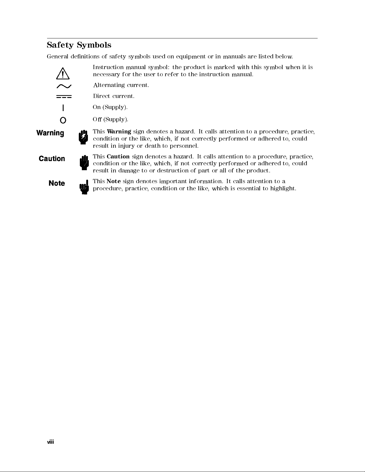
Safety Symbols
General
denitions
Instruction
necessary
Alternating
Direct
On
O
This
condition
result
This
condition
result
This
procedure
of
safety
current.
(Supply).
(Supply).
W
arning
in
injury
Caution
in
damage
Note
symbols used
manual
for
the
user
current.
sign
denotes
or
the
like
or
death
sign
denotes
or
the
like
to
sign
denotes
, practice
on equipment
symbol:
the
to refer
a
,
which,
to
personnel.
a
,which,
or
destruction
important
, condition
product is
to the
hazard. It
if not
correctly performed
hazard.
if not
correctly
of
information.
or
the
or in
manuals are
marked with
instruction manual.
calls attention
It calls
attention to
performed
part
or
all of
the
It
calls
like
,
which
is
essential
listed below
this symbol
to a
procedure
or adhered
a procedure
or
adhered
product.
attention
to
.
when it
,
practice
to
,
could
, practice
to
,
could
to
a
highlight.
is
,
,
viii
Page 9
Document Guide
Please
utilize
Function
the
following
Reference
Explains the
accessed
and
from
accessories
information
GPIB
Programming
Explains
with
report
the
GPIB
.
Also
mechanism,
Manual Supplement
Describes
HP
Instrument
Explains
and
the
Instrument
Reference
Service
Manual
how
B
the
hints
.
Also
following
."
ASIC
B
manuals when
operations commonly
the front
available,
about
panel keys
specications,
the analyzer's
Manual
basic
programming
,
contains
and
for HP
HP
Instrument
User's
usage
of
,
explains
three parts:
ASIC
Interface
information
the
data
Instrument B
B
Handbook
HP
Instrument
all
HP
\HP Instrument
Technique
using the
used for
and softkeys
system performance
features.
methods
on
used
the
transmission
ASIC
ASIC works
B
ASIC
Instrument
," and
analyzer:
measurement and
.It
also
provides
when
remotely
usage
of
all
GPIB
format.
User's
with the
including
B
ASIC commands
BASIC
Handbook
analyzer.
general
Programming T
\HP
Instrument
illustrates all
information
,and
conceptual
controlling
commands
functions
on
the
analyzer
,
the
status
programming examples
. This
manual consists
echnique
B
ASIC
Language
,"
\HP
options
of
Explains
how
instrument.
to
do
performance
tests
,
and
to
adjust,
troubleshoot,
and
repair
the
ix
Page 10

Page 11
Contents
1.
General
INTRODUCTION
ORGANIZA
ANAL
T
ABLE
2.
P
erformance
INTRODUCTION
GENERAL
W
Ambient Conditions
Calibration
P
Recommended
FREQUENCY
Description
Specication
T
Procedure
RF
Description
Specication
T
Procedure
C/N
Description
Specication
T
Procedure
C/N
Description
Specication.. ...... .....
Test Equipment ...... ...... ...... ..
Procedure . . . . . . . . . . . . . . . . . . . . . . .
C/N RA
Description
Specication
Test
Procedure . . . . . . . . . . .
FM DEVIATION TEST ............................ 2-19
Description ................................ 2-19
Specication.. ...... ...... ..... ...... ...... . 2-19
Test Equipment ...... ...... ...... ...... ...... 2-19
Procedure . . . . . . . . . . . . . . . . . . . . . . . . . . . . . . . . . 2-19
SPECTRUM MEASUREMENT RELATIVE LEVEL ACCURACY TEST . . . . . . . 2-25
Description ................................ 2-25
Information
.
.
.
.
.
.
.
.
.
.
.
.
.
.
.
.
..
..
..
TION
OF
SERVICE
YZERS
arm
erformance
est
Equipment
POWER
est
Equipment
RA
est Equipment
MEASUREMENT FLA
Equipment ...... ...... ...... ......
CO
VERED
OF
SERVICE
T
INFORMA
Up
Time
Cycle
MEASUREMENT
.
MEASUREMENT
.
TIO
MEASUREMENT PHASE
..
TIO MEASUREMENT LINEARITY A
TEST
ests
.
.
.
TION
.
.
..
.
T
est
Record
T
est
Equipment
.
.
.
.
.
.
.
.
.
.
.
.
.
.
.
.
.
.
.
.
.
.
.
.
.
.
.
..
.
.
.
.
.
.
.
.
..
..
.
.
.
.
.
.........................
...... ...... ...... ..... ..
MANU
BY
THIS
EQUIPMENT
.
.
.
.
.
.
.
.
.
.
.
.
.
.
.
.
.
.
TEST
.
.
.
.
.
.
.
.
.
.
.
.
.
.
.
.
A
CCURA
.
.
.
.
.
.
.
.
..
..
..
.
..
..
..
..
.
.
.
.
.
.
.
.
TNESS A
.
.
..
AL
.
.
.
.
.
.
.
.
.
.
MANU
.
.
.
.
.
.
.
.
.
.
.
.
.
.
..
..
.
.
.
AL
.
.
.
.
.
.
.
.
.
.
.
.
.
.
.
.
.
.
.
.
.
.
.
.
..
..
..
.
.
.
.
.
.
.
.
.
.
.
.
..
.
.
.
.
.
.
.
.
.
.
.
..
.
.
.
.
.
.
.
.
.
.
.
.
.
.
.
.
.
.
.
.
..
..
..
.
.
.
.
.
.
.
..
..
..
.
.
.
.
.
.
.
.
.
.
.
.
.
.
.
.
.
.
.
.
.
.
.
.
.
.
.
.
.
.
.
..
..
.
.
.
..
.
.
.
.
.
.
.
.
.
.
.
..
.
.
.
.
.
.
.
.
.
.
.
..
.
.
.
.
.
.
.
.
.
.
CY
TEST
.
.
.
..
.
.
.
..
.
.
.
.
.
.
.
.
.
.
NOISE TEST
.
.
.
.
.
.
.
.
.
.
.
.
.
.
.
.
.
.
CCURACY
.
.
.
.
.
...................
CCURACYTEST...... .....
...... ...... ...... ....
.
.
.
.
..
.
.
.
.
.
.
.
.
.
.
.
.
.
.
.
.
.
.
.
TEST .
.
.
.
.
.
.
.
.
.
.
..
.
.
.
.
.
.
.
.
.
.
.
.
.
.
.
..
.
.
.
.
.
.
.
..
.
.
.
.
.
.
.
.
.
.
.
.
.
.
.
.
..
..
.
.
.
.
..
.
.
.
.
.
..
..
..
.
..
..
..
.
.
.
..
..
.
.
.
.
.
.
.
..
.
.
.
.
.
.
.
.
.
.
.
.
.
.
.
..
..
.
.
.
.
.
.
.
..
.
.
.
.
.
..
..
.
.
.
.
.
.
..
..
.
.
.
.
.
.
.
.
.
.
.
.
.
.
.
.
.
.
.
.
.
.
.
.
.
.
.
.
..
.
.
.
.
.
.
.
.
.
.
.
.
.
.
.
.
.
.
.
.
.
.
.
.
.
.
.
.
.
.
.
.
..
.
.
.
.
.
.
.
.
.
.
.
.
.
.
.
.
.
.
.
.
.
..
..
..
..
..
..
.
.
.
.
.
.
.
.
.
.
.
.
.
.
.
...... ....
...... ....
...... .
...... .
......
.
.
..
..
..
.
.
.
.
.
.
..
.
.
.
.
.
.
.
.
.
.
.
.
.
.
.
.
.
.
.
.
.
.
..
..
.
.
..
..
.
.
.
.
.
..
.
.
.
1-1
.
1-1
.
1-3
.
1-4
.
2-1
.
2-1
.
2-1
.
2-1
.
2-1
.
2-1
.
2-2
.
2-3
.
2-3
.
2-3
.
2-3
.
2-3
.
2-5
.
2-5
.
2-5
. 2-5
2-5
.
2-11
. 2-11
. 2-11
.
2-11
.
2-11
2-13
. 2-13
2-13
2-13
2-13
2-16
2-16
2-16
2-16
2-16
Contents-1
Page 12
Specication
T
est Equipment
Procedure
FREQUENCY
Description
Specication
T
est
Equipment
Procedure
DC
POWER
Description
Specication
T
est
Equipment
Procedure
DC
CONTROL
Description
Specication
T
est
Equipment
Procedure
MOD
OUT
Description
Specication
T
est
Equipment
Procedure
DC
POWER
Description
Specication
T
est
Equipment
Procedure
PERFORMANCE
Frequency
P
ower Measurement
C/N
Phase Noise
C/N
Measurement A
C/N
Measurement
FM
Deviation
Spectrum
Frequency
DC
POWER
DC
CONTROL
MOD
OUT
DC POWER Current T
..
..
.
TRANSIENT FREQUENCY
..
..
.
.
.
V
OL
T
A
.
.
.
.
.
.
.
V
OL
.
.
.
.
.
.
.
LEVEL
.
.
.
.
.
.
..
CURRENT
.
.
.
.
.
.
.
TEST
Measurement
T
est
Measurement
Transient
V
oltage
V
oltage
V
oltage
..
.
.
.
.
.
.
.
.
.
.
.
.
.
.
.
.
.
.
.
.
.
.
.
.
.
.
.
.
.
.
.
.
.
.
.
.
.
.
.
.
GE
A
CCURA
.
.
.
.
.
.
.
.
.
.
.
.
.
.
.
.
.
.
.
.
.
.
.
.
T
A
GE
A
CCURA
.
.
.
.
.
.
.
.
.
.
.
.
.
.
.
.
.
.
.
.
.
.
.
.
A
CCURA
.
.
.
..
.
.
.
T
est
A
T
CY
TEST
.
.
.
.
.
.
.
.
.
.
.
.
.
.
.
..
.
.
.
MEASUREMENT A
..
.
.
.
..
.
.
.
..
.
.
.
.
.
.
.
RECORD
T
est
A
ccuracy
.
.
.
.
ccuracy
ccuracy
.
.
Frequency
T
est
est .
est . . . . .
.
.
Relative
.
T
est
.
T
T
.
.
..
.
.
.
.
.
.
.
.
.
.
.
.
.
.
.
CY
TEST
.
.
.
.
.
..
..
CY
.
.
.
.
.
.
..
.
.
..
..
.
.
.
.
.
.
.
.
.
.
.
.
.
T
est
.
.
est
(Flatness)
est
(Linearity)
.
.
Level
A
ccuracy
.
.
..
.
.
.
.
.
.
.
.
.
..
..
..
..
..
..
.
.
.
.
..
..
..
..
..
..
..
.
.
.
.
.
..
..
..
..
..
..
..
.
.
.
.
A
CCURA
.
.
.
..
.
.
.
..
.
.
.
..
.
.
..
.
.
.
.
.
..
.
.
.
..
..
..
..
..
TEST
.
..
..
.
..
..
.
..
..
..
.
.
.
.
.
.
.
.
.
..
..
..
..
.
.
.
.
CCURACY
.
.
.
.
.
.
.
.
.
.
.
.
.
.
.
.
.
.
.
.
.
.
.
.
.
.
.
.
.
.
.
.
.
.
.
A
ccuracy
.
.
.
.
..
..
.
.
.
.
.....................
..
.
..
.
.
.
.
.
..
.
.
.
.
.
.
.
.
.
.
T
est
.
.
..
..
..
..
..
..
..
..
.
..
..
..
..
.
.
.
.
..
.
.
.
.
.
.
.
.
.
.
.
.
.
.
.
.
.
.
.
.
.
.
.
.
.
..
.
.
..
..
.
.
CY
..
..
..
..
..
..
.
.
..
.
.
.
.
.
.
.
.
.
TEST
.
.
.
.
.
.
.
.
.
.
.
..
T
est
.
..
..
TEST
..
..
..
..
..
..
..
.
.
.
.
..
.
.
.
.
.
.
.
.
.
..
.
.
.
.
.
.
.
.
.
.
.
.
.
.
.
.
.
.
.
.
.
.
.
.
.
.
.
..
.
.
..
.
.
.
..
..
.
.
.
..
.
.
.
.
.
.
.
.
.
.
.
.
.
.
.
.
.
.
.
.
.
.
.
.
.
.
.
.
.
.
.
.
..
.
.
.
.
.
.
.
.
.
.
.
.
.
.
.
.
.
..
.
.
.
.
.
.
..
..
.
.
.
.
.
.
.
.
.
.
.
.
.
.
.
.
.
.
.
.
.
.
.
.
.
.
.
.
.
.
.
.
.
.
.
.
.
.
.
.
.
.
.
.
.
.
.
.
.
..
.
.
..
.
.
.
.
.
.
..
.
.
.
.
.
.
..
..
.
.
.
.
.
.
.
.
.
.
.
.
.
.
.
.
.
.
.
.
.
.
.
.
.
.
.
.
.
.
.
.
.
.
.
.
.
.
.
.
.
.
.
.
.
.
.
.
.
.
..
.
.
..
.
.
.
.
.
..
.
.
.
.
.
.
.
.
.
.
.
.
.
.
.
.
.
.
.
.
.
.
.
.
.
.
.
.
.
.
.
.
.
.
.
.
.
.
.
.
.
.
..
.
.
.
..
.
.
.
.
.
.
.
.
.
.
.
.
.
.
.
..
.
.
.
.
..
.
.
.
.
.
.
..
.
.
.
.
.
.
.
.
.
.
.
.
.
.
.
.
.
.
.
.
.
.
.
.
.
.
.
.
.
.
.
.
.
.
.
.
..
.
.
..
.
..
.
..
.
.
.
.
..
..
.
.
.
.
..
.
.
..
..
.
.
.
.
.
..
.
.
.
.
.
.
..
.
.
.
.
.
.
.
.
.
.
.
.
.
.
.
.
.
.
.
.
.
.
.
.
.
.
.
.
.
.
.
.
.
.
.
.
.
.
.
.
.
.
.
.
.
..
.
.
..
.
.
.
.
.
.
.
.
..
. 2-40
.
.
.
.
.
2-25
2-25
2-25
2-28
2-28
2-28
2-28
2-28
2-30
2-30
2-30
2-30
2-30
2-32
2-32
2-32
2-32
2-32
2-34
2-34
2-34
2-34
2-34
2-36
2-36
2-36
2-36
2-36
2-38
2-38
2-38
2-38
2-39
2-39
2-39
2-40
2-40
2-41
2-41
2-41
3. Adjustments and Correction Constants
Introduction . . . . . . . . . . . . . . . . . . . . .
Safety Considerations .... ...... ...... ....
RequiredEquipment.......... ...... .....
Adjustment Program . . . . . . . . . . . . . . . . . . . . .
Warm-up for A
Instrument Cover Removal . . . . . . . . . . . . . . . . . . . . . . . . . . 3-3
Order Of Adjustments and Correction Constants . . . . . . . . . . . . . . . . 3-3
Preparation for Using the Adjustment Program ........ .... .... 3-4
REFERENCE FREQUENCY ADJUSTMENT .................. 3-8
Required Equipment . . . . . . . . . . . . . . . . . . . . . . . . . . . . 3-8
Procedure..... ...... ...... ...... ...... .... 3-8
THIRD MIXER FEEDTHROUGH ADJUSTMENT ................ 3-10
Contents-2
djustments and Correction Constants
............
...... ..
........
.......
...... ...... ..
3-1
3-1
3-2
3-2
3-3
Page 13
Required
Procedure
THIRD
EEPROM
CRYST
FV
DC
DC
MOD
DC
RF
RF
SPECTRUM
IF AMP
Required
Procedure
WRITE-ID AND
Required
Procedure
AL
Required
Procedure
CONVERTER
Required
Procedure
POWER
T
est
Equipment
Procedure
CONTROL
Required
Procedure
OUT
Required
Procedure
POWER
T
est
Equipment
Procedure
POWER
Required
Procedure
POWER
Required
Procedure
Required
Procedure
Equipment .
..
.
GAIN
Equipment .
..
.
Equipment
.
.
.
FIL
TER
FREQUENCY
Equipment
.
.
.
CORRECTION
Equipment
.
.
.
V
OL
T
A
GE
.
.
.
V
OL
T
A
Equipment
.
.
.
LEVEL
Equipment
LINEARITY
Equipment
FLA
Equipment .
Equipment
CORRECTION
.
.
..
CURRENT
.
.
.
.
.
.
TNESS
..
.
MEASUREMENT CORRECTION
.
.
.
..
.
.
.
.
.
.
.
.
.
.
.
ADJUSTMENT
.
.
.
.
.
.
.
.
.
.
.
.
.
INITIAL
.
.
.
.
.
.
.
.
.
.
.
.
.
.
.
.
.
.
.
.
.
.
.
.
CORRECTION
.
.
.
.
.
.
.
.
.
.
GE
CORRECTION
.
.
.
.
.
.
.
.
.
.
.
..
.
.
CORRECTION CONST
..
..
.
.
..
.
.
CORRECTION
.
.
.
.
.
.
.
.
CORRECTION
.
.
.
.
.
.
.
.
.
.
.
.
.
.
.
CORRECTION
.
.
.
.
.
.
RESPONSE
.
.
.
.
.
.
CONST
.
.
.
.
.
.
.
.
.
.
.
.
.
.
.
.
.
.
CONST
.
.
.
.
.
.
.
.
.
.
.
.
.
.
.
.
.
.
.
.
.
.
.
.
.
.
.
.
.
.
.
.
.
.
.
.
.
.
.
..
CONST
.
..
.
.
.
.
.
.
.
.
.
.
.
.
.
.
.
.
..
.
.
.
.
.
.
.
..
.
.
.
.
..
.
.
.
.
..
ANTS
.
..
..
..
..
..
CONST
.
.
.
.
.
.
ANTS
..
..
.
.
.
.
.
.
.
.
.
CONST
.
.
.
.
.
.
CONST
.
.
.
.
.
.
.
.
.
.
.
.
ANTS
.
.
.
.
.
.
..
..
..
.
.
.
.
.
.
.
.
..
..
..
..
..
CONST
.
.
..
..
..
CORRECTION
.
.
..
..
..
.
.
..
..
..
.
..
..
.
ANTS
.
.
.
..
.
.
.
..
.
.
.
ANTS .
.
.
.
.
.
.
ANTS .
.
.
.
.
.
.
ANTS
.
.
.
.
.
.
CONST
.
.
..
..
..
..
..
..
..
.
.
..
.
.
.
.
.
.
.
.
..
..
.
.
.
..
..
.
.
.
.
.
.
.
.
.
.
.
.
.
.
.
.
.
ANTS
..
..
ANTS
.
.
..
.
.
.
.
.
.
.
.
.
.
.
.
.
.
.
..
..
..
..
..
..
..
..
..
.
.
CONST
..
..
.
.
..
.
.
.
.
.
..
.
.
.
.
.
..
.
.
.
.
.
..
.
.
.
.
.
.
.
.
.
.
.
.
.
.
.
.
.
.
.
.
.
.
.
.
.
.
.
.
..
..
.
.
..
..
..
.
.
.
.
.
..
.
.
.
..
.
.
.
.
.
.
.
.
..
.
.
.
.
.
.
.
.
.
.
.
..
.
.
.
..
.
.
.
.
..
..
..
..
..
.
.
.
.
.
.
ANTS
.
.
.
.
..
.
.
.
.
.
.
.
.
.
.
.
.
.
.
.
.
.
.
.
.
.
.
.
.
.
.
.
.
.
.
..
.
.
.
.
.
.
..
.
.
.
.
.
.
..
.
.
..
..
.
.
.
.
.
.
.
.
.
.
.
.
.
..
.
.
.
.
.
.
.
.
.
.
.
.
.
.
.
.
.
.
.
.
..
.
.
.
..
.
.
.
.
.
.
.
.
.
..
.
.
.
.
.
.
.
.
..
.
.
..
..
.
.
.
.
.
.
.
.
.
.
.
.
.
.
.
.
.
.
.
.
.
.
.
.
.
.
.
.
.
.
.
.
.
.
.
.
..
.
.
..
..
.
.
.
.
.
.
.
.
..
.
.
.
.
.
.
.
.
..
.
.
..
.
.
.
.
..
.
.
.
.
.
.
.
.
.
.
.
.
.
.
.
.
.
.
.
.
.
.
.
.
.
.
.
.
.
.
.
.
.
.
.
.
.
.
.
.
.
.
.
.
.
.
.
.
.
.
.
.
.
.
.
.
.
3-10
3-10
3-11
3-11
3-11
3-13
3-13
3-13
3-14
3-14
3-14
3-15
3-15
3-15
3-16
3-16
3-16
3-17
3-17
3-17
3-18
3-18
3-18
3-19
3-19
3-19
3-20
3-20
3-20
3-22
3-22
3-22
3-23
3-23
3-23
4.
Overall
INTRODUCTION
TROUBLESHOOTING
ST
INSPECT THE POWER ON SEQUENCE
Check the F
Check the Front P
Check Error Message . . . . . . . . . . . . . . . . . . .
OPERATOR'S CHECK
Test Equipment ...... ...... ...... ..
Procedure to check the source group
Procedures to check the receiver group . . . . . . . . . . . . . . . . . . .
PERFORMANCE TESTS FAILURE TROUBLESHOOTING ............ 4-9
Perform Adjustments and Correction Constants ...... ...... ... 4-9
TROUBLESHOOTING GPIB SYSTEM ..................... 4-10
Check the GPIB system with the signal generator .... ...... .... 4-10
Check the External Controller ...... ...... ...... ..... 4-11
Troubleshooting
ART
HERE
.
.
.
.
.
.
.
SUMMARY
.
.
..
.
.
.
.
an.......
anel LED
...................
.
.
.
.
.
.
.
.
..
..
..
..
.
.
.
.
.
.
.
.
.
.
.
..
..
..
..
..
..
.
.
.
.
.
.
.
.
.
.
.
.
.
..
.
.
.
.
.
.
.
.
.
.
..
.
.
.....
...... ..... ...... ...... .
......
..................
..................
...... ...... ...
...... ...
...... ...
...... ....
..
.
4-1
.
4-1
.
4-3
4-4
4-4
4-4
4-4
4-5
4-5
4-5
4-6
Contents-3
Page 14
5.
Power
INTRODUCTION
ST
ART HERE
1.
Check Error
2.
Check the
3.
Check the
A50
4.
Check
Measure
5.
Check
6.
Run
Internal
FIND
OUT
1.
Check
2.
Check
FIND
OUT
1.
Disconnect
2.
Disconnect
3.
Remove
FIND
OUT
1.
Check
2.
Check
3.
Disconnect
4.
Remove
TROUBLESHOOT
1.
Troubleshoot
2.
Troubleshoot
TROUBLESHOOT
1.
Measure
Supply Troubleshooting
..
.
.
.
.
.
.
.
.
.
.
.
.
.
F
an
A50
Shutdown
the
A1
the
A1
the
A2
the
Internal
T
est
4:
WHY
THE
the
Line
the
A50
WHY
THE
the
the
Assemblies
WHY
THE
the
A40
the
A50
Cables
Assemblies
A2
Messages
is
SHUTDOWN
LED
+5
+5
Seven
A2
V
SHUTDOWN
Cable
Cable
Pre-Regulator
DC-DC
THE
the
the
A2
POST-REGULA
P
ost
.
Rotating
.
.
VD
LED
VD
V
oltage
LEDs
T
est
4:
POST
F
AN
IS
NOT
oltage
,
Selector
A50
SHUTDOWN
from
from
.
.
A1
+5
VD
Converter
on the
..
F
AN AND
F
an
..
A50
DC-DC
Regulator
.
.
A2
REGULA
.
A1 CPU
..
.
.
.
.
.
.
.
.
..
.
.
.
.
.
.
.
.
.
.
LED
.
.
.
.
.
.
.
.
.
.
.
.
.
.
.
.
.
.
.
.
POST
REGULA
TOR
ROT
A
TING .
Switch
LED
.
.
LED
the
A50J3
the
A1J10
.
.
.
.
.
LED
IS
NOT
.
.
.
.
.
.
.
.
.
.
THE A50
.
.
.
.
.
Converter .
TOR
Output
V
.
..
..
.
.
.
.
.
.
.
.
.
.
.
.
.
.
.
Setting,
.
.
IS
.
.
.
.
ON
.
..
.
..
.
.
.
.
DC-DC
.
.
.
.
oltages
..
..
..
..
.
..
..
..
..
.
.
.
.
.
..
..
..
..
.
.
..
.
..
..
TOR
.
.
..
..
..
..
and
.
.
..
OFF
.
.
.
.
.
.
.
..
.
.
..
STEADIL
..
..
..
..
.
.
.
.
.
.
.
.
CONVERTER
.
.
.
.
.
.
.
.
.
.
.
.
.
.
..
..
..
..
..
..
..
..
..
.
.
..
..
..
.
.
..
..
.
.
.
..
.
.
.
.
.
.
.
.
.
.
.
.
..
..
..
..
..
..
Fuse
..
..
..
.
.
Y
.
.
.
.
.
.
.
..
..
..
..
..
..
.
..
..
..
..
.
.
.
..
..
.
.
.
.
.
.
.
.
.
.
.
.
.
.
.
.
.
.
.
.
.
.
..
.
..
..
..
.
.
.
.
.
.
.
..
.
.
.
.
..
.
.
..
.
.
.
.
.
.
..
.
.
.
.
.
.
.
.
.
.
.
.
.
.
.
.
.
.
..
.
.
..
..
..
.
.
.
.
.
.
.
.
..
.
.
.
.
..
.
.
.
.
.
.
.
.
.
.
.
.
.
.
.
.
.
.
.
.
.
.
.
.
.
.
.
.
.
.
.
.
..
.
..
.
.
.
.
.
.
.
.
.
.
.
.
.
.
.
.
.
.
.
.
.
.
.
.
.
.
.
.
.
.
.
.
.
.
.
.
.
.
.
.
.
.
.
.
.
.
.
.
.
.
.
.
. 5-2
.
.
.
.
.
.
.
.
.
.
.
.
.
.
.
.
.
.
.
.
.
.
.
.
.
.
.
.
.
.
.
.
.
.
..
.
.
.
. 5-12
.
.
.
.
.
. 5-15
5-1
5-2
5-2
5-2
5-3
5-4
5-4
5-4
5-5
5-6
5-7
5-7
5-7
5-8
5-8
5-8
5-8
5-9
5-9
5-9
5-10
5-10
5-12
5-13
5-15
6.
Digital Control
INTRODUCTION
A1
CPU
Replacement
FIRMW
ST
TROUBLESHOOT THE A51 GSP and A52 LCD . . . . . . . . . . . . . . . . .
ARE
Ordering
ART
HERE
1.
Check
Check
Check
2.
Check
3. Check the A1 DRAM and Flash Memory
4. Check the A1 V
5. Check the A30 Front Keyboard
6.ChecktheA53FDD.................
7. Check the A32 I-B
8. Check the A17 24 bit I/O P
1. Run the Internal T
2. Check the A52 LCD(Liquid Crystal Display) . . . . . . . . . . . . . . . . 6-10
Troubleshooting
..
INST
ALLA
the
Firmware
.
.
.
the
P
ower
the
A1
Eight
Error
Messages
the
A1
CPU
olatile Memory . . . .
.
.
.
.
.
.
.
.
.
.
.
.
.
.
.
.
.
.
.
.
.
.
.
.
.
.
.
.
.
.
.
.
..
..
.
TION
.
On
ASIC Interface and the mini-DIN Keyboard
est 3: A51 GSP
Diskette
.
.
.
Sequence
LEDs
.
..
.
.
.
.
.
.
.
.
.
..
..
..
.
.
.
.
.
.
.
.
.
.
.
.
.
.
.
.
.
.
..
..
..
.
.
.
.
.
.
.
.
.
.
.
.
..
..
.
.
.
.
.
.
.
.
.
.
.
..
..
.
.
..
..
..
..
..
..
.
.
.
.
.
.
.
.
.
.
.
.
..
.
.
..
...............
..................
......
ort ..............
................
...... ...... ...
..
.
.
..
..
.
.
.
.
.
.
.
.
..
.
.
.
.
.
..
..
.
.
.
.
.
.
.
.
..
..
.
.
..
..
.
.
.
.
.
.
.
.
.
.
.
.
.
.
.
.
..........
..... ..
........
....
.
.
.
.
.
.
.
.
.
.
.
.
.
.
.
.
.
.
.
.
..
.
6-1
.
6-3
.
6-4
6-4
.
6-5
6-5
6-5
.
6-6
6-6
6-7
6-8
6-8
6-8
6-9
6-9
6-10
6-10
Contents-4
Page 15
7.
Source Group
INTRODUCTION
SOURCE
ST
ART HERE
1.
Check A6's
2.
Check Option
3.
Bypass
4.
Check
5.
Check
6.
Check
7.
Check
8.
Receiver
INTRODUCTION
RECEIVER
ST
ART
1.
Check
2.
Check
3.
Check
4.
Check
5.
Check
6.
Check
7.
Check
8.
Check
Troubleshooting
..
.
.
.
.
.
.
GROUP TROUBLESHOOTING
.
.
.
.
.
.
.
.
.
A/D
A70
DC
A3/A13
MOD
REF
Group
GROUP
HERE
the
A6
A5
Measurement
A11
the
the
the
Converter
001
DC
.
.
.
.
POWER/DC
Source
OUT
signal
OSC
on
A6
Troubleshooting
.
.
.
.
TROUBLESHOOTING
.
.
.
.
.
Rear
P
anel
Spectrum
2nd
Thermometer
outputs
Residual FM
Frequency Transient
Analyzer
PLL
Functions
from
.
CONTROL
.
.
.
.
CONTROL
.
.
.
.
.
.
.
.
.
.
.
.
.
.
.
Output
.
.
.
.
.
A10
..
.
.
.
.
.
SUMMARY
.
.
..
..
.
.
.
.
.
Outputs
.
.
.
..
Outputs
.
.
.
.
.
.
.
.
.
.
.
.
.
.
.
.
.
.
..
SUMMARY
..
..
..
signals
.
.
1st
.
(40MHz Output/INT
.
.
.
.
.
.
.
.
.
.
.
.
.
.
.
..
Mixer
.
.
.
.
measurement .
..
..
.
.
.
..
.
.
.
.
.
.
..
..
.
.
..
.
..
.
.
..
.
..
.
.
..
.
..
.
..
.
.
..
.
.
..
..
..
..
.
.
..
.
.
.
..
..
.
.
..
.
.
..
..
.
.
..
.
.
..
..
..
.
.
.
.
.
.
.
.
.
.
.
.
..
.
.
.
.
..
.
.
..
..
.
.
.
.
.
.
..
..
..
.
.
.
.
.
.
.
.
.
.
.
.
.
.
..
.
.
.
.
..
.
.
..
..
..
.
.
.
..
..
..
.
.
.
.
.
.
.
REF
.
.
.
.
..
.
.
.
.
.
.
.
..
..
.
.
.
.
.
..
..
..
.
.
.
..
.
.
.
.
.
.
.
.
.
.
.
.
.
.
..
.
.
.
OUTPUT)
.
.
.
.
.
.
.
.
.
.
.
.
.
.
.
.
.
.
.
.
.
.
..
.
.
..
..
.
.
..
.
.
.
.
.
.
.
.
..
.
.
.
.
.
.
.
.
.
.
.
.
.
.
.
.
.
..
.
.
..
..
.
.
..
.
.
.
.
.
.
.
..
.
.
.
.
.
.
.
.
.
.
.
.
.
.
..
.
.
.
.
.
7-1
. 7-2
.
7-4
.
7-4
7-4
.
7-5
.
7-5
.
7-7
.
7-8
.
7-8
.
8-1
8-2
.
8-4
.
8-4
.
8-4
.
8-7
.
8-9
.
8-10
.
8-10
8-12
.
8-13
9.
Service
INTRODUCTION
SERVICE
N
N
N
N
TESTS
N
N
N
N
T
Diagnostic T
Test Descriptions . . . . . . .
K
ey
Menus
.
N
NN
N
TESTS
N
N
N
N
SERVICE
N
N
N
N
SERVICE
N
N
N
N
FIRMWARE
NN
NN
EXECUTE
N
N
N
N
INTERNAL
N
N
N
N
EXTERNAL
N
N
N
N
DISPLAY
est Status
MENU
N
N
N
N
N
N
N
N
N
N
N
N
N
N
N
N
N
N
NN
N
N
N
N
N
N
NNNNNN
INTERNAL TESTS
0: ALL INT
1: A1 CPU
2: A1 V
3: A51 GSP
4: A2 POST REGULA
5through10:N/A............................ 9-9
NNNNNNNNNNNNNNNNNNNNNNNNNNNNNNNNNNNNNNNNNNNN
EXTERNAL TESTS
11: FRONT PANEL DIAG. ........................ 9-9
12: DSK DR FAULTISOL'N........................ 9-9
13: 24 BIT I/O PORT . . . . . . . . . . . . . . . . . . . . . . . . . . . 9-9
14 through 20: N/A .... ...... ...... ...... .... . 9-10
.
N
N
N
N
N
N
N
N
N
N
N
N
N
N
N
NN
N
N
N
N
N
N
N
N
N
NN
NN
N
N
N
N
N
N
NN
NN
N
N
N
N
N
N
N
N
N
MENU .
N
N
N
N
N
N
N
N
N
N
N
N
N
N
N
N
N
N
N
N
N
N
N
N
N
N
N
N
N
NN
NN
N
N
N
N
N
N
N
NN
NN
NN
NN
N
N
NN
NN
NN
NN
N
N
N
N
N
N
N
NNNNNNNNNNNNNNNNNNNNNNNNN
.
.
.
.
N
N
N
N
N
N
N
N
N
N
N
N
N
N
N
N
N
INSTRUMENT
N
N
N
MODES
N
N
N
N
NN
TEST
NN
N
N
N
N
N
N
TESTS
OLATILE MEMORY .
N
N
N
N
N
N
N
N
N
N
N
N
N
N
N
N
N
N
N
N
N
N
N
N
N
NN
NN
N
N
N
REVISION
.
NN
NN
NN
N
N
N
N
N
N
(
N
N
N
N
N
N
N
N
N
N
N
N
N
N
N
N
TESTS
N
N
N
N
N
N
N
N
N
N
N
N
N
NN
NN
TESTS
N
N
N
N
N
N
N
NN
NN
NN
NN
.
.
ests .......
NNNNNNNNNNNNN
...
....
..............
.
.
.
..
.
.
.
.
.
.
.
.
.
.
.
.
.
.
.
.
.
.
.
.
.
.
.
.
.
.
.
.
.
.
.
.
.
.
.
.
.
.
.
.
.
.
.
..
.
.
.
.
.
.
.
.
.
.
.
.
.
.
.
.
.
.
.
.
.
.
.
.
.
..
.
.
.
.
.
.
N
N
N
N
N
NN
N
N
N
N
N
N
N
.
.
.
.
.
.
.
.
.
.
.
.
.
.
.
.
..
.
.
.
.
(
:DIAG:SERV:MODE
N
N
N
N
N
N
N
N
N
N
N
(
:DIAG:FREV?
.
.
.
.
.
.
.
:DIAG:TEST:EXEC
N
N
(
:DIAG:TEST
N
(
:DIAG:TEST
(
:DIAG:TEST
.
.
.
.
.
.
.
.....................
.........................
.........................
TOR .............
............................ 9-9
{OFF|ON|0|1}
)
.
..
..
.
.
.
.
.
.
.
)
.
.
.
.
.
0
)
.
.
.
.
.
11
)
.
.
.
.
..
21
)
..
..
..
.
..
.
.
.
.
...... ...... ...... .....
...... ..... ...... ......
...... ...... ...... .....
...
)
.
.
.
.
.
.
..
.
.
.
.
.
.
.
.
.
.
.
.
..
..
..
..
.
.
.
.
.
.
.
.
.
.
.
.
.
.
.
.
.
..
..
..
..
..
..
.
.
.
.
..
..
.
.
.
.
.
.
.
.
.
.
.
.
.
..
.
.
...... .
..............
...... .....
.
.
..
.
.
.
.
.
..
.
.
.
.
.
.
.
.
.
.
.
.
.
.
.
.
.
...
..
.
.
.
.
.
.
.
.
.
.
.
.
..
.
.
.
.
.
.
.
.
..
9-1
9-3
9-3
9-3
9-3
9-4
9-5
9-5
9-6
9-6
9-6
9-6
9-7
9-8
9-8
9-8
9-8
9-8
9-9
9-9
Contents-5
Page 16
N
N
N
N
N
N
N
N
N
N
NN
NN
NN
NN
NN
NN
N
N
N
N
N
N
N
N
N
N
N
N
N
NN
NN
DISPLAY
21:
TEST P
22:
TEST P
23:
TEST P
24:
TEST
25:
TEST
SERVICE
N
N
N
N
BUS
N
N
N
N
MISC
N
N
N
N
CORRECTION
N
N
N
N
A2/A8
N
N
N
N
A3
N
N
N
N
A5
N
N
NN
A6
N
NN
NN
A70
Service
BUS
N
N
N
N
BUS
N
NN
NN
DC
N
N
N
N
FREQ
N
N
N
N
WAIT
Bus
Bus
Bus
DC
MODES
N
N
N
N
N
N
N
N
N
N
N
N
N
N
NN
NN
NN
NN
N
N
N
MEAS
N
N
N
N
N
N
N
N
N
N
N
N
N
N
N
N
N
NN
N
N
N
N
N
NN
NN
N
N
NN
.
N
NN
N
.
NN
NN
.
N
N
N
N
N
N
MEASUREMENT
N
N
N
NN
NN
NN
NN
NN
N
N
N
N
BUS [FAN
N
N
N
N
N
N
N
N
N
N
N
N
N
N
N
N
N
N
Measurement
Measurement
Measurement
Bus
0:
1:
2:
3:
4:
5:
6:
7:
8:
9:
10:
11: [A2] F
12: [A2] +65 V (2.0605 U)
13 through 19: Not Assigned . . . . . . .
20: [A3] +20VB . . . . . . . . . .
21: [A3]05VB ..................
22: [A3] +25V
23: [A3] -5V
24: [A3] DC POWER . . . . . . . . . . . . . . . . . . . . .
25: [A3] DC CONTROL . . . . . . . . . . . . . . . . . . . . . . . . . . 9-17
26 through 29: Not Assigned . . . . . . . . . . . . . . . . . . . . . . . 9-17
30: [A5] VCO VTUNE .......................... 9-17
31: [A5] 2ND IF DC OFFSET . . . . . . . . . . . . . . . . . . . . . . . 9-17
32 through 39: Not Assigned . . . . . . . . . . . . . . . . . . . . . . . 9-17
40: [A6] AD VREF . . . . . . . . . . . . . . . . . . . . . . . . . . . . 9-17
41: [A6] REF LOOP VTUNE ....................... 9-17
[ON]
N
N
NN
NN
NN
NN
N
N
N
N
N
N
MENU
NN
NN
NN
N
N
N
N
N
N
N
N
N
NN
NN
.
.
.
.
.
.
..
..
..
..
.
Modes
N
N
N
N
N
N
N
N
N
N
N
N
N
N
N
N
MEAS
ON
N
N
N
N
N
N
N
N
N
N
N
N
N
NN
NN
N
N
N
N
N
N
N
N
N
NN
NN
N
N
N
BUS
[OFF]
N
N
N
NN
NN
N
N
N
N
N
N
N
N
N
COUNT
Node
NONE
[A2] +5
[A2]
0
15
[A2]
0
12.6
[A2]
0
5
[A2]
+5
[A2]
+5.3
[A2]
+8.5
[A2]
+15
[A2] +15
[A2]
+22
NN
TESTS
ATTERN
ATTERN
ATTERN
P
A
P
A
N
N
N
N
N
.
N
N
N
N
N
.
.
..
.
N
N
N
NN
NN
NN
N
N
N
N
N
N
N
N
.
AN POWER
.
.
.
.
.
.
..
..
..
..
..
1
.
.
.
.
.
.
.
.
.
.
..
..
2
.
.
.
.
.
.
.
.
.
.
..
..
3
.
.
.
.
.
.
.
.
.
.
..
..
TTERN
TTERN
MENU
N
N
N
N
N
N
.
N
N
N
NN
NN
CONSTANTS
.
..
.
.
.
NN
NN
N
N
off
N
N
N
N
N
N
PWR]
N
N
N
N
N
N
(
:DIAG:SERV:BUS:WAIT
Descriptions
.
V
(A
V
V
(
V
(2.025
V
V
V
V
V
C .. ...... ...... .... ..
4
.
.
.
.
.
.
..
..
..
..
5
.
.
.
.
.
.
..
..
..
..
.
.
.
.
.
.
.
.
.
.
.
.
.
N
.
.
.
.
.
.
.
.
.
.
.
.
.
..
.
.
.
.
.
.
.
.
.
..
..
NN
NN
N
N
N
N
N
N
N
N
N
N
N
N
N
N
N
N
N
.
.
.
.
.
.
.
.
..
..
..
..
..
..
.
.
.
.
.
..
.
.
.
.
.
.
.
.
.
.
.
.
.
.
.
.
.
.
.
.
.
.
.
.
.
.
.
.
.
.
.
.
.
.
.
.
.
..
MENU
N
N
N
N
N
N
N
(
:DIAG:SERV:BUS:STAT {ON|OFF|1|0}
N
N
N
N
N
N
N
N
N
N
(
N
N
N
N
(
:DIAG:SERV:BUS:FREQ
.
Procedure
V
alues
.
.
UX)
(
0
1.92
V
(
0
2.124
0
2.025
(2.1465
(1.8955
(A
UX)
(1.92
(2.002
C ... ...... ...... ....
.
.
.
.
.
:DIAG:SERV:BUS:DC
<
.
.
..
.
.
.
.
.
.
..
.
.
..
.
.
.
.
.
.
.
.
.
.
.
.
.
.
.
(2.025
U)
U)
U)
U)
.
.
U)
.
U)
.
.
.
.
.
U)
.
U)
.
(1.92
U)
.
.
.
U) .
.
.....
.....
.
.
.
.
.
.
.
.
.
.
.
.
.
.
.
.
.
.
.
.
.
.
.
.
.
.
.
.
.....................
..
.
.
..
.
.
.
.
.
.
.
.
.
.
.
.
.
.
.
.
.
.
.
.
.
.
.
.
.
.
.
<
numeric
<
numeric
numeric
.
.
.
.
.
.
.
.
.
.
.
.
.
.
.
.
.
.
.
.
.
.
.
.
.
.
.
..
..
.
.
.
.
.
.
.
.
.
.
.
.
.
.
..
.
.
.
...... ...... ...... .
...... ...... ...... .
..
..
..
..
..
.
.
.
.
.
.
.
.
.
.
.
.
.
.
.
.
.
.
.
..
>
)
.
.
.
.
.
.
.
.
.
.
.
.
.
.
.
.
.
.
.
.
.
.
.
.
.
.
.
.
.
.
..
..
.
..
..
.
.
.
..
.
.
.
..
.
.
.
..
..
..
.
.
.
.
...... ...... ....
..
..
.
.
.
.
..
..
..
..
..
..
..
..
..
..
..
..
..
..
..
.
..
..
..
.
..
..
..
.
..
..
.
.
.
.
.
.
.
.
.
.
.
.
..
.
.
.
.
.
.
.
.
.
.
.
.
.
.
.
.
.
.
.
.
..
.
.
.
.
..
..
.
..
..
..
.
.
..
..
.
.
.
.
.
.
.
.
.
.
.
.
.
.
.
.
.
.
.
) .
.
.
.
>
)
.
.
.
.
.
.
>
)
.
.
.
.
.
.
.
.
.
..
..
.
.
.
.
.
.
.
.
.
.
.
.
.
.
.
.
.
.
.
.
.
.
.
.
.
.
.
.
.
.
.
.
.
.
.
.
..
.
.
.
.
.
.
.
.
.
.
..
.
.
.
..
..
.
.
.
.
.
..
..
.
.
.
.
.
.
.
..
.
.
.
.
.
..
..
.
.
.
..
..
..
.
..
..
..
.
..
..
..
..
..
.
.
.
.
.
.
...... .....
...... ....
..........
......
.
.
..
..
..
.
.
.
.
.
.
.
.
.
.
.
.
.
.
..
..
.
.
.
.
.
.
.
.
.
.
.
.
.
.
.
.
.
.
.
.
.
.
..
.
.
..
.
.
.
.
.
.
.
.
.
.
.
.
.
.
.
.
.
.
.
.
.
.
.
.
..
.
.
.
.
.
.
.
.
.
.
.
.
.
.
.
.
.
.
.
.
.
.
.
.
.
.
.
.
.
.
.
.
.
.
.
..
.
.
.
.
.
.
.
..
.
.
.
.
.
.
.
.
.
.
.
.
.
.
.
9-10
.
9-10
.
9-10
.
9-10
.
9-10
.
9-10
.
9-11
.
9-11
.
9-11
.
9-11
. 9-12
9-12
.
9-12
.
9-12
.
9-12
.
9-12
.
9-13
.
9-13
.
9-13
9-14
.
9-14
. 9-14
.
9-14
.
9-15
.
9-15
.
9-15
.
9-15
.
9-15
.
9-15
.
9-15
.
9-15
.
9-15
.
9-15
.
9-16
.
9-16
. 9-16
9-16
9-16
9-16
9-16
9-16
9-16
9-16
9-16
Contents-6
Page 17
42:
[A6] FIXED
43:
[A6] FN
44:
[A6] PEAK
45:
[A6] GND
46
through 49:
50:
[A6] SA
51:
[A6]
MONITOR
Frequency
0:
1:
2:
3:
4
through
10:
11:
12:
13:
14:
CORRECTION
N
N
N
N
N
N
N
N
N
N
N
N
XTAL
N
N
N
N
N
N
N
NN
NN
NN
FV
ON
N
NN
NN
NN
NN
N
N
N
DCPOW
N
N
N
N
N
N
N
N
N
N
N
N
DCPOW
N
N
N
N
N
N
N
N
N
N
N
N
DCCTL
N
N
N
N
N
N
N
N
N
N
N
N
MOD
N
N
N
N
N
N
N
NN
N
N
N
POW
N
N
NN
N
N
N
N
N
N
N
N
POW
N
N
N
N
N
N
N
N
N
N
N
N
POW
N
N
N
N
N
N
N
N
N
N
N
N
NOISE
N
N
N
N
N
N
N
N
N
NN
NN
SPEC
N
NN
NN
NN
NN
N
N
N
SPEC
A2/A8
N
N
N
N
N
N
N
N
N
N
N
N
RF
ATTEN:
N
N
N
N
N
N
N
N
N
N
N
N
POW
A3/A13 CONTROL
N
N
NN
NN
NN
NN
NN
DAC
NNNNNNNNNNNNNNN
RANGE MENU
NNNN
NNNNNNNNNNNNNNNNNNNNNNNNN
OUTPUT SELECT
NNNNNNNNNNNNNNNNNNN
STATUS
A5CONTROLMENU. ...... ...... ...
NN
NNNNNNNNNNNNNNNNNNNNN
2nd PLL
NNNNNNNNNNNNNNNN
FREQ COUNTER
NNNNN
NNNNNNNNNNNNNNNNNNNNNNNNN
FV CONVERTER
NNNNNNNN
IF
NNNNNNNNNNNNNNNNNNNN
STATUS
NNNNNNNNNNNNNNNNNNNNNNNNNNNNNNNNNNNNNNNNNNNNNNN
INTERNAL STATUS
A6CONTROLMENU. ...... ...... ...... ...... .... 9-27
Bus
OFF
.
[A5]
2nd
[A5]
FREQ
[A5]
FV
[A6]
SAMPLE
[A6]
FM
[A6]
REF
[A6]
FIXED
[A6]
FN
N
N
N
N
N
NN
N
N
N
N
N
N
N
N
N
N
N
FILT
N
N
N
N
N
N
N
N
N
N
N
N
N
N
N
N
off
N
N
N
N
N
N
N
N
N
N
N
N
N
N
NN
NN
VOLT CC
N
N
N
N
N
N
N
N
N
N
NN
NN
N
N
N
N
CURR
N
N
N
N
NN
NN
N
N
N
N
N
N
N
N
N
N
VOLT
NN
N
N
N
N
N
N
N
N
N
N
N
N
N
N
N
OUT
N
N
LIN
N
N
TEMP
N
N
FRESP
N
N
N
N
N
CONTROL
N
N
N
NN
FAIL
NN
MENU
.................................... 9-26
N
ON
N
N
N
N
N
N
N
N
N
N
N
N
N
N
N
N
ON
N
N
N
N
N
N
N
N
N
N
N
N
N
NN
N
ON
N
N
N
N
N
N
N
NN
N
N
N
N
N
N
N
N
NN
NN
N
N
N
N
N
N
N
N
N
N
N
ATTN
N
N
N
N
N
N
N
N
N
N
N
N
N
N
N
N
WIDE
N
N
N
N
N
N
N
N
N
N
N
N
NN
NN
NARR ON
N
N
N
N
N
N
N
N
N
N
N
N
N
N
N
NN
NN
NN
N
N
N
N
N
N
N
N
N
LOCATION
NN
N
N
N
N
N
N
N
N
N
N
NNNNNNNNNNNNNNNNN
NNNNNNNNNNNN
N
...... ....
..................
NNNNNNNNNNNNNNNNNNNNNN
.................................. 9-26
PLL VTUNE
LOOP
VTUNE
DETECTOR
.
.
.
.
Not
Assigned
P
A
TH
.
.
P
A
TH
Node
Descriptions
.
.
.
.
.
.
LOCAL
COUNTER
CONVERTER
9:
Not
FREQ
LOOP
LOOP
CONST
N
N
N
N
N
N
N
N
N
N
N
N
NN
ON
off
..
..
NN
NN
N
N
N
N
N
N
N
N
N
N
ON off
N
N
N
N
N
N
N
N
N
N
N
N
N
N
CC
ON
N
N
N
N
N
N
N
N
N
N
N
NN
NN
ON
off
N
N
N
N
N
N
N
NN
N
N
N
N
N
off
N
N
NN
N
N
N
N
N
N
N
N
N
N
off
N
N
N
N
N
N
N
N
N
N
N
N
N
N
off
N
N
N
N
N
N
N
N
N
N
N
N
N
N
ON
off
N
N
N
N
N
N
N
N
N
N
NN
NN
ON
off
N
N
N
N
NN
NN
N
N
N
N
N
N
ON
off
NN
NN
N
N
N
N
N
N
N
N
N
N
off
MENU
.
.
.
N
N
N
N
N
N
N
N
NN
NN
NN
MENU .
.
.
.
......
...... ..... ...... ...
...... .
NNNNNNNN
.............................. 9-26
.
Assigned
HOLD
.
.
.
PLL
.
.
.
ANTS
N
N
N
N
N
N
N
N
N
N
N
NN
N
N
N
N
N
N
N
N
NN
N
N
N
N
N
N
N
N
N
N
N
N
NN
N
N
MENU
N
N
.
.
..
N
N
N
NN
NN
NN
NN
N
N
N
NN
N
N
N
N
N
N
N
N
N
N
N
off
N
N
N
N
N
.
.
.
.
.
.
.
.
.
N
N
.
.
N
N
N
N
N
.
N
N
.
..
N
N
.
.
.
.
.
.
N
N
N
N
N
.
.
.
.
............................ 9-26
.
.
.
.
.
.
.
.
.
.
.
.
.
..
..
..
..
.
.
.
.
.
.
.
.
.
..
..
..
..
..
..
..
.
.
.
.
.
.
.
.
.
.
..
..
..
..
..
..
.
.
.
.
.
.
.
..
..
..
..
..
..
..
.
.
.
.
.
.
.
.
.
.
.
.
..
..
..
..
..
..
.
.
.
.
.
.
..
..
..
..
..
..
..
.
.
.
.
.
.
.
.
.
.
.
.
..
..
..
..
.
.
.
.
.
.
.
.
.
.
.
.
.
.
.
.
.
..
..
..
..
.
.
.
.
.
.
.
..
..
..
..
.
.
.
.
.
.
.
.
.
.
.
.
.
.
.
.
.
.
.
.
..
..
..
..
.
.
.
.
.
.
.
.
.
.
.
.
.
.
.
.
.
..
..
..
..
.
.
.
.
.
.
.
.
.
.
.
..
..
..
..
.
.
.
.
.
.
.
.
.
.
.
.
.
.
..
..
..
..
.
.
.
.
.
.
.
.
.
.
.
.
.
.
.
.
.
..
..
..
.
.
.
.
.
.
.
.
.
.
.
.
.
.
.
..
..
..
.
.
.
.
.
.
.
.
.
.
.
.
.
.
.
.
.
.
.
..
..
..
.
.
.
.
.
.
.
.
.
.
.
.
.
.
.
.
.
.
..
..
..
.
.
.
.
.
.
.
.
.
.
.
.
.
.
.
..
..
.
.
.
.
.
.
.
.
.
.
.
.
.
.
.
.
.
.
.
.
.
.
.
.
.
.
.
..
.
.
.
.
.
.
.
.
.
.
.
.
.
.
.
.
.
..
.
.
.
.
.
.
.
.
.
.
.
.
..
.
.
.
.
.
.
.
.
.
.
.
.
.
.
.
.
.
..
..
..
.
.
.
.
.
.
.
.
.
.
.
.
.
.
.
.
.
..
..
..
..
.
.
.
.
.
.
.
.
.
.
.
.
.
..
..
.
.
.
.
.
.
.
.
.
.
.
.
.
.
.
.
..
.
.
.
.
.
.
.
.
.
.
.
.
.
.
..
.
.
.
.
.
.
.
.
.
.
.
.
.
.
.
.
.
.
.
.
.
.
.
.
.
.
.
.
.
.
.
.
.
.
.
.
.
.
.
.
.
.
..
.
.
.
.
.
.
.
.
.
.
.
.
.
.
.
.
.
.
..
.
.
.
.
.
.
.
.
.
.
.
.
.
.
.
.
..
..
.
.
.
.
.
.
.
.
.
.
.
.
.
.
.
..
..
.
.
.
.
.
.
.
.
.
.
.
.
.
.
..
..
.
.
.
.
.
.
.
.
.
.
.
.
.
.
.
.
.
..
.
.
.
.
.
.
.
.
.
.
.
.
.
.
.
.
.
.
..
..
..
.
.
.
.
.
.
.
.
.
.
.
..
..
..
.
.
.
.
.
.
.
.
.
.
.
.
.
.
..
..
..
..
.
.
.
.
.
.
.
.
.
.
.
.
.
.
..
..
..
..
.
.
.
.
.
.
.
.
.
.
.
..
..
..
..
.
.
.
.
.
.
.
.
.
.
.
..
..
.
.
..
.
.
.
.
.
.
.
.
.
.
.
..
.
.
.
.
.
.
.
.........................
..........
........................
.............
...... ...... ...
.......................
..
.
..
.
.
..
.
.
.
.
.
.
.
.
.
.
.
.
.
.
.
.
.
.
.
.
.
.
.
.
.
.
.
.
.
.
. 9-19
.
.
.
.
.
.
.
.
.
.
.
.
.
.
.
..
.
.
.
.
.
.
.
.
..
.
.
9-17
9-17
9-17
9-17
9-17
9-18
9-18
9-18
9-18
9-18
9-18
9-18
9-18
9-18
9-18
9-18
9-18
9-18
9-19
9-19
9-20
9-20
9-20
9-20
9-20
9-20
9-20
9-20
9-20
9-21
9-22
9-22
9-22
9-23
9-23
9-24
9-24
9-24
9-25
9-25
9-26
Contents-7
Page 18
N
N
N
N
N
N
N
N
N
ATTEN/AMP
N
N
N
N
N
N
N
NN
IF
N
N
N
N
NN
NN
NN
INPUT
N
NN
NN
NN
NN
PLL
NN
NN
NN
NN
NN
FV CALOUT
N
NN
NN
NN
N
N
FM
N
N
N
N
N
N
N
N
N
STATUS
BOOTLO
N
N
N
N
NN
NN
NN
SYSTEM
N
NN
NN
NN
NN
SYSTEM
NN
NN
NN
N
N
N
PREVIEW DISK
N
NN
N
N
N
N
N
N
REBOOT
10.
Theory of
O
VERALL
POWER
Line
A40
A50
Switching
Switching
Regulated
A50
A2
Shutdown
Seven
A8
DIGIT
A1
A17 24
A30 Front-P
A31 I/O
A32 I-B
A51 GSP
A54 Inverter
A52 LCD
A53 FDD
SOURCE THEORY
RECEIVER
A5
A6 Spectrum Analyzer . . . . . . . ...... ....
A7 P
A8 RF Attenuator
A9 P
A10 First Mixer
A11 Thermometer . . . . . . . . . . . . . . . . . . . . . . . . . . . . . 10-14
ApartofA3/A13,A60........................... 10-14
N
NN
NN
NN
NN
NN
NN
N
N
N
N
N
N
N
.
.
.
.
.
.
.
..
..
..
..
..
..
NN
NN
NN
NN
NN
NN
N
N
GAIN
NN
NN
NN
NN
N
N
N
N
N
OUT on
N
N
N
N
NN
N
N
N
N
N
N
N
N
N
N
N
N
N
Preregulator
DC-DC
P
ost-Regulator
AL
CPU
Second PLL
ower Divider
eak Detector
.
.
.
..
..
..
..
..
..
NN
NN
N
N
N
N
N
N
N
N
N
N
N
NN
NN
NN
NN
SELECT
..
N
N
N
N
N
N
N
N
N
N
N
N
N
N
N
N
N
N
N
N
N
N
N
NN
ADER
N
N
N
N
N
N
N
N
N
N
N
N
N
N
N
N
N
N
N
N
N
N
N
N
N
N
N
N
N
N
N
N
N
N
SUPPL
P
ower
Shutdown
RF
CONTROL
Bit I/O
Connector .
ASIC Interface
N
..
..
..
..
..
..
..
N
NN
NN
NN
NN
NN
NN
on OFF
N
N
NN
NN
NN
NN
N
N
OFF
.
.
.
MENU .
N
N
N
N
N
N
N
NN
NN
NN
UPDATE
N
N
N
N
NN
NN
NN
NN
BACKUP
N
N
N
NN
NN
NN
N
N
N
.
.
.
Operation
OPERA
Y
Module
Converter
Regulator
Regulator
+5V
Circuit
Status
Attenuator
.
.
.
anel Keyboard
..
(Liquid
.
.
THEORY.... ...... ...... ...... ..
..
NN
N
N
N
N
N
N
N
N
N
N
N
NN
N
N
N
N
N
N
N
.
.
.
.
.
NN
N
N
N
N
..
N
N
N
N
N
N
N
.
..
N
N
N
N
..
.
.
.
TION
AND
OPERA
.
Digital
LED
.
LEDs
Drive
OPERA
.
..
P
ort
..
.
..
..
Crystal
.
.
.
...... ...... ..... ......
...... ...... ...... .....
...... ..
..........
.........
...... .....
..
..
..
.
.
.
.
.
.
.
.
..
..
..
..
..
.
.
.
.
.
.
.
.
.
FUNCTIONAL
TION
.
.
.
.
.
.
.
.
.
.
.
.
1
.
.
2
.
.
Supply
.
.
.
.
.
.
.
.
.
.
..
.
.
.
..
Circuit
TION
..
.
.
.
.
.
.
.
.
.
.
.
.
.
.
.
.
.
.
.
.
.
Display)
.
.
.
.
.
.
.
..
.
.
.
.
.
.
.
.
.
.
..
.
..
.
.
.
.
.
.
.
.
.
.
.
.
.
.
.
..
.
.
.
.
.
.
.
.
.
.
.
.
.
.
.
.
.
.
.
.
.
(+5
.
.
.
.
.
.
.
.
.
.
.
.
.
.
.
..
.
..
.
.
.
.
.
.
.
.
.
.
.
.
.
.
.
.
.
.
.
.
.
.
.
.
.
.
.
.
.
.
.
.
..
...... ...... ..... ....
..
..
..
.
.
.
.
.
.
.
.
.
.
.
.
..
..
.
.
.
.
.
.
.
.
.
.
.
.
.
.
.
.
.
.
.
.
GROUPS .
.
.
.
.
.
.
.
.
..
.
.
.
.
.
.
.
.
.
..
..
.
..
..
VD)
.
.
.
.
..
.
.
..
.
.
.
.
.
.
.
.
.
.
.
.
.
.
.
..
.
.
.
.
.
.
.
.
.
.
.
.
.
.
.
.
.
.
.
.
.
.
.
.
.
.
.
.
.
.
.
.
.
.
.
.
.
.
...................
....................
...................
.
.
.
.
.
.
.
.
.
.
..
.
.
.
.
.
.
.
.
.
..
.
.
.
..
.
.
.
.
.
.
.
.
.
.
.
.
.
.
.
.
.
.
.
.
.
.
.
.
.
.
.
.
.
.
.
.
..
.
.
.
.
.
.
.
.
.
.
..
.
.
.
.
.
.
.
.
..
.
.
.
..
..
..
.
.
.
.
.
.
.
.
.
.
.
.
.
.
.
.
.
.
.
.
.
..
.
.
.
.
.
.
.
.
.
.
..
.
.
.
.
..
.
..
.
.
.
.
.
.
.
..
..
.
.
..
.
.
.
.
.
.
.
.
.
.
..
.
..
.
.
.
.
.
.
.
.
.
.
.
.
.
.
.
.
..
..
.
.
.
.
.
.
..
..
..
..
..
..
..
..
..
..
..
..
..
..
.
.
.
.
.
.
.
.
.
.
.
.
.
.
.
.
.
.
..
.
.
.
.
.
.
..
..
.
.
.
..
..
..
.
.
..
..
..
.
..
.
.
.
.
.
.
.
.
.
.
.
.
.
.
.
.
.
.
.
.
.
.
.
.
.
.
.
.
.
.
.
.
.
..
..
.
.
.
.
.
..
..
.
.
.
.
.
.
.
.
.
.
.
.
.
.
.
.
.
.
.
.
.
.
.
.
.
.
.
.
.
.
.
.
.
.
.
.
.
.
.
.
.
.
.
.
.
.
.
.
.
.
.
.
.
.
.
.
.
.
.
.
.
.
.
.
.
.
.
.
.
.
.
.
.
.
.
.
.
.
.
.
.
.
.
.
.
.
.
.
.
.
..
..
..
..
..
.
.
.
.
.
.
..
..
..
.
.
..
..
..
.
.
.
.
..
..
..
..
..
..
.
.
.
..
..
..
..
..
..
..
..
.
..
.
.
.
.
.
.
...... .
.....
.......
..........
.
.
. 9-28
. 9-28
..
. 9-28
.
.
.
.
..
. 9-29
..
.
.
.
.
.
.
.
.
.
.
.
.
.
.
.
.
.
.
.
.
.
.
.
.
.
.
.
.
.
.
.
.
.
.
.
..
.
.
.
.
.
.
.
.
..
.
.
9-27
9-28
9-28
9-28
9-29
9-29
9-30
9-30
10-1
10-2
10-4
10-4
10-4
10-4
10-4
10-4
10-4
10-5
10-5
10-5
10-6
10-7
10-9
10-9
10-9
10-9
10-10
10-10
10-10
10-10
10-10
10-11
10-12
10-13
10-13
10-13
10-13
10-13
10-13
Contents-8
Page 19
11.
Replaceable P
Introduction
Ordering
Direct
Replaceable
12.
P
ost
INTRODUCTION
POST
A.
Manual
Introduction
Manual
Change
Serial
B
.
P
ower
arts
..
Information .
Mail Order
Parts
Repair
REP
Number
Procedures
AIR
PROCEDURES
Changes
.
Changes
.
.
Requirement
.
.
.
.
List
.
.
.
.
.
.
.
.
.
.
.
.
.
System
.
.
.
.
.
.
.
.
.
.
.
.
.
.
.
.
.
.
..
..
..
..
..
..
..
.
.
.
.
.
.
11-1
.
.
.
.
.
.
.
.
.
.
.
..
..
..
..
..
..
..
.
.
11-1
.
.
.
.
.
.
.
.
.
.
..
..
..
..
..
..
..
.
.
11-1
.
.
.
.
.
.
.
.
.
..
..
..
..
..
..
..
.
.
.
.
11-2
.
.
.
.
.
.
.
.
.
..
..
..
..
.
.
.
.
.
.
.
.
.
.
12-1
.
.
.
.
.
.
.
.
.
.
..
..
..
..
.
.
.
.
.
.
.
12-1
.
.
.
..
..
..
..
.
.
.
.
.
.
.
.
.
.
.
.
.
.
.
.
A
-1
.
.
.
.
..
..
..
..
.
.
.
.
.
.
.
.
.
.
.
.
.
.
.
A
-1
.
.
.
..
..
..
.
.
.
.
.
.
.
.
.
.
.
.
.
.
.
.
.
.
A
-2
.
.
.
.
.
..
..
..
.
.
.
.
.
.
.
.
.
.
.
.
.
.
.
.
A
-5
Replacing
Fuse
Selection
P
ower
Requirements
P
ower
Messages
Error
Messages
Error
Messages
Index
Cable
Fuse
.
.
.
.
.
.
.
.
.
in
Alphabetical
in
Numerical
.
.
.
.
.
.
.
.
.
.
.
.
.
.
.
.
.
.
.
..
.
.
.
.
.
.
.
B-1
.
.
.
.
.
.
.
.
.
.
.
.
.
.
.
.
.
.
.
..
.
.
.
.
.
.
.
B-1
.
.
.
.
.
.
.
.
.
.
.
.
.
..
..
..
.
.
.
.
.
.
.
.
.
B-2
.
.
.
.
.
.
.
.
.
.
..
..
..
..
.
.
.
.
.
.
.
.
.
.
B-2
Order
Order
.
.
.
.
.
.
.
.
.
.
.
.
.
.
..
..
.
.
.
Messages-2
.
.
.
.
.
.
.
.
..
.
.
.
.
.
.
.
.
.
.
.
.
Messages-15
Contents-9
Page 20
Figures
1-1. Serial
2-1. Frequency
2-2. P
2-3. P
2-4. RF
2-5.
2-6.
2-7.
2-8.
2-9.
2-10.
2-11.
2-12. FM
2-13.
2-14.
2-15.
2-16.
2-17.
2-18.
2-19.
2-20.
3-1.
3-2.
3-3.
3-4.
3-5.
3-6.
3-7.
3-8.
3-9.
3-10.
3-11. F-V Converter Correction Constants Setup
3-12. DC P
3-13. DC Control V
3-14. MOD OUT Level Correction Constants Setup .
3-15. DC P
3-16. RF P
3-17. RF P
3-18. RF P
3-19. Spectrum Measurement Correction Constants Setup .. ...... ..... 3-24
3-20. Power Splitter Tracking Error Measurement Setup 1 . . . . . . . . . . . . . 3-25
3-21. Power Splitter Tracking Error Measurement Setup 2 . . . . . . . . . . . . . 3-26
3-22. Absolute Amplitude Measurement Accuracy Test Setup ........... 3-27
4-1. Troubleshooting Organization . . . . . . . . . . . . . . . . . . . . . . . . 4-2
4-2. Source Group Check Setup . . . . . . . . . . . . . . . . . . . . . . . . . 4-5
4-3. Receiver Group Check Setup . . . . . . . . . . . . . . . . . . . . . . . . 4-7
Number
ower
Splitter
ower
Splitter
P
ower
RF
P
ower
C/N
Measurement
C/N
Ratio
C/N
Ratio
FM
Deviation
FM
Deviation
FM
Deviation
Deviation
FM
Deviation
FM
Deviation
Relative
Frequency
DC
P
ower
DC
Control
MOD
OUT
DC
P
ower
Updating
4352B
Setup
List
Reference
Reference Frequency
Third Mixer
Third IF
Third IF
Crystal
A
djustment
Menu
Box
Filter
ower V
ower Current Correction Constants Setup
ower Linearity Correction Constants Setup 1
ower Linearity Correction Constants Setup 2
ower Flatness Correction Constants Setup
Plate
Measurement
Tracking
Tracking
Measurement
Measurement
Measurement
Measurement
A
A
A
A
A
A
Level
A
Transient
V
oltage
V
oltage
V
oltage
Current
Correction
.
.
Menu
AMP GAIN
AMP GAIN
.
Frequency
Feedthrough
Frequency
oltage
oltage Correction Constants
.
.
.
.
.
T
est
Setup
Error
Error
A
ccuracy
A
ccuracy
Phase
ccuracy
ccuracy
ccuracy
ccuracy
ccuracy
ccuracy
ccuracy
A
T
.
.
Correction Constants Setup . . . . . . . . . . . . . . . .
Noise
A
ccuracy
A
ccuracy
T
est
T
est
T
est
T
est
T
est
T
est
T
est
Frequency
ccuracy
A
ccuracy
est
Setup
T
est
Setup
Constants
Program
.
.
.
..
.
..
..
A
djustment
Adjustment
Adjustment
Adjustment
Adjustment
Response
Setup
Setup
Setup
Setup
Setup
Setup
Setup
T
est
T
.
.
Basic
..
..
.
.
.
.
Measurement
Measurement
T
est
T
est
T
est
Setup
(Flatness)
(Linearity)
1
2
3
4
5
6
.
A
ccuracy
Setup
est
Setup
.
.
.
.
.
.
Setup
Menu
.
.
..
Setup
Location .
Location .
Setup .
Location .
Correction
.
.
.
.
.
.
.
..
..
..
..
.
.
.
.
.
.
.
.
.
.
.
.
.
.
..
..
..
Setup
1
.
.
.
.
.
.
.
.
.
.
Setup
2
.
.
.
.
.
.
.
.
.
.
Setup
Setup
.
.
.
.
.
.
.
.
.
.
.
.
1
.
.
.
.
.
.
.
.
.
.
..
2
.
.
.
.
.
.
..
..
..
.
.
.
.
.
.
.
.
.
..
..
..
T
est
Setup
T
est
.
.
.
.
.
.
.
.
.
.
.
.
.
.
.
.
.
.
.
.
.
.
.
.
.
.
.
.
Setup
.
.
.
.
.
.
.
.
.
.
.
.
.
.
.
.
.
.
.
..
.
.
..
.
.
.
.
.
.
.
.
.
.
.
..
.
.
.
.
.
..
Constants
...... ...... ...
Setup ...............
................
................
.
.
.
.
.
.
.
..
Setup
.
.
.
.
.
.
.
.
.
..
.
..
..
..
.
.
.
.
.
.
.
...... ......
.
.
.
.
.
.
.
.
.
.
.
.
.
.
.
.
.
..
.
.
.
.
.
.
..
.
.
.
.
.
.
.
..
..
..
.
.
.
.
.
..
..
..
..
.
.
.
.
.
.
..
..
.
.
.
.
.
.
.
..
..
.
.
.
.
.
.
.
..
..
.
.
.
.
.
.
.
..
.
.
.
.
.
.
.
.
.
.
.
.
.
..
.
.
.
.
.
.
.
.
.
.
.
.
.
.
.
.
.
.
.
.
.
.
.
.
.
.
.
.
..
.
.
.
.
.
.
.
.
.
.
.
.
.
.
.
.
.
.
.
.
.
.
.
.
.
.
.
.
.
.
.
.
.
.
.
.
.
.
.
.
.
..
..
.
.
.
.
.
.
.
.
.
.
.
.
.
.
.
.
.
.
.
.
.
.
.
.
.
.
.
.
.
.
.
.
.
.
.
.
.
.
.
.
.
.
.
.
.
.
.
.
.
Setup
...... ...... ..
...... ....
.
.
.
..
....
.
.
.
..
..
. 2-6
..
. 2-7
..
. 2-8
.
.
.
.
.
.
..
. 2-14
.
..
.
.
.
.
.
.
.
.
.
.
.
.
.
.
.
.
.
.
.
.
.
.
.
.
.
.
.
.
.
.
.
.
.
.
.
.
.
.
.
.
.
.
.
. 3-6
..
. 3-7
.
.
.
.
.
.
.
.
.
.
.
. 3-11
.
..
.
.
.
..
...
1-3
2-3
2-9
2-11
2-17
2-19
2-21
2-22
2-22
2-23
2-24
2-26
2-28
2-30
2-32
2-34
2-36
3-4
3-5
3-8
3-9
3-10
3-12
3-14
3-15
3-16
3-17
3-18
3-19
3-20
3-21
3-22
Contents-10
Page 21
5-1.
A50 SHUTDOWN
5-2.
A1 +5
5-3.
A2 Eight
5-4.
Displayed T
5-5.
Removing Line
5-6.
A40J1 Output
5-7.
A1
5-8.
F
5-9.
A50
5-10.
A2
5-11.
P
5-12.
P
5-13.
P
6-1.
Digital
6-2.
A1
6-3.
Firmware
6-4.
A1
6-5.
Bootloader
6-6.
A17
7-1.
Source
7-2.
Source
7-3.
Option
7-4.
DC
7-5.
MOD
8-1.
Receiver
8-2.
Receiver
8-3.
40MHz
8-4.
A6
8-5.
Measurement
8-6.
A10
8-7.
A10 Output
8-8.
FM Deviation
8-9.
Frequency Transient
9-1.
Service
9-2.
Service
9-3.
T
9-4.
T
9-5.
Sample
9-6.
Service
9-7.
Bus
9-8. Correction Constants Menu . . . . . .
9-9. A2/A8 Control Menu . . . . . . .
9-10. A3/A13 Control Menu
9-11. A5 Control Menu
9-12. A6 Control Menu
9-13. Bootloader Menu
10-1. P
10-2. A2 Eight Status LED . . . . . . . . . . . . . . . . . . . .
10-3. Digital Control Group Simplied Block Diagram .. ...... ...... . 10-8
10-4. Source Group Simplied Block Diagram . . . . . . . . . . . . . . . . . . . 10-11
10-5. Receiver Group Simplied Block Diagram .................. 10-12
11-1. Top View .... ...... ...... .... ..... ...... .. 11-4
11-2. Bottom View .......... ...... ...... ...... ... 11-5
11-3. Front Assembly Parts1........................... 11-6
11-4. Front Assembly Parts2........................... 11-7
VD
LED
LED
CPU
Connector
an
Troubleshooting
DC-DC
Output
ower
ower
ower
EEPROM
Eight
24
POWER
P
eak
Output
ests
est
Status
Measurement
ower Supply Functional Group
V
Supply
Supply
Supply
Control
Revision
LEDs'
bit
I/O
Group
Group
001
OUT
Signal T
Group
Group
Output/INT
Detector
Key
Menu
Menu
on
Program
Modes
LED Location
Location
Locations
est
Result
Fuse
.
V
oltage
Locations
Setup
Converter
oltage
Block
Block
Block
Group
Location
P
Display
P
ort
Block
Troubleshooting
DC
CONTROL
Output T
Block Diagram
Troubleshooting
Functions
T
est
T
est
Residual
Menus
.
.
.
the
Menu
Troubleshooting
Measurement
Diagram
Diagram
Diagram
Simplied
Label
attern
.
.
T
est
Diagram
est Setup
est Setup
REF
T
est
Setup
Setup
Setup
Measurement
.
.
.
.
.
.
.
.
Display
Using
.
Menu
...... ...
...... ...... ......
....................
.
.
.
.
.
.
.
.
.
.
.
.
.
.
.
.
.
.
.
.
.
.
.
.
.
.
.
.
.
.
.
.
.
.
.
.
.
.
.
.
.
.
.
.
.
.
.
.
.
.
.
.
.
Setup
Setup
1
.
.
.
.
2
.
.
.
..
3
.
.
.
..
Block
.
.
.
.
.
.
.
.
.
.
.
.
.
.
.
.
.
.
Setup
Output
OUTPUT
T
est
1
.
2
.
FM
.
.
.
.
.
.
:DIAG:TEST:RES?
.
..
.
...... ..
.
.
.
Flow
.
.
.
..
.
.
Setup
.
.
.
.
.
.
T
est
Setup
.
.
.
.
.
.
.
.
.
.
.
.
..
..
.
, Simplied Block Diagram . . . . . . . . . .
Diagram
.
.
.
.
.
.
.
.
..
..
..
.
.
.
.
.
.
.
T
est
Setup
.
.
.
.
.
.
.
.
Flow
..
Signals
.
.
.
.
.
.
.
.
.
.
.
.
T
est
.
.
.
.
.
.
.
.
..
.
.
.
..
..
.
.
.
...... ...... ...... ...
....................
.
.
.
.
.
.
.
.
.
..
..
..
..
..
.
..
..
..
..
..
..
..
.
.
.
.
.
..
..
..
..
..
..
..
.
.
.
..
..
..
..
..
..
..
.
.
.
.
..
..
..
..
..
..
..
.
.
.
.
..
..
..
..
..
..
..
.
.
.
.
.
.
.
..
..
..
..
.
.
.
.
.
.
.
.
.
..
..
..
..
.
.
.
.
.
.
.
.
.
.
.
.
.
.
.
..
..
..
..
.
.
.
.
.
.
.
..
..
..
..
.
.
.
.
.
.
..
..
..
..
.
.
.
.
.
.
.
..
..
..
.
.
.
.
.
.
.
.
.
.
.
..
..
..
.
.
.
.
.
.
.
.
.
.
.
.
.
.
.
.
..
..
..
.
.
.
..
..
..
.
.
.
.
.
.
.
.
.
.
.
.
.
..
..
..
.
.
.
.
.
.
.
.
.
.
.
..
..
.
.
.
.
.
.
.
.
.
.
.
.
.
.
.
.
.
.
.
.
.
.
.
.
.
.
.
.
.
.
.
..
.
.
.
.
.
.
.
.
.
.
.
.
.
.
.
.
.
.
.
.
.
..
.
.
.
.
.
.
.
.
.
.
.
.
.
..
..
..
.
.
.
.
.
.
.
.
.
..
..
..
..
.
.
.
.
.
.
.
.
.
.
.
.
.
.
.
.
.
.
.
.
.
.
.
.
.
..
.
.
.
.
.
.
.
.
.
.
.
.
.
.
.
.
..
.
.
.
.
.
.
.
.
.
.
.
.
.
.
.
.
.
.
.
.
.
.
.
.
.
.
.
.
.
.
.
.
.
.
.
T
est
Setup .
.
.
.
.
.
.
.
.
.
.
.
.
.
.
.
.
.
.
.
.
.
.
.
.
Setup
.
.
..
..
.
..
..
..
..
.
.
.
..
.
.
.
..
..
.
.
.
.
.
...................
...... ...... ...... .
.
.
.
.
.
.
.
..
..
.
..
.
.
.
.
.
.
.
.
.
.
.
.
.
.
.
.
..
.
.
.
.
.
.
.
.
.
.
.
.
.
.
.
.
..
.
.
.
.
.
.
.
..
..
.
.
.
.
.
.
.
.
.
.
.
.
.
.
.
.
.
.
.
..
.
.
.
.
.
.
.
.
.
.
.
.
.
.
.
.
.
.
.
.
.
.
.
.
..
..
.
.
.
.
.
.
.
.
.
.
..
..
.
.
.
.
.
.
.
.
.
.
..
.
.
.
.
.
.
...... .....
...... ...
...... ..
.
.
.
.
.
..
.
.
.
.
..
.
.
.
.
.
.
.
.
.
.
..
.
.
.
.
.
.
.
.
..
.
.
.
.
.
.
.
5-3
.
5-4
.
5-5
.
5-5
.
5-7
.
5-9
.
5-10
.
5-12
5-13
.
5-15
.
5-17
.
5-18
.
5-19
.
6-2
.
6-3
.
6-4
.
6-5
.
6-7
.
6-9
.
7-2
.
7-3
.
7-4
7-6
. 7-8
.
8-2
.
8-3
.
8-4
.
8-6
.
8-9
.
8-11
.
8-11
8-13
.
8-14
.
9-1
.
9-3
.
9-5
.
9-6
. 9-7
. 9-11
.
9-13
9-19
9-22
9-23
9-25
9-27
9-29
10-3
10-6
Contents-11
Page 22
11-5.
Front Assembly
11-6.
Front Assembly
11-7.
Front Assembly
11-8.
Front Assembly
11-9.
Front Assembly
11-10.
11-11.
11-12.
11-13.
11-14.
11-15.
11-16.
11-17.
11-18.
11-19.
11-20.
11-21.
11-22.
11-23.
11-24.
11-25.
11-26.
11-27.
11-28.
11-29.
11-30.
11-31.
11-32.
11-33.
11-34.
11-35.
11-36.
11-37.
11-38.
11-39.
11-40.
11-41.
11-42.
11-43.
11-44.
11-45. T
11-46. BNC-BNC A
11-47. T
Front Assembly
Front
Assembly
Rear
Assembly
Rear
Assembly
Rear
Assembly
Rear
Assembly
Rear
Assembly
Rear
Assembly
Rear
Assembly
1st
Mixer
1st
Mixer
P
ower
Chassis/Frames
Chassis/Frames
1st
Mixer
FDD
Motherboard
CPU
Saddle
Preregulator
DC-DC
Front
Troidal
Front
Rear
Covers .
DC/FM Source
DC/FM Source
GSP
P
ost-Regulator
Receiver
Cables
Output
DC
24
Bit
op Shield Plate . . . . .
op Covers/F
A-1. Front Assembly P
A-2. Front Assembly P
A-3. Front Assembly P
A-4. Serial Number Plate
B-1. P
ower Cable Supplied
Board
Board
Switch
Installation
Assembly
Board
Edge
Converter
P
anel
Core
Bezel
P
anel
Board
Board
.
Filter
Oset
I/O
ASSY
Installation
Installation .
..
Installation
Installation
.
.
Installation
.
.
Installation
.
.
ASSY
(Option
Board
dapter . . . . . . .
oot ... ....
Parts
3
.
.
.
.
.
.
.
.
.
.
.
.
..
P
arts
4
.
.
.
.
.
.
.
.
..
..
..
P
arts
5
.
.
.
.
.
.
.
.
..
..
..
P
arts
6
.
.
.
.
.
.
.
.
..
..
..
P
arts
7
.
.
.
.
.
.
.
.
..
..
..
P
arts
8
.
.
.
.
.
.
.
.
..
..
..
P
arts
9
.
.
.
.
.
.
.
.
..
..
..
P
arts
1
.
.
.
.
.
.
.
.
..
..
..
P
arts
2
.
.
.
.
.
.
.
.
..
..
..
P
arts
3
.
.
.
.
.
.
.
.
..
..
..
P
arts
4
.
.
.
.
.
.
.
.
..
..
..
P
arts
5
.
.
.
.
..
..
..
..
.
P
arts
6
.
.
.
.
..
..
..
..
.
P
arts
7
.
.
.
.
.
.
..
..
..
.
-1
.
.
.
.
.
.
.
..
..
..
.
.
-2
.
.
.
.
.
.
.
..
..
..
.
.
.
.
.
.
.
.
.
..
..
..
.
-1
.
.
.
.
.
.
.
..
..
.
.
.
.
-2
.
.
.
.
.
.
.
.
.
.
.
.
..
.
.
.
.
.
.
.
.
.
.
.
.
.
..
.
.
.
.
.
.
..
..
..
.
.
.
.
.
.
.
.
.
.
.
..
..
..
..
.
.
.
.
.
.
.
.
.
.
..
.
.
.
.
.
.
.
.
.
.
.
.
.
.
..
..
.
.
.
.
.
.
.
.
Installation
.
.
.
.
.
.
.
.
.
.
.
.
.
Board
Board
Installation
ASSY
Installation
and
Spe
.
.
.
.
.
.
001)
..
.
arts 5 . . . . . .
arts6...............
arts7................
...... ...... ...... .
.
..
.
.
.
.
.
.
.
..
.
.
.
.
.
.
.
.
.
.
.
.
.
.
.
.
.
.
.
.
.
.
.
.
.
.
.
.
.
.
.
.
.
.
.
.
.
.
.
.
.
.
.
.
.
.
.
.
.
.
.
.
.
.
.
.
.
.
.
.
.
.
.
.
.
.
.
.
.
.
.
.
.
.
.
.
.
.
.
.
.
.
.
.
.
.
.
.
.
.
..
..
.
.
.
.
.
.
.
.
.
.
.
Ana
Board
.
.
.
.
.
.
..
.
.
.
.........................
....................
.
.
.
.
.
.
.
.
.
.
.
..
..
..
.
.
.
.
.
.
.
.
..
..
..
..
..
..
.
.
.
.
.
.
.
..
.
...... ...... ...... ....
.......................
.....................
..
..
..
..
..
..
..
..
..
..
..
..
..
..
..
..
..
..
..
..
..
..
..
..
..
.
.
.
.
.
.
..
.
.
.
.
.
.
..
.
.
.
.
.
.
..
.
.
.
.
.
.
..
.
.
.
.
.
.
.
.
.
.
.
.
.
.
.
.
.
.
.
.
.
.
.
.
.
.
.
.
.
.
.
.
.
.
.
.
.
.
.
.
.
.
.
.
.
.
.
.
.
.
.
.
.
.
.
.
.
.
.
.
.
.
.
.
.
.
.
.
.
.
.
.
.
.
.
.
.
.
.
.
.
.
.
.
.
.
.
.
.
.
.
.
.
.
.
..
.
.
.
.
.
.
.
.
.
.
.
.
.
.
.
.
.
.
.
.
.
.
.
..
.
.
.
.
.
.
.
.
.
.
.
.
.
.
.
.
.
.
.
.
.
.
.
.
.
.
.
.
.
..
.
.
.
.
.
.
.
.
..
.
.
.
.
.
.
.
.
.
.
..
.
.
.
..
..
.
.
.
.
.
.
.
.
.
.
.
..
.
.
.
.
.
.
.
.
.
..
..
.
.
.
.
.
..
..
..
.
.
.
.
..
..
..
.
..
.
.
.
.
.
.
.
..
..
..
.
.
.
.
.
.
.
.
.
.
.
.
.
.
.
.
.
.
.
.
.
...... ......
.........
.........
.......
..
.
.
.
.
.
.
.
.
.
.
.
.
.
.
.
.
.
.
.
.
.
.
.
.
.
.
.
.
.
.
.
.
.
.
.
.
.
.
.
.
.
.
.
.
..
.
.
.
.
.
.
.
.
.
.
.
.
.
.
..
.
.
.
.
.
.
.
.
.
.
.
.
.
.
..
.
.
.
.
.
.
.
.
.
.
.
.
.
.
.
.
.
.
.
.
.
.
.
.
.
.
.
.
.
.
.
.
.
.
.
.
.
.
.
.
.
.
.
.
.
.
.
.
.
.
.
.
.
.
.
.
.
.
.
.
.
.
.
.
.
.
..
. 11-30
.
.
.
.
.
. 11-32
.
.
.
.
.
. 11-34
.
.
.
.
.
.
.
.
.
.
.
.
.
.
..
. 11-40
.
.
.
.
.
.
.
.
.
.
.
.
.
.
.
.
.
. 11-46
.
.
.
.. A-4
11-8
11-9
11-10
11-11
11-12
11-13
11-14
11-15
11-16
11-17
11-18
11-19
11-20
11-21
11-22
11-23
11-24
11-25
11-26
11-27
11-28
11-29
11-31
11-33
11-35
11-36
11-37
11-38
11-39
11-41
11-42
11-43
11-44
11-45
11-47
11-48
11-49
11-50
A-2
A-3
A-5
B-3
Contents-12
Page 23
T
ables
1-1. Recommended
4-1.
Recommended
4-2.
Default
4-3.
SG
5-1.
A50
5-2.
P
ower
9-1.
T
est
11-1.
Manufacturers
11-2.
List
11-3.
T
op
11-4.
Bottom
11-5. Front
11-6.
Front
11-7.
Front
11-8.
Front
11-9.
Front
11-10.
11-11.
11-12.
11-13.
11-14.
11-15.
11-16.
11-17.
11-18.
11-19.
11-20.
11-21.
11-22.
11-23.
11-24.
11-25. Chassis/Frames -2
11-26. 1st Mixer Installation
11-27. FDD Assembly . . . . . . . . . . . . . . . . . . . . .
11-28. Motherboard Installation . . . . . . . . . . . . . . . . . . . . .
11-29. CPU Board Installation . . . . . . . . . . . . . . . . . . . . .
11-30.
11-31. Preregulator
11-32. DC-DC
11-33. Front Panel Installation .......................... 11-34
11-34. Troidal Core . . . . . . . . . . . . . . . . . . . . . . . . . . . . . . . . 11-35
11-35. Front Bezel ................................ 11-36
11-36. Rear Panel Installation . . . . . . . . . . . . . . . . . . . . . . . . . . . 11-37
11-37. Covers .................................. 11-38
11-38. DC/FM Source Board ASSY . . . . . . . . . . . . . . . . . . . . . . . . . 11-39
11-39. DC/FM Source Board Installation ........ ...... ...... .. 11-40
Front
Front
Front
Front
Rear
Rear
Rear
Rear
Rear
Rear
Rear
1st
1st Mixer
Power
Chassis/Frames -1
SaddleEdge.......................
GPIB
Type
P
ower
Supplies
Status
of
Abbreviations
View
View
Assembly P
Assembly
Assembly
Assembly
Assembly
Assembly
Assembly
Assembly
Assembly
Assembly
Assembly
Assembly
Assembly
Assembly
Assembly
Assembly
Mixer
Switch ASSY
Converter Installation . . . . . . . . . . . . . . . . . . . . . . .
Test
Equipment
A
djustments
A
ddresses
.
.
.
.
.
.
.
.
Supplies
T
erms
Code
.
.
.
.
P
P
P
P
Parts
Parts
P
Board
Board -2
Installation ........................
.
.
.
on
A2
P
ost-Regulator
.
.
.
.
List
.
.
.
.
.
.
.
.
.
.
.
.
.
.
arts
1
.
P
arts
2
.
P
arts
3
.
P
arts
4
.
P
arts
5
.
P
arts
6
.
P
arts
7
.
P
arts
8
.
P
arts
9
.
arts
1
.
arts
2
.
arts
3
.
arts
4.
5.
6.
arts
7.
-1
..
..
.
.
.
.
.
.
..
..
..........
...... ....
and
.
.
.
.
.
.
.
.
.
.
.
.
.
.
.
.
.
.
.
.
.
.
.
.
.
.
.
.
.
.
.
.
.
.
..
..
..
..
..
.
.
.
..
.
.
Correction
.
.
.
.
.
.
.
.
.
.
.
.
.
.
.
.
.
.
.
.
.
.
.
.
.
.
.
.
.
.
.
.
.
.
.
.
.
.
.
.
.
.
.
.
..
.
.
.
.
.
.
.
.
.
.
.
.
.
.
.
.
.
.
..
.
..
.
..
.
.
.
.
.
.
.
.
.
.
.
.
.
.
.
.
.
.
.
.
.
.
.
.
.
..
Constants
.
.
.
.
.
.
.
..
..
..
.
.
.
.
.
.
.
.
.
.
.
.
.
.
.
.
..
.
.
.
.
.
.
.
.
.
.
.
.
.
.
.
.
.
.
.
.
.
.
.
.
.
.
.
.
.
.
.
.
.
.
..
..
.
.
.
..
..
.
.
.
.
.
..
.
.
.
.
.
..
.
.
.
.
.
.
.
.
.
.
.
..
.
.
.
.
..
.
.
.
.
.
..
.
.
.
.
..
.
.
.
.
..
..
.
.
.
.
.
.
.
.
.
.
.
.
.
.
.
.
.
.
.
.
.
.
.
.
.
.
.
.
.
.
.
.
.
.
.
.
.
.
.
.
.
.
.
.
.
.
.
.
.
.
...................
...... ...... .....
.
..
..
.
..
.
.
..
..
..
..
.
.
.
..
..
..
..
.
..
.
.
.
.
.
.
.
.
.
.
.
.
.
.
.
.
.
.
.
.
.
.
.
.
.
.
.
.
..
.
..
.
.
..
..
..
.
.
.
.
.
.
..
..
.
.
.
.
.
.
.
.
.
.
.
.
.
.
.
.
.
.
.
.
.
.
.
.
.
.
..
.
.
.
..
.
.
.
.
.
..
..
.
.
.
.
.
..
.
.
.
.
..
..
.
.
.
.
..
.
.
.
.
.
.
.
.
.
.
.
.
.
..
.
.
.
.
..
..
.
.
.
.
.
.
.
.
.
.
.
.
.
.
.
.
.
.
.
.
.
.
.
.
.
.
.
.
.
.
.
.
.
.
.
.
.
.
.
.
.
.
.
.
.
.
.
.
.
.
.
.
.
.
.
.
.
.
.
.
.
.
.
.
.
.
.
.
.
.
.
.
.
.
.
.
.
.
..
..
..
..
..
..
..
...... ....
.........
..
..
. 1-4
.
.
.
.
..
.
.
.
.
.
.
.
.
.
.
.
.
.
.
.
.
.
.
..
.
.
.
.
.
.
.
.
.
.
.
.
.
.
.
.
.
.
.
.
.
.
.
.
.
.
.
.
.
.
.
.
.
..
.
.
.
.
.
.
.
.
.
.
.
.
.
.
.
.
.
.
.
.
.
.
.
.
.
.
.
.
.
.
.
.
.
.
.
.
.
.
.
.
.
.
.
.
.
.
.
.
.
.
.
.
.
.
.
.
.
.
.
.
.
.
.
.
.
.
.
.
.
.
.
.
.
..
. 11-18
.
..
..
. 11-19
.
..
..
. 11-20
.
.
.
..
. 11-21
.
.
..
..
..
.
.
.
.
..
.
.
.
..
..
..
.....
......
..
. 11-33
4-9
4-10
4-10
5-14
5-16
9-7
11-2
11-3
11-4
11-5
11-6
11-7
11-8
11-9
11-10
11-11
11-12
11-13
11-14
11-15
11-16
11-17
11-22
11-23
11-24
11-25
11-26
11-27
11-28
11-29
11-30
11-31
11-32
Contents-13
Page 24
11-40.
11-41.
11-42.
11-43.
11-44.
11-45.
11-46.
11-47.
11-48.
11-49.
12-1.
A
-1.
A
-2.
A
-3.
A
-4.
A
-5.
B-1.
GSP Board
Post-Regulator
Receiver Board
Cables .
Output Filter
DC Oset
24
Bit
T
op
Shield
BNC-BNC
T
op
Covers/F
P
ost
Repair
Manual
Manual
Front
Front
Front
Fuse
Installation .
.
(Option
I/O
Board
Plate
A
dapter
Procedures
Changes
Changes
Assembly
Assembly
Assembly
Selection
.
oot
Installation
and
Spe
.
.
.
ASSY
001)
.
.
.
.
.
.
.
by
Serial
by
Firmware
P
arts
P
arts
P
arts
.
.
.
.
.
.
.
.
.
5
6
7
.
.
Ana
.
.
.
.
.
.
.
.
.
.
.
.
.
.
.
.
Number
.
.
.
.
.
.
.
.
.
.
.
.
Board
.
.
.
.
.
.
.
.
.
.
.
.
.
.
.
.
V
.
.
.
.
.
.
.
.
.
.
.
.
.
..
.
.
.
.
.
.
.
.
.
.
.
.
.
.
ersion
.
..
.
..
.
..
.
..
.
.
.
.
.
.
..
.
.
.
.
..
..
.
.
..
.
.
.
.
.
..
..
..
..
.
.
.
.
.
.
..
.
..
.
..
..
..
..
..
.
..
.
..
.
..
..
..
..
..
.
.
.
.
.
.
..
..
..
..
..
..
..
..
..
..
.
.
.
.
.
.
..
.
..
..
..
..
..
..
..
..
..
..
..
.
.
.
.
.
.
.
.
..
..
..
..
..
..
.
.
.
.
..
.
.
..
..
..
.
.
.
.
.
.
.
.
..
..
..
..
..
..
.
.
.
.
.
.
.
.
.
.
.
.
.
.
.
.
.
.
.
..
..
..
.
..
..
.
.
.
.
.
.
.
.
.
.
.
.
.
.
.
.
.
.
.
.
.
.
..
..
..
.
.
..
..
.
.
.
.
.
.
.
.
.
.
.
.
.
.
.
.
.
.
.
.
.
.
..
..
..
.
.
.
.
.
.
.
.
.
.
.
.
.
.
.
.
.
.
.
.
.
.
.
.
.
.
..
..
..
.
.
.
.
.
.
.
.
.
.
.
.
.
.
.
.
.
.
.
.
.
.
.
.
.
.
11-41
.
11-42
11-43
.
11-44
.
11-45
.
11-46
.
11-47
.
11-48
.
.
11-49
.
.
11-50
.
.
12-2
.
A
-1
.
A
-1
.
A
-2
.
A
-3
.
A
-4
.
B-1
Contents-14
Page 25
1
General
Information
INTRODUCTION
This
Service Manual
Manual
repairing
provides information
the 4352B
ORGANIZA
This
manual
section
P
erformance
A
djustments
repair
stored
adjustment
consists
describes
or
replacement
into
the
program.
Note
.
TION
the
T
ests
and
Correction
EEPROM
The
next
is a
of
names
provides
guide to
servicing the
about performance
OF
SERVICE
the
major
chapters
of
the
procedures
Constants
of
an
assembly
on
the
A1
ve
chapters
tabs
and
.
CPU
are
MANU
listed
the
for
performance
provides
Some
.
The
the
4352B
V
CO/PLL
testing, adjusting,
AL
below.
content
The
of
each
testing
procedures
of
the
adjustments
correction
core
troubleshooting
constants
Signal
chapters
chapter
the
for
adjusting
update
Analyzer
.
The
Service
troubleshooting, and
are
divided
by
tabs
.
4352B.
the
analyzer
correction constants
are
updated
chapters
by using
.
.
This
after
the
Overall
procedures
each
P
ower Supply
Digital
Source
Troubleshooting
to
isolate
functional
group
outlines
the
follow
faulty
Troubleshooting
Control Troubleshooting
Group
Troubleshooting
the
functional
this
chapter
4352B
.
troubleshooting,
group
.
F
aulty
Receiver Group Troubleshooting
Note
Service K
NNNNNNNNNNNNNNNNNNNNNNNNNNNNNNNNNNNNNN
ey Menus
SERVICE MENU
The following chapters are
documents the functions of the menus accessed from
. These menus let the operator test, verify, adjust, control, and troubleshoot
, for the most part, reference material.
the analyzer. GPIB service mnemonics are included.
Theory of Operation
explains the overall operation of the analyzer, the division into
functional groups, and the operation of each functional group.
and
assembly
provides
isolation
troubleshooting
procedures
5
System
,
4
for
General Information 1-1
Page 26
Replaceable
Parts
provides part
miscellaneous chassis
replacement procedure
Post-R
epair
Procedures
adjustments and
verication
assembly.
parts,
together with
reference.
contains
numbers
the
table
procedures
and
ordering
of
to
be
illustrations
information.
related
service
performed
of
the
procedures
after
repair
replaceable
It
also
can
.
It
or
replacement
assemblies
be
used
is a
table of
as
of
and
the
each
Appendices
with
earlier
Messages
contains
shipment
contains
manual
congurations
the
service
change
related
information
of
the
analyzer),
error
message
(required
and
list.
to
make
power
this
manual
requirements
compatible
.
1-2 General Information
Page 27
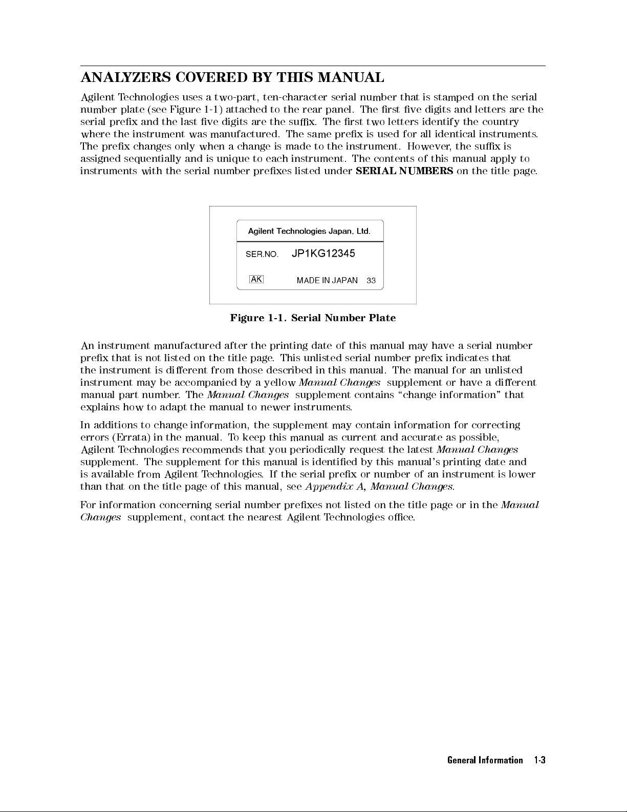
ANALYZERS
BY
THIS MANU
AL
Agilent
number
serial
where
The
assigned
T
echnologies
plate
prex
the
prex
sequentially
instruments
An
instrument
prex
the
that
instrument
instrument
manual
explains
part
how
(see
Figure
and
the
instrument
changes
with
only
the
manufactured
is
not
listed
is
dierent
may
be
accompanied
number
to
adapt
uses
1-1)
last ve
was
when a
and
serial
on
.
The
the
a two-part,
attached to
digits are
ten-character serial
the rear
the sux.
manufactured. The
is
unique to
change is
made to
each instrument.
number prexes
Figure
after
the
title
from
Manual
manual
the
page
those
by
a
Changes
to
1-1.
printing
.
This
described
yellow
newer
panel. The
The rst
same prex
the instrument.
listed under
Serial
Number
date
of
unlisted
in
this
Manual
supplement
instruments
number that
rst ve
two letters
is used
for all
However
The contents
SERIAL NUMBERS
Plate
this
manual
may
serial number
manual.
Changes
contains
The
supplement
\change
.
is stamped
digits and
identify the
on the
letters are
country
identical instruments
,
the
sux
of this
manual
on the
have
a
serial
prex indicates
manual
or
for
an
have
unlisted
information"
is
apply
title
number
that
a
dierent
that
serial
the
to
page
.
.
In
additions
errors
Agilent
supplement.
is
available
than that
For
information concerning
Changes
to
(Errata)
T
echnologies
The
from
on the
supplement,
change
in
the
supplement
Agilent
title page
information,
manual.
T
o
recommends
for
T
echnologies
of
this
serial number
contact the
the
supplement
keep
this manual
that
you
periodically
this
manual
.If
the serial
manual,
see
prexes
nearest Agilent
may
as current
is
identied
prex or
Appendix
not
Technologies
contain information
and
accurate
request
by this
the latest
manual's printing
number of
A,
listed
Manual
on
the
oce
Changes
title
.
for
correcting
as
possible
Manual Changes
date
an
instrument
.
page
or
in
the
,
and
is
lower
Manual
General Information 1-3
Page 28
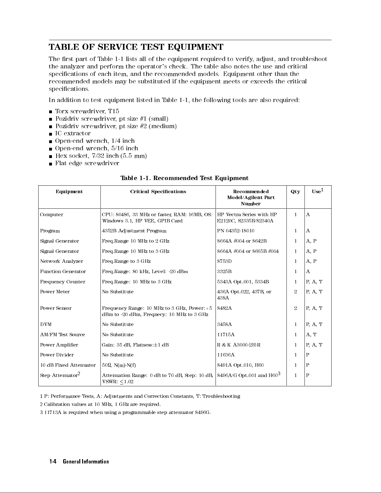
TABLE
The
rst
part
the
analyzer
specications
recommended
specications
In
addition
T
orx
P
ozidriv
P
ozidriv
to
screwdriver
screwdriver
screwdriver
IC extractor
Open-end
Open-end
Hex
socket,
Flat
edge
screwdriver
of
Table
and
perform
of
each
models
.
test
equipment listed
,
T15
wrench,
wrench,
7/32 inch
1-1 lists
the operator's
item,
and the
may
be
,
pt size
,
pt size
1/4 inch
5/16 inch
(5.5 mm)
T
able
TEST EQUIPMENT
all of
the equipment
check. The
required to
table also
recommended models
substituted if
in T
the equipment
able 1-1,
the following
#1 (small)
#2 (medium)
1-1.
Recommended
T
est Equipment
verify,
notes the
. Equipment
meets or
tools
are
adjust, and
use and
other than
exceeds the
also
required:
troubleshoot
critical
the
critical
Equipment Critical
Specications
Recommended
Model/Agilent
P
Qty Use
art
Number
Computer CPU:
Program 4352B
Signal
Generator
Signal
Generator
Network
Function
Analyzer
Generator
80486,
Windows
3.1,
Adjustment
Freq.Range
Freq.Range
Freq.Range
Freq.Range:
33
10
10
to
80
Frequency Counter Freq.Range: 10
P
ower
Meter
No
Substitute
HP
MHz
MHz
3
MHz
VEE,
GHz
kHz,
MHz
or
faster
GPIB
Program
to
2
GHz
to
3
GHz
Level:
to
3
-20 dBm
GHz
,
RAM:
Card
16MB
HP
V
ectra
Series
with
8642B
8665B
HP
#004
,
OS:
E2120C,
PN
8664A
8664A
82335B/82340A
04352-18010
#004
or
#004
or
8753D 1 A,
3325B 1 A
5343A Opt.001,
436A
Opt.022,
5334B
437B
,
or
1 A
1 A
1 A,
1 A,
1 P,
2 P
438A
P
ower Sensor
Frequency
dBm to
-20 dBm,
Range: 10
Freqnecy: 10
MHz
to
3
GHz,
MHz to
P
ower:+5
3
GHz
8482A 2 P
DVM No Substitute 3458A 1 P,
AM/FM
T
est
Source
No
Substitute
Power Amplier Gain: 35 dB
, Flatness:
6
1dB
11715A 1 A,
R & K A3000-2H-R 1 P,A,T
Power Divider No Substitute 11636A 1 P
10 dB Fixed
Attenuator
Step Attenuator
2
50, N(m)-N(f) 8491A Opt.010, H60 1 P
Attenuation Range: 0 dB to 70 dB
, Step: 10 dB
8496A/G Opt.001 and H60
,
3
1 P
VSWR:1.02
P
P
P
A,
,
A,
,A,
A, T
T
1
T
T
T
1
P: P
erformance T
2
Calibration values at 10 MHz, 1 GHz are required.
3
11713A is required when using a programmable step attenuator 8496G.
ests,A: A
djustments and Correction Constants
, T: Troubleshooting
1-4 General Information
Page 29
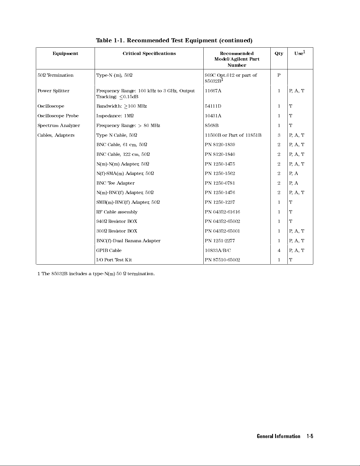
T
able 1-1.
Recommended T
est
Equipment
(continued)
Equipment Critical
Specications
Recommended
Model/Agilent P
art
Qty Use
Number
50 T
P
ower
ermination
Splitter
Type-N (m),
Frequency
Tracking:
Oscilloscope Bandwidth:
50
Range:
0.15dB
100
100
MHz
kHz
909C Opt.012
85032B
to
3
GHz,
Output
11667A 1 P
or part
1
of
54111D 1 T
P
Oscilloscope Probe Impedance: 1M 10431A 1 T
Spectrum
Cables,
Analyzer
A
dapters
Frequency
Type N
BNC
BNC
N(m)-N(m)
N(f)-SMA(m)
BNC
N(m)-BNC(f)
SMB(m)-BNC(f)
RF
940
300
Cable
Cable
T
ee
Cable
Resistor
Resistor
Range:
Cable
,
61
,
122
A
dapter
A
dapter
assembly
,
50
cm,
cm,
A
dapter
Adapter
A
dapter
BOX
BOX
BNC(f)-Dual Banana
GPIB
Cable
I/O
P
ort
T
est
Kit
>
80 MHz
50
50
,
50
,
,50
A
50
,
50
dapter
8568B 1 T
11500B or
PN
8120-1839
PN
8120-1840
PN
1250-1475
PN
1250-1562
PN
1250-0781
PN
1250-1476
PN
1250-1237
PN
04352-61616
PN
04352-65002
PN
04352-65001
P
art
of
11851B
3 P,
2 P
2 P
2 P
2 P
2 P
2 P
1 T
1 T
1 T
1 P
PN 1251-2277 1 P,
10833A/B/C 4 P
PN
87510-65002
1 T
,
A,
A,
,
A,
,
A,
,
A,
,
A
,
A
,A,
,
A,
A,
,
A, T
1
T
T
T
T
T
T
T
T
1
The
85032B
includes a
type-N(m) 50
termination.
General Information 1-5
Page 30

Page 31

P
erformance T
INTRODUCTION
This
chapter provides
information.
specications
These performance
.
information on
ests
tests are
the 4352B
used to
VCO/PLL
verify that
Signal
the
Analyzer
4352B
performance
performance
tests
meets
2
its
General
procedures
Each
information about
for each
test procedure
Description:
T
est
Equipment:
Procedure:
GENERAL
This
section
W
arm
Allow
performance
Ambient
P
erform
provides
Up
Time
the
4352B
Conditions
all
performance
tests
Calibration
the performance
test are
consists of
describes
describes test
describes
INFORMA
general
to
warm
up
.
tests
Cycle
provided.
the
following
the test
the
TION
information
for
at least
within
ambient conditions
tests
parts:
procedure
equipment
test
procedure
about
30 minutes
is
provided
.
required
the
performance tests
before
step
in
by
you
of 23
rst.
the
step
execute
6
Then,
test.
.
C,
5
step
.
any
70%RH.
of
by
step
the
The 4352B requires periodic
of performance verication depends on
which the 4352B is used. V
performance tests given in this chapter
Performance T
The P
erformance T
est Record
est Record lists
performance verication to remain in calibration. The frequency
the operating and environmental conditions under
erify the 4352B 's performance at least every two years using the
.
all test points
, acceptable test limits
, test result entry
columns, and measurement uncertainties. The measurement uncertainty shows how accurately
the 4352B's specications are measured and depends on the test equipment used. The listed
measurement uncertainties are valid only when the recommended test equipment is used.
The Performance Test Record is provided at the end of this chapter. Use the record as a master
and make extra copies for performance testing.
Performance Tests 2-1
Page 32

Recommended
T
able
1-1
lists
the
may
be
substituted
1-1.
T
est
Equipment
equipment
if
the
equipment
required
for
performance
meets or
testing
exceeds the
the 4352B
critical specications
.Other
equipment
given in
Table
2-2 Performance Tests
Page 33

FREQUENCY MEASUREMENT
Description
This
test
measures the
frequency
Specication
measurement
output frequency
accuracy
over
from the
its
entire
external signal
frequency measurement
generator,
and veries
range.
the
Frequency
Resolution
When
A
ccuracy
T
est
Equipment
Signal
Network Analyzer
N(m)-N(m)
BNC
cable;
GPIB
Procedure
1.
Connect
Range
@1kHz
:
:
Generator (SG#2)
cable
122
Cable
the
:
:
:
:
test
:
::
:
Selected
:
,
cm,
::
:
:
:
:
:
:
:
as
:
:
::
::
::
:
:
:
:
:
:
:
:
:
:
61
cm, 2
2ea.
::
::
:
:
:
:
:
equipment
::
::
::
resolution
:
:
:
6
(time
:
:
:
:
:
:
:
:
:
:
:
:
:
ea.
:
::
::
:
:
:
:
:
:
:
:
as
::
:
:
:
:
base
:
:
:
:
:
:
:
:
:
:
:
::
:
:
:
:
:
:
:
:
:
:
:
:
:
shown
:
:
:
:
:
:
:
:
:
:
:
:
:
:
:
:
:
:
:
:
:
::
::
in
:
:
:
:
:
:
:
:
:
:
::
::
::
accuracy
:
:
:
:
::
::
::
:
:
:
:
:
:
:
:
:
:
:
:
:
:
:
:
:
:
:
:
:
:
::
::
:
:
:
Figure 2-1
:
:
::
::
::
::
:
:
:
:
:
:
:
:
:
:
:
:
:
:
:
:
:
::
::
10 MHz
::
:
:
:
:
:
:
:
:
:
:
:
:
:
:
:
:
:
::
::
::
::
:
:
:
:
:
:
of
the
external
:
:
:
:
:
:
:
:
:
:
:
:
:
:
:
:
:
:
:
:
:
:
:
:
:
:
:
:
:
:
::
::
::
:
:
:
::
::
::
:
:
:
:
:
:
:
:
:
:
:
:
:
:
:
:
:
:
:
:
.
signal
source
:
:
:
:
:
:
:
:
::
::
:
:
:
:
:
:
:
:
:
:
:
:
:
::
:
:
:
:
:
:
:
:
:
:
:
:
:
:
:
:
:
:
:
:
:
:
:
11500B
:
:
:
:
:
:
:
:
:
:
:
:
::
::
::
::
:
:
or
:
::
::
::
:
:
:
:
:
:
:
:
:
:
:
to 3
:
:
:
:
:
:
:
:
:
1
used
+
1
:
8664A/8665B
:
:
:
:
:
:
:
:
:
8753D
part
of
11851B
:
PN
8120-1840
:
PN
8120-3445
GHz
kHz
kHz)
Note
Figure 2-1. Frequency Measurement Test Setup
Connect the signal generator's 10 MHz frequency reference output to the
4352B EXT REF Input on the rear panel as shown in Figure 2-1. With this
conguration, both the signal generator and the 4352B are phase locked to the
same reference frequency to obtain a stable measurement.
Performance Tests 2-3
Page 34

Note
2.
Press
Mode.
3.
Set
a.
b.
4.
Set
5.
Read
4352B
4
Meas
the
measurement
Press
4
Preset
Press
4
Sense
the
network
the
4352B
reading,
In
this
test,
oscillator
following
a.
Connect
b.
Press
N
N
N
N
N
NN
NN
NN
ADDRESS:
generator (SG#2).
address is
c.
Press
8664A.
d.
Press
indicator
N
N
N
N
N
N
N
N
N
N
N
N
N
N
N
N
N
N
5
,
INST
N
TYPE
5
,
4
Meas
5
,
Range
analyzer's
measurement
and
record
the
.
The
procedures
the
5
4
Lo
cal
NN
NN
NN
NN
N
N
N
N
N
N
N
N
N
19.)
4
RF/LO
4
Preset
is
N
N
N
NN
NN
N
N
N
N
INST
,
controls
5
,
and
N
N
N
N
N
N
NN
NN
NN
N
FREQ
N
N
N
the
NN
4352B
4352B
GPIB cable
N
N
N
SYSTEM
,
N
N
NN
NN
SG
5
,
5
to
lit.
N
N
N
N
N
N
N
N
N
N
N
N
FREQUENCY
N
N
N
N
N
N
RES:
output
uses
automatically
.
N
N
N
N
N
NN
NN
NN
NN
NN
N
and
the
(The
N
N
N
NN
NN
NN
NN
N
N
N
N
SG
TYPE
initialize
N
N
N
N
N
N
N
N
N
NN
NN
NN
N
TYPE:
as
follows:
N
N
N
NN
N
N
N
N
N
N
N
N
N
N
N
N
N
N
N
N
N
N
N
N
N
NN
NN
NN
1kHz
to
result.
calculated
the
signal generator
between the
NN
NN
N
N
N
N
N
N
N
N
N
N
N
NN
NN
NN
entry
factory
N
N
5
,
,
4
1
the
N
N
N
N
N
N
N
N
N
N
N
N
VCO
N
to
set
N
to
set the
MHz,
value
NN
keys
4
x1
4352B
NN
NN
NN
TESTER
CONTROLLER
N
N
N
N
N
N
N
N
N
N
N
N
N
N
N
N
N
N
N
N
N
N
N
N
10
Subtract
controls
NN
NN
NN
N
N
N
N
N
N
.
to
default
5
to set
.
N
N
N
N
N
N
N
N
N
N
N
N
N
the
measurement
frequency resolution
0
dBm.
the
network
in
the
SG#2
4352B and
Then
press
set the
setting
the signal
Conrm
N
N
to
set
the
performance
analyzer setting
(SG#2) as
via GPIB
the signal
N
N
N
N
SET
GPIB address
of
that
instrument
item
the rst
N
N
N
N
NN
NN
NN
NN
NN
NN
NN
ADDRESSES
the
signal
generator type
the
SG#2's GPIB
to
Frequency
to 1
test
record.
local
by performing
generator.
N
N
N
N
N
N
N
N
N
N
N
NN
NN
NN
NN
,
of the
type
signal
generator
to the
remote
to
the
.
kHz.
value from
the
T
ester
the
6.
Change
each
of
100
1
GHz
3
GHz
the
these
MHz
network
settings:
analyzer's
output
to
the
frequencies
listed
below
. Repeat
step
5
for
2-4 Performance Tests
Page 35

RF PO
Description
This
tests
measures the
and
veries
Specication
the
RF
output level
power
of the
measurement
ACCURA
signal generator
accuracy.
CY TEST
with/without the
power amplier
,
Frequency
Input
Resolution
A
T
est
Signal Generator
Power
Power
Power
Power
10
50
N(m)-N(m)
N(f)-SMA(m)
N(m)-N(m)
BNC
Procedure
Level
ccuracy
@
2GHz,
@Other
@P
eak
V
Equipment
Amplier (35
Meter
Sensor
Splitter
dB
Fixed
T
ermination,
cable
,
Range
:
:
:
:
:
:
:
:
:
:
:
:
:
15dBm,
than
the
oltage
Response
(SG#2)
,
2
ea.
,
2
ea.
:
:
:
Attenuator
adapter
adapter
cable
,
61
122
cm
:
:
:
:
:
:
:
::
:
::
::
::
::
:
::
::
::
::
P
eak
above
,
:
:
dB)
:
:
:
:
:
:
:
:
:
:
:
:
:
:
:
:
:
:
:
:
:
:
:
:
:
type-N(m)
,
50
:
:
,
2
ea.
cm,
2
:
:
:
:
:
:
:
:
P
,
:
:
:
:
:
:
:
::
:
:
:
ea.
::
:
:
:
:
:
:
V
oltage
eak
0
:
:
:
:
:
:
:
:
:
:
:
:
:
:
:
:
:
:
:
:
:
:
:
:
:
:
::
:
:
:
:
:
:
:
:
Voltage
to 40
:
:
:
:
:
:
:
:
:
:
:
:
:
:
:
:
:
:
:
:
:
:
:
:
:
:
:
:
:
:
:
:
:
:
:
:
:
:
:
:
:
::
:
:
:
:
:
:
:
:
:
:
:
:
:
:
:
:
:
Response
C
:
:
:
:
:
:
:
:
:
:
:
:
:
:
:
::
::
:
:
:
::
::
::
:
:
:
:
::
:
:
:
:
:
:
:
:
:
::
:
:
:
:
:
:
:
:
:
:
:
::
:
:
:
:
:
:
:
:
:
:
:
:
:
::
::
:
:
:
:
::
::
,
Response,
:
:
:
:
:
::
::
:
:
:
::
::
:
::
::
::
:
:
:
:
:
:
::
:
:
:
:
:
:
:
:
:
:
:
:
:
:
:
:
:
:
:
:
:
:
:
::
:
:
:
:
:
:
:
:
:
:
:
:
:
::
:
:
:
:
:
:
::
:
:
:
:
:
:
:
:
:
:
:
:
:
::
:
23
::
:
:
:
:
:
:
:
:
:
::
::
:
:
::
::
::
::
:
:
:
:
:
:
:
:
:
:
:
:
:
:
:
:
:
::
::
:
10
MHz to
::
:
:
:
:
:
:
:
:
:
:
:
:
:
:
:
:
:
::
::
::
0
10
dBm
::
:
:
:
:
:
:
:
:
:
:
:
:
:
:
:
:
:
::
::
::
::
:
:
:
:
:
:
:
:
:
C
:
:
:
:
:
:
:
:
:
:
:
:
:
:
:
:
::
::
::
::
:
:
:
:
:
:
:
:
:
:
:
:
:
:
:
:
:
:
::
::
::
:
:
:
:
:
:
:
:
:
:
:
:
:
:
:
:
:
:
:
::
::
::
:
:
:
:
:
:
:
:
:
:
:
:
:
:
:
:
:
::
::
::
:
:
:
:
:
:
:
:
:
:
8664A/8665B
:
:
:
:
:
::
::
::
::
:
:
:
:
R
&
K
::
::
:
:
:
:
:
:
:
:
:
:
:
:
:
:
:
:
:
:
:
:
:
::
::
:
:
:
:
:
:
:
:
:
:
:
:
:
:
:
:
:
:
:
::
:
:
:
:
:
:
:
:
:
:
:
:
:
:
:
:
:
:
:
:
:
::
:
::
:
:
:
:
:
:
:
:
:
:
:
:
:
:
:
:
:
:
:
:
:
:
:
909C
::
:
:
:
:
:
:
:
:
:
:
:
:
:
::
:
:
::
:
:
:
Opt.012
:
:
:
:
:
:
:
:
:
:
:
:
:
11500B
:
:
:
:
:
:
8491A
:
:
:
:
:
:
:
:
Opt.010,
or part
:
:
:
:
:
:
PN
:
:
:
:
:
PN
or
part
:
:
:
:
:
PN 8120-1840
6
10
23
::
:
:
:
:
:
:
:
:
:
:
:
:
:
:
:
:
:
:
:
:
:
:
:
:
:
:
:
:
:
:
:
:
:
:
:
:
:
:
:
:
:
:
:
:
:
C
6
10
:
:
:
:
:
:
:
:
:
:
:
:
:
:
:
:
:
:
:
:
:
:
:
:
:
:
:
:
:
:
:
:
:
:
:
:
:
:
:
:
:
:
:
:
:
:
:
:
:
::
:
:
:
:
:
:
:
:
:
:
:
:
:
:
:
:
:
:
:
:
:
:
:
:
:
:
:
:
:
:
:
:
:
:
:
:
:
:
:
:
:
:
:
:
:
:
:
::
3
GHz
to
+20
dBm
:
:
:
:
0.01
:
:
:
:
:
6
0.6dB
:
:
:
:
:
6
1.0dB
:
:
:
:
:
6
2.0dB
A3000-2H-R
:
::
::
:
:
436A
:
:
::
::
8482A
::
:
:
11667A
H60
of
85032B
1250-1475
1250-1562
of
11851B
dB
1.
Connect
the
sensor #B
Set the
2.
Obtain
procedures.
a. Connect the test
the
power
sensor
to the
power meter
the
tracking
power
sensor
#A.
power meter
#A
to
the
power meter
Set
the
power
#B's display
error
data
equipment as shown in Figure 2-2.
#B.
of
unit to
the
meter
Calibrate
dBm.
power
#A's display
the
power
splitter
#A. Calibrate
in accordance
unit to
meter
the power
dBm. Connect
#B
with
the
with
meter
power
the
Performance Tests 2-5
#A
the
power
sensor
following
with
#B
.
Page 36

b.
c.
Set
the
Set
the
and
record
(where
Figure
signal
output
,
XXX
generator
frequency
each
is
the
2-2.
power
SG's
P
ower
output
of
meter
setting
Splitter
level
the
signal
value
frequency).
Tracking
to
6
dBm.
generator
at
each
Error
in
accordance
frequency
Measurement
with
as
PMA1(XXX)
Setup
the
and
following
1
table
PMB1(XXX)
,
SG
Frequency
10
MHz
50
MHz
100
MHz
500
MHz
1
GHz
1.5
GHz
2
GHz
2.5
GHz
3GHz PMA1(3G) PMB1(3G)
d. Reverse the power sensor with
shown in Figure 2-3.
P
ower
V
alue
Meter
as:
#A
P
ower
V
alue
Meter
PMA1(10M) PMB1(10M)
PMA1(50M) PMB1(50M)
PMA1(100M) PMB1(100M)
PMA1(500M) PMB1(500M)
PMA1(1G) PMB1(1G)
PMA1(1.5G) PMB1(1.5G)
PMA1(2G) PMB1(2G)
PMA1(2.5G) PMB1(2.5G)
10 dB attenuator connections on the P
#B
as:
ower Splitter as
2-6 Performance Tests
Page 37

e.
Repeat
of
f.
Calculate
Figure
the
step
PMA1(XXX),
the
2-3.
c
except
PMB1(XXX),
following
P
ower
for
formula.
Splitter
the
Tracking
recording
respectively
Note
each
name
.
calculated
Error
.
Use
Measurement
PMA2(XXX),
value
as
Track(XXX).
Setup
2
PMB2(XXX)
instead
Track(XXX)=[
3.
Remove
with
the
a
N(m)-N(m)
f
PMA1(XXX)
50
termination,
adapter
as
and
shown
-
PMB1(XXX)
connect
in
Figure
the
g
-
2-4
power
f
PMA2(XXX)
splitter
.
-
PMB2(XXX)
to
the
4352B
g
RF
]
/
2
IN
connector
Performance Tests 2-7
Page 38

Figure
2-4.
RF
P
ower
Measurement
A
ccuracy
T
est
Setup
1
Note
4.
Press
5.
Press
Connect
4352B
conguration,
the
5
4
Preset
5
4
,
Meas
to
N
N
N
N
N
INST
EXT
same
initialize
N
N
NN
NN
NN
NN
N
N
N
N
N
TYPE
the
signal
REF
both
reference
the
N
N
N
N
N
N
N
N
N
N
N
N
N
N
N
INST
,
generator's
Input
on
the
frequency
4352B
.
N
NN
NN
NN
NN
N
N
N
N
N
N
N
N
TYPE:
the
signal
N
N
N
N
N
N
N
N
N
10
rear
generators
to
NN
NN
NN
NN
N
N
N
N
N
N
N
VCO
TESTER
MHz
frequency reference
panel
as
shown
and
the
obtain
N
N
N
a
stable
N
N
N
N
N
N
N
NN
NN
NN
NN
to
set the
output
in
Figure
4352B
are
2-4
phased
measurement.
instrument type
.
With
Mode.
NN
NN
NN
N
N
N
N
N
N
N
N
N
N
N
N
N
N
N
N
N
N
N
NN
NN
NN
N
N
N
N
N
N
N
N
N
N
N
N
6. Press
7.
Set the
MEAS: RF
signal generator
POWER
N
to
set
the
measurement
output frequency
to 10
item
to
MHz, and
RF
P
turn
ower
the
.
signal
generator
ON.
8. A
djust the signal generator output level around 6 dBm until the power meter reading is -10
dBm60.1 dB
9. Read the 4352B measurement result, and calculate
Test Result (dB) = 4352B reading - (P
Record the calculated test result on the P
.
the following formula:
ower Meter reading - Track(10M))
erformance T
est Record.
to
the
this
locked
to T
to
ester
output
2-8 Performance Tests
Page 39

10.
11.
12.
Set the
and
repeat step
10
MHz
50
MHz
100
500
1
GHz
1.5
2
GHz
2.5
3
GHz
Set the
output
Read
T
est
Result
signal generator
8and
MHz
MHz
GHz
GHz
signal
level
the
to
4352B
(dB)
generator
around
measurement
=
output frequency
step 9.
output
-4
dBm
4352B
-
(P
frequency
until
result,
ower
Meter
the
and
power
calculate
reading
in accordance
to
50
MHz,
and
meter
reading
the
-
Track(50M))
with the
adjust
is
following
following frequencies
the
signal
generator
-20
dBm
6
0.1
dB
formula:
,
.
Record the
13. Turn
Figure 2-5
the
calculated
signal
.
test
generator
result
output
on
OFF
the
,
P
and
erformance
connect
the
T
est
test
Record.
equipment
as
shown
in
Figure 2-5. RF P
ower Measurement A
ccuracy T
est Setup 2
14. Set the signal generator output level to -22 dBm, 50 MHz, and turn the signal generator
output ON. Adjust the signal generator output level until the power meter reading is 0 dBm
6
0.1 dB.
15. Read the 4352B measurement result, and calculate the following formula:
Performance Tests 2-9
Page 40

T
est Result
(dB) =
4352B
reading
-
(P
ower
Meter
reading
-
Track(50M))
Record
16.
Turn the
50
MHz. Then
17.
Adjust
18.
Read
T
est
Record
Caution
the calculated
signal
the
signal
the
4352B
Result
(dB)
the
calculated
T
o prevent
turn
test
generator
turn
the
signal
generator
measurement
=
4352B
test
damage
the power
result
output
generator
output
result,
reading
result
amplier
of
on
OFF
level
-
on
the
the
(P
the
P
,
and
and
ower
P
4352B
o
erformance
set
the
signal
output
until
the
ON.
power
calculate
Meter
reading
erformance
from
immediately
T
est
Record.
generator
meter
the
following
-
T
est
Record.
an
accidentially
after
output
reading
formula:
Track(50M))
large
this
test
is
level to
is
10dBm
signal
level
completed.
-12 dBm,
6
0.1 dB
input,
.
2-10 Performance Tests
Page 41

C/N RA
Description
This
test
veries the
uses
the
10
MHz
Specication
accuracy of
internal
reference
PHASE NOISE
the Carrier/Noise
frequency on
ratio measurement
the rear
panel as
TEST
in T
the carrier
ester Mode
frequency
. This
.
test
Phase
T
est
BNC
BNC(f)-N(m)
Procedure
1.
Connect
Noise
@1
kHz
@10
kHz
@100
kHz
Equipment
cable
Oset
Oset
,
122
the
:
:
:
:
:
:
:
Oset
:
:
cm,
2
adapter
test
equipment as
:
:
::
::
::
::
:
:
:
:
:
:
:
:
:
:
:
:
:
:
:
:
:
::
::
::
::
:
:
:
:
:
:
:
:
:
:
:
:
:
:
:
:
:
::
::
::
::
:
:
:
:
:
:
100
dBc/Hz
:
:
:
::
::
::
::
:
:
:
:
:
:
:
:
:
:
:
:
:
:
:
:
:
::
::
::
::
:
:
:
:
:
:
:
:
:
:
:
:
:
:
:
:
:
::
::
::
::
:
:
:
:
:
130
dBc/Hz
:
:
:
:
:
:
::
::
::
:
:
:
:
:
:
:
:
:
:
:
:
:
:
:
:
:
:
:
::
::
::
:
:
:
:
:
:
:
:
:
:
:
:
:
:
:
:
:
:
:
::
::
::
:
:
:
:
140
dBc/Hz
ea.
:
::
::
:
:
:
:
:
:
:
:
:
:
:
:
:
:
:
:
:
:
:
:
:
::
::
:
:
:
:
:
:
:
:
:
:
:
:
:
:
:
:
:
:
:
:
:
::
::
:
:
PN
8120-1840
,
2
ea.
:
:
:
:
:
:
:
:
::
:
:
:
:
:
:
:
:
:
:
:
:
:
:
:
:
:
:
:
:
:
:
:
::
:
:
:
:
:
:
:
:
:
:
:
:
:
:
:
:
:
:
:
:
:
PN
1250-1476
shown in
Figure
2-6
.
2. Press
3.
Press
Mode.
4. Press
5.
Press
4
Preset
4
Meas
4
Meas
4
Bw/Avg
Figure 2-6.
5
to initialize the 4352B .
NNNNNNNNNNNNNNNNNNNNNNNNNNNNN
5
,
INST TYPE
NNNNNNNNNNNNNNNNNNNNNNNNNNNNNNNNNNNNNNNNN
5
,
CARRIER/NOISE
NNNNNNNNNNNNNNNNNNNNNNNNNNNNNNNNNNNNNNNNNNNNNNNNNN
5
,
AVERAGING on OFF
NNNNNNNNNNNNNNNNNNNNNNNNNNNNNNNNNNNNNNNNNNNNNNNNNNNNNNNNNNNNNN
,
INST:TYPE VCO TESTER
C/N Measurement Phase Noise T
to set the instrument type to the Tester
to set the measurement item to Carrier/Noise ratio.
to turn the averaging function (AVG=16) ON.
est Setup
Performance Tests 2-11
Page 42

6.
Press
with
Record.
1
10
100
4
the
kHz
kHz
Bw/Avg
following
kHz
N
5
,
NN
NN
NN
NN
NN
NN
N
N
OFFSET
list,
N
N
N
N
N
N
N
N
N
N
N
FREQ
and
NN
NN
NN
NN
record
N
,
and the
entry keys
each
measurement result
to set
the oset
on the
frequency in
Performance
accordance
Test
2-12 Performance Tests
Page 43

C/N MEASUREMENT
Description
This
test
veries the
signal
generated
is
used
to
make
Specication
by
a
carrier
atness of
two
signal
signal, and
the Carrier/Noise
generators
is used
the other
ACCURA
ratio measurement
as the
is used
signal under
to make
CY TEST
in T
ester Mode
test (One
a
noise
signal).
signal
.The
generator
mixed
C/N
@1
@1
y
(Note
frequency
T
est
Equipment
Signal
Signal
Network
P
ower
P
ower
P
ower
dB
P
ower
Step
N(m)-N(m)
N(m)-N(m)
BNC
GPIB
Measurement
kHz
to
1
MHz
MHz
to
10
MHz
F
F
F
F
F
F
F
F
F
F
F
FF
NOISE
that
if
above
5
kHz.)
Generator
Generator
Analyzer
Meter
Sensor
Divider
Fixed
Splitter
Attenuator
cable,
Cable
adapter,
cable,
122 cm,
1:
Calibration
2:
11713A
:
:
::
:
:
:
:
:
:
Attenuator
:
:
:
:
:
::
::
:
is
A
ccuracy
oset
oset
FF
FF
F
F
F
F
F
F
F
F
PLL
for
LO
(SG#2)
:
:
:
::
:
:
:
:
::
:
:
:
:
::
:
:
:
:
:
::
:
:
:
:
:
50, 2
61 cm,
3
ea.
:
:
:
:
:
values
required
F
F
F
F
F
auto
:
:
:
:
:
:
:
:
:
:
,
:
:
:
:
:
:
F
:
:
:
:
:
:
F
F
F
F
F
FF
FF
FF
F
WIDE
(SG#1)
:
:
:
:
:
:
:
:
:
:
:
:
:
:
:
:
:
:
:
:
:
:
:
:
:
2
ea.
:
:
:
:
:
:
:
:
:
:
ea.
3
ea.
:
:
:
:
:
:
:
:
for
attenuation
when
y
:
:
:
:
:
F
::
:
:
F
:
:
:
:
:
:
F
F
F
:
:
:
::
:
:
:
:
:
:
:
:
:
:
:
:
:
:
:
:
:
:
using
:
::
:
:
(
CNPLL
:
:
:
:
::
:
:
:
:
:
:
:
:
:
:
:
::
:
:
:
:
:
:
:
:
:
:
:
:
:
:
:
:
::
::
::
:
:
:
:
:
:
:
:
:
::
::
:
:
::
:
:
:
:
:
:
:
:
:
:
:
:
:
a
::
:
:
:
:
:
:
:
:
:
::
:
:
:
:
:
:
:
WIDE
)
is
selected, this
::
::
::
::
:
:
:
:
:
:
:
:
:
:
:
:
:
:
:
:
:
:
:
:
:
:
:
::
::
:
:
:
:
:
:
:
:
:
::
:
:
:
:
:
:
:
:
:
::
:
:
:
:
:
:
:
:
:
:
:
:
:
:
:
:
:
:
:
:
:
:
::
:
:
:
:
::
:
:
:
:
:
:
:
:
:
:
:
:
:
:
:
:
:
:
:
:
:
:
:
:
:
:
:
:
:
:
:
:
:
::
::
::
::
:
:
:
:
:
:
setting
of
40
programmable
:
:
:
:
:
:
:
:
:
:
::
::
::
:
:
:
:
:
:
:
:
:
:
:
:
:
:
:
:
:
:
:
::
::
::
:
:
:
6
2dB
:
:
:
:
:
:
:
:
:
:
:
:
::
::
::
:
:
:
:
:
:
:
:
:
:
:
:
:
:
:
:
:
:
:
::
::
::
:
6
4dB
accuracy is
:
:
:
:
:
:
:
:
:
:
:
:
:
:
:
:
:
:
:
:
:
:
:
:
:
:
::
:
:
:
:
:
:
:
::
::
:
:
:
:
:
:
:
:
:
:
:
:
:
:
:
:
:
:
:
:
:
:
:
:
:
:
:
:
:
:
:
:
:
:
:
:
:
:
:
:
:
:
:
:
:
:
:
:
:
:
:
:
:
:
:
:
::
:
:
:
:
:
:
:
:
:
:
:
:
:
:
:
:
:
:
:
:
:
:
:
:
:
:
:
:
:
:
:
:
:
:
:
:
::
::
:
:
:
:
:
:
:
:
:
::
::
:
:
:
:
:
:
:
:
:
:
:
:
:
:
:
:
:
:
:
:
:
:
:
:
:
:
:
:
:
:
:
:
::
::
dB
at
10
MHz,
step
attenuator
::
:
:
::
:
:
:
:
:
:
:
:
:
:
:
:
:
:
:
:
:
:
:
::
1
::
::
:
:
:
:
:
:
:
:
::
::
:
:
:
:
:
:
:
:
:
:
:
:
:
:
:
:
::
:
:
:
:
:
:
:
:
:
:
:
:
:
::
:
:
GHz
8496G.
valid at
::
:
:
:
:
:
:
:
:
:
:
:
:
::
:
:
::
:
:
:
:
:
:
:
:
::
:
:
:
:
:
:
:
:
:
:
:
11500B
:
:
::
:
:
:
:
are
required.
an
oset
:
:
:
:
:
:
:
:
:
:
:
:
8664A/8642B
:
:
:
:
:
:
:
:
:
:
:
:
8664A/8665B
:
:
:
:
:
:
:
:
::
::
:
:
:
:
:
:
:
:
8753D
:
:
:
:
:
:
:
:
:
:
:
:
:
:
:
:
:
:
::
:
436A
:
:
:
:
:
:
:
:
:
:
:
:
:
:
:
:
:
:
:
:
8482A
:
:
:
:
:
:
:
:
:
:
:
:
:
:
:
:
:
:
11636A
:
:
:
:
:
:
:
::
:
:
:
:
:
:
:
:
:
:
8491A
:
:
:
:
:
:
:
::
:
:
:
:
:
:
Opt.010,
:
:
:
:
:
:
:
:
:
8496A/G
::
:
:
:
PN
or
part
:
:
:
:
:
PN
:
:
:
:
:
PN 8120-3445
H60
:
:
:
:
11667A
Opt.H60
1250-1475
of
11851B
8120-1840
Procedure
1. Connect the
sensor.Set
2. Connect the test
the display unit to dBm.
power sensor to the power meter
equipment as shown in Figure 2-7.
. Calibrate the power meter with the power
Performance Tests 2-13
Page 44

Figure
2-7.
C/N
Ratio
Measurement
A
ccuracy
(Flatness)
T
est
Setup
Note
Note
3. Press
4.
Press
Mode.
5. Press
Connect
4352B
conguration,
same
In
oscillator
following
a.
b.
d. Press
4
5
Preset
4
5
,
Meas
4
5
,
Meas
the
signal
EXT
reference
this
test,
.
REF
the
The
generator's
Input
both
the
frequency
4352B
4352B
on
signal
uses
automatically
the
rear
generators
to
obtain
the
10
MHz
signal
frequency
panel
a
stable
generator
controls
as
shown
and
the
measurement.
(SG#1)
SG#1
reference
in
Figure 2-8
4352B
are
as
via
GPIB
output
phase
the
rst
by
performing
.
With
procedures.
Connect
Press
N
NN
N
N
N
N
ADDRESS: SG
the
GPIB
cable
N
NN
NN
N
N
N
N
N
N
N
N
SYSTEM
5
4
,
Lo
cal
N
N
N
N
N
N
NN
N
N
N
N
N
N
N
N
N
N
N
NN
N
N
N
N
N
N
N
between
N
N
N
N
N
N
N
N
N
NN
NN
NN
NN
N
CONTROLLER
N
N
N
N
N
the
N
NN
NN
NN
.
Then press
4352B
N
N
N
N
N
N
N
N
N
N
and
the
N
NN
NN
SET
N
N
N
N
N
N
signal
N
N
N
N
N
N
N
N
N
N
NN
NN
generator
NN
NN
N
N
N
ADDRESSES
N
N
N
N
and the entry keys to set the GPIB address of the signal
generator (SG#1). (The factory default setting of the signal generator
address is 19.)
c.
Press
4
RF/LO
NNNN
NNNNNNNNNNNNNNNNNNN
SG TYPE
5
,
5
to set the signal generator type to the
5,4
,
4
x1
1
8664A.
5
4
to initialize the 4352B
Preset
. Conrm that the SG#1's GPIB remote
indicator is lit.
to initialize the 4352B.
NNNNNNNNNNNNNNNNNNNNNNNNNNNNN
INST TYPE
NNNNNNNNNNNNNNNNNNNNNNNNNNNNNNNNNNNNNNNNNNNNNNNNNNNNNNNNNNNNNNNNN
,
INST TYPE: VCO TESTER
to set the instrument type to Tester
NNNNNNNNNNNNNNNNNNNNNNNNNNNNNNNNNNNNNNNNN
CARRIER/NOISE
to set the measurement item to Carrier/Noise ratio.
to
locked
local
N
N
N
N
N
,
the
this
to the
the
.
2-14 Performance Tests
Page 45

6.
Set the
4352B Measurement
Controls as
follows:
Control
RF
ATTEN
A
VERA
C/N
7. Set
8. Set
9. Turn
10. A
djust the
Then record
11. Turn
12.
Set
13.
A
djust the
Then
14.
Set
15. Turn
16.
Press
Carrier/Noise
Settings K
=0
dB
GING:
APERTURE:
SG#2's output
SG#3's output
the SG#2
the SG#2
the
step
record
the
step
both SG#2
4
Bw/Avg
ON
(A
MANU
signal
output
output
amplitude
the power
signal
attenuator
amplitude
the
power
attenuator
and
N
N
N
N
N
N
N
N
N
OFFSET
5
,
ratio
VG=16)
frequency to
frequency to
SG#3
N
NN
NN
N
measurement
AL
output
meter
output
to
meter
to
N
N
N
N
N
N
N
N
N
N
N
N
FREQ
ON,
of
OFF
0
dB
of
40 dB
signal
N
N
N
N
N
N
N
N
,
eystrokes
4
Sense Range
4
Bw/Avg
4
System
N
N
N
N
N
N
N
N
N
N
N
N
NN
C/N
APER
10 MHz
9MHz
and
SG#2
reading
,
and
.
SG#3
reading
.
outputs
5
,
4
4
M/
1
to
1
NN
NN
NN
NN
RF ATTEN
5
,
NN
NN
N
N
N
N
N
N
N
N
N
N
N
AVERAGING on
5
,
N
N
N
N
N
N
N
N
N
N
N
NN
NN
NN
SERVICE
5
,
NN
NN
NN
N
N
N
N
N
N
N
N
N
N
N
N
N
N
N
N
N
AUTO
as
the
as
the
noise
turn
the
until
the
as
turn
until
as PM
5
MHz.
carrier(10M).
PM
the
the
noise
ON.
to
set
NN
NN
N
N
N
N
N
N
NN
NN
NN
NN
NN
NN
NN
NN
NN
NN
N
N
N
MENU
NN
NN
NN
NN
N
N
N
N
man
carrier
SG#3
power
SG#3
power
the
oset
N
N
N
N
N
NN
N
,
NN
N
N
N
N
N
N
N
N
N
N
N
N
N
N
N
N
NN
,
N
N
N
N
signal.
signal.
signal
meter
signal
meter
(9M).
5
,
5
4
4
0
x1
N
N
N
NN
NN
NN
NN
NN
OFF
N
N
N
N
N
N
N
N
N
N
N
NN
NN
SERVICE
output
reading
output
reading
frequency
NN
NN
NN
NN
NN
N
N
N
N
MODES
OFF
to
of the
N
N
N
is
is
N
N
N
N
NN
.
-10
ON.
-10
NN
N
,
N
N
N
N
N
N
N
N
N
N
N
MISC
dBm
dBm
4352B
NN
NN
6
6
NN
NN
NN
NN
MENU
0.1
0.1
NN
N
N
N
N
,
dB
.
dB
.
17. Read
T
est Result(dB)
Step
Record
18.
Change
frequency
setting.
the
Att.)
the
the
4352B
test
signal
in
accordance
measurement
=
4352B
result
generator's
reading
on
the
with
SG#2
(Carrier)
10
10 MHz 9.999 MHz 1 kHz
10 MHz 10.001 MHz 1 kHz
10 MHz 11 MHz 1MHz
result,
P
erformance
(SG#2/SG#3)
the
Freq.
MHz
1 GHz 0.99 GHz 10 MHz
1 GHz 0.999 GHz 1MHz
1 GHz 0.999999 GHz 1 kHz
1 GHz 1.000001 GHz 1 kHz
and
-
(PM
following
SG#3
calculate
carrier(10M)
T
est
Record.
output
table
.
Freq.
(Noise)
the
following
noise(9M)
-PM
frequencies
Repeat
9
step
Oset
MHz
formula:
,
and
7
through
4352B
+40
the
Freq.
1
MHz
dB
4352B
step
Cal.V
oset
17
alue
for
of
each
1 GHz 1.001 GHz 1MHz
1 GHz 1.01 GHz 10 MHz
Performance Tests 2-15
Page 46

C/N RA
Description
This
test
veries the
mixed
generator
Specication
signal
is
generated
used
linearity of
by
to
make
the Carrier/Noise
two
signal
a
carrier signal,
LINEARITY A
ratio measurement
generators is
and the
used as
other is
CCURACY
the signal
used to
make
in T
ester Mode
under test
a
noise
TEST
.The
(One
signal
signal).
C/N
@1
@1
y
(Note
frequency
T
est
Equipment
Signal
Signal
Network
P
ower
P
ower
P
ower
10
dB
P
ower
Step
N(m)-N(m)
N(m)-N(m)
BNC
GPIB
Measurement
kHz
to
1
MHz
MHz
to
10
MHz
F
F
F
F
F
F
F
F
F
F
F
FF
NOISE
that
if
above
5
kHz.)
Generator
Generator
Analyzer
Meter
Sensor
Divider
Fixed
Splitter
Attenuator
cable,
Cable
adapter,
cable,
122 cm,
1:
Calibration
2:
11713A
:
:
::
:
:
:
:
:
:
Attenuator
:
:
:
:
::
::
is
A
ccuracy
oset
FF
FF
F
F
F
F
F
F
F
F
PLL
for
LO
(SG#2)
:
:
:
::
:
:
:
:
::
:
:
:
::
:
:
:
:
:
::
:
:
:
:
:
:
50, 2
61 cm,
3
:
:
:
:
:
:
values
required
oset
F
F
F
F
F
F
F
F
F
F
auto
(SG#1)
:
:
:
:
:
:
:
:
:
:
:
:
:
:
:
:
:
:
:
,
2
:
:
:
:
:
:
:
:
3
ea.
:
:
:
:
for
y
:
:
:
:
:
:
:
:
:
:
F
FF
FF
FF
F
F
F
F
F
F
WIDE
:
:
:
:
:
:
:
:
:
:
::
:
:
:
:
:
:
:
:
:
:
:
:
:
:
:
:
:
ea.
:
:
:
:
:
:
:
:
:
:
:
:
:
ea.
:
ea.
:
:
:
:
:
:
:
:
:
:
:
:
:
attenuation
when
using
:
::
:
:
(
CNPLL
:
:
:
:
::
:
:
:
:
:
:
:
:
:
::
:
:
:
:
:
:
:
:
:
:
:
::
::
:
::
:
:
:
::
:
:
:
:
:
:
:
:
:
:
:
:
:
:
:
:
:
:
:
:
::
::
:
:
:
:
:
:
::
::
:
:
:
:
WIDE
)
is
:
::
::
::
::
::
:
:
:
:
:
:
:
:
:
:
:
:
:
:
:
:
:
:
::
::
:
:
:
:
:
:
:
:
::
:
:
:
:
:
:
:
:
::
:
:
:
:
:
:
:
:
:
:
:
:
:
:
:
:
:
:
:
:
:
:
::
:
:
:
:
:
:
:
:
:
:
:
:
:
:
:
:
:
:
:
:
:
:
:
:
:
:
:
:
:
:
::
::
:
:
:
:
settings
a
programmable
:
:
:
:
:
:
:
:
:
:
:
:
:
:
:
:
selected, this
:
:
:
:
:
:
:
:
:
:
:
:
:
:
:
:
:
:
:
:
:
:
:
:
:
:
:
:
:
:
:
:
:
:
:
:
:
:
:
:
:
:
:
:
:
:
:
:
:
:
:
:
:
:
:
::
:
:
:
:
:
:
:
:
:
:
:
:
:
:
:
:
:
:
:
:
::
:
:
:
:
:
::
::
::
::
:
:
:
:
:
:
:
:
:
:
:
:
of
10
dB
step
:
:
:
:
:
::
:
:
:
:
:
:
:
:
:
:
:
:
:
:
:
:
:
:
:
::
::
:
:
:
:
:
:
:
:
:
:
:
:
:
:
:
:
:
:
:
:
:
::
:
:
:
:
:
:
:
:
:
:
:
::
:
:
:
:
:
:
:
:
:
:
:
:
:
:
:
:
:
:
:
through
attenuator
::
::
:
:
:
:
::
::
::
:
accuracy is
:
:
:
::
::
:
::
::
:
:
:
:
:
:
:
:
:
:
:
:
:
:
:
:
:
::
:
:
:
:
:
:
:
:
:
:
:
:
:
:
:
:
:
:
:
:
:
:
:
:
:
:
:
:
:
:
:
:
:
:
:
:
::
:
:
:
:
:
:
:
:
:
:
:
:
:
:
:
:
:
:
:
:
:
:
:
::
::
::
::
70
dB
at
8496G.
:
:
:
:
valid at
::
::
:
:
:
:
:
:
::
:
:
::
:
:
::
:
:
:
:
:
:
:
:
:
:
:
:
:
:
:
:
:
:
:
1
:
:
:
:
:
:
:
:
:
:
:
:
:
:
:
:
:
:
:
:
:
:
:
:
:
:
:
:
:
:
:
:
:
:
:
:
::
:
:
:
:
:
:
:
:
:
:
:
11500B
:
::
::
:
:
:
:
GHz
:
:
:
:
:
:
:
:
:
:
:
:
are
:
:
:
:
:
:
:
:
:
:
:
:
:
:
:
:
:
:
:
:
:
:
oset
:
:
:
:
:
:
:
:
:
:
:
:
:
:
:
:
:
:
:
:
:
:
:
:
:
8491A
:
:
:
:
:
:
:
:
:
::
::
:
:
:
:
:
:
:
:
required.
:
:
:
:
::
::
::
:
:
:
:
:
:
::
::
:
:
:
:
:
8664A/8642B
:
:
:
:
8664A/8665B
::
::
:
:
:
:
:
:
:
:
:
:
:
:
:
:
:
:
:
:
:
:
:
:
:
:
:
:
:
:
:
:
Opt.010,
:
:
:
:
:
:
:
:
:
8496A/G
:
:
:
PN
or
part
:
:
:
:
PN
8120-1840
:
:
:
:
PN 8120-3445
:
:
:
6
2dB
::
:
6
4dB
:
:
:
:
8753D
:
:
::
:
436A
:
:
:
8482A
:
:
11636A
H60
:
:
11667A
Opt.H60
1250-1475
of
11851B
Procedure
1. Connect the
sensor. Set
2. Connect the test
2-16 Performance Tests
power sensor to the power meter
the display unit to dBm.
. Calibrate the power meter with the power
equipment as shown in Figure 2-8.
Page 47

Figure
2-8.
C/N
Ratio
Measurement
A
ccuracy
(Linearity)
T
est
Setup
Note
Note
3. Press
4.
Press
Mode.
5. Press
Connect
4352B
conguration,
same
In
oscillator
following
d. Press
4
5
Preset
4
5
,
Meas
4
5
,
Meas
the
EXT
reference
this
test,
.
signal
REF
the
The
generator's
Input
both
the
frequency
4352B
4352B
10
on
the
rear
signal
generators
to
obtain
uses
the
signal
automatically
MHz
panel
a
stable
generator
controls
frequency
as
shown
and
the
measurement.
SG#1
reference
in
Figure 2-8
4352B
(SG#1)
via
GPIB
as
are
output
phase
the
rst
by
performing
.
procedures.
a.
Connect
b.
Press
N
NN
N
N
N
ADDRESS: SG
the
GPIB
cable
N
NN
NN
N
N
N
N
N
N
N
N
SYSTEM
5
4
,
Lo
cal
N
N
N
N
N
N
N
NN
N
N
N
N
N
N
N
N
N
N
N
NN
N
N
N
N
N
N
N
between
N
N
N
N
N
N
N
N
N
NN
NN
NN
NN
CONTROLLER
N
N
N
N
N
N
the
N
NN
NN
NN
.
4352B
Then press
N
N
N
N
N
N
N
N
N
N
and
the
N
NN
NN
SET
N
N
N
N
N
signal
N
N
N
N
N
N
N
N
N
NN
NN
NN
generator
NN
N
N
N
N
ADDRESSES
N
N
N
N
and the entry keys to set the GPIB address of the signal
generator (SG#1). (The factory default setting of the signal generator
address is 19.)
c.
Press
4
RF/LO
NNNN
NNNNNNNNNNNNNNNNNNN
SG TYPE
5
,
5
to set the signal generator type to the
5,4
,
4
x1
1
8664A.
5
4
to initialize the 4352B
Preset
. Conrm that the SG#1's GPIB remote
indicator is lit.
to initialize the 4352B.
NNNNNNNNNNNNNNNNNNNNNNNNNNNNN
INST TYPE
NNNNNNNNNNNNNNNNNNNNNNNNNNNNNNNNNNNNNNNNNNNNNNNNNNNNNNNNNNNNNNNNN
,
INST TYPE: VCO TESTER
to set the instrument type to Tester
NNNNNNNNNNNNNNNNNNNNNNNNNNNNNNNNNNNNNNNNN
CARRIER/NOISE
to set the measurement item to Carrier/Noise ratio.
to
With
locked
local
N
N
N
N
N
N
,
the
this
to the
the
.
Performance Tests 2-17
Page 48

6.
Set the
4352B Measurement
Controls as
follows:
Control
RF
A
VERA
NOISE
C/N
7.
Set SG#2's
8.
Set SG#3's
9.
Turn the
10.
Adjust
Then
11.
Turn
12.
Set
13.
Adjust
Then record
14. Turn
15.
Press
Carrier/Noise
16.
Read
Settings K
ATTEN
APERTURE:
the
=0
GING:
A
the
record
the
the
both SG#2
4
Bw/Avg
the
TTEN
output
output
SG#2
output
SG#2
step
output
4352B
ON
the
attenuator
the
5
,
ratio
dB
(A
VG=16)
=
30
dB
MANU
frequency
frequency
signal
amplitude
power
signal
amplitude
power
and
N
N
N
N
N
N
N
N
NN
NN
N
N
N
OFFSET
measurement
measurement
AL
output
meter
output
to
meter
SG#3
N
N
N
N
N
N
N
N
N
N
N
FREQ
0
dB
signal
N
N
N
N
N
N
N
NN
eystrokes
4
Sense Range
4
Bw/Avg
4
Sense Range
4
System
to
1.0001
to
1.0000
ON,
and
of
SG#2
reading
OFF
,
.
of
SG#3
reading
outputs
5
,
,
4
1
to
result,
and
5
4
0
100
NN
NN
NN
RF ATTEN
5
,
NN
NN
N
N
N
N
N
N
N
N
N
N
AVERAGING on
5
,
N
N
N
N
N
N
NOISE
5
,
N
N
N
N
N
N
N
NN
NN
NN
NN
N
SERVICE
5
,
GHz
as
GHz
as
turn
the
until
the
PM
the
the
PM
ON.
5
,
4
k/m
kHz.
calculate
carrier
noise (0dB).
5
as
turn
until
as
,
4
and
0
NN
NN
NN
N
N
N
N
NN
NN
NN
NN
N
N
N
N
N
NN
NN
N
N
N
N
N
N
N
N
N
MENU
the
the
SG#3
power
SG#3
power
to
N
N
N
N
N
N
N
N
NN
NN
NN
NN
N
N
N
N
NN
NN
NN
NN
NN
ATTEN
N
N
N
N
N
N
N
NN
NN
carrier
noise
signal
.
signal
set
the
the
N
5
,
,
N
N
N
N
N
N
N
N
NN
,
meter
meter
5
4
4
0
x1
N
N
N
NN
NN
NN
NN
NN
OFF
N
N
N
N
N
N
5
5
,
4
,
4
3
N
N
MISC
signal.
following
0
N
N
N
N
N
NN
NN
NN
NN
N
N
N
N
N
N
N
MENU
signal.
output
reading
output
reading
oset frequency
5
,
4
x1
N
N
N
N
N
N
N
N
N
N
N
OFF
to
N
,
is
is
C/N
.
-10
ON.
-
N
20
N
formula:
NN
NN
NN
dBm
of the
NN
N
N
N
N
N
N
APER
dBm
N
N
N
N
N
N
N
N
N
N
N
NN
AUTO
6
0.1
6
0.1
4352B
NN
NN
NN
N
N
N
N
N
N
N
N
N
N
N
N
N
man
dB
.
dB
.
17.
T
Record
Change
with
P
T
V
est
Result(dB)
the
the
the
following
erformance
est
Result(dB)
alue
of
Step
=
4352B
test
result
step
attenuator
list.
T
est
Record.
=
4352B
Attenuator)
reading
on
the
Calculate
reading
Attenuator
Setting
10
20 dB 10 dB 30 dB
30 dB 0dB 40 dB
40 dB 0dB 50 dB
50 dB 0dB 60 dB
60 dB 0dB 70 dB
70 dB 0dB 80 dB
-
P
erformance
setting
- (PM
dB
carrier
(PM
and
the
the
following
carrier
4352B
A
TTEN Setting
T
est
4352B
20
-
PM
Record.
Noise
formula,
-
PM
NOISE
dB
noise(0dB))
Attenuator
and
noise(each
record
attenuator)
C/N
ratio
20
dB
setting
each
in
accordance
test
result
+
Calibrated
on
the
2-18 Performance Tests
Page 49

FM DEVIA
Description
This
test
veries the
from
function
Specication
generator
accuracy of
with
an
the FM
AM/FM
deviation measurement.
Test
Source.
This test
uses the
FM signal
Measurement
Deviation
Deviation
@1kHz
@1kHz
@1kHz
@1kHz
T
est
Equipment
Signal
Function
AM/FM
N(m)-N(m) cable
BNC cable;
N(m)-BNC(f) adapter
GPIB Cable
Procedure
1.
Connect
Resolution
A
ccuracy
FM,
2kHz
FM,
2kHz
FM,
20,
FM,
20,
Generator
Generator
T
est
Source
122
:
:
:
the test
Range
cm,
:
:
range
range
200
kHz
200
kHz
for
LO
:
:
::
:
:
::
,
61
cm.
5
ea.
.
:
:
:
:
:
:
:
equipment as
:
:
:
:
:
:
,
,
(SG#1)
::
::
:
:
:
:
:
:
:
:
:
:
:
:
:
:
23
0
range
range
::
::
:
:
:
:
:
:
:
:
:
:
:
:
:
:
:
:
::
:
6
to
:
:
:
:
::
::
10
:
:
:
:
:
:
:
:
:
:
:
:
:
::
::
::
::
C
40
,
23
,
0to
::
::
:
:
:
:
:
:
:
:
:
:
:
:
:
:
:
:
:
:
:
::
shown
:
:
:
:
:
:
:
:
:
:
:
:
:
:
:
:
:
::
::
::
::
:
:
:
:
:
:
:
:
:
:
:
:
:
:
:
:
:
::
::
::
0to
200
kHz
::
:
:
:
:
:
:
:
:
:
:
:
:
:
:
:
:
:
::
::
::
::
:
:
:
:
:
:
:
:
:
:
:
:
:
:
:
:
:
::
::
::
::
:
:
4
digits
:
:
:
:
:
:
:
:
:
:
::
::
::
:
:
:
(
6
2%
of
reading
C
:
:
:
:
:
:
:
:
:
:
::
::
::
:
:
(
6
8%
of
C
:
:
:
:
:
:
:
:
6
10
C
:
40
:
:
:
:
:
:
:
:
:
:
:
:
:
:
:
:
:
:
:
:
:
:
:
:
:
:
:
:
:
:
:
:
:
:
:
:
:
:
::
:
:
:
:
:
:
:
:
::
:
:
:
:
:
:
:
:
:
::
:
:
:
:
:
:
:
:
:
in
Figure
:
:
::
(
6
2% of
:
:
:
:
:
::
::
:
(
6
8%
:
:
:
:
:
:
:
:
:
:
::
::
:
::
::
::
::
:
:
:
:
:
::
::
:
:
:
:
:
:
:
:
::
:
:
:
:
:
:
:
:
:
:
:
::
:
:
:
:
:
:
:
:
:
:
:
:
:
:
:
:
:
:
:
:
:
:
:
:
:
:
:
:
:
:
:
:
:
:
:
:
:
:
:
2-9
.
reading
reading
of
reading
::
:
:
:
:
:
:
:
:
:
:
:
:
:
:
:
:
:
:
:
:
:
:
:
:
:
:
:
:
:
:
:
:
:
:
:
:
:
:
:
:
:
:
:
:
:
:
:
:
:
:
:
:
::
:
:
:
:
:
:
:
:
:
:
:
:
:
:
:
:
::
:
:
:
:
::
:
::
11500B or
::
::
:
:
::
:
:
:
:
:
:
:
+
0.5%
of
meas
.range)
+
2.0%
of
meas
.range)
+
0.1%
of
meas
.range)
+
0.4%
of
meas
.range)
:
:
:
:
:
:
:
::
::
8664A/8642B
::
::
::
:
:
:
:
:
:
:
:
:
:
:
3325A
::
:
:
:
:
:
:
:
:
:
:
:
:
:
:
11715A
part
of
11851B
:
:
:
:
:
:
:
:
:
:
PN
8120-1840
:
:
:
:
:
:
:
:
:
:
PN
1250-1476
:
:
:
:
:
:
:
:
:
:
PN
8120-3445
Figure 2-9. FM Deviation Accuracy Test Setup 1
Performance Tests 2-19
Page 50

Note
Note
2.
Set
3.
Set
the
the
Connect
4352B
Input
signal
same
In
4352B
following
a.
b.
c.
d.
Test
Mode of
function
the
signal
EXT
REF
Input
on
the
rear
panel
generator
reference
this
test,
automatically controls
Connect the
Press
4
N
NN
NN
N
N
N
N
N
N
N
N
N
N
N
ADDRESS:
generator
Press
4
8664A.
Press
4
remote
AM/FM T
generator's
,
the
frequency
the 4352B
procedures.
GPIB cable
N
N
N
N
NN
NN
SYSTEM
5
,
Lo
cal
N
N
N
N
N
N
N
NN
NN
NN
NN
N
N
N
N
SG
and
.
(The
N
N
N
N
N
SG
5
,
RF/LO
5
to initialize
Preset
indicator
est Source
output to
generator's
on
the
as
shown
function
to obtain
uses the
NN
NN
N
factory
N
N
N
N
N
is
between the
N
N
N
N
N
N
N
N
N
N
N
N
N
N
N
N
NN
CONTROLLER
the
entry
default
N
N
N
N
N
N
N
N
NN
NN
N
TYPE
,
4
the 4352B
lit.
1 kHz.
NN
10
MHz
frequency
rear
panel and
in Figure
generator
signal generator
the signal
NN
NN
N
N
N
N
N
keys
5
,
4
x1
1
to
FM.
N
N
N
N
N
N
N
N
setting
5
to
,
a stable
N
N
N
. Then
to
set
.
Conrm
reference output
the function
2-8.
With this
and the
generator via
4352B
set
of
the
4352B are
measurement.
as the
and
N
N
SET
press
the
GPIB
the
signal
signal
that
generator EXT
conguration, the
phase locked
rst
local
GPIB
by
performing
the
signal
N
N
NN
NN
NN
NN
address
generator address
generator
the
generator
N
N
N
N
N
N
N
N
N
N
N
N
N
N
N
N
N
NN
ADDRESSES
signal
NN
of
type
generator's
to both
oscillator
NN
NN
N
N
N
N
,
the
signal
to
the
to the
.
the
REF
.
The
the
is 19.)
GPIB
4.
5.
6.
7.
8.
9. P
Press
Press
Mode
.
Press
A
djust
reading
Press
erform
a.
Press
to
b.
A
djust
within
c.
Connect
4
Preset
4
Meas
4
Meas
the
4
Meas
200
is
the
4
5
to
initialize
N
N
N
N
N
N
N
N
N
N
N
INST
5
,
N
N
N
N
N
N
N
N
NN
N
FREQUENCY
5
,
AM/FM
400
MHz
N
N
N
N
N
N
N
N
N
N
N
FM
DEVIATION
5
,
following
Sense
Range
kHz.
the
function
the range
the
test equipment
N
N
N
NN
N
N
N
N
N
N
N
N
NN
N
N
TYPE
N
N
N
N
N
T
est
6
N
N
N
N
N
5
,
of 199
the
N
N
N
N
N
N
N
N
N
0.1
NN
N
N
N
N
N
N
N
N
N
INST
,
N
N
N
N
N
N
N
to
set
Source's
MHz.
NN
N
N
N
N
N
N
N
N
N
N
N
N
N
N
steps
N
N
N
N
N
NN
NN
NN
N
N
N
N
N
FM
DEV
generator's
kHz
4352B
N
N
N
N
N
N
N
N
NN
NN
TYPE:
the
CARRIER
Keep
to
set
to
check
N
N
N
N
N
N
N
N
N
N
N
N
RANGE
rms
as
.
N
N
N
N
N
N
N
N
N
N
N
N
N
N
N
N
N
N
N
N
N
NN
NN
N
N
N
N
N
N
N
N
N
N
VCO
measurement item
this
the
measurement
the
N
N
N
N
N
N
N
N
NN
shown
NN
NN
NN
N
FM
,
amplitude
to
200 kHz
N
TESTER
FREQUENCY
knob
position until
200
kHz
NN
NN
N
N
N
N
N
N
N
N
N
N
N
DEV
RNG 200
(around
rms
in
Figure
N
N
N
N
N
N
N
N
N
N
N
range
N
N
N
N
N
N
N
N
NN
NN
NN
,
and note
2-10
to
set
to
Frequency
TUNE
item
of
N
N
N
N
N
N
N
N
N
N
N
kHz
0
dBm)
.
the
instrument
knob
this test
to
FM
deviation.
the
FM
N
N
N
N
N
N
N
N
to
set the
until
the 4352B
.
until
the
is
completed.
deviation
FM
the
4352B
reading
type
to
T
ester
4352B
measurement.
deviation
reading
FM
REF
as
range
is
.
2-20 Performance Tests
Page 51

d.
Conrm
as
e.
Calculate
P
erformance
FM
that
TEST
the
the
4352B
.
following
T
est
Figure
formula,
Record.
2-10.
reading
FM
Deviation
is
approximately
and
record
the
A
ccuracy
50
200
kHz
kHz
T
est
,
rms
range
and
Setup
note
test
2
the
result
4352B
on
the
reading
10.
T
P
erform
a.
Remove
FM
est
Result
OUTPUT
the
the
(%REL)
following
BNC
on
the
=
steps
cable
AM/FM
FM
from
TEST
to
check
FM
T
est
/
FM
the 20
output
Source
REF
*
kHz
on the
as shown
100
range
AM/FM T
of
the
est
in Figure
FM
deviation
Source
2-11
measurement.
,
and
connect
it
to
the
.
Performance Tests 2-21
Page 52

Figure 2-11.
FM Deviation
Accuracy
T
est
Setup
3
b.
Press
to
c.
A
kHz
d.
Remove
to
200
djust
rms
the
4
Sense
kHz.
the
6
FM
Range
function
1
kHz
the
BNC
OUTPUT
rms
5
,
,
N
N
FM
cable
N
N
N
N
N
N
N
N
N
N
N
N
N
NN
NN
N
N
N
N
DEV
RANGE
generator's
and
note
from
on
the
AM/FM
N
N
N
N
N
N
N
the
the
N
N
N
N
N
N
N
N
N
N
N
N
N
N
N
N
N
N
N
FM
DEV
,
amplitude
4352B
FM/4
T
est
reading
output
Source
N
N
N
N
NN
NN
N
(around
N
N
N
N
RNG
N
N
N
N
on
N
N
as
N
as
N
N
N
N
N
N
N
N
N
NN
NN
200
-8
FM
the
shown
N
N
N
N
N
N
N
N
N
N
N
N
kHz
dBm)
REF
.
AM/FM
in
to
set
until
T
est
Figure
the
FM
the
4352B
Source
2-12
deviation
reading
,
and
.
range
is
connect
80
it
e.
Press
4
Sense Range
2-22 Performance Tests
Figure 2-12. FM Deviation Accuracy Test Setup 4
N
NNNNNNNNNNNNNNNNNNNNNNNNNNNNNNNNNNNNN
5
,
FM DEV RANGE
N
NNNNNNNNNNNNNNNNNNN
,
20 kHz
to set the FM deviation range to 20 kHz.
Page 53

f.
Conrm that
as
FM
g.
Calculate the
P
erformance T
TEST
the 4352B
reading is
.
following formula,
est Record.
approximately 20
and record
the
20
kHz
kHz
,
rms
range
and note
test
result
the 4352B
on
the
reading
11.
T
est Result
Perform
a.
Remove
FM
(%REL) =
the following
the
BNC
OUTPUT
on
cable
the
FM
steps
from
AM/FM
TEST
to
check
FM
T
est
/FM
the
output
Source
REF
2
kHz
on
as
*100
range
the
AM/FM
shown
of
in
the
T
est
Figure
FM
Source
2-13
deviation
,
and
.
measurement.
connect
it
to the
b.
Press
c.
A
kHz
d.
Connect
djust
rms
4
Sense
the
6
Range
function
0.1
kHz
the
test
Figure
N
N
N
N
N
N
N
N
N
N
N
NN
NN
FM
DEV
5
,
generator's
,
and
rms
equipment
2-13.
NN
NN
N
N
note
N
N
N
N
N
N
N
N
N
N
RANGE
the
as
FM
Deviation
N
N
N
N
N
N
N
N
N
N
N
N
N
NN
20
,
amplitude
4352B
shown
N
N
N
NN
NN
kHz
reading
in
Figure
NN
NN
N
to
(around
A
ccuracy
set
the
-28
as
2-14
FM
.
T
FM
dBm)
REF
est Setup
deviation
until
.
range
the
5
4352B
to
20 kHz.
reading
is 8
Performance Tests 2-23
Page 54

Figure
2-14.
FM
Deviation
A
ccuracy
T
est
Setup
6
e.
Press
f.
Conrm
as
FM
g.
Calculate the
P
erformance
T
est
Result (%REL)
4
Sense
TEST
that
5
Range
the
.
following
Test
N
N
N
N
N
N
NN
NN
FM
,
4352B
Record.
=
N
N
N
N
N
N
N
N
N
N
N
N
N
N
N
N
N
N
N
N
N
NN
DEV RANGE
reading
formula,
TEST
FM
N
N
N
N
N
N
NN
NN
N
N
N
N
N
2
kHz
record
REF
N
NN
N
N
N
,
is
approximately
and
/
FM
N
to
set the
the
*
100
2kHz
2
kHz
FM
rms
range
deviation
,
and
note
test
range
the
result
to
4352B
on
the
2
kHz.
reading
2-24 Performance Tests
Page 55

SPECTRUM MEASUREMENT
TEST
Description
This
test veries
The
mixed signal
Specication
the relative
generated
level accuracy
by
two
signal
of
the
generators
spectrum
is
used
LEVEL A
measurement
as
the
signal
CCURACY
in
Analyzer
under
test.
mode
.
Relative
Ratio
of
:
:
:
:
::
::
Test
Equipment
Signal
Signal
Network
P
P
P
10
P
Step
N(m)-N(m)
N(m)-N(m)
BNC
GPIB
Procedure
Generator
Generator
ower
ower
ower
dB
Fixed
ower
Attenuator
cable;
Cable
Meter
Sensor
Divider
Splitter
1:
Level
Analyzer
Accuracy
-10
dBm
::
:
:
:
:
:
:
:
:
:
:
:
:
:
:
Attenuator
:
:
adapter
cable
,
122
cm,
:
:
:
:
:
Calibration
to -60
:
:
:
:
:
for
LO
(SG#2)
:
:
:
:
:
:
:
:
:
:
:
:
:
:
:
:
:
:
:
:
:
:
:
:
:
:
:
:
,
50,
61
cm,
3
::
:
:
:
value
dBm during
:
:
:
:
:
:
(SG#1)
:
:
:
:
:
:
:
:
:
:
:
:
:
:
:
:
:
:
:
:
:
:
:
:
:
,
2
ea.
:
:
:
::
:
:
:
:
:
:
:
2
3
ea.
:
:
:
:
:
:
:
for
:
:
:
::
::
:
:
:
:
:
:
:
:
:
:
:
:
:
:
:
:
:
::
::
::
::
::
::
::
::
::
:
:
:
::
::
:
:
:
:
:
:
:
:
:
:
:
::
:
:
:
:
:
ea.
:
:
:
ea.
:
:
:
:
:
:
:
:
:
:
:
:
:
:
:
:
:
:
attenuation
::
:
:
:
:
:
:
:
:
:
:
::
:
:
:
:
:
:
:
:
::
:
:
:
:
:
:
:
::
:
:
:
:
:
:
:
:
:
:
:
:
:
:
:
:
:
:
:
:
setting
:
:
:
:
:
:
:
::
:
:
one sweep
:
:
:
:
:
:
:
:
:
:
:
:
:
:
:
:
:
:
:
::
:
:
:
:
:
:
:
:
:
:
:
:
:
:
:
:
:
:
:
:
:
:
:
:
:
:
:
:
:
:
:
:
:
:
:
:
:
:
:
:
:
::
::
:
:
:
:
:
:
:
:
:
:
:
:
:
:
:
:
:
::
:
:
:
:
:
:
:
:
:
:
:
:
:
:
:
:
:
:
:
:
:
:
:
::
:
:
:
:
of 50
,
attenuation=0
:
:
:
:
:
:
:
:
::
:
:
:
::
:
:
:
:
:
:
:
:
:
:
:
:
:
:
:
:
:
:
:
:
:
:
:
:
:
::
::
::
:
:
:
:
:
::
::
:
:
:
:
:
:
:
:
::
:
:
:
:
:
:
:
:
:
:
::
:
:
:
:
:
:
:
:
:
:
::
:
:
:
:
:
:
:
:
:
:
:
:
:
:
:
:
:
:
:
:
:
:
:
:
:
:
:
:
:
:
:
:
:
:
:
:
:
:
dB at
1
GHz
:
:
:
:
:
:
::
:
:
:
:
:
:
::
:
::
:
:
:
:
:
:
:
:
:
:
::
::
::
:
:
:
:
:
:
:
::
:
:
:
:
:
:
:
:
:
::
:
:
:
:
:
:
:
:
:
:
:
:
:
:
:
:
:
:
:
:
:
:
:
:
:
:
:
:
:
::
:
:
:
:
is
required.
:
::
:
:
:
:
:
:
:
:
::
dB
:
:
:
:
:
:
:
:
:
:
:
:
:
:
:
:
::
::
::
:
:
:
:
6
1.5dB
:
:
:
:
:
:
:
:
:
:
:
::
:
:
:
:
:
:
:
8664A/8642B
:
:
:
::
:
:
:
:
:
:
:
:
:
:
:
:
:
:
:
8664A/8665B
:
:
:
:
:
:
:
:
:
:
:
:
:
:
:
:
:
:
:
::
::
::
:
:
8753D
:
:
:
:
:
:
:
:
:
:
:
:
:
::
::
::
::
:
:
:
:
:
:
:
:
436A
:
:
:
:
:
:
:
:
:
:
:
:
:
:
::
::
::
::
:
:
:
:
:
:
8482A
:
:
:
:
:
:
:
:
:
:
:
:
:
:
:
:
:
::
::
:
:
:
:
:
:
11636A
:
:
:
:
::
::
:
:
:
:
:
:
:
:
:
:
8491A
:
:
:
:
:
:
:
:
:
:
::
:
:
:
:
:
:
:
:
:
:
:
:
:
:
:
:
:
:
:
:
:
::
8496A/G
:
::
:
:
:
:
:
:
:
:
:
:
:
:
:
:
:
:
:
:
:
:
:
:
:
11500B
:
:
:
:
:
:
:
:
:
:
:
:
:
::
:
:
:
:
:
or
part
:
:
:
:
:
:
:
:
:
:
:
:
:
:
:
:
:
:
:
:
:
:
:
:
:
PN
1250-1475
of
PN
8120-1840
PN
8120-3445
Opt.H60
:
:
11667A
Opt.H60
11851B
1.
Connect
sensor
2.
Connect
the
.
Set
the test
power
the
display unit
equipment as
sensor to
the power
to dBm.
shown in
meter.
Figure 2-15
Calibrate
the
power
.
meter
with
the
Performance Tests 2-25
power
Page 56

Figure
2-15.
Relative
Level
A
ccuracy
T
est
Setup
Note
Note
3. Press
4.
Press
5.
Press
Connect
4352B
EXT
conguration,
same
reference
In
this
test, the
oscillator.
following procedures
a. Connect
b.
Press
N
N
N
N
N
N
N
N
N
N
NN
ADDRESS: SG
generator (SG#1). (The factory default setting of the signal generator
address is 19.)
c.
Press
8664A.
d. Press
indicator is lit.
4
5
to initialize the 4352B.
Preset
NNNNNNNNNNNNNNNNNNNNNNNNNNNN
Meas
N
5
,
INST TYPE
4
NNNNNNNNNNNNNNNNNNNNNNNNNN
4
5
,
Meas
SPECTRUM
the
signal
REF
The
generator's 10
Input
both
the
frequency
4352B uses
4352B
automatically
on
the
signal
to
MHz
rear
panel
generators
obtain
the signal
frequency
as
shown
and
a
stable
generator (SG#1)
controls
.
4
Lo
N
N
N
N
N
N
N
N
N
the GPIB
5
,
cal
N
NN
N
N
N
N
N
N
cable
N
N
N
N
N
N
N
N
between
N
N
N
N
N
N
N
N
N
NN
NN
NN
NN
N
N
N
N
N
N
N
N
N
N
N
NN
NN
NN
NN
SYSTEM CONTROLLER
N
N
N
N
N
N
N
N
N
the
N
N
N
N
N
. Then
4352B
and the entry keys to set the GPIB address
4
RF/LO
4
Preset
,
NNNNNNNNNNNNNNNNN
SG TYPE,4
5
,
5
to initialize the 4352B. Conrm that the SG#1's GPIB remote
NNNNNNNNNNNNNNNNNNNNNNNNNNNN
N
VCO ANALY
5,4x15
1
to set the signal generator type to the
to set the instrument type to Analyzer mode.
NNNNNN
to set the measurement item to Spectrum.
reference
in
Figure
the
4352B
are
measurement.
as
SG#1
via
GPIB
and
the
signal
N
N
N
N
N
N
NN
NN
NN
NN
N
SET ADDRESSES
press
output
2-8
the
rst
by
generator
N
N
N
N
N
N
N
N
N
N
N
N
N
N
of the signal
to
the
.
With
this
locked
local
performing
N
N
NN
NN
.
NN
NN
N
N
,
to
the
the
2-26 Performance Tests
Page 57

6.
Set the
4352B Measurement
Controls as
follows:
Control
RF
ATTEN
CENTER
SP
AN
RES
BW
7.
Set the
8.
Set the
9.
Turn the
10.
Record the
11.
Turn
12.
Set
the
13. Record
14. Turn
15. Set
16.
17.
the step
Press
Press
4352B
frequency
Settings K
=0
dB
=
1
GHz
=
10
MHz
=
1 kHz
signal
signal
the
step
the
both
4
T
rigger
4
Menu
reading
generator
generator
SG#2
signal
power
SG#1
signal
attenuator
power
SG#2
and
attenuator
N
N
N
N
N
N
NN
NN
SINGLE
5
,
N
N
N
N
N
N
N
N
N
N
N
N
MKR
5
,
as
SA1.
point. Note
output
meter
output
meter
SG#3
NN
NN
N
N
N
N
N
N
to
N
N
N
N
N
NN
NN
N
N
N
N
N
SEARCH
the
to
to
N
N
Press
(SG#2)
(SG#3)
ON,
reading
OFF
0
dB
reading
signal
50
dB
make
N
N
N
N
N
N
N
N
N
N
MAX
,
N
4352B
eystrokes
4
Sense Range
4
Menu
N
N
N
N
N
N
N
N
N
N
SPAN
4
Bw/Avg
output
output
and
as
,
and
.
as
outputs
.
a
measurement. W
N
N
N
N
N
to
N
N
N
N
N
N
N
N
N
N
N
N
NN
SEARCH:
reading
NN
NN
SWEEP
5
,
N
NN
N
,
4
1
5
,
to
to
turn
PM1.
turn
PM2.
move
N
N
N
N
N
N
N
N
N
5
N
N
N
N
5
,
N
N
N
RES
ON.
N
N
N
N
N
N
PEAK
NN
NN
NN
NN
NN
RF ATTEN
,
NN
N
N
N
N
N
N
N
NN
CENTER
,
5
,
4
4
0
M/
N
N
N
N
NN
NN
NN
NN
N
N
BW
1
GHz,
0.999
the
SG#3
the
the
marker
N
N
N
N
N
N
N
N
N
N
NEXT
,
as
SA2.
NN
N
N
N
N
N
NN
N
N
N
N
N
N
5
N
N
N
,
4
12
GHz,
SG#2
N
N
N
N
N
N
N
N
N
N
N
N
N
N
NN
N
,
4
0
N
N
N
N
N
NN
NN
N
,
4
5
,
4
k/m
1
dBm.
12
dBm.
signal
signal
ait until
to
the
N
N
N
NN
N
N
N
N
N
N
N
N
N
N
PEAK
5
,
4
5
,
1
5
output
a
N
N
N
N
to
5
x1
5
4
G/n
output
sweep
SG#2
move
OFF
.
ON.
is
completed.
frequncy
the
marker
point.
to
Note
the
the
SG#3
18.
19.
Calculate
T
est
Result(dB) =
Record
Set
the
through
0.998
0.997
0.996
0.995
1.001
1.002 GHz
1.003
1.004 GHz
1.005 GHz
the following
the
test
result
SG#3
output
18.
GHz
GHz
GHz
GHz
GHz
GHz
formula:
(SA1 -
on
frequency
SA2)
the
-
(PM1
-
P
erformance
in
accordance
PM2
-
Cal.value
T
est
Record.
with
the
of
Step
following
attenuator(50
list,
and
repeat
dB
@
1GHz))
steps
16
Performance Tests 2-27
Page 58

FREQUENCY TRANSIENT
Description
This
test
veries the
mode
.
Specication
frequency accuracy
of the
CCURACY
Frequency Transient
TEST
measurement in
Analyzer
Frequency
Measurement
When
When
T
est
Signal Generator
Signal
N(m)-N(m)
BNC
GPIB
Procedure
1.
Connect
Measurement
:
:
:
:
:
:
:
:
Measurement
When
external
When
Equipment
Generator
cable
,
Cable
A
ccuracy
::
::
RF
signal
RF
cable
122
:
:
the
Range
::
:
:
:
MAX
MAX
(SG#1)
(SG#2)
,
61
cm,
:
:
:
:
:
test
=
RF
MAX
range
:
:
:
:
:
:
6
([Integer
range
40MHz
source
<
2
:
:
equipment
40MHz
cm,
ea.
:
:
:
:
:
:
2
:
:
used)
::
:
:
ea.
:
:
:
:
>
:
:
:
:
:
:
:
:
:
::
as
0
RF MIN
30MHz,
30MHz,
:
::
::
:
6
(30kHz +
:
:
:
:
:
:
:
:
:
:
:
:
:
:
:
:
:
:
:
:
:
:
:
:
:
shown
of
f
RF
:
:
:
:
6
(measurement
:
:
:
:
:
:
:
:
:
:
::
::
:
:
:
:
:
::
:
::
::
:
:
:
:
:
:
:
:
:
:
:
in
MAX
time
:
:
::
:
:
:
:
::
:
:
:
:
:
:
:
:
:
:
Figure
[MHz]/192
base
::
::
::
:
:
:
:
:
:
:
:
:
:
:
:
:
:
:
:
:
:
:
:
:
:
:
:
:
:
2-16
range
accuracy
:
:
:
:
:
:
:
:
:
:
:
:
:
:
:
:
:
:
:
:
:
:
::
:
:
:
.
+
1
g
]
2
192
2
0.1% +
2
0.1%
+
time
of
external
:
:
:
:
:
:
:
:
:
:
:
::
:
:
:
:
:
::
::
:
:
:
:
:
:
:
:
:
:
:
::
::
:
11500B
:
:
::
::
:
:
:
:
:
:
:
:
:
:
:
:
:
:
:
:
:
:
:
signal
::
::
::
:
:
:
:
:
:
:
:
:
:
:
:
or
:
:
:
:
:
:
:
:
:
:
:
:
:
:
:
:
::
0.2
base
accuracy
source
:
:
:
8664A/8642B
:
:
:
8664A/8665B
part
of
:
:
:
PN
8120-1840
:
:
:
PN
8120-3445
)
[MHz]
of
used)
11851B
Figure 2-16. Frequency Transient Frequency Accuracy Setup
2-28 Performance Tests
Page 59

2. Press
3.
4.
5.
6.
7.
8.
9.
10.
11.
12.
4
Preset
Press
4
Meas
Press
4
Meas
Set the
Set the
Press
transient
Press
transient
Press
Press
the
Press
4352B
Set
frequency
to
maximum/minimum
output level
signal generator
4
Sense
measurement
4
Sense
measurement to
4
T
rigger
4
Menu
trace
.
N
N
N
N
N
N
N
N
N
N
N
MIN
marker
the
output
the
above
5
to
initialize the
NN
NN
NN
N
N
N
N
N
N
N
N
N
N
N
INST TYPE
5
,
N
N
N
N
N
N
N
N
N
NN
NN
NN
NN
RF
TRANSIENT
5
,
N
N
N
RF
5
,
Range
N
N
N
RF
5
,
Range
N
N
N
NN
NN
NN
N
N
N
N
SINGLE
5
,
N
N
N
N
N
N
N
N
N
N
N
N
N
N
N
N
MKR
5
,
Record the
to
for
SEARCH
move
reading
frequency
RF
transient
setting
4352B.
NN
NN
NN
N
NN
NN
NN
NN
NN
NN
NN
N
N
from the
N
N
N
N
N
N
N
NN
MAX
N
N
N
N
N
N
N
N
MIN
N
N
N
N
N
N
N
N
N
N
N
NN
NN
4352B marker
the
procedures
frequency
N
NN
NN
VCO ANALY
,
N
N
N
N
N
N
N
N
N
NN
NN
to
(SG#2) output
NN
NN
NN
N
N
N
N
N
N
N
N
N
FREQ
to
960
N
N
N
N
N
N
N
NN
NN
NN
NN
N
FREQ
320 MHz.
to make
N
N
N
N
NN
N
N
N
N
N
N
MAX
,
marker
on
the
of
the
measurement
N
N
N
N
N
N
N
N
N
NN
NN
NN
NN
NN
NN
to set
set
the
measurement
signal generator
frequency to
N
N
N
N
N
N
N
N
,
MHz.
N
N
N
N
N
N
N
N
,
one sweep
N
N
N
N
N
N
N
to
to
P
erformance
signal
as
point)
5
5
,
,
4
4
6
9
5
5
,
,
4
4
3
2
move
reading
the
minimum
generator
reference
on
4
0
4
0
the
in
the
the
instrument
item
(SG#2) to
880
5
5
measurement.
5
,
,
T
est
accordance
.)
to
4
M/
5
to
4
M/
marker
on
the
frequency
Record.
(SG#2)
Record
P
erformance
set
set
to
P
erformance
the
type
to Frequency
0
dBm.
MHz.
the
maximum
the
minimum
the
maximum
point
on
and
the
maximum/minimum
with
the
4352B
T
est
Record.
to
Analyzer
Transient.
frequency
frequency
frequency
T
est
Record.
the
trace.
following
marker
mode
Record
table
reading
for
point
.
(Refer
(each
.
for
RF
RF
on
the
SG#2
Output
880 MHz 884 MHz 854 MHz
880
MHz
25
MHz
RF
MAX
TRANS
FREQ
880.3
30
MHz
MHz
RF
TRANS MIN
FREQ
878.3
10
MHz
MHz
Performance Tests 2-29
Page 60

DC PO
Description
This
test
veries the
measure
Specication
DC
T
est
the
actual
P
ower
V
oltage
V
oltage
Setting
Equipment
@23
@0
to
A
6
10
Range
40
ccuracy
C
:
:
C
:
OLT
AGE
accuracy of
DC
POWER
:
:
:
:
:
:
::
:
:
:
:
:
:
:
:
::
:
:
:
:
:
:
:
:
:
ACCURA
the DC
voltage
::
::
::
:
::
::
:
:
:
::
::
::
:
:
POWER output
.
:
:
:
:
:
:
:
:
:
:
:
:
:
:
:
:
:
:
:
:
:
:
:
CY TEST
:
:
:
0
to
+15.5
:
:
:
:
:
:
:
:
:
:
:
:
:
:
:
:
:
:
::
::
::
::
::
voltage.
V
(50
:
:
:
:
::
:
:
:
:
This test
mA max.),
:
:
:
:
:
:
:
:
:
:
:
:
:
uses a
variable in
:
:
:
:
:
:
:
:
::
:
:
:
:
:
:
:
:
:
::
::
::
::
6
:
6
multimeter
1mV
(0.2%
+
2
(0.6%
+
6
to
steps
mV)
mV)
Multimeter
BNC
Cable
Dual
Banana-BNC(f)
Procedure
1.
Connect
,
the
:
61
:
:
test
:
cm
:
:
:
:
:
:
:
:
:
::
::
adapter
equipment
:
:
:
:
:
:
:
:
:
:
:
:
:
:
:
as shown
:
:
::
:
:
:
:
::
:
:
:
:
:
:
:
:
:
:
:
:
:
:
:
:
:
:
:
:
:
:
:
::
:
:
:
:
:
:
:
:
:
:
:
:
:
:
:
:
:
:
:
:
:
:
:
::
:
:
:
:
3458A
:
:
:
:
:
:
:
:
:
:
:
::
::
::
:
:
:
:
:
:
:
:
:
:
:
:
:
:
:
:
:
:
:
::
::
::
:
:
:
:
:
:
:
:
:
:
PN
8120-1839
::
::
:
:
:
:
:
:
:
:
:
:
:
:
:
:
:
:
:
:
:
::
::
::
:
:
:
:
:
:
:
:
:
:
:
:
:
:
:
:
:
:
:
::
:
PN
1251-2277
in
Figure
2-17
.
Figure 2-17. DC P
2. Set the multimeter to the DCV measurement mode.
3. Press
4.
2-30 Performance Tests
Press
4
5
Preset
4
DC Power
to initialize the 4352B.
NNNNNNNNNNNNNNNNNNNNNNNNNNNNNNNNNNNNNNNNN
5
,
POWER VOLTAGE,405,4x15
ower V
oltage A
to set the DC POWER to 0 V.
ccuracy Test Setup
Page 61

N
NN
NN
NN
5.
Press
6.
Record the
7.
Press
NN
OUTPUT
4
DC P
accordance with
multimeter
1.0 V
2.5 V
5.0 V
7.5 V
10.0 V
12.5 V
15.0 V
15.5 V
NN
NN
N
N
N
N
N
N
N
N
N
N
N
N
N
NN
on OFF
multimeter
NN
POWER VOLTAGE
5
,
ow
er
reading,
NN
NN
NN
NN
NN
N
N
N
to output
reading
NN
NN
NN
N
N
N
N
N
N
N
N
N
N
N
NN
NN
NN
NN
NN
NN
the following
and
record
the DC
on
the
P
NN
N
N
N
N
N
N
N
N
, and
list. Subtract
the calculated
POWER voltage
erformance
the entry
keys
each DC
value on
T
est
to
Power
.
Record.
set
the
voltage setting
the P
erformance
DC
POWER
T
voltage
value from
est
Record.
in
each
Performance Tests 2-31
Page 62

DC CONTROL
Description
This
test
veries the
to
measure
Specication
V
oltage
with
Setting
@23
T
est
the
actual
Range
option
6
10
0
15
0
V
20.0001
Equipment
A
ccuracy
C
V
to
to
20
V
001
0
V
to
:
0.0001
TA
accuracy of
DC
CONTROL
:
:
:
:
:
::
::
:
:
:
:
:
:
::
V
:
:
:
:
:
:
::
::
35
V
:
:
::
:
::
::
::
::
::
:
:
:
::
GE A
the DC
:
:
:
:
:
:
::
:
:
:
:
::
::
::
:
:
:
:
:
:
::
:
:
:
CCURACY
CONTROL output
voltage.
:
:
:
:
:
:
:
:
:
:
:
0to
:
:
:
:
:
:
:
:
0
15
:
:
:
:
:
:
:
:
:
:
:
:
:
:
:
:
:
:
:
:
:
:
:
:
:
:
:
:
:
:
:
:
:
:
:
:
:
:
::
:
to
:
:
::
:
:
:
::
20 V
35
:
::
TEST
(20 mA
V
(20
:
:
::
::
:
:
:
:
:
:
::
::
:
:
voltage.
max.), variable
mA max.),
::
6f
(setting
:
:
:
:
:
:
:
:
6f
(setting
This test
:
:
:
:
:
6
0
uses a
variable in
+
15
V)
2
(setting
15
V)
2
2
multimeter
in
100
100
0.1
%
0.1 %
0.1
%
V
V steps
+
+2
+
5
steps
5
mV
mV)
g
mV)
g
Multimeter
BNC
Cable
Dual
Banana-BNC(f)
Procedure
1.
Connect
,
the
:
61
:
:
test
:
cm
:
:
:
:
:
:
:
::
:
:
:
:
:
adapter
equipment
::
::
:
:
:
:
:
:
:
:
:
:
:
:
:
:
:
:
:
:
:
::
::
::
:
:
:
:
:
:
:
:
:
:
:
:
:
:
:
:
:
:
:
::
::
::
:
:
:
:
:
:
:
:
:
:
:
:
:
3458A
:
:
::
::
::
::
:
:
:
:
:
:
:
:
:
:
:
:
:
:
:
:
:
::
::
::
::
:
:
:
:
:
:
:
:
:
:
:
:
:
:
:
:
:
::
::
::
::
PN
8120-1839
:
:
:
:
:
:
:
:
:
:
:
::
::
:
:
:
:
:
:
:
:
:
:
:
:
:
:
:
:
:
:
:
:
:
::
::
:
:
:
:
:
:
:
:
:
:
:
:
:
:
PN
1251-2277
as
shown
in
Figure
2-18
.
Figure 2-18. DC Control Voltage Accuracy Test Setup
2. Set the multimeter to the DCV measurement mode.
3. Press
2-32 Performance Tests
4
Preset
5
to initialize the 4352B.
Page 63

4.
Press
4
DC
N
NN
NN
NN
5.
6.
7.
Press
Record
Press
N
OUTPUT
the
4
DC Control
accordance with
each multimeter
0
15
V (opt.001
0
1
V
(opt.001
1.0
V
1.2
V
5.0
V
10.0
V
15.0
V
20.0
V
21
V
(opt.001
35
V
(opt.001
5
Control
N
N
N
N
N
N
N
N
N
N
NN
NN
NN
NN
on OFF
multimeter
5
N
NN
NN
NN
NN
N
N
N
N
N
N
N
N
N
N
N
N
N
N
N
N
N
N
N
VOLTAGE
N
,
NN
NN
CTRL
NN
N
N
N
to output
reading
N
N
N
N
N
N
N
N
N
N
N
NN
NN
NN
NN
NN
,
CTRL
NN
VOLTAGE
the following
reading, and
only)
only)
only)
only)
NN
NN
NN
N
NN
NN
NN
N
N
N
N
N
N
N
record
NN
N
N
N
on
N
N
N
NN
list.
5
,
,
4
0
the
the P
,
and
Subtract
5
4
to set
x1
DC
CONTROL
erformance T
the
entry
each
the
calculated
the DC
voltage
est Record.
keys
DC
value
CONTROL to
.
to
set
the DC
CONTROL
on
the
0V
.
CONTROL voltage
voltage
P
setting
erformance
value
T
est
in
from
Record.
Performance Tests 2-33
Page 64

MOD OUT
Description
This
test
veries the
measure
Specication
the
actual
accuracy of
MOD
OUT
CCURACY
the MOD
level.
TEST
OUT output
level. This
test uses
a multimeter
to
Frequency
Level
@
OPEN
Setting
@
OPEN
@
OPEN
T
est
Equipment
Multimeter
BNC Cable
Dual Banana-BNC(f)
Procedure
1.
Change
:
:
load
A
ccuracy
load,
load,
:
::
,61
the
cable
:
:
:
::
::
:
:
:
23
0
:
:
:
:
:
cm
connection
::
::
::
::
::
6
10
to 40
:
:
:
:
:
:
:
:
:
adapter
:
:
:
:
:
:
:
:
:
:
:
:
:
:
:
:
:
::
::
::
::
:
:
:
:
:
:
:
:
:
:
:
:
:
:
:
:
:
::
::
::
::
:
:
:
:
:
:
:
:
:
:
1
kHz
(Fixed)
,
:
V
:
:
::
:
:
rms
:
:
:
:
:
:
:
:
:
:
:
:
:
:
:
:
variable
:
:
:
:
:
:
:
:
:
:
:
:
:
:
:
:
:
:
:
:
:
:
:
::
:
:
:
:
:
:
:
:
:
:
:
:
:
:
:
:
:
::
::
::
::
:
:
:
:
:
:
:
0
to
1
C
:
:
:
:
:
:
:
::
::
::
:
:
:
:
:
:
:
:
:
:
:
:
:
:
:
:
:
:
:
::
::
::
C
:
:
:
::
::
::
:
:
:
:
:
:
:
:
:
:
:
:
:
:
:
:
:
:
:
::
::
:
:
:
:
:
:
:
:
:
:
::
::
::
:
:
:
:
:
:
:
:
:
:
:
:
:
:
:
:
:
:
:
:
:
:
:
:
:
:
:
:
:
:
:
:
::
::
::
:
:
:
:
:
:
:
:
:
:
:
:
:
:
:
:
:
::
:
:
:
:
:
:
:
:
:
:
:
:
:
:
:
:
:
::
::
::
::
as
shown
in
Figure
2-19
.
:
::
:
:
:
:
::
::
::
:
:
:
:
::
::
:
:
:
:
:
:
:
:
:
:
:
:
:
6
:
:
:
:
6
:
:
:
:
:
:
:
:
:
:
:
::
::
::
in
1
mV
(0.5%+1
(1.5%+3 mV
:
:
:
::
::
:
:
:
:
PN
::
:
PN
steps
rms
mV
rms
rms
::
:
:
3458A
8120-1839
1251-2277
)
)
Figure 2-19. MOD OUT Voltage Test Setup
2. Set the multimeter to Synchronously Sub-sample AC voltage measurement mode (
SETACV SYNC
3. Press
2-34 Performance Tests
4
Preset
).
5
to initialize the 4352B.
ACV
,
Page 65

4.
Press
5.
Press
6.
Record
7.
Press
with the
and record
N
NN
NN
N
MOD
5
4
,
Mo
d
N
NN
NN
NN
N
N
N
N
N
N
N
N
N
N
N
NN
MOD
4
Mod
the
NN
OUT on
multimeter
N
N
N
N
N
N
MOD
5
,
following list.
the calculated
NN
NN
N
N
N
N
N
N
N
N
N
N
N
N
AMPLITUDE
NN
NN
NN
NN
NN
N
N
N
N
N
N
OFF
N
N
N
N
N
NN
NN
NN
NN
NN
NN
AMPLITUDE
N
NN
NN
NN
NN
NN
N
N
N
N
N
N
to
reading
NN
N
N
N
N
N
N
N
N
Subtract
NN
N
N
N
N
N
N
,
output
N
N
N
NN
NN
N
,
value
5
4
0
on
and
,
4
the P
each
on
5
to set
x1
the
MOD
erformance T
the
entry
MOD
the
P
erformance
the MOD
OUT
level.
keys
to
OUT
setting
OUT level
est Record.
set
the MOD
value
T
est
Record.
to 0
OUT level
from
V
rms
each
.
in accordance
multimeter
reading,
0.005 V
0.25
V
0.5
V
rms
0.75
V
1.0
V
rms
rms
rms
rms
Performance Tests 2-35
Page 66

DC PO
Description
This
test
veries the
a
300
resistor
Specication
box
to
accuracy of
dene the
MEASUREMENT A
the DC
DC POWER
POWER current
current.
measurement function.
CCURACY
TEST
This test
uses
Current
A
ccuracy
@23
@0
Resolution
T
est
Multimeter
BNC
Dual
300
Procedure
1.
Connect
Range
6
10
to
40
Equipment
Cable
Banana-BNC(f)
Resistor
C
:
C
:
:
:
:
:
,
61
the
equipment
:
:
:
:
:
:
:
:
:
:
cm,
Box
:
:
:
:
:
:
:
:
:
:
:
::
::
::
::
:
:
:
::
::
::
:
:
:
:
2
ea.
adapter
:
:
:
::
:
:
::
::
:
:
::
::
::
:
:
:
as
::
:
:
:
:
:
:
:
:
:
:
:
:
:
:
:
:
shown
:
:
:
:
:
:
:
:
:
:
:
:
:
:
:
:
::
::
::
::
:
:
:
:
:
:
:
:
:
:
:
:
:
:
:
:
:
::
::
::
::
:
:
:
:
:
:
:
:
:
0
to
50
mA
:
:
:
:
:
:
:
:
:
:
:
:
:
:
:
::
::
::
::
:
:
:
:
:
:
:
:
:
:
:
:
:
:
:
:
6
(0.2% of
:
:
:
:
:
:
:
:
:
:
:
:
:
:
:
:
:
:
::
::
::
:
:
:
:
:
:
:
:
:
:
:
:
:
:
:
6
(0.8%
:
:
:
:
:
:
:
:
:
:
:
:
:
:
:
::
::
::
:
:
:
:
:
:
:
:
:
:
:
:
:
:
:
:
:
:
:
::
::
::
:
:
:
:
:
:
:
:
:
:
:
:
:
:
:
:
:
:
:
:
:
:
:
::
:
:
:
:
:
:
:
:
:
:
:
:
:
:
:
:
:
:
:
:
:
:
::
::
::
:
:
:
:
:
:
:
:
:
:
:
:
:
:
:
:
:
:
:
::
::
::
:
:
:
:
:
:
:
:
:
:
:
:
:
:
:
:
:
:
:
:
::
::
::
:
:
:
:
:
:
:
:
:
:
:
:
:
:
:
:
:
:
:
::
::
::
:
:
::
::
::
::
:
:
:
:
:
:
:
:
:
:
:
:
:
:
:
:
:
::
::
::
::
:
:
:
:
:
:
:
:
:
in
Figure
2-20
.
::
:
:
:
:
:
:
:
:
:
:
reading +
of
reading
:
:
:
:
:
:
:
:
::
:
:
:
:
:
:
:
:
:
:
:
:
:
:
:
+400
:
:
:
:
:
:
:
:
:
:
:
:
:
:
:
:
:
:
:
:
:
:
PN 8120-1839
:
:
:
:
PN
1251-2277
:
PN
04352-65001
:
100
:
:
:
:
A)
A)
:
10
3458A
A
Figure 2-20. DC Power Current Test Setup
2. Set the multimeter to the DCI measurement mode.
3. Press
2-36 Performance Tests
4
Preset
5
to initialize the 4352B.
Page 67

4.
Press
4
Meas
Mode
.
N
N
N
N
N
N
N
N
5.
6.
7.
8.
9.
DC
Press
Press
4
DC
N
NN
NN
N
N
N
OUTPUT
Press
Record
Press
accordance with
value from
Test
the
4
DC
Record.
N
NN
NN
NN
NN
N
N
N
N
N
N
N
N
N
N
N
N
INST
5
,
N
NN
NN
NN
NN
NN
NN
NN
POWER
5
P
o
wer
N
N
N
N
N
N
N
N
N
N
N
N
N
N
on OFF
multimeter
5
P
o
w
er
each multimeter
N
TYPE
N
N
N
N
N
N
N
N
N
N
N
NN
NN
CURRENT
N
NN
NN
NN
NN
NN
NN
POWER
,
NN
NN
NN
NN
N
N
N
N
N
N
N
N
N
N
N
N
N
N
N
N
N
N
N
N
POWER
,
the following
N
NN
NN
NN
,
NN
NN
NN
NN
NN
NN
N
N
N
N
N
N
N
VOLTAGE
N
N
N
to
reading
N
N
N
NN
NN
NN
NN
VOLTAGE
N
NN
NN
NN
NN
N
INST
N
N
to
N
N
N
N
NN
NN
NN
NN
output
N
N
N
N
N
N
N
N
N
N
reading,
N
N
N
N
N
N
N
N
N
N
N
N
N
NN
NN
TYPE: VCO
set
the
NN
NN
NN
N
5
,
4
0
the
on
the
N
N
N
N
N
N
N
N
,
and
table
.
NN
NN
NN
NN
N
N
N
N
N
N
N
N
N
N
N
N
N
NN
NN
NN
NN
TESTER
measurement
5
,
4
to set
x1
DC
POWER
P
erformance
the
entry
Subtract
and
each
record
NN
NN
N
N
N
N
N
to
item to
the DC
voltage
T
est
keys
DC
the
calculated
set the
POWER voltage
.
Record.
to
set
POWER
instrument type
DC P
ower Current.
the
DC
CURRENT
value
to 0
POWER
on
the
to
T
ester
V.
voltage
measurement
P
in
erformance
DC
PO
WER
setting
voltage
0.3 V 1mA
3
V
6
V
9
V
12
V
15
V
DC
PO
Current
300
10
20
30
40
50
WER
through
R-Box
mA
mA
mA
mA
mA
Performance Tests 2-37
Page 68

PERFORMANCE TEST
Agilent
T
echnologies
Serial
T
est Date
T
ested
Frequency
P
ower
Measurement
Frequency
4352B
Number
by
Measurement
10
MHz
VCO/PLL
T
est
Input
Frequency
10
MHz
100
MHz
1
GHz
3
GHz
A
ccuracy
Input
0
Level
dBm
Signal Analyzer
T
est
Limit
6
1
kHz
6
1kHz
6
1
kHz
6
1
kHz
T
est
T
est
Limit T
6
0.6
dB
T
emperature
C
Humidity %RH
T
est
Result
kHz
kHz
kHz
kHz
est Result
Measurement
Uncertainty
dB
6
0.18
dB
50
MHz
100
MHz
500
MHz
1
GHz
1.5
GHz
2
GHz
2.5 GHz
3
GHz
50
MHz
50 MHz
50 MHz
C/N Phase Noise T
Oset Frequency Test Limit
est
0
dBm
0
dBm
0
dBm
0
dBm
0
dBm
0
dBm
0dBm
0
dBm
0
10
dBm
10 dBm
20 dBm
1 kHz
10 kHz
100 kHz
6
0.6
dB
6
0.6 dB
6
0.6
dB
6
0.6
dB
6
0.6
dB
6
0.6
dB
6
1
dB
6
1
dB
6
0.6
dB
6
0.6 dB
6
1dB
Test Result
>
100 dBc dBc
>
130 dBc dBc
>
140 dBc dBc
dB
dB
dB
dB
dB
dB
dB
dB
dB
dB
dB
6
0.18
6
0.19
6
0.19
6
0.18
6
0.18
6
0.19
6
0.22 dB
6
0.22
6
0.19
6
0.18 dB
6
0.22 dB
dB
dB
dB
dB
dB
dB
dB
dB
2-38 Performance Tests
Page 69

C/N
Measurement
A
ccuracy
T
est
(Flatness)
Carrier
Frequency
10
1
C/N
Measurement A
MHz
GHz
Frequency
0
+10
ccuracy T
C/N
10
dB
20
dB
30
dB
Oset
0
1
MHz
0
1 kHz
+1
+1
MHz
10
0
1
MHz
0
1
+1
+1
MHz
T
est
6
6
6
kHz
MHz
kHz
kHz
MHz
2.0
2.0
2.0
T
est
Limit
6
2.0
6
2.0
6
2.0
6
2.0
6
4.0
6
2.0 dB
6
2.0
6
2.0
6
2.0
6
4.0
est (Linearity)
Limit
T
est
dB
dB
dB
dB
dB
dB
dB
dB
dB
dB
dB
dB
Result
T
est
Result
Measurement
Uncertainty
dB
dB
dB
6
6
6
0.08
0.08
0.08
Measurement
Uncertainty
dB
dB
dB
dB
dB
dB
dB
dB
dB
dB
6
0.04
6
0.04
6
0.04
6
0.04
6
0.04
6
0.04 dB
6
0.04
6
0.04
6
0.04 dB
6
0.04
dB
dB
dB
dB
dB
dB
dB
dB
dB
dB
dB
FM
Deviation T
40
50
60
70
80
dB
dB
dB
dB
dB
6
2.0 dB
6
2.0
6
2.0
6
2.0 dB
6
2.0
dB
dB
dB
est
Range Min Limit
200
kHz 24.4%REL
20 kHz
2 kHz
24.475%REL
24.375%REL
dB
dB
dB
dB
dB
Test
Result Max Limit
6
6
6
6
6
0.08
0.08
0.09
0.15
0.43
%
% 25.525%REL
% 25.625%REL
dB
dB
dB
dB
dB
25.6%REL
Performance Tests 2-39
Page 70

Spectrum
Measurement
Relative
Level
A
ccuracy
T
est
Frequency
MIN
FREQ
320
MHz
320
MHz
854
MHz
Frequency
@-10
dBm
1
GHz
1
GHz 0.998
1
GHz
1
GHz
1
GHz
1
GHz
1
GHz
1
GHz
1
GHz
1
GHz
Frequency
@-70
0.999
0.997
0.996
0.995
1.001 GHz
1.002
1.003
1.004 GHz
1.005
Transient Frequency
MAX
FREQ
960
960
884
MHz
MHz
MHz
880
880
880
dBm
GHz
GHz
GHz
GHz
GHz
GHz
GHz
GHz
RF
MHz
MHz
MHz
T
est
Limit
6
1.5
dB
6
1.5 dB
6
1.5
dB
6
1.5
dB
6
1.5
dB
6
1.5
dB
6
1.5
dB
6
1.5
dB
6
1.5
dB
6
1.5
dB
Accuracy
T
est
Limit
6
1.16
MHz
6
1.16
MHz
6
30
kHz
T
Test
Max.
Min.
Max.
est
Result
T
est
Measurement
Uncertainty
dB
dB
dB
dB
dB
dB
dB
dB
dB
dB
Result
MHz
MHz
kHz
6
0.15
dB
6
0.15
dB
6
0.15
dB
6
0.15
dB
6
0.15
dB
6
0.15 dB
6
0.15
dB
6
0.15
dB
6
0.15 dB
6
0.15
dB
Measurement
Uncertainty
330
330
330
Hz
Hz
Hz
854
MHz
878.3
MHz
878.3
MHz
10
MHz 30
10
MHz
DC
POWER
884
MHz 880
880.3
MHz
880.3
MHz
MHz 25
30
MHz
Voltage
DC PO
Voltage
10.0 V
12.5 V
WER
0V
1V
2.5 V
5V
7.5 V
15 V
880
880
25
Test
MHz
MHz
MHz
MHz
MHz
Test Limit
6
6
6
6
6
6
6
6
6
30
kHz
6
2
kHz
6
2
kHz Min.
6
30kHz
6
30kHz
Min.
Max.
Max.
Min.
Test
2.0 mV
4.0 mV
7.0 mV
12.0 mV
17.0 mV mV
22.0 mV mV
27.0 mV mV
32.0 mV mV
kHz
kHz
kHz
kHz
kHz
Result Measurement
Uncertainty
mV
6
0.001 mV
mV
6
0.014 mV
mV
6
0.033 mV
mV
6
0.063 mV
6
0.093 mV
6
0.124 mV
6
0.318 mV
6
0.367 mV
330
Hz
330
Hz
330
Hz
9.4 Hz
9.4
Hz
2-40 Performance Tests
15.5 V
6
33.0 mV mV
6
0.377 mV
Page 71

DC
CONTROL
V
oltage
T
est
MOD
DC
OUT
CONTROL
V
oltage
0
15
V
0
1V
0
V
1.2
V
5
V
10
V
15
V
20
V
21
V
35
V
V
oltage
MOD
V
oltage
0
0.005
T
est
OUT
V
V
T
6
6
6
6
6
6
est
6
19.0
6
6
6
12.0
17.0
22.0
11.0
25.0
5.0
2.0
3.2
7.0
T
Limit
est
6
6
mV
mV
mV
mV
mV
mV
mV
mV
mV
mV
Limit
1.00 mV
1.03
mV
T
est
Result
T
est
mV
mV
mV
mV
mV
mV
mV
mV
mV
mV
Result
Measurement
Uncertainty
6
0.367
mV
6
0.014
mV (Opt.001
6
6
6
6
6
6
6
0.485 mV
6
0.763
mV
Measurement
Uncertainty
mV
6
0.004
mV
6
0.003
(Opt.001
0.001
mV
0.017
mV
0.063
mV
0.124 mV
0.367
mV
0.466
mV
(Opt.001 only)
(Opt.001
mV
mV
only)
only)
only)
DC
PO
WER
0.25
0.5
0.75
1
V
Current
DC
PO
Current
0
mA
1mA
10 mA
20 mA
30 mA
40 mA
50 mA
V
V
V
T
est
WER
6
2.25
6
3.50
6
4.75
6
6.00
T
est
6
100
6
102A
6
120A
6
140A
6
160A
6
180A
6
200A
mV
mV
mV
mV
Limit
A
mV
6
mV
6
mV
6
mV
6
T
est
Result Measurement
Uncertainty
A
6
A
6
A
6
A
A
A
A
0.068
mV
0.112
mV
0.156
mV
0.200
mV
0.07
nA
0.049A
0.490A
6
2.3A
6
3.1A
6
3.8A
6
4.6A
Performance Tests 2-41
Page 72

Page 73

A
djustments and
Introduction
This
chapter describes
that
the 4352B
be
performed along
condition.
be
achieved after
Chapter
The recommended
4.
Note
VCO/PLL
The
the A
with periodic
the A
djustments and
correction
memory
its
operation.
Correction Constants
djustments and
Signal Analyzer
maintenance to
calibration period
constants
and
then
recalled
Correction
is
within
Correction
are
empirically
to
rene
its
specications
keep
is 24
months
Constants
the
Constants
the
analyzer
.
If
procedures
derived
analyzer's
procedures
.
These
proper
adjustments
in
optimum
performance
are
data
that
are
measurement
required
operating
cannot
performed,
stored
and
in
to
to
ensure
should
see
dene
3
Safety
This
safety
adjustments
W
arning
The removal
accessible by
Remember
Considerations
manual
of
contains
the
must
operator
be
Any
analyzer)
instrument
system
or opening
hand will
that
the
NOTEs
and
to
,
CA
keep
performed
interruption
or
disconnection
dangerous
for
any
of covers
expose circuits
capacitors
UTIONs
by
,
the
instrument
qualied
of
the
.
reason
is
for adjustment,
containing dangerous
in
the
analyzer
and
W
ARNINGs
in
service
protective
of
the
Intentional
prohibited.
or
can
remain
that
a
safe
personnel.
ground
protective
interruption
removal
charged
through you have turned the analyzer OFF and unplugged it.
Warning
The adjustments described in this chapter are
applied and the protective covers removed. Dangerous voltage
at many points and can result in serious
come into contact with them.
must
be
and
serviceable
conductor
ground
of
parts
voltage
followed
(inside or
terminal can
of the
other
levels
for several
to
ensure
the
condition. The
outside the
make the
protective ground
than
those
that
.
minutes
,
even
performed with power
levels exist
personal injury or death if you
are
Adjustments and Correction Constants 3-1
Page 74

Required Equipment
T
able
1-1
lists
the equipment
procedures
analyzer
are
equal
A
djustment Program
The
adjustment program
constants
Agilent
self-extracting
Note
described
.
If
the
recommended test
to
,
or surpasses
of the
4352B
part number
le.
T
o
copies
Keep
copies
in
this
must
.
The
is
04352-18010
prevent
of
the
.
chapter.
those of
accidental
the
master
required to
Use only
equipment is
the recommended
be
used
to
adjustment
.
The
deletion
furnished
diskette
perform the
calibrated test
not available
adjust
the
program
le
contained
or
master
in
a
diskette
safe place
Adjustments
test equipment
4352B
is
provided
and
on
destruction
.Use
and use
and the
equipment when
, equipment
may be
to
update
on
one
disk.
the
diskette
of
the
is
program,
the working
it only
for making
Correction Constants
adjusting the
whose specications
used.
the
correction
The
disk's
ADJ4352B
.EXE,
make working
copies for
daily
use
working
.
The following
HP E2120C
82335B /
P
ersonal
82340A GPIB
Computer:
Microprocessor
80486,
RAM
Minimum:
Recommended:
Mass
Storage
15
MB
of
Display
Ultra
Operating
MS-DOS V
Microsoft Windows NT
equipment is
HP VEE
for Windows
HP
66
MHz
or
16
MB
20
A
3.5-inch
free
disk
space
system
VGA
(1024-by-768)
System
ersion 5.0 or later
required
Card
V
ectra
series
faster
(megabytes)
MB
(1.44
MHB)
.
when
using
oppy
the
disk
adjustment
drive
,
and
program.
a hard
disk drive
with at
least
3-2 Adjustments and Correction Constants
Page 75

Warm-up
W
arm-up
A
djustments
the
instrument
analyzer
and
Correction
operation.
djustments and
for at
least 30
minute before
Constants procedures
Correction Constants
performing any
to ensure
proper results
of the
following
and correct
Instrument
T
o
gain
side
covers
Order
When
in
performing
the
order
Reference
Third
Third
EEPROM
Crystal
FV
Converter
DC
P
DC
Control
MOD
DC
P
RF
P
RF
P
Spectrum
access
ower
OUT
ower
ower
ower
to
.
Of
A
they
Frequency A
Mixer
F
IF
Amp
Write-ID
Filter
V
oltage
V
Level
Current
Linearity
Flatness
Measurement
Cover Removal
the adjustment
components,
djustments
more
than
one
appear
in
this
chapter
djustment
eedthrough
Gain
and
Frequency
Correction
Correction
oltage
Correction
Correction
A
djustment
A
djustment
Initial
Response
Constants
Correction
Constants
Correction
Constants
Constants
Correction
Correction
Constants
Correction Constants
and
Correction
A
djustments
.
The procedures
Correction
Constants
Constants
be careful
or
Correction Constants
Constants
Constants
when removing
are
presented
the
top
procedure
in
the
following
cover
,
perform
and
order:
the
them
Adjustments and Correction Constants 3-3
Page 76

Preparation for
Adjustment
Program
Correction
1.
Connect
Constants
the
equipment
are
updated
as shown
using the
in Figure
following procedure:
3-1
Note
2.
Run
3.
Make
4.
Put
5.
Copy
6.
From
Microsoft
the
directory
the
adjustment
a:adj4352b
the
Windows
Press
mode
Windows
.exe
Figure
4
Lo
cal
.
c:
program
Program Manager
3-1.
N
N
N
N
N
N
N
N
N
N
N
ADDRESSABLE
5
,
.
n
vee4352b
disk
to
c:
n
vee4352b
Updating
N
N
N
N
N
N
N
N
N
N
N
NN
in
in
N
N
N
N
N
N
N
N
N
N
N
N
your
the
n
adj4352b
,
pull
Correction
N
N
N
N
N
N
N
N
N
N
N
NN
N
ONLY
to
c:
drive
a:
drive
down
dialog box will be displayed.
7. Type the following: c:
n
vee4352bnadj4352b.exe
All les and directories will be automatically extracted.
8. Run HP VEE software by double-clicking its icon.
9. Click on
4352B adjustment program will load. W
File
and select
OPEN
. Type \c:
n
vee4352bn4352b.vee". Then click on
ait until the 4352B adjustment program basic menu
as shown in Figure 3-2 is displayed.
.exe
set
using
(3.5
.
the
Constants
the
4352B
the
inch
File
menu
File
FDD).
Setup
to
the
Manager
and
click
addressable
.
on
Run.
only
The
in the command line text box. Click on
OK
.The
RUN
OK
.
3-4 Adjustments and Correction Constants
Page 77

10.
11.
Click
test
equipment.
OK
.
The
Setup
to
a
dierent
and
click
on
ST
on
ART
Menu
drive
OK
.
GPIB
Set
will
.
Figure
the
or
3-2.
4352B
A
ddress
GPIB
menu
address and
be displayed
directory,
A
djustment
will
as shown
change the
be
displayed.
time for
in Figure
drive letter
Program
Choose the
time
out
3-3
.
Click
and
Basic
for
path
Menu
model number
each
item.
on
OK
.
If
(default
Then
you
is
c:
n
of
your
Click
on
want
to
vee4352b),
save
Adjustments and Correction Constants 3-5
Page 78

12.
The
calibration
13.
The Serial
OK,
14.
The list
using
you
the
Calibration
factor
Number
Push here!
Box
Menu
the
mouse
can
easily
listed
order
F
actor
and
Entry
.
will
.
Click
activate
.
Entry Menu
the
calibration
Menu
be
displayed
on
OK
to
all
adjustment
Figure
will
start
for an
factor
be
displayed.
as
shown
the
items
3-3. Setup
8482A
to
will
match
in
Figure
adjustment
.
These
Menu
be
your
Enter
3-4
procedures
selected
displayed.
power
the
serial
.
Choose
.
adjustments
Edit
sensor
number
the
If
you click
the
reference
.
Then
click
,
and
click
adjustment
on
are
performed
on
on
items
Select
OK
If
All
in
.
,
3-6 Adjustments and Correction Constants
Page 79

Figure
3-4. List
Box
Menu
Adjustments and Correction Constants 3-7
Page 80

REFERENCE FREQUENCY
The
purpose
of
this
procedure is
to adjust
the 40
MHz reference
oscillator frequency
.
Required
Frequency
BNC
cable
Procedure
1.
Run the
2.
Click
on
Then
click
3.
F
ollow
the
shows
the
location.
Equipment
Counter
,
122
HP VEE
ADJ
on
:
cm
:
adjustment
FREQ
OK
.
adjustment
equipment
:
:
:
:
:
:
:
:
:
to
choose
program
setup
:
:
::
:
:
:
:
::
::
program
for
:
:
::
::
::
::
:
::
:
:
:
:
:
:
:
:
and
the
Reference
instructions
this
adjustment,
:
:
:
:
:
:
:
:
display
:
:
:
:
:
:
:
:
:
:
:
:
:
::
::
the
Frequency
to
adjust
and
:
:
:
:
::
::
list
the
Figure
::
::
::
:
:
:
:
:
:
box
A
djustment
reference
3-6
::
:
:
:
:
:
menu.
shows
:
:
:
:
:
:
:
:
:
:
:
in
frequency
:
:
:
:
:
the
:
::
the
:
::
:
:
:
:
:
::
::
::
::
::
PN
list
box
.
Figure
adjustment
::
:
5334B
8120-1840
menu.
3-5
Figure 3-5. Reference Frequency A
3-8 Adjustments and Correction Constants
djustment
Setup
Page 81

Figure
3-6.
Reference
Frequency
A
djustment Location
Adjustments and Correction Constants 3-9
Page 82

THIRD MIXER
The
purpose
of
this
procedure is
to minimize
the leakage
of the
3rd mixer
.
Required
None
Procedure
1.
Run
the
2.
Click
on
3.
menu.
F
shows
ollow
Then
the
the
Equipment
HP
VEE
adjustment
3MixFdThru
ADJ
click
on
adjustment
adjustment
OK
.
program
location.
program
to
choose
instructions
and
the
display
Third
to
the
Mixer
adjust
list
box
F
eedthough
the
third
menu.
A
mixer
djustment
feedthough.
in
the
Figure 3-7
list
box
Figure
3-7. Third
3-10 Adjustments and Correction Constants
Mixer F
eedthrough A
djustment Location
Page 83

THIRD IF
The
purpose
of
this
procedure is
ADJUSTMENT
to maximize
the dynamic
range of
the 3rd
IF Amplier
gain.
Required
Function
BNC
cable
Procedure
1.
Run the
2.
Click
on
click
on
3.
F
ollow
the
shows
the
location.
4.
After
this
connectors on
Equipment
Generator
,
122
cm,
2
HP VEE
ADJ
OK
adjustment
GAIN
.
adjustment
equipment
adjustment,
the 4352B
:
:
:
:
:
ea.
to
choose
program
setup
connect
:
:
:
:
:
:
:
:
::
:
:
:
:
:
:
:
:
::
program
the
instructions
for
this
the
rear panel.
::
::
::
:
:
:
::
::
::
:
:
and
Third
IF
adjustment,
BNC-BNC
:
:
:
:
:
:
:
:
:
:
:
:
display
Amp
to
adjust
adapter
:
:
:
:
:
:
the
Gain
and
:
:
:
:
:
:
:
:
:
list
A
the
Figure
between
::
::
::
::
:
:
::
::
::
::
box
menu.
djustment
reference
3-9
:
:
:
:
:
:
:
in
shows
the
:
:
:
:
:
:
:
:
:
:
:
:
:
:
:
:
the
list
frequency
the
adjustment
2nd
IF
Input
:
:
:
:
:
:
box
:
:
::
:
:
PN
.
Figure
and
::
::
::
8120-1840
menu.
3-8
Output
3325B
Then
Figure 3-8. Third IF
AMP GAIN A
djustment Setup
Adjustments and Correction Constants 3-11
Page 84

Figure
3-9. Third
IF AMP
GAIN
A
djustment
Location
3-12 Adjustments and Correction Constants
Page 85

EEPROM WRITE-ID
The
purpose
EEPROM
of
when
this
procedure is
replacing
a
defective A1
to write
the ID
CPU or
CORRECTION CONST
and initial
EEPROM with
correction constants
new one
.
ANTS
data into
Required
None
Procedure
1.
Run
the
2.
Click
on
the
list
box
3.
F
ollow
the
Equipment
HP
VEE
adjustment
menu.
ID
Then
WRITE
adjustment
and
program
CC
click
program
INIT
to
on
OK
instructions
and
choose
.
display
the
WRITE-ID
to
write
the
list
the
box
and
data
menu.
Initial
into
Correction
EEPROM.
Constants
in
Adjustments and Correction Constants 3-13
Page 86

CRYSTAL
CONST
The
frequency
ANTS
purpose of
response.
FREQUENCY RESPONSE
this procedure
is to
obtain the
correction constants
CORRECTION
that
correct
the
crystal
lter
Required
Function
BNC
cable
Procedure
1.
Run
the
2.
Click
on
the
list
box
3.
F
ollow
the
4.
shows
After
the
this
connectors
Equipment
Generator
,
122
cm, 2
HP
VEE
adjustment
XT
AL
CC
menu.
to
Then
adjustment
equipment
adjustment,
on
the
4352B rear
:
:
::
::
ea.
choose
program
setup
connect
::
::
:
::
click
:
:
:
:
:
:
::
:
:
:
:
program
the
Crystal
on
OK
instructions
for
these
the
panel.
:
:
:
:
:
:
:
:
:
:
:
:
:
:
:
and
Filter
.
correction
BNC-BNC
:
:
:
:
::
:
:
:
:
:
display
to
adapter
::
::
::
:
:
:
::
::
::
::
:
:
the
list
Frequency
update
the
constants
between
:
:
:
:
:
:
:
:
:
:
:
:
:
box
Response
correction
.
:
:
:
:
:
:
:
:
menu.
the
:
:
:
::
::
:
:
:
:
:
::
Correction
constants
2nd
IF Input
::
::
::
::
::
:
:
:
:
:
:
:
:
:
PN
Constants
.
Figure
and Output
:
:
:
:
3325A
8120-1840
in
3-10
Figure 3-10. Crystal Filter Frequency Response Correction Constants Setup
3-14 Adjustments and Correction Constants
Page 87

FV CONVERTER
The
purpose
Converter
for
of
this
FM
procedure is
Deviation
Required Equipment
to obtain
and RF
ANTS
the correction
constants that
Transient measurements
correct the
F-V
.
Signal
Signal
Generator
Generator
N(m)-N(m)
BNC
cable;
Procedure
1.
Run
the
2.
Click
on
3.
menu.
F
shows
ollow
Then
the
the
cable
,
61
cm,
HP
VEE
FV
CC
click
adjustment
equipment
(LO
SG#1)
(RF
SG#2)
61
cm,
2
ea.
adjustment
CNV
to
on
OK
program
setup
:
:
:
2
ea.
:
:
::
::
choose
.
for
:
:
:
::
::
::
:
:
::
::
::
:
::
::
::
::
::
:
:
program
the
Crystal
instructions
these
::
:
:
:
:
:
::
:
:
:
:
:
::
:
:
:
:
:
:
:
:
:
:
:
:
:
and
display
FV
correction
:
:
:
:
:
:
:
:
:
:
:
:
:
:
:
:
:
:
:
:
:
:
:
:
Converter
to
update
constants
:
:
:
:
:
:
:
:
:
:
::
the
:
:
:
::
:
:
:
::
:
:
:
::
::
::
list
the
::
::
::
:
:
::
::
::
:
:
::
::
::
:
:
::
:
:
:
:
:
:
:
box
menu.
Correction
correction
.
:
:
:
:
:
:
:
:
:
:
:
:
:
:
11500B
:
:
:
:
:
Constants
:
:
:
:
8664A/8665B/8753D
:
:
:
:
:
:
:
:
:
:
::
8664A/8665B
or
part
:
:
:
:
:
::
::
::
PN 8120-1839
in
the
constants
.
Figure
of
list
11851B
box
3-11
Figure 3-11. F-V Converter Correction Constants Setup
Adjustments and Correction Constants 3-15
Page 88

DC PO
The
purpose
output
T
voltage
est
Equipment
of
this
.
OLT
AGE
procedure is
CORRECTION CONST
to obtain
the correction
constants that
ANTS
correct the
DC POWER
Multimeter
BNC
cable
BNC(f)-Dual
Procedure
1.
Run the
2.
Click
on
3.
menu.
F
shows
Then
ollow the
the
:
:
:
:
:
,
61
cm
Banana
HP VEE
DCP V
CC
click
adjustment
equipment
:
:
:
:
:
:
:
:
:
:
:
:
:
:
:
::
adapter
adjustment
to
choose
on
OK
program
setup for
::
::
.
::
::
::
::
::
:
:
program
:
:
the
:
:
:
:
:
:
:
:
:
:
:
:
:
:
:
:
:
:
:
:
:
:
:
:
:
:
::
::
::
and
DC
P
ower
instructions
these
correction
:
:
:
:
:
:
:
:
:
::
:
:
:
display
V
to
:
:
::
::
:
::
::
::
:
:
:
:
:
the
oltage
update
constants
::
::
:
:
:
::
:
:
:
:
:
:
:
:
:
:
:
:
:
list
box
Correction
the
correction
.
:
:
:
:
:
:
::
:
:
:
:
:
:
:
:
:
:
::
::
::
menu.
Constants
:
:
:
:
:
:
:
:
:
:
:
:
constants
:
:
::
::
::
::
:
:
:
:
:
:
:
:
3458A
::
::
::
::
:
:
PN
8120-1839
:
:
:
:
:
:
:
:
:
:
PN
1251-2277
in
the
list
box
.
Figure
3-12
Figure 3-12. DC P
3-16 Adjustments and Correction Constants
ower V
oltage Correction Constants Setup
Page 89

DC CONTROL
The
purpose
CONTROL
of
this
output
voltage
TA
procedure is
.
GE CORRECTION
to obtain
the correction
CONSTANTS
constants that
correct the
DC
Required
Multimeter
BNC
Cable
Dual
Banana-BNC(f)
Procedure
1.
Run the
2.
Click
on
3.
menu.
F
shows
Then
ollow the
the
Equipment
:
:
:
:
:
:
:
:
:
,
61
cm
:
:
HP VEE
CC
adjustment
DCC V
click
on
adjustment
equipment
:
:
:
:
:
::
:
:
:
:
::
adapter
to
choose
OK
.
program
setup for
::
::
::
::
:
program
::
:
::
:
:
:
:
:
:
:
:
:
:
:
:
:
:
:
:
:
:
:
:
:
::
::
and
the
DC
Control
instructions
these
correction
:
:
:
:
::
:
:
:
:
:
::
:
:
:
:
:
:
:
:
:
:
::
:
:
:
:
:
display
V
oltage
to
update
::
::
::
::
::
::
::
:
:
:
:
:
:
:
:
:
the
list
Correction
the
constants
:
:
:
:
:
:
:
:
:
:
:
:
:
:
:
:
:
::
box
correction
.
:
:
:
:
:
:
:
:
:
::
::
::
menu.
Constants
:
:
:
:
:
:
:
:
:
:
:
:
:
:
constants
:
::
::
::
::
:
:
:
:
:
:
:
:
3458A
::
::
::
::
:
PN
8120-1839
:
:
:
:
:
:
:
:
:
PN
1251-2277
in
the
list
box
.
Figure
3-13
Figure 3-13. DC Control V
oltage Correction Constants Setup
Adjustments and Correction Constants 3-17
Page 90

MOD OUT
The
purpose
voltage
of
.
this
procedure is
to obtain
CONSTANTS
the correction
constants that
correct the
MD OUT
Required
Multimeter
BNC
Cable
Dual
Banana-BNC(f)
Procedure
1.
Run the
2.
Click
on
Then
click
3.
F
ollow the
shows
the
Equipment
:
:
:
:
:
:
:
:
:
,
61
cm
:
:
HP VEE
CC
on
MOD
OK
.
adjustment
to
adjustment
equipment
:
:
:
:
:
::
:
:
:
:
::
adapter
choose
program
setup for
::
::
::
::
:
the
::
:
program
::
:
:
:
:
:
:
:
:
:
:
:
:
:
:
:
:
:
:
:
:
:
:
::
::
and
MOD
OUT
instructions
these
correction
:
:
:
:
::
:
:
:
:
:
:
:
:
::
:
display
level
to
:
:
:
::
:
:
:
::
::
:
:
:
:
:
:
Correction
update
constants
::
:
the
::
:
::
::
::
:
:
:
list
the
:
:
:
:
:
:
:
:
:
:
:
:
:
:
:
:
::
box
Constants
correction
.
:
:
:
:
:
:
::
menu.
:
:
:
:
::
:
:
:
:
:
:
:
:
::
:
:
:
:
:
::
::
::
:
:
::
::
::
:
:
:
:
:
:
:
:
in
the
constants
::
::
:
:
list
:
:
:
:
PN
:
PN
box
.
Figure
:
:
:
:
:
3458A
8120-1839
1251-2277
menu.
3-14
Figure 3-14. MOD OUT
3-18 Adjustments and Correction Constants
Level Correction Constants Setup
Page 91

DC PO
The
purpose
current
Test
Equipment
of
this
procedure is
measurement.
CORRECTION CONST
to obtain
the correction
constants that
ANTS
correct the
DC POWER
Multimeter
BNC
Cable
300
ohm
Dual
Banana-BNC(f)
Procedure
1.
Run
the
2.
Click
on
menu.
3. F
shows
ollow
Then
the
the
:
:
:
:
:
,
61
cm
R-Box
HP
CC
:
VEE
DCP I
click
adjustment
equipment
:
:
::
::
::
::
:
:
:
::
::
:
:
:
:
::
::
::
adapter
adjustment
to
choose
on
OK
program
setup
:
:
::
::
.
:
:
:
:
::
:
:
:
:
:
:
:
:
:
:
program
the
for
:
:
:
:
:
:
:
:
:
:
:
:
:
:
:
:
:
:
:
:
:
:
:
:
:
:
:
:
:
:
:
:
:
:
:
::
::
::
::
:
and
DC
P
ower
instructions
these
correction
::
::
::
:
:
:
::
:
:
::
::
:
:
:
:
:
display
Current
to
::
:
:
:
:
::
::
::
:
::
::
:
:
:
:
:
:
:
:
:
the
update
constants
:
:
:
:
:
:
:
:
:
:
:
:
:
:
:
:
:
:
:
:
:
:
:
:
:
:
:
:
:
:
:
:
:
:
::
::
::
list
box
Correction
the
correction
.
:
:
:
::
::
:
:
:
:
:
:
::
:
:
:
:
:
::
::
:
:
:
:
:
menu.
Constants
::
::
:
:
:
:
::
::
::
:
::
::
::
:
:
:
:
:
:
:
:
:
:
in
constants
:
:
:
:
:
:
:
:
:
:
PN
:
PN
04352-65001
:
:
:
PN
the
list
.
Figure
:
:
:
:
3458A
8120-1839
1251-2277
box
3-15
Figure 3-15. DC P
ower Current Correction Constants Setup
Adjustments and Correction Constants 3-19
Page 92

RF PO
The
purpose
RF
POWER
Required Equipment
of
this
procedure is
measurement.
CORRECTION CONST
to obtain
the correction
constants that
ANTS
correct the
linearity of
Signal
Signal
P
P
P
P
N(m)-N(m)
N(m)-SMA(m)
N(m)-N(m)
BNC
Procedure
1. Run
Note
2.
3.
Generator
Generator
ower
Meter
ower
Sensor
ower
Amplier
ower
Splitter
Cable
the
Click
on
menu.
F
and Figure
ollow
Then
the
:
:
:
:
:
:
::
adapter
adapter
Cable
,
122
HP
VEE
Before
sensor
POWL
CC
Click
adjustment
3-17
(LO
SG#1)
(RF
SG#2)
:
:
::
::
::
:
:
:
::
::
::
(35
dB)
::
::
::
,
50
,
2
,
61
cm,
cm
:
::
::
adjustment
performing
.
to
on
OK
program
show
the
:
:
:
:
::
:
:
:
:
::
:
:
:
:
:
:
:
::
:
:
:
:
:
:
:
:
:
::
::
ea.
:
2
ea.
::
::
:
:
choose
.
equipment
:
:
::
::
::
:
:
::
::
::
:
:
:
:
:
:
:
:
:
:
:
:
:
:
:
::
::
::
:
:
:
:
:
:
:
:
:
:
::
:
:
:
:
:
::
::
::
:
:
::
::
:
:
:
:
:
:
:
:
program
this
the
RF
instructions
::
:
:
:
:
:
:
::
:
:
:
:
:
:
:
:
:
:
:
:
::
::
:
:
:
:
:
:
::
::
:
:
:
:
:
:
:
:
:
:
:
::
::
::
::
:
:
:
:
:
:
:
:
:
:
:
:
:
:
:
:
:
:
:
:
:
:
:
:
:
:
:
:
:
:
:
:
:
:
:
::
and
display
procedure
Power
to
setup
for
:
:
:
:
:
:
:
:
:
:
:
:
:
:
:
::
::
:
:
:
:
::
::
:
:
:
:
:
:
:
:
:
::
:
:
:
:
:
:
:
:
:
:
:
::
::
:
:
:
:
:
:
:
:
:
:
:
:
:
:
:
:
::
::
::
:
the
,
calibrate
Linearity
update
these
:
:
:
::
::
::
:
:
:
::
::
::
:
:
:
:
:
:
:
:
:
:
:
:
:
:
:
:
::
::
::
:
:
:
:
:
:
:
:
:
::
:
:
:
:
:
:
::
::
::
:
:
::
::
::
:
:
:
:
:
:
:
:
:
list
box
the
Correction
the
correction
correction
::
::
:
:
:
:
:
:
:
:
:
:
:
:
:
:
:
:
:
:
:
:
:
:
:
:
:
power
:
::
:
menu.
:
:
:
:
:
:
:
:
:
:
:
:
:
:
:
:
::
::
::
:
:
:
::
::
:
:
:
:
:
:
:
::
::
::
:
:
:
:
:
:
:
:
:
:
:
:
:
:
:
:
:
:
11500B
:
:
:
:
:
::
meter
Constants
constants
:
:
:
:
8664A/8665B/8753D
:
:
:
:
:
:
:
:
:
::
8664A/8665B
::
:
:
:
:
:
:
:
:
:
:
:
:
:
::
::
:
:
:
:
:
:
:
:
:
:
:
:
:
:
:
:
:
A&
K A3000-2H-R
:
:
:
:
:
:
:
:
:
:
:
:
:
:
:
:
:
:
:
::
::
::
:
PN
1250-1475
:
:
:
:
:
:
:
:
::
:
PN
1250-1636
or
part
of
::
::
::
:
:
:
:
:
PN
8120-1840
with
the
in
the
list
constants
.
Figure
.
:
:
:
:
436A
:
:
:
8482A
:
:
11667A
11851B
power
box
3-16
Figure 3-16. RF Power Linearity Correction Constants Setup 1
3-20 Adjustments and Correction Constants
Page 93

Caution
Figure
T
o
prevent
amplier
3-17.
any
o
immediately
RF
P
damage
ower
Linearity
to the
4352B
performing
Correction
from
large
this
procedure
Constants
input
levels
.
Setup
,
turn
2
the
power
Adjustments and Correction Constants 3-21
Page 94

RF PO
The
purpose
RF
POWER
Required Equipment
of
this
measurement.
TNESS CORRECTION
procedure is
to obtain
the correction
CONSTANTS
constants that
correct the
atness of
Signal
Signal
P
P
P
N(m)-N(m)
N(m)-N(m)
BNC
Procedure
1.
Note
2.
3.
ower
ower
ower
Run
Click
menu.
F
ollow
shows
Generator
Generator
Meter
Sensor
Splitter
cable
the
on
Then
the
the
:
:
:
:
:
:
:
adapter
cable
,
122
cm,
HP
VEE
Before
sensor
POWF
CC
click
adjustment
equipment
(LO
SG#1)
(RF
SG#2)
:
:
::
::
::
::
:
:
:
::
::
::
::
:
:
:
::
::
::
,
50
::
,
61
cm
:
2
ea.
adjustment
performing this
.
to
choose
on
OK
program instructions
setup
.
::
::
:
:
:
::
:
:
:
:
:
:
:
:
:
:
:
:
:
:
:
:
:
:
:
:
:
::
::
::
::
:
::
::
program
for
:
::
::
:
:
:
:
:
:
:
:
:
:
:
:
:
:
:
the
these
::
::
::
::
::
::
:
:
:
:
:
:
:
:
:
:
:
:
:
:
:
:
:
:
:
:
:
:
:
:
:
:
:
:
:
:
:
:
:
:
:
:
and
procedure
RF P
correction
:
:
:
:
:
:
:
:
::
:
:
:
:
:
:
:
:
:
:
:
:
:
:
:
ower
:
:
:
:
:
:
:
:
:
:
::
::
::
::
::
:
::
::
:
:
:
:
:
:
:
:
:
:
:
:
:
:
:
display
Flatness
to
:
:
:
:
:
:
:
:
:
:
:
:
::
:
:
:
:
::
:
:
:
::
::
:
:
:
::
::
::
:
:
::
::
:
:
::
::
the
,
calibrate
update
constants
:
:
:
::
::
:
:
:
::
::
:
:
:
:
:
:
:
:
:
:
:
:
:
:
:
:
:
:
:
:
:
::
:
:
:
:
::
:
:
:
:
:
::
:
:
:
:
:
list
box
the
Correction
the
correction
.
::
:
:
:
::
:
:
::
:
:
:
:
:
:
:
:
::
:
:
:
:
:
:
:
:
:
:
:
:
:
:
:
:
:
:
:
:
:
:
:
:
:
:
:
:
:
:
:
menu.
power
:
:
:
:
:
:
:
:
:
:
:
:
:
:
:
:
::
::
::
::
:
::
::
::
::
:
::
::
::
::
:
:
:
:
:
:
:
::
:
:
:
11500B
:
:
:
:
:
:
:
::
meter
Constants
constants
:
8664A/8665B/8753D
:
:
:
:
:
:
::
8664A/8665B
:
:
:
:
:
:
:
:
:
:
:
:
:
:
:
:
:
436A
:
:
:
:
:
:
:
:
:
:
:
:
:
:
:
8482A
:
:
:
:
:
:
:
:
:
:
:
:
:
11667A
::
::
::
:
PN
1250-1475
or
part
of
11851B
::
::
:
:
PN
8120-1840
with
the
power
in
the
list
box
.
Figure
3-18
Figure 3-18. RF Power Flatness Correction Constants Setup
3-22 Adjustments and Correction Constants
Page 95

SPECTRUM MEASUREMENT
The
level
purpose
of
the
of
this
spectrum
procedure is
measurement.
to obtain
the correction
constants that
ANTS
correct the
absolute
Required
Signal
Signal
P
P
P
10
N(m)-N(m)
N(m)-N(m)
BNC
GPIB
Procedure
1.
Note
2.
3.
ower
ower
ower
dB
Run
Click
menu.
F
ollow
shows
Generator
Generator
Meter
Sensor
Splitter
Fixed
cable
Cable
the
on
the
Equipment
(RF
(Lo
,
2
ea.
:
,
2
ea.
:
:
:
:
:
:
Attenuator
adapter
cable
,
122
HP
CC
Then
the
,
50
,
61
cm,
2
:
:
:
:
:
:
:
::
VEE
adjustment
Before
sensor
.
S
A
to
click
on
adjustment
equipment
,SG#1)
,SG#2)
:
:
:
cm,
::
performing
choose
:
:
:
::
:
:
:
:
:
::
::
:
:
2
ea.
::
::
OK
program
setup
::
:
:
::
::
:
:
ea.
:
:
.
:
:
::
:
:
:
:
the
:
::
::
:
:
::
:
:
:
:
:
:
:
:
:
:
:
:
::
:
:
::
::
:
:
:
:
:
:
:
::
::
::
::
::
::
:
:
::
::
::
:
:
:
:
:
:
:
program
this
Spectrum
instructions
for
these
::
::
::
::
::
::
:
:
:
:
:
:
:
:
:
:
:
:
:
:
:
:
:
:
:
:
:
:
:
:
:
:
::
::
:
:
:
:
:
:
:
:
:
:
:
procedure
correction
::
:
:
:
:
:
:
:
:
::
:
:
:
:
:
:
:
:
:
:
:
:
:
:
:
:
::
:
:
:
:
:
:
:
:
:
:
:
:
:
:
:
:
:
::
::
:
:
:
:
:
:
:
:
:
:
:
:
:
:
:
:
:
:
:
:
:
:
:
:
:
:
:
:
:
:
:
:
:
:
:
:
:
:
:
:
:
:
:
::
::
::
::
and
display
,
calibrate
Measurement
to
:
:
:
:
:
:
:
:
:
:
:
:
:
::
::
::
::
::
::
::
::
::
:
:
:
:
:
:
::
:
:
:
:
::
:
:
:
:
:
:
:
:
:
:
::
::
:
:
:
:
:
:
the
update
constants
:
:
:
::
::
::
:
:
:
::
::
::
:
:
:
:
:
:
:
:
:
:
:
:
:
:
:
:
:
:
:
:
:
:
::
::
:
:
:
:
::
::
:
:
:
:
:
::
::
::
:
::
:
:
:
:
:
:
:
:
:
:
:
:
:
:
list
box menu.
the
power
Correction
the
correction
.
::
::
:
:
:
:
:
:
:
:
:
:
:
:
:
:
:
:
:
:
:
:
:
:
:
:
:
:
:
:
:
:
:
:
:
:
:
:
:
:
:
:
:
:
:
:
:
:
:
:
:
:
:
:
:
:
:
:
:
:
::
::
:
:
:
:
:
:
:
:
:
:
:
:
:
:
:
:
11500B
:
:
:
:
:
:
:
::
::
::
::
meter
Constants
constants
:
:
8664A/8665B/8753D
:
:
:
:
:
:
:
:
:
8664A/8665B
::
::
::
::
:
:
:
:
:
:
:
:
:
:
::
::
::
::
:
:
:
:
:
:
:
:
8482A
::
::
:
:
:
:
:
:
:
:
:
:
11667A
:
:
8491A
:
:
:
:
:
:
:
:
:
::
::
PN 1250-1475
or
part
::
::
:
PN
:
:
:
:
:
PN
with
the
in
the
.
Opt.010,
of
11851B
8120-1840
8120-3445
power
list
Figure
box
436A
H60
3-19
Adjustments and Correction Constants 3-23
Page 96

4.
After
the
Note
5.
Connect
the
Connect
power
updating
absolute
the
power
the
sensor #B
Figure
3-19.
these
amplitude
The
following
power sensor
sensor
power
#A. Set
sensor #B
. Set
Spectrum
correction
accuracy
verication
#A to
the power
the power
Measurement
constants
of
the
the power
to the
meter #B's
,
perform
spectrum
is
performed
meter #A.
meter #A's
power meter
display unit
Correction
the
following
measurement.
without
Calibrate
display unit
#B.
Calibrate
of the
Constants
procedures
the
adjustment
the
power
of
the
power
the
power
power meter
Setup
to
verify
program.
meter
meter
meter
to
dBm.
#A
to
#B
the
for
dBm.
for
the
6. Obtain the tracking error data of the power splitter
procedure.
a. Connect the test equipment as shown in Figure 3-20.
3-24 Adjustments and Correction Constants
in according with the following
Page 97

b.
c.
Set
the
Set
the
and
record
(where
Figure
signal
output
,
XXX
generator
frequency
each
power
is
the
3-20.
SG's
P
ower
output
of
meter
setting
Splitter
level
the
signal
value
frequency).
Tracking
to
6
generator
at
each
dBm.
frequency
Error
in
accordance
as
Measurement
with
the
PMA1(XXX)
Setup
following
and
PMB1(XXX)
1
table
,
d.
Reverse
the
SG
Frequency
10
80
800
3
power
MHz
MHz
MHz
GHz
splitter
P
ower
connection
P
ower
V
alue
Meter
as:
#A
V
alue
Meter
as:
PMA1(10M) PMB1(10M)
PMA1(80M) PMB1(80M)
PMA1(800M) PMB1(800M)
PMA1(3G) PMB1(3G)
as
shown
in
Figure
3-21
.
#B
Adjustments and Correction Constants 3-25
Page 98

e.
f.
7.
Connect
Repeat
of
the
PMA1(XXX),
Calculate
T
ack(XXX)=[
the
Figure
step
the
following
f
PMA1(XXX)
test
equipment
3-21.
P
ower
c
except
for
PMB1(XXX),
formula.
-
as
Splitter
the
name
respectively
Note
PMB1(XXX)
shown
in
Tracking
recorded.
.
each
calculated
g
-
f
PMA2(XXX)
Figure
3-22
Error
Use
PMA2(XXX),
value
.
Measurement
PMB2(XXX)
as
Track(XXX).
-
PMB2(XXX)
Setup
g
]
/
2
instead
2
3-26 Adjustments and Correction Constants
Page 99

Figure
3-22.
Absolute
Amplitude
Measurement
A
ccuracy
T
est
Setup
Note
Note
8. Press
9.
Press
Connect
4352B
conguration,
the
In
oscillator
following
d. Press
5
4
Preset
4
5
,
Meas
the
same
this
EXT
REF
reference
test,
the
.
The 4352B
signal
generator's
Input on
both
the
frequency to
4352B
procedures
a.
Connect
b.
Press
N
N
N
N
N
N
ADDRESS:
generator (LO
address
c.
Press
the
GPIB
N
N
N
N
N
N
N
N
N
N
N
SYSTEM
5
4
,
Lo
cal
NN
NN
NN
NN
NN
NN
N
N
N
N
N
N
N
N
N
N
N
N
N
NN
NN
SG
and the
,SG#2). (The factory default setting of the signal generator
is 19.)
NNNNNNNNNNNNNNNNNNNNN
SG TYPE
5
RF/LO
,
4
8664A.
5
4
to initialize the 4352B . Conrm that the SG#2's GPIB remote
Preset
indicator is lit.
to initialize the 4352B.
NNNNNNNNNNNNNNNNNNNNNNNNNNNN
N
INST TYPE
NNNNNNNNNNNNNNNNNNNNNNNNNNNN
N
,
VCO ANALY
10
MHz
frequency
the
rear
panel
as
signal generators
obtain a
uses
the
signal
and
stable
generator
automatically controls
reference
shown
the
in
4352B
measurement.
(LO
SG#2 via
Figure
are
,SG#2) as
GPIB by
.
cable between
N
N
N
NN
NN
NN
NN
N
N
N
N
N
N
N
N
N
N
N
N
N
N
CONTROLLER
entry keys
N
N
N
NN
NN
the 4352B
NN
NN
N
N
N
N
N
N
.
to set
Then
and the
N
N
SET
press
the GPIB
signal generator
N
N
N
N
N
N
N
N
N
N
N
N
NN
NN
ADDRESSES
address of
NN
5
to set the signal generator type to the
5,4
,
4
x1
1
to set the instrument type to Analyzer mode.
output
3-22
phased
NN
NN
N
N
N
N
N
the rst
N
N
N
to
the
.
With
this
locked
local
performing
N
N
N
N
N
.
N
N
N
N
NN
,
the signal
to
the
Adjustments and Correction Constants 3-27
Page 100

10.
Set the
4352B controls
as follows:
11.
12.
13.
14.
15.
16.
Control
Meas
RF
SP
RBW
A
Set
Set
Press
10.005
Press
10
Subtract
reading
T
Conrm
Set
list.
dB
Settings K
.mode: Spectrum
A
TTEN
AN
VERAGING:
the
the
MHz
est
Result
the
Repeat
.
=
=
4
Menu
MHz.
4
Menu
=
10
1
kHz
signal
signal
5
,
5
,
input
the
as
in
=
that
signal
kHz
step
0
dB
ON
(A
VG=16)
generator
generator
NN
NN
N
N
N
N
N
N
N
N
N
N
N
N
N
SWEEP
N
N
MARKER
4352B
following
the
,
N
N
N
N
NN
NN
NN
N
N
N
N
N
N
signal.
reading
4352B
test
generator
9
through
(Lo
(Lo
NN
NN
N
N
N
N
N
N
CENTER
N
N
,
4
Menu
formula:
reading
result
and
,SG#2)
,SG#2)
N
N
N
N
N
N
N
5
and
is
step
4
Meas
4
Sense Range
4
Menu
4
Bw/Avg
4
Bw/Avg
N
N
N
,
4
1
N
N
N
N
N
N
NN
MKR
,
-
P
ower
within
the
eystrokes
NN
NN
NN
NN
SPECTRUM
5
,
N
N
N
N
N
N
N
SWEEP
5
,
N
N
RES
5
,
N
NN
AVERAGING
5
,
output
output
5
,
5
,
5
,
4
4
0
.
NN
NN
N
N
N
N
N
N
N
N
N
N
N
N
N
N
N
N
SEARCH
the
power
Meter
the
4352B
11.
center
Conrm
NN
NN
N
N
N
N
N
N
N
N
N
N
N
NN
N
NN
NN
N
N
N
N
N
N
N
N
N
RF ATTEN
5
,
N
N
N
N
N
N
N
N
NN
4
N
N
range
N
N
N
NN
NN
NN
SPAN
,
N
N
N
NN
NN
NN
NN
N
N
N
N
N
BW
,
NN
N
N
N
N
N
N
N
N
N
N
N
N
N
N
level
to
frequency
5
,
5
,
4
0
0
N
N
N
N
N
N
NN
NN
N
N
N
MAX
,
splitter
reading
of
frequency
that
N
N
NN
NN
NN
NN
N
N
N
N
N
N
NN
N
,
5
,
4
1
N
N
N
NN
NN
NN
1
dBm.
5
,
4
5
,
and
tracking
+
6
2
each
NN
N
5
,
4
,
4
x1
0
5
5
,
,
4
4
1
0
5
4
k/m
NN
N
N
N
N
N
N
N
N
N
N
N
N
N
N
N
N
N
on OFF
to
4
M/
N
10
MHz.
5
to
note
the 4352B
error
Track(XXX)
dB
.
in
accordance with
test
result
5
4
k/m
set
5
the
center
amplitude reading
with
the
power
is
within the
frequency
meter
the following
range
of
to
at
6
2
80
MHz
800
MHz
2.999995
GHz
3-28 Adjustments and Correction Constants
 Loading...