

Page 1

Errata
4338A Milliohmmeter Operating
Manual
04338-90030
June 1998
Title & Document Type:
Manual Part Number:
Revision Date:
HP References in this Manual
This manual may contain references to HP or Hewlett-Packard. Please note that HewlettPackard's former test and measurement, semiconductor products and chemical analysis
businesses are now part of Agilent Technologies. We have made no changes to this
manual copy. The HP XXXX referred to in this document is now the Agilent XXXX.
For example, model number HP8648A is now model number Agilent 8648A.
About this Manual
We’ve added this manual to the Agilent website in an effort to help you support your
product. This manual provides the best information we could find. It may be incomplete
or contain dated information, and the scan quality may not be idea l. If we find a better
copy in the future, we will add it to the Agilent website.
Support for Your Product
Agilent no longer sells or supports this product. You will find any other available
product information on the Agilent Test & Measurement website:
www.tm.agilent.com
Search for the model number of this product, and the resulting product page will guide
you to any available information. Our service centers may be able to perform calibration
if no repair parts are needed, but no other support from Agilent is available.
Page 2
HP 4338B Milliohmmeter
Operation Manual
SERIAL NUMBERS
This manual applies directly to instruments with serial
number prex JP1KD, or rmware revision 1.01.
For additional important information about serial
numbers, read \Serial Number" in Appendix A.
HP Part No. 04338-90030
Printed in Japan June 1998
Third Edition
Page 3
Notice
The information contained in this document is subject to change without notice.
This document contains proprietary information that is protected by copyright. All rights are
reserved. No part of this document may be photocopied, reproduced, or translated to another
language without the prior written consent of the Hewlett-Packard Company.
Hewlett-Packard Japan, LTD.
Kobe Instrument Division
1-3-2, Murotani, Nishi-Ku, Kobe-shi,
Hyogo, 651-2241 Japan
c
Copyright 1996,1997,1998 Hewlett-Packard Japan, Ltd.
Page 4
HP 4338B
Manual Printing History
The manual's printing date and part number indicate its current edition. The printing date
changes when a new edition is printed. (Minor corrections and updates that are incorporated
at reprint do not cause the date to change.) The manual part number changes when extensive
technical changes are incorporated.
March 1996
April 1997
June 1998
::::::: :::::: ::::::::: :::::::::::::: :::::: ::::::: ::::::: :::::: ::::::::: ::
::::: ::::::: ::::::::: ::::::::::::: ::::::: :::::: ::::::: ::::::: ::::::::: ::
:::::: ::::::: ::::::::: ::::::::::::: ::::::: ::::::: :::::: ::::::: ::::::::: :::
First Edition
Second Edition
Third Edition
iii
Page 5
HP 4338B
Safety Summary
The following general safety precautions must be observed during all phases of operation,
service, and repair of this instrument. Failure to comply with these precautions or with specic
WARNINGS
elsewhere in this manual may impair the protection provided by the equipment.
In addition it violates safety standards of design, manufacture, and intended use of the
instrument.
The Hewlett-Packard Company assumes no liability for the customer's failure to comply with
these requirements.
Note
HP 4338B comply with INSTALLATION CATEGORY II and POLLUTION
DEGREE 2 in IEC1010-1. HP 4338B are INDOOR USE product.
Note
LEDs in HP 4338B are Class 1 in accordance with IEC825-1.
CLASS 1 LED PRODUCT
Ground The Instrument
To avoid electric shock hazard, the instrument chassis and cabinet must be connected to a
safety earth ground by the supplied power cable with earth blade
.
DO NOT Operate In An Explosive Atmosphere
Do not operate the instrument in the presence of ammable gasses or fumes
. Operation of any
electrical instrument in such an environment constitutes a denite safety hazard.
Keep Away From Live Circuits
Operating personnel must not remove instrument covers. Component replacement and internal
adjustments must be made by qualied maintenance personnel. Do not replace components
with the power cable connected. Under certain conditions, dangerous voltages may exist even
with the power cable removed. To avoid injuries, always disconnect power and discharge
circuits before touching them.
DO NOT Service Or Adjust Alone
Do not attempt internal service or adjustment unless another person, capable of rendering rst
aid and resuscitation, is present.
DO NOT Substitute Parts Or Modify Instrument
Because of the danger of introducing additional hazards, do not install substitute parts
or perform unauthorized modications to the instrument. Return the instrument to a
Hewlett-Packard Sales and Service Oce for service and repair to ensure that safety features
are maintained.
iv
Page 6
HP 4338B
Dangerous Procedure Warnings
Warnings
, such as the example below, precede potentially dangerous procedures throughout
this manual. Instructions contained in the warnings must be followed.
Warning
Dangerous voltages, capable of causing death, are present in this
instrument. Use extreme caution when handling, testing, and adjusting
this instrument.
Safety Symbols
General denitions of safety symbols used on equipment or in manuals are listed below.
Instruction manual symbol: the product is marked with this symbol when it is
necessary for the user to refer to the instruction manual.
Alternating current.
Direct current.
On (Supply).
O (Supply).
In position of push-button switch.
Out position of push-button switch.
Frame (or chassis) terminal. A connection to the frame (chassis) of the
equipment which normally include all exposed metal structures.
This
Warning
sign denotes a hazard. It calls attention to a procedure
condition or the like, which, if not correctly performed or adhered to
, practice,
, could
result in injury or death to personnel.
This
Caution
sign denotes a hazard. It calls attention to a procedure, practice,
condition or the like, which, if not correctly performed or adhered to, could
result in damage to or destruction of part or all of the product.
This
Note
sigh denotes important information. It calls attention to a
procedure, practice, condition or the like, which is essential to highlight.
Axed to product containing static sensitive devices use anti-static handling
procedures to prevent electrostatic discharge damage to component.
v
Page 7
HP 4338B
Certication
Hewlett-Packard Company certies that this product met its published specications at the
time of shipment from the factory. Hewlett-Packard further certies that its calibration
measurements are traceable to the United States National Institute of Standards and
Technology, to the extent allowed by the Institution's calibration facility, or to the calibration
facilities of other International Standards Organization members.
Warranty
This Hewlett-Packard instrument product is warranted against defects in material and
workmanship for a period of one year from the date of shipment, except that in the case of
certain components listed in
General Information
of this manual, the warranty shall be for the
specied period. During the warranty period, Hewlett-Packard Company will, at its option,
either repair or replace products that prove to be defective.
For warranty service or repair, this product must be returned to a service facility designated by
HP. Buyer shall prepay shipping charges to HP and HP shall pay shipping charges to return the
product to Buyer. However, Buyer shall pay all shipping charges, duties, and taxes for products
returned to HP from another country.
HP warrants that its software and rmware designated by HP for use with an instrument will
execute its programming instruction when property installed on that instrument. HP does not
warrant that the operation of the instrument, or software
, or rmware will be uninterrupted or
error free.
Limitation Of Warranty
The foregoing warranty shall not apply to defects resulting from improper or inadequate
maintenance by Buyer, Buyer-supplied software or interfacing, unauthorized modication or
misuse, operation outside the environmental specications for the product, or improper site
preparation or maintenance.
No other warranty is expressed or implied. HP specically disclaims the implied warranties
of merchantability and tness for a particular purpose.
vi
Page 8
HP 4338B
Exclusive Remedies
The remedies provided herein are buyer's sole and exclusive remedies. HP shall not be liable
for any direct, indirect, special, incidental, or consequential damages, whether based on
contract, tort, or any other legal theory.
Assistance
Product maintenance agreements and other customer assistance agreements are available for
Hewlett-Packard products.
For any assistance, contact your nearest Hewlett-Packard Sales and Service Oce.Addresses
are provided at the back of this manual.
vii
Page 9
Typeface Conventions
HP 4338B
Bold
Italics
Computer
4
HARDKEYS
NNNNNNNNNNNNNNNNNNNNNNNNNN
SOFTKEYS
Boldface type is used when a term is dened. For example:
icons
are
symbols.
Italic type is used for emphasis and for titles of manuals and other
publications.
Italic type is also used for keyboard entries when a name or a variable
must be typed in place of the words in italics.For example:
lename
type the name of a le such as
means to type the word
file1
copy
, to type a space, and then to
.
copy
Computer font is used for on-screen prompts and messages.
5
Labeled keys on the instrument front panel are enclosed in45.
NNNNN
Softkeys located to the right of the CRT are enclosed in
.
viii
Page 10
Contents
1. Getting Started
Introduction . . . . . . . . . . . . . . . . . . . . . . . . . . . . . . . . . 1-1
Overview .... ...... ...... ........ ..... ..... 1-2
Features ...... ...... ........ ...... ...... . 1-2
Accessories Available . . . . . . . . . . . . . . . . . . . . . . . . . . . . 1-3
Front Panel .. ...... ...... ...... ........ .... 1-4
Display .................................. 1-7
Rear Panel ................................ 1-8
Incoming Inspection ............................. 1-9
Ventilation Requirements . . . . . . . . . . . . . . . . . . . . . . . . . . . 1-9
Instruction for Cleaning ...... ...... ........ ...... .
Power Cable . . . . . . . . . . . . . . . . . . . . . . . . . . . . . . . . .
Preparation for Use .............................
Power Requirements . . . . . . . . . . . . . . . . . . . . . . . . . . . .
1-9
1-10
1-12
1-12
Fuse . . . . . . . . . . . . . . . . . . . . . . . . . . . . . . . . .
Turning ON the HP 4338B .........................
Using Front-Panel Keys ...........................
Direct Execution Keys . . . . . . . . . . . . . . . . . . . . . . . . . . .
Toggle Keys .... ...... ...... ...... ...... ....
Selection Keys . . . . . . . . . . . . . . . . . . . . . . . . . . . . . . .
Value Setup Keys .............................
Numeric Keys . . . . . . . . . . . . . . . . . . . . . . . . . . . . . .
Maximum and Minimum Keys ......................
Left/Down and Right/Up Arrow Keys . . . . . . . . . . . . . . . . . . .
Back Space Key ...... ...... ...... ........ ...
1-12
1-13
1-14
1-14
1-14
1-14
1-15
1-15
1-16
1-17
1-17
ToPerform a Measurement .... ...... ....... ...... 1-18
Connecting a Test Fixture .......................... 1-19
Using the HP 16338A ...... ...... ...... ...... ... 1-19
To Reset HP 4338B . . . . . . . . . . . . . . . . . . . . . . . . . . . . . . 1-20
ToPerform a SHORT Correction . . . . . . . . . . . . . . . . . . . . . . . .
To Select Measurement Parameter .. ...... ....... ...... .
To Select Auto Measurement Mode ......................
To Select Test Signal Level .. ...... ...... ...... ......
To Select Measurement Range ........................
Auto / Hold Range Mode ...... ...... ...... ........
Measurement Range Setting .... ...... ...... ...... ..
1-20
1-22
1-22
1-22
1-23
1-23
1-23
Contents-1
Page 11
2. Operating the HP 4338B
Introduction . . . . . . . . . . . . . . . . . . . . . . . . . . . . . . . . . 2-1
Measurement Conguration ......................... 2-2
To Select the Measurement Time Mode ................... 2-2
To Set the Averaging Rate ......................... 2-2
To Set the Trigger Delay or Source Delay Time . . . . . . . . . . . . . . . . 2-2
To Set the Contact Check . . . . . . . . . . . . . . . . . . . . . . . . . . 2-3
To Set the Beeper Mode .......................... 2-4
To Save and Recall Instrument Settings .... ...... ...... ... 2-4
Making a Measurement . . . . . . . . . . . . . . . . . . . . . . . . . . . . 2-6
To Trigger a Measurement .... ...... ...... ...... ... 2-6
To Use the Comparator Function ...................... 2-7
To Display Deviation Data .... ...... ...... ...... ... 2-8
To Set the Reference Value . . . . . . . . . . . . . . . . . . . . . . . . 2-8
To Select the Deviation Display Mode . . . . . . . . . . . . . . . . . . . 2-9
To Set the Display Mode and Display Digits ................. 2-10
To Change the Measurement Settings Display Mode .... ...... ... 2-11
To Lock Out the Front Panel Keys ...... ...... ..... .... 2-12
To Select the Local Mode . . . . . . . . . . . . . . . . . . . . . . . . . . 2-12
To Set the HP-IB Address . . . . . . . . . . . . . . . . . . . . . . . . . . 2-12
To Print Measurement Data . . . . . . . . . . . . . . . . . . . . . . . . .
ToTest the HP 4338B ............................
ToPerform a Self-Test ...........................
ToTest the Front Panel Keys' Functionality ...... ...... .....
If You Have a Problem . . . . . . . . . . . . . . . . . . . . . . . . . . . .
If the Display is Blank and the HP 4338B Appears Dead
...........
If an Error Message is Displayed ......................
If the HP 4338B does not Accept Any Key Input . . . . . . . . . . . . . . .
2-12
2-13
2-13
2-13
2-14
2-14
2-14
2-14
3. Function Reference
Introduction . . . . . . . . . . . . . . . . . . . . . . . . . . . . . . . . .
Front Panel .................................
Display ..................................
LINE Switch . . . . . . . . . . . . . . . . . . . . . . . . . . . . . . . .
Chassis Terminal . . . . . . . . . . . . . . . . . . . . . . . . . . . . . .
UNKNOWN Terminals . . . . . . . . . . . . . . . . . . . . . . . . . 3-3
Auto Measurement Key ........................ 3-3
Level Key ...... ...... ....... ...... ..... 3-4
Measurement Parameter Key ...... ...... ........ . 3-5
Deviation Mode Key ...... ...... ........ ...
Measurement Time Key ........................
Show Setting Key ...........................
Display Mode Key ...... ...... ........ ....
Average Key .............................
Auto / Hold range Key ........................
Range Setup Key
......................... 3-6
Trigger Key ..............................
Trigger Mode Key
...... ...... ........ ...... .
Delay Key .............................
3-1
3-2
3-2
3-3
3-3
3-5
3-5
3-5
3-6
3-6
3-6
3-6
3-7
3-7
Contents-2
Page 12
Local Key ............................... 3-8
Address Key
............................ 3-8
Save Key ............................. 3-8
Recall Key ............ ...... ...... ...... 3-9
Primary and Secondary comparator limit Key
Left/Down Arrow Key and Right/Up Arrow Key
0, 1, . . . , 9,0(minus), .(point) Key
... ......... 3-9
............ 3-9
...... .... 3-9
Enter Key ............................... 3-9
BLUE Shift Key
............................ 3-9
Engineering units Key .... ...... ....... ...... .. 3-10
Back Space Key ............................ 3-10
Minimum Key
Maximum Key
...... ...... ....... ...... .. 3-10
........................... 3-10
Comparator Key ...... ...... ........ ...... 3-10
Contact Check Key ........................ 3-11
Short Key .............................
Key Lock Key ...........................
Reset Key ...... ...... ...... ........ ...
Conguration Key ...... ...... ........ .....
Rear Panel .................................
External Trigger . . . . . . . . . . . . . . . . . . . . . . . . . . . . . .
3-11
3-11
3-12
3-12
3-14
3-14
LINE Fuse Holder .... ...... ...... ..... .....
LINE Voltage Selector ...........................
Serial Number Plate .. ...... ...... ........ ......
Power Cord Receptacle . . . . . . . . . . . . . . . . . . . . . . . . . . .
Power Code . . . . . . . . . . . . . . . . . . . . . . . . . . . . . . .
Handler Interface .............................
Specication . . . . . . . . . . . . . . . . . . . . . . . . . . . . . . .
HP-IB Interface .......... ...... ........ ...... 3-18
Theory of Operation . . . . . . . . . . . . . . . . . . . . . . . . . . . . . 3-20
Overall Measurement Theory . . . . . . . . . . . . . . . . . . . . . . . . 3-20
Test Signal Level . . . . . . . . . . . . . . . . . . . . . . . . . . . . . . 3-22
Actual Signal Level across DUT . . . . . . . . . . . . . . . . . . . . . . 3-22
Limitation of Test Level .... ...... ...... ..... ....
4. Remote Operation
Introduction . . . . . . . . . . . . . . . . . . . . . . . . . . . . . . . . .
Getting Started ........ ...... ...... ...... .....
Input/Output Statements . . . . . . . . . . . . . . . . . . . . . . . . . .
Reading the HP-IB Address . . . . . . . . . . . . . . . . . . . . . . . . .
Sending a Remote Command .... ...... ...... ........
Returning to the Local Mode ...... ...... ....... ..... 4-3
Query Commands ............................. 4-3
Getting Data from the HP 4338B ........ ...... ........
To Control the HP 4338B from an External Computer
............
To Set Up the HP 4338B ...........................
To Reset the HP 4338B . . . . . . . . . . . . . . . . . . . . . . . . . . .
3-15
3-15
3-15
3-15
3-15
3-16
3-16
3-22
4-1
4-2
4-2
4-2
4-2
4-3
4-4
4-5
4-5
Contents-3
Page 13
To Set the LINE Frequency . . . . . . . . . . . . . . . . . . . . . . . . . 4-5
ToPerform the SHORT Correction . . . . . . . . . . . . . . . . . . . . . 4-5
To Select the Measurement Parameter . . . . . . . . . . . . . . . . . . . 4-5
To Select the Auto Measurement Mode .................. 4-6
To Select the Measurement Range . . . . . . . . . . . . . . . . . . . . . 4-6
To Select the Test Signal Level ...................... 4-6
To Set the Measurement Time Mode . . . . . . . . . . . . . . . . . . . . 4-6
To Set the Averaging Rate ...... ...... ..... ...... . 4-7
To Set the Delay Time .. ...... ...... ...... ...... 4-7
To Set the Beeper Mode .... ...... ...... ...... ... 4-7
To Use Comparator Function .... ...... ...... ..... ... 4-8
To Display a Deviation Measurement .... ...... ...... .... 4-8
ToWait Until Previously Sent Commands are Completed ........... 4-8
To Get the Current Instrument Settings ................... 4-9
To Save and Recall Instrument Settings .... ...... ...... ... 4-9
To Trigger a Measurement .......................... 4-10
To Retrieve Data Eciently .......... ...... ...... ... 4-12
To Transfer Data Using the Real Data Format ........ ...... .. 4-12
To Use a Data Buer . . . . . . . . . . . . . . . . . . . . . . . . . . . . 4-12
Other Features ............................... 4-13
To test the HP 4338B . . . . . . . . . . . . . . . . . . . . . . . . . . . .
To Report the Instrument's Status . . . . . . . . . . . . . . . . . . . . . .
If You Have a Problem . . . . . . . . . . . . . . . . . . . . . . . . . . . .
If the HP 4338B Hangs Up When You Send
ABORt
Command .........
4-13
4-13
4-15
4-15
5. HP-IB Reference
Introduction . . . . . . . . . . . . . . . . . . . . . . . . . . . . . . . . .
HP-IB Commands ..............................
Common Commands . . . . . . . . . . . . . . . . . . . . . . . . . . . .
Subsystem Commands ...........................
Subsystem Command Tree ..........................
Program Message Syntax . . . . . . . . . . . . . . . . . . . . . . . . . . .
Case .... ...... ...... ...... ..... ...... ..
Program Message Terminator . . . . . . . . . . . . . . . . . . . . . . . .
Subsystem Command Syntax . . . . . . . . . . . . . . . . . . . . . . . .
Common Command Syntax . . . . . . . . . . . . . . . . . . . . . . . . . 5-5
Parameters ................................ 5-5
Parameter Types . . . . . . . . . . . . . . . . . . . . . . . . . . . . . 5-5
Sux . . . . . . . . . . . . . . . . . . . . . . . . . . . . . . . . . . 5-6
Multiple Messages ............................. 5-7
Query and Response Message Syntax ...... ...... ....... .
Command Reference . . . . . . . . . . . . . . . . . . . . . . . . . . . . .
Notations .................................
ABORt Command ..............................
:ABORt ...... ...... ...... ........ ...... ..
CALCulate Subsystem ............................
:CALCulate1:FORMatfREALjMLINear
:CALCulate2:FORMatfNONEjIMAGnaryjPHASejLS
g
g
........ 5-11
:CALCulatef1j2g:LIMit:BEEPer:CONDitionfFAILjPASSg.......... 5-11
:CALCulatef1j2g:LIMit:BEEPer[:STATe]fONjOFFj1j0g.......... 5-12
:CALCulatef1j2g:LIMit:CLEar . . . . . . . . . . . . . . . . . . . . . . . .
:CALCulatef1j2g:LIMit:FAIL? . . . . . . . . . . . . . . . . . . . . . . . .
:CALCulatef1j2
:LIMit:LOWer[:DATA]<numeric value>...... .....
g
:CALCulatef1j2g:LIMit:LOWer:STATefONjOFFj1j0g...... .....
:CALCulatef1j2g:LIMit:STATefONjOFFj1j0g..............
5-1
5-1
5-1
5-1
5-4
5-5
5-5
5-5
5-5
5-7
5-8
5-8
5-9
5-9
5-10
5-12
5-12
5-12
5-13
5-13
Contents-4
Page 14
:CALCulatef1j2g:LIMit:UPPer[:DATA]<numeric value>...... ..... 5-13
:CALCulatef1j2g:LIMit:UPPer:STATefONjOFFj1j0g...... ..... 5-13
:CALCulatef1j2g:MATH:EXPRession:CATalog? . . . . . . . . . . . . . . . . 5-13
:CALCulatef1j2g:MATH:EXPRession:NAMEfDEVjPCNTg...... ... 5-14
:CALCulatef1j2g:MATH:STATefONjOFFj1j0g.............. 5-14
:CALCulatef1j2g:PATH? .... ...... ...... ...... .... 5-14
DATA Subsystem . . . . . . . . . . . . . . . . . . . . . . . . . . . . . . . 5-15
:DATA[:DATA]fREF1jREF2g,<numeric value>.............. 5-15
:DATA[:DATA]?fBUF1jBUF2g...................... 5-16
:DATA:FEEDfBUF1jBUF2g,<data handle>............... 5-16
:DATA:FEED:CONTrolfBUF1jBUF2g,fALWaysjNEVerg...... ... 5-17
:DATA:POINtsfBUF1jBUF2g,<numeric value>.............. 5-17
DISPlay Subsystem . . . . . . . . . . . . . . . . . . . . . . . . . . . . . . 5-18
:DISPlay[:WINDow][:STATe]fONjOFFj1j0g............... 5-18
:DISPlay[:WINDow]:TEXT1:DIGitf3j4j5g.................. 5-18
:DISPlay[:WINDow]:TEXT1:PAGEf1j2g...... ...... ...... 5-18
:DISPlay[:WINDow]:TEXT2:PAGEf1j2j3j4g................. 5-18
FETCh? Query .......... ...... ...... ..... .... 5-19
:FETCh? ................................. 5-19
FORMat Subsystem ............................. 5-20
:FORMat[:DATA]fASCiijREAL[,64]
g
...... ..... ........
INITiate Subsystem .. ...... ...... ..... ...... ....
:INITiate[:IMMediate] ...........................
:INITiate:CONTinuousfONjOFFj1j0g..................
SENSe Subsystem ..............................
[:SENSe]:AVERage:COUNt<numeric value>...... ...... ....
[:SENSe]:AVERage[:STATe]fONjOFFj1j0g................
[:SENSe]:CORRection:COLLect[:ACQuire] STANdard2 .. ...... ....
[:SENSe]:CORRection:COLLect:METHod REFL1 .. ...... ...... .
[:SENSe]:CORRection:DATA? STANdard2 .. ...... ...... ....
[:SENSe]:CORRection[:STATe]fONjOFFj1j0
g
..............
[:SENSe]:FIMPedance:APERture<numeric value>[MSjS] ..........
[:SENSe]:FIMPedance:CONTact:VERifyfONjOFFj1j0g...... ...... .
[:SENSe]:FIMPedance:RANGe:AUTOfONjOFFj1j0g...........
5-20
5-21
5-21
5-21
5-22
5-22
5-22
5-22
5-23
5-23
5-23
5-23
5-24
5-24
[:SENSe]:FIMPedance:RANGe[:UPPer]<numeric value>[MOHMjOHMjKOHM] . 5-24
[:SENSe]:FUNCtion<sensor function>...... ...... ....... 5-24
SOURce Subsystem ............................. 5-25
:SOURce:CURRent[:LEVel][:IMMediate][:AMPLitude]<numeric value>[UAjMA] 5-25
:SOURce:CURRent[:LEVel][:IMMediate][:AMPLitude]:AUTOfONjOFFj1j0
g
5-25
STATus Subsystem . . . . . . . . . . . . . . . . . . . . . . . . . . . . . . 5-26
:STATus:OPERation[:EVENt]? . . . . . . . . . . . . . . . . . . . . . . . .
:STATus:OPERation:CONDition? ...... ...... ....... ...
:STATus:OPERation:ENABle<numeric value>...... ...... ...
:STATus:PRESet .. ...... ...... ...... ...... ....
:STATus:QUEStionable[:EVENt]? ......................
:STATus:QUEStionable:CONDition? .....................
5-26
5-26
5-26
5-27
5-27
5-27
:STATus:QUEStionable:ENABle<numeric value>...... ...... .. 5-27
SYSTem Subsystem . . . . . . . . . . . . . . . . . . . . . . . . . . . . . .
5-28
:SYSTem:BEEPer[:IMMediate] . . . . . . . . . . . . . . . . . . . . . . . . 5-28
:SYSTem:BEEPer:STATefONjOFFj1
:SYSTem:ERRor? . . . . . . . . . . . . . . . . . . . . . . . . . . . . . .
:SYSTem:KLOCkfONjOFFj1j0
:SYSTem:LFRequency<numeric value>..................
:SYSTem:PRESet . . . . . . . . . . . . . . . . . . . . . . . . . . . . . .
:SYSTem:VERSion? . . . . . . . . . . . . . . . . . . . . . . . . . . . . .
0g................. 5-28
j
g
....................
5-28
5-28
5-28
5-29
5-29
Contents-5
Page 15
TRIGger Subsystem ............................. 5-30
:TRIGger[:SEQuence1]:DELay<numeric value>[MSjS].. ...... .... 5-30
:TRIGger[:SEQuence1][:IMMediate] .. ........ ...... ..... 5-30
:TRIGger[:SEQuence1]:SOURcefBUSjEXTernaljINTernaljMANualg.... 5-30
:TRIGger:SEQuence2:DELay<numeric value>[MSjS] ............ 5-30
Common Commands . . . . . . . . . . . . . . . . . . . . . . . . . . . . . 5-31
3
CLS ...... ...... ........ ..... ...... .... 5-31
3
ESE<numeric value>...... ...... ........ ..... . 5-31
3
ESE? . . . . . . . . . . . . . . . . . . . . . . . . . . . . . . . . . . . 5-31
3
ESR? . . . . . . . . . . . . . . . . . . . . . . . . . . . . . . . . . . . 5-31
3
IDN? . . . . . . . . . . . . . . . . . . . . . . . . . . . . . . . . . . . 5-31
3
LRN? .................................. 5-31
3
OPC ................................... 5-31
3
OPC? . . . . . . . . . . . . . . . . . . . . . . . . . . . . . . . . . . . 5-32
3
OPT? . . . . . . . . . . . . . . . . . . . . . . . . . . . . . . . . . . . 5-32
3
RCL<numeric value>...... ...... ........ ..... . 5-32
3
RST ...... ...... ........ ..... ...... .... 5-32
3
SAV<numeric value>.......................... 5-32
3
SRE<numeric value>.......................... 5-32
3
SRE? . . . . . . . . . . . . . . . . . . . . . . . . . . . . . . . . . . . 5-32
3
STB? . . . . . . . . . . . . . . . . . . . . . . . . . . . . . . . . . . .
3
TRG ...................................
3
TST? . . . . . . . . . . . . . . . . . . . . . . . . . . . . . . . . . . .
3
WAI .... ...... ...... ..... ........ ......
Status Reporting Structure . . . . . . . . . . . . . . . . . . . . . . . . . .
Service Request (SRQ) ...........................
Status Byte Resister ............................
Standard Event Status Register . . . . . . . . . . . . . . . . . . . . . . .
Standard Operation Status Group . . . . . . . . . . . . . . . . . . . . . .
Operation Status Register .........................
Questionable Status Register ........................
Trigger System ........ ........ ...... ...... ...
HP 4338B Trigger System Conguration . . . . . . . . . . . . . . . . . . .
Idle State .... ...... ...... ........ ...... ..
Initiate State ..............................
5-33
5-33
5-33
5-33
5-34
5-34
5-35
5-36
5-37
5-38
5-38
5-39
5-39
5-39
5-40
Event Detection State .......................... 5-40
Sequence Operation State ........................ 5-40
Data Transfer Format ........ ...... ...... ...... .. 5-41
ASCII Format ............................... 5-41
REAL Format ............................... 5-42
6. Application Measurement
Introduction . . . . . . . . . . . . . . . . . . . . . . . . . . . . . . . . .
Measuring Contact Resistance of Relays or Switches ...... ...... .. 6-2
Measuring Internal Resistance of Batteries . . . . . . . . . . . . . . . .
Contents-6
6-1
6-5
Page 16
7. Measurement Basics
Introduction . . . . . . . . . . . . . . . . . . . . . . . . . . . . . . . . . 7-1
SHORT Correction . . . . . . . . . . . . . . . . . . . . . . . . . . . . . . 7-1
Measurement Range .... ...... ...... ........ ..... 7-2
Dry Circuit Loop . . . . . . . . . . . . . . . . . . . . . . . . . . . . . . . 7-2
Extending Test Leads ............................ 7-3
8. General Information
Introduction . . . . . . . . . . . . . . . . . . . . . . . . . . . . . . . . . 8-1
Specications ................................ 8-2
Measurement Parameter .. ...... ...... ...... ...... 8-2
Measurement Conditions . . . . . . . . . . . . . . . . . . . . . . . . . . 8-2
Measurement Range ............................ 8-2
Measurement Accuracy ...... ...... ........ ...... 8-3
Measurement Support Functions ...................... 8-5
General . . . . . . . . . . . . . . . . . . . . . . . . . . . . . . . . . . 8-6
Supplemental Performance Characteristics ...... ...... ...... 8-7
9. Maintenance
Introduction . . . . . . . . . . . . . . . . . . . . . . . . . . . . . . . . . 9-1
Test Equipment ...............................
Performance Tests . . . . . . . . . . . . . . . . . . . . . . . . . . . . . .
Introduction . . . . . . . . . . . . . . . . . . . . . . . . . . . . . . . .
Test Equipment ...... ...... ...... ...... ......
Calculation Sheet .... ...... ........ ...... .....
Performance Test Record . . . . . . . . . . . . . . . . . . . . . . . . . .
Calibration Cycle .... ...... ...... ...... ...... .
Test Signal Frequency Accuracy Test ....................
Specication . . . . . . . . . . . . . . . . . . . . . . . . . . . . . . .
Test Equipment .............................
Procedure . . . . . . . . . . . . . . . . . . . . . . . . . . . . . . . .
Resistance Measurement Accuracy Test .... ...... ...... ...
Specication . . . . . . . . . . . . . . . . . . . . . . . . . . . . . . .
Test Equipment .............................
Procedure . . . . . . . . . . . . . . . . . . . . . . . . . . . . . . . .
Calculation Sheet .... ...... ........ ...... ..... 9-9
Test Signal Frequency Accuracy Test ................... 9-9
Resistance Measurement Accuracy Test .................. 9-9
Performance Test Record . . . . . . . . . . . . . . . . . . . . . . . . . . 9-10
Test Signal Frequency Accuracy Test ................... 9-10
Resistance Measurement Accuracy Test ..................
Functional Test ...............................
Introduction . . . . . . . . . . . . . . . . . . . . . . . . . . . . . . . .
Test Equipment ...... ...... ...... ...... ......
Test Signal Level Functional Test ......................
Test Equipment .............................
Procedure . . . . . . . . . . . . . . . . . . . . . . . . . . . . . . . .
Handler Interface Functional Test.. ...... ...... ...... ..
Test Equipment ............................. 9-14
Procedure . . . . . . . . . . . . . . . . . . . . . . . . . . . . . . . . 9-14
Initial Setup . . . . . . . . . . . . . . . . . . . . . . . . . . . . . .
Key Lock Function Test ........................
External Trigger Function Test .....................
Handler Interface Output Test ..................... 9-15
Functional Test Record . . . . . . . . . . . . . . . . . . . . . . . . . . .
9-1
9-2
9-2
9-2
9-2
9-3
9-3
9-4
9-4
9-4
9-4
9-6
9-6
9-6
9-6
9-10
9-11
9-11
9-11
9-12
9-12
9-12
9-14
9-14
9-14
9-14
9-16
Contents-7
Page 17
Test Signal Level Functional Test ..................... 9-16
A. Manual Changes
Introduction . . . . . . . . . . . . . . . . . . . . . . . . . . . . . . . . . A-1
Manual Changes . . . . . . . . . . . . . . . . . . . . . . . . . . . . . . . A-1
Change 1 ................................. A-2
Serial Number . . . . . . . . . . . . . . . . . . . . . . . . . . . . . . . . A-3
B. Handler Interface Installation
Introduction . . . . . . . . . . . . . . . . . . . . . . . . . . . . . . . . . B-1
Electrical Characteristics . . . . . . . . . . . . . . . . . . . . . . . . . . . B-1
Output Signals . . . . . . . . . . . . . . . . . . . . . . . . . . . . . . . B-1
Input Signals ............................... B-4
Setting Up the Handler Interface Board . . . . . . . . . . . . . . . . . . . . B-5
Tools and Fasteners ............................. B-5
Procedure . . . . . . . . . . . . . . . . . . . . . . . . . . . . . . . . . B-5
Messages
Instrument Errors .... ...... ...... ........ ......Messages-2
HP-IB Errors ................................Messages-3
Index
Contents-8
Page 18
Figures
1-1. Power Cable Supplied ........................... 1-11
1-2. Voltage Selector and Fuse ......................... 1-12
1-3. Connecting HP 16338A . . . . . . . . . . . . . . . . . . . . . . . . . . . 1-19
3-1. Front Panel ...... ........ ...... ...... ...... 3-2
3-2. Test Level and Measurement Range Setup . . . . . . . . . . . . . . . . . . 3-4
3-3. Source Delay and Trigger Delay . . . . . . . . . . . . . . . . . . . . . . . 3-7
3-4. Rear Panel ................................ 3-14
3-5. Required External Trigger Pulse Specication .. ...... ...... .. 3-14
3-6. Pin Assignment For Handler Interface Connector .......... .... 3-16
3-7. Timing Diagram .............................. 3-18
3-8. Denition of Impedance .......................... 3-20
3-9. Vector Representation of Impedance .... ...... ...... ....
3-10. Relationship between Measurement Parameters ...............
3-11. Simplied Model of HP 4338B .......................
4-1. Simple Program Example . . . . . . . . . . . . . . . . . . . . . . . . . .
5-1. Proper Use of the Colon and Semicolon . . . . . . . . . . . . . . . . . . .
5-2. Status Reporting Structure . . . . . . . . . . . . . . . . . . . . . . . . .
5-3. Status byte Register ............................
5-4. Standard Event Status Register . . . . . . . . . . . . . . . . . . . . . . .
5-5. Standard Operation Status Group Structure .................
5-6. Trigger System Conguration . . . . . . . . . . . . . . . . . . . . . . . .
5-7. Inside an Event Detection State ......................
5-8. NR1 Format . . . . . . . . . . . . . . . . . . . . . . . . . . . . . . . .
5-9. NR2 Format . . . . . . . . . . . . . . . . . . . . . . . . . . . . . . . .
5-10. NR3 Format . . . . . . . . . . . . . . . . . . . . . . . . . . . . . . . .
5-11. Real Data Format .............................
6-1. Measuring Contact Resistance ....................... 6-4
6-2. Measuring Internal Resistance of Batteries ...... ...... ..... 6-5
6-3. Application Sample Program ........................ 6-7
7-1. SHORT Correction . . . . . . . . . . . . . . . . . . . . . . . . . . . . . 7-1
7-2. Test Lead Extension ............................ 7-3
9-1. Test Signal Frequency Accuracy Test Setup .................
9-2. Resistance Measurement Accuracy Test Setup ................
9-3. Test Signal Level Functional Test Setup .... ...... ...... ...
9-4. Handler Interface Functional Test Setup . . . . . . . . . . . . . . . . . . .
9-5. Handler interface Output Order . . . . . . . . . . . . . . . . . . . . . . .
A-1. Serial Number Plate ...... ...... ........ ...... ..
B-1. Handler Interface Comparison Output Signals Diagram . . . . . . . . . . . .
B-2. Handler Interface Control Output Signals Diagram . . . . . . . . . . . . . .
B-3. Handler Interface Input Signal Diagram . . . . . . . . . . . . . . . . . . . B-4
B-4. A1 Main Board Location .......................... B-7
3-20
3-21
3-22
4-4
5-4
5-34
5-35
5-36
5-37
5-39
5-40
5-41
5-41
5-41
5-42
9-4
9-7
9-12
9-14
9-15
A-3
B-2
B-3
Contents-9
Page 19
Tables
1-1. Line Voltage Selection .... ...... ...... ...... ..... 1-12
3-1. Line Voltage selection ........................... 3-15
3-2. Contact Assignment for Comparator Function . . . . . . . . . . . . . . . . 3-17
3-3. HP-IB Interface Capability ......................... 3-19
3-4. Source Voltage and Source Resistance . . . . . . . . . . . . . . . . . . . . 3-22
5-1. Sux Multiplier . . . . . . . . . . . . . . . . . . . . . . . . . . . . . . 5-6
5-2. Measurement Parameter Selection ..................... 5-11
5-3. Status Byte Assignments . . . . . . . . . . . . . . . . . . . . . . . . . . 5-35
5-4. Standard Event Status Register Assignments . . . . . . . . . . . . . . . . . 5-36
5-5. Operation Status Condition Register Assignments .. ...... ...... 5-38
5-6. Operation Status Event Register Assignments ...... ...... .... 5-38
5-7. Questionable Status Register Assignments . . . . . . . . . . . . . . . . . .
8-1. Measurement Accuracy ..........................
9-1. Required Equipment . . . . . . . . . . . . . . . . . . . . . . . . . . . .
9-2. Resistance Measurement Accuracy Test Settings .... ...... .....
9-3. ......................................
A-1. Manual Changes by Serial Number .... ...... ........ ...
A-2. Manual Changes by ROM Version ......................
B-1. Handler Output Electrical Characteristics ..................
B-2. Handler Input Electrical Characteristics . . . . . . . . . . . . . . . . . . .
B-3. Pull-up Resister Locations .........................
5-38
8-4
9-1
9-8
9-13
A-1
A-1
B-1
B-4
B-8
Contents-10
Page 20
Getting Started
Introduction
This chapter provides the information necessary to get you started using your HP 4338B
Milliohmmeter. This chapter discusses the following topics:
Overview
Incoming Inspection
Ventilation Requirements
Instruction for Cleaning
Power Cable
Preparation for Use
Using Front-Panel Keys
Basic Operation
1
Getting Started 1-1
Page 21
Overview HP 4338B
Overview
HP 4338B Milliohmmeter is a precise, reliable, and high speed test tool for measuring low
resistance.
Features
Low and selectable test signal current: 1Ato10mA
Wide measurement range: 10 to 100 k
10 resolution
1 kHz ac measurement
High speed measurement: 34 ms
Built-in comparator
Auto measurement mode
Precise Low Resistance Measurement
Contact failure of electro-mechanical components in low current circuits is a key issue in
determining these components' reliability. The HP 4338B oers selectable low level ac
test signals (1A to 10 mA), so now low current conditions can be characterized. A high
resolution of 10 allows you to determine the slightest dierences in contact resistance
testing of relays, switches, connectors, PC board traces, and cables. The 1 kHz test signal
eliminates potential errors introduced by thermo-electric eects across the DUT contacts
.
The 1 kHz ac test signal is the best solution for evaluating the internal resistance of batteries
because it avoids dc energy consumption.
High Speed Measurements
The high speed (34 ms), built-in comparator, and HP-IB/handler interfaces makes it possible
to construct a measurement system using an automatic handler and an external computer to
minimize production test time.
Auto Measurement Mode
When performing gross continuity testing where the test signal level is not a signicant
factor in the test, the auto measurement function allows the HP 4338B to select the
appropriate test signal level and measurement range.
1-2 Getting Started
Page 22
HP 4338B Overview
Accessories Available
HP 16338A
HP 16064B
Test Lead Set
HP 16005B Kelvin Clip Lead (0.4 m, with large clip)
HP 16005C Kelvin IC Clip Lead (0.4 m, IC clip)
HP 16006A Pin-Type Probe Lead (0.4 m)
HP 16007A Alligator Clip Leads (0.4 m, with 2 red clips)
HP 16007B Alligator Clip Leads (0.4 m, with 2 black clips)
HP 16143B Mating Cable (0.6 m)
LED Display/Trigger Box (pass/fail display and trigger)
Getting Started 1-3
Page 23
Overview HP 4338B
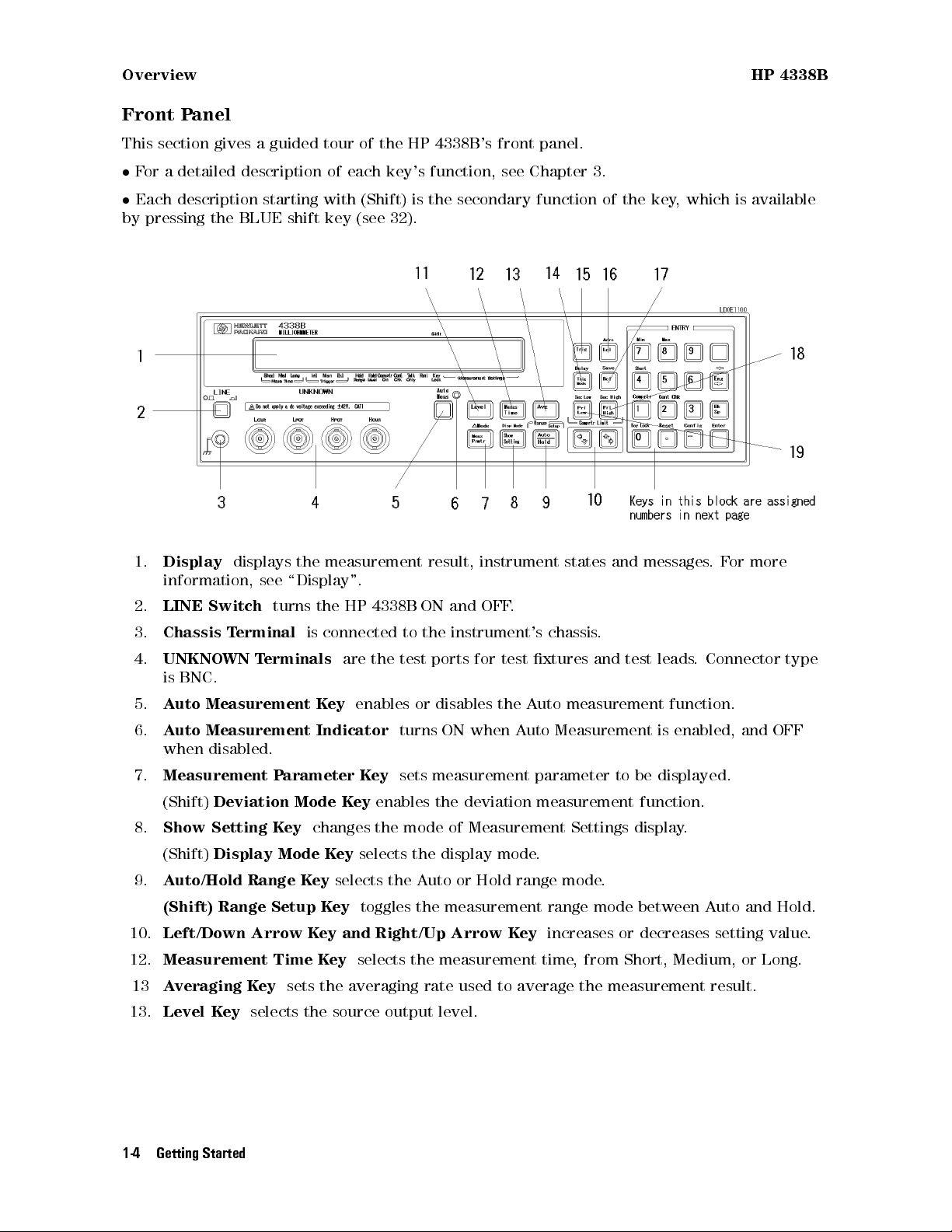
Front Panel
This section gives a guided tour of the HP 4338B's front panel.
For a detailed description of each key's function, see Chapter 3.
Each description starting with (Shift) is the secondary function of the key, which is available
by pressing the BLUE shift key (see 32).
1.
Display
displays the measurement result, instrument states and messages.For more
information, see \Display".
2.
LINE Switch
3.
Chassis Terminal
4.
UNKNOWN Terminals
turns the HP 4338B ON and OFF.
is connected to the instrument's chassis.
are the test ports for test xtures and test leads
is BNC.
5.
Auto Measurement Key
6.
Auto Measurement Indicator
enables or disables the Auto measurement function.
turns ON when Auto Measurement is enabled, and OFF
when disabled.
7.
Measurement Parameter Key
(Shift)
8.
Show Setting Key
(Shift)
9.
Auto/Hold Range Key
Deviation Mode Key
changes the mode of Measurement Settings display.
Display Mode Key
selects the Auto or Hold range mode.
(Shift) Range Setup Key
10.
Left/Down Arrow Key and Right/Up Arrow Key
12.
Measurement Time Key
13
Averaging Key
13.
Level Key
sets the averaging rate used to average the measurement result.
selects the source output level.
sets measurement parameter to be displayed.
enables the deviation measurement function.
selects the display mode.
toggles the measurement range mode between Auto and Hold.
selects the measurement time, from Short, Medium, or Long.
. Connector type
increases or decreases setting value.
1-4 Getting Started
Page 24
HP 4338B Overview
14.
Trigger Mode Key
(Shift)
15.
Trigger Key
16.
Local Key
(Shift)
17.
Recall Key
(Shift)
18.
Primary Comparator Upper Limit (Pri High) Key -
Delay Key
returns the HP 4338B to the local mode from the HP-IB remote mode.
Address Key
recalls the instrument state data from HP 4338B's internal memory.
Save Key
selects the trigger mode.
selects the trigger source from Internal, Manual, or External.
triggers a measurement when in the Manual trigger mode.
sets the HP 4338B's HP-IB address.
saves the instrument state data to the HP 4338B's internal memory.
sets the upper limit of the
comparator function for the primary comparator.
(Shift) Secondary Comparator Upper Limit (Sec High) Key
- sets the upper limit of the
comparator function for the secondary comparator.
19.
Primary Comparator Lower Limit (Pri Low) Key -
sets the lower limit of the
comparator function for the primary comparator.
(Shift) Secondary Comparator Lower Limit (Sec Low) Key
comparator function for the secondary comparator.
20.
0Key
/ (Shift)
Key Lock Key
locks out all key
input except for this key.
21.
.Key
/ (Shift)
Reset Key
resets the
HP 4338B to its default state.
22.0Key
/ (Shift)
Conguration Key
sets the
beep setting and power line frequency setting,
and executes the internal test.
23.
3Key
24.
2Key
the contact check function between ON and OFF
25.
1Key
/ (Shift)
/ (Shift)
Contact Check Key
Comparator Key
toggles
.
toggles
the comparator function between ON and OFF.
26.
4Key
/ (Shift)
Short Key
a SHORT correction
measurement to get correction data.
27.
5Key
28.
29.
30.
31.
7Key
8Key
6Key
9Key
/ (Shift)
/ (Shift)
Minimum Key
Maximum Key
enters the minimum value when setting a parameter.
enters maximum value when setting a parameter.
- sets the lower limit of the
32.
BLUE Shift Key
Note
activates secondary functions printed above the front-panel keys.
In this manual, the BLUE shift key is expressed as , the top of the key is
not labeled with \blue".
Getting Started 1-5
Page 25

Overview HP 4338B
33.
Engineering Unit Key
34.
Back Space Key
35.
Enter Key
terminates key entry.
enters the engineering units,p,n,, m, k, and M.
erases the last entered character when entering numeric values.
1-6 Getting Started
Page 26
HP 4338B Overview
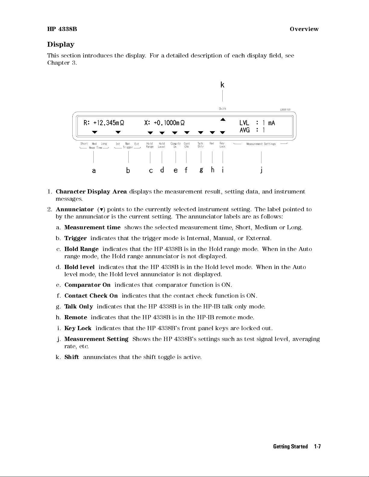
Display
This section introduces the display.For a detailed description of each display eld, see
Chapter 3.
1.
Character Display Area
displays the measurement result, setting data, and instrument
messages.
2.
Annunciator(9
) points to the currently selected instrument setting. The label pointed to
by the annunciator is the current setting. The annunciator labels are as follows:
a.
Measurement time
b.
Trigger
c.
Hold Range
indicates that the trigger mode is Internal, Manual, or External.
indicates that the HP 4338B is in the Hold range mode
shows the selected measurement time, Short, Medium or Long.
. When in the Auto
range mode, the Hold range annunciator is not displayed.
d.
Hold level
indicates that the HP 4338B is in the Hold level mode
. When in the Auto
level mode, the Hold level annunciator is not displayed.
e.
Comparator On
f.
Contact Check On
g.
Talk Only
h.
Remote
i.
Key Lock
j.
Measurement Setting
indicates that the HP 4338B is in the HP-IB remote mode.
indicates that the HP 4338B's front panel keys are locked out.
indicates that comparator function is ON.
indicates that the contact check function is ON.
indicates that the HP 4338B is in the HP-IB talk only mode.
Shows the HP 4338B's settings such as test signal level, averaging
rate, etc.
k.
Shift
annunciates that the shift toggle is active.
Getting Started 1-7
Page 27
Overview HP 4338B
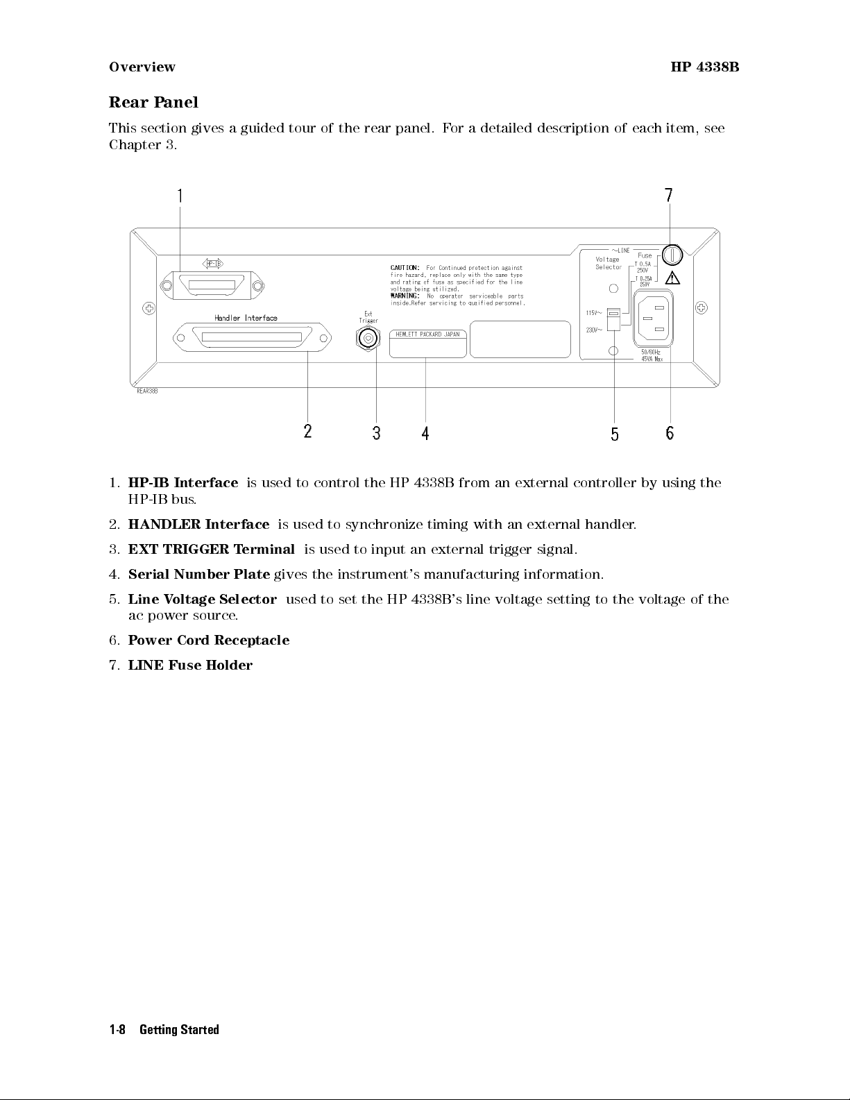
Rear Panel
This section gives a guided tour of the rear panel. For a detailed description of each item, see
Chapter 3.
1.
HP-IB Interface
HP-IB bus.
2.
HANDLER Interface
3.
EXT TRIGGER Terminal
4.
Serial Number Plate
5.
Line Voltage Selector
ac power source.
6.
Power Cord Receptacle
7.
LINE Fuse Holder
is used to control the HP 4338B from an external controller by using the
is used to synchronize timing with an external handler
is used to input an external trigger signal.
gives the instrument's manufacturing information.
used to set the HP 4338B's line voltage setting to the voltage of the
.
1-8 Getting Started
Page 28
HP 4338B Overview
Incoming Inspection
Warning
Inspect the shipping container for damage. If the shipping container or cushioning material
is damaged, it should be kept until the contents of the shipment have been checked for
completeness and the HP 4338B has been checked mechanically and electrically. The contents
of the shipment are as follows:
HP 4338B LCR Meter
Power Cable
Operation Manual(This Book)
User's Guide
If the contents are incomplete, if there is mechanical damage or defect, or if the analyzer does
not pass the power-on selftests, notify the nearest Hewlett-Packard oce. If the shipping
container is damaged, or the cushioning material shows signs of unusual stress
carrier as well as the Hewlett-Packard oce. Keep the shipping materials for the carrier's
inspection.
To avoid hazardous electrical shock, do not turn on the HP 4338B when
there are signs of shipping damage to any portion of the outer enclosure
(for example, covers, panel, or display)
, notify the
Ventilation Requirements
To ensure adequate ventilation, make sure that there is adequate clearance of at least 400 mm
behind, 100 mm sides and 15 mm above.
Instruction for Cleaning
For cleaning, wipe with soft cloth that is soaked with water and wrung tightly without undue
pressure.
Getting Started 1-9
Page 29
Overview HP 4338B
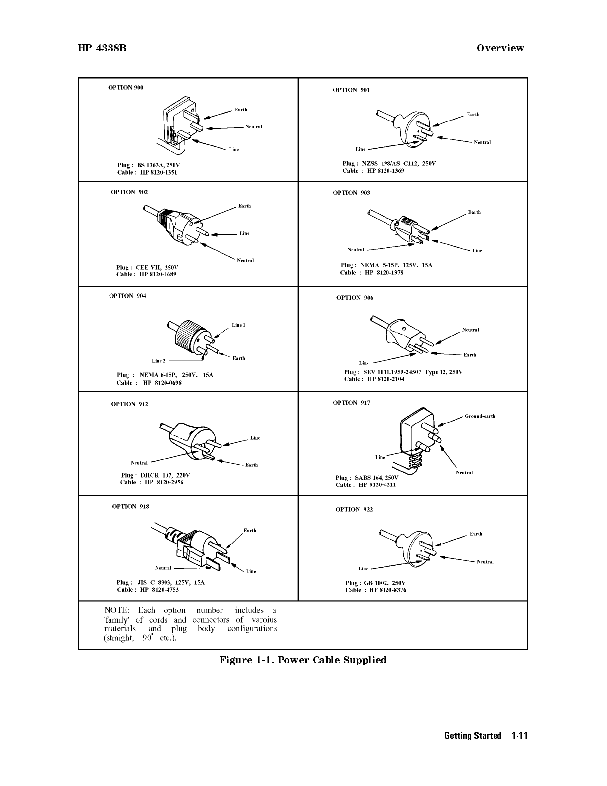
Power Cable
In accordance with international safety standards, this instrument is equipped with a
three-wire power cable. When connected to an appropriate ac power outlet, this cable grounds
the instrument frame. The type of power cable shipped with each instrument depends on the
country of destination. Refer to Figure 1-1 for the part numbers of the power cables available.
Warning
For protection from electrical shock, the power cable ground must not be
defeated. The power plug must be plugged into an outlet that provides a
protective earth ground connection.
1-10 Getting Started
Page 30
HP 4338B Overview
Figure 1-1. Power Cable Supplied
Getting Started 1-11
Page 31

Preparation for Use HP 4338B
Preparation for Use
Before you use the HP 4338B, you must set the HP 4338B to match the available power line
voltage and frequency.
set line voltage | see \Power Requirements".
set line frequency | see \Turning ON the HP 4338B".
Power Requirements
The HP 4338B's power source requirements are as follows:
Power Line Voltage :
PowerLine Frequency :
Power Consumption :
100/120/220/240 Vac(610%)
47 to 66Hz
45 VA maximum
Conrm that the LINE Voltage Selector on rear panel is set to match the power line voltage
before plugging in the HP 4338B. Refer to Figure 1-2
1. Conrm that the power cable is disconnected.
2. Slide the LINE V
oltage Selector on the rear panel to match your power line voltage
. When
your power line voltage is 100/120 Vac(610%), slide the Selector to 115 V. When your power
line voltage is 220/240 Vac(610%), slide the Selector to 230 V. See Figure 1-2.
Fuse
Use the fuse shown in Table 1-1. If you require the fuse, contact the nearest Hewlett-Packard
sales oce.
The fuse can be replaced by turning the fuse holder shown in Figure 1-2 counterclockwise until
the fuse holder pops out with a minus screw driver
.
Figure 1-2. Voltage Selector and Fuse
Table 1-1. Line Voltage Selection
Voltage Selector Power Line
115V 100/120Vac(610%) UL/CSA type, Time delay 0.5A 250V
230V 220/240Vac(610%) UL/CSA type, Time delay 0.25A 250V
1-12 Getting Started
Required Fuse
Voltage
(HP part number 2110-0202)
(HP part number 2110-0201)
Page 32

HP 4338B Preparation for Use
Turning ON the HP 4338B
1. Connect the power cable to the power cord receptacle on the rear panel.
2. Push the LINE switch in. The HP 4338B will emit a beep when it turns ON and perform the
self test. (If any message is displayed, see \Error Messages" in the back of this manual.) The
HP 4338B will be ready for operation after a message like the one shown in the following
gure is displayed.
3. Conrm that the power line frequency setting is correct.
a. Press . The following menu is displayed.
b. Press until the
A blinking item is selected.
c. If the setting does not match the ac line frequency, press
between
d. Press two times to exit this menu.
The power line frequency setting is stored and does not change after reset or on power-o.
Once you set it, you do not need to set the line frequency again as long as the same power line
frequency is being used.
50 Hz
and
Line
blinks, then Press .
60 Hz
.
to toggle the setting
Getting Started 1-13
Page 33

Using Front-Panel Keys HP 4338B
Using Front-Panel Keys
The HP 4338B has four types of keys as follows:
Direct Execution Keys
Toggle Keys
Selection Keys
Value Setup Keys
This section describes how to use the HP 4338B's front panel keys.
Note
If you want to exit an operation and go back to the measurement display, press
several times.
Direct Execution Keys
Pressing a direct execution key will cause the pressed key's function to be performed
immediately.For example,
Press
, and the HP 4338B's front panel keys are locked out.
Toggle Keys
Pressing a toggle key will switch between several conditions
. An annunciator will indicate the
current condition. For example,
Press
, and the
Meas Time
annunciator(9) alternately points to the current setting
(Short, Med or Long).
Selection Keys
Pressing a selection key will display the selection display. The blinking item is the one
currently selected. By using
, , or the selection key itself, the selected (blinking) items
can be changed.
For example, to perform the self test,
1. Press .
2. Press to blink
3. Press
Exit
is blinking.
Test
.
. The self test will start immediately. After the test is nished, the HP 4338B will
display any existing error code, and return to the menu.
4. Select
Exit
and press
to exit the menu.
1-14 Getting Started
Page 34
HP 4338B Using Front-Panel Keys
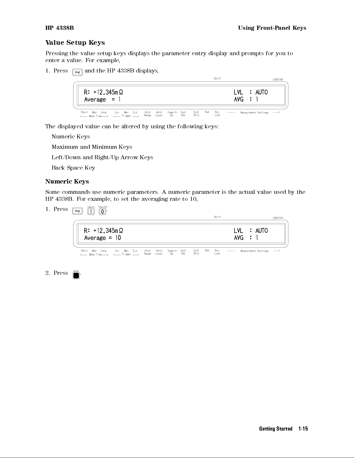
Value Setup Keys
Pressing the value setup keys displays the parameter entry display and prompts for you to
enter a value.For example,
1. Press and the HP 4338B displays,
The displayed value can be altered by using the following keys:
Numeric Keys
Maximum and Minimum Keys
Left/Down and Right/Up Arrow Keys
Back Space Key
Numeric Keys
Some commands use numeric parameters. A numeric parameter is the actual value used by the
HP 4338B. For example, to set the averaging rate to 10,
1. Press
2. Press .
.
Getting Started 1-15
Page 35

Using Front-Panel Keys HP 4338B
You can also enter numeric parameters using engineering units.
1. Press
2. Press
3. Press and the engineering unit will be displayed with
displayed.
4. Press more several times and the engineering units are displayed alternately in
increasing order.
5. Press
. The comparator limit menu is displayed.
.
100
.For example
, and the engineering unit previously displayed will be displayed again.
100K
will
6. Press to enter the value and exit this menu.
Note
Maximum and Minimum Keys
These keys enter the maximum and minimum numeric value in place of using the numeric
keys.For example,
1. Press
2. Press to enter the value and exit this menu.
Before you press , the previous setting is still the current setting, even
though the displayed value has changed. If you press a key other than one of
the keys in ENTRY block before pressing , the setting will not change and
the displayed value will be discarded.
and you will get the maximum value of averaging rate (256).
1-16 Getting Started
Page 36

HP 4338B Using Front-Panel Keys
Left/Down and Right/Up Arrow Keys
Increments or decrements numeric entry.For example,
1. Press
2. Press several times and conrm a change in value.
3. Press
Back Space Key
Erases the last entered character, and cancels the input value.For example,
1. Press
2. Press .
3. Press .
to bring up the HP-IB address setup display.
to exit the setup display.
to select comparator limit menu.
Last entered4is erased.
Getting Started 1-17
Page 37

Connecting a Test Fixture HP 4338B
ToPerform a Measurement
The following procedure is commonly used to perform a measurement using the HP 4338B:
1. Conguration setup
2. Turning on the HP 4338B
3. Connecting DUT to test xture
4. Correction
5. Setting parameters
6. Measurement
This section provides the basic measurement procedure for using the HP 4338B. Follow the
instructions and get to know about the HP 4338B.
To Connect Test Fixture
To Reset HP 4338B
ToPerform Short Correction
To Select Measurement Parameter
To Select Auto Measurement Mode
To Select Measurement Range
To Set Test Voltage
Caution
Note
DO NOT apply a dc voltage exceeding642 V to UNKNOWN terminals, or input
circuit of the HP 4338B will be destroyed.
If you have any problems operating the HP 4338B, see \If Y
in Chapter 2.
ou Have a Problem"
1-18 Getting Started
Page 38

HP 4338B To Reset HP 4338B
Connecting a Test Fixture
The following describes the available test xtures for the HP 4338B and their connection to the
HP 4338B.
Note
Using the HP 16338A
The HP 16338A test lead set contains four types of test leads, which are used depending on the
DUT type.
The HP 16338A Test Lead set is available for the HP 4338B. Other xtures
must NOT be used with the HP 4338B, even if the UNKNOWN terminals
physically match a test xture's connector spacing because the terminals'
conguration is dierent.
Figure 1-3. Connecting HP 16338A
Getting Started 1-19
Page 39

ToPerform a SHORT Correction HP 4338B
To Reset HP 4338B
Resetting the HP 4338B sets its settings to their default states.
1. Press
2. Press to select
to select the reset menu.
Yes(Yes
blinks), then press .
The HP 4338B is now set to the default state.For more information about the default state,
refer to \Reset Key
" in Chapter 3.
ToPerform a SHORT Correction
Correction is used to cancel the residual errors of the cables and the test xture
correction cancels residual impedance in series with the DUT
.
. The SHORT
1. Connect the electrodes of xture to obtain a SHORT condition.
Note
The SHORT condition is obtained by using a shorting bar
, or by connecting
the test leads together.For details on making a good SHORT, see the manual
supplied with the test xture being used.
2. Press
3. Press or until
. The SHORT correction menu is displayed.
ShortMeas
blinks, and press . The SHORT correction is in
progress, and the following message is displayed.
After a short time, the HP 4338B will display the message
"Short Correction Complete"
and return to the normal display.
If the SHORT impedancejZsjis NOT less than 10 , which is unsuitable for use as the SHORT
correction data, the HP 4338B will display the following warning message
.
,
1-20 Getting Started
Page 40
HP 4338B ToPerform a SHORT Correction
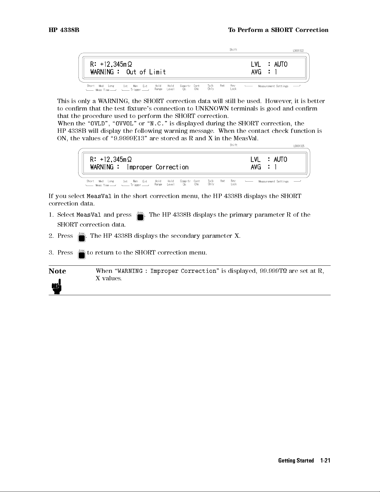
This is only a WARNING, the SHORT correction data will still be used. However, it is better
to conrm that the test xture's connection to UNKNOWN terminals is good and conrm
that the procedure used to perform the SHORT correction.
When the \
HP 4338B will display the following warning message. When the contact check function is
ON, the values of \9.9999E13" are stored as R and X in the MeasVal.
OVLD
", \
OVVOL
"or\
N.C.
" is displayed during the SHORT correction, the
If you select
correction data.
1. Select
SHORT correction data.
2. Press . The HP 4338B displays the secondary parameter X.
3. Press to return to the SHORT correction menu.
Note
MeasVal
MeasVal
When \
X values.
in the short correction menu, the HP 4338B displays the SHORT
and press
WARNING : Improper Correction
. The HP 4338B displays the primary parameter R of the
" is displayed, 99.999T are set at R,
Getting Started 1-21
Page 41

To Select Measurement Range HP 4338B
To Select Measurement Parameter
1. Press
. The following menu is displayed.
2. Press or to select the dsesired parameter, then press .
R
R-X
R-L
Z-
To Select Auto Measurement Mode
The HP 4338B has an Auto Measurement Function which allows automatic selection of the
optimum measurement range and test signal level. To activate the auto measurement mode:
Press
The auto measurement indicator turns ON. If the
.
Hold Range
annunciator(9)or
Hold Level
annunciator(9) is displyed, the indicator turns o.
To Select Test Signal Level
The HP 4338B has ve test current levels | 1
addition to these selection, you can select also the auto level mode
A, 10A, 100A, 1 mA, and 10 mA. In
, in which the HP 4338B
automatically selects the optimum measurement test level. If the test level is set other than
the auto level mode, the
Hold Level
annunciator(9) is displayed.
To select the test level:
.
Auto
1. press
and available test signal levels are displayed.
2. Press or until the desired level blinks. If you want to select the auto level mode,
press
3. Press
or until
.
Auto
blinks.
1-22 Getting Started
Page 42

HP 4338B To Select Measurement Range
To Select Measurement Range
Auto / Hold Range Mode
The HP 4338B has two measurement range modes,Auto and Hold. The Auto mode changes
the measurement range automatically to t the measured value. The Hold mode xes the
measurement range.
To select the range mode,
Press
In Hold range mode, the
when the
Measurement Range Setting
1. Press . Measurement range menu is displayed.
2. Press or until the desired range is displayed.
3. Press .
Note
and the
Hold Range
Hold Range
Hold Range
annunciator is not displayed.
You may nd some measurement range cannot be set because the HP 4338B has
test signal level limitations for each measurement range setting. F
Figure 3-2.
annunciator(9) is alternately displayed and turned o.
annunciator is displayed. The Auto range mode is active
or details, see
Getting Started 1-23
Page 43

Page 44

Operating the HP 4338B
Introduction
This chapter provides step-by-step instructions for using the HP 4338B Milliohmmeter . This
chapter includes the following sections:
Measurement Conguration
Making a measurement
Testing the HP 4338B
If You Have a Problem
Refer to Chapter 3 for the description of each front panel key function.
2
Operating the HP 4338B 2-1
Page 45

Measurement Conguration HP 4338B
Measurement Conguration
This section discusses the HP 4338B's general conguration topics that apply to many or all
measurement functions.
To Select the Measurement Time Mode
The current measurement time mode setting (Short, Med or Long) is indicated by the
Meas Time
annunciator(9). To select the measurement time mode:
1. Press
until the measurement time mode is set to the desired mode.
To Set the Averaging Rate
To set the averaging rate :
1. Press .
2. Enter the desired value.
3. Press
to set the value and to exit.
The current setting is desplayed on the right side of the LCD display
is not displayed, press until it is displayed.
To Set the Trigger Delay or Source Delay Time
To set the trigger delay or the source delay time:
. When the current setting
1. Press
.
To set the trigger delay time:
Press
or until
Enter the desired value using the numeric keys
TrigDelay
blinks, and press .
, and press
When you want to exit without changing value, just press .
2-2 Operating the HP 4338B
.
Page 46

HP 4338B Measurement Conguration
To set the source delay time:
Press or until
Enter the desired value using the numeric keys, and press .
When you want to exit without changing value, just press
To display the current setting, press
side of the LCD display.
To Set the Contact Check
The
Cont Chk
contact check function is turned ON/OFF as follows:
To turn ON the contact check function:
Press
To turn OFF the contact check function:
annunciator(9) indicates the ON/OFF state of the contact check function. The
. The Cont Chk annunciator(9) is displayed.
SourceDelay
blinks, and press .
until the setting value is displayed on the right
.
Press
again. The Cont Chk annunciator(9) disappears.
Operating the HP 4338B 2-3
Page 47

Measurement Conguration HP 4338B
To Set the Beeper Mode
To set the beeper mode for the comparator result reporting:
1. Press
2. Select
3. Select the desired mode (
4. Select
To Save and Recall Instrument Settings
The HP 4338B can save and recall the instrument's settings
To save the current settings:
Beep
Exit
.
using or , and press .
Fail,PassorOff
using or , and press to exit.
) using or , and press .
.
1. Press
2. Enter the register number (0 to 9) that you want to save the settings into
3. Press to save.
Note
.
Record the register number that you saved into for further reference.
.
2-4 Operating the HP 4338B
Page 48

HP 4338B Measurement Conguration
To recall a setting.
1. Press .
2. Enter the register number (0 to 9) that you want to recall the settings from.
3. Press to recall.
Operating the HP 4338B 2-5
Page 49

Making a Measurement HP 4338B
Making a Measurement
To Trigger a Measurement
The HP 4338B has four trigger source modes: Internal, Manual, External, or Bus. The
annunciator shows which trigger source is selected.
Note
To Trigger Internally
1. Press
To Trigger Manually
1. Press until the
2. Press
To Trigger Externally
1. Connect the external trigger source to the EXT TRIGGER terminal on the HP 4338B's rear
panel.
2. Press
3. Apply a trigger signal to trigger the HP 4338B
The bus trigger mode can be set by HP-IB commands only. When the bus
trigger mode is selected, none of the Trigger annunciators are ON.
until the
when you want to trigger a measurement.
until the
Int
trigger annunciator(9) is ON.
Man
trigger annunciator(9) is ON.
Ext
trigger annunciator(9) is ON.
.
Trigger
2-6 Operating the HP 4338B
Page 50

HP 4338B Making a Measurement
To Use the Comparator Function
The comparator function can be used to sort DUTs based on their parameter values. The
Comprtr On
To set the limit values:
1. Select the parameter to be set by pressing or for the primary parameter, and
2. Enter the value using the numeric keys, and press to enter the value.
annunciator(9) tells whether the comparator function is set to ON or OFF.
or for the secondary parameter.
Note
To start sorting:
1. Press
To display the sorting results:
Press
Select
mode, and the comparison result is displayed.
When you want to set the limits only for the lower limit or the upper limit, or
the limits only for the primary parameter or the secondary parameter, set the
unnecessary parameter to OFF using the (setting the minimum value)
or the (setting the maximum value).
.
. The following menu is displayed.
Comprtr
using or . The display mode is set to the comparator result display
To stop sorting:
Press .
Operating the HP 4338B 2-7
Page 51

Making a Measurement HP 4338B
To Display Deviation Data
The1before the measurement parameter on the LCD display tells that the displayed value for
the parameter is the deviation value.
To Set the Reference Value
1. Press . The following menu is displayed.
2. Press or to select
To set by measuring the reference DUT:
a. Press
b. Then the secondary parameter reference setting menu (
Press
value as the secondary reference.
To set by entering a value:
a. Enter the primary parameter reference value using the numeric keys
When you want to exit without changing value, just press .
b. Enter the secondary parameter reference value using the numeric keys, and press .
regardless of the trigger mode, and the primary parameter is measured. Press
to set the measurement value as the primary reference
to measure the secondary parameter, and press to set the measurement
1RefEnt
, and press .
.
1Ref Secondary=
, and press
) is displayed.
.
When you want to exit without changing value, just press .
2-8 Operating the HP 4338B
Page 52

HP 4338B Making a Measurement
To Select the Deviation Display Mode
To select the deviation display mode (
3. To select the primary parameter deviation display mode, press
press .
Press or to select
4. To select the secondary parameter deviation display mode, press or to select
and press . The same menu as the primary parameter is displayed, and you can select
the mode (
Off, 1ABSor1
Off,1ABS
%) in the same manner as the primary parameter.
Off,1
,or1%),
,or1%, and press .
or to select
Pri
, and
Sec
,
Operating the HP 4338B 2-9
Page 53

Making a Measurement HP 4338B
To Set the Display Mode and Display Digits
If you press
or (
Off
: turns the display OFF) and press
To exit from this menu, select
If you select
using or , and press . After selecting the display digits, the HP 4338B returns to
the display mode selection menu.
Data
Digit
, the display mode selection menu appears. Select the desired mode using
: displays the measurement data,
.
Exit
and press .
, the display digits selection menu appears. Select the desired display digits
Comprtr
: displays the comparator results,
2-10 Operating the HP 4338B
Page 54

HP 4338B Making a Measurement
To Change the Measurement Settings Display Mode
Each time
is pressed, the current settings of the HP 4338B are displayed one after
another on the right side of the LCD display. The information displayed and the order of
display is as follows:
1. Test signal level and Averaging rate
2. Trigger delay time and Source delay time
3. Comparator limits of the primary parameter
4. Comparator limits of the secondary parameter
Operating the HP 4338B 2-11
Page 55

Making a Measurement HP 4338B
To Lock Out the Front Panel Keys
To lockout the keys:
Press
.
To unlock the keys:
Press again.
To Select the Local Mode
To return the HP 4338B to the local mode from HP-IB remote mode:
Press
.
To Set the HP-IB Address
1. Press
.
2. Enter the desired value, then press to set the value and to exit.
When you just want to show the current setting, just press .
To Print Measurement Data
To print the measurement data to an HP-IB compatible printer without using an external
controller:
1. Set the printer to listen-always mode.
2. Connect the HP-IB compatible printer to the HP 4338B's HP-IB port.
3. Turn the printer ON.
4. Set the HP 4338B's HP-IB address to 31 (talk only mode).
Press
.
The printer will begin printing the measurement data.
5. When you want to stop printing, change the HP 4338B's HP-IB address to an address other
than 31 (for example, 17, which is the default setting).
Press
.
2-12 Operating the HP 4338B
Page 56

HP 4338B ToTest the HP 4338B
ToTest the HP 4338B
ToPerform a Self-Test
The HP 4338B has a self-test function to check its basic performance.
1. Press
2. Select
Test
.
using or , then press to execute the self test. If any error message
is displayed, refer to \Error Messages".
3. Select
Exit
and press to exit.
ToTest the Front Panel Keys' Functionality
The HP 4338B has a service function to test the functionality of the front panel keys
, the
handler interface, the ROM, the RAM, and the EEPROM. This section describes how to test
the front panel key's functionality.For the handler interface test, refer to Chapter 9 for the
procedure. The other tests are for use by service personnel only
1. Press
2. Select
Svc
.
using or and press .
.
3. Select
KEY
using ,or and press .
4. Press the front panel key that you want to test.
For example, if you want to test , then press .
When the key functions properly,
KEY CODE:5 TRIGGER
is displayed; otherwise, there will be
no such display, the key is not functioning correctly. Contact your nearest Hewlett-Packard
oce.
5. When you want to exit the front panel key test, press
6. Select
Exit
and press
to exit.
twice.
Operating the HP 4338B 2-13
Page 57

If You Have a Problem HP 4338B
If You Have a Problem
If any of the problems listed below occur, follow the instructions described.
If the Display is Blank and the HP 4338B Appears Dead
If the display is blank, and even the annunciators are not ON:
Check the fuse.
If an Error Message is Displayed
Refer to \Messages."
If the HP 4338B does not Accept Any Key Input
Check whether the
Rmt
annunciator is ON.
Check whether the external controller disables all the front-panel controls by
the
LOCAL LOCKOUT
If so, send the
Press
.
Check whether the
command.
LOCAL
Key Lock
command from the external controller.
annunciator is ON.
Check whether the handler or the HP 16064B LED display/trigger box is connected to the
HP 4338B and it locks out the keys.
If so, unlock the keys from the handler or the HP 16064B
Press
.
.
2-14 Operating the HP 4338B
Page 58

Function Reference
Introduction
This chapter provides information on all of the HP 4338B's functions.
Front Panel
Rear Panel
Theory of Operation
3
Function Reference 3-1
Page 59

Front Panel HP 4338B
Front Panel
Figure 3-1. Front Panel
Note
In this manual, the BLUE shift key is expressed as , top of the key is not
labeled with \blue".
Display
The display has two functions | the character display and an annunciator display
.
The character display displays the measurement result, setting data, and instrument messages
The HP 4338B has four measurement display modes.For details on the display modes, refer to
\Display Mode Key
".
The annunciator (9) points to the current setting of the HP 4338B. The annunciators are:
Meas Time
Trigger
Hold Range
(Measurement Time) indicates measurement time | Short, Medium or Long.
indicates the trigger mode | Internal, Manual, or External.
shows the measurement range mode | Hold (when the annunciator is
displayed) or Auto (when the annunciator is not displayed).
Hold Level
indicates that the HP 4338B is in the Hold level mode. When in the Auto level
mode, the Hold level annunciator is not displayed.
Cmprtr On
Cont Chk
(Comparator On) indicates the comparator function is ON.
(Contact Check On) indicates the contact check function is ON.
.
Talk Only
(Talk Only mode) indicates the HP 4338B is performing an HP-IB input or
output data transfer.
Rmt
Key Lock
Shift
(Remote) indicates the HP 4338B is in the HP-IB remote mode.
indicates the HP 4338B's front panel keys are disabled.
indicates the secondary key functions (printed above the keys in BLUE
characters) are the active functions.
3-2 Function Reference
Page 60

HP 4338B Front Panel
LINE Switch
Power ON/OFF switch. In the 1 (ON) position power is applied and all operating voltages
are applied to the instrument. In the 0 (OFF) position no power is applied and no operating
voltages are applied to the instrument.
The HP 4338B's settings are held in backup memory for 72 hours after power is turned OFF,
and are restored as the current settings when power is turned ON again within the 72 hours
period. The backed up settings are:
Auto level mode
Test signal level
Source delay
Measurement parameter
Deviation mode
Deviation reference value
Auto / Hold range mode
Measurement range setting
Measurement time
Averaging
Trigger mode
Trigger delay
Comparator ON/OFF state
High and low limit value
Display mode
Chassis Terminal
The Chassis terminal is tied to the instrument's chassis
.
UNKNOWN Terminals
These terminals are used to connect test xtures or test leads for measuring a DUT
. The
connector type is BNC.
Caution
DO NOT apply a dc voltage exceeding642 V to UNKNOWN terminals, or the
HP 4338B's input circuits will be destroyed.
Auto Measurement Key
The Auto Measurement key enables the Auto measurement function which allows the
HP 4338B to measure a DUT automatically using the optimum measurement range and test
signal level.
When the auto measurement function enabled, the HP 4338B is set to the auto range mode (see
\Auto / Hold range Key
") and auto level mode (see \Level Key ").
When the Auto measurement function is enabled, the Auto Measurement indicator turns ON.
Note
The Auto Measurement key doesn't disable the Auto measurement function.
And the Auto measurement function is disabled when auto range or auto level
is disabled.
Function Reference 3-3
Page 61

Front Panel HP 4338B
Level Key
The level key sets the test signal level. The available test signal levels are 1Arms, 10Arms,
100Arms, 1 mArms, and 10 mArms. Figure 3-2 shows the available measurement range for
each test level.
Figure 3-2. Test Level and Measurement Range Setup
If the measurement range setting doesn't match the test signal level you choose
selects the nearest measurement range from the current setting that satises the measurement
limits for the selected test signal level.
The level key can also select the auto level mode. In the auto level mode, the test signal level
is linked to the measurement range settings as follows:
Range
Level
When the auto level mode is not selected, the Hold level annuunciator is displayed.
Note
10 k 1k 100 10 1 100 m 10 m 1m
1A 10A 100A 1mA 10 mA
The HP 4338B's test signal output is enabled when a measurement is triggered,
and disabled when the measurement is completed (See \Delay Key").
, the HP 4338B
3-4 Function Reference
Page 62

HP 4338B Front Panel
Note
The peak voltage across the DUT must always be less than 20 mV. When the
peak voltage across the DUT exceeds 20 mV , the source output level goes to
0 V, and the HP 4338B displays \
OVVOL
". For details, see \Dry Circuit Loop"in
Chapter 7.
Measurement Parameter Key
The Measurement Parameter key selects the measurement parameter. The HP 4338B has the
following measurement parameters:
R (default)
R-L (series circuit)
R-X
Z-
Where,
R Resistance
L Inductance
X Reactance
Z Absolute value of Impedance
Phase Angle(deg)
Deviation Mode Key
The Deviation mode (1 mode) key selects the deviation measurement mode which displays the
dierence between the measured value a user entered nominal value and sets the nominal
value of the deviation measurement.
1 ABS mode
1 % mode
displays the dierence between the measured value and the nominal value
displays the dierence between the measurement value and the nominal value
.
as a percentage of the nominal value.
O
turns OFF the deviation measurement mode. (default)
Measurement Time Key
The Measurement Time key toggles the measurement time between Short, Medium, and Long.
The current setting is indicated by the
Meas Time
annunciator(9). While a Short measurement
time setting gives the shortest measurement time, a Long measurement time will give the more
accurate result. The default measurement time is Medium.
Show Setting Key
The Show Setting Key displays the current settings of the HP 4338B. The settings are
sequentially displayed on the right side of the LCD display (
time
is pressed. The following information is displayed:
Measurement Settings
area) each
Test signal level and Averaging rate
Trigger delay time and Source delay time
Comparator limits of the primary parameter
Comparator limits of the secondary parameter
Function Reference 3-5
Page 63

Front Panel HP 4338B
Display Mode Key
The Display Mode key sets the HP 4338B to one of the following four display modes:
Data
Comprtr
O
Also, if you select
Digit
displays the measurement result. (default)
displays the result message of the comparator as
the upper limit),IN(passed),
N.C.
(contact check fail).
LOW
(less than the lower limit) and
HIGH
(grater than
does not display any measurement result (Display OFF).
in this menu, you can set the number of digits for the measurement
data. The available digits are 3, 4, and 5.
Average Key
The Average key sets the measurement averaging rate. The HP 4338B averages the
measurement results automatically. The averaging rate can be set from 1 to 256. The default
averaging rate is 1.
Auto / Hold range Key
The Auto/Hold range key toggles the measurement ranging mode between A
uto and Hold.
The Auto mode selects the optimum measurement range automatically within 5 measurement
cycles. The Hold mode xes the measurement range setting to the range you select. When
the Hold mode is selected, the
Hold Range
annunciator(9) will be displayed. The default
measurement range mode is Auto.
Range Setup Key
The Range setup key sets the measurement range. The available measurement range settings
are 1 m, 10 m, 100 m, 1 , 10 , 100 , 1 k, and 10 k, which are limited by test level
setting. (See Figure 3-2.)
When the measured impedance is out of range and the HP 4338B cannot measure at the
currently set range setting, \
OVLD
" is displayed.
Trigger Key
The Trigger key triggers a measurement when in the manual trigger mode. (see \Trigger Mode
Key
").
3-6 Function Reference
Page 64

HP 4338B Front Panel
Trigger Mode Key
The Trigger mode key toggles three trigger mode | Internal, Manual, or External. The
HP 4338B also has a BUS trigger mode.
Internal (Int)
The internal trigger mode. In this mode measurements are free running and
continuous. (Default)
Manual (Man)
External (Ext)
The manual trigger mode. In the manual mode, the HP 4338B performs a
single measurement when the front-panel
key is pushed.
The external trigger mode. The HP 4338B is triggered by a TTL pulse input
through the rear panel External Trigger connector, or through the handler
interface.For more information, refer to \External Trigger" in \Rear
Panel".
Bus mode
(HP-IB only)
This mode is available only when in the HP-IB remote state. In the BUS
trigger mode, the
GET
and
*TRG
commands will trigger a single shot
measurement. For more information, refer to \TRIGger Subsystem"in
Chapter 5.
The mode selected is indicated by the
Trigger
annunciator(9). (In the BUS mode, the
annunciator is not displayed).
Delay Key
The Delay key sets the trigger delay time and the source delay time
. The delay time
species the time interval from the time at which the trigger occurs to the actual start of the
measurement, as shown in Figure 3-3. Each delay time can be set 0 ms to 9999 ms with 1 ms
resolution. The default delay time is 0 ms.
Figure 3-3. Source Delay and Trigger Delay
Function Reference 3-7
Page 65

Front Panel HP 4338B
Local Key
The Local key returns the HP 4338B to the local mode (front-panel) operation from the HP-IB
remote mode (computer controlled). This key is the only front-panel key activated while the
HP 4338B is in the remote state.
When the HP 4338B is in the remote mode, the
Rmt
annunciator(9) will be displayed.
Address Key
The Address key sets the HP 4338B's HP-IB address. The available HP-IB addresses are the
integer numbers from 0 to 30. Address 31 is the talk only mode in which the HP 4338B sends
data through HP-IB interface.
In the talk only mode, output data is,
<
stat>,<data1>,<data2>,<comp1>,<comp2
>
Where,
<
stat>measured status of each channel
0 : normal
1 : overload
2 : no contact
4 : over voltage
<
data1>measurement data of primary parameter
<
data2>measurement data of secondary parameter
(Meaningless output when the secondary parameter is
none)
<
comp1>comparison result of primary parameter
(No output when the comparator function is OFF)
<
comp2>comparison result of secondary parameter
(No output when the comparator function is OFF)
(Meaningless output when the secondary parameter is
none)
1: In
2 : High
4 : Low
8 : no contact
System reset or power-on don't aect the address setting.
Save Key
The Save key stores the HP 4338B's current settings in non-volatile memory (EEPROM). The
settings saved are the same as the backup settings listed in \LINE Switch" description. You
must enter the register number, 0 to 9, to assign the register into which the settings will be
saved. Up to 10 sets of instrument settings can be saved.
Caution
The HP 4338B overwrites the instrument's setting into the assigned register
without notice, if settings are already stored in the assigned register
, the
settings will be lost when the new settings overwrite them.
3-8 Function Reference
Page 66
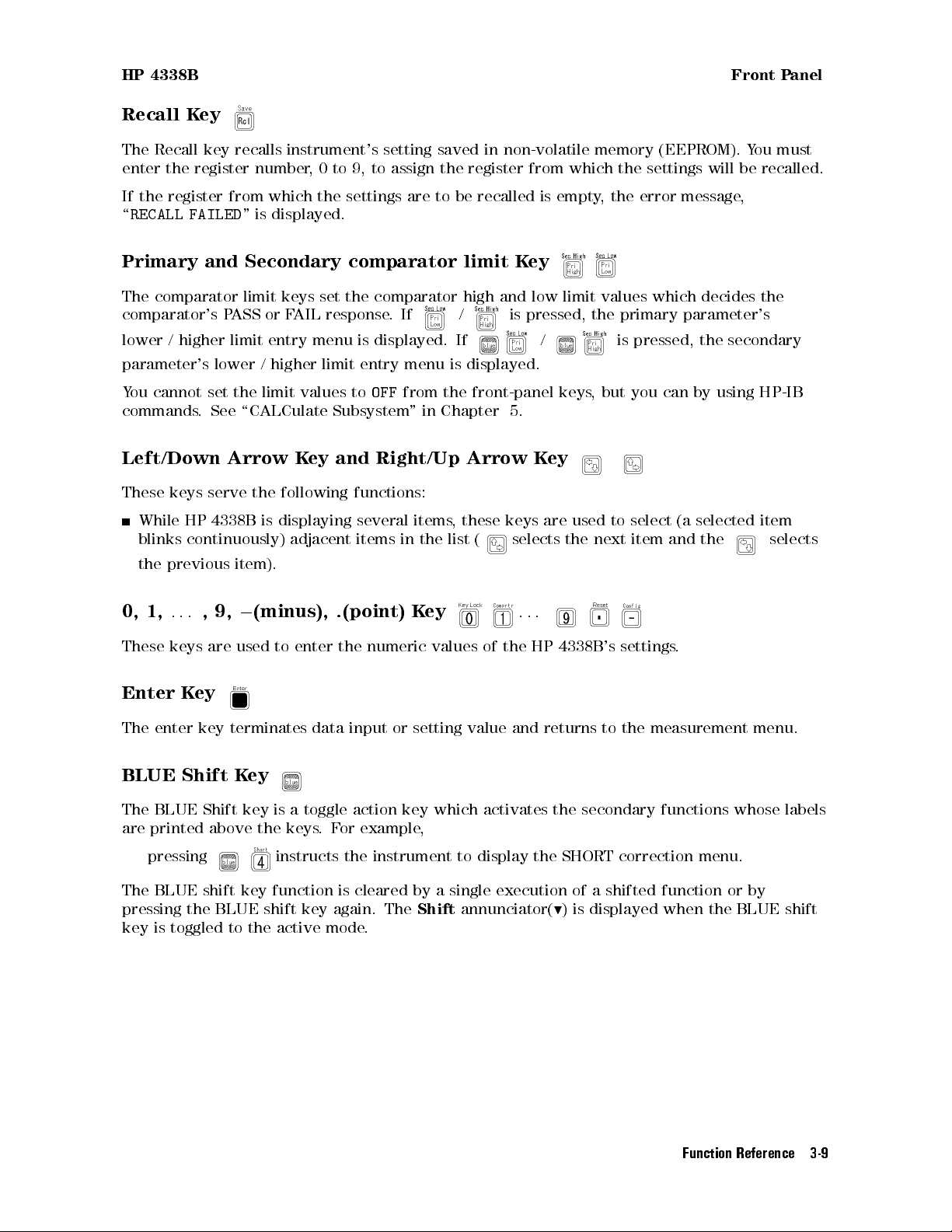
HP 4338B Front Panel
Recall Key
The Recall key recalls instrument's setting saved in non-volatile memory (EEPROM). You must
enter the register number, 0 to 9, to assign the register from which the settings will be recalled.
If the register from which the settings are to be recalled is empty, the error message,
\
RECALL FAILED
" is displayed.
Primary and Secondary comparator limit Key
The comparator limit keys set the comparator high and low limit values which decides the
comparator's PASS or FAIL response.If / is pressed, the primary parameter's
lower / higher limit entry menu is displayed. If / is pressed, the secondary
parameter's lower / higher limit entry menu is displayed.
You cannot set the limit values to
OFF
from the front-panel keys, but you can by using HP-IB
commands. See \CALCulate Subsystem" in Chapter 5.
Left/Down Arrow Key and Right/Up Arrow Key
These keys serve the following functions:
While HP 4338B is displaying several items, these keys are used to select (a selected item
blinks continuously) adjacent items in the list (
selects the next item and the selects
the previous item).
0, 1,
These keys are used to enter the numeric values of the HP 4338B's settings
...
,9,0(minus), .(point) Key
...
.
Enter Key
The enter key terminates data input or setting value and returns to the measurement menu.
BLUE Shift Key
The BLUE Shift key is a toggle action key which activates the secondary functions whose labels
are printed above the keys.For example,
pressing instructs the instrument to display the SHORT correction menu.
The BLUE shift key function is cleared by a single execution of a shifted function or by
pressing the BLUE shift key again. The
Shift
annunciator(9) is displayed when the BLUE shift
key is toggled to the active mode.
Function Reference 3-9
Page 67

Front Panel HP 4338B
Engineering units Key
The Engineering units key enters engineering units. The available engineering units are:
0
f (femto)
p (pico)
n (nano)
(micro)
m (milli)
15
2
10
0
12
2
10
0
9
2
10
0
6
2
10
0
3
2
10
k (kilo)
M (mega)
G (giga)
T (tera)
3
2
10
6
2
10
9
2
10
12
2
10
Press
, the unit is displayed in increasing order. Press , the unit is displayed in
decreasing order.
Back Space Key
The Back Space key deletes a single preceding character of an input value.
Minimum Key
The Minimum key enters the minimum value during a setting operation.
Maximum Key
The Maximum key enters the maximum value during a setting operation.
Comparator Key
The Comparator key toggles the comparator function ON and OFF
. The default comparator
function is OFF.
The Comparator distinguishes whether or not the measurement result is within the upper
and lower comparator limits for primary and secondary measurement parameter
comparator function is ON, the
Comprtr On
annunciator(9) will be displayed. The comparison
. When the
results output is assigned as follows:
Destination Condition
Comparison Display : HIGH, IN, LOW, N.C.
Handler Interface : HIGH, IN, LOW, N.C.
Beep (FAIL mode) : HIGH, LOW, N.C.
(PASS mode) :IN
Where,
HIGH greater than the upper limit
IN between the upper limit and the lower limit
LOW less than the lower limit
N.C. contact check failed
When measurement parameter changes, the comparator function is automatically turned OFF
3-10 Function Reference
.
Page 68

HP 4338B Front Panel
Contact Check Key
The contact check key toggles the contact check function ON and OFF. This function monitors
whether the DUT is properly connected to the measurement terminals. When the no-contact is
detected, the HP 4338B displays \
When the contact check function is ON, the
N.C.
". The default state is OFF.
Cont Chk
annunciator(9) will be displayed.
Short Key
The Short key executes the SHORT correction function. The SHORT correction measurement
must be performed when the high terminal and low terminals are directly shorted together or
with a low-impedance, high-quality shorting device. The HP 4338B takes measurement data
under these conditions and uses the correction data to cancel measurement errors due to the
residual impedance of cable and test xture. The correction data is stored in non-volatile
memory(EEPROM).
Press
ShortMeas
MeasVal
Exit
If the short impedance,jZsj, is NOT less than 10 , the HP 4338B displays
\
WARNING: Out Of Limit
, the following SHORT correction menu is displayed.
Performs the SHORT correction.
Displays the SHORT correction data (R, X).
Exits the menu.
,
"
This is only a WARNING, the SHORT correction data will still be used.
When the \
will display,\
values of \9.9999E13" are stored as R and X in the MeasV
OVLD
", \
OVVOL
"or\
N.C.
" is displayed during the SHORT correction, the HP 4338B
WARNING: Improper Correction
". When the contact check function is ON, the
al.
At reset, the correction data is cleared.
You cannot enable or disable the correction function without discarding the correction data
when using the HP 4338B's front-panel keys, but you can by using HP-IB commands. See
\[:SENSe]:CORRection[:STATe]fONjOFFj1j0g" in Chapter 5.
Key Lock Key
The Key Lock key toggles disabling and enabling key input from the front panel. When the key
input is disabled, the
Key Lock
annunciator(9) will be displayed.
To cancel the key lock state, press this key again.
Note
The key lock state can also be controlled through the handler interface
. When
the handler key lock function controls the key lock states, all the front-panel
keys are locked out, including
, so you can only cancel the key lock out
state from the handler.
Function Reference 3-11
Page 69

Front Panel HP 4338B
Reset Key
The Reset key resets the HP 4338B to the default state. The default states are following:
Auto measurement :ON(Auto range and Auto level mode is enabled)
Source delay :0ms
Measurement parameter :R
Deviation measurement : OFF
Measurement time : MEDium
Averaging :1
Trigger mode : Internal
Trigger delay :0ms
Comparator : OFF
Display mode : Measured data
Display digits :5
Beep :FAIL Beep
Short correction data : Cleared
Contact Check : OFF
Conguration Key
The Conguration key is used to set the beep mode and the power line frequency setting, and
to run the performance tests.
Beep
| Comparison results output to the beeper are classied as follows:
Off
Pass
Fail
In the beeper
operation error occurs. In the beeper
no output to beeper.
emits a beep when the comparison result is IN.
emits a beep when the comparison result is HI, LO
PassorFail
mode, the HP 4338B emits a beep whenever a system error or an
Off
mode, the error beep is turned OFF.
. (default)
The setting is saved into EEPROM.
Line
|Available power line frequency selections are 50 Hz and 60 Hz.
The power line frequency setting is stored and does not change after reset or power-o.
Once you set it, you do not need to set the line frequency again as long as the power line
frequency remains the same.
Svc
| There are ve service functions.
KEY
HNDL
CSUM
RAM
test front-panel keys.
test the handler output signal.
run ROM check sum program.
read-write test RAM. After the test, the HP 4338B resets the instrument's
settings.
EEPROM
test EEPROM. The data stored in EEPROM is not aected if no error is
detected. If the error is detected, the HP 4338B clears the data and restores the
default data.
Test
performs the self-test which tests the HP 4338B's basic performance and displays the
results as the sum of all existing error codes
3-12 Function Reference
.
Page 70

HP 4338B Front Panel
item result error code
1. Beeper beep once -
2. Display display all digits and segments -
3. RAM display error message if fail
4. EPROM display error message if fail
5. Calibration data (EEPROM) display error message if fail
6. User's data (EEPROM) display error message if fail
7. A/D converter display error message if fail
8. Backup RAM display error message if fail
1
During the power-on test, the HP 4338B suspends operation if an error occurs
2
During the power-on test, the HP 4338B uses its default setting, and continues with the test.
1
1
1
2
1
2
1
2
4
8
16
32
The self-test is also executed at power-on. After the test, the HP 4338Bs settings are not
aected.
Exit
return to measurement.
Function Reference 3-13
Page 71

Rear Panel HP 4338B
Rear Panel
Figure 3-4. Rear Panel
External Trigger
The EXT TRIGGER Terminal is used to input an External trigger signal. When the HP 4338B
is set to the External trigger mode, the HP 4338B is triggered on the active-low to high rising
edge of a TTL level input pulse. Figure 3-5 shows the specications required of the TTL pulse
Figure 3-5. Required External Trigger Pulse Specication
.
3-14 Function Reference
Page 72

HP 4338B Rear Panel
LINE Fuse Holder
Fuse holder for the HP 4338B's line fuse. The required fuse is selected depending on LINE
Voltage Selector selection. Refer to Table 3-1.
LINE Voltage Selector
The Line Voltage Selector switches the ac power source voltage selection. This is used to match
the HP 4338B to the ac operating voltage being used. The line voltage selection is as follows:
Table 3-1. Line Voltage selection
Voltage Selector Line Voltage Required Fuse
115V 100/120Vac(610%) UL/CSA type, Time delay 0.5A 250V
(HP part number 2110-0202)
230V 220/240Vac(610%) UL CSA type, Time delay 0.25A 250V
(HP part number 2110-0201)
Serial Number Plate
The serial number plate gives manufacturing information about the HP 4338B. F
\Serial Number" in Appendix A.
Power Cord Receptacle
The Power Cord Receptacle is used to plug in the power cord.
Power Code
The HP 4338B is equipped with a three-conductor power cord that, when plugged into the
appropriate AC power receptacle, grounds the instrument. The oset pin on the power cord is
the safety ground.
or details, see
Function Reference 3-15
Page 73

Rear Panel HP 4338B
Handler Interface
Specication
Output signal: Negative true, open collector, opto-isolated
Decision Output:
Primary parameter Comparator High, In, Low
Secondary parameter Comparator High, In, Low
Contact check failed (N.C.).
Voltage across the DUT exceeds 20 mV, and source output goes to 0 V.
Index: Analog measurement complete
Measurement complete: Full measurement complete
Alarm: Notication that a momentary power failure was detected.
Input Signal: Opto-isolated
Keylock: Front panel keyboard lockout
External Trigger: Pulse width1s
Note
The comparator output signals High, In, Low, and the control signals /INDEX,
/EOM are available when the comparator function is ON. And the contact
check output signal N.C. is available when both the comparator and contact
check functions are ON.
Figure 3-6. Pin Assignment For Handler Interface Connector
3-16 Function Reference
Page 74

HP 4338B Rear Panel
Table 3-2. Contact Assignment for Comparator Function
Pin No. Signal Name
1
EXT DCV1
2
EXT DCV1
1
External DC Voltage 1:
DC Voltage supply pins for DC isolated open collector outputs (/PHI, /SHI, /PIN,
/SIN, /PLO, /SLO). The maximum voltage is +24V, the minimum +5V.
18 /KEY LOCK Key Lock:
When this line is asserted, all of the HP 4338B's front panel key functions are
disabled.
19 /EXT TRIG External Trigger:
HP 4338B is triggered on the rising edge of a pulse applied to this pin when the
trigger mode is set to External.
20
21
EXT DCV2
EXT DCV2
External DC voltage 2:
DC voltage supply pins for DC Isolated inputs (/EXT TRIG, /KEY LOCK) and DC
Isolated outputs (/ALARM, /INDEX, /EOM). Maximum voltage is +15V, minimum
+5V.
24
25
26
27
+5 V
+5 V
COM1
COM1
Internal voltage supply (max. output 0.1 A):
Exceeding 0.1 A will cause the internal voltage to go to 0 V.
Common for EXT DCV1.
28 /PHI Primary Parameter High:
The comparison result of primary parameter is HIGH.
29 /PIN Primary Parameter In:
The comparison result of primary parameter is IN.
30 /PLO Primary Parameter Low:
The comparison result of primary parameter is LOW.
31 /SHI Secondary parameter High:
The comparison result of secondary parameter is HIGH.
32 /SIN Secondary parameter In:
The comparison result of secondary parameter is IN.
33 /SLO Secondary parameter Low:
The comparison result of secondary parameter is LOW.
38 /OVVOL, or Over Voltage:
The test voltage across the DUT is exceeding 20 mV and source voltage output
goes to 0 V.
/N.C. No Contact:
Contact check failed.
42 /ALARM Alarm:
This signal is asserted on POWER DOWN of the HP 4338B. The signal length is
200 ms.
43 /INDEX Index:
This signal is asserted when an analog measurement is complete and the HP 4338B
is ready for the next DUT to be connected to the UNKNOWN terminals. The
measurement date, however, is not valid until /EOM is asserted.
44 /EOM End of Measurement:
This signal is asserted when the measurement data and comparison results are
valid.
45
46
49
50
COM2
COM2
GND
GND
Common for EXT DCV2.
Ground tied to chassis.
Description
1
The / (slash) means that the signal is asserted when low
.
Function Reference 3-17
Page 75

Rear Panel HP 4338B
Figure 3-7. Timing Diagram
HP-IB Interface
HP-IB Interface is used for remote control of the HP 4338B using the Hewlett-P
Interface Bus(
HP-IB is an instrument interface standard which supports worldwide standards IEEE 488.1,
IEC-625, IEEE 488.2, and JIS-C1901. The HP-IB interface allows the instrument to be
controlled by an external computer that sends commands or instructions to and receives
data from the instrument via HP-IB. It also denes handshaking, addressing, and the general
protocol used for transmitting individual bytes of data between instruments and a controller
With an HP-IB system, many dierent types of devices including instruments
plotters, and printers can be connected in parallel. When conguring an HP-IB system, the
following restrictions must be adhered to:
The length of cable between two devices must be less than or equal to four meters. The total
length of cable in one bus system must be less than or equal to two meters times the number
of devices connected on the bus (the HP-IB controller counts as one device) and the total
length of cable must not exceed 20 meters.
A maximum of 15 devices can be connected on one bus system.
hp-ib
).
ackard
, computers,
.
3-18 Function Reference
Page 76

HP 4338B Rear Panel
There are no restrictions on how the cables are connected together. However,itis
recommended that no more than four piggyback connectors be stacked together on any one
device. The resulting structure could exert enough force on the connector mounting to
damage it.
Every HP-IB device has a unique address for identication. The available HP-IB addresses are
the integer values 0 to 30. Any device on an HP-IB bus must have a unique address otherwise
there will be bus contention as devices with the same address try to use the bus at the same
time.
Every HP-IB device must be capable of performing one or more of the following interface
functions:
Talker A talker sends device-dependent data when it is addressed to talk. In an HP-IB
system, there can be only one active talker at any given time.
Listener A listener receives device-dependent data when addressed to listen. In a HP-IB
system, there can be any number of active listener at any given time.
Controller A controller manages the operation of the bus and addresses talker's and
listener's. In an HP-IB system, there can be only one active controller at any
given time.
Table 3-3 lists the HP 4338B's HP-IB capability and functions
. These functions provide the
means for an instrument to receive, process, and transmit commands, data, and status over the
HP-IB bus.
Table 3-3. HP-IB Interface Capability
Code Function
SH1 Complete Source Handshake capability
AH1 Complete Acceptor Handshake capability
T5 Basic Talker; serial poll; unaddressed if MLA; Talk-Only
L4 Basic Listener; unaddressed if MTA; no Listen Only
SR1 Service Request capability
RL1 Remote/Local capability
DC1 Device Clear capability
DT1 Device Trigger capability
C0 No Controller capability
E1 Drivers are open-collector
Function Reference 3-19
Page 77

Theory of Operation HP 4338B
Theory of Operation
This section discusses the HP 4338B's theory of operation.
Overall Measurement Theory
The HP 4338B measures Device Under Test(
Figure 3-8. Denition of Impedance
dut
) impedance in the following manner:
Figure 3-8 shows the Impedance denition. If the current through the DUT is I when test
voltage V is applied across the DUT, the DUT's impedance Z is expressed by,
V
Z
=
I
Impedance, Z contains a real and an imaginary part. Figure 3-9 shows vector representation of
impedance.
Figure 3-9. Vector Representation of Impedance
3-20 Function Reference
Page 78

HP 4338B Theory of Operation
In Figure 3-9,
R : resistance
X : reactance
jZj
The HP 4338B measures the DUT's impedance, Z, which is a vector value, and gives the result
in the following measurement parameters:
R : resistance
X : reactance
L : inductance
Z(jZj) : magnitude of impedance
These parameters represent the DUT's electrical characteristics as Figure 3-10.
: magnitude of impedance
: phase of impedance
: phase of impedance
Figure 3-10. Relationship between Measurement Parameters
Function Reference 3-21
Page 79

Theory of Operation HP 4338B
Test Signal Level
Actual Signal Level across DUT
Most components have impedance characteristics that are dependent on the applied signal
level. So, the test level setting must be set appropriate for the DUT.
Figure 3-11. Simplied Model of HP 4338B
Figure 3-11 shows a simplied model of the HP 4338B. The HP 4338B can select test current
levels of, 1A, 10A, 100A, 1mA, and 10 mA. The selection of test signal level decides the
HP 4338B's test voltage source level, Vs, and its source resistance,Rs, as follows:
Table 3-4. Source Voltage and Source Resistance
Level
V
S
R
S
1A 10A 100A 1mA 10 mA
11mV 110mV
11110 1110 110 10.1 10.1
The signal level across the DUT depends on the test voltage source level, Vs, the source
resistance of the HP 4338B, Rs, and the impedance of the DUT,R
I
=
Vs
Rs+R
DUT
If the DUT's resistance is low enough to be assumed as 0 when compared with Rs
, as follows:
DUT
, the test
current level, I, will be close to the selected level. If DUT's resistance is high and cannot be
assumed to be 0 when compared with Rs, the test signal level will dier from the selected
test signal level. For example, to measure resistance 20 , with a 100A test signal level, the
11
actual signal level across the DUT will be 85A(
mV
110+20
).
Limitation of Test Level
The HP 4338B automatically sets the test signal level to 0 V when the test voltage across the
DUT exceeds 20 mV. For more information, see \Dry Circuit Loop" in Chapter 7.
3-22 Function Reference
Page 80

4
Remote Operation
Introduction
This chapter provides step-by-step instructions for controlling the HP 4338B using HP-IB
remote mode. The examples in this manual use the HP 9000 series 200 or 300 BASIC language.
This chapter covers the following:
Getting started
Setting up the HP 4338B
Triggering a measurement
Retrieving measurement data
Other features
If you have a problem
Refer to Chapter 5 for the description of each HP-IB command.
Note
This chapter is not intended to teach BASIC programming language or the
Standard Commands for Programmable Instruments (SCPI) programming, or to
discuss HP-IB theory; refer to the following documents which are better suited
for these tasks.
For more information concerning BASIC, refer to the manual set for the
BASIC version being used:
BASIC Programming Techniques
BASIC Language Reference
For more information concerning SCPI, refer to the following:
Beginner's Guide to SCPI
For more information concerning HP-IB operation, refer to the following:
BASIC Interfacing Techniques
Tutorial Description of the Hewlett-Packard Interface Bus
Condensed Description of the Hewlett-Packard Interface Bus
Remote Operation 4-1
Page 81

Getting Started HP 4338B
Getting Started
This section will teach you the basics of operating the HP 4338B in the HP-IB remote mode
(from now just referred to as remote). This includes reading the HP-IB address, sending a
command to the HP 4338B, and retrieving data from the HP 4338B.
Input/Output Statements
The statements used to operate the HP 4338B in remote depend on the computer and the
programming language being used. In particular, you need to know the statements the language
uses to input and output information. For example, the input statements for the HP 9000 series
200 or 300 BASIC language are:
ENTERorTRANSFER
The output statement is:
OUTPUT
Read your computer manuals to nd out which statements you need to use.
Reading the HP-IB Address
Before you can operate the HP 4338B in remote
setting=17). To check the address, press
, you need to know its HP-IB address (factory
. A typical display is:
The displayed response is the device address. When sending a remote command, you append
this address to the HP-IB interface's select code (normally 7). F
or example, if the select code is
7 and the device address is 17, the appended combination is 717.
Every device on the HP-IB bus must have a unique address
.You can assign new HP-IB
addresses.
Sending a Remote Command
To send a remote command to the HP 4338B, combine the computer's output statement with
the HP-IB select code, the device address, and nally the HP 4338B command. For example,to
reset the HP 4338B, send:
OUTPUT 717;"*RST"
Notice that the
Rmt
annunciator(9) is ON. This means the HP 4338B is in the remote mode.
4-2 Remote Operation
Page 82

HP 4338B Getting Started
Returning to the Local Mode
When you press a key on the HP 4338B's keyboard while operating in remote, the HP 4338B
does not respond. This is because the HP 4338B is in remote (as indicated by the display's
annunciator) and is ignoring all front panel inputs but the
the Local mode, press the
Query Commands
There are several commands in the alphabetic command directory that end with a question
mark. These commands are called query commands because each returns a response to a
particular question.
In addition to the queries described above, you can create others by appending a question mark
to most commands.
Getting Data from the HP 4338B
The HP 4338B can output readings and responses to query commands. As an example, have the
HP 4338B generate a response to a query command by sending:
OUTPUT 717;"*IDN?"
When you send a query from remote, the HP 4338B does not display the response as it did
when you executed the command from its front panel. Instead, the HP 4338B sends the
response to its output buer. The output buer is a register that holds a query response or
data for a single measurement until it is read by the computer or replaced by new information.
Use the computer's input statement to get the response from the output buer
the following program reads the response (HP 4338B) and prints it.
.
key.To return the HP 4338B to
.For example,
Rmt
10 ENTER 717;A$
20 PRINT A$
30 END
Remote Operation 4-3
Page 83

Getting Started HP 4338B
To Control the HP 4338B from an External Computer
Most measurements can be modeled on the following simple three step sequence:
1. Set up the instrument.
Typically, you begin the setup step by sending
*RST
to set the instrument to its default
settings. Next, if you need values dierent from the default settings, change the settings
one by one as required.
2. Trigger the measurement.
The trigger may be generated automatically by steps taken in your setup commands, or you
can send an explicit trigger command. To select the trigger source, send the
command with the trigger source parameter. When you select
sending
*TRG
triggers a measurement and retrieves the measurement data.
BUS
as the trigger source,
:TRIG:SOUR
3. Retrieving the data.
The following sections describes how to perform the tasks at each step.
Figure 4-1 shows a simple capacitance measurement program.
:
! Step 1
OUTPUT 717;"*RST"
OUTPUT 717;":INIT:CONT ON"
OUTPUT 717;":CALC1:FORM REAL"
OUTPUT 717;":CALC2:FORM NONE"
OUTPUT 717;":TRIG:SOUR BUS"
Resetting
Initiating trigger system
Primary parameter: R
Secondary parameter: None
Trigger source: Bus
! Step 2
OUTPUT 717;"*TRG"
Triggering
! Step 3
ENTER 717;S,D1,D2
Retrieving data
:
4-4 Remote Operation
Figure 4-1. Simple Program Example
Page 84

HP 4338B To Set Up the HP 4338B
To Set Up the HP 4338B
To Reset the HP 4338B
The following commands reset the HP 4338B:
*RST
:SYST:PRES
*RST
Note
resets the trigger system also.
For example,
OUTPUT 717;"*RST"
To Set the LINE Frequency
The following command sets the LINE frequency:
:SYST:LFR
For example, to set the LINE frequency to 50 Hz,
OUTPUT 717;"SYST:LFR 50"
ToPerform the SHORT Correction
The following commands perform the SHORT correction:
:SENS:CORR:COLL STAN2
:SENS:CORR
For example, to perform the SHORT correction,
:
OUTPUT 717;":SENS:CORR:COLL STAN2"
OUTPUT 717;"*OPC?"
ENTER 717;A
:
To Select the Measurement Parameter
The following commands select the measurement parameter:
:CALC1:FORM
:CALC2:FORM
For example, to select the R only mode,
OUTPUT 717;":CALC1:FORM REAL"
OUTPUT 717;":CALC2:FORM NONE"
For example, to select the R-X mode,
OUTPUT 717;":CALC1:FORM REAL"
OUTPUT 717;":CALC2:FORM IMAG"
Remote Operation 4-5
Page 85

To Set Up the HP 4338B HP 4338B
For example, to select the R-L mode,
OUTPUT 717;":CALC1:FORM REAL"
OUTPUT 717;":CALC2:FORM LS"
For example, to select the Z-6mode,
OUTPUT 717;":CALC1:FORM MLIN"
OUTPUT 717;":CALC2:FORM PHAS"
To Select the Auto Measurement Mode
The following commands select the auto measurement mode:
:SOUR:CURR:RANG:AUTO
:SENS:FIMP:RANG:AUTO
For example,
OUTPUT 717;":SOUR:CURR:RANG:AUTO ON"
OUTPUT 717;":SENS:FIMP:RANG:AUTO ON"
To Select the Measurement Range
The following commands select the measurement range:
:SENS:FIMP:RANG
:SENS:FIMP:RANG:AUTO
For example, to select the auto range mode,
OUTPUT 717;":SENS:FIMP:RANG:AUTO ON"
For example, to select the 1 range,
OUTPUT 717;":SENS:FIMP:RANG:AUTO OFF"
OUTPUT 717;":SENS:FIMP:RANG 1"
To Select the Test Signal Level
The following commands select the test signal level:
:SOUR:CURR
:SOUR:CURR:AUTO
For example, to select the auto level mode,
OUTPUT 717;":SOUR:CURR:AUTO ON"
For example, to select 100A,
OUTPUT 717;":SOUR:CURR:AUTO OFF"
OUTPUT 717;":SOUR:CURR 1E-4"
To Set the Measurement Time Mode
The following command sets the measurement time mode:
:SENS:FIMP:APER
To set the measurement time to SHORT,
OUTPUT 717;":SENS:FIMP:APER 0.034"
To set the measurement time to MEDIUM,
OUTPUT 717;":SENS:FIMP:APER 0.07"
4-6 Remote Operation
Page 86

HP 4338B To Set Up the HP 4338B
To set the measurement time to LONG,
OUTPUT 717;":SENS:FIMP:APER 0.9"
To Set the Averaging Rate
The following commands set the averaging rate:
:SENS:AVER
:SENS:AVER:COUN
For example, to set the averaging rate to 4,
OUTPUT 717;":SENS:AVER 4"
To Set the Delay Time
The following commands set the delay time:
:TRIG:DEL
:TRIG:SEQ2:DEL
For example, to set the trigger delay time to 10 ms,
OUTPUT 717;":TRIG:SEQ2:DEL 1E-2"
For example, to set the source delay time to 10 ms
OUTPUT 717;":TRIG:DEL 1E-2"
To Set the Beeper Mode
The following commands set the beeper mode:
:CALC{1|2}:LIM:BEEP
:CALC{1|2}:LIM:BEEP:COND
:SYST:BEEP
:SYST:BEEP:STAT
For example, to set the beeper mode to emit a beep when the comparison result is P
OUTPUT 717;":CALC1:LIM:BEEP PASS"
,
ASS.
Remote Operation 4-7
Page 87

To Set Up the HP 4338B HP 4338B
To Use Comparator Function
The following commands control the comparator function:
:CALC{1|2}:LIM:CLE
:CALC{1|2}:LIM:FAIL?
:CALC{1|2}:LIM:LOW
:CALC{1|2}:LIM:LOW:STAT
:CALC{1|2}:LIM:UPP
:CALC{1|2}:LIM:UPP:STAT
:CALC{1|2}:LIM:STAT
f1j2g
shows that one of the two numbers is attached to the root mnemonic; 1 means the
primary parameter and 2 means the secondary parameter.
For example, to set the limit values for the primary parameter, and to enable the comparator
function,
:
OUTPUT 717;":CALC1:LIM:LOW 1E-2; UPP 1E-1"
OUTPUT 717;":CALC1:LIM:STAT ON"
:
To Display a Deviation Measurement
The following commands displays a deviation measurement:
:DATA
:CALC{1|2}:MATH:EXPR:NAME
:CALC{1|2|:MATH:EXPR:CAT?
:CALC{1|2}:MATH:STAT
f1j2g
shows that one of the two numbers is attached to the root mnemonic; 1 means the
primary parameter and 2 means the secondary parameter.
For example, to set the reference values using the measured values
, and to calculate the
absolute value of deviation for the primary parameter,
:
OUTPUT 717;":FETC?"
ENTER 717;s,d1,d2
OUTPUT 717;":DATA REF1,";d1
OUTPUT 717;":CALC1:MATH:EXPR:NAME DEV"
OUTPUT 717;":CALC1:MATH:STAT ON"
:
ToWait Until Previously Sent Commands are Completed
The following commands make the HP 4338B wait until the previously sent commands are
completed:
*OPC
*OPC?
*WAI
For example, to wait until the OPEN correction is completed,
OUTPUT 717;":SENS:CORR:COLL STAN2"
OUTPUT 717;"*OPC?"
Perform SHORT Correction
Wait for Open Correction completed
ENTER 717;A
4-8 Remote Operation
Page 88

HP 4338B To Set Up the HP 4338B
To Get the Current Instrument Settings
The following command gets the current instrument settings:
*LRN?
For example,
DIM A$[1000]
:
OUTPUT 717;"*LRN?"
ENTER 717;A$
PRINT A$
To Save and Recall Instrument Settings
The following commands save and recall instrument settings:
*SAV
*RCL
To save the instrument settings to register no.1,
OUTPUT 717;"*SAV 1"
To recall the instrument settings from register no.1,
OUTPUT 717;"*RCL 1"
Remote Operation 4-9
Page 89

To Trigger a Measurement HP 4338B
To Trigger a Measurement
The following commands are used to trigger measurements from an external controller and
to handle the HP 4338B's trigger system. Refer to \Trigger System" in Chapter 5 for the
information about the HP 4338B's trigger system.
:TRIG
:TRIG:SOUR
:INIT
:INIT:CONT
:ABOR
*TRG
:FETC?
Group Execution Trigger (GET)
For example, to set the Internal trigger mode:
:
OUTPUT 717;":TRIG:SOUR INT"
OUTPUT 717;":INIT:CONT ON"
LOOP
OUTPUT 717;":FETC?"
ENTER 717;S,D1,D2
PRINT S,D1,D2
END LOOP
:
For example, to set to the Manual trigger mode:
:
OUTPUT 717;":STAT:OPER:ENAB 16"
OUTPUT 717;"*SRE 128"
ON INTR 7 GOSUB Data_available
ENABLE INTR 7;2
!
OUTPUT 717;":TRIG:SOUR MAN"
OUTPUT 717;":INIT:CONT ON"
LOOP
LOCAL 717 ! Press the Trig key.
END LOOP
!
Data_available: !
OUTPUT 717;":FETC?"
ENTER 717;S,D1,D2
PRINT S,D1,D2
A=SPOLL(717)
OUTPUT 717;":STAT:OPER?"
ENTER 717;A
ENABLE 7;2
RETURN
:
4-10 Remote Operation
Page 90

HP 4338B To Trigger a Measurement
For example, to set to the External trigger mode:
:
OUTPUT 717;":STAT:OPER:ENAB 16"
OUTPUT 717;"*SRE 128"
ON INTR 7 GOSUB Data_available
ENABLE INTR 7;2
!
OUTPUT 717;":TRIG:SOUR EXT"
OUTPUT 717;":INIT:CONT ON"
LOOP ! Apply trigger signals from the external trigger source.
END LOOP
!
Data_available: !
OUTPUT 717;":FETC?"
ENTER 717;S,D1,D2
PRINT S,D1,D2
A=SPOLL(717)
OUTPUT 717;":STAT:OPER?"
ENTER 717;A
ENABLE 7;2
RETURN
:
For example, to set to the Bus trigger mode:
Using the
*TRG
IEEE 488.2 Common Command,
OUTPUT 717;":TRIG:SOUR BUS"
OUTPUT 717;"*TRG"
ENTER 717;S,D1,D2
Using the Group Execution Trigger (GET):
OUTPUT 717;":TRIG:SOUR BUS"
TRIGGER 717
ENTER 717;S,D1,D2
For example, triggering a measurement regardless of the trigger source:
OUTPUT 717;":TRIG"
OUTPUT 717;":FETC?"
ENTER 717;S,D1,D2
Remote Operation 4-11
Page 91

To Retrieve Data Eciently HP 4338B
To Retrieve Data Eciently
The basic procedure to retrieve measurement is described in \To Trigger a Measurement". This
section describes how to retrieve the measurement data eciently.
To Transfer Data Using the Real Data Format
The following command transfers data faster by using the real data format:
:FORM REAL
For example,
ASSIGN @Binary TO 717;FORMAT OFF
:
OUTPUT 717;":FORM REAL"
OUTPUT 717;":FETC?"
ENTER @Binary USING "#,4A";A$
ENTER @Binary;S,D1,D2
ENTER @Binary USING "#,A";A$
PRINT S,D1,D2
:
To Use a Data Buer
The following commands use the data buer function:
:DATA?
:DATA:POIN
:DATA:FEED
:DATA:FEED:CONT
For example,
:
OPTION BASE 1
DIM D(600)
:
OUTPUT 717;":TRIG:SOUR BUS"
!
OUTPUT 717;":DATA:POIN BUF1,200"
OUTPUT 717;":DATA:FEED BUF1,`CALC1'"
OUTPUT 717;":DATA:FEED:CONT BUF1,ALW"
!
FOR I=1 TO 200
OUTPUT 717;":TRIG"
NEXT I
!
OUTPUT 717;":DATA? BUF1"
ENTER 717;D(*)
PRINT D(*)
:
4-12 Remote Operation
Page 92

HP 4338B Other Features
Other Features
To test the HP 4338B
The following command performs the internal self test.
*TST?
For example,
OUTPUT 717;"*TST?"
ENTER 717;A
IF A<>0 THEN PRINT "Self Test: Error"
To Report the Instrument's Status
The following commands report the instrument's status.
*CLS
*ESE
*ESR?
*SRE
*STB?
:STAT:OPER?
:STAT:OPER:COND?
:STAT:OPER:ENAB
:STAT:QUES?
:STAT:QUES:COND?
:STAT:QUES:ENAB
:STAT:PRES
HP BASIC
SPOLL
command
For example, to generate a service request whenever an error is placed in the error queue
OUTPUT 717;"*ESE 52; *SRE 32"
For example, to detect the completion of the actual measurement,
OUTPUT 717;":SYST:OPER:ENAB 16"
OUTPUT 717;"*SRE 128"
REPEAT
A=SPOLL(717)
Enable Measuring bit
Enable Operation Status Register Summary bit
Wait until Operation Status Register Summary bit
is set
UNTIL BIT(A,7)
.
Remote Operation 4-13
Page 93
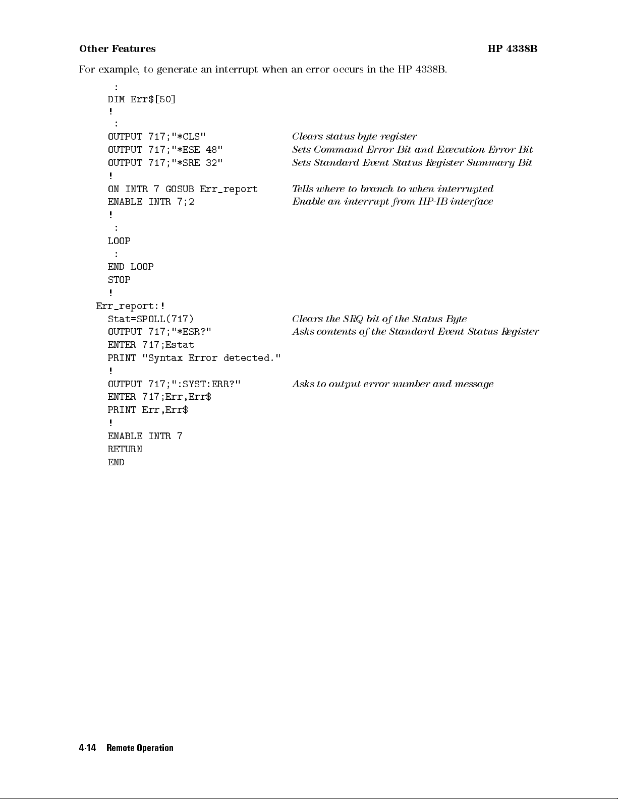
Other Features HP 4338B
For example, to generate an interrupt when an error occurs in the HP 4338B.
:
DIM Err$[50]
!
:
OUTPUT 717;"*CLS"
OUTPUT 717;"*ESE 48"
OUTPUT 717;"*SRE 32"
Clears status byte register
Sets Command Error Bit and Execution Error Bit
Sets Standard Event Status Register Summary Bit
!
ON INTR 7 GOSUB Err_report
ENABLE INTR 7;2
Tells where to branch to when interrupted
Enable an interrupt from HP-IB interface
!
:
LOOP
:
END LOOP
STOP
!
Err_report:!
Stat=SPOLL(717)
OUTPUT 717;"*ESR?"
Clears the SRQ bit of the Status Byte
Asks contents of the Standard Event Status Register
ENTER 717;Estat
PRINT "Syntax Error detected."
!
OUTPUT 717;":SYST:ERR?"
Asks to output error number and message
ENTER 717;Err,Err$
PRINT Err,Err$
!
ENABLE INTR 7
RETURN
END
4-14 Remote Operation
Page 94

HP 4338B If You Have a Problem
If You Have a Problem
Check all HP-IB addresses and connections; most HP-IB problems are caused by an incorrect
address and bad or loose HP-IB cables.
If the HP 4338B Hangs Up When You Send
Send the device clear command to the HP 4338B.
For example,
CLEAR(717)
ABORt
Command
Remote Operation 4-15
Page 95

Page 96

HP-IB Reference
Introduction
This chapter provides the reference for the HP-IB commands used to control the HP 4338B in
the HP-IB remote mode.
HP-IB Commands
Status Reporting Structure
Trigger System
Data Transfer Format
5
The HP 4338B can be operated using the Hewlett-Packard Interface Bus(
corresponds to the Standard Commands for Programmable Instruments(
hp-ib
). HP-IB
scpi
). SCPI is the
instrument command language for controlling instrument that goes beyond IEEE 488.2 to
address a wide variety of instrument functions in a standard manner
.
HP-IB Commands
Commands can be separated into two groups: common commands and subsystem commands
.
Common Commands
Common commands are generally not measurement related, but are used to manage macros
,
status registers, synchronization, and data storage. All common commands begin with an
asterisk. Common commands are dened in the IEEE 488.2 standard.
Common Commands
*CLS
*ESE
*ESE?
*ESR?
*IDN?
*LRN?
<
numeric value
>
*OPC
*OPC?
*OPT?
*RCL
*RST
*SAV
<
numeric value
<
numeric value
*SRE
<
numeric value
>
*SRE?
*STB?
>
*TRG
*TST?
>
*WAI
Subsystem Commands
Subsystem commands include all measurement functions and some general purpose functions.
Each subsystem is a set of commands that roughly corresponds to a functional block inside the
instrument. For example, the SOURce subsystem contains commands for signal generation,
while the STATus subsystem contains commands for accessing status registers.
Subsystem commands have a hierarchical structure, called a
several key words separated by a colon between each word.
command tree
, which consist of
HP-IB Reference 5-1
Page 97
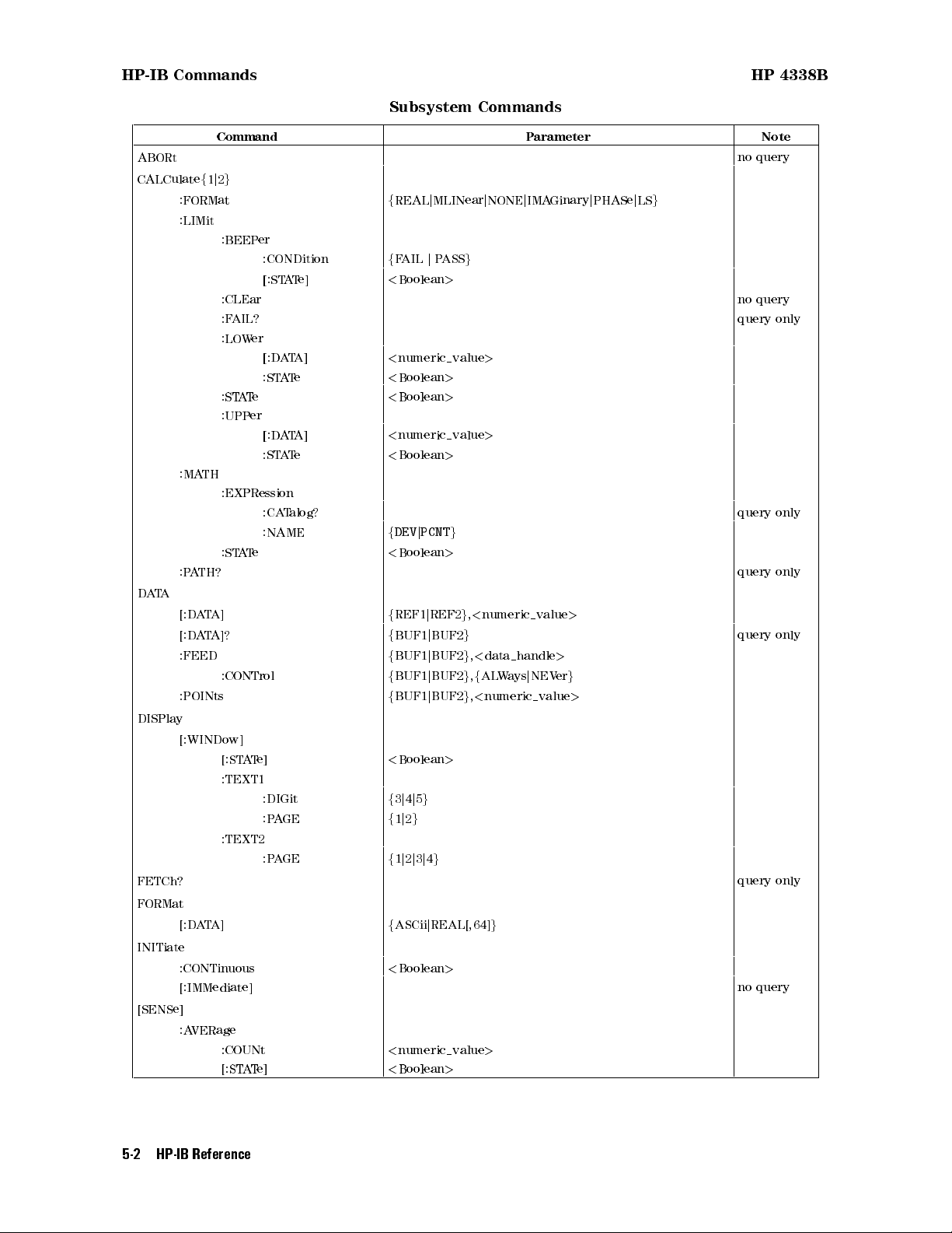
HP-IB Commands HP 4338B
Subsystem Commands
Command Parameter Note
ABORt no query
CALCulatef1j2
:FORMat
g
f
REALjMLINearjNONEjIMAGinaryjPHASejLS
g
:LIMit
:BEEPer
:CONDition
[:STATe]
f
FAILjPASS
<
Boolean
g
>
:CLEar no query
:FAIL? query only
:LOWer
[:DATA]
:STATe
:STATe
<
numeric value
<
Boolean
>
<
Boolean
>
>
:UPPer
[:DATA]
:STATe
<
numeric value
<
Boolean
>
>
:MATH
:EXPRession
:CATalog? query only
:NAME
:STATe
f
DEVjPCNT
<
Boolean
g
>
:PATH? query only
DATA
[:DATA]
[:DATA]?
:FEED
:CONTrol
:POINts
f
REF1jREF2g,<numeric value
f
BUF1jBUF2
f
BUF1jBUF2g,<data handle
f
BUF1jBUF2g,fALWaysjNEVer
f
BUF1jBUF2g,<numeric value
g
>
query only
>
g
>
DISPlay
[:WINDow]
[:STATe]
<
Boolean
>
:TEXT1
:DIGit
:PAGE
f3j4j5g
f1j2g
:TEXT2
:PAGE
f1j2j3j4g
FETCh? query only
FORMat
[:DATA]
f
ASCiijREAL[,64]
g
INITiate
:CONTinuous
<
Boolean
>
[:IMMediate] no query
[SENSe]
:AVERage
:COUNt
[:STATe]
<
numeric value
<
Boolean
>
>
5-2 HP-IB Reference
Page 98

HP 4338B HP-IB Commands
Subsystem Commands (continued)
Command Parameter Note
[SENSe] (continued)
:CORRection
:COLLect
[:ACQuire] STANdard2
:METHod REFL1
:DATA? STANdard2
[:STATe]
<
Boolean
>
:FIMPedance
:APERture
<
numeric value>[MSjS]
:CONTact
:VERify
<
Boolean
>
:RANGe
:AUTO
[:UPPer]
:FUNCtion
<
Boolean
>
<
numeric value>[MOHMjOHMjKOHM]
<
sensor function
>
SOURce
:CURRent
[:LEVel]
[:IMMediate]
[:AMPLitude]<numeric value>[UAjMA]
:AUTO<Boolean
>
STATus
:OPERation
:CONDition? query only
:ENABle
<
numeric value
>
[:EVENt]? query only
:PRESet no query
:QUEStionable
:CONDition? query only
:ENABle
<
numeric value
>
[:EVENt]? query only
SYSTem
:BEEPer
[:IMMediate] no query
:STATe
<
Boolean
>
:ERRor? query only
:KLOCk
:LFRequency
<
Boolean
>
<
numeric value
>
:PRESet
:VERSion? query only
TRIGger
[:SEQuence1]
:DELay
<
numeric value>[MSjS]
[:IMMediate] no query
:SOURce
f
BUSjEXTernaljINTernaljMANual
g
:SEQuence2
:DELay
<
numeric value>[MSjS]
HP-IB Reference 5-3
Page 99

Subsystem Command Tree HP 4338B
Subsystem Command Tree
Top of the subsystem command tree is called the
the low-level commands, you must specify a particular
specify a DOS le directory path. After Power ON or after
root command
path
just like you would for example
*RST
, or simply the
root
.To reach
, the current path is set to the
root. The path settings are changed as follows:
Message Terminator
A message terminator, such as
<new line>
character, sets the current
path to the root.
Colon (:)
When a colon is placed between two command mnemonics, the colon
moves the current path down one level on the command tree. When
the colon is the rst character of a command, it species the following
command mnemonic is a root-level command.
Semicolon (;)
A semicolon separates two commands in the same message without
changing the current path.
Common commands, such as
*RST
, are not part of any subsystem. The HP 4338B interprets
them in the same way, regardless of the current path setting.
Figure 5-1 shows examples of how to use the colon and semicolon to navigate eciently
through the command tree.
Figure 5-1. Proper Use of the Colon and Semicolon
In Figure 5-1, notice how proper use of the semicolon can save typing. Sending this message:
:AA:BB:EE; FF; GG
Is the same as sending these three messages:
:AA:BB:EE
:AA:BB:FF
:AA:BB:GG
5-4 HP-IB Reference
Page 100

HP 4338B Program Message Syntax
Program Message Syntax
This section provides an example of constructing a SCPI program message. A program message
is the message sent from a computer to an instrument. Program messages consist of commands
combined with appropriate punctuation and program message terminators.
Case
Letter case (upper and lower) is ignored.
Program Message Terminator
A program message must end with one of the three
<new line>,<^END>
,or
<new line><^END>.<^END>
interface at the same time the preceding data byte is sent. For example,HPBASIC
program message terminators
,
means that EOI is asserted on the HP-IB
OUTPUT
statement automatically sends a message terminator after the last data byte is sent. If you are
using a PC, you can usually congure your system to send whatever terminator you specify.
Subsystem Command Syntax
Subsystem command consists of the level mnemonics which are separated with colons
example, command form of
APERture
under [
SENSe]:FIMPedance
subsystem becomes as
.For
follows:
:FIMPedance:APERture
Abbreviated mnemonics are also available for command headers. In the above example,
:FIMP:APER
is available.
Common Command Syntax
Common commands do not have a hierarchical structure
. They are just sent as follows:
*CLS
Parameters
There must be a
<space>
between the last command mnemonic and the rst parameter in a
subsystem command.
:FIMP:APERtparameter
t
means a space (ASCII character (decimal 32)) is inserted here
.
If you send more than one parameter with a single command, each parameter must be
separated by a comma. For example,
:POINts
command of
DATA
subsystem is followed by two
parameters as follows:
:DATA:POINtparameter,parameter
Parameter Types
SCPI denes dierent data formats for use in program messages and query responses. The
HP 4338B accepts commands and parameters in various formats and responses a particular
query in a predened and rigid format. Each command reference contains information about
available parameter types for the individual commands.
<
numeric value>is used in both common commands and subsystem commands
<
numeric value>represents numeric parameter as follows:
.
HP-IB Reference 5-5
 Loading...