

Page 1

TB 9-6625-086-35
Change 2
DEPARTMENT OF THE ARMY TECHNICAL BULLETIN
CALIBRATION PROCEDURE FOR
POWER METER, HEWLETT-PACKARD,
MODELS 431B AND 431C (AN/USM-260)
Headquarters, Department of the Army, Washington, DC
2 August 1985
TB 9-6625-086-35, 12 December 1975, is changed as follows:
Page 1, paragraph 2. In lines 4 and 5, change “TM 38-750” to read “750-25.”
Paragraph 3. In lines 7 and 8, changes address to read “Commander, US Army
TMDE Support Group, ATTN: AMXTM-LPP, Redstone Arsenal, AL 35898-5400.”
Page 7, paragraph 12a(2) is superseded as follows;
(2) Set resistance decade (A7) to 10 kΩ. This 10 kΩ value can be decreased as
necessary to obtain full-scale indication on TI.
Page 9, paragraph 15b is superseded as follows:
b. When all parameters are within tolerance, annotate and affix DA Label 80 (US
Army Calibration Instrument). When the TI receives limited or special calibration,
annotate and affix DA Label 163 (US Army Limited or Special Calibration). When the TI
cannot be adjusted within tolerance, repair the TI in accordance with the maintenance
manual. When repair is delayed for any reason or the TI cannot be repaired with local
resources, annotate and affix DA Form 2417 (US Army Calibration System Rejected
Instrument) and inform the owner/user accordingly in accordance with TB 750-25.
By Order of the Secretary of the Army:
JOHN A. WICKHAM, JR.
General, United States Army
Chief of Staff
Official:
DON J. DELANDRO
Brigadier General, United States Army
The Adjutant General
Distribution:
To be distributed in accordance with DA Form 12-34C, Block No. 319, requirements for
calibration publications.
US GOVERNMENT PRINTING OFFICE: 1985 - - 544-007/20156 Region #4
PIN: 010318-002
Page 2
TB 9-6625-086-35
DEPARTMENT OF THE ARMY TECHNICAL BULLETIN
CALIBRATION PROCEDURE FOR
POWER METER, HEWLETT-PACKARD
MODELS 431B AND 431C
(AN/USM-260)
Headquarters, Department of the Army, Washington, DC
29 August 1977
TB 9-6625-086-35, 12 December 1975, is changed as follows:
Page 5, paragraph 10a(3) is superseded as follows:
(3) Position the TI RANGE switch to the .01 MW position and adjust the zero
controls for 0.00 V dc on the dc voltmeter.
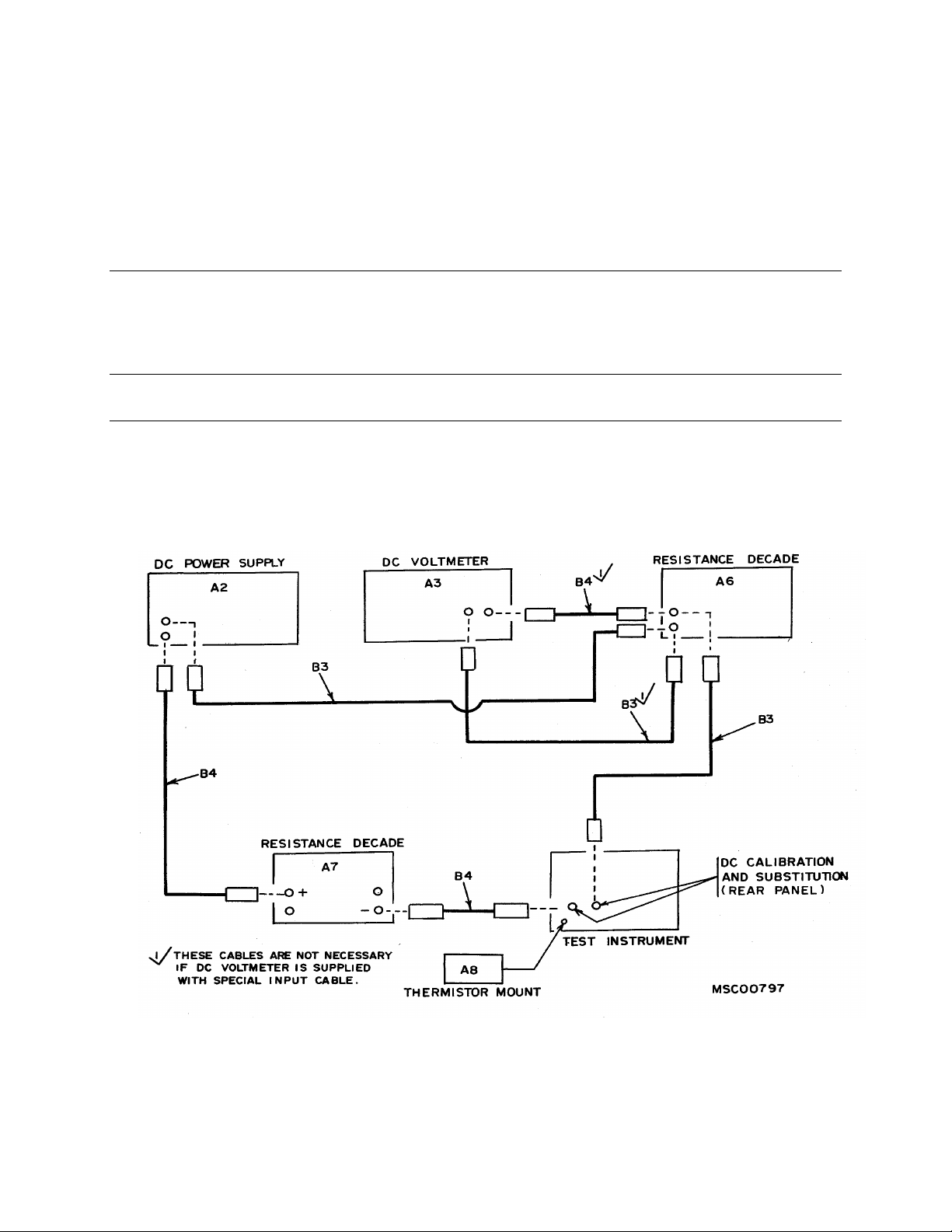
Page 8, figure 4 is superseded as follows:
Change 1
Figure 4. Range and tracking check without power meter calibrator.
Page 3

By Order of the Secretary of the Army:
BERNARD W. ROGERS
General, United States Army
Chief of Staff
Official:
PAUL T. SMITH
Major General, United States Army
The Adjutant General
Distribution:
To be distributed in accordance with DA Form 12-34A, Requirements for Calibration
Procedures.
U.S. GOVERNMENT PRINTING OFFICE: 1977-765010/180
PIN NO: 010318-001
Page 4

TB 9-6625-086-35
DEPARTMENT OF THE ARMY TECHNICAL BULLETIN
CALIBRATION PROCEDURE FOR
POWER METER, HEWLETT-PACKARD
MODELS 431B AND 431C (AN/USM-260)
Headquarters, Department of the Army, Washington, DC
12 December 1975
♦♦REPORTING OF ERRORS♦♦
You can help improve this publication by calling attention to errors and by
recommending improvements and stating your reasons for the
recommendations. Your letter or DA Form 2028, Recommended Changes to
Publications, should be mailed directly to Commander, U.S. Army Aviation and
Missile Command, ATTN: AMSAM-TMD-EP, Redstone Arsenal, AL 35898-5000.
FAX to DSN 788-2313 (commercial 256-842-2313). A reply will be furnished
directly to you.
Paragraph Page
SECTION I. IDENTIFICATION AND DESCRIPTION
Test instrument identification............................ 1 2
Calibration data card, DA Form 2416................ 2 2
Calibration description....................................... 3 2
II. EQUIPMENT REQUIREMENTS
Equipment required ........................................... 4 2
Accessories required........................................... 5 3
III. PRELIMINARY OPERATIONS
Preliminary instructions .................................... 6 4
Equipment Setup................................................ 7 4
IV. CALIBRATION PROCESS
Coarse null.......................................................... 8 5
Zero and vernier................................................. 9 7
Range and tracking check with power meter
calibrator.......................................................... 10 7
Range and tracking without power meter
calibrator.......................................................... 11 9
Oscillator frequency............................................ 12 11
Power supply ...................................................... 13 12
Final procedure................................................... 14 13
_____________
*This bulletin supersedes TB 9-6625-086--35, 31 December 1974.
Page 5

Page 6

TB 9-6625-086-35
SECTION I
IDENTIFICATION AND DESCRIPTION
1. Test Instrument Identification. This bulletin provides instructions for the
calibration of Power Meter, Hewlett-Packard Models 431B and 431C (AN/USM-260). The
manufacturer's instruction manual was used as the prime data source in compiling these
instructions. The equipment being calibrated will be referred to as the "TI" (test
instrument) throughout this bulletin.
a. Model Variations. Variations among models are described in text.
b. Time and Technique. The time required for this calibration is approximately 1
hour, using the microwave or dc low technique.
2. Calibration Data Card, DA Form 2416. Forms, records, and reports required for
calibration personnel at all levels are prescribed by TB 750-25. DA Form 2416 must be
annotated in accordance with T750-25 for each calibration performed.
3. Calibration Description. TI parameters and performance specifications which
pertain to this calibration are listed in table 1.
Table 1. Calibration Description
Test instrument parameters Performance specifications
Zero carryover Less than 0.5% of FS when zeroed on most sensitive scale
Range 0.01 to 10 mw in 7 ranges: -20 to +10 dBm in 5 -dBm steps
Accuracy Model 431C
From +20°C to +35°C - .01 mw range, ±2% of FS, .03 mw range, ±1.5% of
FS; all other ranges, ±1% of FS.
From 0°C to +55°C, ±3% of FS on all ranges.
Model 431B
From +20°C to +35°C, ±3% of FS on all ranges.
From 0°C to +55°C, ±5% of FS on all ranges.
SECTION II
EQUIPMENT REQUIREMENTS
4. Equipment Required. Table 2 identifies the specific equipment used in this
calibration procedure. This equipment is issued with the secondary transfer calibration
standards sets 6695-00-621-7877 and 4931-00-525-8175 and maintenance calibration
shelter AN/TSM-55. Alternate items may be used by the calibrating activity when the
equipment listed in table 2 is not available. The items selected must be verified to perform
satisfactorily prior to use and must bear evidence of current calibration. The equipment
must meet or exceed the minimum use specifications listed in table 2. The accuracies listed
in table 2 provide a four-to-one accuracy ratio between the standard and TI. Where the
four-to-one ratio cannot be met, the actual accuracy of the equipment selected is shown in
parenthesis.
2
Page 7

TB 9-6625-086-35
Transfer
(6625-00-621-
General Radio,
Dana, Model
Systron-
Hewlett-
Hewlett-
478A
X486A
5. Accessories Required. The accessories listed in table 3 are issued with the secondary
transfer calibration standards sets 6695-00-621-7877 and 4931-00-525-8175 and
maintenance calibration shelter AN/TSM-55. When necessary, these items may be
substituted by equivalent items unless specifically prohibited.
Table 2. Minimum Specifications of Equipment Required
Minimum use
Item Common name
specifications
A1 AUTOTRANSFORMER Range:105 to 125 V ac
A2 DC POWER SUPPLY
1
Range:0 to 25 vdc TS 2734/U John Fluke,
A3 DC VOLTMETER Range:0 5 to 25 vdc
Accuracy: ±0.05%
A4 FREQUENCY
COUNTER
Range:9950 to 10,275
Hz
Accuracy: ±0.025%
A5 POWER METER
CALIBRATOR
A6 RESISTANCE
1
DECADE
A7 RESISTANCE
1
DECADE
A8 THERMISTOR
MOUNT
Range:0.01 to 10 mw
Accuracy: ±0.25%
Range:1 k ohm
Accuracy: ±0.05%
Range:10 k ohm
Accuracy: Nominal
Range:10 MHz to 12.4
GHz
Accuracy: ±5%
10 MHz to 10 GHz
8.2 to 12.4 GHz
1
Not used if power meter calibrator (A5) is available.
7877)
Model
W10MT3AS3
(7910809)
5703-S-2127
(7912606)
Donner
Model 1037M (7910823)
(P/O
7910628)
Packard
8402B
(7911026)
Packard,
Models
(7910461)
(7910460)
Manufacturer and model
(part number)
Maintenance
(AN/TSM-55)
Maintenance
(4931-00-525-
8175)
TS 510/U General Radio,
Model
W10MT3AS3
(7910809)
Model 760A
John Fluke,
Model 882AB
(TS-2843/U)
AN/USM-
257A
Hewlett-
Packard, Model
3490A
Hewlett-
Packard, Model
5245L
AN/USM-317
Biddle-Gray,
Model 71-631
(7910328)
CMC, Model
240C (7907234)
MX-7772/U Hewlett-
Packard, Model
478A (7910461)
Hewlett-
Packard,
Model X486A
Table 3. Accessories Required
Item Common name Description and Part Number
B1 Adapter Double banana jack to BNC plug (7909401)
B2 Adapter Double banana jack to phone plug (7907566)
B3 Cable
B4 Cable
1
1
24-in., single banana plug terminations (red) (7907497)
24-in., single banana plug terminations (black) (7907498)
B5 Cable 36-in., BNC plug to alligator clips (7909410)
B6 Termination 50-ohm, N jack (374 NM)
1
Three required when using maintenance standard set 4931-00-525-8175.
3
Page 8

TB 9-6625-086-35
SECTION III
PRELIMINARY OPERATIONS
6. Preliminary Instructions
a. The instructions outlined in this section are preparatory to the calibration process.
Personnel should become familiar with the entire bulletin before beginning the calibration.
b. Items of equipment used in this procedure are referenced within the text by common
name and item identification number as listed in tables 2 and 3. For the identification of
equipment referenced by item numbers prefixed with A, see table 2, and for prefix B, see
table 3.
WARNING
HIGH VOLTAGE is used during the performance of this
calibration. DEATH ON CONTACT may result if personnel
fail to observe safety precautions.
7. Equipment Setup
a. Connect autotransformer (A1) to the power source and adjust for 115 volts ac.
CAUTION
Throughout this procedure, make sure the TI is deenergized
while connecting or disconnecting a thermistor mount or when
repositioning the MOUNT RES switch.
b. Connect the TI to autotransformer.
c. Adjust the TI mechanical zero setscrew clockwise until the pointer is left of zero,
moving up scale. Stop when the pointer indicates zero.
NOTE
If pointer overshoots zero indication during adjustment, repeat
c above.
d. Adjust the zero setscrew approximately 15 degrees counterclockwise to free the
setscrew from the meter movement.
e. If the pointer moves while freeing the setscrew, repeat c and d above.
f. Connect 200-ohm thermistor mount (A8) to the TI, using cable furnished with the TI
and terminate the mount with coaxial termination (B6).
g. On model 431C, set the CALIB FACTOR PERCENT switch to 100 and leave it in
this position for the remainder of the procedure.
4
Page 9

Unless otherwise specified, verify the results of each test and
take corrective action whenever the test requirement is not
met before continuing with the calibration.
When indications specified in paragraphs 8 through 11 are not
within tolerance, perform the oscillator frequency check in
paragraph 12 and the power supply check in paragraph 13
before making adjustments. Do not perform the procedures in
paragraphs 12 and 13 if all other parameters are within
tolerance.
Remove top and side covers from the TI only for adjustment.
When adjustment is completed, reinstall the covers.
8. Coarse Null
TB 9-6625-086-35
SECTION IV
CALIBRATION PROCESS
NOTE
NOTE
NOTE
a. Performance Check
(1) Position the TI RANGE switch to the .01 MW position.
(2) Adjust the TI ZERO controls for a 25 to 75 percent indication on the TI meter.
(3) Turn the RANGE switch to NULL.
(4) Adjust the NULL, control for minimum indication on the TI meter.
(5) Repeat (2) through (4) above until the TI meter pointer is within the NULL
region. If the meter pointer does not indicate within the NULL region, perform b below.
NOTE
During maintenance calibration, if a 100-ohm thermistor
mount is not available, disregard (6) through (8) below.
(6) Connect 100-ohm thermistor mount (A8) to the TI.
(7) Set the TI MOUNT RES switch to 100.
(8) Repeat (2) through (5) above.
b. Adjustments. On model 431C, adjust L1 (fig. 1)(L102, fig. 2 on model 431B) for
null on the TI.
5
Page 10

TB 9-6625-086-35
Figure 1. Right interior view - model 431C..
Figure 2. Top interior view - model 431B.
6
Page 11

TB 9-6625-086-35
9. Zero and Vernier
a. Performance Check
(1) On model 431C, connect dc voltmeter (A3) to the TI DVM output (rear panel)
using adapter (B1) and if necessary cables (B3) and (B4).
(2) On model 431B, connect resistance decade (A6)(set at 1000 ohms) to the TI
RECORDER output, using adapter (B2) and cables (B3 and B4). Connect the dc voltmeter
to the same terminals of the resistance decade, using cables (B3 and B4) if necessary.
(3) Position the TI RANGE switch to the .01 MW position and adjust the zero
controls for 0.00 volt dc on the dc voltmeter.
(4) Turn the TI RANGE switch to .03-, .1-, .3-, l-, 3-, and 10-MW positions while
observing dc voltmeter. If the dc voltmeter does not indicate between -0.01 and +0.01 volt
in each position of the RANGE switch, perform b below.
b. Adjustments. On model 431C, adjust R37 (fig. 1) for 0.00 ±.01 volt on the dc
voltmeter at each RANGE switch setting. No adjustment can be made on model 431B.
NOTE
Perform paragraph 10 below if power meter calibrator (A5) is
available as a standard. If a power meter calibrator is not
available, omit paragraph 10 and proceed to paragraph 11.
10. Range and Tracking Check with Power Meter Calibrator
a. Performance Check
(1) Connect 200-ohm thermistor mount (A8) to the TI.
(2) Position the controls of power calibrator (A5) as follows:
(a) FUNCTION switch to CURRENT OFF.
(b) MOUNT RESISTANCE to correspond with the resistance of the thermistor
mount being used.
(c) CURRENT and VERNIER fully counterclockwise.
(3) Connect the POWER METER terminals of the power meter calibrator to the DC
CALIBRATION terminals (rear panel) of the TI, using cables (B3 and B4).
(4) Set the TI MOUNT RES switch to 200Ω.
(5) Set the TI RANGE switch to the .01 MW position and null and zero the meter.
7
Page 12

TB 9-6625-086-35
(6) Position the controls of the power meter calibrator as follows:
(a) RANGE (MW) switch to .01.
(b) FUNCTION switch to CAL.
NOTE
After each change in position of TI RANGE switch, turn the
FUNCTION switch of power meter calibrator to the CURRENT
OFF position and adjust the TI zero controls for a zero
indication.
(7) Turn the TI and power meter calibrator RANGE switches to the settings listed
in table 4. If the indications are not within limits specified, perform b below.
Table 4. Range and Trucking Performance Check (with Power Meter Calibrator)
Test Instrument Indications (mw)
Power Meter
Test Instrument
RANGE switch RANGE (MW) Min Max 200-Ohm 100-Ohm
settings switch settings Mount Mount
.01 .01 0.0098
.03 .03 0.0295
.1 .1 0.099
.3 .3 0.297
1 1 0.990
3 3 2.970
10 10 9.900
1
10
10 6 5.9
10 4 3.9
10 2 1.9
Calibrator
8 7.9
(Readings for Model 431B
are in parenthesis)
0.0102
(0.0097)
(0.0291)
(0.097)
(0.291)
(0.970)
(2.910)
(9.700)
(7.7)
(5.7)
(3.7)
(1.7)
(0.0103)
0.0305
(0.0309)
0.101
(0.103)
0.303
(0.309)
1.010
(1.030)
3.030
(3.090)
10.100
(10.300)
8.1
(8.3)
6.1
(6.3)
4.1
(4.3)
2.1
(2.3)
Adjustments for Model
431C (fig. 3)
R14 R1
R13 R2
R12 R3
R11 R4
R10 R5
R9 R6
R8 R7
8
Page 13

TB 9-6625-086-35
(8) Repeat (1) through (7) above with 100 ohm thermistor mount (A8) connected to
the TI and with the TI MOUNT RES switch set to 100Ω.
(9) Reconnect the 200-ohm thermistor mount to the TI and set the MOUNT RES to
200Ω.
b. Adjustments. Adjust the appropriate potentiometer, R1 through R14 (fig. 3), to the
mean value. No adjustment can be made on model 431B.
Figure 3. Left interior view, model 431C.
11. Range and Tracking Check Without Power Calibrator
a. Performance Check
(1) Connect the equipment as shown in figure 4.
(2) Set resistance decade (A7) to 10 kΩ. This 10 kΩ value can be decreased as
necessary to obtain full scale indication on TI.
(3) Set resistance decade (A6) to 1000 ohms.
9
Page 14

TB 9-6625-086-35
(4) Set the TI MOUNT RES switch to agree with the thermistor mount (A8) being
used.
(5) Set the TI RANGE switch to .01 MW and null and zero the meter.
(6) Adjust dc power supply (A2) for a full-scale (.01 mw) indication on the TI. If dc
voltmeter (A3) indication is not within the limits specified in table 5, perform b below.
Figure 4. Range and tracking check without power meter calibrator.
Table 5. Range and tracking Performance Check (Without Power Meter Calibrator)
Test Test Dc Voltmeter Indications (vdc) (Readings Adjustments for Model
Instrument Instrument for Model 431B are in Parenthesis) 431C (fig. 3)
Switch Indication 200-Ohm Mount 100-Ohm Mount 200-Ohm 100-Ohm
Settings Min Max Min Max Mount Mount
.01 .01 .438
(.434)
.03 .03 .763
(.752)
.1 .1 1.40
(1.37)
.3 .3 2.43
(2.38)
1 1 4.43
(4.34)
.456
(.460)
.787
(.798)
1.42
(1.45)
2.47
(2.52)
4.51
(4.60)
.619
(.613)
1.08
(1.06)
1.98
(1.94)
3.43
(3.36)
6.26
(6.13)
.645
(.651)
1.12
(1.13)
2.02
(2.06)
3.49
(3.56)
6.38
(6.51)
R14 R1
R13 R2
R12 R3
R11 R4
R10 R5
10
Page 15

TB 9-6625-086-35
Table 5. Range and tracking Performance Check (Without Power Meter Calibrator) - Continued
Test Test Dc Voltmeter Indications (vdc) (Readings Adjustments for Model
Instrument Instrument for Model 431B are in Parenthesis) 431C (fig. 3)
Switch Indication 200-Ohm Mount 100-Ohm Mount 200-Ohm 100-Ohm
Settings Min Max Min Max Mount Mount
3 3 7.67
(7.52)
10 10 14.00
(13.7)
10 8 12.52
(12.3)
10 6 10.84
(10.6)
10 4 8.85
(8.67)
10 2 6.26
(6.13)
7.83
(7.98)
14.28
(14.6)
12.78
(13.0)
11.06
(11.3)
9.03
(9.21)
6.38
(6.51)
10.84
(10.6)
19.80
(19.4)
17.71
(17.4)
15.34
(15.0)
12.52
(12.3)
8.85
(8.67)
11.06
(11.3)
20.20
(20.6)
18.07
(18.4)
15.64
(16.0)
12.78
(13.0)
9.03
(9.21)
R9 R6
R8 R7
NOTE
Each time the TI RANGE switch is changed, turn the dc power
supply off and zero the TI meter.
(7) Repeat the technique in (5) and (6) above for the remaining positions of the TI
RANGE switch. If both a 200-ohm and 100-ohm thermistor mount is available, perform (1)
through (6) above for both mounts.
b. Adjustments. Adjust R1 through R14 (fig. 3) as appropriate for model 431C. No
adjustment can be made on model 431B.
12. Oscillator Frequency
NOTE
Do not perform the oscillator frequency check if all parameters
in paragraphs 8 through 11 above are within tolerance.
a. Performance Check
(1) On model 431C, connect frequency counter (A4) to the positive end of C18 (fig. 1)
and ground, using cable (B4). On model 431B, connect the counter to the positive end of
C125 (fig. 2) and ground.
(2) Connect 200-ohm thermistor mount (A8) to the TI and terminate the mount
with termination (B6).
(3) Set the TI MOUNT RES switch to 200Ω.
(4) If the frequency counter does not indicate between 9,990 and 10,010 Hz for
model 431C, perform b(1) below. For model 431B, if the frequency counter does not
indicate between 10,025 and 10,275 Hz, perform b(2) below.
11
Page 16

TB 9-6625-086-35
Perform (5) through (7) below if the TI is to be used with a 100-
ohm thermistor mount.
(5) Disconnect the 200-ohm thermistor mount from the TI.
(6) Connect 100-ohm thermistor mount (A8) to the TI and turn the MOUNT RES
switch to 100Ω.
(7) The frequency counter will indicate between 9,950 and 10,050 Hz.
b. Adjustments
(1) Adjust L2 (fig. 1) on model 431C.
(2) Adjust L101 (fig. 2) on model 431B.
13. Power Supply
a. Performance Check
Do not perform the power supply check if all other parameters
are within tolerance.
NOTE
NOTE
(1) Connect dc voltmeter (A3) to pin W of terminal board XA2 (fig. 5) and ground.
For model 431B, connect the voltmeter to the negative end of C6 (fig. 2) and ground.
Figure 5. Top internal view-model 431C.
12
Page 17

TB 9-6625-086-35
(2) If the dc voltmeter does not indicate between -17.98 and -18.02 volts dc, perform
b below.
(3) Vary the output of autotransformer (A1) between 105 and 125 volts ac. The dc
voltmeter indication will remain within the limits specified in (2) above.
(4) Adjust the autotransformer for a 115-volt ac output.
b. Adjustments. Adjust R36 (fig. 3) for model 431C or R13 (fig. 2) for model 431B.
14. Final Procedure
a. Deenergize and disconnect all equipment and replace TI protective cover.
b. When all parameters are within tolerance, annotate and affix DA Label 80 (US
Army Calibrated Instrument). When the TI receives limited or special calibration,
annotate and affix DA Label 163 (US Army Limited or Special Calibration). When the TI
cannot be adjusted within tolerance, repair the TI in accordance with the maintenance
manual. When repair is delayed for any reason or the TI cannot be repaired with local
resources, annotate and affix DA Form 2417 (US Army Calibration System Rejected
Instrument) and inform the owner/user accordingly in accordance with TB 750-25.
13
Page 18

TB 9-6625-086-35
By Order of the Secretary of the Army:
FRED C. WEYAND
General, United States Army
Chief Of Staff
Official:
PAUL T. SMITH
Major General, United States Army
The Adjutant General
Distribution:
To be distributed in accordance with DA Form 12-34C, Block No. 319, requirements for
calibration publications.
US GOVERNMENT PRINTING OFFICE: 1975 - - 641-219-5023
PIN: 010318-000
 Loading...