

Page 1

TM 11-6625-1538-15
DEPARTMENT OF THE ARMY TECHNICAL MANUAL
OPERATOR, ORGANIZATIONAL, DS, GS, AND DEPOT
MAINTENANCE MANUAL
HEWLETT-PACKARD AC VOLTMETER AN/USM-265
(MODEL 400EL02) NSN 6625-00-935-4294
ME-459 (MODEL 400EL) NSN 6625-00-229-0457
ME-465 (MODEL 400E) NSN 6625-00-995-7716
This copy is a reprint which includes current
pages from Changes 1 and 2.
HEADQUARTERS, DEPARTMENT OF THE ARMY
MAY 1967
Page 2

WARNING
DANGEROUS VOLTAGES
EXIST IN THIS EQUIPMENT
Be careful when working on the power supplies and
their circuits, or on the 230-or 115–volt ac line
connections.
DO NOT TAKE CHANCES!
Page 3

TM 11-6625-1538-15
C2
CHANGE
HEADQUARTERS
DEPARTMENT OF THE ARMY
NO. 2
Washington, DC, 15 December 1983
OPERATOR’S, ORGANIZATIONAL, DIRECT SUPPORT,
GENERAL SUPPORT, AND DEPOT MAINTENANCE
MANUAL FOR
HEWLETT-PACKARD AC VOLTMETER AN/USM-265
(MODEL 400EL02) NSN 6625-00-935-4294
ME-459 (MODEL 400EL) NSN 6625-00-229-0457
ME-465 (MODEL 400E) NSN 6625-00-995-7716
TM 11-6625-1538-15, 11 May 1987, is changed as follows:
1. New or added material is indicated by a vertical bar in the margin of the page.
2. Added or revised illustrations are indicated by a vertical bar adjacent to the illustration identification number.
3. Remove old pages and insert new pages as indicated below.
Remove Pages
Insert Pages
i and ii
10.1 and 10.2
5-1 and 5-2
4. File this change sheet in front of the publication for reference purposes.
i and ii
10.1/(10.2 blank)
5-1 through 5-2.2
A-1/(A-2 blank)
Page 4

By Order of the Secretary of the Army:
Official:
ROBERT M. JOYCE
Major General, United States Army
The Adjutant General
DISTRIBUTION:
To be distributed in accordance with DA Form 12-34B, requirements for
TMDE.
JOHN A. WICKHAM JR.
General, United States Army
Chief of Staff
Page 5

TM 11-6625-1538-15
C1
CHANGE
HEADQUARTERS
DEPARTMENT OF THE ARMY
No. 1
WASHINGTON,DC, 27 December 1979
Operator’s, Organizational, Direct Support,
General Support, and Depot Maintenance Manual
For
HEWLETT-PACKARD AC VOLTMETER AN/USM-265
(MODEL 400EL02) NSN 6625-00-935-4294
ME-459 (MODEL 400EL) NSN 6625-00-229-0457
ME-465 (MODEL 400E) NSN 6625-00-995-7716
TM 11-6625-1538-15, 11 May 1967, is changed as follows:
1. Title is changed as indicated above.
2. A vertical bar appears opposite changed material.
3. Remove and insert pages as indicated in the page list below:
Remove
iii and 1-0
None . . . . . . . . . . . . . . . . . . . . . . . . .
1-0.1
None . . . . . . . . . . . . . . . . . . . . . . .
4. File this change sheet in front of the manual for reference purposes.
By Order of the Secretary of the Army:
. . . . . . . . . . . . . . . . . . . . . . . . . . . . . . . . . . . . . . . . . . . . . . . . . . . . . . . . . . . . . . . .
. . . . . . . . . . . . . . . . . . . . . . . . . . . . . . . . . . . . . . . . . . .
. . . . . . . . . . . . . . . . . . . . . . . . . . . . . . . .
. . . . . . . . . . . . . . . . . . . . . . . . . . . . . .
. . . . . . . . . . . . . . . . . . . . . . . . . . . . . . . . . . . . .
. . . . . . . . . . . . . . . .
Insert
i and ii
1-0
1-0.1 and 1-0.2
D-1 through D-4
Official:
J. C. PENNINGTON
Major General, United States Army
The Adjutant General
DISTRIBUTION:
Active Army:
HISA (Ft Monmouth) (21) Svc Colleges (1)
USAINSCOM (2) USASIGS (5)
COE (1) USAADS (2)
TSG (1)
USAARENBD (1) USAARMS (2)
DARCOM (1)
TRADOC (2)
OS Maj Comd (4) USAICS (3)
TECOM (2)
USACC (4)
MDW (1)
Armies (2)
Corps (2)
ARNG: None
USAR: None
For explanation of abbreviations used, see AR 310-50.
USAFAS (2)
USAIS (2)
USAES (2)
MAAG (1)
USARMIS (1)
USAERDAA (1)
USAERDAW (1)
Fort Gordon (10)
E. C. MEYER
General, United States Army
Chief of Staff
Fort Carson (5)
Army Dep (1) except
LBAD (14)
SAAD (30)
TOAD (14)
SHAD (3)
Fort Gillem (10)
USA Dep (1)
Sig Sec USA Dep (1)
Fort Richardson (CERCOM Ofc) (2)
Units org under fol TOE:
(2 copies each unit)
29-207
29-610
Page 6

Page 7

This manual contains copyrighted material orginally prepared by the Hewlett-Packard Company.
TM 11-6625-1538-15
TECHNICAL M ANUAL
HEADQUARTERS
DEPARTMENT OF THE ARMY
ASHINGTON , DC, 11 May 1967
TM 11-6625-1538-15
W
OPERATOR’S, ORGANIZATIONAL, DIRECT SUPPORT,
GENERAL SUPPORT, AND DEPOT MAINTENANCE MANUAL
FOR
HEWLETT-PACKARD AC VOLTMETER AN/USM-265
(MODEL 400EL02) NSN 6625-00-935-4294
ME-459 (MODEL 400EL) NSN 6625-00-229-0457
ME-465 (MODEL 400E) NSN 6625-00-995-7716
SECTION I. GENERAL INFORMATION
ECTION II. INSTALLATION . . . . . . . . . . . . . . . . . . . . . . . . . . . . . . . .
S
ECTION III. OPERATING INSTRUCTIONS . . . . . . . . . . . . . . . . . . . . . . . . . . . . . . . . . . . . . . . . . . . . . . . . . . . . . . . . . . . . . .
S
ECTION IV. THEORY OF OPERATION . . . . . . . . . . . . . . . . . . . . . . . . . . . . . . . . . . .
S
SECTION
l-A.l. Scope . . . . . . . . . . . . . . . . . . . . . . . . . . . . . . . . . . . . . . .
lA.2. Consolidated index of Army publications and blank forms.... . . . . . . . . . . . . . . . . . . . . . . . . . . . . .
1A.3. Maintenance Forms, Records, and Reports
lA.4. Reporting Errors and Recommending Improvements . . . . . . . . . . . . . . . . . . . . . . . . . . . . . . . . .
1-A.5. Reporting Equipment Improvement Recommendations (EIR)
l-A.6. Administrative Storge . . . . . . . . . . . . . . . . . . . . . . . . . . . . . . . . . . . . . . . . . . . .
l-A.7. Destruction of Army Electronics Materiel . . . . . . . . . . . . . . . . . . . . . . . . . . . . . . . . . . . .
1-1.
Description . . . . . . . . . . . . . . . . . . . . . . . . . . . . . . . . . . . . . . . . . . . . . . . . . . . . . . . . . . . . . . . . . . . . . . . . . .
1-4.
Options Available . . . . . . . . . . . . . . . . . . . . . . . . . . . . . . . . . . . . . . . . . . . . . . . . . . . . . . . . . . . . . . . . . . .
1-5.
Option 01(400E only) . . . . . . . . . . . . . . . . . . . . . . . . . . . . . . . . . . . . . . . . . . . . . . . . . . . . . . . . . . . . . . .
1-7.
0ption 02 . . . . . . . . . . . . . . . . . . . . . . . . . . . . . . . . . . . . . . . . . . . . . . . . . . . . . . . . . . . . . . . . . . . . . . . . . . .
1-9.
Instrument and manual Identification . . . . . . . . . . . . . . . . . . .
2-1.
Introduction . . . . . . . . . . . . . . . . . . . . . . . . . . . . .
2-3.
Initial Inspection . . . . . . . . . . . . . . . . . . . . . . . . . . . . . . . . . . . . . . . . . . . . . . . . . . . . . . . . . . . . . . . . . . . .
2-5. Power Requirements . . . . . . . . . . . . . . . . . . . . . . . . . . . . . . . . . . . . . . . . . . . . . . . . . . . . . . . . . . . . . . . . ,
2-7.
Grounding Requirements . . . . . . . . . . . . . . . . . . . . . . . . . . . . . . . . . . . . . . . . . . . . . . . . . . . . . . . . .
2-10. Installation . . . . . . . .
2-12.
2-14.
2-16.
2-18. Repackaging for Shipment . . . . . . . . . . . . . . . . . . . . . . . . . . . . . . . . . . . . . . . . . . . . . . . . . . . . . . . . . . .
3-1.
3-4.
3-6. Operating Instructions
3-7.
3-12.
3-14.
4-1.
4-8.
4-9.
4-12.
4-15.
4-20.
4-22. Power Supply . . . . . . . . . . . . . . . . . . . . . . . . . . . . . . . . . . . . . . . . . . . . . . . . . . . . . . . . . . . . . . . . . . . .
Bench Mounting . . . . . . . . . . . . . . . . . . . . . . . . . . . . . . . . . . . . . . . . . . . . . . . . . . . . . . . . . . . . . . . . . .
Rack Mounting . . . . . . . . . . . . . . . . . . . . . . . . . . . . . . . . . . . . . . . . . . . . . . . . . . . . . . . . . . . . . . . . . . . .
Combination Mounting . . . . . . . . . . . . . . . . . . . . . . . . . . . . . . . . . . . . . . . . . . . . . . . . . . . . . . . . . . . .
Introduction . . . . . . . . . . . . . . . . . . . . . . . . . . . . . .
Location of Controls and Indicators . . . . . . . . . . . . .
Standard 400E/EL . . . . . . . . . . . . . . . . . . . . . . . . . . . . . . . . . . . . . . . . . . . . . . . . . . . . . . . . . . . . . . . .
400E with Option 01 . . . . . . . . . . . . . .
400E/EL with Option02 . . . . . . . . . . . . . . . . . . . . . . . . . . . . . . . . . . . . . . . . . . . . . . . . . . . . . . . . . . .
General . . . . . . . . . . . . . . . . . . . . . . . . . . . . . . . . . . . . . . . . . . . . . . . . . . . . . . . . . . . . . . . . . . . . . . . . . . . . .
Schematic Description (See Figure 6-l) . . . . . . . . . . . . . . . . . . . . . . . . . . . . . . . . . . . . . . . . . . . . . . .
Impedance Converter .
Meter Amplifier . . . .
Meter Bridge . . . . . . . . . . . . . . . . . . . . . . . . . . . . . . . . . . . . . . . . . . . . . . . . . . . . . . . . . . . . . . . . . . . . . .
AC Output Circuit . . . . . . . . . . . . . . . . . . . . . . . . . . . . . . . . . . . . . . . . . . . . . . . . . . . . . . . . . . . . . . . . .
. . . . . . . . . . . . . . . . . . . . . . . . . . . . . . . . . . . . . . . . . . . . . . . . . . . . . . . . . . . . . . . . . . . .
. . . . . . . . . . . . . . . . . . . . . . . . . . . . . . . . . . . . . . . . . . . . . . . . . . . . . . . . . . . . . .
. . . . . . . . . . . . . . . . . . . . . . . . . . . . . . . . . . . . . . . . . . . . .
. . . . . . . . . . . . . . . . . . . . . . . . . . . . . . . . . . . . . . . . . . . . . . . . . . . . . . . . . . . .
. . . . . . . . . . . . . . . . . . . . . . . . . . . . . . . . . . . . . . . . . . . . . . . . . . . . . . . . . . . . . . .
V. MAINTENANCE . . . . . . . . . . . . . . . . . . . . . . . . . . . . . . . . . . . . . . . . . . . .
5-1.
Introduction . . . . . . . . . . .
5-3.
Required Equipment . . . . . . . . . . . . . . . . . . . . . . . . . . . . . . . . . . . . . . . . . . . . . . . . . . . . . . . . . . . . . . . .
. . . . . . . . . . . . . . . . . . . . . . . . . .
. . . . . . . . . . . . . . . . . . . . . . . . . . . . . . . . . . . . . . .
. . . . . . . . . . . . . . . . . . . . . . . . . . . . . . . . . . . . . . . . . . .
. . . . . . . . . . . . . . . . . . . . . . . . .
. . . . . . . . .
. . . . . . . . . . . . . . . . . . . . . . . . .
. . . . . . . . . . . . . . . . . . . . . . . . . . . . . . . . . . . . . . . . . .
. . . . . . . . . . . . . . . . . . . . . . . . . . . . . . . . . . . . . . . . . . .
. . . . . . . . . . . . . . . . . . . . . . . . . . . . . . . . . . . . . . .
. . . . . . . . . . . . . . . . . . . . . . . . . . . . . . . . . . . . .
. . . . . . . . . . . . . . . . . . . . . . . . .
. . . . . . . . . . . . . . . . . . . . . . . . .
. . . . . . . . . . . . . . . . . . . . . . . . . . . . . . . .
Page
1-0.1
1-0.1
1-0.1
1-0.1
1-0.1
1-0.1
1-0.1
1-1
1-1
1-1
1-1
1-1
2-1
2-1
2-1
2-1
2-1
2-1
2-1
2-1
2-1
2-1
3-1
3-1
3-1
3-1
3-1
3-2
3-2
4-1
4-1
4-1
4-1
4-2
4-2
4-2
4-2
5-1
5-1
5-1
Change 2
i
Page 8

TM 11-6625-1538-15
5-4.1. Preventive Maintenance
5-4.2. Operator/Crew Preventive Maintenance Checks and Services
5-5.
Mechanical Zero Adjust (400E Only)
5-7.
Performance Checks Accuracy and Frequency Response Test . . . . . . . . . . . . . . . . . . . . . . . . .
5-19.
5-22. Alignment and Calibration Procedure . . . . . . .
5-24.
5-27.
5-29. AC Output Zero
5-31.
SECTION V.
ECTION VI.
S
APPENDIX A.
APPENDIX D.
SECTION I.
5-34. Troubleshooting
5-38. Power Supply
5-40.
5-46.
5-48. Adjustment of Factory Selected Components . . . . . . . . . . . . . . . . . . . . . . . . . . . . . . . . . . . . . . . . .
CIRCUIT DIAGRAMS
6-1.
Introduction
REFERENCES
MAINTENANCE ALLOCATION
INTRODUCTION
II.
MAINTENANCE ALLOCATION CHART FOR HEWLETT-PACKARD
AC VOLTMETER AN/USM-265, ME-459, and ME-465. . . . . . . . . . . . . . . . . . . . . . . . . . . . . . . . . . . . . . .
III.
TOOL AND TEST EQUIPMENT REQUIREMENTS FOR HEWLETT-PACKARD AC
VOLTMETER AN/USM-265,ME-459, AND ME-465 . . . . . . . . . . . . . . . . . . . . . . . . . . . . . . . . . . . . . . .
REMARKS (NOT APPLICABLE)
IV.
Chart
Input Impedance Check . . . . . . . . . . . . . . . . . . . . . . . . . . . . . . . . . . . . . . . . . . . . . . . . . . . . . . . . . . .
. . . . . . . . . . . . . . . . . . . . . . . . . . . . . . . . . . . . . . . .
Cover Removal . . . . . . . . . . . . . . . . . . . . . . . . . . . . . . . . . . . . . . . . . . . . . . . . . . . . . . . . . . . . . . . . . . . .
Bias Adjust
Calibration
Amplifiers
AC Output Circuit
Page
5-1
5-2
5-2
5-2
5-3
5-4
5-4
5-4
5-4
5-4
5-5
5-6
5-6
5-6
57
6-1
6-1
A-1
D-1
D-3
D-4
Number
1-1.
3-1.
3-2.
5-1.
5-2.
5-3.
5-4.
5-5.
5-6.
5-7. Impedance Converter Voltages
5-8.
5-9.
5-10.
Figure
1-1.
3-1.
3-2.
3-3.
4-1.
4-2.
5-1.
5-2.
5-3.
6-1.
6-2.
Specifications
Effect of Distortion on Average Responding Meter . . . . . . . . . . . . . . . . . . . . . . . . . . . . . . . . . . . . . . . . . . . . . . . . . . . . . . . .
AC Amplifier Gain
Required Test Equipment
Calibration Tolerances
l/3 Scale Tracking Tolerances (400E)
l/3 Scale Tracking Tolerances (4WEL)
Troubleshooting Guide
Power Supply Voltages
Meter Amplifier Voltages
AC Voltage Output Circuit
Factory Selected Components
Models 400E and 400EL AC Voltmeter
Location of Controls and Indicators
External Battery Connedion
Impedance Correction Graph
Simplified Block Diagram
Meter Bridge
Accuracy and Frequency Response Test Setup
Input Impedance Check
Location of Internal Adjustments
400E/EL Schematic Diagram and Location of Compnents
Location of Important Mechanical Parts
LIST OF TABLES
LIST OF ILLUSTRATIONS
Page
1-0
3-1
3-2
5-0
5-3
5-3
5-4
5-6
5-6
5-6
5-6
5-6
5-7
Page
1-0
3-0
3-1
3-3
4-1
4-2
5-2.1
5-4
5-5
6-3
6-4
ii
Change 2
Page 9

Page 10
TM 11-6625-1538-15
Section I
Figure 1-1 and Table 1-1
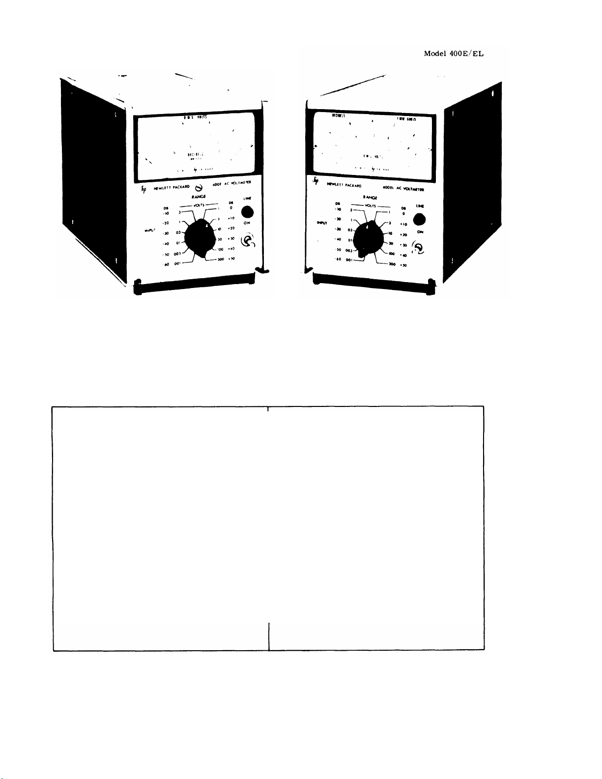
FIGURE l–l.
-hp- MODEL 400E/EL
Voltage Range:
in 12 ranges in 1, 3, 10 sequence. value for a step change.
-72 dbm to +52 dbm in 12 ranges with 10 dbm
between ranges. AC Power:
Frequency Range: 10 Hz to 10 MHz.
Calibration: Responds to absolute average value of
applied signal, calibrated in rms volts.
Input Impedance:
the 1 mv-1 v ranges and 10 megohms shunted by
8 pf on the 3 v-300 v ranges.
Amplifier AC Output: 150 mv rms for full scale
meter indication; output impedance 50 ohms, 10
Hz to 10 MHz (105 mv on the 1 mv range).
AC-DC Converter Output: 1 vdc output for full scale Shipping: 9 lbs. (4 kg).
meter deflection.
Output Resistance: 1000 ohms.
1 mv full scale to 300 v full scale
10 megohms shunted by 21 pf on
MODELS 400E AND 400EL AC VOLTMETERS
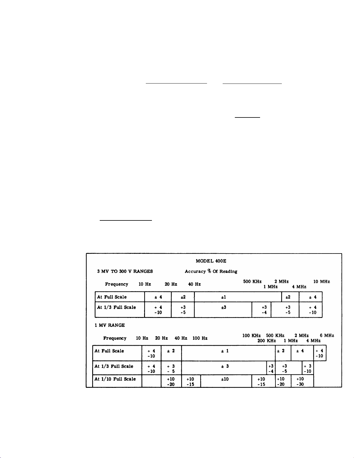
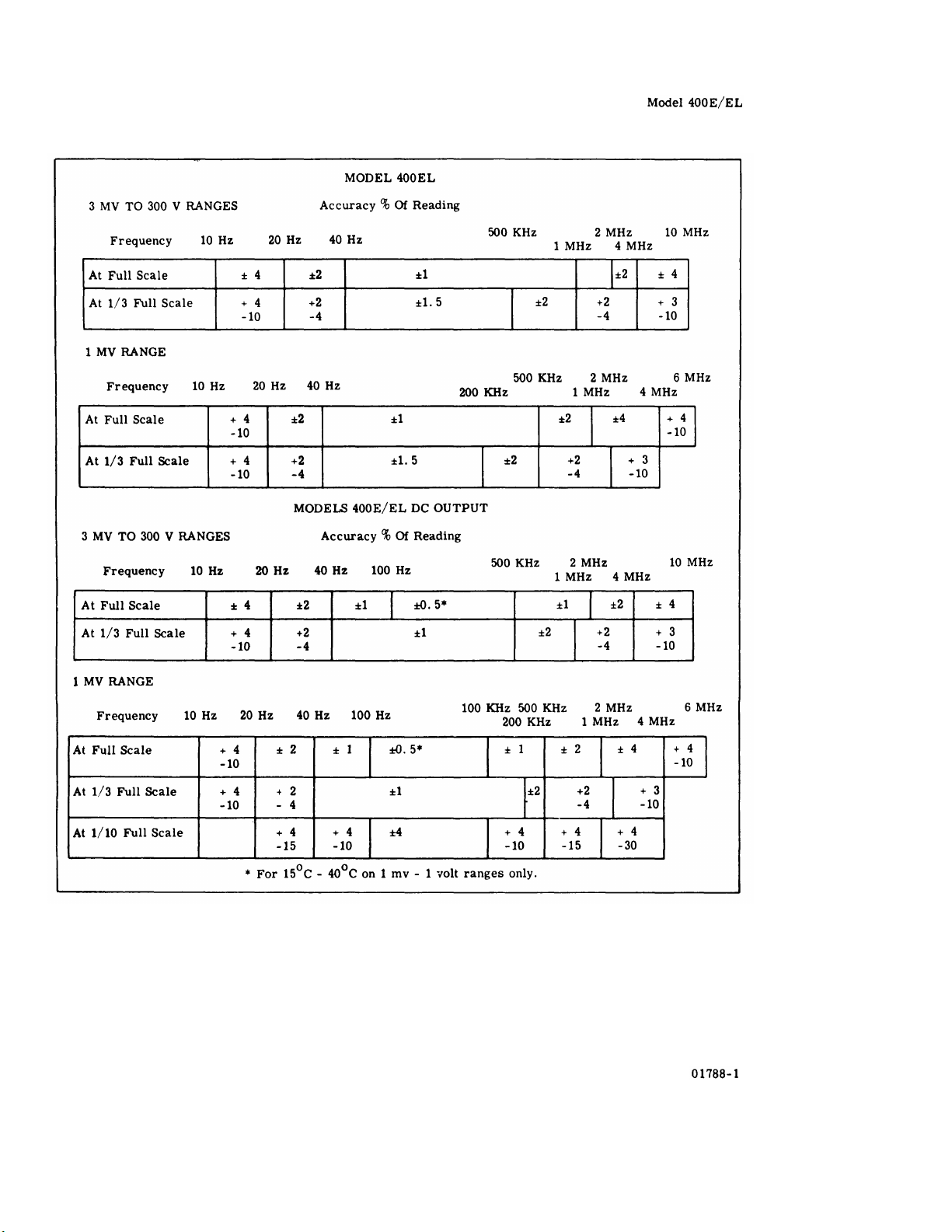
Table 1-1. Specifications
-hp- MODEL 400E/EL (Cont’d)
Response Time: 1 second to within 1% of final
approximately 5 watts.
Temperature Range: 0 to +55°C (except where noted
on accuracy charts).
External Battery Operation: Terminals are provided
on rear panel; positive and negative voltages between 35 v and 55 v are required; current drain
from each voltage is approximately 54 ma.
Weight:
Net: 6 lbs. (2, 7 kg).
Dimensions:
(165, 1 x 130,2 x 279,4 mm).
115 or 230 volts +10%, 50 to 1000 cps,
6-1/2” high, 5-1/8” wide, 11” deep
EL6625—1538—TM—CI—I
1-0
01788-1
Page 11

SECTION I
GENERAL INFORMATION
TM 11-6625-1538-15
1-A.1. SCOPE
This manual includes installation and operation
instruction and covers operator‘s, organizational,
direct support (DS), general support (GS), and
depot maintenance of the Hewlett-Packard AC
Voltmeter AN/USM-265 (Model 400EL02), ME-459
(Model 400EL), and ME-465 (Model 400E). The
repair parts and special tools list are located in
TM 11-6625-1538-24P.
1-A.2. CONSOLIDATED INDEX OF ARMY
PUBLICATIONS AND BLANK FORMS
Refer to the 1 test issue of DA Pam 310-1 to deter-
mine whether there are new editions, changed or
additional publications pertaining to the equipment.
MAINTENANCE FORMS, RECORDS,
1-A.3.
AND REPORTS
Reports of Maintenance and Unsatisfactory
a.
Equipment. Department of the Army forms
and procedures used for equipment maintenance will be those prescribed by TM
38-750, The Army Maintenance Management System.
Report of Packaging and Handling Defi-
b.
ciencies,
(Report of Discrepancy (ROD)) as prescribed in AR 735-11-2/DLAR 4140.55/
NAVMATINST 4355.73A/AFR 400-54/
MCO 430.3F.
c.
Discrepancy in Shipment Report (DISREP)
(SF 361). Fill out and forward Discrepancy
in Shipment Report (DISREP) (SF 361) as
prescribed in AR 55-38/NAVSUPINST
4610.33C/AFR 75-18/MCO P4610.19D/
DLAR 4500.15.
1-A.4.
REPORTING ERRORS AND RECOMMENDING IMPROVEMENTS
You can help improve this manual. If you find any
mistakes or if you know of a way to improve the
Fill out and forward SF 364
procedures, please let us know. Mail your letter or
DA Form 2028 (Recommended Changes to Publications and Blank Forms) direct to: Commander,
US Army Communications-Electronics Command
and Fort Monmouth, ATTN: DRSEL-ME-MP,
Fort Monmouth, New Jersey 07703.
In either case, a reply will be furnished direct to
you.
1-A.5. REPORTING EQUIPMENT IMPROVEMENT
RECOMMENDATIONS (EIR)
If your AC Voltmeter AN/USM-265 needs improvement, let us know. Send us an EIR. You, the user,
are the only one who can tell us what you don’t like
about your equipment. Let us know why you don‘t
like the design.
Deficiency Report). Mail it to Commander, US
Army Communications-Electronics Command and
Fort Monmouth, ATTN: DRSEL-ME-MP, Fort
Monmouth, New Jersey 07703. We’ll send you a
reply.
1-A.6. ADMINISTRATIVE STORAGE
Administrative Storage of Equipment issued to and
used by Army activities will have preventive maintenance performed in accordance with the PMCS
charts before storing. When removing the equipment from administrative storage the PMCS should
be performed to assure operational readiness. Disassembly and repacking of equipment for shipment
or limited storage are covered in paragraphs 2-18
through 2-21, and TM 740-90-1 Administrative
Storage of Equipment.
1-A.7. DESTRUCTION OF ARMY ELECTRONICS
MATERIEL
Destruction of Army electronics materiel to prevent
enemy use shall be in accordance with TM
750-244-2.
Put it on an SF 368 (Quality
Change 2
1-0.1/(1-0.2 blank)
Page 12

Page 13
TM 11-6625-1538-15
Model 400E/EL
In this manual, the international standard unit of frequency,
the Hertz, will be used rather than cycles per second.
1 Hertz (Hz) = 1 cycle per second
1-1. DESCRIPTION.
1-2. The -hp- Models 400E and 400EL are versatile
ac voltmeters and db meters. Both models can be
used as ac to dc converters or wideband amplifiers.
The Model 400E is primarily intended for voltage
measurements, whereas the Model 400EL is primarily
a db meter. However, both meters indicate both volts
and db. The 400E has a linear ac scale with a logarithmic db scale underneath, and the 400EL has a
linear db scale with a logarithmic ac scale underneath.
Since the difference in scales is the only difference
between the two instruments, this manual will use the
term 400E/EL in reference to both instruments.
1-3. Figure 1-1 shows both the Model 400E and the
Model 400EL. Table 1-1 is a list of specifications.
Paragraphs 1-1 to 1-11 and Table 1-1 (Cont’d)
NOTE
1-7. OPTION 02.
1-8. Option 02 adds a relative reference adjustment
to the 400E/EL. The REL. REF. control allows a continuous reduction in sensitivity by a maximum of 3
db in order to make relative voltage or db measurements.
1-9. INSTRUMENT AND MANUAL
IDENTIFICATION.
1-10. Hewlett-Packard instruments are identified by
a two-section, eight-digit serial number (000-00000).
Section I
1-4. OPTIONS AVAILABLE.
1-5. OPTION 01 (400E Only).
1-6. Option 01 places the db scale uppermost for
greater resolution when making db measurements.
Table 1-1. Specifications (Cent’d)
1-11. If the first three digits of the two-section, eight-
digit serial number are prefixed with an E or G, your
instrument was produced in Europe. An E000-00000
serial number indicates that the instrument was manufactured in England; a G000-00000 serial number indicates that the instrument was manufactured in Germany.
01788-1
1-1
Page 14
TM 11-6625-1538-15
Section 1
Table 1-1 (Cont’d)
Table 1-1. Specifications (Cont‘d)
1-2
Page 15

Model 400E/EL
TM 11-6625-1538-15
Section II
Paragraphs 2-1 to 2-21
SECTION II
INSTALLATION
2-1. INTRODUCTION.
2-2. This section contains information and instructions necessary for the installation and shipping of the
Model 400E and 400EL voltmeters. Included are initial inspection procedures, power and grounding requirements, installation information, and instructions
for repackaging for shipment.
2-3. INITIAL INSPECTION.
2-4. This instrument was carefully inspected both
mechanically and electrically before shipment. It
should be physically free of mars or scratches and in
perfect electrical order upon receipt. To confirm
this, the instrument should be inspected for physical
damage in transit. Also check for supplied accessories,
and test the electrical performance of the instrument
using the procedure outlined in Paragraph 5-7.
Report any damage or deficiencies in
accordance with paragraph
1-A. 3.
2-5. POWER REQUIREMENTS.
2-6. The Model 400E/EL can be operated from any
source of 115 or 230 volts at 50 to 1000 cycles or from
two 35 to 55 volt batteries connected to the rear panel
BATTERY terminals.
the rear panel selects the desired line voltage. Power
dissipation is 5 watts maximum.
The 115/230 v slide switch on
2-7. GROUNDING REQUIREMENTS.
2-8. To protect operating personnel, the National
Electrical Manufacturers’ Association (NEMA) recom-
mends that the instrument panel and cabinet be
grounded. All Hewlett- Packard instruments are
equipped with a three-conductor power cable which,
when plugged into an appropriate receptacle, grounds
the instrument.
three-prong connector is the ground wire.
2-9. To preserve the protection feature when operating the instrument from a two-contact outlet, use a
three-prong to two-prong adapter and connect the
green pigtail on the adapter to ground.
The offset pin on the power cable
2-10. INSTALLATION.
2-11. The Model 400E/EL is fully transistorized;
therefore, no special cooling is required. However,
the instrument should not be operated where the
ambient temperature exceeds 55°C (131°F) or the
relative humidity exceeds 95%.
2-12. BENCH MOUNTING.
2-13. The Model 400E/EL is shipped with plastic feet
and tilt stand in place, ready for use as a bench instrument.
2-14. RACK MOUNTING.
2-15. The Model 400E/EL may be rack mounted by
using an adapter frame (-hp- Part No. 5060-0797).
01788-1
The adapter
combination
mounted only.
2-16. COMBINATION MOUNTING.
2-17. The Model 400E/EL may be mounted in combi-
nation with other submodular units by using a Combining Case (-hp- Model 1051A or 1052A). The Combining Case is a full-module unit which accepts various
combinations of submodular units. Being a full- module
unit, the combining case can be bench or rack mounted
and is analogous to any full-module instrument.
2-18. REPACKAGING FOR SHIPMENT.
2-l9. The following paragraphs contain a
general guide for repackaging of the
equipment.
original container is to be used;
paragraph 2-21 if it is not.
2-20. If
follows:
a.
b.
2-21, If
as follows:
a.
b.
c.
d.
frame is a rack frame that accepts any
of submodular units. It can be rack
Refer to paragraph 2-20 if the
original container is to be used, proceed as
Place equipment in original container.
Make sure that container is well
sealed with strong tape or metal bands.
original container is not to be used, proceed
Wrap instrument in heavy paper or plastic before placing in an inner container.
Place packing material around all sides of
instrument and protect panel face with cardboard strips.
Place instrument and inner container in a
heavy carton or wooden box and seal with
strong tape or metal bands.
Mark shipping container with “DELICATE
INSTRUMENT,” “FRAGILE” etc.
2-1
Page 16

TM 11-6625-1538-15
Section III
Figure 3-1
Model 400E/EL
1 400E Scale: Indicates magnitude of applied sig-
nal in volts and dbm. Option 01 places the dbm
scale uppermost for greater resolution. 0 dbm
= 1 mw in 600
2 400EL Scale: Indicates magnitude of applied sig-
nal in volts and dbm. Dbm scale is linear. and
voltage scales are logarithmic. This arrangement allows better resolution for db reading. O
dbm = 1 mw in 600
3 AC INPUT BNC input jack connects signal to
be measured.
4 REL. REF Adjust (Option 02): Lowers sensi-
tivity of meter by 3 db. Fully clockwise ABSO-
LUTE position retains full meter sensitivity.
This control is used to vary meter indication
with a given input in order to make relative
readings easier.
5 RANGE Selector: Selects full scale reading of
meter. Dbm reading on scale adds algebraically
to DB setting of RANGE selector.
Ω.
Ω.
Figure 3-1.
Location of Controls and Indicators
3-0
6 Line ON Toggle Switch Applies primary power.
7 LINE Indicator Lamp: Indicates application of
primary power.
8 FUSE: 1/8 amp. Protects instrument against
current overload.
9 115 230 Volt Slide Switch: Selects 115 or 230
volts ac for line operation.
10 PRIMARY POWER CONNECTOR: Line voltage
is applied through this connector.
11 AC OUTPUT: Ac amplifier output. Output im-
pedance is 50
12 DC OUTPUT: Ac to dc converter output. Dc
voltage is proportional to percentage of meter
deflection. Output impedance is 1000
13 BATTERY VOLTAGE Terminals: 400E/EL may
be powered by connecting two 35 to 55 volt batteries to these terminals.
Ω.
Ω.
01788-1
Page 17

Model 400E/EL
TM 11-6625-1538-15
Section III
Paragraphs 3-1 to 3-8 and Table 3-l and Figure 3-2
SECTION Ill
OPERATING INSTRUCTIONS
3-1. INTRODUCTION.
3-2. The Model 400E/EL is primarily an ac voltmeter
and db meter, but it can be used as an ac to dc converter or as a wide band amplifier.
3-3. This section explains the controls of the 400E/EL
and outlines the operating procedures for each mode
of operation.
3-4. LOCATION OF CONTROLS AND
INDICATORS.
3-5. Figure 3-1 shows the location of each of the
400E/EL controls and explains the function of each.
3-6. OPERATING INSTRUCTIONS.
3-7. STANDARD 400 E/EL.
3-8. AC VOLTMETER.
NOTE
Since the 400E/EL is average responding and rms calibrated, any
distortion will affect the accuracy
of the measurement. Table 3-1
shows the errors caused by distortion.
Table 3-1. Effect of Distortion on Average Respond-
ing Meter
b. To operate the Model 400E/EL with battery
power, connect two 35 to 55 volt batteries as
shown in Figure 3-2. Since the front panel
LINE switch has no effect during battery
operation, the switch in Figure 3-2 can be
used as a convenient method of disconnecting
the batteries when the instrument is not in use.
Figure 3-2. External Battery Connection
a. Ensure that 115-230 vac slide switch on the
rear panel matches line voltage used, and
connect power to the instrument. Mechanically
zero the instrument using the procedure outlined in Paragraph 5-5.
01788-1
Turn line ON toggle switch to up position.
c.
LINE lamp will glow.
d.
Select approximate range of signal to be measured.
DO NOT APPLY MORE THAN
600 VOLTS TO INPUT. DO NOT
OVERLOAD THE .001 THROUGH
1 VOLT RANGES WITH MORE
THAN 300 VOLTS AT FREQUENCIES BELOW 300 KC OR
WITH MORE THAN 64 VOLTS
AT FREQUENCIES ABOVE 300
KC. IF ANY OF THESE OVER-
LOADS ARE EXCEEDED, THE
INSTRUMENT MAY BE DAMAGED.
e.
Connect signal to be measured to INPUT terminals, and read the rms voltage on the scale.
3-1
Page 18

TM 11-6625-1538-15
Section III
Paragraphs 3-9 to 3-16 and Table 3-2
3-9. DB METER.
a. To make a db or dbm measurement, follow
steps a through e in Paragraph 3-8, and add
the scale reading to the RANGE setting. For
example: If the scale reading is +1.5 and the
RANGE is -30 db, the final measurement is
-28.5 db.
b. The 400E/EL db scale is calibrated in dbm.
0 dbm is equivalent to 1 milliwatt dissipated
by a 600 ohm load. Consequently, any dbm
measurements must be made across a total
impedance of 600
other impedances will be in db, but not dbm.
To convert a db reading to dbm, use the Im-
c.
pedance Correction Graph (Figure 3-3). For
example: To convert a +30 db reading made
across 50
on the bottom of the graph. Follow the impedance line to the heavy black line and read
the meter correction at that point. The correction for 50
rected reading is +40.5 dbm.
3-10. AC TO DC CONVERTER.
a. Follow steps a through e in Paragraph 3-8.
b. Connect the rear panel DC OUTPUT terminals
to a dc measuring device with a high input
impedance, The dc output resistance is 1000
Ω; and if it is loaded, the dc output signal will
be inaccurate.
c. The dc output is a 0 to 1 volt signal propor-
tional to the percentage of 400E/EL meter
deflection.
3-11. WIDE BAND AC AMPLIFIER.
a. Follow turn-on steps a through c in Para-
graph 3-8.
b. Select approximate range of input on RANGE
switch.
c. Connect SIGNAL to be amplified to INPUT
terminals.
Ω to dbm, locate the load impedance
Ω is +10.5 dbm, and the cor-
Measurements across
Ω.
Model 400E/EL
d. Connect a 50
AC OUTPUT connector.
e. The gain of the amplifier depends on the
RANGE selection. On the 0.1 volt range and
below, the 400E/EL amplifies the input; and
on the 0.3 volt range and above, it attenuates
the input.
maximum output is 105 mv.
ranges, the maximum output is 150 mv.
Table 3-2 shows the ac amplifier gain for
each range setting.
Table 3-2. AC Amplifier Gain
3-12. 400E WITH OPTION 01.
3-13. Operation of the 400E with Option 01 is essentially the same as operation of the standard 400E.
The db scale reads from -15 to +2 instead of from -12
to +2, and is placed at the top of the scale for better
resolution.
3-14. 400E/EL WITH OPTION 02.
3-15. Option 02 adds a relative reference adjustment
to the 400 E/EL. This adjustment allows a continuous
reduction in sensitivity by 3 db. Use the REL. REF
adjustment to set the meter at any convenient reference (0 db for example) in order to make relative
readings easier. When the REL. REF adjustment is
in the fully clockwise ABSOLUTE position, it has no
effect on the meter sensitivity.
3-16. In all other respects, operation of an Option 02
instrument is the same as operation of a standard
Model 400E/EL.
Ω amplifier load to rear panel
On the 0.001 volt ranges, the
On all other
3-2
01788-1
Page 19

TM 11-6625-1538-15
Model 400E/EL
Section III
Figure 3-3
01788-1
Figure 3-3.
Impedance Correction Graph
3-3
Page 20

Page 21

TM 11-6625-1538-15
Model 400E/EL
SECTION IV
THEORY OF OPERATION
4-1. GENERAL.
4-2. The 400E/EL is a solid state, average respond-
ing, rms calibrated voltmeter. It also has applications as an ac to dc converter and a wide band amplifier. Figure 4-1 shows a simplified block diagram
of the instrument.
4-3. When relay K1 is closed, the input is not attenuated; and when K2 is closed, the input is attenuated
by 50 db. On the 0.001 through 1 volt ranges, K1 is
closed and K2 is open.
on the 3 through 300 volt range. The entire Input Attenuator assembly is shielded, and the relays are
operated remotely by voltages applied through the
RANGE switch. Variable capacitor A1C2 is adjusted
on the 3 volt range with a 3 volt 100 KHz input in order
to shape the frequency response of the Input Attenuator.
4-4. The signal from the input attenuator is applied
to the impedance converter. The impedance converter
is a unity gain, feedback stabilized amplifier that
matches the high Impedance of the Input Attenuator to
the much lower impedance of the post attenuator.
4-5. The Post Attenuator attenuates the output of the
Impedance Converter by 10 db for each step of the
RANGE switch. On the 3 volt range, the Post Attenuator is switched back to the 30 db position, and
then it attenuates 10 db per step on the higher ranges.
Variable capacitor S2C2 is adjusted on the .003 volt
range with a 3 mv 8 MHz input to adjust the 8 MHz
response of the .003 volt range. With a full scale
input on any range except the .001 volt range, the
output of the Post Attenuator should be 3 mv. On the
.001 volt range, the output should be 1 mv.
K2 is closed and K1 is open
Paragraphs 4-l to 4-ll and Figure 4-1
4-6. The Meter Amplifier is a four-stage, high-gain
amplifier utilizing both ac and dc feedback for gain
stabilization. The Meter Bridge, connected in the ac
feedback path of the meter amplifier, converts the ac
output of the amplifier to a dc voltage proportional
to its average value.
A1C28 and A1R38 adjust the gain of the amplifier so
that the meter will read rms volts. A1R28 is adjusted at 400 Hz, and A1C28 is adjusted at 10 MHz.
4-7. The DC Output is a 0-1 volt level that is proportional to percentage of meter deflection. R2 is adjusted to calibrate the dc output. The AC Amplifier
samples the ac feedback and generates O to 150 mv
ac output that is directly proportional to meter deflec t ion.
4-8. SCHEMATIC DESCRIPTION
(See Figure 6-1).
4-9. IMPEDANCE CONVERTER.
4-10. The impedance converter, located on the main
voltmeter board (A2), matches the high impedance of
the input attenuator to the relatively low impedance
of the Post Attenuator. Breakdown diodes A2CR17
and 18 bias diodes A2CR9 and 10 at +5 and -5 volts
respectively. A2CR9 and 10 limit the input to 10 volts
peak-to-peak, providing overload protection. Fuse
A2F1 protects the instrument against destructive
overloads.
4-11. A field-effect transistor (A2Q5) is used in the
input stage of the impedance converter because of its
characteristically high input impedance and good frequency response. The output is taken from the emitter
This dc voltage drives the meter.
Section IV
01788-1
Figure 4-1. Simplified Block Diagram
4-1
Page 22

TM 11-6625-1538-15
Section IV
Paragraphs 4-12 to 4-24 and Figure 4-2
circuit of A2Q7 and applied to the post attenuator and
then applied to the meter amplifier. The solid black
lines on the schematic show the signal path, and the
broken lines show the feedback paths. A2R17 adjusts
the dc bias of the impedance converter.
4-12. METER AMPLIFIER.
4-13. The meter amplifier amplifies its input signal
by a fixed gain on all ranges except the .001 volt
range. The amplifier itself is a four-stage, dc coupled
amplifier with a cascode-coupled final stage (A2Q12
and 13). Dc feedback is coupled from the emitter of
A2Q12 back to the base of A2Q9. Breakdown diodes
A2CR12, 13 and 14 establish fixed dc bias levels in
the amplifier.
4-14. The output from the collector of A2Q13 is coupled
through the Meter Bridge and fed back to the emitter
of A2Q9. A2C28 in the feedback circuit adjusts the
amount of feedback at the high end of the frequency
range, and A2R38 adjusts the feedback at the low end.
This calibrates the amplifier gain at both ends of the
frequency range.
feedback circuit on the 0.001 volt range, boosting the
gain on that range.
of the amplifier.
4-15. METER BRIDGE.
4-16. Figure 4-2 shows a partial schematic of the
Meter Bridge.
amplifier output and supplies the dc current to drive
the meter. In order to use part of the meter bridge
output as the rear terminal dc output, the meter has
to be referenced to ground. Transistor A2Q14 ref-
erences the meter to ground.
4-17. During the positive half cycle, A2CR15 conducts.
Part of the current (solid line) goes through A2C34
into the feedback path, and part of the current goes
through A2R53 and the meter to ground. The current
through A2R53 turns on A2Q14, and A2Q14 draws
current from the positive supply. The current from
A2Q14 goes through A2C36 into the feedback path.
The current through A2Q14 and A2C36 is equal to the
current drawn through the meter, so the current out
of the bridge is equal to the current into the bridge.
4-18. During the negative half cycle, A2CR16 conducts
and draws current from the feedback path (dotted line).
Part of the current goes through A2C36 and A2CR16
into the amplifier, and part goes through A2R53 and
the meter to ground. The current through A2R53
turns on A2Q14, and the current from A2Q14 goes
through A2R54 and A2CR16 to the amplifier, Again
the current through the meter equals
A2R44 and 45 are switched into the
A2R31 adjusts the dc bias level
The meter bridge rectifies the ac
the current
Model 400E/EL
Figure 4-2.
through A2R54, and the current into the bridge equals
the current out.
4-19. Transistor A2Q14 replaces current drawn by
the meter, so the meter bridge is kept floating while
the meter is referenced to ground. The dc output,
taken across A2R65 and R2, is also referenced to
ground.
4-20. AC OUTPUT CIRCUIT.
4-21. The ac output circuit isolates the meter bridge
and amplifier from the ac output load. It consists of
two emitter followers (A2Q15 and Q16) connected in
cascade. A2R59 in the base circuit of A2Q15 zeroes the
output dc level at the ac output.
4-22. POWER SUPPLY.
4-23. The power supply produces regulated +26 volts
and -26 volts.
a reference voltage of 6.98 volts. Part of the power
supply output is applied to the base of A2Q2, and A2Q2
senses the difference between the supply output and
the reference.
emitter to base voltage of A2Q2 will change; and the
output of A2Q2 will change the current through A2Q1,
the regulator.
4-24. The negative regulator, A2Q3 and A2Q4, uses
the +26 volt output as a reference. Consequently, the
negative supply is dependent upon the positive supply.
Breakdown diode A2CR7 establishes
If the output voltage changes, the
Meter Bridge
4-2
01788-1
Page 23

Page 24

TM 11-6625-1538-15
Section V Model 400E/EL
Table 5-1
Table 5-1. Required Test Equipment
5-0
01788-1
Page 25

SECTION V
MAINTENANCE
TM 11-6625-1538-15
5-1. INTRODUCTION.
5-2. This section contains information necessary to
maintain the Model 400 E/EL. The following paragraphs describe the Preventive Maintenance, the
Performance Checks, the Calibration Procedures,
and the Troubleshooting Procedures.
5-3.
REQUIRED EQUIPMENT
5-4. Table 5-1 is a list of the equipment required to
properly maintain the Model 400E/EL. If the model
recommended in Table 5-1 is not available, a substitute may be used as long as it meets the required
specifications
5-4.1. PREVENTIVE MAINTENANCE
NOTE
Refer to TM 750-244-2 for proper
procedures for destruction of this
equipment to prevent enemy use.
a. Operator/crew preventive maintenance is
the systematic care, servicing and inspection
of equipment to prevent the occurrence of
trouble, to reduce downtime, and to maintain equipment in serviceable condition, To
be sure that your voltmeter is always ready
for your mission, you must do scheduled
preventive maintenance checks and services
(PMCS).
(1) BEFORE OPERATION, perform your B
PMCS to be sure that your equipment is
ready to go.
(2) When an item of equipment is reinstalled
after removal, for any reason, perform
the necessary B PMCS (para 5-4.2) to be
sure the item meets the readiness report ing criteria.
(3) Use the ITEM NO. column in the PMCS
table to get the number to be used in the
TM ITEM NO. column on DA Form 2404
(Equipment Inspection and Maintenance
Worksheet) when you fill out the form.
b. There are no organizational PMCS to be
performed.
c. Routine checks like CLEANING, DUSTING,
WASHING, CHECKING FOR FRAYED
CABLES, STOWING ITEMS NOT IN USE,
COVERING UNUSED RECEPTACLES,
CHECKING FOR LOOSE NUTS AND
BOLTS, AND CHECKING FOR COMPLETENESS, are not listed as PMCS checks.
They are things that you should do any time
you see they must be done. If you find a
routine check like one of those listed in your
PMCS, it is because other operators reported
problems with this item.
NOTE
When you are doing any PMCS or
routine checks, keep in mind the
warnings and cautions.
WARNINGS
Adequate ventilation should be
provided while using TRICHLOROTRIFLUOROETHANE. Prolonged breathing of vapor should
be avoided. The solvent should
not be used near heat or open
flame, the products of decomposition are toxic and irritating.
Since TRICHLOROTRIFLUOROETHANE dissolves natural oils,
prolonged contact with skin
should be avoided When necessary, use gloves which the solvent
cannot penetrate. If the solvent
is taken internally, consult a
physician immediately.
NOTES
The PROCEDURES column in
your PMCS charts instruct how to
perform the required checks and
services. Carefully follow these
instructions and, if tools are needed
or the chart so instructs, get
organizational maintenance to do
the necessary work.
If your equipment must be in
operation all the time, check those
items that can be checks and serviced without disturbing operation.
Make the complete checks and
services when the equipment can
be shut down.
d. Deficiencies that cannot be corrected must
be reported to higher category maintenance
personnel. Records and reports of preventive maintenance must be made in accordance with procedures given in TM
38-750.
NOTE
The checks in the interval column
are to be performed in the order
listed.
Change 2
5.1
Page 26

TM 11-6625-1538-15
5-4.2. OPERATOR/CREW PREVENTIVE MAINTENANCE
CHECKS AND SERVICES CHART
B — Before
Equipment is not
Ready/Available
Available equipment is
insufficient to support
the combat mission.
Item
No.
1
Interval
B
●
Item to be
Inspected
Mission
Essential
Equipment
Procedures – Check for and have
repaired or adjusted as
necessary
Check for completeness and satis-
factory condition of the equipment. Report missing items.
.
*Do this check before each deployment to a mission location.
be corrected before the mission starts, The check does not need to be done again until redeployment.
MECHANICAL ZERO ADJUST (400E Only).
5-5.
5-6. Before any performance checks or calibration
is begun, complete the mechanical zero adjustment
in the following steps:
Be sure the meter has been off for at least
a.
one minute,
Rotate mechanical adjustment screw CLOCK-
b.
WISE until meter pointer is to the left of zero
and moving upscale toward zero.
c.
Continue to rotate adjustment screw clockwise.
STOP when needle is exactly on zero. If needle overshoots, repeat step b.
When pointer is exactly over zero, rotate
d.
adjustment screw slightly COUNTERCLOCKWISE to relieve tension on suspension. If the
pointer moves to the left, repeat whole procedure, but make counterclockwise rotation
less.
5-7.
PERFORMANCE CHECKS.
5-8. The performance checks are ‘in cabinet’ tests
that compare the 400E/EL with its specifications.
These procedures can be used for both incoming inspection and periodic inspection.
5-9. ACCURACY AND FREQUENCY RESPONSE
TEST.
sponse of the test oscillator to within 0.2% over its
entire band. Construct the 0 to 10 mv Reference Sup
ply shown in Figure 5-1 and allow it at least 24 hours
to stabilize.
5-12. REFERENCE SUPPLY CALIBRATION.
5-13. Using the following procedure to calibrate the
thermal converter and reference supply.
a. Connect the dc standard, the 400E/EL, the
This will permit any existing problems to
NOTE
The test oscillator used must have
very low distortion (< 170). A
thermal converter and an average
responding circuit react differently
to distortion, and any distortion
present would create a calibration
error.
null voltmeter, the reference supply, and a
3 volt thermal converter as shown in Figure
5-1. Set switch S1 to position A connecting the dc standard output to the thermal
converter input. The reference supply and
the thermal converter are sensitive to variations in ambient temperature. Ensure that
the ambient temperature variations are
less than ±2.0°C.
If:
5-10. The accuracy and frequency response test compares the Model 400E/EL with its accuracy specifications over the entire frequency range. For this test,
a stable voltage reference and an extremely flat broad
band signal generator are needed.
5-11. The test setup in Figure 5-1 uses a thermal con-
verter with a null circuit to adjust the frequency re-
5-2
Change 2
NOTE
If a 400E/EL Option 02 instrument
is used, set the REL. REF adjustment to the fully clockwise ABSOL-
UTE position before making accuracy check.
Page 27

TM 11-6625-1538-15
Model 400E/EL
Figure 5-1. Accuracy and Frequency Response Test Setup
b. Set the dc standard output to +3.000 volts dc.
c. Using the null voltmeter, adjust the reference
supply until its output is within ±l.5 micro-
volt of the thermal converter output.
5-14. MODEL 400E/EL ACCURACY TEST.
5-15. Check the 400E/EL accuracy and frequency
response according to the following steps.
CAUTION
SET TEST OSCILLATOR OUTPUT TO MINIMUM BEFORE
CONNECTING. REDUCE OSCILLATOR OUTPUT BEFORE
CHANGING FREQUENCY RANGE
DO NOT ALLOW OSCILLATOR
OUTPUT TO EXCEED RATED
INPUT OF THERMAL CONVERTER.
ANY OVERLOAD MAY DESTROY
THERMAL CONVERTER.
:
a.
Set switch S-1 in figure 5-1 to position B, connecting the test oscillator to the thermal converter input. Connect the digital voltmeter to
the 400E/EL DC OUTPUT terminals.
b.
Set the 400E/EL Range Switch to 3 volts and
set the oscillator frequency to 10 Hz.
c.
Using the oscillator amplitude control as
coarse adjustment and resistor R4 (Figure 5-1)
as fine adjustment, increase the oscillator
amplitude until the thermal converter output
nulls the reference supply. Observe the
400E/EL meter indication and dc output.
d.
Repeat steps b and c for each frequency listed
in Table 5-2. If the 400E/EL is within speci-
fications, the meter indication and the dc out-
put will be within the tolerances listed in
Table 5-2.
e.
Repeat the procedure in Paragraph 5-1l using
a 1 volt thermal converter and a 1 volt output
from the dc standard.
f.
Repeat steps a through d in this paragraph
using the one volt thermal converter. Set the
400E/EL to the 1 volt range.
Change 2
5-2.1
Page 28

TM 11-6625-1538-15
5-16. RANGE TRACKING TEST.
5-17. The range tracking test checks the accuracy of
the 400E/EL with a 1/3 scale input over its entire
frequency range.
5-18. After verifying the full scale calibration with
the accuracy test in Paragraph 5-13, check the range
tracking with the following procedures.
a. Connect the dc standard, 3 volt thermal con-
verter, dc null voltmeter, and reference sup
ply as shown in Figure 5-1.
b. Set the dc standard output to +3.000 volts dc,
and adjust the reference supply output to null
the thermal converter output.
CAUTION
SET TEST OSCILLATOR OUTPUT
TO MINIMUM BEFORE CON–
NECTING. REDUCE OSCILLATOR
OUTPUT BEFORE CHANGING
FREQUENCY RANGE. DO NOT
5-2.2
Change 2
Page 29

Model 400E/EL
FREQUENCY Hz
10
40
100
1000
10 K
100 K
lM
2M
4M
10 M
TM 11-6625-1538-15
Paragraphs 5-19 to 5-20 and Tables 5-2 to 5-3
Table 5-2. Calibration Tolerant es
3 VOLT RANGE 1 VOLT RANGE
METER
READING OUTPUT
MIN
2.88 3.12 0.911 0.987
2.94 3.06
2.97 3.03
2.97 3.03
2.97 3.03 0.940 0.958 10 K 0.99
2.97
2.97 3.03
2.97 3.03 0.940 0.958 2M 0.99 1.01
2.94
2.88 3.12 0.911 0.987 10 M 0.96
MAX
3.03
3.06
DC
MIN
0.930 0.968
0.940
0.940
0.940 0.958 100 K 0.99 1.01
0.940
0.930 0.968
MAX
0.958
0.958
0.958 lM 0.99 1.01 0.990
FREQUENCY Hz
10
40
100
1000
4M 0.98
METER
READING OUTPUT
MIN
0.96 1.04 0.960
0.96
0.99
0.99
MAX
1.02
1.01 0.990
1.01
1.01
1.02 0.980
1.04
MIN
0.960
0.995
0.995
0.995
0.990
0.960
Section V
DC
MAX
1.040
1.020
1.010
1.005
1.005
1.005
1.010
1.010
1.020
1.040
c.
Disconnect the dc standard, and connect the
test oscillator, the digital voltmeter, and the
400E/EL as shown in Figure 5-1.
d.
Set the 400E/EL RANGE switch to 10 volts
and the oscillator to 10 Hz.
e.
Using the oscillator amplitude control as
coarse adjustment and resistor R4 as a fine
adjustment, set the oscillator output so that
the thermal converter output nulls the reference supply output.
f.
Repeat steps band c for each frequency listed
in Table 5-3 (400E) or Table 5-4 (400EL). If
the 400E/EL is within specifications, the meter
indication and the dc output will be within the
tolerances listed in the tables.
FREQUENCY Hz
100
1000
500 K
01788-1
ALLOW OSCILI.ATOR OUTPUT
TO EXCEED RATED INPUT OF
THERMAL CONVERTER. ANY
OVERLOAD MAY DESTROY 400E/EL to the 3 volt range.
THERMAL CONVERTER.
Table 5-3. 1/3 Scale Tracking Tolerances (400E)
10 VOLT RANGE
METER DC
READING OUTPUT
MAx MIN MAX
0.270
3.09
3.09 0.291 0.309
3.09 0.291
3.09
3.09
3.09
3.12 0.270 0.312
0.291
0.291
0.288
0.285
0.312
0.309
0.309 1000
0.309
0.309 500 K
0.309
0.309
10
40
10 K
lM
4M
10 M
MIN
2.70 3.12
2.85
2.91
2.91
2.91 3.09 0.291
2.91
2.88
2.85
2.70
g. Repeat steps a through fin this paragraph using
a 1 volt thermal converter and a +1.000 volt
dc output from the dc standard. Set the
5-19. INPUT IMPEDANCE CHECK.
5-20. INPUT RESISTANCE CHECK.
a.
Connect the 50
to the input of the 400E/EL.
Set the test oscillator and the 400E/EL to the
b.
3 volt range.
Hz, and adjust the output for a full scale indication.
c.
Connect a 100 K
oscillator output and the 400E/EL input as
shown in Figure 5-2.
The 400E/EL indication should not drop more
d.
than one small scale division from full scale.
This verifies an input resistance of 10 M
3 VOLT RANGE
FREQUENCY Hz READING OUTPUT
10
40
100
10 K
lM 0.96 1.03 0.304
4M 0.95 1.03 0.301
10 M 0.90
Ω output of the test oscillator
Set the oscillator output to 40
Ω resistor between the test
METER
MIN MAX
0.90 1.04 0.285 0.328
0.95 1.03 0.301 0.325
0.97 1.03
0.97
0.97 1.03 0.307 0.325
0.97 1.03 0.307
1.03
1.04 0.285 0.328
DC
MIN
0.307 0.325
0.307
MAX
0.325
0.325
0.325
0.325
Ω.
5-3
Page 30

TM 11-6625-1538-15
Section V
Paragraphs 5-21 to 5-31 and Table 5-4 and Figure 5-2
Table 5-4. 1/3 Scale Tracking Tolerances (400 EL)
Model 400E/EL
FREQUENCY Hz
10
40
100
1000
,
10 K
500 K 2.94 3.06 0.294 0.306 500 K 0.98
10 M
lM
4M
10 VOLT RANGE
METER
READING
MIN MAX MIN
2.70
2.96
2.96
2.96
2.96
2.94 3.06 0.294
2.88
2.70
3.12
3.04 0.297 0.303
3.04
3.04 0.297 0.303
3.04
3.06 0.288
3.07 0.270 0.309 10 M 0.90
OUTPUT
0.270
0.297
0.297
DC
MAX MIN
0.312
0.303
0.303 10 K 0.98
0.306
0.306
FREQUENCY Hz READING OUTPUT
10
40
100
1000
lM
4M
3 VOLT RANGE
METER
MAX MIN
0.90 1.04 0.284 0.304
0.98 1.02 0.311
0.98 1.02 0.311
0.98 1.02
1.02 0.311 0.321
1.02 0.311 0.321
0.98
0.96
1.02 0.310 0.322
1.02 0.304 0.322
1.03 0.284 0.325
DC
0.311
MAX
0.321
0.321
0.321
5-21. INPUT CAPACITY CHECK.
a.
Connect a test oscillator, a 100 K
and the 400E/EL as shown in Figure 5-2. Insert the resistor lead directly into the BNC
connector on the 400E/EL, and connect the
ground lead to the outer shield of the 400E/EL
input connector. Do not use an adapter, as
any adapter will add input capacity.
With the 400E/EL on the 3 volt range, adjust
b.
the test oscillator for a full scale reading on
the 400E/EL at 40 Hz.
Increase the test oscillator frequency until
c.
the 400E/EL indication drops to 2.12 volts.
This should occur at a frequency of 180 KHz
or greater, verifying an input capacity of 8
pf or less on the 3 volt range.
d.
Repeat steps a and b with the 400E/EL on the
1 volt range.
Increase the test oscillator frequency until
e.
the 400E/EL indication drops to 0.707 volts.
This should occur at a frequency of 72 KHz
or greater, verifying an input capacity of 21
pf or less on the 1 volt range.
ALIGNMENT AND CALIBRATION
5-22.
PROCEDURE.
5-23. The calibration adjustments are “cover off”
procedures to adjust the 400E/EL to its performance
5-4
Figure 5-2. Input Impedance Check
Ω resistor,
specifications.
adjusted, refer to the Troubleshooting Procedures
(Paragraph 5-34). Figure 5-3 shows the location of
all the internal adjustments.
5-24. COVER REMOVAL.
5-25. To remove the top or bottom covers, remove
the Phillips screw at the rear of the cover, slide the
cover about 1 inch to the rear, and lift if off. To replace the cover, reverse the removal procedure.
5-26. To remove a side cover, remove the four Phillips
screws and lift it off.
5-27. BIAS ADJUST.
5-28. Connect a dc voltmeter (410C) to TP3 and adjust
A2R17 for -6.0 ±0.25 vdc. Connect a dc voltmeter
to TP4 and adjust A2R31 for +10.0 ±0.5 vdc.
5-29. AC OUTPUT ZERO.
5-30. Connect a dc voltmeter (410C) to TP5 and adjust
A2R59 for 0.0 ±0.050 vdc.
5-31. CALIBRATION.
If the instrument cannot be properly
NOTE
If a 400E/EL Otpion 02 is to be
calibrated, set the REL. REF
adjustment to the fully clockwise
ABSOLUTE position before beginning the calibration.
01788-1
Page 31

Model 400E/EL
TM 11-6625-1538-15
Section V
Paragraphs 5-32 to 5-35 and Figure 5-3
Figure 5-3. Location of Internal Adjustments
5-32. LOW AND HIGH FREQUENCY CALIBRATION.
a. Calibrate the reference supply in Figure 5-1
with a 1 volt thermal converter according to
the steps in Paragraph 5-10.
b.
Disconnect the dc standard and connect the
test oscillator, the 400E/EL, and the digital
voltmeter as shown in Figure 5-1. Set the
oscillator frequency to 400 Hz and the 400E/EL
to the 1 volt range. Using the amplitude control as coarse adjustment and R4 as fine adjustment, increase the oscillator output until
the thermal converter output nulls the ref-
erence supply.
Adjust A2R38 for a 400E/EL meter reading
c.
of 1.004.01 volts.
Adjust R2 for a digital voltmeter display of
d.
1.000 ±0.005 vdc.
e.
Lower test oscillator output and set frequency
to 10 MHz. Readjust oscillator amplitude
until thermal converter output nulls reference
Supply.
Adjust A2C28 for digital voltmeter display of
f.
1.000 ±0.04.
5-33. ATTENUATOR ALIGNMENT.
a. Use the setup shown in Figure 5-1 to align the
attenuator. Calibrate the reference supply
according to the procedures in Paragraph 5-10
using a 3 volt thermal converter.
01788-1
SET TEST OSCILLATOR OUTPUT
TO MINIMUM BE FORE CONNECTING. REDUCE OSCILLATOR
OUTPUT BEFORE CHANGING
FREQUENCY RANGE. DO NOT
ALLOW OSCILLATOR OUTPUT
TO EXCEED RATED INPUT OF
THERMAL CONVERTER. ANY
OVERLOAD MAY DESTROY
THERMAL CONVERTER.
b.
Disconnect the dc standard and connect the
test oscillator and 400E/EL as shown in Figure 5-1. Set the oscillator frequent y to 100
KHz and the 400E/EL to the 3 volt range.
Using the amplitude control as coarse adjustment and R4 as fine adjustment, increase the
oscillator output until the thermal converter
output nulls the reference supply.
Adjust A1C1 in the 400E/EL for a meter
c.
reading of 3.00 volts.
5-34.
5-35. When the 400E/EL operates improperly, first
determine if it is adjusted improperly or if a circuit
is malfunctioning by adjusting and calibrating the instrument according to the procedures in Paragraph 5-22.
with the troubleshooting steps.
TROUBLESHOOTING.
If calibration is impossible, proceed
5-5
Page 32

TM 11-6625-1538-15
Section V
Paragraphs 5-36 to 5-47 and Tables 5-5 to 5-9
5-36. Check the instrument for any obvious evidence
of trouble, such as loose or broken wires or broken
connectors. Check the printed circuit boards for
separations
clean.
5-37. First isolate the trouble to a particular circuit
using the block diagram (Figure 4- 1) and the schematic
(Figure 6- 1). Table 5-5 lists some likely troubles
and their probable causes. Then refer to the trouble-
shooting steps for that circuit.
No response to input.
Instrument will not up-
range above 1 volt, but
works on 1 volt range
and below.
Instrument will not
downrange below 3 v,
but works on 3 v range
and above.
TP3 voltage cannot be
properly adjusted.
or cracks and ensure that all pins are
NOTE
The test voltages shown in this
section are nominal. A tolerance
of ±5% is allowable.
Table 5-5. Troubleshooting Guide
SYMPTOM
PROBABLE TROUBLE
Fuse A2F1 open.
Relay K1 stuck closed.
Relay K2 stuck closed.
Impedance Converter
(A2Q5, 6, and 7).
Model 400E/EL
5-42. If the voltage at pin 22 is low, pull the wht/orn/
yel wire from pin 22,
the wire. It should be 3 mv. If the voltage on the
wire is proper, the trouble is in the meter amplifier
If it isn’t correct, the trouble is either in the Post
Attenuator or the Impedance Converter.
5-43. To check the Impedance Converter, measure the
ac voltage at its output (A2 pin 21). The output voltage
should be very close to the input voltage since the Im-
pedance Converter is a unity gain amplifier. With a
1 volt input, the output should be 0.98 volts ±0.02 volts.
5-44. Both the Impedance Converter and the meter
amplifier are internally dc coupled. If the dc voltages
anywhere in the amplifier are incorrect, the amplifier
won’t operate properly.
dc voltages is a good check of the amplifiers.
5-45. Tables 5-7 and 5-8 contain the dc voltages on
all of the transistors in the meter amplifier and the
Impedance Converter.
given transistor is wrong, the trouble is probably in
that transistor or its associated circuit.
Measure these dc voltages with
the in,put shorted. A dc voltmeter
with low input capacitance and
very high input resistance must
be used. The -hp- Model 410C
is recommended.
Table 5-7. Impedance Converter Voltages
and measure the ac signal at
Consequently a check of the
If the measured voltage on a
NOTE
properly adjusted.
5-38. POWER SUPPLY.
5-39. Check with a dc voltmeter (410C) at TP1 and
TP2 for +26 volts and -26 volts respectively. If the
TP voltages are improper, check the voltages listed
in Table 5-6. If the voltage for a given component
is wrong, the trouble is probably in that component
or its associated circuit.
Table 5-6.
COMPONENT
Collector Q1
Collector Q2
Emitter Q2
Base Q3
Collector Q3
Collector Q4
5-40. AMPLIFIERS.
5-41. Set the 400E/EL to the 1 volt range, and connect
a full scale input. With a sensitive ac voltmeter,
monitor the ac amplifier output at the negative side of
A2C34 or A2C36. The output should be 150 mv. If
it is not 150 mv, measure the ac voltage at A2 pin 22.
The voltage at pin 22 should be 3 mv. If these two
voltage readings are correct, the meter amplifier and
meter bridge are operating properly.
- 13).
Power Supply Voltages
VOLTAGE
I
+39 v
+26. 5 v
+6.98 v
-0.6 v
-23.5 v
-39 v
5-6
TRANSISTOR E
Q5
Q6
Q7
Table 5-8. Meter Amplifier Voltages
TRANSISTOR
Q8
Q9
Q1O
Qll +1.25 v
Q12
Q13
Q14* - 0.45 v
5-46. AC OUTPUT CIRCUIT.
5-47. To check the ac output circuit, measure the dc
voltages at the points shown in Table 5-9. If a given
measured voltage is incorrect, the trouble is probably
in that component or its associated circuit.
Table 5-9. AC Voltage Output Circuit
TRANSISTOR
Q15 +0. 68 v
916 0
(S)-6 v
-15 v
- 6.7 v
* Cannot be measured.
E
+22. 25 v
+0.02 v
+ 8.2 v
+9
+0.27 v
* In bridge circuit.
E B
B
(G) *
-14.3v - 7.4v
- 7.4v
B
+23 v +25. 5 v
+0.57 v
+7.5 v +1.8 v
+1.8 v
+8
v
v
0
+ 0.02 v
+1.3 v
+0. 66 v
c
(D) 14. 4V
-21.5v
c
+7.5 v
+8 v
+0.27 v
-6.2 v
+26 v
c
+4. 6 V
+4. 6 V
01788-1
Page 33

TM 11-6625-1538-15
Model 400E/EL
5-48. ADJUSTMENT OF FACTORY SELECTED
COMPONENTS.
5-49. Certain components within the Model 400E/EL are
individually selected in order to compensate for slightly
varying circuit parameters. These components are
denoted by an asterisk (*) on the schematic, and the
typical value is shown.
function of the factory selected components and gives
instruct ions for their select ion.
components do not need to be changed unless another
associated component is changed. Replacement of a
transistor, for example, may require the changing
of a factory selected component.
Table 5-10 describes the
Normally, these
Paragraphs 5-48 to 5-49 and Table 5-10
Table 5-10. Factory Selected Components
COMPONENT FUNCTION AND SELECTION
A2C12*
A2C31*
A2R44*
S2C4*
56 to 110 pf. Adjusts 2 MHz re-
sponse of impedance converter.
With consistently high readings at
2 MHz on 1 volt range, decrease
A2C12.
18 to 22 pf. Adjusts 10 Hz re-
sponse on 3 volt range. With con-
sistently low readings at 10 Hz on
3 volt range, decrease A2C31.
110-182
sponse on the 1 mv range. With
consistently low readings, decrease A2R44.
1.8 to 6.8 pf. Adjusts 10 Hz response on 1 mv and 3 mv range.
With consistently high readings at
10 Hz on 3 mv or 1 mv range, decrease S2C4.
Ω. Adjusts 400 Hz re-
Section V
01788-1
5-7
Page 34

Page 35

TM 11-6625-1538-15
Model 400E/EL
SECTION VI
CIRCUIT DIAGRAMS
6-1. INTRODUCTION.
6-2. This section contains the circuit diagrams necessary for maintenance of the Model 400E/EL. A
Paragraphs 6-1 to 6-2
Section VI
schematic, a component location drawing, and a diagram of the RANGE switch are included. Location
grids are drawn on the more complicated diagrams
making the search for individual components easier.
01788-1
6-1
Page 36

TM 11-6625-1538-15
Section VI
Figure 6-1
Model 400E/EL
6-2
p/o Figure 6-1.
400E/EL Schematic Diagram and Location of Components
01789-1
Page 37

APPENDIX A
REFERENCES
TM 11-6625-1538-15
DA Pam 310-1
TM 11-6626-1538-24P
TM 38-740
TM 740-90-1
TM 750-244-2
Consolidated Index of Army Publications and Blank Forms.
Organizational, Direct Support, and General Support Maintenance Repair Parts
and Special Tools List for Voltmeters, AN/USM-265 (NSN 6625-00-935-
4294), ME-459 (6625-00-229-4457) and ME-465 (6625-00-995-7716).
The Army Maintenance Management System (TAMMS).
Administrative Storage of Equipment.
Procedures for Destruction of Electronics Materiel to Prevent Enemy Use.
Change 2
A-1/(A-2 blank)
Page 38

Page 39

APPENDIX D
MAINTENANCE ALLOCATION
Section I. INTRODUCTION
TM 11-6625-1538-15
D-1. General
This appendix provides a summary of the
maintenance operations for AC Voltmeter
AN/USM-265, ME-459, and ME-465. It au-
thorizes categories of maintenance for specific
maintenance functions on repairable items and
components and the tools and equipment required to perform each function. This appendix
may be used as an aid in planning maintenance
operations.
D-2. Maintenance Function
Maintenance functions will be limited to and
defined as follows:
a. Inspect. To determine the serviceability of
an item by comparing its physical, mechanical,
and/or electrical characteristics with established standards through examination.
b. Test. To verify serviceability and to detect
incipient failure by measuring the mechanical
or electrical characteristics of an item and
comparing those characteristics with prescribed
standards.
c. Service. Operations required periodically to
keep an item in proper operating condition, i.e.,
to clean (decontaminate), to preserve, to drain,
to paint, or to replenish fuel, lubricants, hydraulic fluids, or compressed air supplies.
d. Adjust. To maintain, within prescribed
limits, by bringing into proper or exact position,
or by setting the operating characteristics to the
specified parameters.
e. Align. To adjust specified variable elements
of an item to bring about optimum or desired
performance.
f. Calibrate. To determine and cause corrections to be made or to be adjusted on instruments or test measuring and diagnostic
equipments used in precision measurement.
Consists of comparisons of two instruments, one
of which is a certified standard of known
accuracy, to detect and adjust any discrepancy
in the accuracy of the instrument being compared.
g. Install.
fixing into
(component
the proper
system.
h. Replace. The act of substituting a service-
able like type part, subassembly, or module
(component or assembly) for an unserviceable
counterpart.
i. Repair. The application of maintenance
services (inspect, test, service, adjust, align,
calibrate, replace) or other maintenance actions
(welding, grinding, riveting, straightening,
facing, remachining, or resurfacing) to restore
serviceability to an item by correcting specific
damage, fault, malfunction, or failure in a part,
subassembly, module (component or assembly),
end item, or system.
.j. Overhaul.
(service/action) necessary to restore an item to a
completely serviceable/operational condition as
prescribed by maintenance standards (i.e.,
DMWR) in appropriate technical publications.
Overhaul is normally the highest degree of
maintenance performed by the Army. Overhaul
does not normally return an item to like new
condition.
k. Rebuild. Consists of those services/actions
necessary for the restoration of unserviceable
equipment to a like new condition in accordance
with original manufacturing standards. Rebuild is the highest degree of materiel maintenance applied to Army equipment. The rebuild
operation includes the act of returning to zero
those age measurements (hours, miles, etc.)
considered in classifying Army equipments/
components.
The act of emplacing, seating, or
position an item, part, module
or assembly) in a manner to allow
functioning of the equipment or
That maintenance effort
D-3. Column Entries
a. Column 1, Group Number. Column 1 lists
group numbers, the purpose of which is to
identify components, assemblies, subas-
semblies, and modules with the next higher
assembly.
Change1 D-1
Page 40

TM 11-6625-1538-15
b. Column 2, Component/Assembly. Column 2
contains the noun names of components, assemblies, subassemblies, and modules for which
maintenance is authorized.
c. Column 3, Maintenance Functions. Column
3 lists the functions to be performed on the item
listed in column 2. When items are listed without
maintenance functions, it is solely for purpose of
having the group numbers in the MAC and
RPSTL coincide.
d. Column 4, Maintenance Category. Column 4
specifies, by the listing of a “work time” figure in
the appropriate subcolumns(s), the lowest level
of maintenance authorized to perform the
function listed in column 3. This figure represents the active time required to perform that
maintenance function at the indicated category
of maintenance. If the number or complexity of
the tasks within the listed maintenance function vary at different maintenance categories,
appropriate “work time” figures will be shown
for each category. The number of task-hours
specified by the “work time” figure represent
the average time required to restore an item
(assembly, subassembly, component, module,
end item or system) to a serviceable condition
under typical field operating conditions. This
time includes preparation time, troubleshooting
time, and quality assurance/quality control time
in addition to the time required to perform the
specific tasks identified for the maintenance
functions authorized in the maintenance allocation chart. Subcolumns of column 4 are as
follows:
C
— Operator/Crew
O
— Organizational
F — Direct Support
H — General Support
D — Depot
e. Column 5, Tools and Equipment. Column 5
specifies by code, those common tool sets (not
individual tools) and special tools, test, and
support equipment required to perform the
designated function.
f. Column 6, Remarks. Not applicable.
D-4. Tool and Test Equipment Require-
ments (See Ill)
a. Tool or Test Equipment Reference Code. The
numbers in this column coincide with the
numbers used in the tools and equipment
column of the MAC. The numbers indicate the
applicable tool or test equipment for the main-
tenance functions.
b. Maintenance Category. The codes in this
column indicate the maintenance category
allocated the tool or test equipment.
c. Nomenclature. This column lists the noun
name and nomenclature of the tools and test
equipment required to perform the maintenance functions.
d. National/NATO Stock Number. This column
lists the National/NATO stock number of the
specific tool or test equipment.
e. Tool Number. Not applicable.
D-5. Remarks (See IV)
a. Reference Code. This code refers to the
appropriate item in section II, column 6.
b. Remarks. This column provides the re-
quired explanatory information necessary to
clarify items appearing in section II.
D-2
(Next printed page is D-3.)
Change 1
Page 41

TM 11-6625-1538-15
(1)
GROUP
NUMBER
00
SECTION II MAINTENANCE ALLOCATION CHART
VOLTMETER AN//USM-265, ME-459, AND ME-495
COMPONENT ASSEMBLY
AC VOLTMETER AN/USM 265, NE-459,
(2)
AND
465
FOR
(3)
MAINTENANCE
FUNCTION
Inspect
Test
Test
Service
Adjust
Repair
Repair
Overhaul
MAINTENANCE CATEGORY
(4)
F
O
C
0.2
0.3
0.4
0.2
0.8
0.5
0.6
2.0
H
(5)
TOOLS
AND
D
EQPT.
8
1 thru 8
1 thru 9
8
1 thru 7
1 thru 8
1 thru 9
1 thru 8
(6)
REMARKS
Change 1
D-3
Page 42

TM 11-6625-1538-15
TOOL OR TEST
EQUIPMENT
REF CODE
1
2
3
4
5
6
7
8
9
MAINTENANCE
CATEGORY
O, H, D
O, H, D
O, H,D
0, H, D
O, H, D
O, H, D
O, H, D
O, H
H, D
SECTION III
TOOL AND TEST EQUIPMENT REQUIREMENTS
FOR
VOLTMETER AN//USM-265, ME-459, ME-465
NOMENCLATURE
OSCILLATOR TS-221/TSM HP-651A
DC VOLTMETER ME-231/FYQ-5, HP-3440A
DC NULL METER HP-419A
THERMAL CONVERTERS HP-HO 2-11049A
THERMAL CONVERTER HP-11050A
DC SUPPLY, ME-202 (*)/U, HP-741B
AC-DC VOLTMETER ME-26/U, HP-410A
TOOLS AND TEST EQUIPMENT AVAILABLE TO THE REPAIRMAN BECAUSE
OF HIS ASSIGNED MISSION
NATIONAL NATO
STOCK NUMBER
625-00-910-0849
625-00-013-2630
625-00-212-6589
931-00-111-6681
931-00-130-5381
625-00-709-0288
625-00-360-2493
TOOLS AND TEST EQUIPMENT MOUNTED IN AN/TSM 55 (V)
TOOL NUMBER
D-4 Change 3
Page 43

TM 11-6625-1538-l5
TECHNICAL MANUAL
No. TM 11-6625-1538-15)
TM 11-6625-1538-15 is published for the use of all concerned.
By Order of the Secretary of the Army:
Official:
KENNETH G. WICKHAM
Major General, United States Army,
The Adjutant General.
Distribution:
Active Army:
HEADQUARTERS
DEPARTMENT OF THE ARMY
WASHINGTON, D. C.
HAROLD K. JOHNSON,
General,
Chief of Staff.
11 May 1967
United States Army,
Page 44

Page 45

Page 46

Page 47

Page 48

PIN: 019315-000
 Loading...