

Page 1
Service Handbook
HP Apollo 9000 Series 400
Models 400dl, 400t, 425t, 400s, 425s, 433s
Order No. A1630-90#9
Manufacturing No. A1630-90614
HEWLETT
E!!i!i
PACKARD
Page 2
NOTICE
~ ktfOmSSHOfIcontelned
inthledocument is subjacf10changewlfhoufnotloa,
tiEWLtEfT-PACKARDMAKESNOWARRANWOFANYI(JNDWITHREGARDTOTHISMANUAL,INCLULS
lNt3.SUl NOTUMrfEDTO,THEIMPLIEDWARRANTIESCWMERCHANTASILIWAND F~ESS FORA
~LAR PURPOSE.Hawtatf-Packerdehallnotbe Ilebtefor erromcontainedhereinordkacl, Indlract.
=l~tinm oramaequenflaldamagesIncorrnactkmrwffhIhefumlshlngperfomsanca
orw ofthis
WARRANTY
Acopyof thespeclftowarrantyterm applicabletoyourHewfelt-packardproductand replacementpans
_* be obtetnedfrom
yourlocalSeteeand ServtceCmcs.
Cw@9hf@ Hawietf+eckard Companywst
mk dmumentconfelnsInformationvmkh Isprotectedby
co#rlghl. AllrigMsarerasarvad. Fiepmductlon,adep
tetlors,WIWISISWI withoufpriorwrirfenperrnlsalonlap+ohl ad, exceptasallowedunderthe-M law
ReettWedRQhtLqsmd
Use.duptlcatlmordlschxrre b theU.S.Government0s
)lte
Cefensalasubacttoraesrtcflonsesearforth
mpmgreph (b)(3)(n)01theRlg In TeohntcalDafaand
#8!!’c&elrrFAR52J2T-7o13.
C%@@@ AThT. Ino.19S0,19S4
@@9f@ Thefwems oftheUntwsnYof OaIifornra1979. wso, w3
Thiseo4twamenddocumantetlonla bawd Inpan cmtheFourthSerkelsySofIwareDlstrtbut!onunderIlcanceIrom
theRegentsoftheUnhwelfyof Callfomla
ii
Page 3
New editions of this manual incorporate all material updated since the previous
edition. Update packages ma be issuedbetween editions and contain replace-
ment and additional pages to~merged intothemanualby the user. Note that
pages
which are rearranged due to changes on a previous page are not consid-
ered revised.
The manual printing date and part number indicate its current edition. The
printing date changes when a new edition is printed. (Minor corrections and
updates which are incorporated at reprint do not cause the date to change.) The
manual part number changes when extensivetechnical changes are incorporated.
July 1990...Edition1
October 1991...Edition2
Page 4
Emissions Regulations
Federal Communications Commission (FCC)
T#oFederal Communications Commission of the U.S. government regulates the
9
uencyenergy emanated b computing devicesthrough published regu-
{
lations. hese regulations specifyt e limitsof radio frequency emission to
pro-
tect radio and televisionreception. All HP Apollo nodes and peripherals have
been tested and complywith these limits. The FCC regulations also r uire that
7
com uting devicesused in the U.S. displaythe agency’slabel and that t e re-
e(!
Iat documentation include the followingstatement.
WARNING:
This equipment generates, uses,and may emit radio frequency energy and, if not installedand used in accordance
with these instructions,maycause interference to radio communications. It has been tested and found to complywith the
limits for a ClassA computing devi~ pursuant to Subpart J of
Part 15of FCC Rules, which are designed to provide reason-
able protection against such interference when operated in a
commercialenvironment. Operation of this equipment in a
residential area islikelyto cause interference, in which case
the user at his ownexpensewillbe required to take whatever
measures may be required to correct the interference.
Complianceto these regulations requires the usc of shielded cables.
Canadian Department of Communications (DOC)
This digital apparatus does not exceed the ClassA limits for radio noise emissionsfrom di~tal apparatus asset out in the Radio Interference Requirements
of the Canad]an Department of Communications.
Compliance to these regulations requires the usc of shielded cables.
Verband Deutscher Elektrotechniker (WE)
Herstellerbescheinigung
Hierrnit wird bescheinigt,drd3der diescs Ger5t in &reinstimmung mit den
Bestimmungender Pastverfiigung1046/84funkentstiit ist.
Der Deutschen Bundespostwur~edas Inverkehrbringen dicser Geriites an e-
zigt
und die Berechtigung zur Uberpriifimgder Serie auf Einhaltung der
%es-
timmungen einger~umt.
Die Elnhaltung dieser Grenzwcrte schreibt den Gebrauch abgeschirmter Kabel
vor.
J3ewIett-Packad Gmb~
r
iv
Page 5
VCCI Class 1 ITE Equipment
Emissions Regulations Compliance
Any third-party I/O deviee installed in HP Apollo system(s)must be in aeeordanee with the requirements set forth in the preceding EmissionsRe@ations
statements. In the event
that a third-party noncompliant 1/0 deviceISinstalled,
the customer assumes all responsibilityand liabilityarising therefrom.
Compliance to these regulations requires the use of shielded cables
Page 6
Acoustics
Regulation On Noise Declaration for Machines -3. GSGV
Lpa c 70dB
J-pa c70dB
operator position am Arbeitsplatz
normal o nation
?%
normaler Betrieb
per 1S0 nach DIN 45635T 19
Electrostatic Discharge (ESD) Precautions
Electrostatic charges can damage the integrated circuitson printed circuit
boards.To prevent such damage from owtn-ring,observe the followingprecautionswhen unpacking and installingthe board.
●
●
●
●
●
vi
Stand on a static-free mat.
Wear a static strap to ensure that any accumulated electrostatic charge will
& discharged from your body to ground.
Connect allequipment.together, includingthe static-free mat, static straps,
routing nodes, and peripheral units,
Keep uninstalled printed circuit boards in their protective antistatic bags.
Handle printed circuit boards bytheir edges,once you have removed them
from their protective antistatic bags.
Page 7
Contents
Chapter 1
Product Information
Part 1
Part
2
Model 400t, 425t, and 400dl
Model 400t and 425t Overview . . . . . . . . . . . . . . 1-1
Mode1400d10verview ..,,..... . . . . . . . . . . . . 1-2
Physical Configurations . . . . . . . . . . . . . . . . . . . . . 1-3
System Unit
. . . . . . . . . . . . . . . . . . . . ., ..,,
1-4
Monitors . . . . . . . . . . . . . . . . . . . . . . . . . . . . . 1-4
Keyboards . . . . . . . . . . . . . . . . . . . . . . . . . . . 1-4
Winchester Disk Drive Specifications . . . . . . 1-5
Model 400s, 425s, and 433s
Overview . . . . . . . . . . . . . . . . . . . . . . . . . . . . . . . . 1–6
Accessory Cards/Boards . . . . . . . . . . . . . . . . . . . . 1-9
Supported DIO Accessory Boards . . . . . . . . 1-9
Supported AT-Compatible Accessory Boards 1-10
Physical Configurations . . . . . . . . . . . . . . . . . . . . . 1-10
System Units . . . . . . . . . . . . . . . . . . . . . . . . . 1-10
Monitors and Graphics Controllers . . . . . . . 1-11
Keyboards . . . . . . . . . . . . . . . . . . . . . . . . . . . 1-12
Internal Mass Storage . . . . . . . . . . . . . . . . . . 1-12
Contents vii
Page 8
Chapter 2
Environmental/
Installation/PM
Model 400t, 425t, and 400dl System Units . . . . 2-1
Environmental Specifications . . . . . . . . . . . . 2-1
Regulatory Requirements . . . . . . . . . . . . . . . . 2-1
Installation . . . . . . . . . . . . . . . . . . . . . . . . . . . 2-2
Preventive Maintenance . . . . . . . . . . . . . . . . 2-2
Model 400s, 425s, and 433s System Units . . . . . 2-3
Environmental Specifications . . . . . . . . . . . . 2-3
Regulatory Requirements . . . . . . . . . . . . . . . . 2-3
Installation . . . . . . . . . . . . . . . . . . . . . . . . . . . 2-4
Preventive Maintenance . . . . . . . . . . . . . . . . 2-4
Chapter 3
Configuration
Workstation and System Unit Configurations . . . 3-1
FRU Configurations . . . . . . . . . . . . . . . . . . . . . . . . 3-1
CPU Board Configurations . . . . . . . . . . . . . . 3-1
HP A14 16A VRX Color Graphics Controller 3-5
HP A 1096A VRX Monochrome
Graphics Controller . . . . . . . . . . . . . . . . . . . . 3-6
802.5 Network Controller-AT . . . . . . . . . . . 3-7
Apollo Token Ring Network Controller-AT 3-9
PC Coprocessor Board . . . . . . . . . . . . . . . . . 3-11
Rodime 200 MB Disk Drive , . . . . . . . . . . . . 3-12
Quantum 200 MB and 400 MB Disk Drive 3-13
Hewlett-Packard 400 MB Disk Drive . . . . . 3-14
Micropolis 660 MB and 1.3 GB Disk Drives 3-16
Hewlett–Packard 1.3 GB Disk Drive . . . . . . 3-18
HP A1449A 0.25-in. QIC 60-MB
Tape Drive . . . . . . . . . . . . . . . . . . . . . . . . . . . 3-20
HP A1448A CD-ROM Drive . . . . . . . . . . . . 3-21
HP A1447A DAT Tape Drive . . . . . . . . . . . 3-22
Series 400 Systems EEPROM . . . . . . . . . . . . . . . . 3-23
Transferring an EEPROM to a Replacement
CPU Board . . . . . . . . . . . . . . . . . . . . . . . . . . 3-23
Replacing a Defective EEPROM , . . . . , . . . . 3-26
...
VIII
Contents
Page 9
Configuring the EEPROM on HP-UX
●
Compatible Mode Systems . . . . . . . . . . . . . . . . . .
Boot Mode Selection . . . . . . . . . . . . . . . . . . .
Auto System Select Mode for HP-UX
Compatible
Mode Systems . . . . . . . . . . . . . . . . . . . . . . . .
●
Internal 1/0 Configuration Mode for
HP-UX Compatible Mode Systems . . . . . . .
Configuring the EEPROM on Domain
Compatible Mode Systems . . . . . . . . . . . . . . . . . .
Selecting Domain Compatible
Mode . . . . . .
●
Selecting the Primary Network . . . . . . . . . . .
Selecting the System Clock Speed . . . . . . . .
Connecting Terminals to Domain Compatible
Mode Systems . . . . . . . . . . . . . . . . . . . . . . . . . . . .
Using a Field Terminal . . . . . . . . . . . . . . . . .
Using a Workstation as a Terminal
. . . . . . .
3-28
3-28
3-29
3-30
3-32
3-32
3-35
3-36
3-38
3-38
3-38
Chapter 4
Troubleshooting
Troubleshooting in Domain Compatible Mode .,
Troubleshooting in HP-UX Compatible Mode . .
Troubleshooting Flowcharts for Domain Mode . .
HP-UX Troubleshooting Flow Charts . . . . . . . . .
Checkout Procedures for Model 400t, 425t, and
400dl Systems . . . . . . . . . . . . . . . . . . . . . . . . . . . .
Power Supply Verification for the Model
400t, 425t, and 400dl Systems . . . . . . . . . . .
Winchester Disk Power Checkout for the
Model 400t and 425t System Units . . . . . . .
●
Calendar Battery Checkout for Model 400t,
425t, and 400dl Systems That Use Domain
Compatible Mode . . . . . . . . . . . . . . . . . . . . .
Checkout Procedures for the Model 400s,
425s, and433s System Units.... . . . . . . . . . . . .
●
Power Supply Verification for 400s, 425s,
and 433s System Units
. . . . . . . . . . . . . . . . .
Main Power Distribution Cable Connectors .
Calendar Battery Checkout for Model 400s,
●
425s, and 433s Systems That Use Domain
Compatible Mode . . . . . . . . . . . . . . . . . . . . .
4-1
4-1
4-2
4-12
4-15
4-16
4-21
4-22
4-23
4-23
4-26
4-29
Contents
ix
Page 10
Memory Module Failures . . . . . . . . . . . . . . . . . . . 4-30
HP-UX Compatible Mode Error Messages . . . . . 4-33
“UNEXPECTED” Error Messages . . . . . . . . 4-33
Chapter 5
Diagnostics
Mnemonic Debugger Self Test Diagnostics
., .,. 5-1
Running the Standard Self Test Diagnostics 5-1
Running the Extended Self Test Diagnostics 5-1
Running the Continuous Self Test
Diagnostics . . . . . . . . . . . . . . . . . . . . . . . . . . . 5-2
LED Status and Error Messages . . . . . . . . . . . . . 5-2
HP-UX Boot ROM Test Diagnostics . . . . . . . . . . 5-4
Boot ROM Self-Test LED Displays . . . . . . . 5-4
General Failure Code Descriptions . . . . . . . . 5-4
State and Failure Codes . . . . . . . . . . . . . . . . 5-6
Boot ROM Messages . . . . . . . . . . . . . . . . . . . 5-9
Using the Boot ROM Test Mode for
HP-UX Systems . . . . . . . . . . . . . . . . . . . . . . 5-13
Using the HP–UX ce.utilities . . . . . . . . . . . . 5-14
Chapter 6 Peripherals
Chapter 7
Field Replaceable Units
Model 400t, 425t, and 400dl System Units . . . . 7-1
Model 400s, 425s, and 433s System Units . . . . . 7-4
Chapter 8
Diagrams
Model 400t, 425t, and 400dl System Units ., . . 8-1
Model 400s, 425s, and 433s System Units . . . . . 8-4
x
Contents
Page 11
Chapter 9
Reference
Installation Manuals . . . . . . . . . . . . . . . . . . . . . . . 9-1
Service Manuals
,. ..,!.. . . . . . . . . . . . . . . . . .0
9-1
Reference Manuals . . . . . . . . . . . . . . . . . . . . . . . . 9-2
Chapter 10
Service Notes
Page 12
Figures
1-1
1-2
3-1
3-2
3-3
3-4
3-5
3-6
3-7
3-8
3-9
3-1o
3-11
3-12
3-13
3-14
3-15
3-16
3-17
3-18
HP Apollo Model 400t, 425t, or 400dl
Workstation . . . . . . . . . . . . . . . . . . . . . 1-3
HP Apollo Model 400s, 425s, or 433s
System . . . . . . . . . . . . . . . . . . . . . . . . . 1-8
Jumper Configurations for CPU Boards
Without Integrated Graphics . . . . . . . 3-2
Jumper Configurations for the CPU
Board with Integrated Graphics . . . . . 3-3
HP A1416A Color Graphics Controller
Switch Configuration . . . . . . . . . . . . . . 3-5
VRX Monochrome Graphics Controller
Jumpers . . . . . . . . . . . . . . . . . . . . . . . .
3-6
Standard 802.5 Network Controller-AT
Jumper Configuration . . . . . . . . . . . . . 3-7
Alternate 802.5 Network
Controller-AT Jumper Configuration . 3-8
Apollo Token Ring Network
Controller-AT Jumper Settings . . . . . 3-9
Alternate Apollo Token Ring Network
Controller-AT Jumper Settings . . . . .
3-1o
PC Coprocessor Standard Jumper
Configurations . . . . . . . . . . . . . . . . . . .
3-11
PC Coprocessor Alternate Jumper
Configurations . . . . . . . . . . . . . . . . . . .
3-11
200 MB Rodime Winchester Disk Drive 3-12
200 MB and 400 MB Quantum
DiskDriv e. . . . . . . . . . . . . . . . . . . . .
3-13
200 MB and 400 MB Quantum
Disk Drive . . . . . . . . . . . . . . . . . . . . . .
3-14
HP 1442A 330 and HP A1443A
660 MB Disk Drive . . . . . . . . . . . . . .
3-15
Micropolis 660 MB and 1.3 GB
Disk Drives . . . . . . . . . . . . . . . . . . . . .
3-16
Micropolis 660 MB and 1.3 SCSI
Terminator Locations . . . . . . . . . . . . .
3-17
Micropolis 660 MB and 1.3 GB
Disk Drive . . . . . . . . . . . . . . . . . . . . . .
3-18
Hewlett-Packard 1.3 GB SCSI
Terminator Locations . . . . . . . . . . . . .
3-19
xii
Contents
Page 13
●
●
●
3-19
3-20
3-21
3-22
3-23
3-24
4-1
4-2
4-3
4-4
4-5
4-6
4-7
4-8
4-9
4-1o
4-11
4-12
4-13
4-14
4-15
4-16
4-17
4-18
4-19
HP A1449A 0.25-in. QIC 60 MB
Tape Drive . . . . . . . . . . . . . . . . . . . . .
HP A1448ACDROM Drive ,. .,,..
HP A1447A DAT Tape Drive . . . . . .
Removing the EEPROM
(Model 400t, 425t, and 400dl) . . . . .
Removing the EEPROM
(Model 400s, 425s, and 433s) . . . . . .
Replacing the EEPROM in a Model
400t,425t, or400dl . . . . . . . . . . . . . .
Main Flowchart . . . . . . . . . . . . . . . . . .
Model 400t and 400dl System Power
LED Not On . . . . . . . . . . . . . . . . . . . .
Model 400s System Power LED
Not On . . . . . . . . . . . . . . . . . . . . . . . .
Domain Keyboard Problems . . . . . . . .
Problems with Display . . . . . . . . . . . . .
Diskless Node Partnering Problems . .
Problems with Winchester Disk . . . . .
Problems While Booting . . . . . . . . . . .
Node Causes Network Problems . . . .
HP-UX Compatible Mode Main
Troubleshooting Flowchart . . . . . . . . .
HP-UX Compatible Mode
Boot Flowchart . . . . . . . . . . . . . . . . . .
Power Connections (Model 400t, 425t,
and400dl) . . . . . . . . . . . . . . . . . . . . . .
Disk Drive Power Supply
Input Connector (P2 or P3) . . . . . . . .
Calendar Battery Message . . . . . . . . .
System Unit CPU Board Voltage Test
Points [Model 400s, 425s, and 433s)
System Unit Power Supply Large
Cable Connector
(Model 400s, 425s, and 433s) . . . . . .
System Unit Power Supply Small
Cable Connector
(Model 400s, 425s, and 433s) . . . . . .
3-20
3-21
3-22
3-24
3-25
3-26
4-2
4-4
4-5
4-6
4-7
4-8
4-9
4-1o
4-11
4-12
4-13
4-15
4-21
4-22
4-24
4-26
4-27
System Unit ISA/EISA Backplane Power
Cable Connector
(Model 400s, 425s, and 433s) . . . . . . 4-27
System Unit Motherboard Mass
Storage Power Distribution Connector
(Model 400s, 425s, and 433s) . . . . . . 4-28
Contents ‘“”
XIII
Page 14
4-20
4-21
5-1
7-1
7-2
7-3
7-4
8-1
8-2
8-3
8-4
8-5
8-6
Calendar Battery Message , . . . . . . . .
Memory Modules . . . . . . . . . . . . . . . .
Sample Boot ROM Self-Test LEDs . .
Illustrated Parts Breakdown of the
System Unit
(Model 400t, 425t, and 400dl) . . . . .
Model 400s, 425s and 433s System
Unit Illustrated Parts Breakdown . . .
Model 400s, 425s, and 433s DIO-11
Card Cage . . . . . . . . . . . . . . . . . . . . . .
Model 400s, 425s, and 433s
ISA/EISA Card Cage . . . . . . . . . . . . .
Model 400t and 425t System Unit
Functional Block Diagram . . . . . . . . .
Model 400dl System Unit Functional
Block Diagram . . . . . . . . . . . . . . . . . . .
Model 400s, 425s, and 433s
Standard 1/0 System Unit
Functional Block Diagram . . . . . . . . .
Model 400s, 425s, and
System Unit Functional
Model 400s, 425s, and
System Unit Functional
Model 400s, 425s, and
Unit Power Distribution
433s DIO-11
Block Diagram
433s ISA/EISA
Block Diagram
433s System
Diagram . . . .
4-29
4-30
5-4
7-1
7-4
7-7
7-8
8-2
8-3
8-4
8-5
8-6
8-7
xiv
Contents
Page 15
Tables
1-1
1-2
2-1
2-2
2-3
2-4
2-5
3-1
3-2
3-3
3-4
4-1
4-2
4-3
4-4
4-5
4-6
4-7
Winchester Disk Drive Specifications
Model 400s, 425s, and 433s
Workstation Internal Mass Storage
Devices . . . . . . . . . . . . . . . . . . . . . . . .
Environmental Specifications for Model
400dl and for Model 400t and 425t
with and without Mass Storage
. . . . .
Model 400t, 425t, and 400dl
Installation Manuals . . . . . . . . . . . . . .
Environmental Specifications for
Model 400s, 425s, and 433s
System Units With Mass Storage . . . .
Environmental Specifications for
Model 400s, 425s, and 433s
System Units Without Mass Storage .
Model 400s Installation Manuals . . . .
Jumper Configurations for CPU
Board Clock Speed . . . . . . . . . . . . . . .
Jumper Configurations for VRX
Monochrome Controller . . . . . . . . . . .
Built-In Interface Default
Configurations . . . . . . . . . . . . . . . . . . .
Clock Speed Settings . . . . . . . . . . . . .
Power Supply Voltages and Tolerances
(Model 400t, 425t, and 400dl) . . . . .
Switch Circuit FRU Pin Numbers . . .
Power-On LED Circuit FRU Pin
Numbers . . . . . . . . . . . . . . . . . . . . . . .
System Unit Power Supply Voltages
and Tolerances
(Model 400s, 425s, and 433s) . . . . . .
ModeI 400t, 425t, and 400dl Memory
Addresses vs. Memory Block . . . . . . .
Model 400s, 425s, and 433s Memory
Addresses vs. Memory Block . . . . . . .
UNEXPECTED USE OF (address)
Failure Messages, . . . . . . . . . . . . . . . .
Contents
1-5
1-12
2-1
2-2
2-3
2-3
2-4
3-4
3-6
3-30
3-36
4-17
4-18
4-20
4-24
4-31
4-32
4-34
xv
Page 16
s-1
5-2
5-3
5-4
5-5
5-6
5-7
7-1
7-2
7-3
7-4
7-5
9-1
9-2
9-3
.
MD Status LED Codes . . . . . . . . . . . .
Self Test LED FRU Codes . . . . . . . . .
General Failure Code Description
(Upper Two Bits Fail Indicator) . . . .
General Failure Code Descriptions
(Lower Two Bits Fail Indicator) . . . .
Boot ROM LED State and Failure
Codes . . . . . . . . . . . . . . . . . . . . . . . . . .
Boot ROM Displayed Status Messages
Boot ROM Displayed Failure Messages
Model 400t, 425t, and 400dl System
Unit FRUs . . . . . . . . . . . . . . . . . . . . . .
Model 400t, 425t, and 400dl
Non-System Unit FRUS . . . . . . . . . . .
Model 400s, 425s, and 433s Main
System Unit Part Numbers
(Refer to Figure 7-2) . . . . . . . . . . . . .
Model 400s, 425s, and 433s DIO-11
Card Cage Part Numbers . . . . . . . . . .
Model 400s, 425s, and 433s
ISA/EISA Card Cage Part Numbers .
Series 400 Installation Manuals . . . . .
Series 400 Service Manuals . . . . . . . .
Series 400 Reference Manuals . . . . . .
5-2
5-3
5-5
5-6
5-7
5-9
5-11
7-2
7-3
7-5
7-7
7-8
9-1
9-1
9-2
xvi
Contents
Page 17
Product Information
1
Part 1 Model 400t, 425t, and 400dl
The followingsectionsdescribe the Model 4(Mlt,42.5t,and 4tMdlsystems.
Model 400t and 425t Overview
The Model 400tand 42Stsystemsare identical except for their @re rocessm
t
and their memo confi rations. The Model 400tusesthe MC6803 micropro-
Jrb
cessor and the C6888 floatin -point coprocessor on an emulator board at-
tached to the CPU board. The odel 42Stusesthe MC68040microprocessor.
Model 4(K)tsystemsuse a 2- or 4-MB memory board in sets of two,whichallows
for systemccmfi rations of 8 MB to 32 MBof main memory, in 4- or 8-MB
0!!’
increments. M el 42Stsystemsuse a 2T,4-, or 8-MB memory board in sets of
two,whichallowsfor system configurations of 8 MB to 64 MB of main memory,
in 4-, 8-, or 16-MB increments.
These systemsinclude the following
. One interface slot for DIO 11or SGC graphics interface boards
. One interface slot for a network controller board (either an 8025 or an
Apollo Token Ring network txmtroller) or an HP-IB interfam board
Systemsthat run Domain/OS use the network controllers and the Domain low:h~tiipke board. Systemsthat run HP/UX use the HP-IB interface board with
4(%
21Akeyboard and other HP-HIL uman Interface Loop) devices.
P
The systemcan atso include one or tw 200- B Winchester disk drives.The
displayoptions are the following
● Monochrome 19-inch, 1280x 1024,bit-mapped monitor and graphics
controller
. Color I&inch, Iw
x 1024, Wit-mappedmonitor and graphics wntroller
. Color 19-inch, 1280x 1024,bit-mapped monitor and graphicacontroller
Product Information 1-1
Page 18
The Model 400tand 42StCPU boards contain the followingbuilt-in I/O
interfaces
●
●
●
●
●
●
●
Domain keyboard
HP-HIL keyboard and input device
RS232 expandable with the optional 3-port adapter for Domain/OS
\
systems
802.3network (AUI or ThinLAN, jumper selectable on the CPU board)
Audio output for optional external speaker
Centronics parallel input/output
SCSI (Small Computer SystemsInterfaee)
Options include a 3- rt Serial Input/Output (S10) adapter for Domain/OS
E“
s ternsand an HP- mterfaee board for HP-UXs terns.For systemsthat run
#
T
P/UX, youcan configure parameters for the RS23 802.3network,Centronics
parallel, and SCSI interfaw by using the Boot ROM I/O configuration r~
~nm:,
F
\
or information about using the eonfi ration pro~m, refer to t e sec-
F
onfiguring the EEPROM on HP-U Compahble MmleSystems”in
Ch;pter 3.)
Model 400dl Overview
The Model 400d1isidenticalto the Model 400twith the exceptionof the CPU
board. The Model 400dlCPU board doesn’t have the
connectors necessaryfor
internal or external diskdrives and some I/O interfaces and memory. As a result,
the Model 400dlconsistsof the followingconfiguration:
A
monochrome 19-inch, 1280x 1024, bit-mapped monitor and graphics
controller
Eight- or 16-MB of memory, by using two or four 4-MB memoryboards
802.3network (AUI or ThinLAN, jumper selectable on the CPU board)
RS232(expandable with the optional 3-port adapter for Domain/OS sys-
tems)
Domain keyboard
HP-HIL keyboard and input devim
Audio output for optional external speaker
Note that the Model 4Uklldoes not have SCSI or Centronics parallel external
interfaces,and has only twomemory configurations.In addition, thes tern does
not use the singleinterface slot for a network controller board or an
$
P-IB in-
terfau board.
Figure 1-1 showsa typicalModel 400t,425t,or 400dlsystem.
1-2
I%3ductInfnnnntinn
Page 19
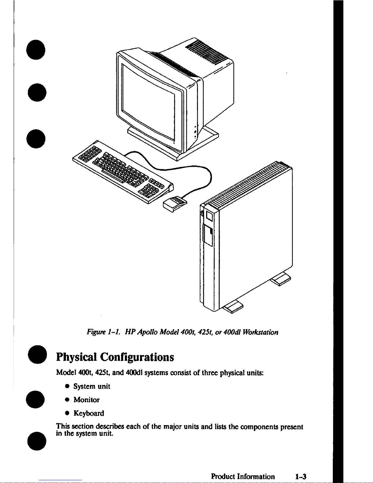
Figm 1-1. HP Apollo Model 400t, 425t, or 400dl Wokstatwn
Physical Configurations
Model 400t,42St,and 400dlsystemsconsistof three physicalunits
● System unit
● Monitor
. Keyboard
This seetion deseribeseach of the major units and Iislsthe components present
in the systemunit.
Product Information 1-3
Page 20
System Unit
The Model 4(NMand 425t systemunits wttains the followingcomponen~
● CPU board
. Memory boards
● Winchester disk drive@)
. Graphics controller board
● Optional network or HP-IB interface board
. Powx supply
The Model 400dlsystemunit contains the followingcomponenk
● CPU board
. Memory boards
. Graphi~ controller board
. Power
supply
The wercable used by the systemunit differs depending on the country of
r“
instaIatlon.
Monitors
The Model 400tand 425tsptems em be configuredwith the followingmonito~
. 19-inch, 1280x 1024monochrome monitor
. 16-inch, 1280x 1024color monitor
● 19-inch, 1280x 1024edor monitor
The Model 400dlsystemcan only use the 19-inch, 12S0x 1024monochrome
monitor.
Keyboards
Model400t,42St,or 400dlsystemsthat run the Domain/OS operating system
●
use the Domain low-profile keyboard.
Model 400t,42St,or 400dlsystemsthat run the HP/UX operating systemuse the
HP ITF keyboard.
The Domain keyboard connects to the rear of the systemunit via a coiledcord
that is permanently attached to the keyboard.
o
1-4
Product Information
Page 21
The ITR HP 46021Akeyboard connectsto the system unit via a detachable cord
which is labeled at both ends. One end of the cord is Ia&led with a single dot,
whichconnects to the HP-HIL port at the rear of the systemunit (also labeled
with a single dot). The other end of the cord is labeled with two dots, which
connects to the port at the rear of the ke board (alsolabeled with twodots). The
ikeyboard also has a connector for HP-H L devices,such as a mouse.
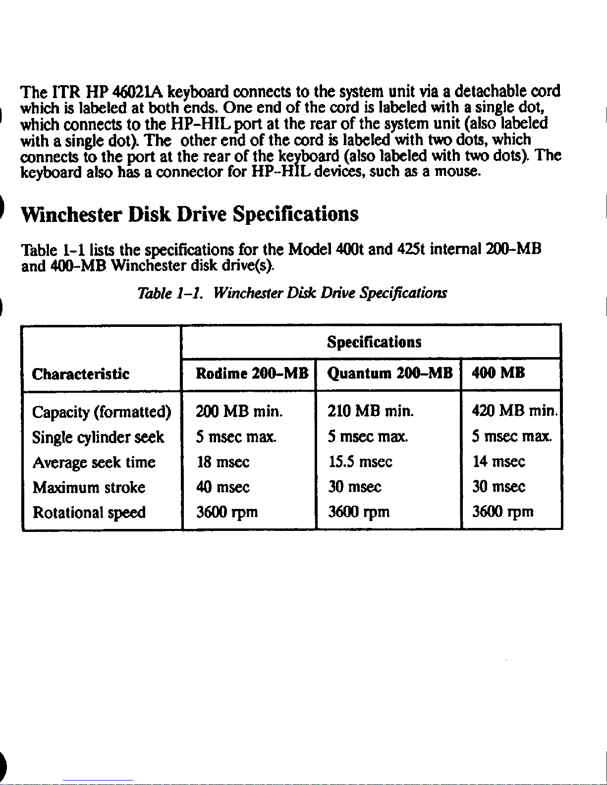
Winchester Disk Drive Specifications
Table 1-1 liststhe specificationsfor the Model 400t and 425t internal 200-MB
and 400-MB Winchester diskdrive(s).
T&le 1-1. Winchester D&k Dn”veSpecifications
Specifications
Characteristic
Rodime 200-MB
Quantum 200-MB 400 MB
Capacity(formatted)
2MlMB min.
210MB min. 420MB min.
Singlecylinder seek
5 msec max 5 msccmax.
5 macemax.
Averageseek time 18mace 15.5msec 14mscc
Maximumstroke
40 msec 30 msec 30msec
Rotational speed
3600rpm 3600rpm 3600rpm
Page 22
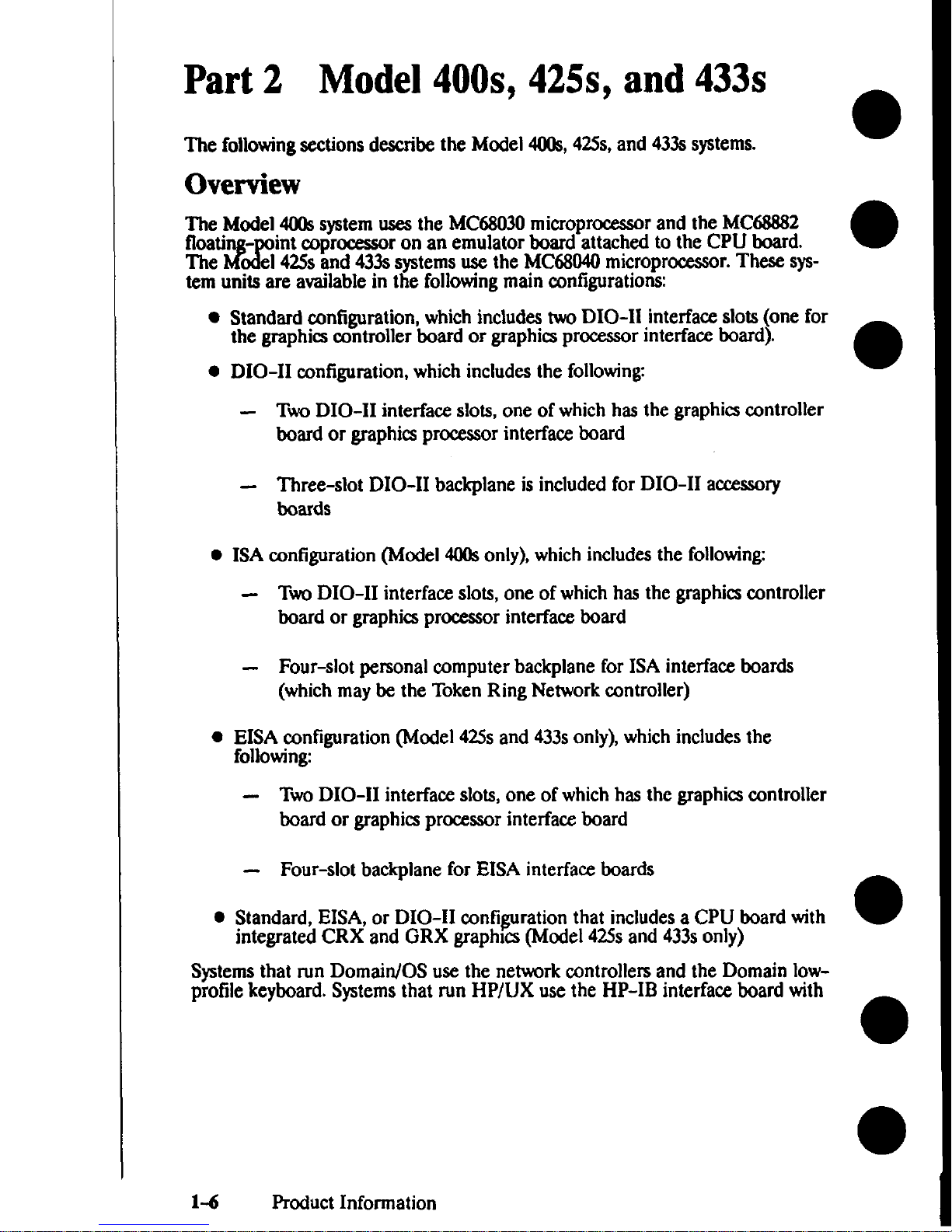
Part2 Model 400s, 425s, and 433s
The followingsections describe the Model 4Ms, 42Ss,and 433ssystems.
Overview
~wetiModel4(Kksystemusesthe MC6S030microprocessorand the MC6S8S2
2!
- int coprocessor on an emulator board attached to the CPU board.
The el 425sand 433asystemsuse the MC68040microprocessor.These system units are availablein the followingmain ccmfiguratiomx
● standard configuration, whichincludestwo DIO-11 interface slots (one for
the graphics controller board or graphicaprocessor interfau board).
. DIO-11 mnfiguration, which includes the following
– TwoDIO-H interface slots, one of whichhas the graphics controller
board or graphicsprocessorinterface board
- Three-slot DIO-11 backplane is included for DIO-11 acmsory
boards
.
ISA configuration (Model 4(XtSonly), which includesthe following
- TW DIO-H interface slots, one of whichhas the graphicscontroller
board or graphics processor interfa~ board
- Four-slot personal computer backplane for ISA interface boards
(whichmaybe the Token Ring Network controller)
. EISA ~nfiguration (Model 425s and 433sonly), which includesthe
following
- TW DIO-11 interface slots, one of whichhas the graphicscontroller
board or graphics
promaor interfacx board
– Four-slot backplane for EISA interface boards
● Standtid, EISA, or DIO-11 ~nfiguration that includesa CPU board with
integrated CRX and GRX graphics (Model 42Ssand 433sonly)
Systemsthat run Domain/OS use the network controlled and the Domain lowprofile keyboard. Systemsthat run HP/UX use the HP-IB interfau board with
1-6
Product Information
Page 23
the HP 46021Ake”board and other HP-HIL devices.Thes ternsalso can in-
●
J
r
elude one to four iskdrives.The displayoptions are the fo lowing
● Monochrome 19-inch, 1280x 1024,bit-mapped monitor and graphics
controller
. color I&inch, MfJ
xlt)24,bit-mappd monitor and graphics controller
●
● color1$)-inch,lmx1024,bit-mapped monitor and graphics amtroller
Model 4(Nk, 42Ss,and 433s systemsuse 4- and
16-MBmemory modules. These
modules are used in sets of two, allowingfor systemconfigurations of 8 MB to
128MB of main memory in 8- and 32-MB increments.
●
Built-in interfaces on the CPU board include the following
●
●
●
●
●
●
●
●
HP-HIL keyboard and input device interfam
Audio output jack for optional external speaker
Domain keyboard connector
RS-232 (expandable with the optional 3-port adapter for Domain/OS
systems)
802.3network (AUI or ThinLAN, jumper selectable on the CPU board)
Centronics Parallel Input/Output
SCSI
Monochrome GRX and Color CRX graphica interface (availableon the
optional CPU board with integrated graphics for Mcdel 42Ssand 433s
systems)
For systemsthat run HP/UX, you can eonfigure parameters for the RS232,802.3
network, Centronics parallel, and SCSI interfaces byusing the Boot ROM I/O
configuration program. (Refer to Appendix C for information about using the
configuration program.)
Figure 1-2 shows a typical Model 4(Ms,
42Ss,or 433s system.
Product Information 1-7
Page 24
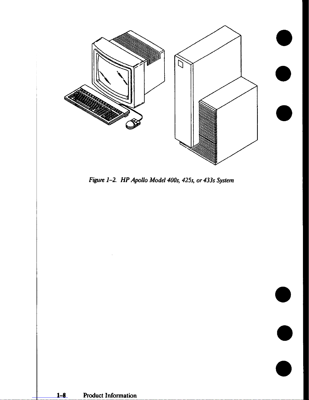
Figure1-2. HP Apollo Model 400s, 425s, or 433s System
1-8 Product Information
Page 25
AccessoryCards/Boards
The followingsections list the available DIO and AT-compatible accessory
boards that are available for Model 4(N)s,42Ss,and 433ssystems.
Supported DIO Accessory Boards
The followinglistshows the DIO-IIaccesso~ boards sup rtedin Mode1400s,
425s,and 433ssystemunits. HP-UX sup rts all of these
# ‘ards; ‘“ma’n’o’
supports only the HP 98643ALAN inte ace bard.
. HP 36941A X.25/3tJ0 Link
.
HP 91225AHP-HIL/Audio Interface
. HP 98286AHP-UX DOSCoprocessor
. HP 98622A16-Bit Parallel
. HP 98624AHP-IB Interface
● HP 98628ADatacomm Interface
. HP 98638A8-Port Multiplexer
● HP 98642A4-Per-tMultiplexer
● HP 98643ALAN Interface
● HP 98644ARS-232 Interface
. HP 98646AVMEbus 16-Bit Interfa&
. HP 98649ASDLC Interface
● HP 98658ASCSI Interfaee
● HP 50692ASRM Interface
Page 26
Supported AT-Compatible Accessory Boards
Model 40fk,42Ss,and 433ssystemunits that run Domain/OS support the following AT-compatible aeeeasoryboards
● A-ADD-PCC Domain DOS Co-processor
● A-ADD+PE Serial/Parallel Interfaa
● A-MT-ATR Apollo Token Ring
. A-NET-Ill? IBM Token Ring
● KIT’-ATBUS-CENT Centronics Interface
● A-ADD-SCAT X.2.5Serial Interfam
Physical Configurations
Model40% 425s,and 433ssystemsmnsist of three physicalunits the system
unit, the monitor, and the keyboard. This sectiondescribeseach of the major
units and lists the components present in the systemunit.
System Units
l%e systemunit isavailablein three versions
● Standd Model 4(Kk,42Ss,and 433s systemshave the followingcompo-
nents
Powersupply
Motherboard with two DIO-11slots
CPU board with attached emulator board and memory modules
Graphics controller or interface board
Massstorage deviees
Fans
●
An optional HP-IB interface board mayalsobe included.
DIO-11systemshave an additional 3-slot DIO-11 backplane.
ISA Model 400ssystemshave an additional 4-slot ISA backplane that in-
etudeasupport for the Apollo Token Ring network hoard.
1-1o
Product Information
I
I
Page 27
● EISA Model 42Ssor 433ssptems have an additional 4-slot EISA back-
plane that includessupport for the Apollo Token Ring network board.
. Mode]
425s and 433ssystemswith a newer chassisdesigncan use the HP
A1467AVMEbus Expander, which is an external chassisthat holds up to
eight VMEbus application cards. The VMEbus Expander connects to the
system’sVMEbus through a connector on the left side (facing)of the sys-
tem unit.
Monitors and Graphics ControI1ers
Model 400s,42Ss,and 433ssystemscan be configuredwith one of several monitors. They can atso be configured with a gra hits controller board or a graphics
Lprocessor connected to a graphics interface ard in the systemunit.
Monitors
Su ported monitors on Model 400s,425s,and 433sworkstationsinclude the
1’
fol owing
. HP A1097A/A1097Bhigh-resolution 19-in. color monitor
. HP 98754Ahigh-resolution 19-in. color monitor
. HP
● HP 98774Ahigh-resolution 19-in, monochrome monitor
98789Ahigh-resolution 16-in. color monitor
Graphics Display Controllers
Sup rted graphicspromssors on Model 400s, 42Ss,and 433sworkstations in-
PCIUe the following
● HP A1096AMonochrome VRX controller board
● HP A1416AColor VRX controller board
● HP 987t)5APersonal VRX P2 graphicsprocessor
● HP 98’705BPersonal VRX P3 graphicsprocessor
● HP 98735Allrbo VRX T1 graphicsprocessor
● HP 98736A‘fbrbo VRX T2 graphicsprocessor
● HP 98736Bllwbo VRX T3 graphics prmssor
Page 28
Keyboards
Model 400s,42Ss, and 433ss terns that run the Domain/OS operating system
r
●
use the Domain low-profile eyboard.
Systems
that run the HP-UX operating systemuse the HP 46021Bkeyboard.
The Domain keyboard connects to the rear of the systemunit via a coiled cord
that ispermanently attached to the keyboard.
●
The HP 46021Ake board connects to the systemunit via a detachable cord
Lwhichis labeled at th ends. One end of the cord is labeled with a single dot,
whichconnects to the HP-HIL port at the rear of the systemunit (also labeled
with a single dot). The other end of the cord is labeled with twodots, which
mwcts to the port at the rear of the ke board (also labeled with two dots).The
{
keyboard atsohas a connector for HP-H L devices,such as a mouse.
●
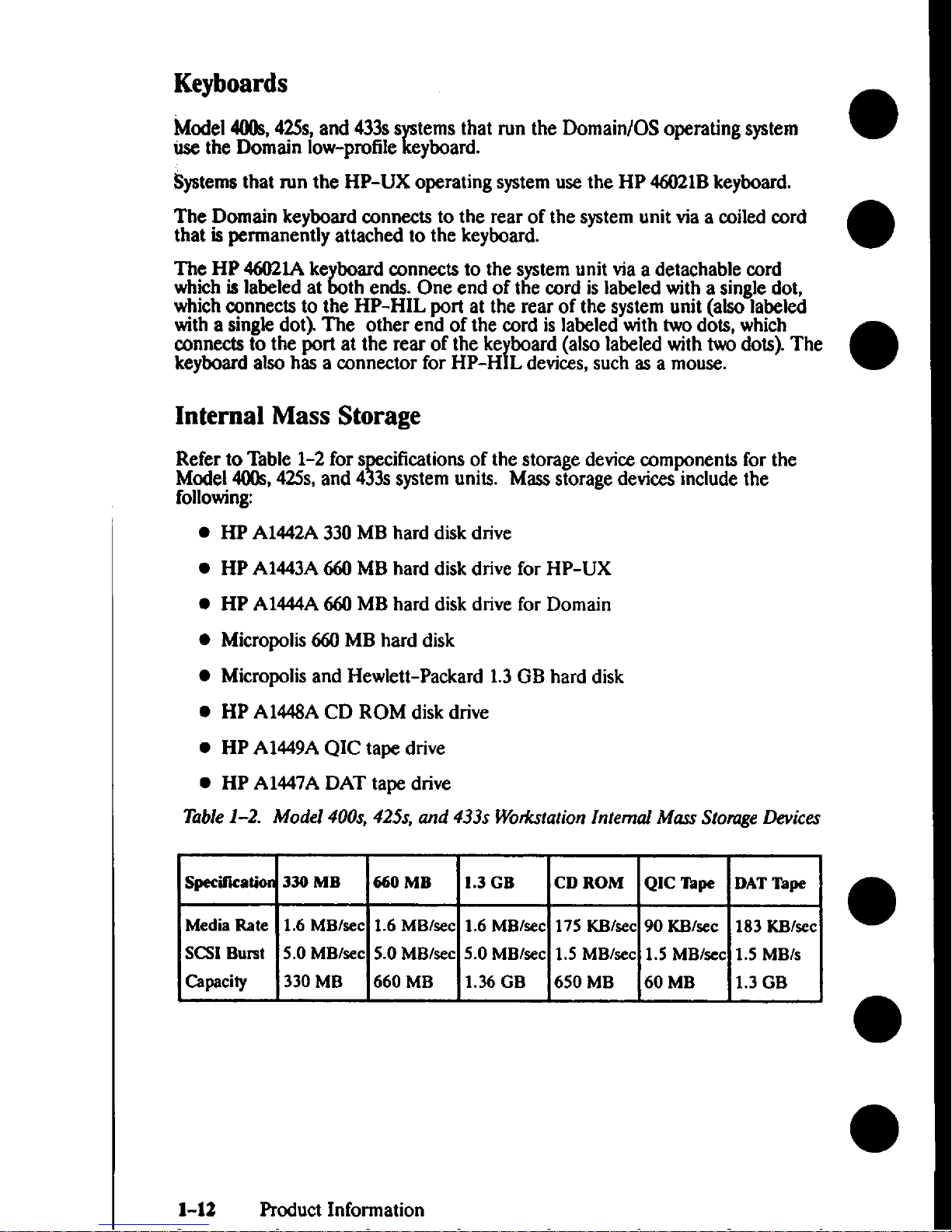
Internal Mass Storage
Refer to Table 1-2 fors
F
ificationsof the storage devicecomponents for the
Model4(0s, 42Ss,and 4 3s systemunits. Mass storage devicesinclude the
following
●
●
●
●
●
●
●
●
HP A1442A330MBhard disk drive
HP A1443A660MB hard disk drive for HP-UX
HP A1444A660MB hard diskdrive for Domain
Micropolis660MB hard disk
Micropolisand Hewlett-Packard 1.3GB hard disk
HP AM48A CD ROM disk drive
HP A1449AQIC tape drive
HP A1447ADAT tape drive
Table 1-2. Model 400s, 425s, and 433s Wodatation Internal Mass Stonrge Devices
Specification
330 MB
660 MB 1.3 GB CD ROM
QIC Tape DAT Taps
Media Rate 1.6 MBlsec
1.6 MBkec
1.6 MBlsec 175 KB/sec
90 KB/sec 183
~/SCC
●
SCSIBurst 5.0MBlsec
5.0
MBISCC
5.0 MBlsec 1.5 MBtsec
1.5 MBlsec 1.5 MBIs
Capacity
330 MB 660 MB
1.36 GB
650 MB
60 MB
1.3 GB
●
1-12 Product Information
Page 29
Environmental/
Installation/PM 2
Model 400t, 425t, and 400d1 System Units
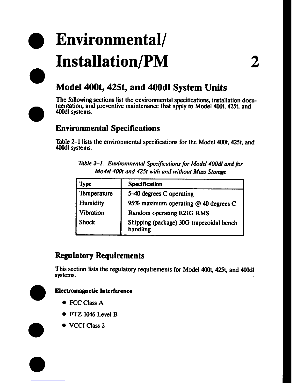
The followingsections list the environmental specifications,installation documentation, and preventive maintenance that apply to Model at, 425t,and
400dlsystems.
Environmental Specifications
Table2-1 liststhe environmental specificationsfor the Model 400t,425t, and
4(M)dlsystems.
Table2-1. Envinmmental Sjiecification.sfor Model 400dl and jbr
Model 400t and 425t with and without Mars Stomge
Q*
Specification
Temperature
5-40 degrees C operating
~
Shlppmg (package) 30G trapezoidal bench
Regulato~ Requirements
This section lists the regulatory requirements for Model 400t,425t,and 400dl
systems.
Eketromagnetic Interference
● FCC c]= A
● FTZ 1046Level B
c VCCI Class 2
Page 30
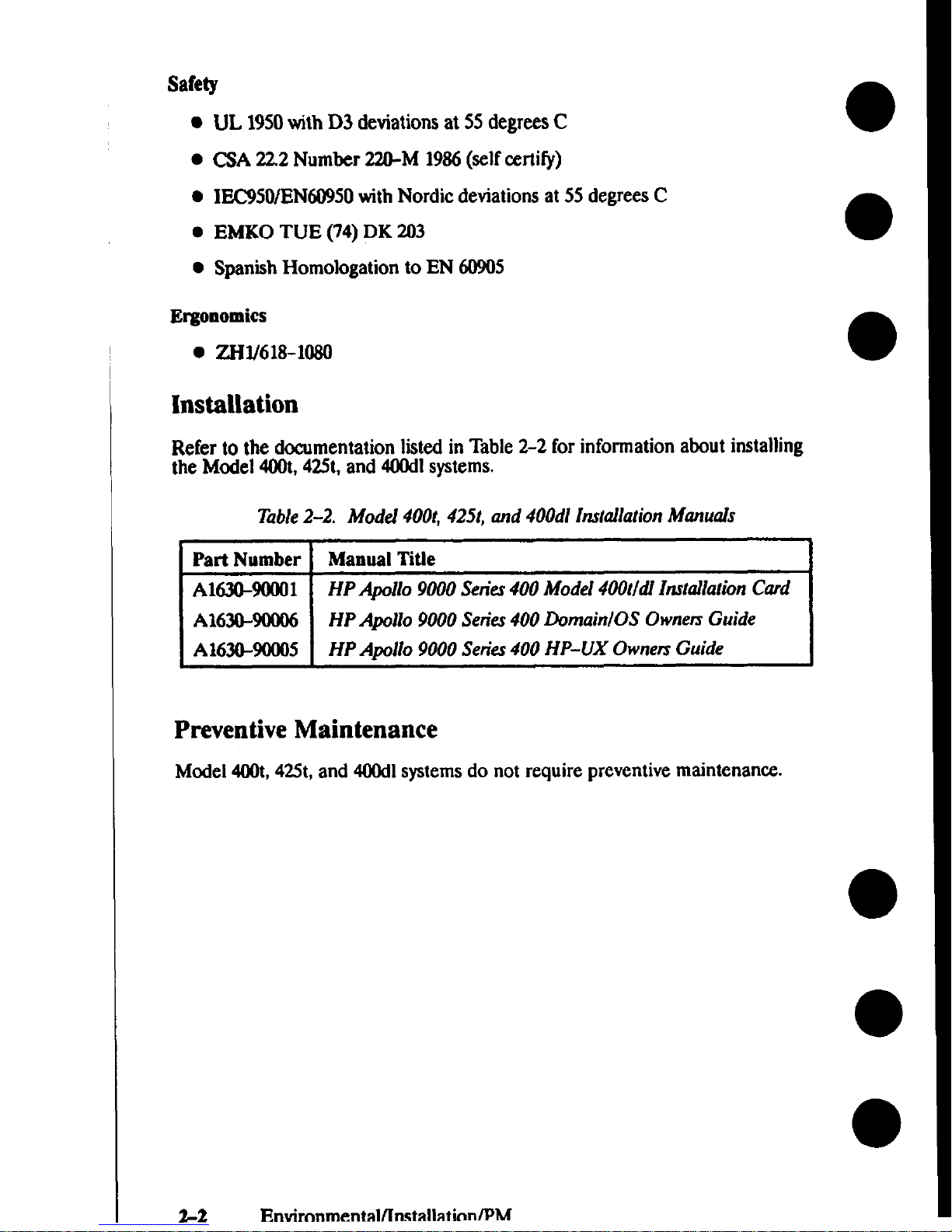
Safety
UL 1950with D3 deviations at 55 degrees C
CSA 222 Number 220-M 1986(selfcertify)
IEC950/EN60950withNordic deviations at 55degrees C
EMKO TUE (74) DK 203
Spanish Homologation to EN 60905
Ergonomics
● ZIW618-108O
Installation
Refer to the documentation listed in Table 2-2 for information about installing
the Model 400t,425t,and 400dlsystems.
Table2-2. ModeJ 400t, 4251, and 400dl ttzr(ailation Manuals
Part Number
Manual Titte
A1630-90001
HP Apollo 9000 Serie.r400 Model 400t/dl InstaJIa!ionCard
I A1630-9tN06 \ HPApolIo 9000 Series400Dornain/OS OrvnefsGuide
HP Apollo 9000 Series400 HP-UX Ownen Guide
Preventive Maintenance
Model400t,
42St, and 400dlsystemsdo not require preventive maintenance.
2-2
Envircmmental/lnstallatinnlPM
Page 31

Model 400s, 425s, and 433s System Units
The followingsections list the environmental specifications,installation dcxumentation, and preventive maintenanu that applyto Model 4tM)s,42Ss,and 400s
systems.
Environmental Specifications
Table 2-3 lists the environmental specificationsfor the Model 400s,425s,and
433ssystemswith internal massstorage devices.
Table2-3. Envinmmenkd Spec@cationsjbr Model 400s, 425s, and 433s
System Units With Mars Stotuge
‘IbM I snaoif’imtifi”
‘JP
wy . . . . . ...””-
Temperature 5-40 degnxs C operating
Humidity
80% maximumoperating @40 degrees C
Vibration
Random operating 0.21G RMS
Shock
Shipping (package)30Gtrapezoidal bench
handling
Table 2-4 lists the environmental specificationsfor the Model400s,42.5s,and
433ssystemswith no internal mass storage devices.
T&le 2-4. Environmental Specifications for Model 400s, 425s, and 433s
System Units Without Mass Storuge
Specification
Temperature
O-55degrees C operating
Humidity
I
9S% maximumoperating@ 40 degrees C
Vibration
Random operating 0.21G RMS
Shock
I
Shipping (package)30G trapezoidal bench
handling
Regulatory Requirements
This section lists the regulatory requirements for Model4(K)s,425s,and 433s
systems.
Environmental/Installation/PM 2-3
Page 32

Electromagnetic Interference
● FCC ClassA
● nZ 1046Level B
● VCCI class 1
Safety
● UL 1950with D3 deviations at 55degreesC
. GA 22.2Number 220-M 1986(selfeerti$)
● IEC950/EN60950with Nordic deviations at 55 degrees C
Laser Safety
European Harmonized Document 194
IEC 825
VBG 93
BS4803Part II
21CFR Chapter 1Sub-Chapter J
Ergonomics
● zH1/618-lo80
Installation
Refer to the documentation listed in Table 2-5 for information about installing
the Model 400s,425s,and 433ssystems.
T&le 2-5. Model 400s Installation Manuals
Part Number Manual TitJe
A1421-!HXIO1
HP Apollo 9000 Serie.r400 Installation Guide
A1630-90006
HP Apollo 9000 Series 400 Domain(OS Ownets
Guide
A1630-90005
HP Apollo 9000 Setitv 400 HP-UX Ownen Guide
Preventive Maintenance
Model4(K)s,425s,and 433ssystemsdo not require preventive maintenance.
2-4 Environmental/Installation/PM
Page 33

3
This chapter rovideaconfiguration information for Series 400workstations and
workstation I&Us.
Workstation and System Unit Configurations
Refer to the HPAPoI1o 9000 Series400 Suppoti Mattir for a @replete listof sup-
ported aceeasories,peripherals, and operating systems.
FRU Configurations
The followingsubsectionsdefine the jum r and switchconfi~rations for sys-
tem boards and internal storage devices.Refer to the appropriate figure for mnfiguration information for the FRU that you’re replacing.
NOTICE:
Series 400systemunits do not use SCSI bus terminators on internal storage drives.No third-party
internal storage devieescan use terminator bexxuse
other storage drives may not function properly. Refer to the third-party massstorage device’sdwumentation for instructions.
CPU Board Configurations
Figure 3-1 showsthe jumper locations for Series 400CPU boards without inte-
~ted graphia. Figure 3-2 show the “um~r locationsfor the CPU board with
i
integrated graphica.Refer to Table 3- to find the clockspeeds of these CPU
boards for the various Series 400systems.
Page 34

o
r
------A— ---- J .--—
I
mnoael 4UUS, 4z5s, ana433s
CPU Board
-c
/~
Clock Speed Jumper ●
(25 MHz Setting Shown)
/u\
Figwe 3-1. Jumper Conjiguratiorarfor CPU Boards Without Integrated Grqphics
3-2
Configuration
Page 35

n
811
GraphicsSelectionJumper
\
(ColorGraphics
Setting)
/
EtherLAN
p \lc)c)oooooclool)
=il
1
Jumper Is shown In AUI
position.
)
Clock Speed Jumper ●
(25 MHz Setting Shown)
● Refer to Table3-1 for correct jumper setting.
Fi@te 3-2. Jumper Con&umtions for the CPU Board with Integmted Gmphic.s
Table3-1 showsthe jumper settings for the clockspeed of the different Series
400system models.
Configuration
3-3
Page 36

Table 3-1. Jumper Configurationsfor CPU Board Clock S’d
Model
4c#dlMOOt
425tJ425s
425t1425s
425s
433s
433s
Integrated
Graphics?
No
No
No
Yes
No
Yes
EDC Label
Assy Rev
N/A
NIA
NJA
NIA
Jumper Setting
25 MHz
33 MHz
25 MHz
25 MHz
33
MHz
33 MHz
For Model 425tand 425ssystems,the clocks
Fd ‘erhon ‘hewmb’yre’
sion listedon the CPU board’sEDC label. I entlfy t e assemblyrevwon number at the followinglocation on the EDC label
EDC label format
AssemblyRevisionNumber
=r(fo’”amp’e’n
Xxxx-xxxx
MADE
IN XXXX
.
●
3-4 Configuration
Page 37

HP A1416A VRX Color Graphics Controller
Figure 3-3 showsthe default switchconfiguration for the VRX Color Gra hica
r
Controller board. For alternative switchconfigurations, refer to the HP A 416A
Gmphics Intetfize Familia&tion Guide.
~’J-
1
Figure3-3. HP A1416A Color Graphics Controller Switch Conjigumtion
Page 38

HP A1096A VRX Monochrome Graphics Controller
Figure 3-4 show the “umperlocations for the VRX Monochrome Graphica
I
●
Controller board. Tabe 3-2 liststhe jumper configurations.
Fi~m 34. VRX Monochrome Graphics ContmllerJumpem
Table 3-2. Jumper Conjigumtions for YRX Monochrome Conmdler
Address (Hex)
1oooooo
14000Ct0
18000tM
lcuoooo
3-6
Configuration
Page 39

802.5 Network Controller-AT
Figure 3-5 shows the standard jum
r
r configuration for the 802.5Network Con-
troller-A’I Figure 3-6 shows the a temate jum r configuration, Use the stan-
dard jumper eonfi$uration for the first or only
L
5 controller in the system.
Use the alternate urn r configuration for a semnd 8025 controller, or for the
I “r
only8025 control er ] another option board in the systemuses the standard
configuration parameters.
Memory
Addrese
1 = OFF
2 = 98000
3=84000
4 = E8000
(2
MEM
Ual
0000
0000
1234
\
J
n
9 me
—
o
0
P’‘‘n”
I RRUPT
000000
00 000000
000000
00
000
w
705
3 1514121110
J
2=280
3 = 2A0 1‘;R1
4=2=0 2= SEC
d!—nec
/
* =
urr
la
= Plasticjumperinstalledoverthe pinsintwocolumns
Figure3-5. Standard 802.5 Netwods Controller-AT Jumper Con)igumtion
Configuration 3-7
Page 40

•1
/ DRQ/lRQ \ / [ 1:
x /,% ‘
(‘ ‘~’“u’
Cp)
>000
D
INTERRUPT
iv
123 ~0
00 000000
oo~ooo
m
000
00 00
00 00000
7 e15
~ .. . . .. .
J
A
1=280 ~
2=290
3=2A0 l=pRl
4=2C0 2= SEC
3 = OFF
la
= Plssticjumper installedoverthe pinsintwooolumns
FiWte 3-6. Alternate 802.5 Netwok Controller-AT Jumper Conjigurution
Page 41

Apollo Token Rhg Network Controller-AT
F$ure
Rmg Network Controller-AT i re 3-8 showsthe alternate jumper settings for
the second Apollo Token Ring etworkController-A’E
3-7 showsthe standard “umpersettingsfor the first or only Apollo Token
&
NOTICE: Jumper W11is factoryselected;do not remove.
‘t-’+=
WI ●= W2 ●= 1/0AddrassSpace220- 23F,320- 33F
Fi@we3-7. Apollo Token Ring Network Controller-AT Jumper Settings
Page 42

WI1
\
00-
W1 ~ W2~@ 1/0AddressSpace 240- 25~340- 35F
Figzus3-8. Alternate Apollo Token Ring Netwotk Controller-AT Jumper Settings
●
●
●
3-1o
Configuration
Page 43

,
PC Coprocessor Board
Figure3-9 shows the standard jumper confi~rations for the PC Coprocessor
board. Fi@rm&O shows the alternate jumper configurations for the PC
Coprocessor .
IRQ11
DRQ5
Base
=
Jumper Installed
Address
1111111llullll lllllllllllr
Base
Address
Figute 3-9. PC Coptoce-ssorStandard Jumper Conjigumtions
IRQ11
DRQ7
[
II
\
●
●
= JumperInstalled
1111111ulllllllllllllllr
Figure3-10. PC Copmce.rsorAlternate Jumper Conjlgumtion.r
Page 44

Rodime 200 MB Disk Drive
Figure 3-11 she% the jumper configurations for the Rodime 200 MB Winchester Disk Drive.
RodlmeDrive
(Rear View)
k
o
● ● MSB
d
● 0
●● LSB
● ● Auto Spin Up
.
● Parity
Jumpers
Tsrget ID
(Highest IDisboot devioe)
H
MSB
6 =
Default for Drive O
● 0 LBB
1111111
MSB
5 = Defautt for Drive 1
LSB
~ MSB ~
● 0 LSB
● 0
H
USB
3
LSB
, ● MSB
EE82
● ● I.SB
● ● MSB
&LBB 1
Auto Spin Up
Jumper = Drivespins up at power on.
No Jumper = Drivespins up when host sends start unit command.
Parity:
Jumper =
Paritychecking enabled.
No Jumper = Parity checking disabled.
Figure 3-11. 200 MB Rodime WinchesterDirk Dn”ve
3-12 Configuration
Page 45

Quantum 200 MB and 400 MB Disk Drive
●
Figure 3-12 shows the jumper confi
Y
rations for the 200 MB and 400MB Quan-
tum diskdrives.If present, remove t e terminators from the drive.
~
r
0
II
\
Terminators
Ill
~~~ 5. Defautt for DrWe 1
~ MSB ~
●0 LsB
●0 MSB ~
E
LSB
●* Mss
02
●0 Lss
●0 Mss
fi LSB 1
Jumpers Target ID
n
[Highest ID Is boot devlcs)
MSB
6 = Default
for Drive O
●● Lss
●
a
●
Figure3-12. 200 MB and 400 MB Quantum Disk Drive
Configuration
3-13
Page 46

Hewlett-Packard 400 MB Disk Drive
~ re 3-13 showsthejumperconfigurations for the 400MBHewlett-Paeicard
r
dis drive.If present, remove the terminators from the drive.
Jumpers Target ID
(Highest ID is boot device)
H
MSS
6 =
Default for Drive O
●● LsB
#
MSS
5 = Default for Drive 1
LSB
~ MSB ~
●● LsB
●● MSB
E
3
LeB
●● MsB
=2
●● LsB
●. MsB
O LSB 1
rerminstors
Front View
Bottom View
“o”
“o”
m
II
u
u
Figure3-13. 200 MB and 400 MB Quantum Disk Drive
●
●
●
3-14
Configuration
Page 47

HP 1442A 330 and HP A1443A 660 MB Disk Drive
●
Figure 3-14 showsthe jumper configurations for the HP 330MBand 660MB
diskdrives.
RearView
●
●
M
Not used
o
= 1, Jumpered o
= O,Open
Pin
Set
Function O= Open, 1= Jumpered
1 Reserved for future use, normally 1.
2 Drive initiation of SDTR message
O - Inhibit initiation of SDTR message.
1 = Enable initiation at power on
and RESEX
3 Pm@’:
O = Parity checking is disabled.
1 = Parity checking is enabled.
4 Auto spin up:
O = Drive does not spin up until host
sends start unit command.
1 = Drive automatically spins up at
power on.
S-7 SCSI address; 7 is LSB.
567
Address
567 Address
000
0
100 4
001
1 101 5
010
2 110 6
011
3 111 7
FiW~ 3-14. HP 1442A 330 and HP A1443A 660 MB Disk Drive
Configuration 3-15
Page 48

Micropolis 660 MB and 1.3GB Disk Drives
Fi re 3-15 shovtsthe jumper confi rations for the Micro@is 660 MB and 1.3
l!’
G~d~k drives.If prescn+ remove t e SCSI terminator from the drive.See
Figure 3-16 for the Ioeatlonof SCSI terminator.
●
Mlcropolis 660-MB and 1.3-GB Drive
(Rear View)
I
.........
.........................
.........
@lo””’””””’”””””””””””””””””Jl@q
SCSI Address JumperPins
Address
Address
Target ID
Jumpers
Target ID
Jumpers
o
0
000
000
1
m
00
00
2
Clzl
00
00
m
o
3
0
4
K1
00
00
5
11111
0
0
6
m
o
0
7
m
Figure3-15. MictvpoIi.s 660 MB and 1.3 GB Dirk Drives
3-16
Configuration
Page 49

Mlcronolls 660-MB and 1.3-GB Drive
.
(Bottom View)
r
,
I
El
0
‘o
ill
El
1111
‘o
~
=i=
Pack Terminator
Fijpoe 3-16. M~topolk 660 MB and 1.3 SCSI TenninutorLocations
Configuration
3-17
Page 50

Hewlett-Packard 1.3 GB Disk Drive
FIgure3-17 showsthe jumper configurations for the Hewlett-Paekard 1.3GB
Hard Disk Drive. If present, remove the SCSI terminators from the drive.See
Figure 3-18 for the hxation of SCSI terminators.
Hewlett-Packard 1.3-GB Drive
(Rear View)
.. .. ..... ................
.. .. ....................,
SCSI AddressJumperPins
Address
Address
Target ID
Jumpers
Target ID
Jumpers
o
1
2
3
n
000
000
cl
00
00
ml
00
00
m
o
0
4
III
00
00
5
Elll
o
0
6
m
o
0
7
m
Fi@ut 3-17. Mictopolis 660 MB and 1.3 GB Disk Drive
3-18
Configuration
Page 51

Hewlett-Packard 1.3-C3B Drive
(Bottom View)
❑
•1
•1
‘*’
Single In-1ineTerminators
Figwe 3-18. Hewlett-Packard 1.3 GB SCSI TerminatorLocations
Page 52

HP A1449A 0.25-in. QIC 60-MB
Figure 3-19 showsthe jumper configurations for the QIC 60-MB Tape Drive,
Rear View
00
= O,Open
.Immool .
w
Pin
Set
Function: 1= Jumpered, O= Open
A
P
D
SCSI ID address Ois LSB
124 Address
124 Address
000
0
001 4
100
1
101 5
010
2
011 6
110
3
111 7
Parity
O = Pantychecking is disabled.
1 = Parity checking is enabled.
Disconnect Size Ois LSB
100 I 4K
I 101
010 6K
011
I11OI
8K 1111
Figuts 3-19. HP Al449A 0.25-in. QIC 60 MB T* Drive
●
●
3-20 Configuration
1
Byte Size
12K
16K
24K
Q?!d
Page 53

HP A1448A CD-ROM Drive
Figure 3-Xt showsthe iumper configurations for the CD-ROM drive.
Rear View
!
=
Switch Up
Switch
Function and Settings
1,2,4
SCSI ID address; 1 is LSB
124 Address
124 Address
000 0
001 4
100 1
101 5
010 2 011 6
110 3
111 7
Pm Parity
O = Parity checking is disabled.
1
= FWity checking is enabled.
ARBT titration:
O = Arbitration is disabled.
1
= Arbitration is enabled.
TEST
Test: For repair facility use only.
FiWm 3-20. HP A1448A CD ROM Drive
Page 54

HP A1447A DAT Tape Drive
Figure 3-21 showsthe jumper eontigurations for the DAT tape drive,
I
r
1
I
I
I
Bottom View
PT21O
I
= 1, Jumpered
Side
View
n=n
o
= O,Open
o
Pin
Set
P
T
2-0
+
+ f-
Function: O= Open, 1= Jumpered
Parity:
O = Panty checking is disabled.
1 = Parity checking is enabled.
Power supply voltage to the on-board
terminating resistorx
O = Terminator power is enabled.
1 = Terminator power is disabled.
SCSI address; Ois LSB
210
Address
210 Address
000
0
100
4
001
1 101
5
010
2
110
6
011
3
111
7
Vertical mounting, eject button down
Horizontal mounting, tape slot up
Vertical mounting, eject button up
Figure3-21. HP A14#7A DAT Tqe Drive
3-22
Configuration
Page 55

Series 400 Systems EEPROM
The EEPROM stores the node ID?the network priority, and at SR1O.3PSK8)
L
the bus clockspeed used by Domam compatibles terns.The EPROM also
C?E
stores the I/O configuration information used b P-UX compatible systems.
To retain this information when you replace a PU board: transfer the original
EEPROM to the new CPU board. If you replaee a defectwe EEPROM, use the
EEPROM part numbers listed in Chapter 7 to order a replacement EEPROM
with the same node ID as the original EEPROM.
CAUTION Use an anti-static strap to prevent electrostatic dam-
age to the EEPROM. Electrostatic damage ean de-
stroy the EEPROM or erase configuration informa-
tion from the EEPROM.
This section e Iains how to remove the EEPROM from a CPU board beeause
Ythe EEPROM as failedor because you are replacing the CPU board. Refer to
the appropriate subsection for the type of procedure that you are performing.
lkansferring an EEPROM to a Replacement CPU Board
When replaeing a CPU board, remove the EEPROM from the failed CPU
board and install it in the new/exchangeCPU board. Refer to Fi re 3-22 for
F
the Ioeation of the EEPROM on a Model 400t,425t,and 400dl PU board. Refer to Fi re 3-23 for the location of the EEPROM on the two typesof Model
@O##fi and 433sCPU boards. Use an EEPROM puller to remove the
Page 56

Figure3-22. &moving the EEPROM (Model 400t, 425t, and 400aY)
●
●
●
3-24 Configuration
Page 57

—
CPU Board with
Integrated GraphIce
/
Fi@te 3-23. Removing lhe EEPROM (Model 400s, 425s, and 433s)
Configuration
3-25
Page 58

Replacing a Defective EEPROM
Fi re 3-24 showshow to remove the EEPROM from the Model 4tHlt,425t,or
&
Isystemunit without removing the CPU board. To replace an EEPROM in
a Model 4tXk,42Ss,or 433ssystemunit, you must remove the CPU board. Refer
to the appropriate CPU board in Figure 3-23 for the location of the EEPROM.
Figure3-24. Rephzcingthe EEPROM in a Model 400t, 425t, or 400dl
3-26
Configuration
Page 59

When you replace a failed EEPROM, or if the EEPROM has been corrupted,
perform the appropriate bulleted step
● For systemsthat use Domain Compatible mode, perform the following
steps
1. Use the Boot ROM configuration program to select Domain Compatible mode, the primary network for the system,and at SR1O.3
PSK8,the bus clockspeed.
2. Run the Chuvol utility.
. For systemsthat use HP-UX Compatible mode, use the 13mtROM
eonfiguration program to perform the followingsteps
1.
2.
3.
Seleet HP-UX Compatible mode.
Set the Auto SystemSelect and 1/0 Configuration modes to their
previousconfigurations.
Change the LAN ID in the cluster configuration file to that of the
new EEPROM.
NOTICE:
Because the EEPROM stores the node ID, application software for Domain/OS systemsthat relyon
the node ID for licensingrequirements may not
function after you replace the EEPROM.
Configuration 3-27
Page 60

~onflguring the EEPROM on HP-UX Compatible
Mode Systems
This
seetion explainshow to confi re the EEPROM for the boot mode, auto
P
systemselect, and integrated inter aces for HP-UX systems.
Boot Mode Selection
Perform the followingsteps to selectthe boot mcde for an HP-UX system:
1.
2
3.
4.
5.
6.
7.
8.
3-2a
If you have alreadybooted an operating system,logout and stop any
user processes
If not, go on to step 2
If the systemunit isoperating in HP-UX mode, reset the systemunit
and get the power-up display.Then, when the keyhoard is identified,
type the followingcommand:
C <Return>
If the systemunit is operating in Domain mode, reset the systemunit
and type the followingeomand
CF <Return>
From the Configuration Control Menu, type the number key command
to get the Boot Mode SelectionMenu:
&q <Return>
From the Boot Mode SelectionMenu, type the number key for the
Boot Mode you want to use.
key <Return >
From the Boot McxieSelection sub-menu, type the command to make
the selection temporaV (T) or permanent (P]
key < Return>
To execute the menu, type the followingcommand
E <Return>
The system unit resets and goes into the boot mode you have selected.
Configuration
Page 61

●
Auto System Select Mode for HP-UX Compatible
Mode Systems
Perform the followingsteps to use the Auto SystemSelect mode
●
1.
●
3.
4.
5.
6.
7.
●
●
●
If you have already booted an operating system,logout and stop any
user processes
If not, go to step 2
Reset the system unit and get the power-up display.Then, when the
keyboard is identified, type the followingcommand
C <Return>
From the Configuration Control Menu, type the followingcommand to
get the Auto SystemSeleetMenu:
2 <Return>
From the Auto System Select Menu, type the number key for the option
statusyou want to change
&q <Return>
To execute the menu, type the followingcommand
E <Return>
If you set the menu to selecta system,the systemunit resets and dis-
playsthe availableoperating systemsin the upper right-hand comer of
the dkplay. Select the operating systemyouwant to bed by typing the
number and letter key for the system:
key
key c Return>
If you set the menu to store the selected system, the path to that operating system isstored. The next time the systemunit is turned on, that
operating system boots.
Configuration 3-29
Page 62

I
Internal 1/0 Configuration Mode for HP-UX Compatible
Mode Systems
This seetion explainshowto configure the built-in interfacesunder Bmt ROM
control by usingkeyboard inputs.
Default and Optional Configttmtions
Table3-3 liststhe availableoptions for configuringthe built-in interfaces.
Table 3-3. Built-In Interjhce Defult Configurations
Interface
Configuration Function
Default Options
Optional HP-IB
Select Code (cannot be changed)
7
None
SystemController Ya No
RS-232
SeleetCode
9
0 to 31
Remote/Local
sys.unit shipped with kbd.
Local
Remote
sys.unit shipped without kbd.
Remote Local
Interrupt Level
3
3t06
Modem Enable Yes No
Sal
SelectCode 14 0 to 31
Interrupt Level
3 3t06
BusAddress
7 oto7
Parity
Yes
No
Thin/AUI LAN
S&@ Code
21
0 to 31
Interrupt Lad
5 3t06
HP Parallel
SelectCede
12
0 to 31
Interrupt Level
3 3t06
3-30
Configuration
Page 63

●
Changing1/0 Configuration
Perform
1.
●
2
●
3.
4.
5.
6.
7.
8.
@
9.
the followingsteps to change an interfatx configuration
If you have already booted an operating system,logout and stop any
user processes. If not, go on to step 2.
Reset the systemunit. When the power-up display,identifiesthe keyboard, type the followingcommand
C <Return>
From the Configuration Control Menu, type the followtngcommand to
displaythe I/O Configuration Menu:
1 <Return>
From the I/O Configuration Menu, type the number for the interface
that you want to eontigure
key <Return>
T~ the number for the feature that you want to change
key <Return >
T~ the number or letter key(s)to change the feature
keyfs)<Return>
Exit the selected interfaee menu by typingthe followingcommand
X <Return>
Typethe appropriate letter key to store the newvalues,store the de-
fault values,or abort and not make any chang=
key <Return >
When you turn on the systemunit for the first time and the Configura-
tion Control Menu appears, type the followingcmmmandto enter the
Auto SystemSelect Mode
2 <Return>
10.If you have already selected an operating system, abort the menu without making changes by typing the followingcommand
●
A <Return>
Page 64

Configuring the EEPROM on Domain Compatible
Mode Systems
This section deseribes how to select Domain Compatible mode, netwmk riority,
●
and clockspeed for systemsthat run Domain/OS. The systemEEPRO#s.tores
this information.
●
●
●
✎
Youmustconfigure the EEPROM if any of the followingevents occtm
Youhave replaced the systemEEPROM with a
new EEPROM that is
●
not configured correctly
The EEPROM mode configuration iscorrupted, possiblybecauseof
electrostatic discharge when handled
without using a grounding strap.
●
A Domain/OS systemships from the factorywith an incorrectlyconfigured EEPROM.
Refer to the appropriate subsection for your selected task.
Selecting Domain Compatible Mode
Perform the followingsteps to configure the system to run in Domain Compat-
ible mode.
1. Turn on the systemunit.
2 Perform the appropriate substep according to the type of displayon the
screen
Page 65

A. If you see the followingdisplay(the undefined mode display),go
directly to Step 5.
Copyright 1990,
Configuration Control
Hewlett-Packard
Company,
Keys Mode Name
Class
All Rights Reserved. --------------- --------------
1 1/0 Configuration
BOOTROURev. n.nddhnmfjy
2 Boot Mode Selection
UD nn REV n.nn, yyyylmmlddhhnnm
HC680n0 Processor
A Abort without changes
-------------- ------- -------Type
[key] Return ?
Configuration Mode
RESET to Power-up
B. Ifyousee the followingdisplay(the HP-UX Compatible mode
display),go to Step 3.
Copyright 1990,
Hewlett-Packard Company,
All Rights Iteserved.
BOOTROU Rev. n.nddhvn~
MD nn REV n.nn,yyyylmm/ddAhwvmss
MC880n0 Processor
System search Mode
RESET to Power-up
Configuration 3-33
Page 66

3.
4.
5.
6.
7.
8.
3-34
Perform Substep A for systemswith a Boot R~M revisionof 2.0or
greater. Perform Substep B for systemswith a Boot ROM retilon less
than 20.
A. For Boot ROMs with a revision of 2.0 or gwater, type the following
command
dom <Return>
After the double beep, type <Return > to set permanent Domain
compatible mcde and reset the system.Then go to Step 8.
B.
ForBoot ROMs with a pre-2.O revkion, when the systemdisplays
system search mode on the bottom of the screen, display
the Configuration Control menu by typingthe followingcommand
c <Return>
Select the BcmtMode Selection menu by typing the followingat the
prompt:
Type [key ] Return ? 3 <Return>
Go to Step 6.
Select the Boot Mode Selection menu by typing the followingat the
prompt
Type [key] Return ? 2 <Return>
SelectPermanent Domain Compatible mode by typing the followingat
the prompts
Type [key ] Return ? 1 <Return>
Type T or P Return ? p <Return>
Store the Domain Compatible mode selection in the EEPROM by
typingthe followingcommand:
<e> <Return>
After the double beep, type c Return>.
If in SERVICE mode, the systemdisplaysthe MD header and MD
prompt. If in NORMAL mode, the systemexecutesSelf Tat diagnos-
ticsand boots Domain/OS. Refer to the Senkr400
Workstation Do-
main/OS Owner’s Guide
for more detailed information about selecting
operating modes.
Configuration
Page 67

Selecting the Primary Network
Perform the followingsteps to select the primary network for the system. If you
are selecting a primary network for a diskkss system,selectthe same primary
network used by the partner node.
1.
2.
3.
4.
Stop any user processesand log out.
Shut down to the MD prompt by typing the followingat the login:
prompt
login: shut <RETURN>
T~ the followingat the MD prompt(>)
> pnet
x < RETURN>
wherex corresponds to one of the followingvalues:
e for 802.3network
rtl for Apollo Token Ring network with network controller O
rl for A 110Token Ring network with network controller 1
YtOfor 80 5 network with network controller O
tl for 802,5networkwith network controller 1
If the systemuses two Apollo Token Ring or 802.5networkcontroller
boards, you must specifycontroller O(ro or tO)or controller 1(rl or tl)
as the primary controller. The default is O.
T~ the pnet command to confirm the primary network
> pnet <RETURN>
Youreceivethe followingsystem message:
APOLLO TOKEN RING : CONTROLLER = O
l%e
example displayshows that the primary netwdc is set to controller
Ofor the Apollo Token Ring network.
W@uration
3-35
Page 68

Selecting the System Clock Speed
Domain/OS and SAX rel on the system clockspeed that isstored in the
i
EEPROM to mn correct . You must load the correct clockspeed oslisted in
\
Table3-4) for the system]fyoureplace the EEPROM or if the EE ROM becomescorrupted.
T&le 3-4 Clock Speed Settings
E
Model
400dl
400:
425t
425s
433s
Clock Setting
25 kll-iz
25 M1-lz
25 M-tz
25 tvlliz
33 MHz
Run the config program, as described in the followingsteps, to displayor change
the systemclod speed.
1. Stop any user processes
and log out.
2. Shut down to the MD prompt by typing the followingat the login:
prompt
login:
shut <Return>
3. T~
the followingat the MD prompti
> RE <Return>
After the beep, type <Return
>.
4. T~ the
followingtext to exeeute the configprogram
>
EX CONFIG <Return>
The
screen displaysthe followingheader information and the config
menu:
3-36
Configuration
Page 69

Found disk device: SCSI Disk ctlr 6, unit o
low: FFC80000 high: FFC81S54 start: FFC80EA8
Config Utility (Offline), Rev x.x : Built Uonth dd, year
tine
Current Configuration:
CPU Speed: 25 MHz.
Configuration Options
---------------------
●
1
- Set CPU Speed to 25 Mhz
2 - Set CPU Speed to 33 Mhz
3 - Show current configuration
Q - Quit <Return>
Enter Option :
5. T~amenu option todisplaythe current clock speed configuration,
changetheclock speed configuration, orexittheconfig program. For
example,typethe followingoption numberattheprompt toconfigure
thesystem’sclock speedintheEEPROM to2SMHz
Enter Option: 1 <Return>
Thescreendisplays the clockspeed ccmfigurationanddisplaysthe~nfigmenu
Current Configuration:
CPU Speed: 25 MHz.
Configuration Options
---------------------
1 - Set CPU Speed to 25 Mhz
●
2 - Set CPU Speed to 3S Uhz
3 - Show Current configuration
Q -
Quit <Return>
Enter Option :
●
6. Enterqattheprompttoexittheconfigprogram andretumtotheMD
environment:
Enter Option: q <Return>
Configuration 3-37
Page 70

Connecting lkrminals to Domain Compatible
Mode Systems
Youcan troubleshoot a Domain Compatible mode systemthat has displayproblemsbyconnecting a terminal to the systemS10 line. This sectionexplainshow
to connect the standard field terminal or another node to the system’sS10 line.
Using a Field Terminal
Thedata terminal currently availablefor field use is a speciall modified IXO
model TC301.This deviceISbattery powered with a l-line, 1
&haracter U2D
dis lay.The terminal communicates at 300baud only, and isconfiguredas a
Zf
D E device.It
lu~ into the system, and its attached cable needs no adapters.
Perform the fol owingsteps to activate the field terminal:
1. Press the ON/OFF key.The terminal displaysthe followingmessage
HI, IXO ACCESSCENTER?
2 Press the NO key.The terminal displaysthe followingmessage
MANUAL, FULL
3. Press the PHONE key.The terminal displaysthe followingmessage:
LOGGING ON
The
terminal then displaysthe online mode indicator.
4. Youare nowready to connect the field terminal to the systemand accessthe MD.
Using a Workstation as a Terminal
If you need to use another workstation to emulate a terminal, type the following
next to the “$” shell prompt:
$ emt <RETURN >
When you receive the “emt >” prompt, enter the followingthree command
Iinw
emt > line 1 <RETURN>
emt > raw
emt > <Fl>
The workstation replies with the followingmessage:
enk >
EMTremote node . . . . F1 to exit
3-38 Configuration
Page 71

Youare now ready to connect a cable from S10 line 1on the EMTs tern to an
r
S10 port on the system that you need to access.Youneed to use an S-232
extensioncable because the system’sS10 output is cmf$ured as a DTE. Use a
null modem between the twos terns. When you are fimshedusing the node in
r
the Remote mode, press the F function key to exit emt.
NOTICE:
The maximumS10 cable length must not exceed
15.24m (50 ft).
Page 72

Page 73

● Troubleshooting
4
~n~ cha ~ rovidesinformation about isolatinga failingField Replaceable
●
d ~b
e flowchartsare logicallystmctured help you run dia nostica,
\
replace FR s, and so on. The remainder of the information in this c apter SUP
ports the directions in the flovwharts. If the flowchartscall for FRU replacements, followthe removal and re lacement procedures in Chapter 5 of the Serv-
J
icing the HP Apollo 9000 Sen”eir4 0 manual.
●
‘1’koubleshootingin Domain Compatible Mode
Youmust be familiar with the Domain/OS shellsand commands to trouble-
shoot Series 4(HIsystemunits that are running in Domain compatible mcde. You
must be able to start and stop processes.
Youshould also tmmme familiar with a
number of standalone utilities, and with both the online and offline diagnostics.
The
&main Hardware Utilities Refenmce manual deseribesall standalone utilities
for Domain
nodes, and Using Domain Diugrroslics,Volume 1 describesthe MD
environment and the diagnostics.
For Series 400 systemsthat run Domain compatible mode, note any error or
status messages,and then run the power-u diagnostics,known as Self Tat. If
the SelfT&t diagnostic fail,replace the
F#
U that is indicated.If the tests pass
but youstillsuspect a roblem, you should run the next levelof dia nostics.If
J
k
you ean boot Domai OS, mn the SystemAm tance Exerciser S
?
g)
. If you
are restricted to the MD, run the Extended Sel Test (ET). If the T or SAX
diagnostiea fail, replam.the indicated FRU. If thes tern does not report errors,
Tthe suspected problem ISprobably not hardware re ated. Refer to the following
sectionsfor more information about SelfTmt and SAX.
l’koubleshooting in HP-UX Compatible Mode
Youmust be familiar with the HP-UX o rating systemto troubleshoot Series
fiX compatible mode withHP-UX.400systemunits that are running in HP-
Youmust be able to
start and stop recesses.
f
Youshould alsobe familiar with
the Boot ROM Test Mode, Series 00Test Tbolsand the HP-UX u.utilities.
The Serier200/300
Tat Tmls Manual has instructions for running the Series 300
TestTbols.
Instructions for usingce.utilitiesare found in the Sy.rtemSupport TWe
User’sGuide.
●
For Series 400systems that run HP-UX com atible mode, note any error or
status messages,and then run the power-up &mtROMdia~osties, known as
SelfTest. If the Self Test dia nosticsfail,replace the FRU t at is indicated. Re-
!
fer to the followingsections or more information about SelfTat.
Troubleshooting 4-1
Page 74

lkoubleshooting Flowcharts
for Domain Mode
l%is seetion provideaflowcharts(Figure 4-1 through Figure 4-9,)that route you
through a series of standard troubleshooting promdures for Series 400systems
that use Domain Compatible mode.
w
u
Swtchto
Setvice
Mode
Pr~wR$h~
w
Q
Prese< RETURN>
L
Cl
Go10
+!!
%
fi-d%e
nerlrq
Ploblenls
RePIecnFRU
ae IndicatedIn
~ Rem
Figwe 4-1. Main Flowcharf
Troubleshooting
(Continu@
4-2
Page 75

Figute 4-1. Main Flowcluui (Cont.)
Troubleshooting 4-3
Page 76

I
8
Slarl
Check the Power
supply Outpul
c
CheckF@wrLED
Clrcwl
-J-’d!D
*
Checkac In.
pul
supply
c
CheckPower-On
%ltch ClrcuR
Q
v&e’rl#.kt.k
Figure4-1
4
I I
1
(
Figwe4-2. Model 4001 and 400dl System I%werLED Not On
4-4
Troubleshooting
Page 77

ReplacaIEO
Boerdorceble
TtiT%#i@y
I
ReplaceFtmwrCW,@Me or
Molherboerd
Replace
m supply
Figure4-3. Model 400s System Power LED Not On
Page 78

Q
Si811In
SelUceMode
+0
A
LJ
RePIece
1.%ver supply
2. Mothemoerd
o
Re@eco
1.
Ueyboerd
2.Motherboard
Figwe 44. &main K@oard PtvbIems
Troubleshooting
Page 79

●
●
F
StartIn
Servlm Mode
ProseR-
Swltch
I
●
I I
I
Pteee<RMJRN>
I
Y
ccm_cm
N
+
v8&N0d&
Flgwe 4-1
D
Serto
NormelMode
PreeeRESr3
.%lrCh
UwWReplew
1.MoniIerwc3ble
(Iteewele FRIJJ
2. MmlIor
9
vwir#&r&
FIwre 4-1
Checkmepram
1.
MonlIWCaBle
2. Mothertroerd
Figure4-5. Ptoblems with Ditplay
Page 80

GEa
Eoc4
PMrler
TrwMeslW
Partner
Troubleshoot
N
fleplaca
Replace
t4eIwM Bawd
+
cPu/Motherboard
I
I
wiryNode
Cmplws
Plgure4-1
Figure4-6.
4-a
Troubleshooting
Diskle.wNode Pivinen”ngPtvblems
Page 81

Q
StaII In
ServiceMnda
Q
B
“
RunSST
(w only)
onEntireIXsk
R81XudFalllng
Run~
BackUPUsw Files
Bootimnl
RunSST
4
Allemaliw oevic4
~ ~$vv~
Back
upUswFiles
4
1 I
Figure4-7. Problems with WinchesterDirk
Troubleshooting 4-9
Page 82

J-_
CheckCelendef
[uw-~e
CheckoulWUre)
1 !
Figute 4-8. Ptvblems While Booting
4-1o
Ttouble.shooting
Page 83

Q
Slsli
Vku.sllyInspeu
Netwwk
Cabn4sg
10thisNode
MekeAnyFlses
o
ChecllCeble
ConnectIonsA@
RswfmscltO
Nelwcsk
El+
tiaw.syssem
Mmlnletrems
N
Nelwo&
Tmut4eshooi
slay
up?
Y
e)
verityNode
cmplelee
FIwm 4-1
Fi@m 4-9. Node Cau.sa Nehvotk Problems
Troubleshooting
4-11
Page 84

HP-UX ‘J.koubleshooting Flow Charts
This section ~rovidesflowchartsthat route you through a seriesof standard
troubleshooting procedures for Series 400systemsthat use HP-UX Compatible
mode (~ Figure 4-10 and Figure 4-11).
m
Test power
supply
Test PvInts.
Replace Power
Dlst. Cable Or
Mothartmard.
v
I
Replace
Power supply.
Troubleshoot
The
Video System.
1
Troubleshoot
The
Indicated Part.
I
Go To HP-UX
O&l~;~
Chart,
Figute 4-10. HP-UX Compatible Mode Main TroubleshootingFlowchart
4-12
Troubleshooting
Page 85

0
B
Chaok The FOIIOWIWI:
C-k Tha Followlng:
1. Interface Cables 1. S&a&&~ IAN
2. Mas~~wa$
2. server And Its
Their Fllas
Mass Storage
3. S&~m#M
Y
Refar To
TroufllblXing
Systems Error
D/agnostics
and
RecoverY,
Cluster
Problems”
v
s Server-dent
onflguratlo
OK?
N
Refer To
TroufilM~ting
Systems Error
Diagrxxt/cs
and Recovery,
Chapter 6;
“System Boof up Problems”.
(Continued)
Fi@rs 4-11. HP-UX Compatible Mode Boot Flowchari
Troubleshooting
4-13
Page 86

●
Refer To Troubfeshodng HP-UX Systsma,
Chapter 5; “Error Dlagncds and R~wY”.
●
●
Refer To HFWJX System Adminktrator Tasks,
Chapter 5.
Load And Run
Saries 300 Test Tools
System Funotlonal Tests.
Refer to Application Manuals
End
●
Figure4-11. HP-UX Compatible Mode Boot Flowchti (Conl.)
4-14
Troubleshooting
Page 87

Checkout Procedures for Model 400t, 425t, and
400dl Systems
This section deseribeshow to check the power supplyoutput to the systemunit
and how to check the calendar battery.
WARNING: These promdures involve the verification of
high-voltage components. They
should be
performed by qualified servicepersonnel
only.
CAUTION
‘Aesum‘hatyou‘Pror?vdd
before you attempt any oft e 01owing
promdurea. Use an antistatic mat with static
straps and other static prevention devieea
whenever possible.
Figure 4-12 showsthe power connections, which are referenced in the proce-
dures that follow.
Fi~m 4-12. Pbwer Connections (Model 400t, 425t, and 400dl)
Troubleshooting 4-15
Page 88

Power Supply Verification for the Model 400t, 4254 and
400dl Systems
●
Note the followin information about the power supplyoperation before you
?perform the troub eshooting steps:
The power suppl delivers dc volts es to the CPU board and disk drives
x
‘%
when you press t e Power+n swtc on the front panel. The power-on
●
switchactivatesthe power supplyby ulling low a si nal line at Connector
7!J(H)4,Pin 8. (The signal line isnorms Iyhigh when t e supply is off.)
When yourwer on the system,a relaywithin the power supplyclosesto
ro@eac vo tage to the displaymonitor outlet at the rear of the systemunit.
The system fan, whichis housed in the rear of the power supply,isnot a
●
separate FRU. If the fan doesn’t operate, you must replace the power
supply.
Perfrom the followingsteps to troubleshoot the powersupply.Youneed a voltmeter and an ohmmeter to perform these steps.
NOTICE: Before ou replace the power supplyor a
relatedhU, ahva~checkthe~wersup
ly harness and ot er FRU cab es for loose,
Eroken, or pinched wires.
●
●
●
4-16
Troubleshooting
Page 89

●
1.
2.
●
3.
●
4.
Make sure that the systempower is off and that the power cord is
unplugged.
Remove the systemcover.
If connected, disconnect the system from the network. If the systemuses
a network eonneetor, unplug it from the network walloutlet. If the system uses BNC
connectors to eonneet to the network. unDlue them from
the rear of thes tern unit. This opens the loop in the n~tw&k.To com-
plete the loop w ile ou are servicm the system,use a barrel type BNC
‘{ +
connector between t e IN and OU connectors.
Plug in the power cord and ~wer on the system.
Do not unplug the J(IO4
eonncctor from the CPU board. Measure the volts es through the top of
fthe connector. Use the voltmeter to test for the votages on the
J(K)4
eonneetor as listed in Table 4-1.
Voltage
(V dc)
+5
Ground
+12
-12
+12
+9
+5
+12
Ground
T&le 4-1. Power Supply Voltagesand Tolerances
(Model 400L 4251, and 400dl)
Tolerance at
JfJ04 Connector
4.85 to 5.25 V dc
—
11.4to 12.6V dc
-11.28 to -12.72 V dc
11.4 to 12.6 V dc
8.7 to 9.3
Toleranee at P2
and P3 Connector
4.85 to 5.25 V dc
11.4to 12.6V dc
—
J004p~nonnoector
.
1,3, and9
14,16, 18,and 20
7
6
4
differential betwee
Pins 17 and 19
P2 and P3
Connector Pin No,
4
1
2 and 3
Wme
Color
Red
Black
Violet
Green
Brown
Orangt
Yellow
Wire
Color
Red
Violet
Black
Page 90

Continue on withStep 5, Step 6, or Step 7, depending on the configuration of
the dc output voltages.
5. I&h;t~~soutput voltages are not present at JO04,perform the following
A. Check the acoutlet for wer with a voltmeter. If the ac outlet
r“
power is incorrect, an e ectrrclan
must correct it.
B. With the power-on switchopen, use a voltmeter to check Pin 8 on
the JO04connector for +16 to +20 V dc. If the voltage is not correct, replace the powersupply.
If the voltage iscorrcxt at Pin 8,closethe power-on switch.If you
read Pin 8 at ound, replacxthe power supply.If you still detect
r
+16 to +20 dq replace the power-on swrtch anel.‘Ifthe new
Ls#.~: doesn’t f~ the problem, replace these FR sin the following
Ribbon Cable (connectsLED board to CPU board)
LED Board
CPU Board
You can check these FRUSbefore you replace them by checkhg
the power-on switchcircuitsfor continuity, as shown in Table 4-2.
Checkfor continuity with Connectors JO04and JO02unplu cd.
?“Refer to Fimtre 4-12 for the locations of the uxmectors an pms
listed in Table &2.
Table4-2. Switch Circuit FRU Pin Numbers
lb CheckThisFRU
Cheek for Continuity Between
These ‘NO Connectors
mu
ConnectorPin to ConnectorPin
CPU
Board
CablefromLEDRoardto CPUBoard
LED
Board
SEi!s
CPU Board
JO04 20 JOO1 1
I
Cable from LED Board to CPU
Board
JOO1 1 JOO1 1
IXD Board
JOO1 1
JO02 3
448
Troublahooting
Page 91

●
6. If the dc output voltagesare present at JW4, but not within tolerance,
perform the followingsixstepx
—
A.
●
B.
c.
D.
E.
I?
Poweroff the systemand unplug the ac power cord from the wall
outlet. Replace the power supply.
If the problem persists,you must check for power loading. Power
off the systemand unplug the pwer cord from the walloutlet.
Remove one option board @a hits, network, or HP-IB) from ita
f
board slot (refer to Chapter 5 or information about removing the
board). Plug the power cord into the ac walloutlet and power on
the system.Recheck the voltages.If necessary,re at this roce-
~ “ Lard,
dure for a second o tion board. If you replace a efectwe
t!
confi re any switc es or ‘umpersthe same as on the original
b
boarflrefer to Appendix ).
If the cause of the problem isn’t an option board, power off the
systemand unplug the power cord from the ac outlet. Reinstall the
board(s) in itsslot.
Un lugconnector P2 from the diskdrive. Poweron the systemunit
8an recheck the voltages.If necessa
~ repeat thiss tep on a second
disk drive. Replace the diskdrive if t e voltagesare now within
specifications(see Chapter 5).
If the problem persists, replace the CPU/Motherboard (see Chapter
5) and repeat this procedure.
After
you verifi that the powersupplyvoltagesare within the spcci-
‘d ‘nYM’r
wer off the sytem and unplug the ac cord from the
wallout et. eplace the s~tem unit cover. Make sure that all of the
internal connections are &cure.
7. If the dc output voltagesare
within tolerance, perform the following
three steps
A.
B.
●
c.
●
●
If the fan does not operate, replace the power supply.
If the displayoutlet ac voltage is incorrect, replace the power
supply.
If the wer LED is not on, re lacethe Power-On SwitchPanel. If
the~rD still doesn’t light,rep ace these FRUS in the following
order
Ribbon Cable (mnnects LED board to CPU board)
LED Board
CPU Board
You can check the LED board and CPU board before you re lace
t!them by checking the power LED circuits for continuity, ass own
in Table 4-3. Check for contiunity with connectors J004 and JMt2
unplu&d. Refer to Figure 4-12 for the locations of the Connectom
and pms listedin Table 4-3.
Troubleshooting
4-19
Page 92

Table4-3. l%wer-On LED CircuitFRU Pin Numbets
lb Check ThisFRU
Check for Continuity Skhmm
These W Connectors
i
Fltu
Connector Pin to ConnectorPin
CPU Board
Cable from LED Board to CPU Board
LED Board
SEES
CPU Board
Cable from LED Board
toCPUBoard
LED Board
Eii!!HB
4-20
Troubleshooting
Page 93

Winchester Disk Power Checkout for the Model 400t and
425t System Units
Perform the followingsteps to check the voltagessupplied to the disk drives. You
need a
voltmeter to perform these steps.
1,
2
3.
4.
5.
Make sure that the systempower is off and the power cord unplugged.
Remove the systemcover.
Ensure that the power eonneetor @2or P3) issecurelyattached to the
Winchester disk drive.
Plug in the systemunit’spowercord and power on the system,If the fan
does not start tos in, check out the power sup ly as describedin the
previoussection,
~ 1
wer Supply Verificationfort e Model 400t, 425t, and
4oodl Systemr.
U= the voltmeter to teat the voltagesat the power supplyinput axmector to the Whichester drive. Urmhw P2 or P3 to check the voltaees.
Figure 4-13 showsthe connect~r m“ltages.
1234
:::::.::~
+12Vdc +5Vdc
+12 V dc Return +5 V“dc Return
Figune4-13. Disk Drive Fbwer Supply Input Connector (P2 or P3)
6.
7.
If the voltagesare not withins
r’ ~
ifieations,see Table41 and perform
the power supply checkout as escnbed in the reviousseetion,
Fbwer
Supply K@ication fbr the Model 400t, 425t, an 400dl
Systems.
If the power supplychecksout within specificationsand the problem
F
rsists,cheek the “umperomdigurationsfor the disk drive (refer to
d“
hapter 3 for the ~k Jumper configurations).
Troubleshooting
4-21
Page 94

Calendar Battery Checkout for Model 4004 425t, and 400dl
Systems That Use Domain Compatible Mode
Perform the followingsteps with the system power off.
1. ~m on the systemunit and the monitor. If the calendar backup battery
is not working(incmredy seated, or dead ~you see an incorrect date
J
printed in one of the mesages shown in Igure4-14.
NOTICE: You may see the third message the first
time You boot the system or If the clockhas
nevef been set. -
2.
3.
4-22
The calendar ismore than a minute slow.
Do you want to run the OS with the current
calendar?
-or-
More than 14dayshas elapsedsince the last
shutdown.
Do you want to run the OS with the current
calendar?
-or-
The UID generator is unable to fimctionwith
the current setting of the calendar (year z =
2015).Please run the CALENDAR utility
before trying to boot again.
L
* 0=1
Figm 4-14. Calendar Barte~ Message
‘fbm off thes tern unit and unplug itsac power cord from the wII out-
r
let. Remove t e systemunit cover.
Check to see if the calendar backu batte is properly seated on the
$7
CPU board. If the battery isseate proper y, replace n. If it is not seated
properly, seat it correctly and replace the system unit cover. Plug in the
ac power cord and turn on the system again. If the error messagedoes
not ap ar, the problem is fwed.If the error messageappearaagain,re-
r
pla~ t e battery.
Troubleshooting
Page 95

Checkout Procedures for
the Model 400s, 425s,
and 433s System Units
This section explains how to troubleshoot the power supplyand calendar batte~
on Model 400s,42Ss,and 433ssystemunits.
Power Supply Verification for 400s, 425s, and 433s
System Units
Note the followin information about power supplyoperation before
form the troubles ootoing steps
● The power supplydeliversdc voltagesto all boar~, internal massstorage
devices,and fans when you press the power-on swtch.
● If the power is not completelyconnected to the motherboard with a nor-
mal load and is turned off, then turned on, it maybe a minute or twobefore the voltagescome up to their normal values.
NOTICE: Before u replace the power supply or a
1.
Start this rocedure with the systemunit power off and the power cord
unplugge . Remove the top cover.
$
#!
related
Iyharness and ot er FRU cab es for loose,
roken, or pinched wires.
E
%~y
U, ahva check the wer sup
you per-
If connected, disconnect the systemunit from the network. If the system
2.
usesa network connector, unplug it from the network. If thes tern uses
BNCconnectors to connect to the network, unplug the BNCI?’ from
thes tern unit connector leavingthe network intact through the arms of
~?”
the
Plu in the power cord and wer on the system. Measure the +5, -12
3.
J ~ w through the holes in the
an +12 voltageaon the C U board test
top of the chassis,as shown in Figure 4-1. To measure the -5 and +9
V dcjopen the power supplydrawer and measure it at the connector.
connector.
Page 96

o 0
J--=!
1.
khtfur
Test pointsare accessiblethroughthetop
ventholesIn
the chaseis after the top
cover has
beenremoved.
Figure4-15. System Unit CPUBoard Voltage Tat Fbints
(Modd 400s, 425s, and 433s)
Table4-4 lists the voltagesthat the power supplyprovides to the systemunit.
Table4-4. System Unit hwer Supplj Voltagesand Tolenrncer
(Model 400s, 425s, and 433s)
Voltage (de)
‘1’olerance
+5
4.85
to 5.20 V dc
-5
-4.60 to -5.50
v dc
+9
8.70
tO 9.30 V de
•t 12
11.40 to 12.60 V dc
-12
-11.40 to -12.60 V dc
Continue with Step 4 or Step 5, depending on the result of your voltagechecks.
4. If the DC output voltages are not present at the CPU board test points,
perform the followingsteps
A.
B.
If the systemunit has an ISA/EISA backplane, remove the right
side and RFI covers. Check the voltageson the ISA/EISA power
distribution cable on the ISA/EISA backplane as listed in
Figure 4-18. If the voltagesare present, re lace the CPU board. If
B
the voltages are not present, goon to step .
Check the ac outlet for wer with a voltmeter. If the ac outlet
1’”””
power is inrmrect, an e ectnclan must correct it.
4-24 Troubleshooting
Page 97

c.
D.
E.
Switchthe system
unitpoweroff,remoye the power su plyscrews,
[
and slide the power supplyout about 3 inches. Switcht e power on
and ‘e=ure’hew’tagsont hewrwrsuk’p’ywnnwtom’ a
shown m Figure 4-16 and Fqptre 4-1 (teavet e connectom connected to the power sup ly and measure the voltagesthrough the
!
rear of the connector). f the voltagesare not present, go to Step
D. If the voltagesare present, go to Step E.
Check Pin M on the large connector shownin Figure &16 for + 5
V dc If the voltageis not correct, replace the power supply.
If the voltage iscorrect at Pin 24,closethe power-on switch.If you
read Pin Mat ground, replace the pcwr su ply.If you still detect
+ 5 volts,replace the
F
Ewer-on switch.If t e newswitchdc&sn’t
fixthe problem, go to tep E.
Either the wver distribution cable. motherboard. or CPU board is
defedive. ~heck the power distribution cable for’continuity. If the
pmer distribution cable is defective,replace it. Otherwise, replace
the CPU board and recheck the voltage test points. If the voltages
are not present, replace the motherboard.
5. If the volts es are present at the CPU board or power supply test points
B
but not wit in tolerance, perform the followingsteps
A.
B.
c.
D.
Poweroff thes tern unit and unplug the ac power cord horn the
power supply.
K
eplace the power supply.
If the problem persists,reinstall the ori inal powersupply and fol-
lowthe information in thisstep to che& forpowerloacIingbya
board. Power off the systemunit and remove one board other than
the CPU board. Poweron the systemunit and retest. If necessary,
repeat this rmedure for a second board. If you replaw a defective
t
board, con gore any switches or jumpers the same as the originaI
board.
If a board dcm not appear to have caused the problem, power off
the system unit and unplug the power cord from the power supply.
Reinstall the boards in their slots.
Un lug the internal massstorage power distribution cable from one
{
oft e massstorage devices. Power on the systemunit and recheck
the volts es. If necessary,repeat this step for each internal mass
t“storage ewe. Replace the massstorage deviceif the voltages are
within specifications.
Trouble-shooting
4-25
Page 98

Main Power Distribution Cable Connectors
The in numbem on the large connector of the main powerdistribution cable
E
are t e same as the ins on the wer supplyboard (see Figure 4-16). Its small
&!e”r
connector’s m num ISare d] erent than the pins on the power supplyboard
(see Figure 17).Note that you must check these voltagti with the connecton
attached to the powersupply.Checkthe voltagesthrough the rear of the umneetors.
● ● ● ●
4
3
2
1
●8 ●7
●6 ●5
●12 ●11 ●10 ●9
●
●15
●
●
16
14 13
● ● ● ●
20 19 18 17
●22 ●21
Pin
i-
2
3
4
5
6
7
8
9
10
11
12
Voltage
Pin
Ground
13
Ground 14
Ground
15‘
Ground
16
Ground 17
Ground
18
Ground
19
Sense +
m
+5V
21
Ground
22
Ground
23
Sense -
24
Voltags
+5V
+5V
+5V
+5V
+5V
+5V
+5V
-1-5V
+5V
Iso9v IS09V+
IntrLoek
Rear of Connector
Figure4-16. System Unit Power Supply Lqe Cable Connector
(Model 400s, 425s, and 433s]
A-M Trnmhl-ehtitinn
Page 99

Rear
of
Connector
●6
●
5
●4
●3
E
●2
●1
3
●12
●11
●10
clip
●9
1
i
●✘
●
7
I
I
Pin
1
2
3
4
5
6
7
8
9
10
11
12
Voltage
+12V
+12V
Ground
Ground
Ground
NPU Reset
+12V
+12V
Ground
Ground
-12
v
-5 v
Fi~re 4-17. System Unit?bwer Supply Smafl Cable Connector
(Model 400s, 425s, and 433s)
Figure 4-18 show the voltagesof the ISAJEISAbackplane power cable
connector.
Locking Tab
1615141312111098 7654321
Pin Voltage
Pin
Voltage
Pin Voltage
Pin Voltage
1
Ground 5
+12V
9
+5V
13 +5V
2 +5V
6
+12V
10 Ground
14 Ground
3 Ground 7
Ground
11 -12 v
15 +5V
4 +12V 8 +5V 12
-5 v
16 Ground
Figute 4-18. System Unit MA/EISA Backplane fiwer Cable Connector
(Model 400s, 425s, and 433s)
Page 100

Figure 4-19 showsthe voltages for a storage deviceconnector on the
motherboard.
●
●
●
●
+12Vdc
Ground
Ground
+5Vdc
Figute 4-19. System Unit Motherboard Mass Stomge PowerDistribution Connector
(Model 400s, 425s, and 433s)
4-28
Troubleshooting
 Loading...