

Page 1

HP StorageWorks Modular Smart Array
500 Generation 2 Storage System
Maintenance and Service Guide
April 2004 (First Edition)
Part Number 354903-001
Page 2

© Copyright 2004 Hewlett-Packard Development Company, L.P.
The information contained herein is subject to change without notice. The only warranties for HP products
and services are set forth in the express warranty statements accompanying such products and services.
Nothing herein should be construed as constituting an additional warranty. HP shall not be liable for
technical or editorial errors or omissions contained herein.
Microsoft, Windows, and Windows NT are U.S. registered trademarks of Microsoft Corporation.
Intel, Pentium, and Itanium are trademarks or registered trademarks of Intel Corporation or its subsidiaries
in the United States and other countries.
UNIX is a registered trademark of The Open Group.
Linux is a U.S. registered trademark of Linus Torvalds.
HP StorageWorks Modular Smart Array 500 Generation 2 Storage System Maintenance and Service Guide
April 2004 (First Edition)
Part Number 354903-001
Audience Assumptions
This guide is for an experienced service technician. HP assumes you are qualified in the servicing
of computer equipment and trained in recognizing hazards in products with hazardous energy
levels and are familiar with weight and stability precautions for rack installations.
Page 3

3
Contents
Illustrated Parts Catalog 5
Mechanical and System Components ..................................................................................................5
Removal and Replacement Procedures 7
Safety Considerations ..........................................................................................................................7
Preventing Electrostatic Discharge...........................................................................................7
Warnings...................................................................................................................................8
Power Down the Storage System.........................................................................................................9
Hard Drive Blank...............................................................................................................................10
Hot-Plug SCSI Hard Drive ................................................................................................................11
Bezel Blank........................................................................................................................................13
Modular Smart Array 500 Generation 2 Controller........................................................................... 13
Battery-Backed Cache Module ..........................................................................................................15
Blower................................................................................................................................................ 16
Hot-Plug Power Supply .....................................................................................................................17
2-Port or 4-Port Shared Storage Module............................................................................................18
Interconnect Blank............................................................................................................................. 20
Power Button/LED Assembly............................................................................................................ 20
Storage System Chassis and Backplane.............................................................................................21
Diagnostic Tools 23
Server Utilities ...................................................................................................................................23
HP Insight Diagnostics ...........................................................................................................23
HP Systems Insight Manager..................................................................................................23
Management Agents...............................................................................................................24
Survey Utility .........................................................................................................................24
ROM Functions and Utilities .............................................................................................................24
Smart Components for ROM Flash ........................................................................................25
Recovery ROM....................................................................................................................... 25
Controller Firmware Auto Cloning.........................................................................................25
Array Configuration Utility ...............................................................................................................26
Array Diagnostic Utility.....................................................................................................................27
NetWare Online Array Configuration Utility (CPQONLIN).............................................................28
Component Identification 29
Front Panel Components....................................................................................................................29
Enclosure LEDs .................................................................................................................................30
Page 4

4 HP MSA 500 G2 Storage System Maintenance and Service Guide
Rear Panel Components.....................................................................................................................31
Power Supply/Blower Assembly LEDs............................................................................................. 32
Shared Storage Module with Integrated Environmental Monitoring Unit.........................................32
2-Port Shared Storage Module Components........................................................................... 33
2-Port Shared Storage Module LEDs .....................................................................................34
4-Port Shared Storage Module Components........................................................................... 35
4-Port Shared Storage Module LEDs .....................................................................................36
Controller Components......................................................................................................................36
Controller Display ..................................................................................................................37
Controller LEDs .....................................................................................................................38
Battery-Backed Write Cache Enabler Overview ....................................................................39
SCSI IDs ............................................................................................................................................ 40
Hot-Plug SCSI Hard Drive LEDs...................................................................................................... 41
Hot-Plug SCSI Hard Drive LED Combinations.................................................................................42
Specifications 45
Environmental Specifications ............................................................................................................45
Dimensions and Weight.....................................................................................................................45
Power Specifications.......................................................................................................................... 46
Acronyms and Abbreviations 47
Index 51
Page 5
5
Illustrated Parts Catalog
In This Section
Mechanical and System Components.............................................................................................5
Mechanical and System Components
Page 6

6 HP MSA 500 G2 Storage System Maintenance and Service Guide
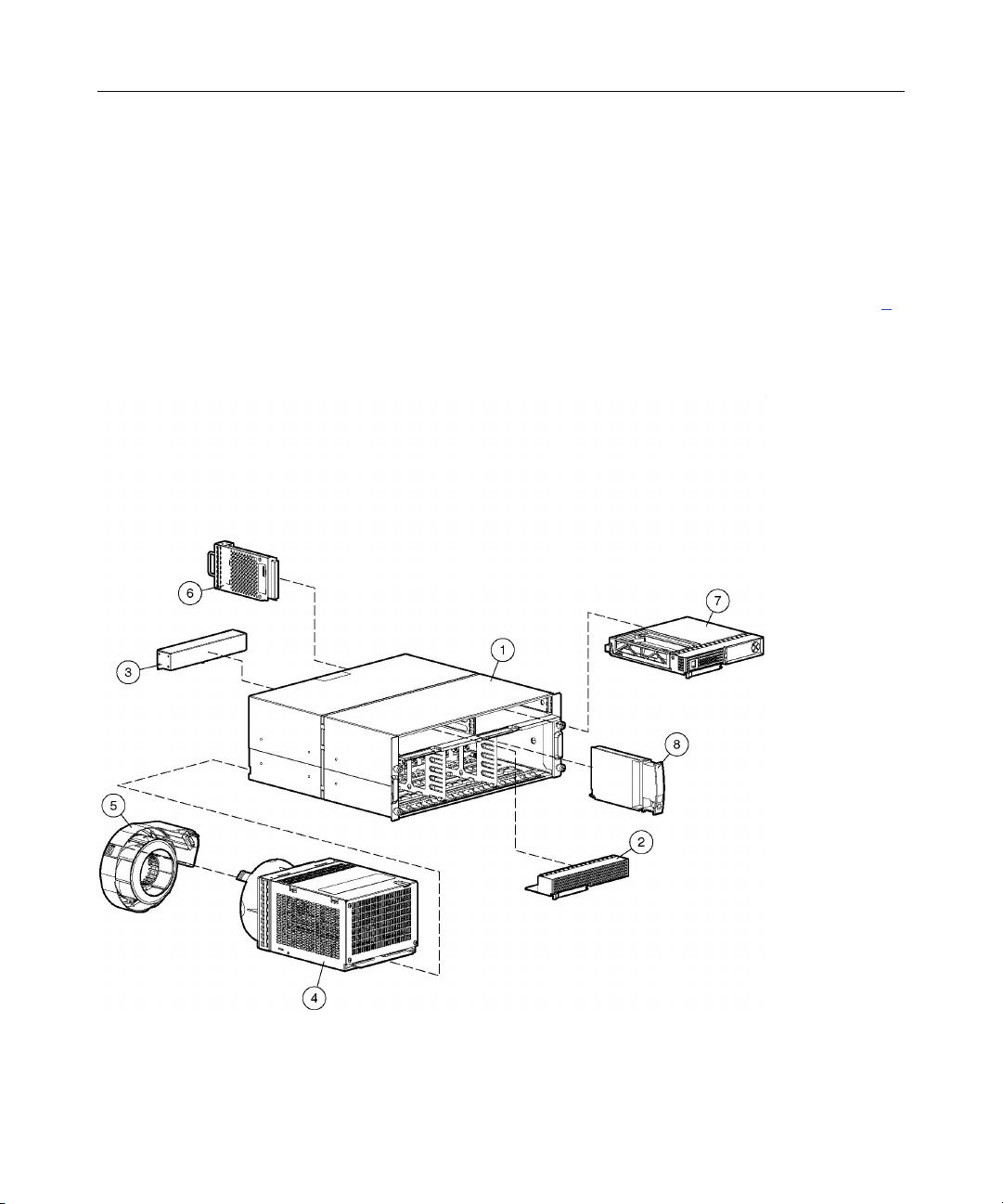
Item Description Spare Part Number
Mechanical Components
1 Chassis, 4U, with backplane 229198-001
2 Bezel blank 229208-001
3 Interconnect blank 229200-001
System Components
4 AC power supply assembly, 499 W 212398-001
5 Blower 123482-001
Boards
6 2-Port Shared Storage Module for MSA500 G2 storage system 343826-001
7 MSA500 G2 controller 343827-001
8 Power button/LED assembly 229201-001
9 Cache module, DIMM, SDRAM, 128 MB, with battery * 171387-001
10 Cache module, DIMM, SDRAM, 256 MB, with battery * 262012-001
Miscellaneous
11 AC power cord * 187335-001
12 Rack mounting hardware kit * 349113-001
13 Return kit * 249670-001
Options
14 4-Port Shared Storage Module for MSA500 G2 storage system * 343825-001
15 Universal hard drive, 1-inch * 177986-001
16 M-Series Rack Rail option * 314635-001
* Not shown
Page 7

7
Removal and Replacement Procedures
In This Section
Safety Considerations.....................................................................................................................7
Power Down the Storage System ...................................................................................................9
Hard Drive Blank .........................................................................................................................10
Hot-Plug SCSI Hard Drive...........................................................................................................11
Bezel Blank ..................................................................................................................................13
Modular Smart Array 500 Generation 2 Controller .....................................................................13
Battery-Backed Cache Module.....................................................................................................15
Blower ..........................................................................................................................................16
Hot-Plug Power Supply................................................................................................................17
2-Port or 4-Port Shared Storage Module ......................................................................................18
Interconnect Blank........................................................................................................................20
Power Button/LED Assembly ......................................................................................................20
Storage System Chassis and Backplane .......................................................................................21
Safety Considerations
Before performing service procedures, review all the safety information.
Preventing Electrostatic Discharge
To prevent damaging the system, be aware of the precautions you need to follow
when setting up the system or handling parts. A discharge of static electricity
from a finger or other conductor may damage system boards or other staticsensitive devices. This type of damage may reduce the life expectancy of the
device.
To prevent electrostatic damage:
• Avoid hand contact by transporting and storing products in static-safe
containers.
• Keep electrostatic-sensitive parts in their containers until they arrive at static-
free workstations.
Page 8
8 HP MSA 500 G2 Storage System Maintenance and Service Guide
• Place parts on a grounded surface before removing them from their
containers.
• Avoid touching pins, leads, or circuitry.
• Always be properly grounded when touching a static-sensitive component or
assembly.
Warnings
Before installing a storage system, be sure that you understand the following
warnings and cautions.
WARNING: To reduce the risk of electric shock or damage
to the equipment:
• Do not disable the power cord grounding plug. The grounding
plug is an important safety feature.
• Plug the power cord into a grounded (earthed) electrical outlet
that is easily accessible at all times.
• Unplug the power cord from the power supply to disconnect
power to the equipment.
• Do not route the power cord where it can be walked on or
pinched by items placed against it. Pay particular attention to
the plug, electrical outlet, and the point where the cord extends
from the storage system.
WARNING: To reduce the risk of personal injury from hot
surfaces, allow the drives and the internal system components to
cool before touching them.
22.7 kg
50 lb
This symbol indicates that the component exceeds the
recommended weight for one individual to handle safely.
Page 9
Removal and Replacement Procedures 9
WARNING: To reduce the risk of personal injury or damage to the
equipment, observe local occupational health and safety
requirements and guidelines for manual material handling.
WARNING: To reduce the risk of personal injury or
damage to the equipment, be sure that:
• The leveling jacks are extended to the floor.
• The full weight of the rack rests on the leveling jacks.
• The stabilizing feet are attached to the rack if it is a single-rack
installation.
• The racks are coupled together in multiple-rack installations.
• Only one component is extended at a time. A rack may become
unstable if more than one component is extended for any
reason.
WARNING: To reduce the risk of personal injury or
equipment damage when unloading a rack:
• At least two people are needed to safely unload the rack from
the pallet. An empty 42U rack can weigh as much as 115 kg
(253 lb), can stand more than 2.1 m (7 ft) tall, and may become
unstable when being moved on its casters.
• Never stand in front of the rack when it is rolling down the ramp
from the pallet. Always handle the rack from both sides.
Power Down the Storage System
WARNING: To reduce the risk of personal injury, electric
shock, or damage to the equipment, remove the power cord to
remove power from the storage system. The front panel Power
On/Standby button does not completely shut off system power.
Portions of the power supply and some internal circuitry remain
active until AC power is removed.
Page 10
10 HP MSA 500 G2 Storage System Maintenance and Service Guide
CAUTION: In systems that use external data storage, be sure
that the server is the first unit to be powered down and the last to be
powered back up. Taking this precaution ensures that the system does
not erroneously mark the drives as failed when the server is powered
up.
IMPORTANT: If installing a hot-plug device, it is not necessary to
power down the storage system.
1. Power down any attached servers. Refer to the server documentation.
2. Press the Power On/Standby button on the storage system. Wait for the
system power LED to go from green to off.
3. Disconnect the power cords.
The system is now without power.
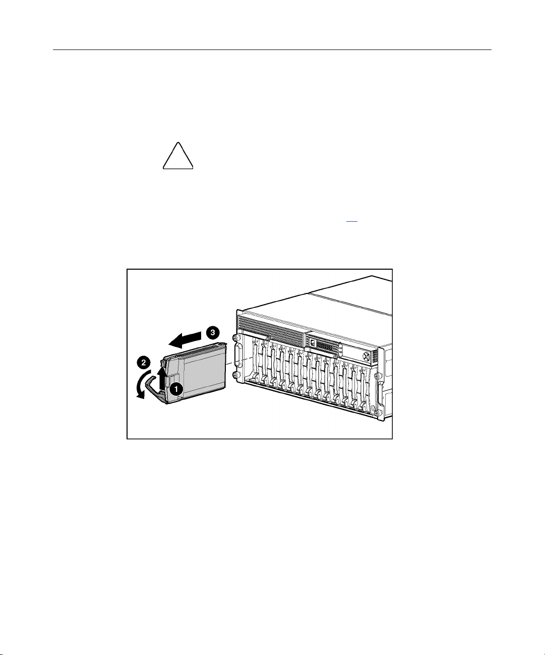
Hard Drive Blank
CAUTION: To prevent improper cooling and thermal damage,
do not operate the storage system unless all bays are populated with
either a component or a blank.
To remove the component:
Page 11

Removal and Replacement Procedures 11
To replace the blank, slide the blank into the bay until it locks into place.
Hot-Plug SCSI Hard Drive
You can replace hard drives without powering down the system. However,
before replacing a degraded drive:
• Open HP SIM and inspect the Error Counter window for each physical drive
in the same array to confirm that no other drives have any errors. (For details,
refer to the HP SIM documentation on the Management CD.)
• Be sure that the array has a current, valid backup.
• Use replacement drives that have a capacity at least as great as that of the
smallest drive in the array. The controller immediately fails drives that have
insufficient capacity.
To minimize the likelihood of fatal system errors, take these precautions when
removing failed drives:
• Do not remove a degraded drive if any other drive in the array is offline (the
Online LED is off). In this situation, no other drive in the array can be
removed without data loss.
Exceptions:
− When RAID 1+0 is used, drives are mirrored in pairs. Several drives can
be in a failed condition simultaneously (and they can all be replaced
simultaneously) without data loss, as long as no two failed drives belong
to the same mirrored pair.
− When RAID ADG is used, two drives can fail simultaneously (and be
replaced simultaneously) without data loss.
− If the offline drive is a spare, the degraded drive can be replaced.
• Do not remove a second drive from an array until the first failed or missing
drive has been replaced and the rebuild process is complete. (The rebuild is
complete when the Online LED on the front of the drive stops blinking.)
These cases are the exceptions:
− In RAID ADG configurations, any two drives in the array can be
replaced simultaneously.
Page 12
12 HP MSA 500 G2 Storage System Maintenance and Service Guide
− In RAID 1+0 configurations, any drives that are not mirrored to other
removed or failed drives can be simultaneously replaced offline without
data loss.
To remove the component:
CAUTION: To prevent improper cooling and thermal damage,
do not operate the storage system unless all bays are populated with
either a component or a blank.
1. Determine the status of the hard drive from the hot-plug hard drive LEDs
("Hot-Plug SCSI Hard Drive LEDs" on page 41
).
2. Back up all data on the hard drive.
3. Remove the hard drive.
To replace the hot-plug SCSI hard drive:
1. Slide the drive into the cage until it clicks, locking the drive into place.
2. Close the lever.
3. Be sure that the drive LEDs illuminate one at a time and then turn off
together to indicate that the system has recognized the new drive.
In fault-tolerant configurations, allow the replacement drive to be
reconstructed automatically with data from the other drives. While
reconstruction is in progress, the online LED flashes.
Page 13
Removal and Replacement Procedures 13
Bezel Blank
To remove the component:
CAUTION: To prevent improper cooling and thermal damage,
do not operate the storage system unless all bays are populated with
either a component or a blank.
To replace the bezel blank:
1. Slide the bezel blank into the bay until it locks into place.
2. Close the lever.
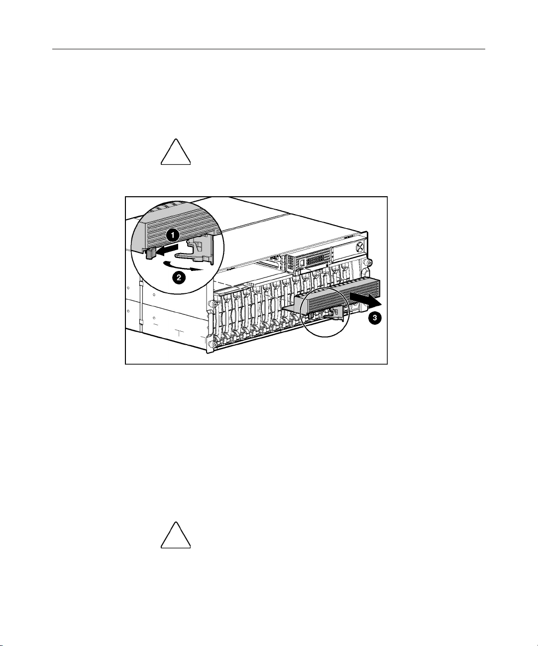
Modular Smart Array 500 Generation 2 Controller
When the controller in a single-controller storage system fails, HP recommends
that you migrate the cache module to a new controller. Battery-backed cache data
in a failed controller can remain intact for up to 3 days with 256-MB modules.
CAUTION: Failure to migrate the cache to a new controller
and flush the data can result in loss of data that is written in the cache
but was unable to be written to the hard drives before controller failure.
Page 14
14 HP MSA 500 G2 Storage System Maintenance and Service Guide
To remove the component:
CAUTION: To prevent improper cooling and thermal damage,
do not operate the storage system unless all bays are populated with
either a component or a blank.
1. Power down the storage system (on page 9).
2. Remove the controller.
To restore the data:
1. Remove the cache modules from the failed controller.
2. Install the cache modules in the new controller.
3. Install the new controller and allow the cache to write the stored data.
To replace the controller:
1. Slide the controller into the bay until it locks into place.
2. Close the lever.
3. Verify that the controller is seated properly by observing the controller
LEDs. When seated properly, the LEDs illuminate when the system is
powered.
Page 15
Removal and Replacement Procedures 15
Battery-Backed Cache Module
To remove the component:
1. Determine if the controller configuration supports hot-plug cache
replacement:
− If the storage system is equipped with a single controller, power down
the storage system (on page 9
− If the system has redundant controllers and the replacement cache is a
different capacity than the failed cache, power down the storage system
(on page 9
− If the system has redundant controllers and the replacement cache is the
same capacity as the failed cache, proceed with step 2.
2. Remove the controller ("Modular Smart Array 500 Generation 2 Controller"
on page 13
3. Remove the existing cache module.
).
).
).
4. Repeat steps 2 and 3 if the storage system has redundant controllers and the
replacement cache is a different capacity than the failed cache.
To replace the cache module:
1. Install the module in the slot.
Page 16
16 HP MSA 500 G2 Storage System Maintenance and Service Guide
2. Close the slot latches.
3. Close the controller.
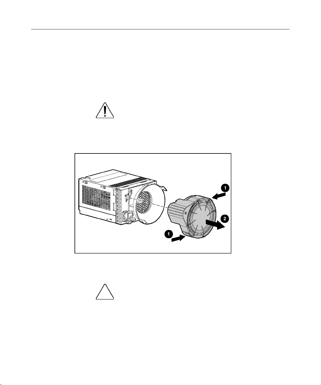
Blower
To remove the component:
WARNING: The blower blades rotate at a high speed.
Avoid touching the rotating blades when removing the blower.
NOTE: The power supply is designed so that removing a blower does
not adversely affect system performance. However, do not remove a
blower until the replacement blower is available.
To replace the blower:
1. Align the guidepost on the blower with the connector on the power supply.
CAUTION: Do not press on the center section of the blower
because this action can damage the blades. Press only on the outer
edge of the blower.
2. Slide the blower into the connector until it locks into place.
3. Be sure the following conditions occur:
Page 17

Removal and Replacement Procedures 17
− The blower begins operating immediately.
− The power supply/blower assembly LED is green.
Hot-Plug Power Supply
Observe the following conditions for AC power supplies:
CAUTION: Removing a power supply significantly changes
the airflow within the chassis. The storage system will shut down to
prevent overheating unless the power supply is replaced within
5 minutes.
CAUTION: Handle the blower carefully to avoid damaging the
housing:
• Do not press on the center section of the blower because this action
can damage the blades. Press only on the outer edge of the blower.
• Do not rest the power supply on the blower because the weight of
the power supply can damage the blower housing.
To remove the component:
1. Disconnect the power cord from the power supply.
2. Remove the blower ("Blower" on page 16
).
Page 18

18 HP MSA 500 G2 Storage System Maintenance and Service Guide
3. Remove the power supply.
To replace the power supply:
1. Lift the locking latch.
2. Slide the power supply into the bay until it locks into place.
3. Install the blower on the power supply.
4. Connect the power cord to the power supply.
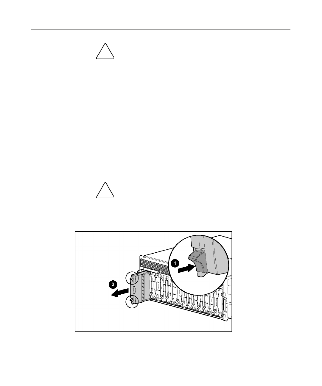
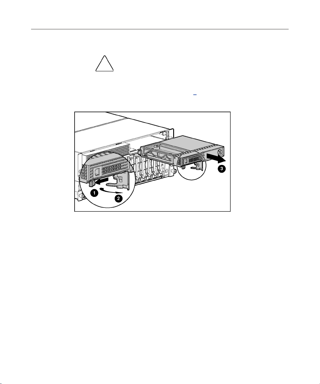
2-Port or 4-Port Shared Storage Module
To remove the component:
1. Power down the storage system (on page 9
2. Disconnect the SCSI cabling connected to the 2-Port Shared Storage Module.
).
Page 19

Removal and Replacement Procedures 19
3. Remove the module.
To replace the component, reverse the removal procedure.
If you are replacing a failed 2-Port Shared Storage Module with a 4-Port Shared
Storage Module, refer to the 4-Port Shared Storage Module Installation
Instructions that ship with the option.
Page 20

20 HP MSA 500 G2 Storage System Maintenance and Service Guide
Interconnect Blank
To remove the component:
CAUTION: To prevent improper cooling and thermal damage,
do not operate the storage system unless all bays are populated with
either a component or a blank.
To replace the component, reverse the removal procedure.
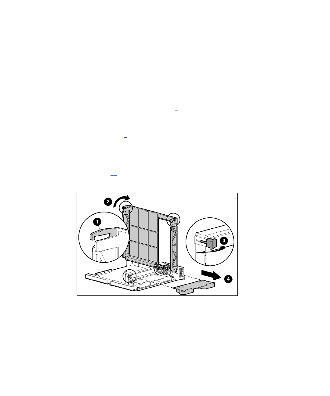
Power Button/LED Assembly
To remove the component:
1. Power down the storage system (on page 9
2. Remove the hot-plug SCSI hard drives in bays 10 through 14 ("SCSI IDs" on
page 40
).
IMPORTANT: To press the plastic latches behind the front bezel, you
may choose to use a flat-head screwdriver.
).
Page 21

Removal and Replacement Procedures 21
3. Remove the power button/LED assembly.
To replace the component, slide the power button/LED assembly into the bay
until it locks into place.
Storage System Chassis and Backplane
If the backplane board fails or the chassis sustains significant damage, you must
order a replacement chassis.
To replace the chassis and backplane:
1. Power down the storage system (on page 9
2. Remove all hard drive blanks ("Hard Drive Blank" on page 10
).
).
3. Remove all hot-plug SCSI hard drives ("Hot-Plug SCSI Hard Drive" on page
).
11
4. Remove the bezel blank ("Bezel Blank" on page 13
).
5. Remove the controllers ("Modular Smart Array 500 Generation 2 Controller"
on page 13
6. Remove all hot-plug power supplies ("Hot-Plug Power Supply" on page 17
).
).
7. Remove the 2-Port or 4-Port Shared Storage Module ("2-Port or 4-Port
Shared Storage Module" on page 18
).
Page 22

22 HP MSA 500 G2 Storage System Maintenance and Service Guide
8. Remove the interconnect blanks ("Interconnect Blank" on page 20).
9. Remove the power button/LED assembly ("Power Button/LED Assembly"
on page 20
).
10. Handwrite the serial number of the original chassis on the label of the
replacement chassis.
IMPORTANT: Always keep the serial number of the original chassis for
warranty validation purposes. After chassis replacement, HP SIM only
recognizes the new serial number.
11. Install all removed components in the new chassis. To replace each
component, refer to the procedures in this section.
Page 23

23
Diagnostic Tools
In This Section
Server Utilities..............................................................................................................................23
ROM Functions and Utilities........................................................................................................24
Array Configuration Utility..........................................................................................................26
Array Diagnostic Utility ...............................................................................................................27
NetWare Online Array Configuration Utility (CPQONLIN).......................................................28
Server Utilities
HP Insight Diagnostics
HP utilities provide reporting functions that enable event-focused management
and diagnostics. To install and run these utilities, refer to the server
documentation.
The HP Insight Diagnostics utility displays information about the server
hardware and tests the system to be sure it is operating properly. The utility has
online help and can be accessed using the SmartStart CD. Online Diagnostics for
Microsoft® Windows® is available for download from the HP website
(http://www.hp.com/support
HP Systems Insight Manager
HP SIM is a web-based application that allows system administrators to
accomplish normal administrative tasks from any remote location, using a web
browser. HP SIM provides device management capabilities that consolidate and
integrate management data from HP and third-party devices.
IMPORTANT: You must install and use HP SIM to benefit from the PreFailure Warranty for processors, hard drives, and memory modules.
For additional information, refer to the Management CD in the HP ProLiant
Essentials Foundation Pack.
).
Page 24

24 HP MSA 500 G2 Storage System Maintenance and Service Guide
Management Agents
Management Agents provide the information to enable fault, performance, and
configuration management. The agents allow easy manageability of the server
through HP Systems Insight Manager software, and third-party SNMP
management platforms. Management Agents are installed with every SmartStart
assisted installation or can be installed through the HP PSP. The System
Management homepage provides status and direct access to in-depth subsystem
information by accessing data reported through the Management Agents. For
additional information, refer to the Management CD in the HP ProLiant
Essentials Foundation Pack or the HP website
(http://www.hp.com/servers/manage).
Survey Utility
Survey Utility, a feature within Insight Diagnostics, gathers critical hardware and
software information on ProLiant servers.
This utility supports operating systems that may not be supported by the server.
For operating systems supported by the server, refer to the HP website
(http://www.hp.com
).
If a significant change occurs between data-gathering intervals, the Survey
Utility marks the previous information and overwrites the Survey text files to
reflect the latest changes in the configuration.
Survey Utility is installed with every SmartStart assisted installation or can be
installed through the HP PSP.
ROM Functions and Utilities
Each MSA500 G2 controller has a ROM that contains the controller firmware.
Page 25

Diagnostic Tools 25
Smart Components for ROM Flash
To update the firmware on the server, controller, or hard drives, use Smart
Components. These components are available on the Firmware Maintenance CD.
A more recent version of a particular component might be available on the
support page of the HP website (http://www.hp.com/support
). Components for
controller and hard drive firmware updates are also available from the software
and drivers page for storage products
(http://www.hp.com/support/proliantstorage).
1. Find the most recent version of the component that you require. Components
for controller firmware updates are available in offline and online formats.
2. Follow the instructions for installing the component on the server. These
instructions are given with the CD and are provided on the same Web page
as the component.
Follow the additional instructions that describe how to use the component to
flash the ROM. These instructions are provided with each component.
Recovery ROM
The Recovery ROM feature stores two complete firmware images in the ROM:
one active image and one backup image. When the controller is powering up, it
checks both firmware images to be sure they are valid. If either image is invalid,
the system overwrites the invalid image with the valid image.
This process, commonly called auto-flashing, is performed automatically by the
controller and does not require any user intervention. The controller display
provides messages for the status of this process.
Controller Firmware Auto Cloning
In a redundant controller configuration, both controllers must execute the same
version of firmware. During power up (or when a redundant controller is
installed as a hot-plug procedure), the storage system compares the controller
firmware versions. If the versions differ, the controller displays a user input
message seeking to initiate Controller Firmware Auto Cloning.
Page 26

26 HP MSA 500 G2 Storage System Maintenance and Service Guide
If 60 seconds elapse with no user input, one of the following actions occurs:
• In a non-hot-plug environment, the controller with the most recent firmware
disables the controller with the older firmware and continues the power-up
sequence. This method prevents automatic loss of a previous version of
firmware.
• In a hot-plug environment, cloning begins automatically, and the storage
system overwrites one firmware version with the other version.
When the cloning is complete, the storage system resets the modified controller.
After the modified controller powers up, the controllers begin operating in
redundant mode.
The storage system clones firmware based on the following criteria:
• Non-Hot-Plug Cloning—If the storage system powers up with both
controllers installed, the storage system clones the most recent firmware
version from either controller.
• Hot-Plug Cloning—If the storage system is operating and an optional
redundant controller is installed, the storage system clones the firmware
version from the primary controller, regardless of which firmware version is
more recent. This cloning method ensures that all host-initiated I/O remains
uninterrupted during storage system operation.
• Incompatible Version Cloning—If a specific version of firmware is
incompatible with certain hardware revisions of a controller, the storage
system displays the user input message seeking to initiate Controller
Firmware Auto Cloning and clones the most recent firmware version that is
compatible with both controllers.
IMPORTANT: During incompatible version cloning, the storage system
does not reset the updated controller if the controller is operating and
processing I/O. In this case, the storage system does not enter
redundant mode and provides an informational message on the
controller display. To configure redundancy, cycle the storage system
power.
Array Configuration Utility
ACU is a browser-based utility with the following features:
Page 27

Diagnostic Tools 27
• Runs as a local application or remote service
• Supports online array capacity expansion, logical drive extension,
assignment of online spares, and RAID or stripe size migration
• Suggests the optimum configuration for an unconfigured system
• Provides different operating modes, enabling faster configuration or greater
control over the configuration options
• Remains available any time that the server is on
• Displays on-screen tips for individual steps of a configuration procedure
The minimum display settings for optimum performance are 800 × 600
resolution and 256 colors. The server must have Microsoft® Internet
Explorer 5.5 (with Service Pack 1) installed and be running Microsoft®
Windows® 2000, Windows® Server 2003, or Linux. Refer to the README.TXT
file for further information about browser and Linux support.
For more information, refer to the HP Array Configuration Utility User Guide on
the Documentation CD or the HP website (http://www.hp.com
).
Array Diagnostic Utility
ADU is a Linux-based tool that collects information about array controllers and
generates a list of detected problems. You can save this data to a file for analysis.
In most cases, ADU provides sufficient information for troubleshooting
procedures.
To obtain ADU, download the utility from the HP website (http://www.hp.com
).
Page 28

28 HP MSA 500 G2 Storage System Maintenance and Service Guide
NetWare Online Array Configuration Utility (CPQONLIN)
The NetWare Online Array Configuration Utility, also called CPQONLIN, is an
NLM for configuring drive arrays without shutting down the storage system.
CPQONLIN also provides information about the status of drives attached to the
MSA500 G2 controller. It indicates drive failure, expansion, or waiting for
expansion or rebuild (queued). Before loading CPQONLIN.NLM, you must load
the appropriate device drivers: CPQRAID.HAM and CPQSHD.CDM.
CPQONLIN.NLM is located in the ProLiant Support Pack found on the
SmartStart CD and it is available on the support software CD that ships with the
storage system.
IMPORTANT: CPQONLIN supports SSP configurations; however, you
can also use ACU 7.10 (or later) offline to enable SSP configurations in
a NetWare environment.
For more information about CPQONLIN, refer to the HP StorageWorks Modular
Smart Array 500 Generation 2 Storage System User Guide or the HP Array
Configuration Utility User Guide on the Documentation CD.
Page 29

29
Component Identification
In This Section
Front Panel Components ..............................................................................................................29
Enclosure LEDs............................................................................................................................30
Rear Panel Components................................................................................................................31
Power Supply/Blower Assembly LEDs........................................................................................32
Shared Storage Module with Integrated Environmental Monitoring Unit ...................................32
Controller Components.................................................................................................................36
SCSI IDs.......................................................................................................................................40
Hot-Plug SCSI Hard Drive LEDs.................................................................................................41
Hot-Plug SCSI Hard Drive LED Combinations...........................................................................42
Front Panel Components
Item Description
1 Bezel blank (bay for optional redundant controller)
2 Service port (for HP service technicians only)
3 Hot-plug HP StorageWorks Modular Smart Array 500
Generation 2 controller
Page 30

30 HP MSA 500 G2 Storage System Maintenance and Service Guide
Item Description
4 Controller display
5 Power On/Standby button
6 Enclosure LEDs
7 Hot-plug SCSI hard drive bays with blanks
Enclosure LEDs
Item Description Status
1 EMU heartbeat Green flashing = Shared storage module is operating normally.
Green/Off = Shared storage module is not operating normally.
2 System power Green = System power is On.
Off = System is in standby mode or power is removed from the
system.
3 Fault Amber = Fault is detected in a subsystem.
Off = No faults are detected.
Page 31

Component Identification 31
Rear Panel Components
Item Description
1 Interconnect blanks (required for proper airflow)
2 Power supply/blower assemblies
3 AC power connectors
4 2-Port Shared Storage Module
Page 32

32 HP MSA 500 G2 Storage System Maintenance and Service Guide
Power Supply/Blower Assembly LEDs
The power supply/blower assembly LEDs have two functions:
• Green—The power supply is receiving power, and the blower is operating
normally.
• Off—No power is present; the power supply or the blower has failed.
Shared Storage Module with Integrated Environmental Monitoring Unit
The storage system supports multipath two-node clustering and up to four-node
shared storage with Ultra320 SCSI I/O hardware. The storage system ships
standard with the 2-Port Shared Storage Module. A 4-Port Shared Storage
Module is available as an option.
Functions include:
• Provides the interconnect function to the server nodes
• Monitors the enclosure operation for:
− Temperature
− Power supplies
Page 33

Component Identification 33
− Blowers
− Drive presence
• Detects and reports component changes in the enclosure (identifies hot-plug
addition and removal)
• Controls drive and enclosure LEDs
2-Port Shared Storage Module Components
Item Description Bus
1 SCSI port connector A
2 SCSI port connector B
Page 34

34 HP MSA 500 G2 Storage System Maintenance and Service Guide
2-Port Shared Storage Module LEDs
Item LED Description Status
1 Power Flashing green = Power on
Off = Power off
2 SCSI host port A Flashing green = On/Activity
Off = Off
3 SCSI host port B Flashing green = On/Activity
Off = Off
Page 35

Component Identification 35
4-Port Shared Storage Module Components
Item Description Bus
1 SCSI port connector A1 A
2 SCSI port connector A2 A
3 SCSI port connector B1 B
4 SCSI port connector B2 B
Page 36

36 HP MSA 500 G2 Storage System Maintenance and Service Guide
4-Port Shared Storage Module LEDs
Item LED Description Status
1 Power Flashing green = Power on
2 SCSI host port A
connectors 1 and 2
3 SCSI host port B
connectors 1 and 2
Controller Components
Controller Display (on page 37)
Controller LEDs (on page 38
Battery-Backed Write Cache Enabler Overview (on page 39
Off = Power off
Flashing green = On/Activity
Off = Off
Flashing green = On/Activity
Off = Off
)
)
Page 37

Component Identification 37
Controller Display
Each controller LCD provides informational and error messages.
Item Description
1 Display
2 Left button
3 Up button
4 Right button
5 Down button
Page 38

38 HP MSA 500 G2 Storage System Maintenance and Service Guide
Controller LEDs
Item LED Description Status
0-2 Busy status Green = Controller is idle.
Off = Controller is operating at full capacity.
3-5 No function —
6 Host port A notification Green = Notify On Event command is
active.
Off = No Notify On Event command is
active.
7 Host port B notification Green = Notify On Event command is
active.
Off = No Notify On Event command is
active.
8 Idle heartbeat Controller is idle and functioning.
9 Active/Standby Green = Controller is active.
Off = Controller is in standby.
10 DMA activity Green = DMA transfers are active.
Off = No DMA transfers are active.
Page 39

Component Identification 39
Item LED Description Status
11 Logical I/O activity Green = System is currently processing
logical requests from the host adapter.
Off = System is not processing any logical
requests.
12 SCSI bus 0 activity Green = Outstanding requests exist on the
SCSI bus.
Off = No outstanding requests exist.
13 SCSI bus 1 activity Green = Outstanding requests exist on the
SCSI bus.
Off = No outstanding requests exist.
14 Cache activity Green = Cache activity is present.
Off = No cache activity is present.
Flashing green = Cache transfer is
pending.
15 Drive failure Green = An array-configured drive has
failed.
Off = No drives have failed.
16 Active redundancy Green = Controllers are operating with
redundancy.
Off = No redundancy exists.
17 Fault Amber = Error message has been received
by the controller display.
Off = No error message has been received
or no error message is displayed currently.
Battery-Backed Write Cache Enabler Overview
The Battery-Backed Write Cache Enabler, also known as the battery module,
provides transportable data protection, increases overall controller performance,
and maintains any cached data for up to 72 hours. The NiMH batteries in the
battery module are continuously recharged through a trickle-charging process
whenever the system power is on. Under normal operating conditions, the battery
module lasts for 3 years before replacement is necessary.
Page 40

40 HP MSA 500 G2 Storage System Maintenance and Service Guide
NOTE: The data protection and the time limit also apply if a power
outage occurs. When power is restored to the system, an initialization
process writes the preserved data to the hard drives.
To enable faster data access from disk storage, the battery module performs two
types of caching:
• Posted-write caching—the controller writes user data in the cache memory
on the module rather than directly to the drives. Later, when the storage
system is idle, the controller writes the data to the drive array.
• Read-ahead caching—the controller detects sequential array access, reads
ahead into the next sequence of data, and stores the data in the read-ahead
cache. Then, if the next read access is for the cached data, the controller
immediately loads the data into system memory, avoiding the latency of a
disk access.
SCSI IDs
Bay SCSI ID Bus Port
1 0 0
2 1 0
3 2 0
4 3 0
Page 41

Component Identification 41
Bay SCSI ID Bus Port
5 4 0
6 5 0
7 8 0
8 0 1
9 1 1
10 2 1
11 3 1
12 4 1
13 5 1
14 8 1
Hot-Plug SCSI Hard Drive LEDs
Item LED Description Status
1 Activity status On = Drive activity
Flashing = High activity on the drive or drive
is being configured as part of an array.
Off = No drive activity
Page 42

42 HP MSA 500 G2 Storage System Maintenance and Service Guide
Item LED Description Status
2 Online status On = Drive is part of an array and is
currently working.
Flashing = Drive is actively online.
Off = Drive is offline.
3 Fault status On = Drive failure
Flashing = Fault-process activity
Off = No fault-process activity
Hot-Plug SCSI Hard Drive LED Combinations
Activity
LED (1)
Online
LED (2)
Fault LED
(3)
Interpretation
On, off, or
flashing
On, off, or
flashing
On or
flashing
On Off Off
Flashing Flashing Flashing
Off Off On The drive has failed and has been placed offline.
On or off Flashing A predictive failure alert has been received for this drive.
Replace the drive as soon as possible.
On Off The drive is online and is configured as part of an array.
If the array is configured for fault tolerance and all other drives in the
array are online, and a predictive failure alert is received or a drive
capacity upgrade is in progress, you may replace the drive online.
Flashing Off
Do not remove the drive. Removing a drive may terminate the
current operation and cause data loss.
The drive is rebuilding or undergoing capacity expansion.
Do not remove the drive.
The drive is being accessed, but (1) it is not configured as part of an
array; (2) it is a replacement drive and rebuild has not yet started; or
(3) it is spinning up during the POST sequence.
Do not remove the drive. Removing a drive may cause data loss
in non-fault-tolerant configurations.
Either (1) the drive is part of an array being selected by an array
configuration utility; (2) Drive Identification has been selected in
HP SIM; or (3) drive firmware is being updated.
You may replace the drive.
Page 43

Component Identification 43
Activity
LED (1)
Online
LED (2)
Fault LED
(3)
Interpretation
Off Off Off Either (1) the drive is not configured as part of an array; (2) the drive
is configured as part of an array, but it is a replacement drive that is
not being accessed or being rebuilt yet; or (3) the drive is configured
as an online spare.
If the drive is connected to an array controller, you may replace the
drive online.
Page 44

Page 45

45
Specifications
In This Section
Environmental Specifications.......................................................................................................45
Dimensions and Weight................................................................................................................45
Power Specifications ....................................................................................................................46
Environmental Specifications
Temperature range
Operating
Shipping
Maximum wet bulb
temperature
NOTE: All temperature ratings shown are for sea level. An altitude
derating of 1°C per 300 m (1.8°F per 1,000 ft) to 3048 m (10,000 ft)
is applicable. No direct sunlight allowed.
Relative humidity (noncondensing)
Operating 10% to 90%
Non-operating 5% to 95%
NOTE: Storage maximum humidity of 95% is based on a
maximum temperature of 45°C (113°F). Altitude maximum for
storage corresponds to a pressure minimum of 70 KPa.
Dimensions and Weight
Parameter Value
Height 17.5 cm (6.9 in)
Depth 52.1 cm (20.5 in)
10°C to 35°C (50°F to 95°F)
-40°C to 70°C (-40°F to 158°F)
28°C (82.4°F)
Width 48.3 cm (19.0 in)
Page 46

46 HP MSA 500 G2 Storage System Maintenance and Service Guide
Parameter Value
Weight (no drives installed) 22.7 kg (50 lb)
Power Specifications
Parameter Value
Rated input voltage 100 VAC to 240 VAC
Rated input frequency 50 Hz to 60 Hz
Rated input current 7.35 A Max
Rated input power 641 W *
BTUs per hour 2187 *
Rated steady-state power 377 W
Maximum peak power 681 W
Acoustic noise (LWAdc bels
and LpAm dBA)
Idle <6.9 and 53
Fixed disk (random writes) <7.3 and 54
* Input power and heat dissipation specifications are maximum
values and apply to worst-case conditions at a full-rated power
supply load. The power/heat dissipation for each installation
varies depending on the equipment configuration.
Page 47

47
Acronyms and Abbreviations
ACU
Array Configuration Utility
ADG
Advanced Data Guarding
ADU
Array Diagnostics Utility
ASIC
application specific integrated circuit
ASR
Automatic Server Recovery
CPQONLIN
NetWare Online Array Configuration Utility
DDR
double data rate
DMA
direct memory access
Page 48

48 HP MSA 500 G2 Storage System Maintenance and Service Guide
ECC
error checking and correcting
EMU
environmental monitoring unit
HBA
host bus adapter
I2C
inter-integrated circuit
IEC
International Electrotechnical Commission
KVM
keyboard, video, and mouse
LCD
liquid crystal display
LED
light-emitting diode
LVD
low-voltage differential
NEMA
National Electrical Manufacturers Association
Page 49

Acronyms and Abbreviations 49
NFPA
National Fire Protection Association
NIC
network interface controller
NLM
NetWare Loadable Module
NVRAM
non-volatile memory
ORCA
Option ROM Configuration for Arrays
PDU
power distribution unit
POST
Power-On Self-Test
RIS
reserve information sector
ROM
read-only memory
SA
Smart Array
Page 50

50 HP MSA 500 G2 Storage System Maintenance and Service Guide
SE
single-ended
SIM
Systems Insight Manager
SMART
self-monitoring analysis and reporting technology
SSP
selective storage presentation
TMRA
recommended ambient operating temperature
UPS
uninterruptible power system
VHDCI
very high density cable interconnect
Page 51

51
drive failure LED 38
Index
drive LEDs 38, 41
E
2
2-Port Shared Storage Module 18, 33, 34
4
4-Port Shared Storage Module 18, 35, 36
A
active redundancy LED 38
active/standby LED 38
ACU (Array Configuration Utility) 26
ADU (Array Diagnostics Utility) 27
Array Configuration Utility (ACU) 26
B
Battery-Backed Write Cache Enabler 15, 39
bezel, removing 13
blanks 31
blower assembly 31, 32
busy status LED 38
buttons 29, 37
C
cache activity LED 38
component identification 29
configuration utilities 23
connectors 31, 33, 35
controller display, LCD 29, 37
controller LEDs 38
D
diagnostic tools 23
DMA activity LED 38
drive bays 29, 40
electrostatic discharge 7
EMU heartbeat LED 30
enclosure LEDs 30
environmental requirements 45
environmental specifications 45
F
fans 31
fault LED 38
firmware upgrades 24
front panel components 29
front panel LEDs 30
H
hard drive blanks 10
hard drive LEDs 41, 42
hard drive, replacing 11
hard drives 11, 41, 42
host port notification LED 38
hot-plug power supply 17
HP Insight Diagnostics 23
HP ProLiant Essentials Foundation Pack 23
I
idle heartbeat LED 38
illustrated parts catalog 5
Insight Diagnostics 23
L
LCD 37
LED, power button 30
LEDs, controller 38
LEDs, hard drive 41
logical I/O activity LED 38
Page 52

52 HP MSA 500 G2 Storage System Maintenance and Service Guide
M
Management Agents 24
management tools 23
O
Online ROM Flash Component Utility 25
P
part numbers 5
physical specifications 45
power button/LED board 20
power connectors, external 31
Power On/Standby button 9, 29
power supplies 17
power supply LEDs 32
power supply output 46
powering down 9
R
RAID configuration 26
rear panel LEDs 32
removal and replacement procedures 7
ROM, updating 24, 25
T
temperature requirements 45
tools 23
U
updating 24
utilities 23, 24, 25, 26, 27
S
safety considerations 7
SCSI bus activity LED 38
SCSI IDs 40
serial number 21
Shared Storage Module 18, 32
spare part numbers 5
specifications 45
specifications, server 45
static electricity 7
Survey Utility 24
system power LED 30
Systems Insight Manager 23
 Loading...