

Page 1

HP BladeSystem p-Class Enclosure
Installation Guide
March 2005 (Second Edition)
Part Number 354556-002
Page 2

© Copyright 2005 Hewlett-Packard Development Company, L.P.
The information contained herein is subject to change without notice. The only warranties for HP products
and services are set forth in the express warranty statements accompanying such products and services.
Nothing herein should be construed as constituting an additional warranty. HP shall not be liable for
technical or editorial errors or omissions contained herein.
March 2005 (Second Edition)
Part Number 354556-002
Page 3

3
Contents
Planning the installation 7
Rack requirements................................................................................................................................7
Warnings, cautions, and importants..................................................................................................... 8
Space and airflow requirements......................................................................................................... 11
Temperature requirements ................................................................................................................. 12
Power requirements............................................................................................................................12
Grounding requirements ....................................................................................................................13
Installing HP BladeSystem p-Class enclosures 15
Installation overview.......................................................................................................................... 15
Measuring with the rack template...................................................................................................... 16
Installing the rack rails and cage nuts ................................................................................................ 16
Installing the HP BladeSystem p-Class 1U Power Enclosure rack rails................................. 17
Installing the rack rails (3U power supply and server blade enclosures)................................17
Installing the cage nuts ...........................................................................................................20
Installing HP BladeSystem p-Class enclosures into the rack............................................................. 20
Installing HP BladeSystem p-Class 1U Power Enclosures.....................................................21
Identifying HP BladeSystem p-Class 1U Power Supply Enclosure bays............................... 21
Installing an HP BladeSystem 1U Power Supply................................................................... 22
Installing HP BladeSystem p-Class 3U Power Enclosures.....................................................23
Identifying HP BladeSystem p-Class 3U Power Enclosure bays ...........................................23
Installing an HP BladeSystem 3U Power Supply................................................................... 24
Installing HP BladeSystem p-Class Server Blade Enclosures................................................ 25
Installing interconnects ......................................................................................................................25
Installing HP BladeSystem interconnect modules and RJ-45 patch panels............................26
Installing HP BladeSystem interconnect modules and interconnect switches........................27
Cabling and powering up the system 29
System cabling overview ...................................................................................................................29
Identifying HP BladeSystem p-Class 1U Power Enclosure components...........................................31
Identifying HP BladeSystem p-Class 3U Power Enclosure and Server Blade Enclosure components32
Installing power distribution devices ................................................................................................. 33
Installing a scalable bus bar kit...............................................................................................35
Installing a mini bus bar kit ....................................................................................................36
Installing a power bus box......................................................................................................36
Installing the power connectors.............................................................................................. 38
Cabling the management modules .....................................................................................................39
Page 4

4 HP BladeSystem p-Class Enclosure Installation Guide
Management cabling guidelines ............................................................................................. 39
Additional guidelines for a 42U solution................................................................................ 40
Connecting the management module cables........................................................................... 40
Connecting the HP BladeSystem p-Class 1U Management Link Cable.................................42
Connecting to iLO ..................................................................................................................43
Cabling the network to the system..................................................................................................... 43
Connecting the HP BladeSystem p-Class 1U DC power cable to the server blade enclosure ...........44
Connecting power cables to a mini bus bar........................................................................................44
Removing the mini bus bar cover...........................................................................................45
Connecting power cables to the mini bus bar......................................................................... 45
Replacing the mini bus bar cover ...........................................................................................46
Securing the mini bus bars......................................................................................................47
Connecting power cables to a scalable bus bar..................................................................................47
Removing the scalable bus bar covers.................................................................................... 48
Connecting power cables to the scalable bus bar....................................................................48
Replacing the scalable bus bar cover...................................................................................... 49
Securing the scalable bus bars................................................................................................50
Connecting the load-balancing signal cable ...........................................................................50
Connecting facility DC power to the power distribution bus bars .....................................................51
Installing the cable bracket ................................................................................................................52
Configuration examples .....................................................................................................................52
Scalable bus bar configuration example .................................................................................53
Two mini bus bar configuration example...............................................................................54
Redundant mini bus bar configuration example .....................................................................55
Full rack 42U solution with two pairs of mini bus bars.......................................................... 56
Configuring the Dynamic Power Saver.................................................................................. 57
Powering up the system .....................................................................................................................59
Powering up the system (HP BladeSystem p-Class 1U Power Enclosure).............................59
Powering up the system (HP BladeSystem p-Class 3U Power Enclosure).............................60
Powering up the system (facility DC).....................................................................................61
Completing the installation ................................................................................................................62
LEDs, buttons, and switches 63
LEDs ..................................................................................................................................................63
Server blade enclosure LEDs..................................................................................................63
Server blade management module LEDs................................................................................64
Power management module LEDs ......................................................................................... 65
HP BladeSystem p-Class 1U Power Enclosure LEDs............................................................ 67
HP BladeSystem p-Class 3U Power Enclosure LEDs............................................................ 69
HP BladeSystem p-Class 1U Power Supply LEDs.................................................................70
HP BladeSystem p-Class 3U Power Supply LEDs.................................................................71
Buttons and switches..........................................................................................................................71
Reset and UID buttons............................................................................................................72
Power configuration switches................................................................................................. 72
Page 5

Contents 5
Troubleshooting 77
Troubleshooting resources .................................................................................................................77
Important safety information..............................................................................................................77
Symbols on equipment ...........................................................................................................78
Warnings and cautions............................................................................................................79
Regulatory compliance notices 83
Regulatory compliance identification numbers..................................................................................83
Federal Communications Commission notice....................................................................................84
FCC rating label......................................................................................................................84
Class A equipment.................................................................................................................. 84
Class B equipment.................................................................................................................. 85
Declaration of conformity for products marked with the FCC logo, United States only...................85
Modifications .....................................................................................................................................86
Cables.................................................................................................................................................86
Canadian notice (Avis Canadien).......................................................................................................86
European Union regulatory notice .....................................................................................................87
Japanese notice...................................................................................................................................88
Power cord statement for Japan ......................................................................................................... 88
BSMI notice....................................................................................................................................... 88
Korean notice A&B ...........................................................................................................................89
Laser compliance ...............................................................................................................................89
Battery replacement notice.................................................................................................................90
Taiwan battery recycling notice......................................................................................................... 91
Electrostatic discharge 93
Preventing electrostatic discharge...................................................................................................... 93
Grounding methods to prevent electrostatic discharge ......................................................................94
Technical support 95
Before you contact HP....................................................................................................................... 95
HP contact information...................................................................................................................... 95
Acronyms and abbreviations 97
Index 103
Page 6

Page 7

7
Planning the installation
In this section
Rack requirements ..........................................................................................................................7
Warnings, cautions, and importants................................................................................................8
Space and airflow requirements ...................................................................................................11
Temperature requirements............................................................................................................12
Power requirements ......................................................................................................................12
Grounding requirements...............................................................................................................13
Rack requirements
The HP BladeSystem p-Class Server Blade Enclosure is compatible with the
following racks:
•
41U, 33U, and 25U HP Rack System/E
•
42U, 36U, and 22U Compaq branded 10000 and 9000 Series racks
NOTE: The system is optimized for 10000 Series racks.
•
Telco racks
•
Third-party rack cabinets that meet the following requirements:
– Width - 48.26 cm (19 in)
– Depth - 73.66 cm (29 in) between front and rear RETMA rails
– Clearance - 7.62 cm (3 in) minimum clearance between rear RETMA
rails and rear rack door to accommodate system cabling
– Open area - minimum of 65 percent open area to provide adequate airflow
through any rack front or rear doors
Page 8

8 HP BladeSystem p-Class Enclosure Installation Guide
Warnings, cautions, and importants
WARNING: To reduce the risk of personal injury or
damage to equipment, heed all warnings and cautions throughout
the installation instructions.
WARNING: To reduce the risk of personal injury or
damage to the equipment, be sure that:
The leveling jacks are extended to the floor. •
•
The full weight of the rack rests on the leveling jacks.
•
The stabilizing feet are attached to the rack if it is a single-rack
installation.
•
The racks are coupled together in multiple-rack installations.
•
Only one component is extended at a time. A rack may become
unstable if more than one component is extended for any
reason.
WARNING: To reduce the risk of personal injury or
equipment damage when unloading a rack:
At least two people are needed to safely unload the rack from
•
the pallet. An empty 42U rack can weigh as much as 115 kg
(253 lb), can stand more than 2.1 m (7 ft) tall, and may become
unstable when being moved on its casters.
• Never stand in front of the rack when it is rolling down the ramp
from the pallet. Always handle the rack from both sides.
WARNING: To reduce the risk of personal injury or
equipment damage, be sure that the rack is adequately stabilized
before extending a component from the rack.
Page 9
Planning the installation 9
WARNING: The power enclosure and the server blade
enclosure are very heavy. To reduce the risk of personal injury or
damage to the equipment:
Observe local occupational health and safety requirements and
•
guidelines for manual material handling.
• • Remove hot-plug power supplies and server blades from their
enclosures before installing or removing the enclosures.
Use caution and get help to lift and stabilize enclosures during
installation or removal, especially when the enclosure is not
fastened to the rack.
WARNING: To reduce the risk of personal injury or
damage to the equipment, you must adequately support
enclosures during installation and removal.
WARNING: Always use at least two people to lift an
enclosure into the rack. If the enclosure is being loaded into the
rack above chest level, a third person must assist with aligning the
enclosure with the rails while the other two people support the
weight of the enclosure.
WARNING: Before installing an enclosure in the rack, be
sure that all hot-plug power supplies, server blades, and
interconnects are removed from the enclosure. Blanks can be left
in the enclosure.
WARNING: Be sure to install enclosures starting from the
bottom of the rack and work your way up the rack.
These symbols, on power supplies or systems,
indicate that the equipment is supplied by multiple sources of
power.
WARNING: To reduce the risk of injury from electric shock,
remove all power cords to completely disconnect power from the
system.
Page 10

10 HP BladeSystem p-Class Enclosure Installation Guide
Each power enclosure has two or more power supply cords. A
•
single rack or cabinet may contain more than one power
enclosure. Power may be supplied in a redundant fashion.
Removing any single source of power does not necessarily
remove power from any portion of the system. When
performing any service other than hot-plug module
replacement, you must completely disconnect all power to that
portion of the system.
• • When performing service procedures on server blade
enclosures, ensure that both A and B DC power feeds are
disconnected from the enclosure before servicing.
When performing service procedures on power enclosures,
shut off the circuit breakers to both A and B AC power feeds
and then disconnect both power cords from the wall outlet
before servicing.
WARNING: To reduce the risk of personal injury from hot
surfaces, allow the drives and the internal system components to
cool before touching them.
WARNING: To reduce the risk of electric shock or damage
to the equipment, enter enclosures or perform service on system
components only as instructed in the user documentation.
WARNING: A risk of electric shock from high leakage
current exists. Before connecting the AC supply to the power
enclosures, be sure that the electrical outlets are properly
grounded (earthed).
CAUTION: Always be sure that equipment is properly
grounded and that you follow proper grounding procedures before
beginning any installation procedure. Improper grounding can result in
ESD damage to electronic components. For more information, refer to,
"Electrostatic Discharge (on page 93
CAUTION: When performing non-hot-plug operations, you
must power down the server blade and/or the system. Use caution
when performing other operations, such as hot-plug installations or
troubleshooting.
)."
Page 11

Planning the installation 11
CAUTION: Protect the equipment from AC power fluctuations
and temporary interruptions with a regulating facility UPS device. This
device protects the hardware from damage caused by power surges
and voltage spikes and keeps the system in operation during a power
failure.
IMPORTANT: Data on the dimensions and weights of HP BladeSystem
p-Class components can be found in the HP BladeSystem p-Class
System Maintenance and Service Guide. The same data can be
determined by using the online HP BladeSystem p-Class Sizing Utility.
Space and airflow requirements
To enable servicing and ensure adequate airflow, observe the following spatial
requirements when deciding where to install an HP branded, Compaq branded,
telco, or third-party rack:
•
Leave a minimum clearance of 63.5 cm (25 in) in front of the rack.
•
Leave a minimum clearance of 76.2 cm (30 in) in back of the rack.
•
Leave a minimum clearance of 121.9 cm (48 in) from the back of the rack to
the rear of another rack or row of racks.
HP BladeSystem servers draw cool air in through the front and expel warm air
through the rear of the enclosure. Therefore, the front of the rack enclosure must
be adequately ventilated to enable ambient room air to enter the enclosure, and
the rear of the enclosure must be adequately ventilated to enable the warm air to
escape from the enclosure.
IMPORTANT: Do not block the ventilation openings.
If the front of the rack is not completely filled with components, the remaining
gaps between the components can cause changes in the airflow, which can
adversely affect cooling within the rack. Cover these gaps with blanking panels.
CAUTION: Always use blanking panels to fill empty vertical
spaces in the rack. This arrangement ensures proper airflow. Using a
rack without blanking panels results in improper cooling that can lead to
thermal damage.
Page 12

12 HP BladeSystem p-Class Enclosure Installation Guide
Compaq branded 9000 Series racks provide proper server cooling from flowthrough perforations in the front and rear doors that provide 65 percent open area
for ventilation.
CAUTION: Always use blanks to fill empty spaces in
enclosures. This arrangement ensures proper airflow. Using an
enclosure without the proper blanks results in improper cooling that can
lead to thermal damage.
Temperature requirements
To ensure continued safe and reliable equipment operation, install or position the
rack in a well ventilated, climate-controlled environment.
The operating temperature inside the rack is always higher than the room
temperature and is dependent on the configuration of equipment in the rack.
Check the TMRA for each piece of equipment before installation.
CAUTION: To reduce the risk of damage to the equipment
when installing third-party options:
• • Do not permit optional equipment to impede airflow around the
equipment or to increase the internal rack temperature beyond the
maximum allowable limits.
Do not exceed the manufacturer’s TMRA.
Power requirements
WARNING: A risk of fire or damage to the equipment
exists.
Each AC power cord for the power enclosure has an electrical
rating based on the model and power supply configuration. The
rating is marked on the side of the enclosure.
Page 13

Planning the installation 13
It is important that the system be configured according to the
guidelines in the HP BladeSystem p-Class System Overview and
Planning white paper. Failure to follow these guidelines may result
in an overload of the electrical circuits feeding the power
enclosure.
When performing system upgrades, refer to the HP BladeSystem
p-Class System Overview and Planning white paper to be sure that
the new configuration does not overload the existing power
enclosure scheme.
Installation of this equipment must comply with local and regional electrical
regulations governing the installation of IT equipment by licensed electricians.
This equipment is designed to operate in installations covered by NFPA 70, 1999
Edition (National Electric Code) and NFPA-75, 1992 (code for Protection of
Electronic Computer/Data Processing Equipment). For electrical power ratings
on options, refer to the product rating label or the user documentation supplied
with that option.
WARNING: To reduce the risk of personal injury, fire, or
damage to the equipment, do not overload the AC supply branch
circuit that provides power to the rack. Consult the electrical
authority having jurisdiction over wiring and installation
requirements of your facility.
CAUTION: Protect the equipment from power fluctuations and
temporary interruptions with a regulating UPS. This device protects the
hardware from damage caused by power surges and voltage spikes and
keeps the equipment in operation during a power failure.
Grounding requirements
This equipment must be grounded properly for proper operation and safety. In
the United States, you must install the equipment in accordance with
NFPA 70, 1999 Edition (National Electric Code), Article 250, as well as any
local and regional building codes.
In Canada, you must install the equipment in accordance with Canadian
Standards Association, CSA C22.1, Canadian Electrical Code.
Page 14

14 HP BladeSystem p-Class Enclosure Installation Guide
In all other countries, you must install the equipment in accordance with any
regional or national electrical wiring codes, such as the International
Electrotechnical Commission (IEC) Code 364, parts 1 through 7. Furthermore,
you must be sure that all power distribution devices used in the installation, such
as branch wiring and receptacles, are listed or certified grounding-type devices.
Because of the high ground-leakage currents associated with this equipment, HP
recommends the use of a PDU that is either permanently wired to the building’s
branch circuit or includes a nondetachable cord that is wired to an industrial-style
plug. NEMA locking-style plugs or those complying with IEC 60309 are
considered suitable for this purpose. Using common power outlet strips to supply
power to this equipment is not recommended.
Page 15

15
Installing HP BladeSystem p-Class enclosures
In this section
Installation overview ....................................................................................................................15
Measuring with the rack template ................................................................................................16
Installing the rack rails and cage nuts...........................................................................................16
Installing HP BladeSystem p-Class enclosures into the rack .......................................................20
Installing interconnects.................................................................................................................25
Installation overview
To install an enclosure into the rack:
1. If you are installing the HP BladeSystem 3U power enclosure, use the rack
template ("Measuring with the rack template" on page 16
) to mark the
locations for power distribution devices.
2. Install the rack rails ("Installing the rack rails (3U power supply and server
blade enclosures)" on page 17
3. Install the cage nuts ("Installing the cage nuts" on page 20
IMPORTANT: You must install cage nuts for each power distribution
device (scalable bus bar or mini bus bar).
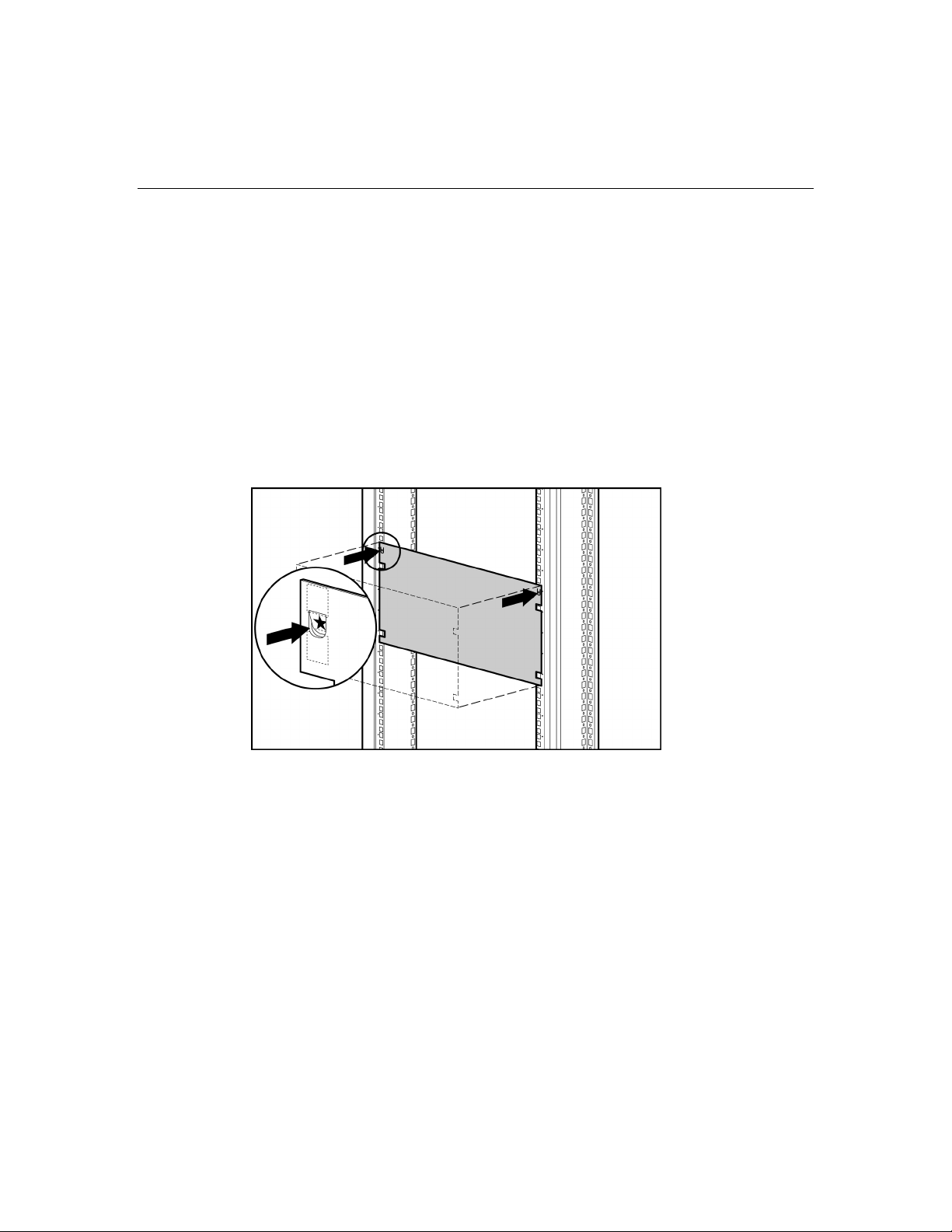
IMPORTANT: Be sure that the guiding fins on the enclosure seat
properly in the guiding groove on the rack rail.
) for each enclosure.
), if necessary.
4. Position yourself at the front of the rack, and align the enclosure guiding fins
with the guiding groove in the rack rails.
5. Slide the enclosure fully into the rack.
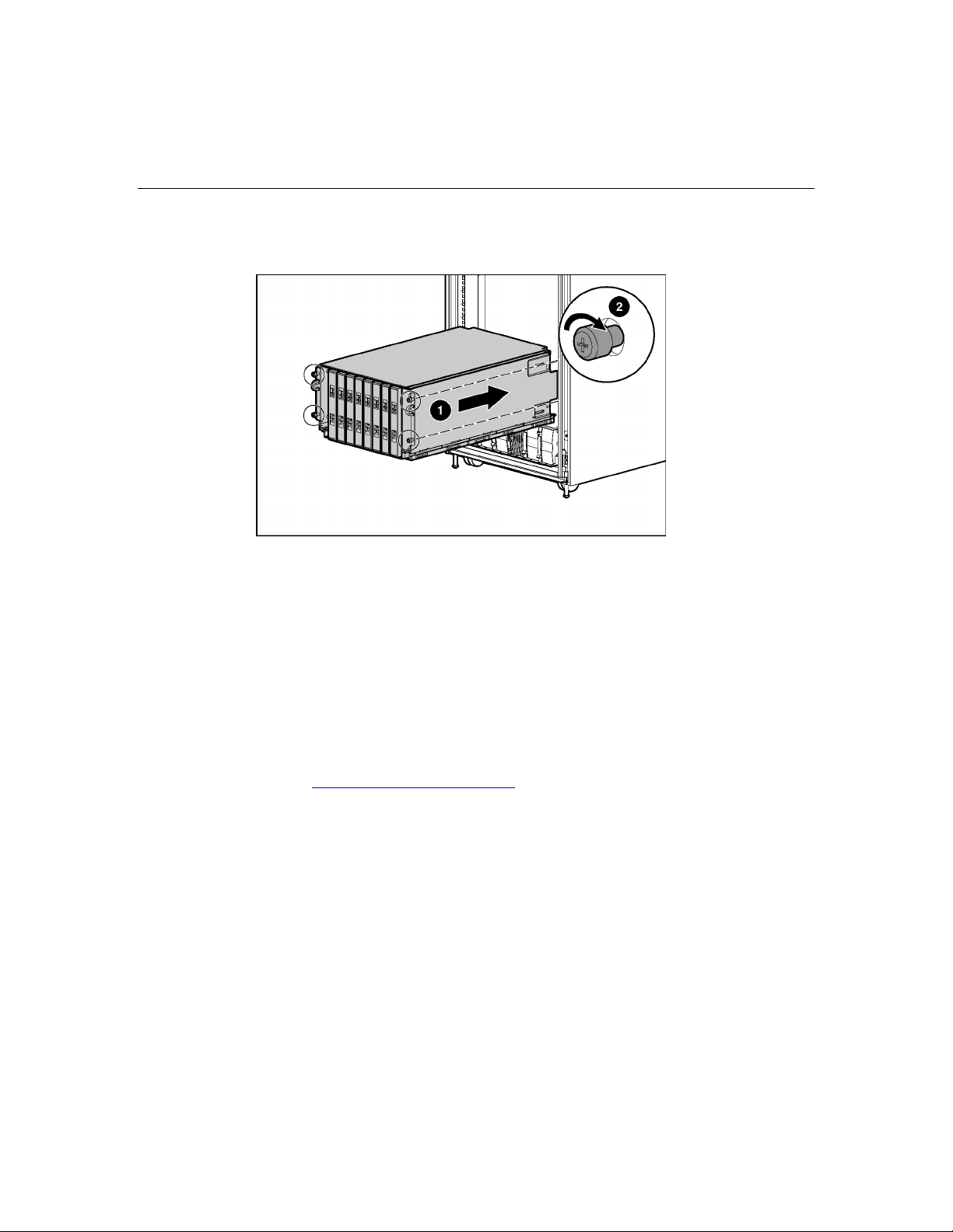
6. Tighten the thumbscrews to secure the enclosure in the rack.
Page 16
16 HP BladeSystem p-Class Enclosure Installation Guide
Measuring with the rack template
NOTE: A rack template is not provided with the 1U power supply
enclosure.
Rack templates ship with the bus bars and provide detailed instructions on where
to position bus bar hinges and enclosure rack rails. Each power supply enclosure
kit and server blade enclosure kit includes rack rails recommended for that
enclosure. The rack rails that ship with the HP BladeSystem 3U Power Enclosure
and HP BladeSystem p-Class Server Blade Enclosure are identical.
When installing multiple enclosures, install the rack rails for one enclosure, then
install the enclosure. Repeat for each additional enclosure.
Installing the rack rails and cage nuts
You must install two rack rails to support each enclosure. Rack rails have the
following features:
• • Adjustable depth of 60.96 cm to 91.44 cm (24 in to 36 in)
IMPORTANT: For proper bus bar installation and clearance, the rack
rail depth must be set from 73.66 cm to 76.20 cm (29 in to 30 in).
Depth indicator, visible in the middle of the rail
Page 17

Installing HP BladeSystem p-Class enclosures 17
• "L" and "R" markings to identify left and right rack rails (from the front of
the rack)
CAUTION: Always plan the rack installation so that the
heaviest item is on the bottom of the rack. Install the heaviest item first,
and continue to populate the rack from the bottom to the top.
Installing the HP BladeSystem p-Class 1U Power Enclosure rack rails
The HP BladeSystem p-Class 1U Power Enclosure uses HP 1U Adjustable
Toolless Rails. Refer to the installation instructions that are included with the rail
hardware kit for detailed installation instructions. Cage nuts are not used with the
HP BladeSystem p-Class 1U Power Enclosure.
NOTE: Power distribution devices (scalable bus bar and mini bus bar)
are not required when installing the HP BladeSystem 1U Power
Enclosure. The power enclosure is designed to connect directly to one
server blade enclosure.
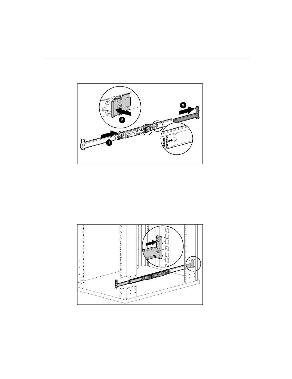
Installing the rack rails (3U power supply and server blade enclosures)
1. Adjust the rack rails to fit the rack, using the numbers on the rack rail as a
guide.
Page 18
18 HP BladeSystem p-Class Enclosure Installation Guide
NOTE: The depth of an HP or a Compaq branded rack (29 in) is clearly
indicated on the rack rails.
IMPORTANT: Numbers on the rack rail provide a gross adjustment of
the depth of the rack rail. You may need to adjust the rack rail depth
again to ensure a proper fit.
2. Install the right rack rail into the rack:
NOTE: Identify the left (L) and right (R) rack rails by markings stamped
into the sheet metal.
a. Insert the rear of the right rack rail into the rack at the marks you made
when measuring with the template.
Page 19
Installing HP BladeSystem p-Class enclosures 19
b. Compress the spring-loaded rack rail toward the rear of the rack.
c. Using the marks you made when measuring with the template, align the
front of the right rail with the holes and release the rail, allowing it to
lock into position.
d. Engage the locking gear.
CAUTION: Rack rails must be installed as tightly as possible.
Failure to obtain a proper fit may result in damage to equipment.
3. Repeat the preceding step for the left rack rail.
IMPORTANT: To ease installation, install all cage nuts for enclosures,
bus bar hinges, and cable brackets before installing the remaining
infrastructure.
4. Using the marks you made when measuring with the template, install the
cage nuts ("Installing the cage nuts" on page 20
) for enclosures, bus bar
hinges, and the cable bracket.
IMPORTANT: In AC power configurations, the bottom hinges for each
bus bar are installed on the ends of the power enclosure rack rails. The
rails have extrusions to align the hinges and holes to accept the screws.
In facility DC power configurations, you must install cage nuts to support
the bottom hinges. Refer to the template for hinge locations.
Page 20
20 HP BladeSystem p-Class Enclosure Installation Guide
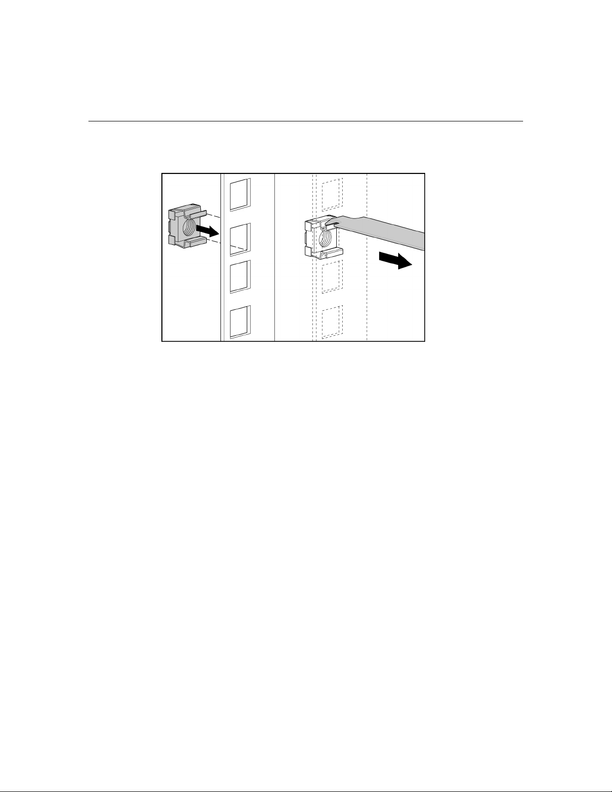
Installing the cage nuts
Installing HP BladeSystem p-Class enclosures into the rack
NOTE: Install all server blade enclosures before installing power
distribution devices at the rear of the rack.
Page 21
Installing HP BladeSystem p-Class enclosures 21
Installing HP BladeSystem p-Class 1U Power Enclosures
CAUTION: Always plan the rack installation so that the
heaviest item is on the bottom of the rack. Install the heaviest item first,
and continue to populate the rack from the bottom to the top.
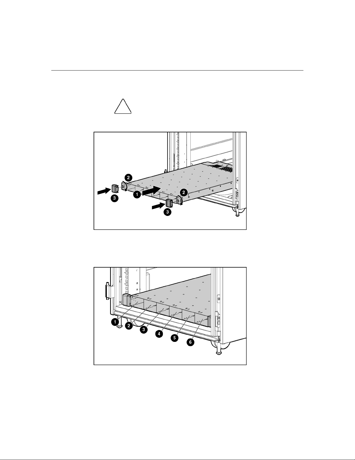
Identifying HP BladeSystem p-Class 1U Power Supply Enclosure bays
Page 22
22 HP BladeSystem p-Class Enclosure Installation Guide
Item Description Configuration
1 Power supply bay 1 Bus A
2 Power supply bay 2 Bus A
3 Power supply bay 3 Bus A
4 Power supply bay 4 Bus B
5 Power supply bay 5 Bus B
6 Power supply bay 6 Bus B
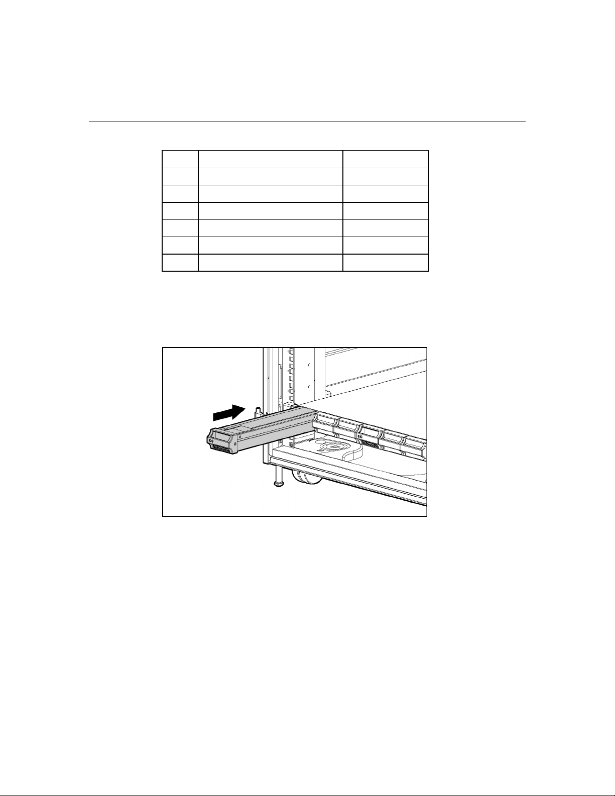
Installing an HP BladeSystem 1U Power Supply
If necessary, remove the power supply blank.
NOTE: Order the appropriate AC power cord if you are not using the
PDU solution to provide power to the equipment.
Page 23
Installing HP BladeSystem p-Class enclosures 23
Installing HP BladeSystem p-Class 3U Power Enclosures
CAUTION: Always plan the rack installation so that the
heaviest item is on the bottom of the rack. Install the heaviest item first,
and continue to populate the rack from the bottom to the top.
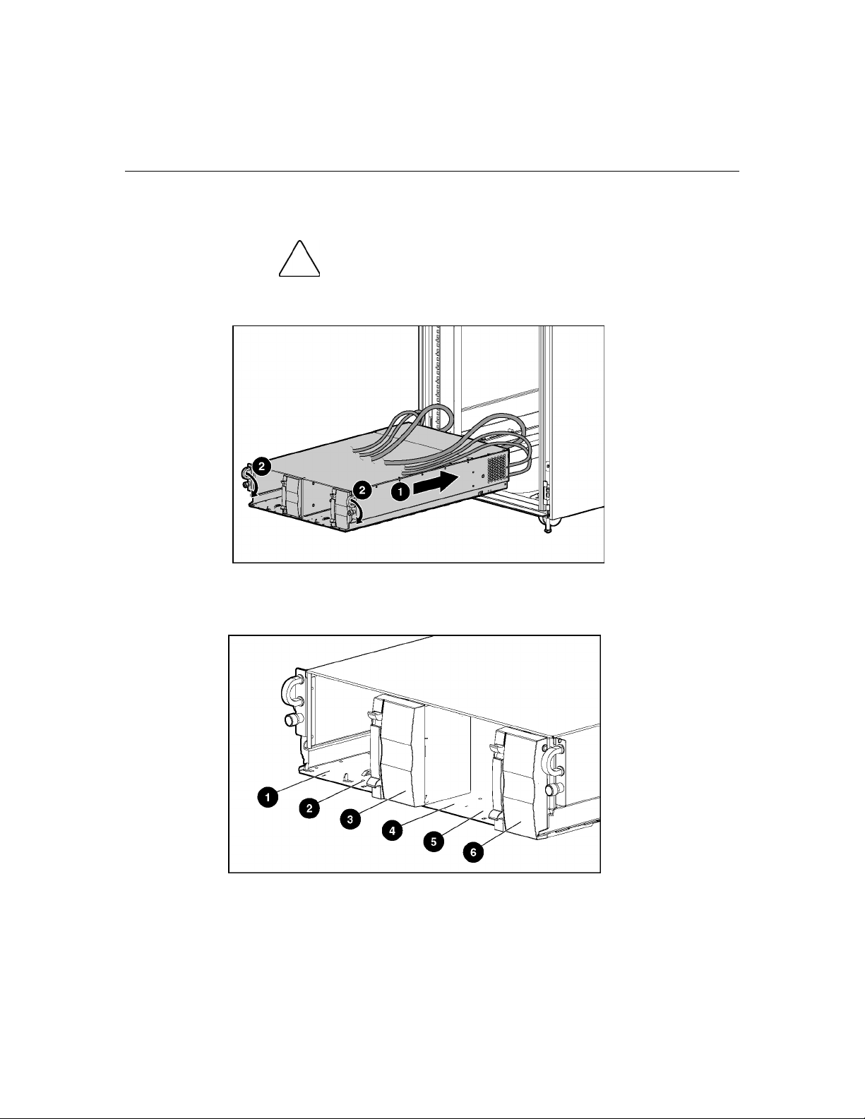
Identifying HP BladeSystem p-Class 3U Power Enclosure bays
Page 24
24 HP BladeSystem p-Class Enclosure Installation Guide
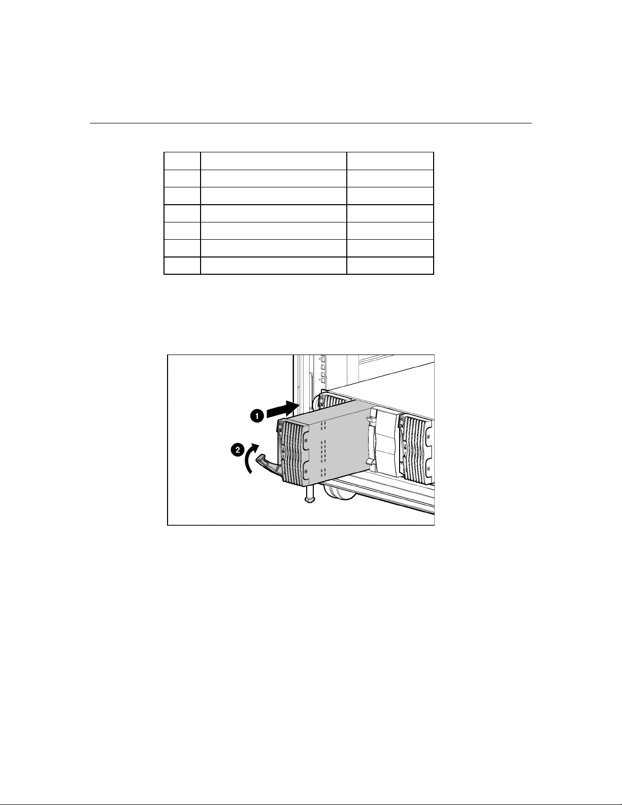
Item Description Configuration
1 Power supply bay 1 Bus A
2 Power supply bay 2 Bus A
3 Power supply bay 3 Bus A
4 Power supply bay 4 Bus B
5 Power supply bay 5 Bus B
6 Power supply bay 6 Bus B
Installing an HP BladeSystem 3U Power Supply
If necessary, remove the power supply blank.
Page 25
Installing HP BladeSystem p-Class enclosures 25
Installing HP BladeSystem p-Class Server Blade Enclosures
Installing interconnects
Each server blade enclosure requires a pair of interconnects and server blades to
provide network access for data transfer. The leftmost and rightmost bays of each
server blade enclosure are interconnect bays.
IMPORTANT: Interconnect options vary. A server blade enclosure
requires a pair of interconnects of the same type. Do not mix two types
of interconnects in the same enclosure. Refer to the documentation that
ships with the interconnect option or server blade option you have
selected. Additional information is available at the HP website
(http://www.hp.com/go/bizsupport
).
Page 26
26 HP BladeSystem p-Class Enclosure Installation Guide
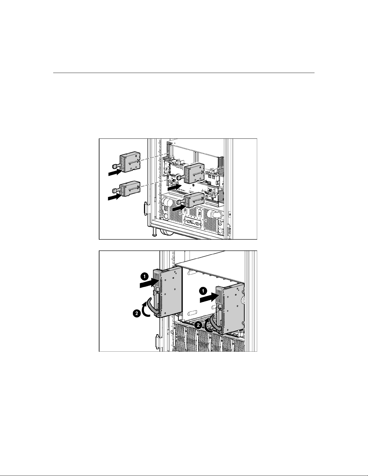
Installing HP BladeSystem interconnect modules and RJ-45 patch panels
NOTE: Always install the interconnect modules in the rear of the server
blade enclosure before installing the switch or patch panel in the front of
the server blade enclosure.
Page 27
Installing HP BladeSystem p-Class enclosures 27
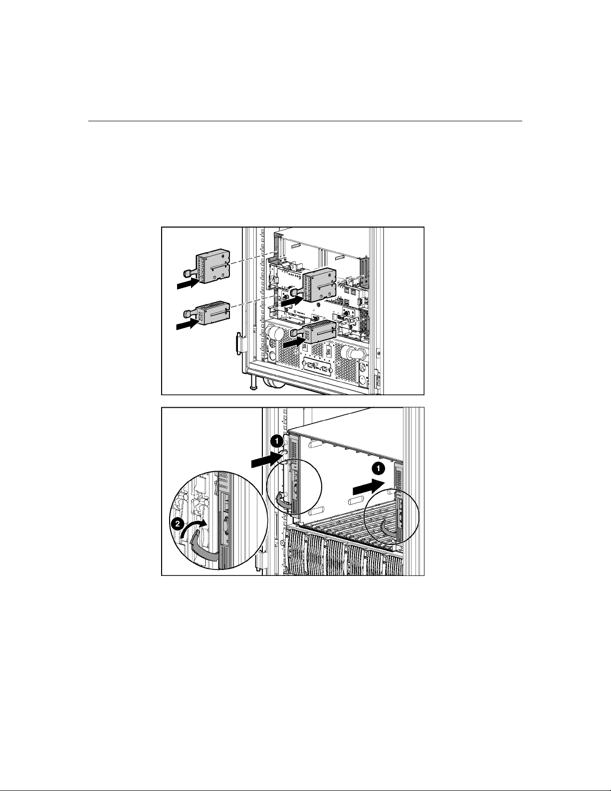
Installing HP BladeSystem interconnect modules and interconnect switches
NOTE: Always install the interconnect modules in the rear of the server
blade enclosure before installing the switch or patch panel in the front of
the server blade enclosure.
Page 28

Page 29

29
Cabling and powering up the system
In this section
System cabling overview..............................................................................................................29
Identifying HP BladeSystem p-Class 1U Power Enclosure components.....................................31
Identifying HP BladeSystem p-Class 3U Power Enclosure and Server Blade Enclosure
components...................................................................................................................................32
Installing power distribution devices............................................................................................33
Cabling the management modules................................................................................................39
Cabling the network to the system ...............................................................................................43
Connecting the HP BladeSystem p-Class 1U DC power cable to the server blade enclosure .....44
Connecting power cables to a mini bus bar..................................................................................44
Connecting power cables to a scalable bus bar ............................................................................47
Connecting facility DC power to the power distribution bus bars ...............................................51
Installing the cable bracket...........................................................................................................52
Configuration examples................................................................................................................52
Powering up the system................................................................................................................59
Completing the installation...........................................................................................................62
System cabling overview
After all system hardware is installed, cable the components. Refer to the HP
ProLiant BL System Best Practices Guide on the Documentation CD or the HP
website (http://www.hp.com
WARNING: To reduce the risk of electric shock or injury
due to high-current electrical energy, be sure that all power is
completely disconnected at the source before beginning any
power connections to the power bus bars or power bus box.
To cable the system:
1. Cable the management modules. Refer to "Cabling the management modules
(on page 39
)."
) for HP recommendations on cable ordering.
Page 30

30 HP BladeSystem p-Class Enclosure Installation Guide
2. Connect the network cables to the interconnects. Refer to the documentation
that came with the interconnects or to the HP ProLiant BL System Best
Practices Guide on the Documentation CD or on the HP website
(http://www.hp.com/go/bizsupport
WARNING: Be sure that all circuit breakers are locked in
the off position before connecting any power components.
).
3. If you are using a facility AC power source, complete the following steps:
a. If you are installing the HP BladeSystem p-Class 1U Power Enclosure,
connect the power cables from the power enclosure to the server blade
enclosure. Refer to "Connecting the HP BladeSystem p-Class 1U DC
Power Cable to the server blade enclosure (on page 44
b. If you are installing the HP BladeSystem p-Class 3U Power Enclosure in
a scalable bus bar configuration or Mini Bus Bar Dual Power Box
configuration, connect the load-balancing signal cable between power
enclosures. Refer to "Connecting the load-balancing signal cable (on
page 50
)."
c. Connect the bus bars or power bus boxes to the enclosures. Refer to
"Installing power distribution devices (on page 33
power couplers ("Installing the power connectors" on page 38
)."
)" and "Installing the
)."
4. If you are using a facility DC power source:
a. Connect the grounding cable to the server blade enclosures. Refer to
"Connecting facility DC power to the power distribution bus bars (on
page 51
)."
b. Install the facility DC cables. Refer to the documentation that ships with
the Facility DC Cable Kit.
c. Connect the bus bars or power bus boxes to the enclosures. Refer to
"Installing power distribution devices (on page 33
power couplers ("Installing the power connectors" on page 38
)" and "Installing the
)."
d. Install the cable bracket. Refer to the documentation that ships with the
brackets.
5. Connect to your facility AC or DC power source and power up the system.
Refer to the "Powering up the system (on page 59
)."
Page 31

Cabling and powering up the system 31
Identifying HP BladeSystem p-Class 1U Power Enclosure components
Item Description Cable type
1 DC output power connector for bus B DC power
cable
2 AC input power connector for bay 6 PDU power
cord
3 AC input power connector for bay 5 PDU power
cord
4 AC input power connector for bay 4 PDU power
cord
5 Power enclosure management link
connector (to enclosure below, if
necessary)
6 Power management module service
port
7 Power enclosure management link
connector (to server enclosure
above)
8 AC input power connector for bay 3 PDU power
RJ-45
management
link cable
—
RJ-45
management
link cable
cord
Page 32

32 HP BladeSystem p-Class Enclosure Installation Guide
Item Description Cable type
9 AC input power connector for bay 2 PDU power
cord
10 AC input power connector for bay 1 PDU power
cord
11 DC output power connector for bus A DC power
cable
Identifying HP BladeSystem p-Class 3U Power Enclosure and Server Blade Enclosure components
Item Description Cable type
1 Power zone configuration switch —
2 Server blade management link
connectors (top to enclosure above,
bottom to enclosure below)
3 iLO connector RJ-45
4 DC power input connectors for bus
A
5 Server blade enclosure grounding
cable screw
RJ-45
management
link cable
DC power
cable
—
Page 33

Cabling and powering up the system 33
Item Description Cable type
6 AC input power connector for bus A AC power
cord
7 DC output power connector for bus
A
8 Power enclosure grounding cable
screw
9 Power management link connectors
to enclosure above
10 Power management module service
port
11 Power enclosure AC circuit breakers
(to hot-plug power supplies) for bus
B (left) and bus A (right)
12 Power management link connectors
to enclosure below
13 DC output power connector for bus B DC power
14 Load balancing signal cable —
15 AC input power connector for bus B AC power
16 DC power input connectors for bus B DC power
DC power
cable
—
RJ-45
management
link cable
—
—
RJ-45
management
link cable
cable
cord
cable
17 Server blade management module
service port
—
Installing power distribution devices
NOTE: Power distribution devices (scalable bus bar and mini bus bar)
are not required when installing the HP BladeSystem 1U Power
Enclosure. The power enclosure is designed to connect directly to one
server blade enclosure.
NOTE: Other power distribution options may exist for the server blade.
Refer to the specific power distribution documentation for more
information.
Page 34

34 HP BladeSystem p-Class Enclosure Installation Guide
Solution Power
enclosures
supported
Server blade
enclosures
supported
Maximum
rack space
occupied
Scalable bus
2 5 36U
bar
Mini bus bar 1 3 21U
Mini bus bar* 2 3 24U
Power bus box 1 1 9U
* A Mini Bus Bar Dual Power Box supports two power enclosures attached to the mini bus
bar to enable a redundant AC power configuration.
Two mini bus bar configurations, each with one power enclosure and three server
blade enclosures, can be installed one above the other to fully populate a 42U
rack.
NOTE: Scalable and mini bus bars attach to the rack in the same
manner.
Page 35

Cabling and powering up the system 35
Installing a scalable bus bar kit
NOTE: Use the location marks made when you measured the rack with
the rack template.
Page 36

36 HP BladeSystem p-Class Enclosure Installation Guide
Installing a mini bus bar kit
NOTE: Use the location marks made when you measured the rack with
the rack template.
Installing a power bus box
WARNING: If using facility DC power, cables must be
connected by a licensed electrician or trained service personnel
familiar with high-power circuitry.
Page 37

Cabling and powering up the system 37
WARNING: Be sure that all circuit breakers are locked in
the off position before connecting any power components.
Page 38

38 HP BladeSystem p-Class Enclosure Installation Guide
Installing the power connectors
The power connectors are positioned to line up to adjacent server blade
enclosures.
WARNING: If using facility DC power, cables must be
connected by a licensed electrician or trained service personnel
familiar with high-power circuitry.
Page 39

Cabling and powering up the system 39
WARNING: Be sure that all circuit breakers are locked in
the off position before connecting any power components.
Cabling the management modules
The server blade management modules and power management modules are
cabled together in daisy-chain fashion to provide the management link. Each
management module has two management link connectors: one to connect to
enclosures above and one to connect to enclosures below. Cabling the
management modules enables the system to identify rack topology for power and
data management.
CAUTION: Do not install NIC cabling or telephone cabling into
the management link connectors; these devices are not supported.
When deploying the HP BladeSystem 1U Power Enclosure and attached server
enclosure into an existing installation, it is necessary to upgrade all management
module firmware on all enclosures to the latest version.
Management cabling guidelines
Observe the following guidelines for cabling the management modules.
Page 40

40 HP BladeSystem p-Class Enclosure Installation Guide
On the server blade management module:
•
The upper Management Link connects to the upper enclosure.
•
The lower Management Link connects to the lower enclosure.
•
The iLO port connects to the iLO network.
On the power management module:
•
The right management link connector connects to enclosures above the
module.
•
The left management link connector connects to enclosures below the
module.
Additional guidelines for a 42U solution
Observe the following additional guidelines for configuring a full-rack 42U
solution with two pairs of mini bus bars:
•
You must set the power configuration switches to establish the two power
zones. Refer to Power configuration switches (on page 72
) in this guide.
• You must cable the power management module in zone 2 (upper pair of mini
bus bars) to both adjacent server blade management modules, above and
below. This connection enables system management to establish a full-rack
topology.
Connecting the management module cables
NOTE: This section applies only to systems that are configured with an
enhanced server blade enclosure.
Page 41

Cabling and powering up the system 41
NOTE: Management modules are used only for information
management (asset tracking, for example). Disconnecting the
management module cabling does not affect system operation.
IMPORTANT: Improper cabling causes all the management link
connector LEDs on the management modules to flash.
Be sure the power configuration switches are set properly if you have a full-rack
solution with two pairs of mini bus bars. Refer to Power Configuration Switches
(on page 72
) in this guide.
Page 42

42 HP BladeSystem p-Class Enclosure Installation Guide
Connecting the HP BladeSystem p-Class 1U Management Link Cable
When deploying the HP BladeSystem 1U Power Enclosure and attached server
enclosure into an existing installation, it is necessary to upgrade all management
module firmware on all enclosures to the latest version.
IMPORTANT: In installations configured with the HP BladeSystem 1U
Power Enclosures and Power Supplies, the power zones are calculated
dynamically using the topology information from all the connected
enclosures. Disregard the power zone switch and LEDs on the
HP BladeSystem 1U Power Enclosure.
If deploying the HP BladeSystem 1U Power Enclosure into a rack installation
with other HP BladeSystem Enclosures, the enclosures can be connected to each
other with management link cables to identify rack topology. Refer to the
"Configuring the dynamic power saver (on page 57
)" section in this document.
Page 43

Cabling and powering up the system 43
Connecting to iLO
NOTE: This section applies only to systems that are configured with an
enhanced server blade enclosure.
Cabling the network to the system
Cable the interconnects to the network. Refer to the supporting documentation
for specific details on cabling the interconnects.
Page 44

44 HP BladeSystem p-Class Enclosure Installation Guide
Connecting the HP BladeSystem p-Class 1U DC power cable to the server blade enclosure
Connecting power cables to a mini bus bar
Connect the power cables to the mini bus bar.
Page 45

Cabling and powering up the system 45
Removing the mini bus bar cover
Connecting power cables to the mini bus bar
WARNING: If using facility DC power, cables must be
connected by a licensed electrician or trained service personnel
familiar with high-power circuitry.
Page 46

46 HP BladeSystem p-Class Enclosure Installation Guide
NOTE: If you are connecting two HP BladeSystem 3U Power
enclosures to mini bus bars, refer to the HP BladeSystem Mini Bus Bar
Dual Power Kit Installation Instructions or to the HP BladeSystem
p-Class Enclosure Installation Guide.
Replacing the mini bus bar cover
Page 47

Cabling and powering up the system 47
Securing the mini bus bars
Connecting power cables to a scalable bus bar
Connect the DC power cables to the scalable bus bar.
Page 48

48 HP BladeSystem p-Class Enclosure Installation Guide
Removing the scalable bus bar covers
WARNING: If using facility DC power, cables must be
connected by a licensed electrician or trained service personnel
familiar with high-power circuitry.
Connecting power cables to the scalable bus bar
Page 49

Cabling and powering up the system 49
Replacing the scalable bus bar cover
Page 50

50 HP BladeSystem p-Class Enclosure Installation Guide
Securing the scalable bus bars
Connecting the load-balancing signal cable
When a power zone is configured with two HP BladeSystem 3U Power
Enclosures, the load-balancing signal cable must be used to enable the power
enclosures to balance their power output for the system power demand in that
power zone.
IMPORTANT: If the load-balancing signal cable is not installed, the
management software issues alerts.
Page 51

Cabling and powering up the system 51
IMPORTANT: If the configuration does not include HP BladeSystem
p-Class 3U Power Enclosures, no load-balancing signal cables are
necessary.
Connecting facility DC power to the power distribution bus bars
Install the facility DC cable option kit. Refer to the documentation that ships with
that kit.
The grounding cable satisfies enclosure-to-enclosure grounding requirements in
facility DC power environments. Each type of bus bar supports a different
number of enclosures; therefore, each Facility DC Cable Option Kit contains a
grounding cable to support the appropriate number of enclosures.
WARNING: The ground cable must be connected to each
enclosure in the rack and to a suitable ground (earth) terminal
located within the rack or cabinet. The terminal in the rack must be
connected to a suitable building ground (earth) terminal in
accordance with local, regional, or national electrical codes or
regulations. Do not rely on the rack or cabinet chassis to provide
adequate continuity of the rack ground connection.
Page 52

52 HP BladeSystem p-Class Enclosure Installation Guide
WARNING: If using facility DC power, cables must be
connected by a licensed electrician or trained service personnel
familiar with high-power circuitry.
To connect the grounding cable:
1. Insert the mounting screw through the grounding cable lead and into the
enclosure (1).
2. Tighten the mounting screw to secure the grounding cable to the enclosure
(2).
3. Repeat steps 1 and 2 as needed for the configuration until all enclosures in
the rack are connected by the grounding cable.
4. Connect the lower end of the grounding cable to the facility grounding
connection.
Installing the cable bracket
Install the cable bracket (optional) provided with each power distribution kit.
Configuration examples
Refer to the following examples for typical HP BladeSystem configurations:
Page 53

Cabling and powering up the system 53
• Scalable bus bar configuration example (on page 53)
• Two mini bus bar configuration example (on page 54)
• Redundant mini bus bar configuration example (on page 55
• Full rack 42U solution with two pairs of mini bus bars (on page 56)
• Configuring the Dynamic Power Saver (on page 57)
Scalable bus bar configuration example
CAUTION: Always use blanking panels to fill empty vertical
spaces in the rack. This arrangement ensures proper airflow. Using a
rack without blanking panels results in improper cooling that can lead to
thermal damage.
)
Page 54

54 HP BladeSystem p-Class Enclosure Installation Guide
CAUTION: Always use blanks to fill empty spaces in
enclosures. This arrangement ensures proper airflow. Using an
enclosure without the proper blanks results in improper cooling that can
lead to thermal damage.
Two mini bus bar configuration example
CAUTION: Always use blanking panels to fill empty vertical
spaces in the rack. This arrangement ensures proper airflow. Using a
rack without blanking panels results in improper cooling that can lead to
thermal damage.
Page 55

Cabling and powering up the system 55
CAUTION: Always use blanks to fill empty spaces in
enclosures. This arrangement ensures proper airflow. Using an
enclosure without the proper blanks results in improper cooling that can
lead to thermal damage.
Redundant mini bus bar configuration example
The configurations illustrated in this document are non-redundant AC mini bus
bar configurations. To obtain AC redundancy, you need the AC redundant mini
bus bar box. Refer to the documentation supplied with the AC redundant mini
bus bar box and to the HP ProLiant BL System Best Practices Guide.
Page 56

56 HP BladeSystem p-Class Enclosure Installation Guide
Full rack 42U solution with two pairs of mini bus bars
Observe the following additional guidelines for configuring a full-rack 42U
solution with two pairs of mini bus bars:
• • Set the power configuration switches to establish the two power zones.
Cable the power management module in zone 2 (upper pair of mini bus bars)
to both adjacent server blade management modules, above and below. This
connection enables system management to establish a full rack topology.
Page 57

Cabling and powering up the system 57
Item Description
1 Power zone 2
2 Zone 2 switches in the up (secondary) position
3 Power zone 1
4 Zone 1 switches in the down (default) position
IMPORTANT: In installations configured with the HP BladeSystem 1U
Power Enclosures and Power Supplies, the power zones are calculated
dynamically using the topology information from all the connected
enclosures. Disregard the power zone switch and LEDs on the
HP BladeSystem 1U Power Enclosure.
For more information on configuring the power zones, refer to the HP ProLiant
BL System Best Practices Guide.
Configuring the Dynamic Power Saver
NOTE: The Dynamic Power Saver is a feature of the HP BladeSystem
p-Class 1U Power Supply Enclosure.
NOTE: The Dynamic Power Saver configures the available power
supplies to operate at maximum efficiency.
When the Dynamic Power Saver feature is enabled, the total enclosure power
consumption is monitored in real time. Power supplies are placed in a standby
condition when the power demand from the server enclosure is low. When power
demand increases, the standby power supplies instantaneously deliver the
required power. This enables the enclosure to operate at optimum efficiency.
Page 58

58 HP BladeSystem p-Class Enclosure Installation Guide
To configure the Dynamic Power Saver, remove the power enclosure
management module.
Use the following figure and table to identify the Dynamic Power Saver switch
location and function.
Position Function
1 Dynamic Power Saver disabled (default)
2 Dynamic Power Saver enabled
Page 59

Cabling and powering up the system 59
Position Function
3 Reserved (off=default)
Powering up the system
WARNING: Be sure that all circuit breakers are locked in
the off position before connecting any power components.
Refer to the following procedures to power up your HP BladeSystem installation:
• Powering up the system (HP BladeSystem p-Class 1U Power Enclosure) (on
page 59
• Powering up the system (HP BladeSystem p-Class 3U Power Enclosure) (on
page 60
• Powering up the system (facility DC) (on page 61)
)
)
Powering up the system (HP BladeSystem p-Class 1U Power Enclosure)
NOTE: Order the appropriate AC power cord if you are not using the
PDU solution to provide power to the equipment.
If you have installed the 1U power enclosure:
1. Be sure all power supplies are seated in the power enclosure.
2. Connect each PDU Power Cord to the power enclosure.
3. Connect each PDU Power Cord to the PDU.
4. Connect the PDU to the facility power connection.
5. Apply power to the facility power connection, if necessary.
6. Be sure that the hot-plug power supply LEDs and power enclosure DC power
LEDs are illuminated green. Refer to "LEDs, buttons, and switches (on page
)" or to the documentation included with the HP BladeSystem p-Class 1U
63
Power Enclosure.
Page 60

60 HP BladeSystem p-Class Enclosure Installation Guide
7. Be sure that the server blade enclosure DC power LEDs are illuminated
green. Refer to "LEDs, buttons, and switches (on page 63
)" or to the
documentation included with the HP BladeSystem p-Class Server Blade
Enclosure.
Power is now applied to all system hardware.
Powering up the system (HP BladeSystem p-Class 3U Power Enclosure)
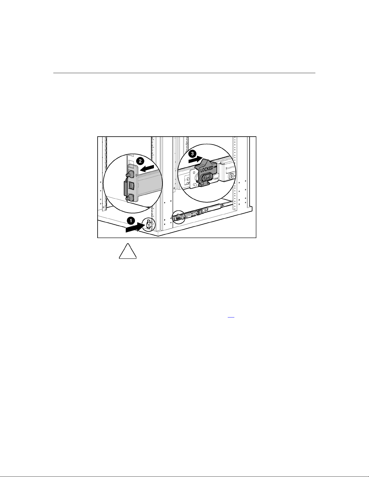
If you have installed the HP BladeSystem p-Class 3U Power Enclosure:
1. Be sure all power supplies are seated in the power enclosure.
2. Connect the power cords to the AC power source.
3. Apply power to the facility power connection, if necessary.
4. Unlock the circuit breakers on the power enclosure.
5. Toggle the switches to the on position. This action applies AC power to the
hot-plug power supplies.
6. Lock the switch in the on position.
Page 61

Cabling and powering up the system 61
7. Be sure that the hot-plug power supply LEDs, power enclosure DC power
LEDs, and bus bar power LEDs are illuminated green. Refer to the "LEDs,
buttons, and switches (on page 63
)" or to the documentation included with
the HP BladeSystem p-Class 3U Power Enclosure.
8. Unlock the circuit breaker switches on the bus bars or power bus boxes and
toggle the switches to the on position. This action applies DC power to the
server blade enclosures.
IMPORTANT: Only unlock circuit breakers for couplers that are
attached to a server blade enclosure.
9. Be sure that the server blade enclosure DC power LEDs are illuminated
green. Refer to "LEDs, buttons, and switches (on page 63
)" or to the
documentation included with the HP BladeSystem p-Class Server Blade
Enclosure.
NOTE: Circuit breakers continue to function in the event of an overload
condition even if they are locked.
IMPORTANT: Be sure to lock all the circuit breaker switches in the on
position. This action prevents anyone from accidentally powering down
the system.
Power is now applied to all system hardware.
Powering up the system (facility DC)
If you are using a facility DC power source:
1. Connect the power cables to the DC power source.
2. Apply power to the facility power connection, if necessary.
IMPORTANT: Only unlock circuit breakers for couplers that are
attached to a server blade enclosure.
3. Unlock the circuit breaker switches on the bus bars or power bus boxes and
toggle the switches to the on position. This action applies DC power to the
server blade enclosures.
IMPORTANT: Be sure to lock all the circuit breaker switches in the on
position. This action prevents anyone from accidentally powering down
the system.
NOTE: Circuit breakers continue to function in the event of an overload
condition even if they are locked.
Page 62

62 HP BladeSystem p-Class Enclosure Installation Guide
4. Be sure that the server blade enclosure DC power LEDs are illuminated
green. Refer to "LEDs, buttons, and switches (on page 63
documentation included with the HP BladeSystem p-Class Server Blade
Enclosure.
Power is now applied to all system hardware.
Completing the installation
To complete the BladeSystem installation, perform the following tasks:
•
Build the management environment.
•
Name the server blade enclosures.
•
Name the server blade components.
•
Update the component firmware.
•
Install operating systems on the server blades.
•
Deploy application software onto the server blades.
)" or to the
•
Establish the SAN environment (optional).
For more information, refer to the HP Remote Insight Lights-Out Edition User
Guide, the HP Remote Insight Lights-Out Edition II User Guide, or the
HP Integrated Lights-Out User Guide available at the Remote Management
website (http://www.hp.com/servers/lights-out
).
Page 63

63
LEDs, buttons, and switches
In this section
LEDs.............................................................................................................................................63
Buttons and switches ....................................................................................................................71
LEDs
Server blade enclosure LEDs
The system contains several sets of LEDs that indicate the status and settings of
hardware components. Use the following sections to determine the location and
functions of LEDs on system components.
For information about LEDs on server blades, interconnect modules, hard drives,
and other devices, refer to the documentation supplied with each device.
The server blade enclosure has two LEDs that provide the status of DC power
input. Use the following figure and table to identify LED locations and functions.
Page 64

64 HP BladeSystem p-Class Enclosure Installation Guide
Item LED Description Status
1 Bus B power Off = No power available
Green = Power available
Red = Polarity reversed
2 Bus A power Off = No power available
Green = Power available
Red = Polarity reversed
Server blade management module LEDs
The server blade management module has LEDs for identification, power status,
and management activity. Use the following figure and table to identify LED
locations and functions.
Item LED Description Status
1 Fault status LED Red = Fault process activity
Off = No fault process
activity
Page 65

LEDs, buttons, and switches 65
Item LED Description Status
2 Unit identification Blue = Identified
Off = No active remote
management
3 Power LED Off = No power
Green = Management
module is powered up
4/5 Power configuration Off/Green = Power zone 1
(default)
Green/Green = Power zone
2 (secondary)
6 Management link
activity LED
7 Management link LED Green = Network linked*
8 iLO activity Green = Activity
9 iLO Link Green = Network linked
* All management link connector LEDs flash on the server blade management modules
and power management modules when management modules are cabled improperly.
Amber = Activity*
Off = No link or activity
Off = No link
Off = No activity
Off = No link
Power management module LEDs
The power management module has LEDs for identification, power status, and
management activity.
IMPORTANT: If the power configuration switch is set improperly, all
power management module management link connector LEDs flash.
IMPORTANT: If management modules are cabled improperly, all
management link connector LEDs flash on all management modules.
Page 66

66 HP BladeSystem p-Class Enclosure Installation Guide
Use the following figure and table to identify LED locations and functions.
Item LED Description Status
1 Management link
activity LED
2 Management link LED Green = Network linked*
3 Power Off = No power
4 Fault status LED Red = Fault process activity
5 UID LED Blue = Identified
6/7 Power configuration Off/Green = Power zone 1
Amber = Network activity*
Off = No link or activity
Off = No link
Green = Management
module is powered up
Off = No fault process
activity
Off = Not identified
(default)
Green/Green = Power zone
2 (secondary)
Page 67

LEDs, buttons, and switches 67
* All management link connector LEDs flash on all management modules when
management modules are cabled improperly. Management link connector LEDs flash on
the power management module only when power configuration switches are set
improperly.
HP BladeSystem p-Class 1U Power Enclosure LEDs
Use the following figure and table to identify LED locations and functions.
Item LED Description Status
1 Bus B DC power
LED
2 Management link
activity LED
3 Management link
LED
4 Power LED Off = No power
Off = No DC power available
Green = DC power available
Amber flashing = Network
activity
Off = No link or activity
Green = Network linked
Off = No link
Green = Management module
is powered up
Page 68

68 HP BladeSystem p-Class Enclosure Installation Guide
Item LED Description Status
5 Fault status LED Red flashing = Fault process
activity
Off = No fault process activity
6 UID LED Blue = Identified
Off = No active remote
management
7, 8 Power zone LEDs See note 1
9 Management link
activity LED
Amber flashing = Network
activity
Off = No link or activity
10 Management link
LED
11 Bus A DC power
LED
1
Power zones are automatically configured based on the location of the enclosures in the
Green = Network linked
Off = No link
Off = No DC power available
Green = DC power available
rack and the management link connections. Disregard the power zone switch and LEDs
on the HP BladeSystem 1U Power Enclosure.
Page 69

LEDs, buttons, and switches 69
HP BladeSystem p-Class 3U Power Enclosure LEDs
The power enclosure has two LEDs, one for each bus, to indicate DC power
presence. Use the following figure and table to identify LED locations and
functions.
Item LED Description Status
1 Bus B DC power Off = No DC power available
Green = DC power available
2 Bus A DC power Off = No DC power available
Green = DC power available
Page 70

70 HP BladeSystem p-Class Enclosure Installation Guide
HP BladeSystem p-Class 1U Power Supply LEDs
The power supply has two LEDs to indicate the power supply status. Use the
following figure and table to identify LED locations and functions.
NOTE: The Dynamic Power Saver configures the available power
supplies to operate at maximum efficiency.
Condition Power LED (1) Fault LED (2)
No AC Off Off
AC available, power
supply in standby mode
Power supply on,
1
Flashing
(Green)
Off
Green Off
delivering power
Power supply fault
condition
1
This condition will occur when the Dynamic Power Saver is enabled.
2
To reset the power supply overload warning, remove AC power or hot-unplug and hot-
2
Off Amber
plug the power supply if more than one power supply in the enclosure is delivering power
to the server enclosure.
Page 71

LEDs, buttons, and switches 71
HP BladeSystem p-Class 3U Power Supply LEDs
The power enclosure has two LEDs, one for each bus, to indicate DC power
presence. Use the following figure and table to identify LED locations and
functions.
Item LED Description Status
1 Bus B DC power Off = No DC power available
2 Bus A DC power Off = No DC power available
Buttons and switches
The system contains switches that reset the systems, identify components of the
systems, and establish the power zone settings. Use the following sections to
determine the location and functions of these switches on system components.
For information about switches on server blades, interconnect modules, hard
drives, and other devices, refer to the documentation supplied with each device.
Green = DC power available
Green = DC power available
Page 72

72 HP BladeSystem p-Class Enclosure Installation Guide
Reset and UID buttons
Each management module contains a reset button and UID button. Use the
following figure and table to identify button locations and functions.
Item Description Function
1 Reset button Reinitializes management
2 UID button Toggles UID LED between on
Power configuration switches
IMPORTANT: In installations configured with the HP BladeSystem 1U
Power Enclosures and Power Supplies, the power zones are calculated
dynamically using the topology information from all the connected
enclosures. Disregard the power zone switch and LEDs on the
HP BladeSystem 1U Power Enclosure.
functions
and off
Page 73

LEDs, buttons, and switches 73
The server blade management modules and power management modules have a
two-position switch that identifies the use of single or multiple power zones in
the rack environment. In installations configured with HP BladeSystem p-Class
3U Power Supply Enclosures, you must set these switches at the time of
installation for the system to recognize multiple power zones and rack topology
properly.
The zone 1 switch setting is the default position. It is used for scalable bus bar,
single mini bus bar, and power bus box solutions. The zone 2 switch setting is
only used for a secondary power zone when you configure a full-rack 42U
solution with two pairs of mini bus bars.
Use the following figure and table to identify switch locations and functions.
Item Description Function
1 Reset switch Reinitializes management
functions
2 UID switch Toggles UID LED between on
and off
After the initial power-up, use the LEDs to verify correct switch settings. Refer
to the "Server blade management module LEDs (on page 64
management module LEDs (on page 65
)" sections in this guide.
)" and "Power
Page 74

74 HP BladeSystem p-Class Enclosure Installation Guide
IMPORTANT: All power configuration switches in the same zone must
be set to the same position. The system issues alerts and the
management link connector LEDs on the power management modules
flash when these switches are set improperly.
To set the switches for multiple power zones, use the following example and
figure.
Example: A full-rack 42U solution with two pairs of mini bus bars requires two
power zones. To distinguish the two power zones, set all the power configuration
switches on management modules in the upper zone (zone 2) to the up position;
the power configuration switches on the management modules in the lower zone
(zone 1) remain in the down (default) position.
Page 75

LEDs, buttons, and switches 75
Item
1 Power zone 2
2 Zone 2 switches in the up (secondary) position
3 Power zone 1
4 Zone 1 switches in the down (default) position
Page 76

Page 77

77
Troubleshooting
In this section
Troubleshooting resources............................................................................................................77
Important safety information........................................................................................................77
Troubleshooting resources
NOTE: For common troubleshooting procedures, the term "server" is
used to mean servers and server blades.
The HP ProLiant Servers Troubleshooting Guide provides simple procedures for
resolving common problems as well as a comprehensive course of action for
fault isolation and identification, error message interpretation, issue resolution,
and software maintenance.
To obtain the guide, refer to any of the following sources and then select the HP
ProLiant Servers Troubleshooting Guide.
•
The server-specific Documentation CD
•
The Business Support Center on the HP website
(http://www.hp.com/support
). You can find the guide by using the navigation
features on the HP website.
• The Technical Documentation website (http://www.docs.hp.com
Enterprise Servers, Workstations and Systems Hardware, and then the
appropriate server.
Important safety information
Familiarize yourself with the safety information in the following sections before
troubleshooting the server.
). Select
Page 78

78 HP BladeSystem p-Class Enclosure Installation Guide
Important safety information
Before servicing this product, read the Important Safety Information document
provided with the server.
Symbols on equipment
The following symbols may be placed on equipment to indicate the presence of
potentially hazardous conditions.
This symbol indicates the presence of hazardous
energy circuits or electric shock hazards. Refer all servicing to
qualified personnel.
WARNING: To reduce the risk of injury from electric shock
hazards, do not open this enclosure. Refer all maintenance,
upgrades, and servicing to qualified personnel.
This symbol indicates the presence of electric
shock hazards. The area contains no user or field serviceable
parts. Do not open for any reason.
WARNING: To reduce the risk of injury from electric shock
hazards, do not open this enclosure.
This symbol on an RJ-45 receptacle indicates a
network interface connection.
WARNING: To reduce the risk of electric shock, fire, or damage to
the equipment, do not plug telephone or telecommunications
connectors into this receptacle.
This symbol indicates the presence of a hot surface
or hot component. If this surface is contacted, the potential for
injury exists.
WARNING: To reduce the risk of injury from a hot component,
allow the surface to cool before touching.
Page 79

Troubleshooting 79
21.55 - 36.33 kg
47.5 - 80.1 lbs.
This symbol indicates that the component exceeds the
recommended weight for one individual to handle safely.
WARNING: To reduce the risk of personal injury or damage to the
equipment, observe local occupational health and safety
requirements and guidelines for manual material handling.
These symbols, on power supplies or
systems, indicate that the equipment is supplied by multiple
sources of power.
WARNING: To reduce the risk of injury from electric shock,
remove all power cords to completely disconnect power from the
system.
Warnings and cautions
WARNING: Only authorized technicians trained by HP
should attempt to repair this equipment. All troubleshooting and
repair procedures are detailed to allow only subassembly/modulelevel repair. Because of the complexity of the individual boards
and subassemblies, no one should attempt to make repairs at the
component level or to make modifications to any printed wiring
board. Improper repairs can create a safety hazard.
WARNING: To reduce the risk of personal injury or
damage to the equipment, be sure that:
Page 80

80 HP BladeSystem p-Class Enclosure Installation Guide
The leveling feet are extended to the floor. •
•
The full weight of the rack rests on the leveling feet.
•
The stabilizing feet are attached to the rack if it is a single-rack
installation.
•
The racks are coupled together in multiple-rack installations.
•
Only one component is extended at a time. A rack may become
unstable if more than one component is extended for any
reason.
WARNING: To reduce the risk of electric shock or damage
to the equipment:
Do not disable the power cord grounding plug. The grounding
•
plug is an important safety feature.
•
Plug the power cord into a grounded (earthed) electrical outlet
that is easily accessible at all times.
•
Unplug the power cord from the power supply to disconnect
power to the equipment.
•
Do not route the power cord where it can be walked on or
pinched by items placed against it. Pay particular attention to
the plug, electrical outlet, and the point where the cord extends
from the server.
21.55 - 36.33 kg
47.5 - 80.1 lbs.
WARNING: To reduce the risk of personal injury or damage to the
equipment:
Page 81

Troubleshooting 81
Observe local occupation health and safety requirements and
•
guidelines for manual handling.
•
Obtain adequate assistance to lift and stabilize the chassis
during installation or removal.
•
The server is unstable when not fastened to the rails.
•
When mounting the server in a rack, remove the power
supplies and any other removable module to reduce the overall
weight of the product.
CAUTION: To properly ventilate the system, you must provide
at least 7.6 cm (3.0 in) of clearance at the front and back of the server.
CAUTION: The server is designed to be electrically grounded
(earthed). To ensure proper operation, plug the AC power cord into a
properly grounded AC outlet only.
Page 82

Page 83

83
Regulatory compliance notices
In this section
Regulatory compliance identification numbers............................................................................83
Federal Communications Commission notice..............................................................................84
Declaration of conformity for products marked with the FCC logo, United States only .............85
Modifications................................................................................................................................86
Cables ...........................................................................................................................................86
Canadian notice (Avis Canadien).................................................................................................86
European Union regulatory notice................................................................................................87
Japanese notice .............................................................................................................................88
Power cord statement for Japan....................................................................................................88
BSMI notice..................................................................................................................................88
Korean notice A&B......................................................................................................................89
Laser compliance..........................................................................................................................89
Battery replacement notice ...........................................................................................................90
Taiwan battery recycling notice ...................................................................................................91
Regulatory compliance identification numbers
For the purpose of regulatory compliance certifications and identification, this
product has been assigned a unique regulatory model number. The regulatory
model number can be found on the product nameplate label, along with all
required approval markings and information. When requesting compliance
information for this product, always refer to this regulatory model number. The
regulatory model number is not the marketing name or model number of the
product.
Page 84

84 HP BladeSystem p-Class Enclosure Installation Guide
Federal Communications Commission notice
Part 15 of the Federal Communications Commission (FCC) Rules and
Regulations has established Radio Frequency (RF) emission limits to provide an
interference-free radio frequency spectrum. Many electronic devices, including
computers, generate RF energy incidental to their intended function and are,
therefore, covered by these rules. These rules place computers and related
peripheral devices into two classes, A and B, depending upon their intended
installation. Class A devices are those that may reasonably be expected to be
installed in a business or commercial environment. Class B devices are those that
may reasonably be expected to be installed in a residential environment (for
example, personal computers). The FCC requires devices in both classes to bear
a label indicating the interference potential of the device as well as additional
operating instructions for the user.
FCC rating label
The FCC rating label on the device shows the classification (A or B) of the
equipment. Class B devices have an FCC logo or ID on the label. Class A
devices do not have an FCC logo or ID on the label. After you determine the
class of the device, refer to the corresponding statement.
Class A equipment
This equipment has been tested and found to comply with the limits for a Class A
digital device, pursuant to Part 15 of the FCC Rules. These limits are designed to
provide reasonable protection against harmful interference when the equipment is
operated in a commercial environment. This equipment generates, uses, and can
radiate radio frequency energy and, if not installed and used in accordance with
the instructions, may cause harmful interference to radio communications.
Operation of this equipment in a residential area is likely to cause harmful
interference, in which case the user will be required to correct the interference at
personal expense.
Page 85

Regulatory compliance notices 85
Class B equipment
This equipment has been tested and found to comply with the limits for a Class B
digital device, pursuant to Part 15 of the FCC Rules. These limits are designed to
provide reasonable protection against harmful interference in a residential
installation. This equipment generates, uses, and can radiate radio frequency
energy and, if not installed and used in accordance with the instructions, may
cause harmful interference to radio communications. However, there is no
guarantee that interference will not occur in a particular installation. If this
equipment does cause harmful interference to radio or television reception, which
can be determined by turning the equipment off and on, the user is encouraged to
try to correct the interference by one or more of the following measures:
•
Reorient or relocate the receiving antenna.
•
Increase the separation between the equipment and receiver.
•
Connect the equipment into an outlet on a circuit that is different from that to
which the receiver is connected.
•
Consult the dealer or an experienced radio or television technician for help.
Declaration of conformity for products marked with the FCC logo, United States only
This device complies with Part 15 of the FCC Rules. Operation is subject to the
following two conditions: (1) this device may not cause harmful interference, and
(2) this device must accept any interference received, including interference that
may cause undesired operation.
For questions regarding this product, contact us by mail or telephone:
•
Hewlett-Packard Company
P. O. Box 692000, Mail Stop 530113
Houston, Texas 77269-2000
•
1-800-HP-INVENT (1-800-474-6836). (For continuous quality
improvement, calls may be recorded or monitored.)
For questions regarding this FCC declaration, contact us by mail or telephone:
Page 86

86 HP BladeSystem p-Class Enclosure Installation Guide
• • Hewlett-Packard Company
P. O. Box 692000, Mail Stop 510101
Houston, Texas 77269-2000
1-281-514-3333
To identify this product, refer to the part, series, or model number found on the
product.
Modifications
The FCC requires the user to be notified that any changes or modifications made
to this device that are not expressly approved by Hewlett-Packard Company may
void the user’s authority to operate the equipment.
Cables
Connections to this device must be made with shielded cables with metallic
RFI/EMI connector hoods in order to maintain compliance with FCC Rules and
Regulations.
Canadian notice (Avis Canadien)
Class A equipment
This Class A digital apparatus meets all requirements of the Canadian
Interference-Causing Equipment Regulations.
Cet appareil numérique de la classe A respecte toutes les exigences du
Règlement sur le matériel brouilleur du Canada.
Class B equipment
This Class B digital apparatus meets all requirements of the Canadian
Interference-Causing Equipment Regulations.
Cet appareil numérique de la classe B respecte toutes les exigences du Règlement
sur le matériel brouilleur du Canada.
Page 87

Regulatory compliance notices 87
European Union regulatory notice
This product complies with the following EU Directives:
• • Low Voltage Directive 73/23/EEC
EMC Directive 89/336/EEC
Compliance with these directives implies conformity to applicable harmonized
European standards (European Norms) which are listed on the EU Declaration of
Conformity issued by Hewlett-Packard for this product or product family.
This compliance is indicated by the following conformity marking placed on the
product:
This marking is valid for non-Telecom products and EU harmonized Telecom
products (e.g. Bluetooth).
This marking is valid for EU non-harmonized Telecom products.
*Notified body number (used only if applicable—refer to the product label)
Page 88

88 HP BladeSystem p-Class Enclosure Installation Guide
Japanese notice
Power cord statement for Japan
BSMI notice
Page 89

Regulatory compliance notices 89
Korean notice A&B
Class A equipment
Class B equipment
Laser compliance
This product may be provided with an optical storage device (that is, CD or DVD
drive) and/or fiber optic transceiver. Each of these devices contains a laser that is
classified as a Class 1 Laser Product in accordance with US FDA regulations and
the IEC 60825-1. The product does not emit hazardous laser radiation.
WARNING: Use of controls or adjustments or
performance of procedures other than those specified herein or in
the laser product's installation guide may result in hazardous
radiation exposure. To reduce the risk of exposure to hazardous
radiation:
Page 90

90 HP BladeSystem p-Class Enclosure Installation Guide
Do not try to open the module enclosure. There are no user-
•
serviceable components inside.
• • Do not operate controls, make adjustments, or perform
procedures to the laser device other than those specified
herein.
Allow only HP Authorized Service technicians to repair the unit.
The Center for Devices and Radiological Health (CDRH) of the U.S. Food and
Drug Administration implemented regulations for laser products on August 2,
1976. These regulations apply to laser products manufactured from August 1,
1976. Compliance is mandatory for products marketed in the United States.
Battery replacement notice
WARNING: The computer contains an internal lithium
manganese dioxide, a vanadium pentoxide, or an alkaline battery
pack. A risk of fire and burns exists if the battery pack is not
properly handled. To reduce the risk of personal injury:
Do not attempt to recharge the battery. •
• • Do not expose the battery to temperatures higher than
60°C (140°F).
Do not disassemble, crush, puncture, short external contacts,
or dispose of in fire or water.
Batteries, battery packs, and accumulators should not be
disposed of together with the general household waste. To
forward them to recycling or proper disposal, please use the
public collection system or return them to HP, an authorized HP
Partner, or their agents.
For more information about battery replacement or proper disposal, contact an
authorized reseller or an authorized service provider.
Page 91

Regulatory compliance notices 91
Taiwan battery recycling notice
The Taiwan EPA requires dry battery manufacturing or importing firms in
accordance with Article 15 of the Waste Disposal Act to indicate the recovery
marks on the batteries used in sales, giveaway or promotion. Contact a qualified
Taiwanese recycler for proper battery disposal.
Page 92

Page 93

93
Electrostatic discharge
In this section
Preventing electrostatic discharge ................................................................................................93
Grounding methods to prevent electrostatic discharge.................................................................94
Preventing electrostatic discharge
To prevent damaging the system, be aware of the precautions you need to follow
when setting up the system or handling parts. A discharge of static electricity
from a finger or other conductor may damage system boards or other staticsensitive devices. This type of damage may reduce the life expectancy of the
device.
To prevent electrostatic damage:
•
Avoid hand contact by transporting and storing products in static-safe
containers.
•
Keep electrostatic-sensitive parts in their containers until they arrive at staticfree workstations.
•
Place parts on a grounded surface before removing them from their
containers.
•
Avoid touching pins, leads, or circuitry.
•
Always be properly grounded when touching a static-sensitive component or
assembly.
Page 94

94 HP BladeSystem p-Class Enclosure Installation Guide
Grounding methods to prevent electrostatic discharge
Several methods are used for grounding. Use one or more of the following
methods when handling or installing electrostatic-sensitive parts:
•
Use a wrist strap connected by a ground cord to a grounded workstation or
computer chassis. Wrist straps are flexible straps with a minimum of
1 megohm ±10 percent resistance in the ground cords. To provide proper
ground, wear the strap snug against the skin.
•
Use heel straps, toe straps, or boot straps at standing workstations. Wear the
straps on both feet when standing on conductive floors or dissipating floor
mats.
•
Use conductive field service tools.
•
Use a portable field service kit with a folding static-dissipating work mat.
If you do not have any of the suggested equipment for proper grounding, have an
authorized reseller install the part.
For more information on static electricity or assistance with product installation,
contact an authorized reseller.
Page 95

95
Technical support
In this section
Before you contact HP..................................................................................................................95
HP contact information.................................................................................................................95
Before you contact HP
Be sure to have the following information available before you call HP:
•
Technical support registration number (if applicable)
•
Product serial number
•
Product model name and number
•
Applicable error messages
•
Add-on boards or hardware
•
Third-party hardware or software
•
Operating system type and revision level
HP contact information
For the name of the nearest HP authorized reseller:
•
In the United States, call 1-800-345-1518.
•
In Canada, call 1-800-263-5868.
•
In other locations, refer to the HP website (http://www.hp.com
For HP technical support:
• In North America:
).
Page 96

96 HP BladeSystem p-Class Enclosure Installation Guide
– Call 1-800-HP-INVENT (1-800-474-6836). This service is available
24 hours a day, 7 days a week. For continuous quality improvement, calls
may be recorded or monitored.
– If you have purchased a Care Pack (service upgrade), call 1-800-633-
3600. For more information about Care Packs, refer to the HP website
(http://www.hp.com
).
• Outside North America, call the nearest HP Technical Support Phone Center.
For telephone numbers for worldwide Technical Support Centers, refer to the
HP website (http://www.hp.com
).
Page 97

97
Acronyms and abbreviations
ACU
Array Configuration Utility
BBWC
battery-backed write cache
BIOS
Basic Input/Output System
BOOTP
Bootstrap Protocol
TCP/IP
Transmission Control Protocol/Internet Protocol
ConRep
Configuration Replication utility
CPU
central processing unit
DHCP
Dynamic Host Configuration Protocol
Page 98

98 HP BladeSystem p-Class Enclosure Installation Guide
DIMM
dual inline memory module
DMA
direct memory access
ECC
error checking and correcting
EEPROM
electrical erasable programmable read only memory
ESD
electrostatic discharge
EULA
end user license agreement
FC
Fibre Channel
GBIC
Gigabit Interface Converter
HBA
host bus adapter
IEC
International Electrotechnical Commission
Page 99

Acronyms and abbreviations 99
iLO
Integrated Lights-Out
ISEE
Instant Support Enterprise Edition
LAN
local-area network
LED
light-emitting diode
LUN
logical unit number
MTBF
mean time between failures
NEC
National Electrical Code
NEMA
National Electrical Manufacturers Association
NIC
network interface controller
NMI
non-maskable interrupt
Page 100

100 HP BladeSystem p-Class Enclosure Installation Guide
NVRAM
non-volatile memory
OEM
original equipment manufacturer
ORCA
Option ROM Configuration for Arrays
PDU
power distribution unit
POST
Power-On Self Test
PXEBOOT
Preboot eXecution Environment Enable/Disable utility
RAID
redundant array of inexpensive (or independent) disks
RBSU
ROM-Based Setup Utility
RDP
Remote Desktop Protocol
RIB
Remote Insight Board
 Loading...