

Repair Manual
PageWide Pro 352/377, 452/477, and 552/577
www.hp.com/support
377
477
577
352
452
552


HP PageWide Pro 352/377, 452/477, and
552/577
Repair Manual

Copyright and License
Trademark Credits
© Copyright 2016 HP Development Company,
L.P.
Reproduction, adaptation, or translation
without prior written permission is prohibited,
except as allowed under the copyright laws.
The information contained herein is subject to
change without notice.
The only warranties for HP products and
services are set forth in the express warranty
statements accompanying such products and
services. Nothing herein should be construed
as constituting an additional warranty. HP shall
not be liable for technical or editorial errors or
omissions contained herein.
Edition 1, 3/2016
ENERGY STAR® and the ENERGY STAR® mark are
registered U.S. marks.

Conventions used in this guide
TIP: Tips provide helpful hints or shortcuts.
NOTE: Notes provide important information to explain a concept or to complete a task.
CAUTION: Cautions indicate procedures that you should follow to avoid losing data or damaging the
product.
WARNING! Warnings alert you to specic procedures that you should follow to avoid personal injury,
catastrophic loss of data, or extensive damage to the product.
ENWW iii

iv Conventions used in this guide ENWW

Table of contents
1 Removal and replacement .............................................................................................................................. 1
Removal and replacement strategy ...................................................................................................................... 2
Electrostatic discharge ........................................................................................................................ 2
Required tools ..................................................................................................................................... 3
OiceJet Pro X special tools kit ........................................................................................................... 3
Advanced Cleaning Kit ......................................................................................................................... 5
Types of screws ................................................................................................................................... 6
Service approach .................................................................................................................................................... 6
Before performing service .................................................................................................................. 6
After performing service ..................................................................................................................... 7
Post-service test .................................................................................................................................. 7
Print-quality test ............................................................................................................... 7
Removal and replacement procedures ................................................................................................................. 8
Customer replaceable parts ................................................................................................................ 8
Tray 2 ................................................................................................................................. 8
Ink cartridges .................................................................................................................... 8
Duplex module ................................................................................................................ 11
Output bin (352, 452, 377, and 477 models) ................................................................. 11
Menu access on monochrome control panels .................................................................................. 12
Access the Engineering menu ......................................................................................... 12
Access the Support menu ............................................................................................... 12
Place the printer into MFG (manufacturing) mode ......................................................... 13
Menu access on color control panels ................................................................................................ 14
Access the Engineering menu ......................................................................................... 14
Access the Support Menu ................................................................................................ 14
Place the printer into MFG (manufacturing) mode ......................................................... 15
Perform tap tests and interpret results ............................................................................................ 16
10 tap test results (OOBE states) ................................................................................... 16
12 tap test results (REDI sensor values) ........................................................................ 18
61 tap results (Align and color calibrations) .................................................................. 20
909 tap test results (BDD status) ................................................................................... 20
Verify that the pig tails have an adequate seal .............................................................. 21
ENWW v

Covers ................................................................................................................................................ 23
Output bin ap ................................................................................................................ 23
Control panel (color displays) ......................................................................................... 24
Control panel (monochrome displays—352, 452 models) ............................................ 25
Left door .......................................................................................................................... 26
Left rear cover ................................................................................................................. 28
Rear cover (552, 577, P55250, and P57750 models) .................................................... 29
Rear cover (352, 452, 377, 477 models) ........................................................................ 30
Left front cover ............................................................................................................... 31
Top cover (377, 477, 577 models) .................................................................................. 33
Top cover (352, 452, 552 models) .................................................................................. 35
Front cover (352, 452, 377, 477 models) ....................................................................... 37
Front cover (552, 577 models) ....................................................................................... 39
Supply door hinge (352, 452, 377, 477 models) ............................................................ 41
Supply door hinge (552, 557 models) ............................................................................ 44
Right cover ...................................................................................................................... 47
Assemblies accessed through the rear cover ................................................................................... 49
Drying path gear assembly ............................................................................................. 49
Temperature sensor ........................................................................................................ 50
PCA safety shield ............................................................................................................ 51
Fax PCA (MFP models) ..................................................................................................... 52
Main PCA .......................................................................................................................... 54
Main PCA calibration procedure ...................................................................................... 57
Tray 3 interconnect PCA .................................................................................................. 58
Aerosol fan assembly ..................................................................................................... 59
Printbar lift mechanism assembly ................................................................................. 64
Pick encoder distribution PCA ......................................................................................... 66
Service sled transmission ............................................................................................... 67
Backscatter drop detect (BDD) assembly ....................................................................... 69
Power supply ................................................................................................................... 71
Duplex drive module ....................................................................................................... 73
Sensor carriage PCA and encoder strip .......................................................................... 75
Assemblies accessed through the top and front covers ................................................................... 78
Scanner assembly and scanner support bracket (MFP models only) ............................ 78
Document feeder assembly (MFP models—377, 477, 577 models) ............................. 84
Top cap assembly ............................................................................................................ 86
Output eject drive kit ...................................................................................................... 88
Feed motor encoder sensor PCA ..................................................................................... 91
Duplex module sensor PCA ............................................................................................. 93
Power button PCA ........................................................................................................... 95
REDI distribution PCA ...................................................................................................... 96
vi ENWW

Output drive gears .......................................................................................................... 97
Output drive shaft 6 ........................................................................................................ 98
Inner top frame ............................................................................................................. 101
Eject ap opto PCA ........................................................................................................ 104
Output drive shaft 3 ...................................................................................................... 105
Output drive shaft 5 ...................................................................................................... 107
Top paper guide ............................................................................................................ 109
Output drive shaft 4 ...................................................................................................... 112
Top left paper guide assembly ..................................................................................... 114
Center left paper guide assembly ................................................................................ 117
Assemblies accessed through the right cover ................................................................................ 119
Tray lift transmission assembly ................................................................................... 119
IDS bracket (552, 577 models) ..................................................................................... 122
Service sled assembly ................................................................................................... 128
Separator/pick assembly .............................................................................................. 132
Media presence sensor PCA/ag .................................................................................. 136
Printzone distribution PCA ........................................................................................... 138
Platen ............................................................................................................................ 140
Cross brace (352, 452, 377, 477 models) .................................................................... 144
Web advance rack assembly ......................................................................................... 146
Printbar ......................................................................................................................... 147
Test installation and calibrate the printbar .................................................................. 155
Paper REDI sensors in the center left paper guide assembly ...................................... 158
2 Parts and diagrams .................................................................................................................................... 161
For additional service and support ................................................................................................................... 162
Assembly locations ............................................................................................................................................ 163
Printer front view (352/452 models) .............................................................................................. 164
Printer front view (552 models) ...................................................................................................... 165
Printer back view (352/452/552 models) ...................................................................................... 166
Printer front view (377/477 models) .............................................................................................. 167
Printer front view (577 models) ...................................................................................................... 168
Printer back view (377/477/577 models) ...................................................................................... 169
Order parts, accessories, and supplies ............................................................................................................. 170
Ordering ........................................................................................................................................... 170
Supplies and accessories ................................................................................................................ 170
Customer self-repair parts .............................................................................................................. 173
Related documentation and software ............................................................................................ 173
Parts and diagrams: Document feeder and scanner (477/577 models) .......................................................... 176
Document feeder and scanner ((477/577 models)) ....................................................................... 176
Parts and diagrams: Covers ............................................................................................................................... 178
ENWW vii

Covers (352/452 models) ............................................................................................................... 178
Covers (377/477 models) ............................................................................................................... 180
Covers (552 models) ....................................................................................................................... 182
Covers (577 models) ....................................................................................................................... 184
Parts and diagrams: Internal assemblies ......................................................................................................... 186
Internal assemblies (352/452/377/477 models) .......................................................................... 186
Internal assemblies (552/577 models) .......................................................................................... 188
Internal assemblies—not shown (300/400/500 series) ................................................................ 190
Alphabetical parts list ........................................................................................................................................ 193
Numerical parts list ........................................................................................................................................... 201
Index ........................................................................................................................................................... 209
viii ENWW

1 Removal and replacement
●
Removal and replacement strategy
●
Service approach
●
Removal and replacement procedures
ENWW 1
Removal and replacement strategy
WARNING! Turn the printer o, wait 5 seconds, and then remove the power cord before attempting to
service the printer. If this warning is not followed, severe injury can result, in addition to damage to the
printer. The power must be on for certain functional checks during problem solving. However, the power
supply should be disconnected during parts removal.
The sheet-metal parts can have sharp edges. Be careful when handling sheet-metal parts.
CAUTION: Many repair operations will require you to atten or straighten ex cables. However, where
possible, try to avoid doing so. Before inserting the FFC, examine the foil connectors for damage. You must
make sure that all FFCs are fully seated in their connectors. Failure to fully seat an FFC into a connector can
cause a short circuit in a PCA or errors when restarting the printer.
NOTE: To install a self-tapping screw, rst turn it counterclockwise to align it with the existing thread
pattern, and then carefully turn it clockwise to tighten. Do not overtighten. If a self-tapping screw-hole
becomes stripped, repair the screw-hole or replace the aected assembly.
Throughout this chapter, the reinstallation process should follow the reverse order of the removal process
documented. Where necessary, the tasks include reinstallation tips to aid in the installation of replacement
parts.
Electrostatic discharge
CAUTION: Some parts are sensitive to electrostatic discharge (ESD). Look for the ESD reminder when
removing printer parts. Always perform service work at an ESD-protected workstation or mat. If an ESD
workstation or mat is not available, ground yourself by touching the sheet-metal chassis before touching an
ESD-sensitive part.
Protect the ESD-sensitive parts by placing them in ESD pouches when they are out of the printer.
2 Chapter 1 Removal and replacement ENWW
Required tools
●
T10 Torx driver with a magnetic tip and a 152 mm (6 in) shaft length
●
T10 Torx driver with a magnetic tip and a 25 mm (1 in) shaft length
●
T8 Torx driver with a magnetic tip and a 25 mm (1 in) shaft length
●
Small at-blade screwdriver
●
Needle-nose pliers
●
Curved tweezers
●
ESD mat (if one is available) or ESD strap
●
Penlight, preferably a headlight
●
1/4 in (6.4 mm) nut driver (for use with the OiceJet Pro X special tools kit)
CAUTION: While the use of a motorized screwdriver is recommended, the screwdriver must have a torque
limiter, and it must be set to a low torque.
OiceJet Pro X special tools kit
The OiceJet Pro X special tools kit (part number CN598-67056) is required for replacing the service sled and
printbar assemblies.
The OiceJet Pro X special tools kit contains the following parts:
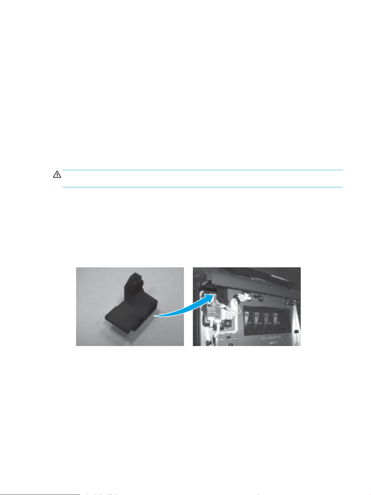
●
Ink supply door switch—used to tell the printer that the supply door is closed when the front cover is
removed.
ENWW Removal and replacement strategy 3
●
Printbar lock tool—used for holding the printbar in place.
NOTE: Rotate the tool to line up the shaft opening with the printbar shaft, and then place the tool over
the shaft to lock the printbar in place. Do not use this tool to raise or lower the printbar.
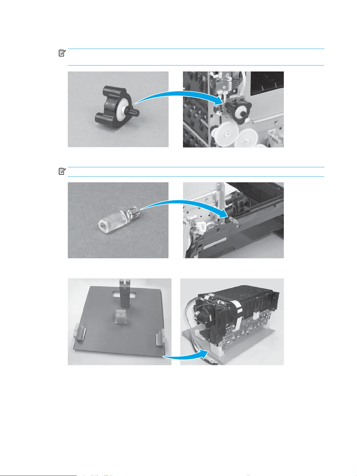
●
Service sled advance tool—used to remove and reinstall the service sled. Also raises the printbar.
NOTE: Use a one-quarter inch nut driver to remove or install the service sled.
●
Printbar dolly—used to support the printbar during removal and installation.
4 Chapter 1 Removal and replacement ENWW
●
Pick tire replacement tool—used to remove the Tray 2 pickup roller assembly.
Use this tool to release the tabs that hold the tray 2 pick-up roller in place.
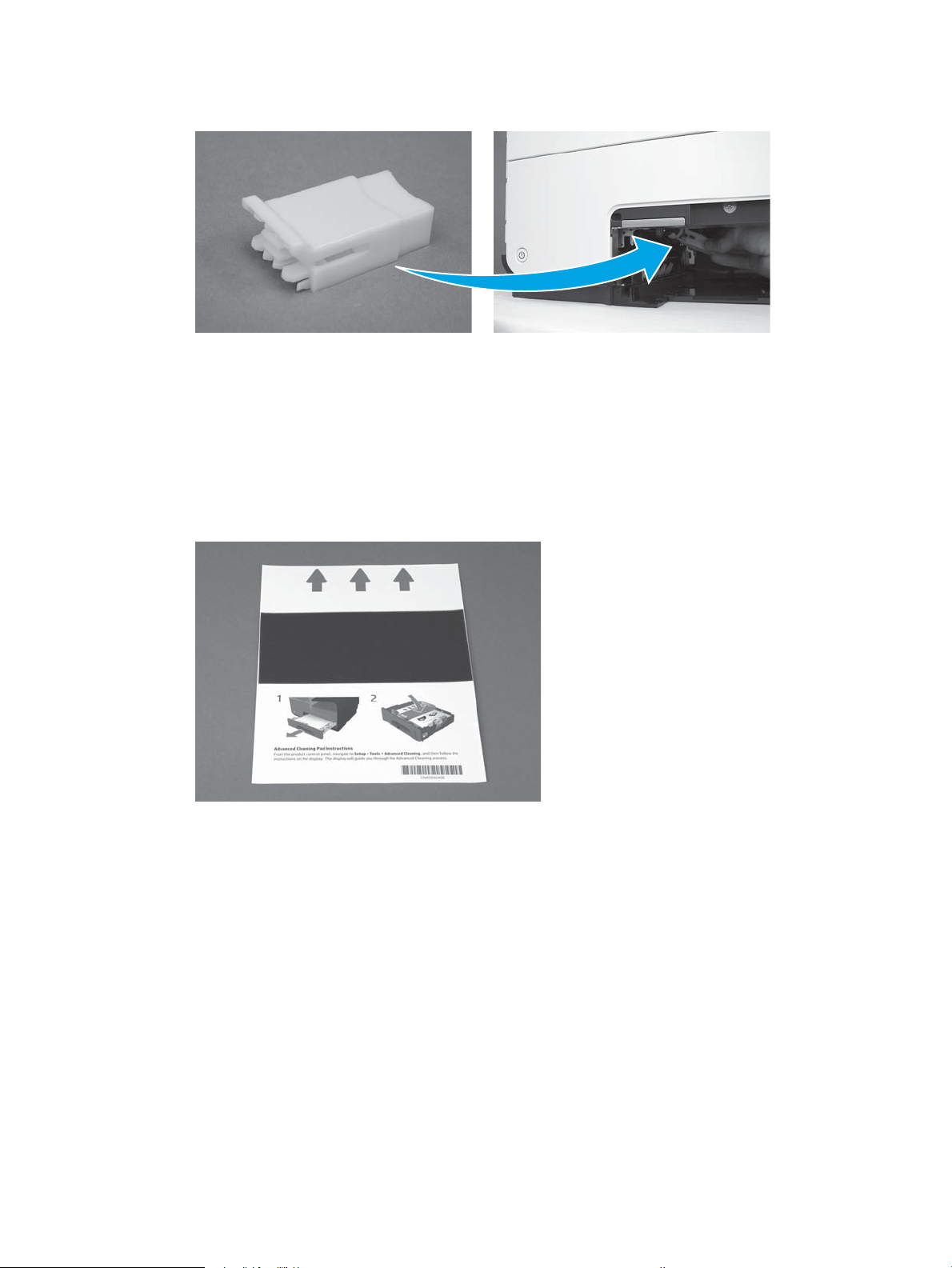
Advanced Cleaning Kit
The Advanced Cleaning Kit (part number CN459-67006) is used for resolving shim whiskers print quality
issues.
The Advanced Cleaning Kit contains the following items:
●
Sheet cleaner - full mid
●
Shim whisker kit Instructions
To use the cleaning kit, complete the following steps.
1. On the printer control panel, open the Setup
menu, and then open the following menus:
352 and 452 models
●
Tools
●
Perform Advanced Cleaning
All other models
●
Printer Maintenance
●
Perform Advanced Cleaning
ENWW Removal and replacement strategy 5
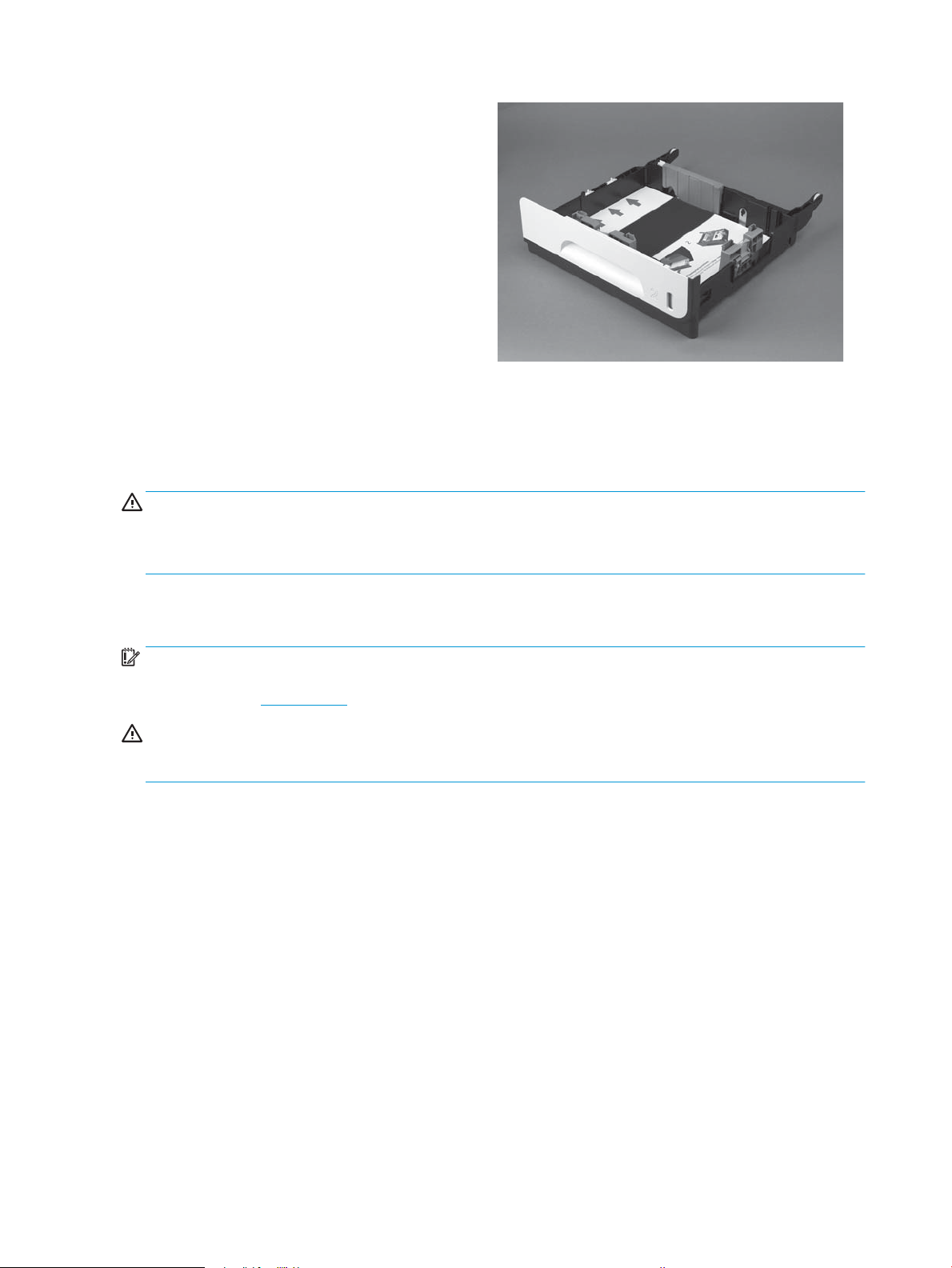
2. Open Tray 2, and then load the cleaning page face
up in the tray, with the arrows pointing to the left
side of the tray.
NOTE: The correct page orientation is shown on
the cleaning page itself.
3. Reinsert Tray 2, and then follow the instructions
on the control panel to complete the process.
Types of screws
WARNING! Make sure that assemblies are replaced with the correct screw type. Using the incorrect screw
(for example, substituting a long screw for the correct shorter screw) can cause damage to the printer or
interfere with printer operation. Do not intermix screws that are removed from one assembly with the screws
that are removed from another assembly.
Service approach
IMPORTANT: Ensure the printer has the latest rmware installed for the initial installation of the printer.
Certain repairs to this printer also require updated rmware, as noted in this document. Download rmware
for this printer at www.hp.com.
CAUTION: When working on the printer, do not pick up the unit by the scanner assembly or output tray. If
you need to move the printer while performing any service procedures, remove the scanner assembly/output
tray to reduce the weight of the printer and decrease the chances of damaging the printer.
Before performing service
●
Remove all paper from the printer.
●
Verify that the printbar is up and in the capped position.
●
Turn o the power using the power button.
●
Unplug the power cable and interface cable or cables.
●
Remove the output bin.
●
Place the printer on an ESD workstation or mat, or use an ESD strap (if one is available). If an ESD
workstation, mat, or strap is not available, ground yourself by touching the sheet-metal chassis before
touching an ESD-sensitive part.
●
Remove the Tray 2 cassette.
●
Remove the duplex module, which is located inside the left door.
6 Chapter 1 Removal and replacement ENWW

NOTE: When removing the duplex module, avoid making direct contact with the black cylinder to
prevent ink smear on skin or clothes. Keep the duplex module level to avoid spilling any maintenance
ink.
After performing service
●
Plug in the power cable.
●
Reinstall the output bin.
●
Reinstall the ink cartridges (if they were removed prior to performing service).
●
Reinstall the Tray 2 cassette.
●
Reinstall the duplex module.
●
Load paper in the printer.
Post-service test
Perform the following test to verify that the repair or replacement was successful.
Print-quality test
1. Verify that the necessary reassembly steps have been completed.
2. Make sure that the tray contains clean, unmarked paper.
3. Attach the power cord and interface cable or interface cables, and then turn on the printer.
4. Print a printer status page, network conguration page, or other test pages as specied in the part-
replacement procedures in this manual.
5. Print a print-quality page, and then verify that there are no lines, streaks, banding, or other print quality
defects.
6. Send a print job from the host computer, and then verify that the output meets expectations.
7. Clean the outside of the printer with a damp cloth.
ENWW Service approach 7
Removal and replacement procedures
1
2
3
Customer replaceable parts
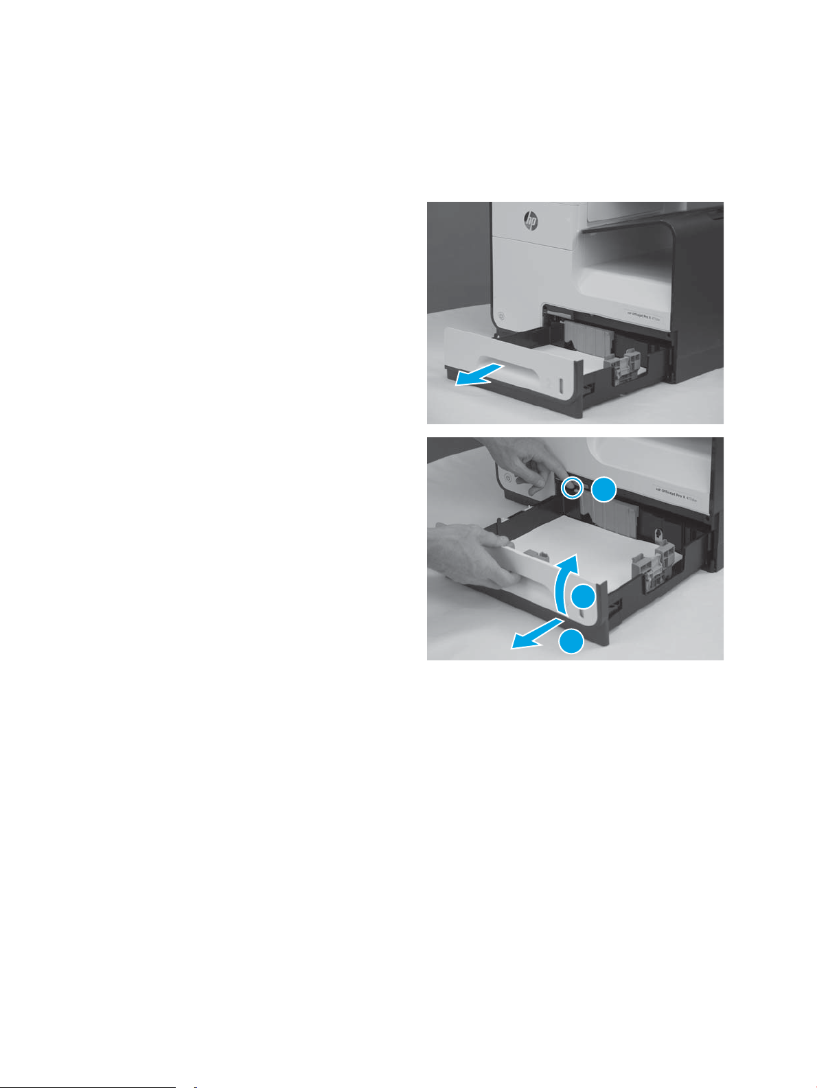
Tray 2
1. Pull out the tray.
2. Press the latch in the left-rear corner of the tray,
lift the front of the tray up, and then pull the tray
out completely.
Ink cartridges
The printer uses four colors and has a dierent ink cartridge for each color: yellow (Y), cyan (C), magenta (M),
and black (K).
8 Chapter 1 Removal and replacement ENWW
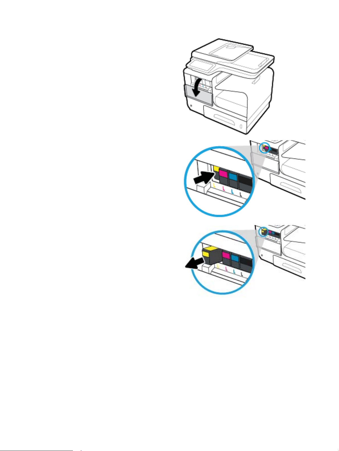
1. Open the ink cartridge access door.
2. Push the old ink cartridge inward to unlock it.
3. Grasp the edge of the old ink cartridge, and then
pull the cartridge straight out to remove it.
ENWW Removal and replacement procedures 9
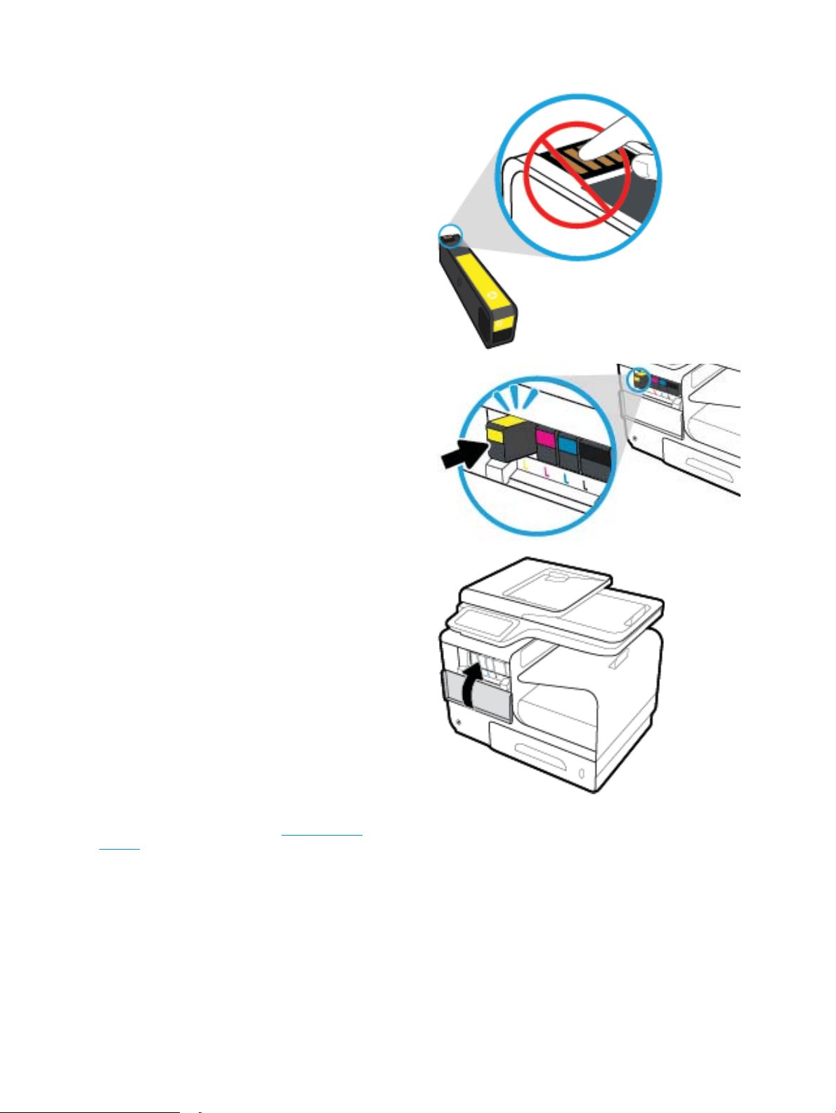
4. Remove the new ink cartridge from the
packaging. Do not touch the metal connector of
the ink cartridge. Fingerprints on the connector
can cause printer operation problems.
5. Insert the new ink cartridge into the printer. Make
sure that the metal connector on the cartridge is
facing up. If it is not installed correctly, the
cartridge will not lock in place.
6. Close the ink cartridge door.
7. Place the old ink cartridge in the box, and refer to
the HP recycling instructions at www.hp.com/
recycle.
10 Chapter 1 Removal and replacement ENWW
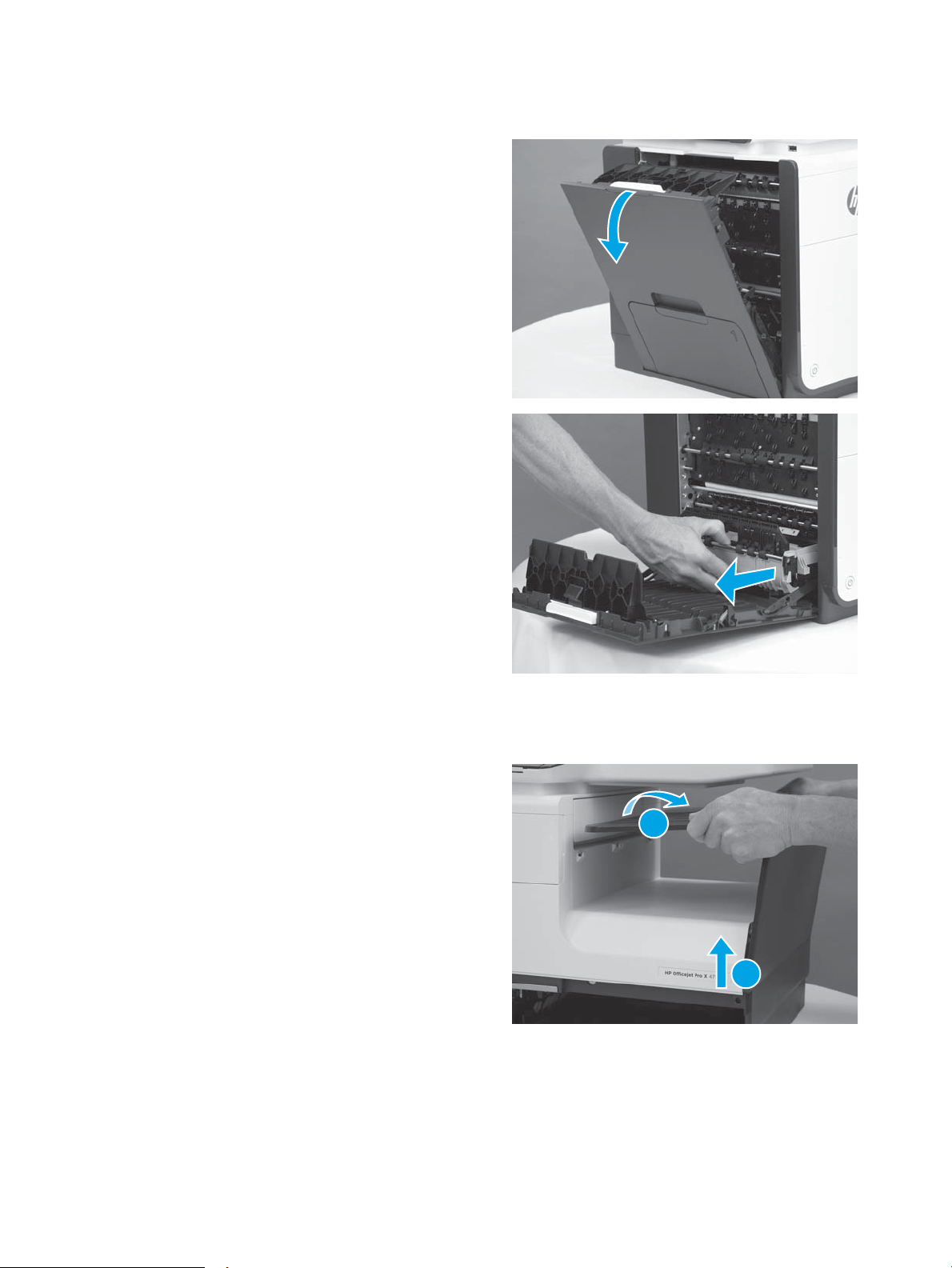
Duplex module
1
2
1. Press the latch to open the left door.
2. Grab the duplex module as shown, and then pull
it out of the printer.
NOTE: When removing the duplex module,
avoid making direct contact with the black
cylinder to prevent ink smear on skin or clothes.
Keep the duplex module level to avoid spilling
any maintenance ink.
When removing the duplex module, do not let the
bottom of the duplex module touch or rest on the
ribs on the left door, which will damage them and
might lead to paper damage and jams.
Output bin (352, 452, 377, and 477 models)
1. Detach the top of the output bin from the printer,
and then pull the bin up to remove it.
ENWW Removal and replacement procedures 11
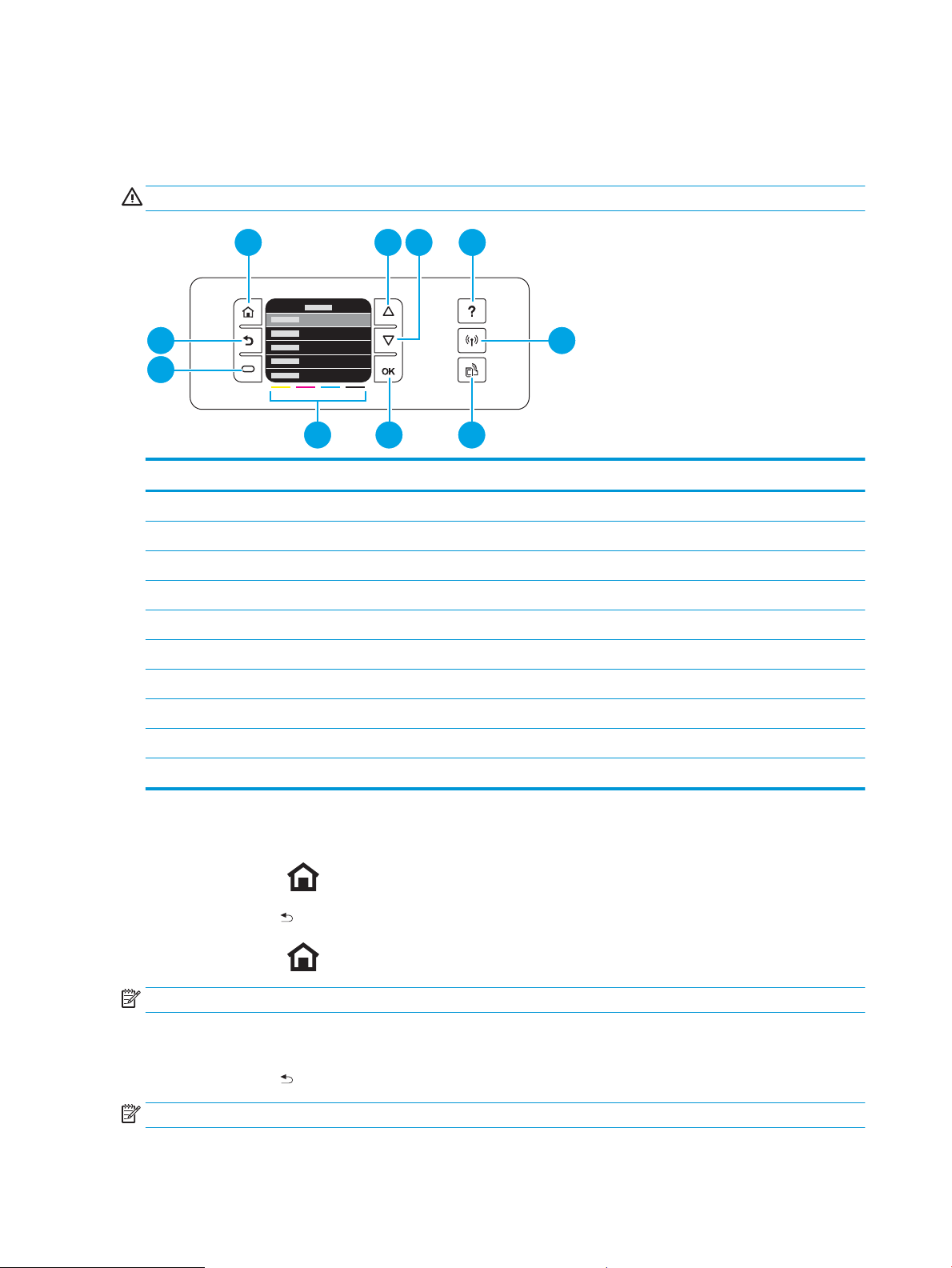
Menu access on monochrome control panels
1 2 4
8 67
9
5
3
10
These hidden engineering menus are used for testing and calibration. Some or all of them are referenced in
remove and replace sections as required.
WARNING! Misuse of these menus could damage the printer or make it unusable.
Item Description
1 Home button: Return to the power-on Home screen.
2 Up arrow button: Navigate the menus.
3 Down arrow button: Navigate the menus.
4 Help button: Open the printer help system.
5 Wireless button: Open the Wireless Setup menu.
6 HP ePrint button: Activate or deactivate the HP ePrint features.
7 OK button: Conrm the selected item.
8 Ink cartridge fuel gauges: View the estimated cartridge ink levels.
9 ATM button: Function dened by the rmware. Usually used to cancel a request.
10 Back button: Return to the previous screen.
Access the Engineering menu
1.
Press the Home button.
2. Press the Back button.
3.
Press the Home button twice to enter the Engineering menu.
NOTE: The Service menu is accessed from the Engineering menu.
Access the Support menu
▲
Press the Back button four times to enter the Support menu.
NOTE: The Support menu is usually used by HP call center agents for assisting customers.
12 Chapter 1 Removal and replacement ENWW

Place the printer into MFG (manufacturing) mode
NOTE: This mode is to be used only by authorized service providers. It should never be accessed by the end
user.
1. Press and hold the Up and Down buttons together while plugging in the printer until the control-
panel displays MFG mode.
2. Press the power button to enter MFG (on) mode.
ENWW Removal and replacement procedures 13
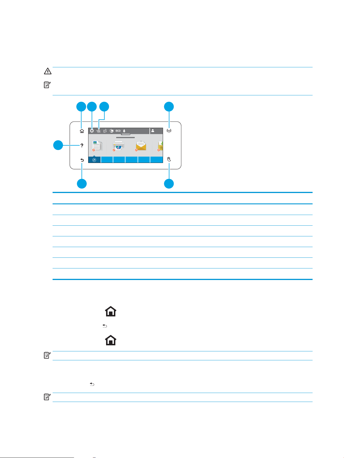
Menu access on color control panels
1 2 4
6 5
7
3
These hidden engineering menus are used for testing and calibration. Some or all of them are referenced in
remove and replace sections as required.
WARNING! Misuse of these menus could damage the printer or make it unusable.
NOTE: These buttons are not illuminated until they are touched with suicient pressure. Locate these
buttons by sweeping your nger over the general areas.
Item Description
1 Home button: Return to the power-on Home screen.
2 Setup button: Open the Setup menu.
3 Network button: Open the Network Setup menu.
4 Wireless button: Open the Wireless Setup menu.
5 NFC button: Connect to the printer via the near eld communication (NFC) protocol.
6 Back button: Return to the previous screen.
7 Help button: Open the printer help system.
Access the Engineering menu
1.
Touch the Home button.
2. Touch the Back button.
3.
Touch the Home button twice to enter the Engineering menu.
NOTE: The Service menu is accessed from the Engineering menu.
Access the Support Menu
Touch the Back button four times consecutively to open the Support Menu.
NOTE: The Support Menu is usually used by HP call center agents for assisting customers.
14 Chapter 1 Removal and replacement ENWW

Place the printer into MFG (manufacturing) mode
NOTE: These two modes are ONLY to be used by authorized service providers. They should NEVER be
accessed by the end user.
1. Press and hold the power button while plugging in the printer. The HP logo appears on the printer
control panel, and then disappears. Continue to hold the power button for ve seconds after the logo
disappears.
2. Release the power button.
3.
Touch the Home button.
4. Touch the Back button.
5.
Touch the Home button twice.
6.
After a new screen appears, touch the Home button again to enter MFG (o) mode.
7. Press the power button to enter MFG (on) mode.
ENWW Removal and replacement procedures 15

Perform tap tests and interpret results
Perform a tap test
1. Open the Engineering Menu. See Menu access on monochrome control panels on page 12 or Menu
access on color control panels on page 14.
2. Open the Manufacturing Menu.
3. Open the Reports Menu.
4. Open the Print-mech tap tests menu.
5. Select the tap test to run.
10 tap test results (OOBE states)
The printed tap test results contain a sequence of numbers at line number 68, "Startup Complete," of the
printed report.
Use the following table to interpret these numbers.
Table 1-1 10 tap test results, row 69
Column Code Acceptable values
Column 1 DSID_PEN_PRINTER_STARTUP_BITS A value of 1 indicates that the printbar has been started up. This
means that shipping uid has been removed from the printbar and
replaced with ink. This is the expected state for a printer after
initialization.
Column 2 DSID_OOBE_STATE 255–OOBE messaging complete.
Column 3 DSID_INK_SUPPLY_OOBE_COMPELTE 1–SHF purge is complete and service wipes have been enabled.
Column 4 DSID_CAL_OOBE_STATE A value of 2 means that the OOBE printed calibrations are
complete.
A value of 1 means the OOBE printed calibrations are in progress
A value of 0 means the OOBE printed calibration does not exist so
no printing/calibration for OOBE is attempted.
Column 5 DSID_IQ_LIST_INDEX A value of 3 means that pen height and beam center have been
completed, and that BDD is scheduled (or pending) to perform
normally.
16 Chapter 1 Removal and replacement ENWW
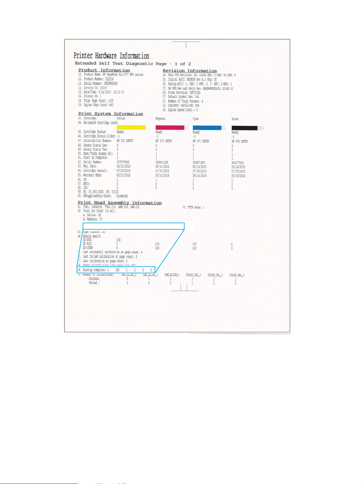
69. Startup complete: 1 255 1 2 0
ENWW Removal and replacement procedures 17

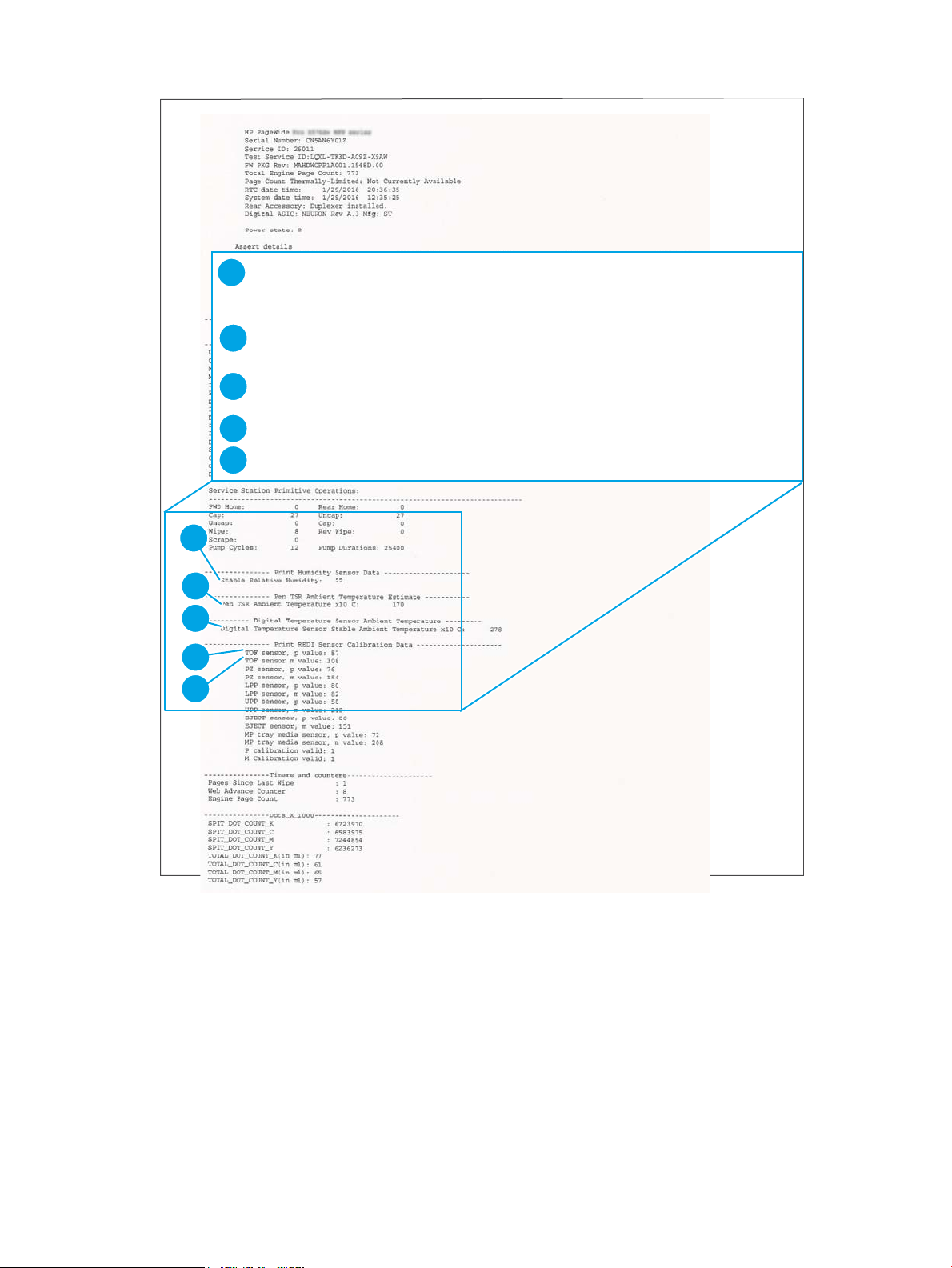
12 tap test results (REDI sensor values)
Table 1-2 12 tap test report
Callout Report area Item Acceptable values
1 Print Humidity Sensor Data Stable Relative Humidity 0–100 RH
2 Pen TSR Ambient Temperature
Estimate
3 Digital Temperature Sensor Ambient
Temperature
4 Print REDI Sensor Calibration Data
5 Print REDI Sensor Calibration Data
1
“M” is mirror result, “P” is blocked with paper.
Pen TSR Ambient Temperature x10 °C ± 10 °C of current ambient
temperature
Digital Temperature Sensor Ambient
Temperature x10 °C
TOF sensor, p value
TOF sensor, m value
1
1
± 10 °C of current ambient
temperature
Between 10 and 100
Between 25 and 380
18 Chapter 1 Removal and replacement ENWW
5
1
2
3
4
Stable Relative Humidity: 22
----------------Print TSR Ambient Temperature Estimate-------------Pen TSR Ambient Temperature x10C: 170
----------Digital Temperature Sensor Ambient Temperature--------Digital Temperature Sensor Ambient Temperature x10 C: 278
----------------Print REDI Sensor Calibration Data---------------------TOF sensor, p value: 57
TOF sensor m value: 308
5
1
2
3
4
ENWW Removal and replacement procedures 19
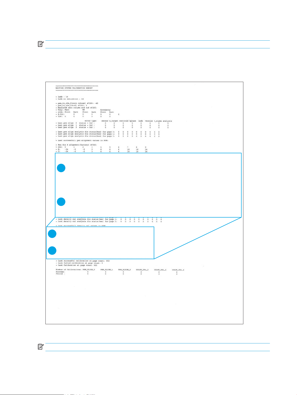
61 tap results (Align and color calibrations)
= Color scale (factory) :
= dia: 0 1 2 3 4 5 6 7 8 9
= K: 0x7eec 0x7f3c 0x8265 0x8280 0x8215 0x8070 0x7fcf 0x804b 0x7cea 0x7d65
= C: 0x7d51 0x7fbo 0x8063 0x81b5 0x80c5 0x81a1 0x7fc5 0x80ed 0x7dea 0x7fe6
= M: 0x7d51 0x7fbo 0x8063 0x81b5 0x80c5 0x81a1 0x7fc5 0x80ed 0x7dea 0x7fe6
= Y: 0x7d51 0x7fbo 0x8063 0x81b5 0x80c5 0x81a1 0x7fc5 0x80ed 0x7dea 0x7fe6
= Color scale (current) :
= dia: 0 1 2 3 4 5 6 7 8 9
= K: 0x7eec 0x7f3c 0x8265 0x8280 0x8215 0x8070 0x7fcf 0x804b 0x7cea 0x7d65
= C: 0x7d51 0x7fbo 0x8063 0x81b5 0x80c5 0x81a1 0x7fc5 0x80ed 0x7dea 0x7fe6
= M: 0x7d51 0x7fbo 0x8063 0x81b5 0x80c5 0x81a1 0x7fc5 0x80ed 0x7dea 0x7fe6
= Y: 0x7d51 0x7fbo 0x8063 0x81b5 0x80c5 0x81a1 0x7fc5 0x80ed 0x7dea 0x7fe6
1
2
= K: 0x7eec 0x7f3c 0x8265 0x8280 0x8215 0x8070 0x7fcf 0x804b 0x7cea 0x7d65
= C: 0x7d51 0x7fbo 0x8063 0x81b5 0x80c5 0x81a1 0x7fc5 0x80ed 0x7dea 0x7fe6
= M: 0x7d51 0x7fbo 0x8063 0x81b5 0x80c5 0x81a1 0x7fc5 0x80ed 0x7dea 0x7fe6
= Y: 0x7d51 0x7fbo 0x8063 0x81b5 0x80c5 0x81a1 0x7fc5 0x80ed 0x7dea 0x7fe6
= Color scale (factory):
= dia: 0 4 5 6 8 97312
= K: 0x7eec 0x7f3c 0x8265 0x8280 0x8215 0x8070 0x7fcf 0x804b 0x7cea 0x7d65
= C: 0x7d51 0x7fbo 0x8063 0x81b5 0x80c5 0x81a1 0x7fc5 0x80ed 0x7dea 0x7fe6
= M: 0x7d51 0x7fbo 0x8063 0x81b5 0x80c5 0x81a1 0x7fc5 0x80ed 0x7dea 0x7fe6
= Y: 0x7d51 0x7fbo 0x8063 0x81b5 0x80c5 0x81a1 0x7fc5 0x80ed 0x7dea 0x7fe6
= Color scale (current):
= dia: 0 4 5 6 8 97312
1
2
NOTE: If you hold the up or down arrows down, the tap count will start incrementing by 10, or 100
An acceptable 61 tap test has identical values for the parameters in the “Color scale (factory)” (1) and “Color
scale (current)” (2) on the printed report areas. “Color scale (factory)” and “Color scale (current)” will be
identical after a main PCA replacement, but may not be the same under other conditions. The values should
also be identical after a printbar replacement.
909 tap test results (BDD status)
NOTE: If you hold the up or down arrows down, the tap count will start incrementing by 10, or 100
20 Chapter 1 Removal and replacement ENWW
 Loading...