

Page 1

Service Gu ide
Publication Number 34970-90012 (order as 34970-90101 manual set)
Edition 3, March 2003
© Copyright Agilent Technologies, Inc. 1997-2003
For Safety information, Warranties, and Regulatory information,
see the pages following the Index.
Note: The schematics for the 34970A are available as a separate
downloadable PDF file from the Agilent web site at www.agilent. com.
Agilent 34970A
Data Acquistion / S witch Unit
Page 2

Page 3

Note: Unless otherwise indicated, this manual applies to all serial numbers.
The Agilent Technologies 34970A combines precision measurement
capability with flexible signal connections for your production and
development test systems. Three module slots are built into the rear
of the instrument to accept any combination of data acquisition or
switching modules. The combination of data logging and data
acquisition features makes this instrument a versatile solution for your
testing requirements now and in the future.
Convenient Data Logging Features
• Direct measurement of thermocouples, RTDs, thermistors, dc voltage,
ac voltage, resistance, dc current, ac current, frequency, and period
• Interval scanning with storage of up to 50,000 time-stamped readings
• Independent channel configuration with function, Mx+B scaling,
and alarm limits available on a per-channel basis
• Intuitive user interface with knob for quick channel selection,
menu navigation, and data entry from the front panel
• Portable, ruggedized case with non-skid feet
• BenchLink Data Logger Software for Microsoft
®
Windows
®
included
Warning
Flexible Data Acquisition / Sw itching Features
1
• 6
⁄
-digit multimeter accuracy, stability, and noise rejection
2
• Up to 60 channels per instrument (120 single-ended channels)
• Reading rates up to 600 readings per second on a single channel and
scan rates up to 250 channels per second
• Choice of multiplexing, matrix, general-purpose Form C switching,
RF switching, digital I/O, totalize, and 16-bit analog output functions
• GPIB (IEEE-488) interface and RS-232 interface are standard
• SCPI (Standard Commands for Programmable Instruments) compatib ility
The procedures in this manual are intended for use by qualified,
service-trained personnel only.
Agilent 34970A
Data Acquisition / S witch Unit
Page 4
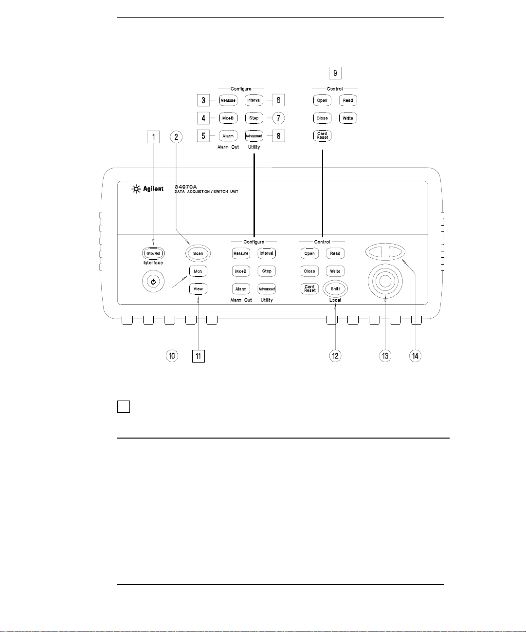
The Front Panel at a Glance
Denotes a menu key. S e e th e n ex t p a g e f or d et a il s on me nu o pe ra tio n .
1 State Storage / Remote Interface Menus
2 Scan Start / Stop Key
3 Measurement Configuration Menu
4 Scaling Configuration Menu
5 Alarm / Alarm Output Configuration Menu
6 Scan-to-Scan Interval Menu
7 Scan List Single Step/Read Key
8 Advanced Measurement / Utility Menus
9 Low-Level Module Contr ol Keys
10 Single-Channel Monitor On/Off Key
11 View Scanned Data, Alarms, Errors Menu
12 Shift / Local Key
13 Knob
14 Navigation Arrow Keys
2
Page 5
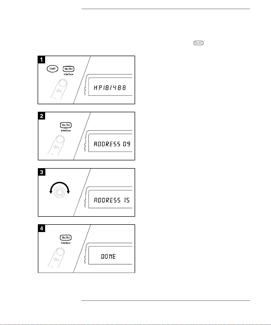
The Front-Panel Menus at a Glance
Several of the front-panel keys guide you through menus to configure
various parameters of the instrument (see previous page). The following
steps demonstrate the menu structure using the key.
1 Press the menu key. You are automatically
guided to the first level of the menu.
Rotate the knob to view the other choices
on the first level of the menu.
The menu will automatically timeout after
about 20 seconds of inactivity. You will be
returned to the operation in progress prior
to entering the menu.
2 Press the same menu key again to move
to the next item of the menu. Typically,
this is where you choose parameter values
for the selected operation.
3 Rotate the knob to view the choices on this
level of the menu. When you reach the end
of the list, rotate the knob in the opposite
direction to view all of the other choices.
The current selection is highlighted for emphasis.
All other choices are dimmed.
4 Press the same menu key again to accept the
change and exit the menu. A brief confirmation
message is displayed.
Tip: To review the current configuration of a specific menu, press the menu key several times.
A message
NO CHANGES is displayed when you exit the menu.
3
Page 6
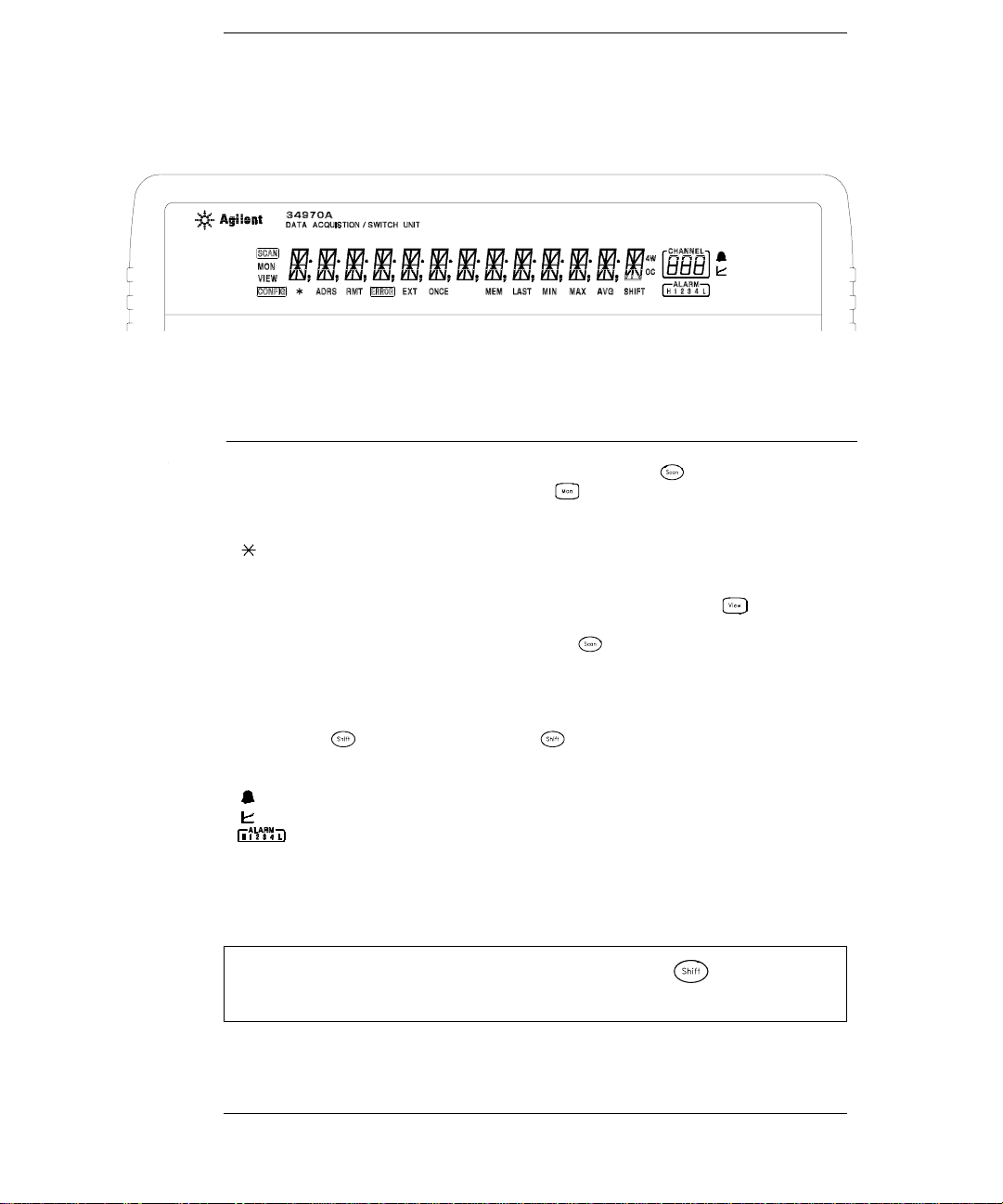
Display Annunciators
SCAN
MON
VIEW
CONFIG
ADRS
RMT
ERROR
EXT
ONCE
MEM
LAST
MIN
MAX
SHIFT
4W
OC
Scan is in progress or enabled. Press and hold again to t urn of f .
Monitor mode is enabled. Press again to turn off.
Scanned readings, alarms, errors, or relay cycles are being viewed.
Channel configuration is in progress on displayed channel.
Measurement is in progress.
Instrument is addressed to listen or talk over the remote interface.
Instrument is in remote mode (remote interface).
Hardware or remote interface errors are detected. Press to read err o r s .
Instrument is configured for an external scan interval.
Scan Once mode is enabled. Press t o initiat e and hold key to disable.
Reading memory overflow; new readings will overwrite the oldest readings.
Viewed data is the last reading stored during most recent scan.
Viewed data is the minimum reading stored during most recent scan.
Viewed data is the maximum reading stored during most recent scan.
has been pressed. Press again to turn off.
4-wire function is in use on displayed channel.
Offset compensation is enabled on displayed channel.
Alarms are enabled on displayed channel.
Mx+B scaling is enabled on displayed channel.
HI or LO alarm condition has occurred on indicated alarms.
To review the display annunciators, hold down the key as you
turn on the instrument.
4
Page 7
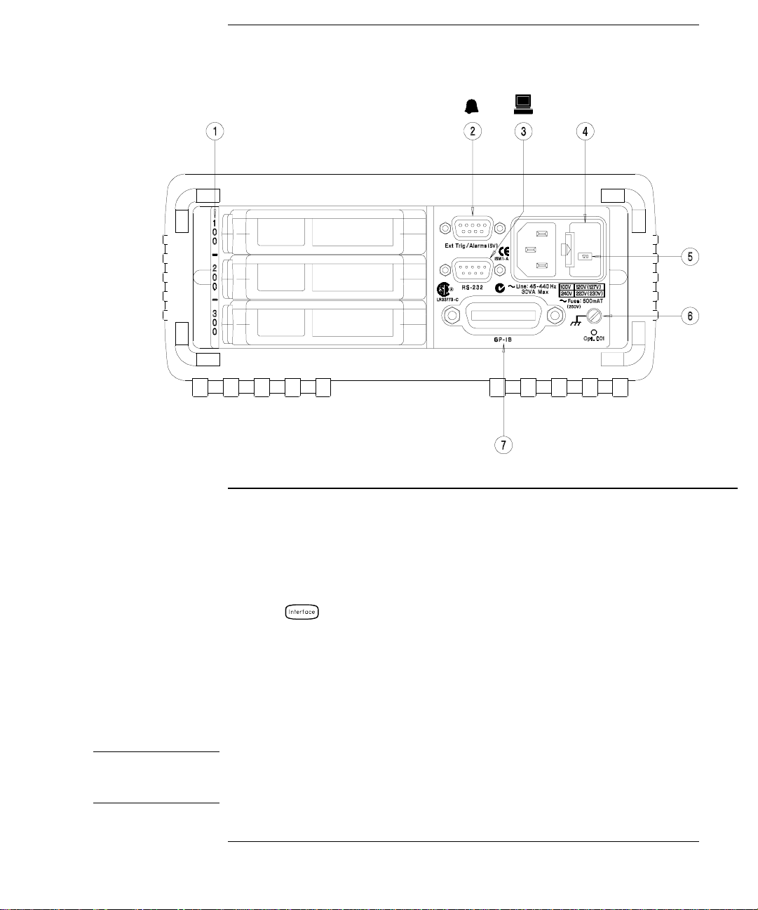
The Rear Panel at a Glance
WARNING
1 Slot Identifier (100, 200, 300)
2 Ext Trig Input / Alarm Outputs / Channel
Advance Input / Channel Closed Output
(for pinouts, see chapter 4 in User’s Guide)
3 RS-232 Interface Connector
Use the Menu to:
• Select the GPIB or RS-232 interface (see chapter 2 in User’s Guide).
• Set the GPIB address (see chapter 2 in User’s Guide).
• Set the RS-232 baud rate, parity, and flow control mode (see chapter 2 in User’s Guide).
4 Power-Line Fuse-Holder Assembly
5 Power-Line Voltage Setting
6 Chassis Ground
7 GPIB (IEEE-488) Interface Connector
For protection from electrical shock, the power cord ground must not be
defeated. If only a two-contact electrical outlet is available, connect the
instrument’s chassis ground screw (see above) to a good earth ground.
5
Page 8
The Plug-In Modules at a Glance
For complete specifications on each plug-in module, refer to the module
sections in chapter 1.
34901A 20-Channel Armature Multiplexer
• 20 channels of 300 V switching
• Two channels for DC or AC current measurements (100 nA to 1 A)
• Built-in ther mocouple reference junction
• Switching speed of up to 60 channels per second
• Connects to the internal multimeter
Each of the 20 channels switches both
fully isolated inputs to the internal multimeter. The module is divided
into two banks of 10 two-wire channels each. When making four-wire
resistance measurements, channels from Bank A are automatically
paired with channels from Bank B. Two additional fused channels are
included on the module (22 channels total) for making calibrated
AC current measurements with the internal multimeter (external shunt
resistors are not required). You can close multiple channels on this
module only if you have not configured any channels to be part of the scan
list. Otherwise, all channels on the module are break-before-make.
HI and LO inputs, thus providing
DC or
34902A 16-Channel Reed Multiplexer
• 16 channels of 300 V switching
• Built-in ther mocouple reference junction
• Switching speed of up to 250 channels per second
• Connects to the internal multimeter
Use this module for high-speed scanning and high-throughput
automated test applications. Each of the 16 channels switches both
HI and LO inputs, thus providing fully isolated inputs to the internal
multimeter. The module is divided into two banks of eight two-wire
channels each. When making four-wire resistance measurements,
channels from Bank A are automatically paired with channels from
Bank B. You can close multiple channels on this module only if you have
not configured any channels to be part of the scan list. Other wise, al l
channels on the module are break-before-make.
6
Page 9
34903A 20-Channel Actuator / G eneral-Purpose Switch
• 300 V, 2 A actuation and switching
• SPDT (Form C) latching relays
• Breadboard area for custom circuits
Use this module for those applications that require high-integrity
contacts or quality connections of non-multiplexed signals. This module
can switch 300 V, 1 A (50 W maximum switch power) to your device
under test or to actuate external devices. Screw terminals on the module
provide access to the Normally-Open, Normally-Closed, and Common
contacts for each of the 20 switches. A breadboard area is provided near
the screw terminals to implement custom circuitry, such as simple
filters, snubbers, or voltage dividers.
34904A 4x8 Two-Wire Matrix Switch
• 32 two-wire crosspoint s
• Any combination of inputs and outputs can be connected at a time
• 300 V, 1 A switching
Use this module to connect multiple instruments to multiple points on
your device under test at the same time. You can connect rows and
columns between multiple modules to build larger matrices such as
8x8 and 4x16, with up to 96 crosspoints in a single mainframe.
34905/6A Dual 4-Channel RF Multiplexers
• 34905A (50Ω ) / 34906A (75Ω )
• 2 GHz bandwidth with on-board SMB connections
• 1 GHz bandwidth with SMB-to-BNC adapter cables provided
These modules offer wideband switching capabilities for high frequency
and pulsed signals. Each module is organized in two independent banks
of 4-to-1 multiplexers. Both modules offer low crosstalk and excellent
insertion loss performance. To create larger
cascade multiple banks together. Only one channel in each bank may be
closed at a time.
RF multiplexers, you can
7
Page 10

34907A Multifunction Module
• Two 8-bit Digital Input/Output ports, 400 mA sink, 42 V open collector
• 100 kHz Totalize input with 28 bits of resolution
• Two 16-bit, ± 12 V Calibrated Analog Outputs
Use this module to sense status and control external devices such as
solenoids, power relays, and microwave switches. For greater flexibility,
you can read digital inputs and the count on the totalizer during a scan.
34908A 40-Channel Single-Ended Multiplexer
• 40 channels of 300 V single-ended (common LO) switching
• Built-in thermocouple isothermal reference junction
• Switching speed of up to 60 channels per second
• Connects to the internal multimeter
Use this module for high-density switching applications which require
single-wire inputs with a common
to ensure that only one relay is connected at any time.
LO. All relays are break-before-make
8
Page 11

In This Book
Specifications Chapter 1 lists the technical specifications for the
mainframe and plug-in modules.
Quick Start Chapter 2 helps you get familiar with a few of the
instrument’s front-panel features.
Front-Panel Overview Chapter 3 introduces you to the front-panel
menus and describes some of the instrument’s menu features.
Calibration Procedures Chapter 4 provides calibration, verification,
and adjustment procedures for the instrument.
Theory of Operation Chapter 5 describes block and circuit level
theory related to the operation the instrument.
Service Chapter 6 provides guidelines for returning your instrument
to Agilent Technologies for servicing, or for servicing it yourself.
Replaceable Parts Chapter 7 contains detailed parts lists for the
mainframe and plug-in modules.
Schematics Chapter 8 contains the instrument’s block diagram,
schematics, disassembly drawings, and component locator drawings.
If you have questions relating to the operation of the 34970A,
call 1-800-452-4844 in the United States, or contact your nearest
Agilent Technologies Sales Office.
If your 34970A fails within three years of original purchase, Agilent will
repair or replace it free of charge. Call 1-877-447-7278 and ask for
“Express Exchange.”
9
Page 12

Contents
Contents
Chapter 1 Specifications
DC, Resistance, and Temperature Accuracy Specifications 16
DC Measurement and Operating Characteristics 17
AC Accuracy Specifications 18
AC Measurement and Operating Characteristics 19
Measurement Rate s an d Sys t em Char a c ter i sti c s 20
Module Specifications 21
BenchLink Data Logger Soft ware Specifications 24
Product and Module Dimensions 25
To Calculate Total Measurement Error 26
Interpreting Internal DMM Specifications 28
Configuring for Highest Accuracy Measurements 31
Chapter 2 Quick Start
To Prepare the Instrument for Use 35
To Connect Wiring to a Module 36
To Set the Time and Date 38
To Configure a Measurement Channel 39
To Monitor a Single Ch an ne l 40
To Close a Channel 41
If the Instrument Does Not Turn On 42
To Adjust the Carrying Handle 44
To Rack Mount the Instrument 45
Chapter 3 Front-Panel Overview
Front-Panel Menu Reference 49
To Unsecure for Calibration 51
To Secure Against Cali br a tio n 51
To Change the Security Code 52
Error Messages 52
To Perform a Zero Adjustment 53
To Apply Mx+B Scaling to Measurements 54
To Read the Relay Cycle Count 55
To Read a Digital Input Port 56
To Write to a Digital Output Port 57
To Read the Totalizer Count 58
To Output a DC Voltage 59
10
Page 13

Contents
Chapter 4 Calibration Procedures
Agilent Technologies Calibration Services 63
Calibration Interval 63
Adjustment is Recommended 63
Time Required for Calibration 64
Automating Calibration Procedures 64
Recommended Test Equipment 65
Input Connections 66
Calibration Security 67
To Unsecure the Instrument Without the Security Code 68
Calibration Message 69
Calibration C o unt 69
Calibration Pr ocedure 70
Aborting a Calibration in Progress 70
Test Considerations 71
Performance Verification Tests 72
Self-Test 73
Quick Performanc e Check 74
Performance Verification Tests 74
Internal DMM Verification Tests 75
Zero Offset Verification 75
Gain Verification 77
Optional AC Performance Verification Tests 80
Internal DMM Adj ustments 81
Zero Adjustment 81
Gain Adjustment 82
–10 Vdc Adjustment Pro cedure (Optional) 85
Plug-in Mo dule Test Consideration s 87
Relay Verification 88
Relay Cycle Count 88
34901A Relay Contact Resistan ce V eri fication (Optional) 89
34902A Relay Contact Resistan ce V eri fication (Optional) 96
34903A Relay Contact Resistan ce V eri fication (Optional) 101
34904A Relay Contact Resistan ce V eri fication (Optional) 102
34905A/06A Relay Contact Resistance Verification (Optional) 105
34908A Relay Contact Resistan ce V eri fication (Optional) 106
Thermocouple Reference Junction (Optional) 112
Thermocouple Reference Junction Verificati on 112
Thermocouple Reference Junction Adjustments 113
34907A Analog Ou tput 114
Analog Output Verification Test 114
Analog Output Adjustment 115
Contents
11
Page 14

Contents
Contents
Chapter 5 Theory of Operation
System Block Diagram 119
Floating Logic 120
Memory 123
Earth-Referenced Logic 124
Power Supplies 125
Front Panel 127
Backplane 128
Analog Bus 128
Digital Bus 128
Internal DMM 129
DMM Block Diagram 129
Input 130
Input Amplifier 131
Ohms Current Source 133
AC Circuit 134
A-to-D Converter 136
Switch Modules 138
Switch Module Control 138
Relay Drivers 140
34901A 142
34902A 144
34903A 146
34904A 147
34905A/34906A 148
34908A 149
Multifunction Mo d ul e 151
Multifunction Control 151
Totalizer 153
Analog Output 154
Digital I/O 155
Chapter 6 Service
Operating Checklist 159
Is the instrument inope rat i v e? 159
Does the instrument fail self-test? 159
Is the Current measurement function inoperative? 159
Types of Service Available 160
Standard Repair Service (worldwide) 160
Express Exchange (U.S.A. only) 160
Repackaging for Shipment 161
Cleaning 161
Electrostatic Discharge (ESD) Precautions 162
Surface Mount Repair 162
To Replace the Power-Line Fuse 163
12
Page 15

Contents
Chapter 6 Service (continued)
Troubleshoot i ng Hi nt s 163
Unit is Inoperative 163
Unit Reports Error 705 164
Isolating to an Assembly 164
Unit Fails Self-Test 164
Power Supplies 165
Self-Test Procedures 167
Power-On Self-Test 167
Complete Self-Test 167
Plug-in Module Self-Test 167
Self-Tests 168
Battery Check and Replacement 172
To Verify the Battery 173
To Replace the Battery 173
Disassembly 174
General Disassembly 175
Internal DMM Disassembly 176
Front-Panel Chassis Disassembly 177
Additional Disassembly 178
Plug-in Module Disassembly 179
Chapter 7 Replaceable Parts
Replaceable Parts 182
To Order Replaceable Parts 182
34970A Mainframe 183
34970-66501 Main PC Assembly (A1) 184
34970-66502 Front-Panel and Keyboard PC Asse mb ly (A2) 189
34970-66503 Backplane PC Assemb ly (A 3) 190
34970-66504 Internal DMM PC Assembly (A4) 191
34901A 20-Channel Multiplexer 196
34902A 16-Channel Multiplexer 200
34903A 20-Channel Actuator 202
34904A 4x8 Matrix 204
34905A/34906A RF Multiplexer 207
34907A Multifunction Modul e 209
34908A 40-Channel Multiplexer 213
Manufacturer’s List 216
Contents
13
Page 16

Contents
Contents
Chapter 8 Schematics
Agilent 34970A System Block Diagram 221
A1 Component Locator (top) 222
A1 Component Locator (bottom) 223
A1 Power Supply Schematic (Sheet 1 of 4) 224
A1 Floating Logic Schematic (Sheet 2 of 4) 225
A1 Earth Referenced Logic Schematic (Sheet 3 of 4) 226
A1 Memory Schematic (Sheet 4 of 4) 227
A2 Component Locator 228
A2 Display and Keyboard Schematic 229
A3 Component Locator 230
A3 Backplane Schematic 231
A4 Component Locator (top) 232
A4 Component Locator (bottom) 233
A4 Input and Protection Schematic (Sheet 1 of 4) 234
A4 Input Amplifier and Ohms Cu rr en t Sch em ati c (Sheet 2 of 4) 235
A4 AC Schematic (Sheet 3 of 4) 236
A4 A/D Converter Schematic (Sheet 4 of 4) 237
34901A 20-Channel M ul tipl exe r Compo ne nt Loc a t or 238
34901A 20-Channel Multiplexer Schematic (Sheet 1 of 5) 239
34901A 20-Channel Multiplexer Schematic (Sheet 2 of 5) 240
34901A 20-Channel Multiplexer Schematic (Sheet 3 of 5) 241
34901A 20-Channel Multiplexer Schematic (Sheet 4 of 5) 242
34901A 20-Channel Multiplexer Schematic (Sheet 5 of 5) 243
34902A 16-Channel M ul tipl exe r Compo ne nt Loc a t or 244
34902A 16-Channel Multiplexer Schematic (Sheet 1 of 4) 245
34902A 16-Channel Multiplexer Schematic (Sheet 2 of 4) 246
34902A 16-Channel Multiplexer Schematic (Sheet 3 of 4) 247
34902A 16-Channel Multiplexer Schematic (Sheet 4 of 4) 248
34903A 20-Chann el Actu at o r Compo ne nt Locator 249
34903A 20-Channel Actuator Schematic (Sheet 1 of 3) 250
34903A 20-Channel Actuator Schematic (Sheet 2 of 3) 251
34903A 20-Channel Actuator Schematic (Sheet 3 of 3) 252
34904A 4x8 Matri x Compo ne nt Loc a tor 253
34904A 4x8 Matrix Schematic (Sheet 1 of 3) 254
34904A 4x8 Matrix Schematic (Sheet 2 of 3) 255
34904A 4x8 Matrix Schematic (Sheet 3 of 3) 256
34905A/34906A R F Mul t ipl exe r Co mpone nt Loc a tor 257
34905A/34906A RF Multiplexer Schematic (Sheet 1 of 2) 258
34905A/34906A RF Multiplexer Schematic (Sheet 2 of 2) 259
34907A Multifun c tio n Mo dul e Com p on en t Locato r 260
34907A Multifunction Modul e Sc hema t ic (S he et 1 of 5) 261
34907A Multifunction Modul e Sc hema t ic (S he et 2 of 5) 262
34907A Multifunction Modul e Sc hema t ic (S he et 3 of 5) 263
34907A Multifunction Modul e Sc hema t ic (S he et 4 of 5) 264
34907A Multifunction Modul e Sc hema t ic (S he et 5 of 5) 265
34908A 40-Channel M ul tipl exe r Compo ne nt Loc a t or 266
34908A 40-Channel Multiplexer Schematic (Sheet 1 of 3) 267
34908A 40-Channel Multiplexer Schematic (Sheet 2 of 3) 268
34908A 40-Channel Multiplexer Schematic (Sheet 3 of 3) 269
14
Page 17

1
• DC, Resistance, and Temperature Accuracy Specifications, on page 16
• DC Measurement and Operating Characteristics, on page 17
• AC Accuracy Specifications, on page 18
• AC Measurement and Operating Characteristics, on page 19
• Measurement Rates and System Characteristics, on page 20
• Module Specifications:
34901A, 34902A, 34908A, 34903A, 34904A, on page 21
34905A, 34906A, on page 22
Typical AC Performance Graphs, on page 23
34907A, on page 24
• BenchLink Data Logger Software Specifications, on page 24
• Product and Module Dimensions, on page 25
• To Calculate Total Measurement Error, on page 26
• Interpreting Multimeter Specifications, on page 28
• Configuring for Highest Accuracy Measurements, on page 31
1
Specifications
Page 18
Chapter 1 Specifications
DC, Resistance, and Temperature Accuracy Specifications
DC, Resistance, and Temperature Accura cy Specifications
± ( % of reading + % of range )
[1]
Includes measurement error, switching error, and transducer conversion error
Function Range
[3]
Test Current or
Burden Voltage
DC Voltage 100.0000 mV
1.000000 V
10.00000 V
100.0000 V
300.000 V
Resistance
DC Current
34901A Only
Temperature
Thermocouple
RTD R
[4]
[6]
100.0000 Ω
1.000000 kΩ
10.00000 kΩ
100.0000 kΩ
1.000000 MΩ
10.00000 MΩ
100.0000 MΩ
10.00000 mA
100.0000 mA
1.000000 A
Type
B
E
J
K
N
R
S
T
from 49Ω
0
to 2.1 kΩ
1 mA current source
1 mA
100
10
µA
µA
5
500 nA
500 nA || 10 M
< 0.1 V burden
< 0.6 V
< 2 V
1100
-150
-150
-100
-100
300
400
-100
-200°C to 600°C 0.06°C0.003°C
Thermistor 2.2 k, 5 k, 10 k -80
µA
Ω
Best Range Accuracy
°C to 1820°C
°C to 1000°C
°C to 1200°C
°C to 1200°C
°C to 1300°C
°C to 1760°C
°C to 1760°C
°C to 400°C
°C to 150°C 0.08°C0.002°C
[2]
24 Hour
23 °C ± 1 °C
0.0030 + 0.0035
0.0020 + 0.0006
0.0015 + 0.0004
0.0020 + 0.0006
0.0020 + 0.0020
0.0030 + 0.0035
0.0020 + 0.0006
0.0020 + 0.0005
0.0020 + 0.0005
0.002 + 0.00 1
0.015 + 0.00 1
0.300 + 0.01 0
0.005 + 0.010
0.010 + 0.004
0.050 + 0.006
[5]
1.2
°C
1.0
°C
°C
1.0
1.0
°C
1.0
°C
°C
1.2
1.2
°C
1.0
°C
90 Day
23 °C
± 5 °C
0.0040 + 0.0040
0.0030 + 0.0 00 7
0.0020 + 0.0 00 5
0.0035 + 0.0 00 6
0.0035 + 0.0 03 0
0.008 + 0.004
0.008 + 0.001
0.008 + 0.001
0.008 + 0.001
0.008 + 0.001
0.020 + 0.001
0.800 + 0.010
0.030 + 0.020
0.030 + 0.005
0.080 + 0.010
23 °C
0.0050 + 0.0040
0.0040 + 0.0 00 7
0.0035 + 0.0 00 5
0.0045 + 0.0 00 6
0.0045 + 0.0 03 0
0.010 + 0.004
0.010 + 0.001
0.010 + 0.001
0.010 + 0.001
0.010 + 0.001
0.040 + 0.001
0.800 + 0.010
0.050 + 0.020
0.050 + 0.005
0.100 + 0.010
Extended Range Accuracy
400
°C to 1100°C
-200
°C to -150°C
°C to -150°C
-210
-200
°C to -100°C
-200
°C to -100°C
°C to 300°C
-50
-50
°C to 400°C
-200
°C to -100°C
1 Year
± 5 °C
1.8
°C
1.5
°C
°C
1.2
1.5
°C
1.5
°C
°C
1.8
1.8
°C
1.5
°C
[5]
Temperature
Coefficient /°C
0 °C – 18 °C
28 °C – 55 °C
0.0005 + 0.0005
0.0005 + 0.0001
0.0005 + 0.0001
0.0005 + 0.0001
0.0005 + 0.0003
0.0006 + 0.0005
0.0006 + 0.0001
0.0006 + 0.0001
0.0006 + 0.0001
0.0010 + 0.0002
0.0030 + 0.0004
0.1500 + 0.0002
0.002 + 0.0020
0.002 + 0.0005
0.005 + 0.0010
0.03
°C
0.03
°C
°C
0.03
0.03
°C
0.03
°C
°C
0.03
0.03
°C
0.03
°C
1
⁄
[1] Specifications are for 1 hour warm up and 6
[2] Relative to calibration standards
digits
2
[3] 20% over range on all ranges except 300 Vdc and 1 Adc range s
[4] Specifications are for 4-wire ohms function or 2-wire ohms using Scaling to remove the offset.
Without Scaling, add 4
Ω additional error in 2-wire ohms function.
[5] 1 year acc uracy. For total measurement accuracy, add tempe r ature probe error.
[6] Thermocouple specifications not guaranteed when 34907A module is present
16
Page 19

Chapter 1 Specifications
DC Measurement and Operating Characteristics
DC Measurement and Operating Characteristics
1
DC Measurement Characteristics
[1]
DC Voltage
Measurement Method:
Continuously Integrating,
Multi-slope III A/D Converter
A/D Linearity :
0.00 02 % of reading + 0. 00 01 % of range
Input Resistance:
100 mV, 1 V, 10 V ranges
100 V, 300 V ranges
Input Bias Current:
Input Protection:
Selectable 10 M
Ω or >10 GΩ
10 MΩ ±1%
< 30 pA at 25
°C
300 V on all ranges
Resistance
Measurement Method:
Offset Compensation:
Max. Lead Resistance:
Input Protection:
Selectable 4-wi re or 2- wire O hms,
Current source reference to LO input
Selectable on 100
Ω, 1 kΩ, 10 kΩ ranges
10% of range per lead for 100
1 k
Ω ranges. 1 kΩ on all other range s
300 V on all ranges
DC Current
Shunt Resistance:
Input Protection:
5
Ω for 10 mA, 100 mA; 0.1Ω for 1A.
1.5A 250 V fuse on 34901A module
Thermocouple
Conversion:
Reference Junction Type:
Open T/C Check:
ITS-90 software compensation
Internal, Fixed, or External
Selectable per channel. Open > 5 k
RTD α = 0.00385 (DIN ) and 0 . 00 391
Thermistor 44004, 44007, 44006 series
Measurement Noise Rejection 60 Hz (5 0 Hz)
DC CMRR:
Integration Time
200 PLC / 3.33s (4s)
100 PLC / 1.67s (2s)
20 PLC / 333 ms (400 ms)
10 PLC / 167 ms (200 ms)
2 PLC / 33.3 ms (40 ms)
1 PLC / 16.7 ms (20 ms)
< 1 PLC
140 dB
Normal Mode Rejection
[4]
110 dB
[4]
105 dB
[4]
100 dB
[4]
95 dB
90 dB
60 dB
0 dB
[2]
[3]
Ω and
DC Operating Characteristics
[6]
Function
DCV, DCI, and
Resistance:
Single Channel Measurement Rates
Function
DCV, 2-Wire Ohms:
Thermocouple:
Digits
1
6
⁄
2
1
6
⁄
2
1
5
⁄
2
1
5
⁄
2
1
4
⁄
2
Resolution
1
6
⁄
(10 PLC)
2
1
5
⁄
(1 PLC)
2
1
⁄
(0.02 PLC)
4
2
0.1
°C (1 PLC)
[5]
Readings/s
0.6 (0.5)
6 (5)
60 (50)
300
600
[8]
Additional
Noise Error
0% of range
0% of range
0.001% of range
0.001% of range
0.01% of range
(0.02 PLC)
0.01
RTD, Thermistor:
0.1
°C (0.02 PLC)
1
°C (10 PLC)
°C (1 PLC)
Autozero OFF Operation
Following instrument warm-up at calibration temperature
and < 10 minutes, add 0.0002% range additional error + 5
Ω
Settling Considerations
Reading settling times are affected by source impedance,
low dielectric absorption characteristics, and input signal changes.
[1] 300 Vdc isolation voltage (ch-ch, c h-earth)
[2] For 1 k
[3] For power line frequency
[4] For power line frequency
For power line frequency
[5] Reading speeds for 60 Hz and (50 Hz) operation; autozero OFF
[6] 6
[7] Add 20
Ω unbalance in LO lead
1
⁄
digits=22 bits, 5
2
µV for DCV, 4 µA for DCI, or 20 mΩ for resistance
±0.1%
±1%, use 80 dB.
±3%, use 60 dB .
1
⁄
digits=18 bits, 4
2
1
⁄
digits=15 bits
2
[8] For fixed function and range, readings to memory,
scaling and alarms off, autozero OFF
[7]
[7]
Readings/s
6 (5)
57 (47)
600
57 (47)
220
6 (5)
57 (47)
220
±1 °C
µV.
17
Page 20
Chapter 1 Specifications
AC Accuracy Specifications
AC Accuracy Specifications
± ( % of reading + % of range )
[1]
Includes measurement error, switching error, and transducer conversion error
Function Range
[3]
Frequency
24 Hour
[2]
23 °C ± 1 °C
90 Day
23 °C
± 5 °C
1 Year
23 °C
± 5 °C
Temperature
Coefficient /°C
0 °C – 18 °C
28 °C – 55 °C
True RMS
AC Voltage
Frequency
and Period
True RMS
AC Current
34901A Only
100.0000 mV
[4]
to 100 V
300.0000 V 3 Hz – 5 Hz
[6]
100 mV
to
300 V
10.00000 mA
and
1.000000 A
100.0000 mA
3 Hz – 5 Hz
5 Hz – 10 Hz
10 Hz – 20 kHz
20 kHz – 50 kHz
50 kHz – 100 kHz
100 kHz – 300 kHz
5 Hz – 10 Hz
10 Hz – 20 kHz
20 kHz – 50 kHz
50 kHz – 100 kHz
100 kHz – 300 kHz
3 Hz – 5 Hz
5 Hz – 10 Hz
10 Hz – 40 Hz
40 Hz – 300 kHz
[4]
3 Hz – 5 Hz
5 Hz – 10 Hz
[4]
10 Hz – 5 kHz
[7]
3 Hz – 5 Hz
5 Hz – 10 Hz
10 Hz – 5 kHz
[5]
[5]
1.00 + 0.03
0.35 + 0.03
0.04 + 0.03
0.10 + 0.05
0.55 + 0.08
4.00 + 0.50
1.00 + 0.05
0.35 + 0.05
0.04 + 0.05
0.10 + 0.10
0.55 + 0.20
4.00 + 1.25
0.10
0.05
0.03
0.006
1.00 + 0.04
0.30 + 0.04
0.10 + 0.04
1.00 + 0.5
0.30 + 0.5
0.10 + 0.5
1.00 + 0.04
0.35 + 0.04
0.05 + 0.04
0.11 + 0.05
0.60 + 0.08
4.00 + 0.50
1.00 + 0.08
0.35 + 0.08
0.05 + 0.08
0.11 + 0.12
0.60 + 0.20
4.00 + 1.25
0.10
0.05
0.03
0.01
1.00 + 0.04
0.30 + 0.04
0.10 + 0.04
1.00 + 0.5
0.30 + 0.5
0.10 + 0.5
1.00 + 0.04
0.35 + 0.04
0.06 + 0.04
0.12 + 0.05
0.60 + 0.08
4.00 + 0.50
1.00 + 0.08
0.35 + 0.08
0.06 + 0.08
0.12 + 0.12
0.60 + 0.20
4.00 + 1.25
0.10
0.05
0.03
0.01
1.00 + 0.04
0.30 + 0.04
0.10 + 0.04
1.00 + 0.5
0.30 + 0.5
0.10 + 0.5
0.100 + 0.004
0.035 + 0.004
0.005 + 0.004
0.011 + 0.005
0.060 + 0.008
0.20 + 0.02
0.100 + 0.008
0.035 + 0.008
0.005 + 0.008
0.011 + 0.012
0.060 + 0.020
0.20 + 0.05
0.100 + 0.006
0.035 + 0.006
0.015 + 0.006
0.100 + 0.06
0.035 + 0.06
0.015 + 0.06
Additional Low Frequency Error for ACV, ACI (% of reading) Additional Error for Frequency, Period (% of reading)
Frequency
10 Hz - 20 Hz
20 Hz - 40 Hz
40 Hz - 100 Hz
100 Hz - 200 Hz
200 Hz - 1 kHz
> 1 kHz
AC Filter
Slow
0
0
0
0
0
0
AC Filter
Medium
0.74
0.22
0.06
0.01
AC Filter
Fast
—
—
0.73
0.22
0
0
0.18
0
Frequency
3 Hz - 5 Hz
5 Hz - 10 Hz
10 Hz - 40 Hz
40 Hz - 100 Hz
100 Hz - 300 Hz
300 Hz - 1 kHz
> 1 kHz
6
1
⁄
2
Digits
0
0
0
0
0
0
0
1
5
⁄
Digits
2
0.12
0.17
0.2
0.06
0.03
0.01
0
1
4
⁄
Digits
2
0.12
0.17
0.2
0.21
0.21
0.07
0.02
0.005
0.005
0.001
0.001
[1] Specifications are for 1 hour warm up and 6
[2] Relative to calibration standards
1
⁄
digits, Slow ac filter
2
[3] 20% over range on all ranges except 300 Vac and 1 Aac ranges
[4] For sinewave input > 5% of range. For inputs from 1% to 5% of range and < 50 kHz, add 0.1% of range additional error.
[5] Typically 30% of reading error at 1 MHz, limited to 1x10
8
V Hz
[6] Input > 100 mV. For 10 mV inputs, multiply % of reading error x 10.
[7] Specified only for inputs > 10 mA
18
Page 21

Chapter 1 Specifications
AC Measurement and Operating Characteristics
AC Measurement and Operating Characteristics
1
AC Measurement Characteristics
True RMS AC Voltage
Measurement Method:
AC-coupled True RMS – measures
the ac component of input with up
[1]
to 300 Vdc of bias on any range
Crest Factor :
Additional Crest Factor
Errors (non-sinewave):
Maximum 5:1 at Full Scale
[2]
Crest Factor 1-2: 0.05% of reading
Crest Factor 2-3: 0.15% of reading
Crest Factor 3-4: 0.30% of reading
Crest Factor 4-5: 0.40% of reading
AC Filter Bandwidth:
Slow
Medium
Fast
Input Impedance:
Input Protection:
3 Hz – 300 kHz
20 Hz – 300 kHz
200 Hz – 300 kHz
1 M
Ω ± 2%, in parallel with 150 pF
300 Vrms on all ranges
Frequency and Period
Measurement Method:
Voltage Rang es:
Gate Time:
Measurement Timeout:
True RMS AC Current
Measurement Method:
Reciprocal c ount i ng tec hni qu e
Same as AC Voltage function
1s, 100 ms, or 10 ms
Selectable 3 Hz, 20 Hz, 20 0 Hz LF li mit
Direct coupled to the fuse and
shunt. AC-coupled True RMS
measurement (measures the
ac component only)
5
Shunt Resistance:
Input Protection:
Measurement Noi se Rejection
Ω for 10 mA; 0.1Ω for 100 mA, 1A
1.5A 250 V fuse on 34901A module
[3]
AC CMRR: 70 dB
Measurement Considerations (Frequency and Period)
All frequency counters are susceptible to error when measuring
low-voltage, low-frequency signals. Shielding inputs from
external noise pickup is critical for minimizing measurement errors.
AC Operating Characteristics
Function
ACV, ACI:
1
6
Single Channel Measurement Rates
Function
ACV:
Frequency, Period:
[5]
Digits
1
6
⁄
2
1
6
⁄
2
1
6
⁄
2
1
6
⁄
2
⁄
2üxç31ç33 Çä 32é
Resolution
1
6
⁄
Slow (3 Hz)
2
1
6
⁄
Medium (20 Hz)
2
1
⁄
Fast (200 Hz)
6
2
1
6
⁄
2üxç31ç33 Çä 32é
1
6
⁄
Digits (1s gate)
2
1
⁄
Digits (1s gate)
6
2
1
5
⁄
Digits (100 ms)
2
1
5
⁄
Digits (100 ms)
2
1
4
⁄
Digits (10 ms)
2
1
4
⁄
Digits (10 ms)
2
[4]
Readings/s
7 sec/reading
1
[6]
8
10
[7]
100
[8]
[7]
[7]
[7]
[7]
AC Filter
Slow (3 Hz)
Medium (20 Hz)
Fast (200 Hz)
Fast (200 Hz)
Fast (200 Hz)
Readings/s
0.14
1
8
100
0.77
1
2.5
9
3.2
70
[1] 300 Vrms isolation voltage (ch-ch, ch-earth)
[2] For frequencies below 100 Hz, slow AC filter specified for
sinewave input only
[3] For 1 k
Ω unbalance in LO lead
[4] Maximum reading rates for 0.01% of ac step additional error.
Additional settling delay required when input dc level varies.
1
[5] 6
⁄
digits=22 bits, 5
2
[6] For external trigger or remote operation using default
1
⁄
digits=18 bits, 4
2
1
⁄
digits=15 bits
2
settling delay (Delay Auto)
[7] Maximum limit with default settling delays defeated
[8] For fixed function and range, readings to memory,
scaling and alarms turned off
19
Page 22
Chapter 1 Specifications
Measurement Rates and System Characteristics
Measurement Rates and System Characteristics
Single Channel Meas ure me nt Rate s
Function
DCV, 2-Wire Ohms:
Thermocouple:
RTD, Thermistor:
ACV:
Frequency, Period:
System Speeds
INTO Memory
Single Channel DCV
34902A Scanning DCV
34907A Scanning Digital Input
34902A Scanning DCV, scaling and 1 alarm fail
34907A Scanning Totalize
34902A Scanning T emperature
34902A Scanning ACV
34902A Scanning DCV/Ohms, alternate channels
34901A/34908A Scanning DCV
Resolution
1
⁄
(10 PLC)
6
2
1
5
⁄
(1 PLC)
2
1
4
⁄
(0.02 PLC)
2
0.1
°C (1 PLC)
(0.02 PLC)
0.01
°C (10 PLC)
0.1
°C (1 PLC)
°C (0.02 PLC)
1
1
⁄
Slow (3 Hz)
6
2
1
⁄
Medium (20 Hz)
6
2
1
⁄
Fast (200 Hz)
6
2
[3]
1
6
⁄
2
1
⁄
Digits (1s gate)
6
2
1
5
⁄
Digits (100 ms)
2
1
4
⁄
Digits (10 ms)
2
[4]
[3]
[1] [2]
Readings/s
6 (5)
53 (47)
490
49 (47)
280
6 (5)
47 (47)
280
0.14
1
8
100
1
9
70
Ch/s
490
250
250
220
170
160
100
90
60
INTO and OUT of Memory to GPIB or RS-232 (INIT, FETCh)
34902A Scanning DCV
34902A Scanning DCV with Time stamp
OUT of Memory to GPIB
[5]
Readings
Readings with Time stamp
Readings with all Format Options ON
180
150
800
450
310
OUT of Memory to RS-232
Readings
Readings with Time stamp
Readings with all Format Options ON
600
320
230
DIRECT to GPIB or RS-232
Single Channel DCV
34902A Scanning DCV
Single Channel MEAS DCV 10 or MEAS DCV 1
Single Channel MEAS DCV or MEAS OHMS
440
200
25
12
System Characteristics
Scan Triggering
Scan Count:
Scan Interval:
Channel Delay:
External Trig Delay:
External Trig Jitter:
Alarms
Alarm Outputs:
Latency:
Memory
Readings:
Time Stamp Resolution:
Relative
Absolute
States:
Alarm Queue:
General Specifications
Power Supply:
Power Line Frequency:
Power Consumption:
Operating Environment:
Storage Environment:
Weight (Mainframe):
Safety:
RFI and ESD:
Warranty:
[1] Reading speeds for 60 Hz and (5 0 Hz) operation; autozero OFF
[2] For fixed function and range, readings to memory,
scaling and alarms off, autozero OFF
[3] Maximum limit with default settling delays defeated
[4] Speeds are for 4
Using 115 kbaud RS-232 setting.
[5] Assumes relative time format (time since start of scan)
[6] Storage at temperatures above 40
This ISM device complies with Cana dian ICES-001.
Cet appareil ISM est conforme à la norme NMB-001
du Canada.
N10149
1 to 50,000 or continuous
0 to 99 hours; 1 ms step size
0 to 60 seconds/channel; 1 ms step size
< 300
µs; With Monitor On, < 200 ms
< 2 ms
4 TTL compatible. Select able TTL l ogic
HI or LO on Fail
5 ms (typical)
Battery Backed, 4 year typical life
50,000 readings
1 ms
1 s
5 instrument states
Up to 20 events
100 V / 120 V / 220 V / 240 V
45 Hz to 66 Hz automatically sensed
(12 W) 25 VA peak
Full accuracy for 0
Full accuracy to 80% R.H. at 40
°C to 70 °C
-40
°C to 55 °C
[6]
Net: 3.6 kg (8.0 lbs)
Conforms to CSA, UL-1244, IEC 1010 Cat I
CISPR 11, IEC 801/2/3/4
3 years
1
⁄
digits, delay 0, display off, autozero off.
2
°C will decrease battery life
[6]
±10%
°C
20
Page 23
Chapter 1 Specifications
Module Specifications
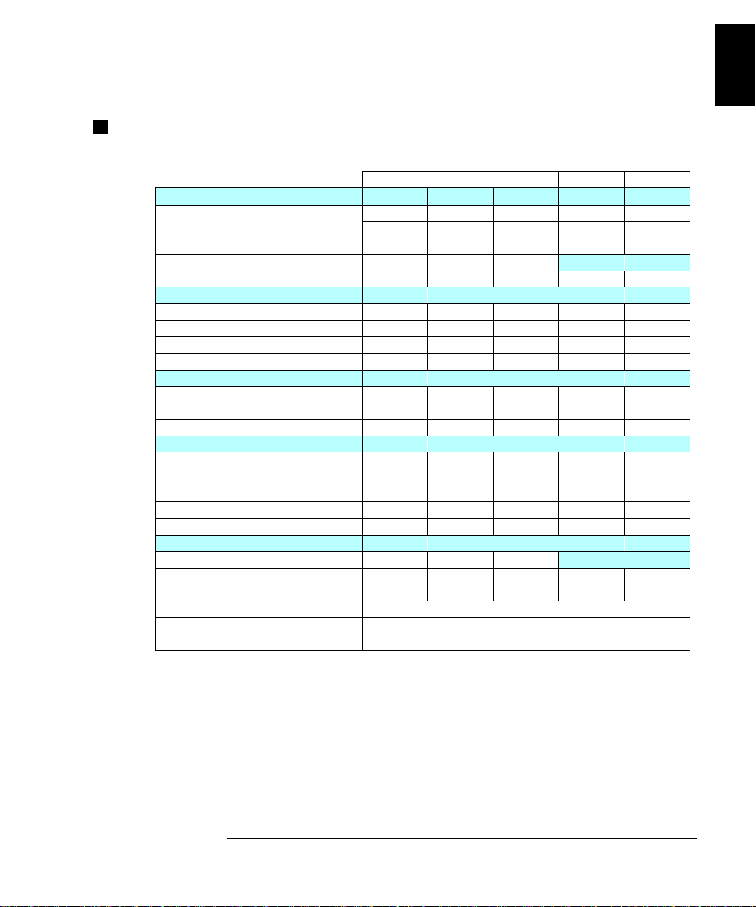
Module Specifications
34901A, 34902A, 34908A, 34903A, 34904A
General 34901A
Number of Channels 20+2 16 40 20 4x8
2/4 wire 2/4 wire 1 wire SPDT 2 wire
Connects to Internal DMM Yes Yes Yes No No
Scanning Speed
Open/Close Speed 120/s 120/s 70/s 120/s 120/s
Maximum Input
Voltage (dc, ac rms) 300 V 300 V 300 V 300 V 300 V
Current (dc, ac rms ) 1 A 50 mA 1 A 1 A 1 A
Power (W, VA) 50 W 2 W 50 W 50 W 50 W
Isolation (ch-ch, ch-earth) dc, ac rms 300 V 300 V 300 V 300 V 300 V
DC Characteristi cs
Offset Voltage
Initial Closed Channel R
Isolation (ch-ch, ch-earth) > 10 GΩ > 10 GΩ > 10 GΩ > 10 GΩ > 10 GΩ
AC Characteristi cs
Bandwidth 10 MHz 10 MHz 10 MHz 10 MHz 10 MHz
Ch-Ch Cross Talk (dB)
Capacitance HI to LO < 50 pF < 50 pF < 50 pF < 10 pF < 50 pF
Capacitance LO to Earth < 80 pF < 80 pF < 80 pF < 80 pF < 80 pF
Volt-Hertz Limit
Other
T/C Cold Junction Accuracy
Switch Life No Load (typical) 100M 100M 100M 100M 100M
Switch Life Rated Load (typical)
Temperature Operating All Modules – 0
Temperature Storage All Modules – -20
Humidity (non-condensing) All Modules – 40
[1]
[2]
[2]
[3]
10 MHz -45 -45 -18
60 ch/s 250 ch/s 60 ch/s
< 3 µV< 6 µV< 3 µV< 3 µV< 3 µV
< 1Ω < 1Ω < 1Ω < 0.2Ω < 1Ω
10
[2] [5]
(typical) 0.8 °C0.8 °C0.8 °C
[6]
100k 100k 100k 100k 100k
Multiplexer Actuator Matrix
34902A 34908A 34903A 34904A
[4]
8
108 108 108 108
[7]
°C to 55 °C
°C to 70 °C
°C / 80% R.H.
-45 -33
1
1
⁄
[1] Speeds are for 4
[2] Errors included in the DMM measurement accuracy specifications
[3] 50
Ω source, 50Ω load
digits, delay 0, display off, autozero off. Using 115 kbaud RS-232 setting.
2
[4] Isolation within channel 1 to 20 or 21 to 40 banks is -40 dB
[5] Thermocouple specifications not guaranteed when 34907A module is present
[6] Applies to resistive loads only
[7] Thermocouple measurements not recommended with 34908A module due to common LO configuration.
21
Page 24
Chapter 1 Specifications
Module Specifications
Module Specifications
34905A, 34906A
RF Multiplexer
General 34905A 34906A
Number of Channels Dual 1x4
Open/Close Speed 60/s
Maximum Input
Voltage (dc, ac rms) 42 V
Current (dc, ac rms) 0.7 A
Power (W, VA) 20 W
DC Characteristi cs
Offset Voltage
Initial Closed Channel R
Isolation (ch-ch, ch-earth) > 1 GΩ
Other
Switch Life No Load (typical) 5M
Switch Life Rated Load (ty pical)
Temperature Operating 0
Temperature Storage -20
Humidity (non-condensing) 40
[1]
[1]
50
[2]
Dual 1x4
Ω
< 6 µV
< 0.5Ω
100k
°C to 55 °C
°C to 70 °C
°C / 80% R.H.
75
Ω
The ac performance graphs are shown on the following page.
AC Characteristics 34905A 34906A
Bandwidth
Insertion Loss (dB) 10 MHz -0.1 -0.1
100 MHz -0.4 -0.4
500 MHz -0.6 -0.5
1 GHz -1.0 -1.0
1.5 GHz -1.2 -1.5
2 GHz -3.0 -2.0
SWR 10 MHz 1.02 1.02
100 MHz 1.05 1.05
500 MHz 1.20 1.25
1 GHz 1.20 1.40
1.5 GHz 1.30 1.40
2 GHz 1.40 2.00
Ch-Ch Cross T a lk (dB)
100 MHz -85 -75
500 MHz -65 -65
1 GHz -55 -50
1.5 GHz -45 -40
2 GHz -35 -35
Risetime < 300 ps
Signal Delay < 3 ns
Capacitance HI to LO < 20 pF
Volt-Hertz Limit 10
[3]
2 GHz 2 GHz
[4]
10 MHz -100 -85
10
[1] Errors included in DMM meas ur ement a ccur acy sp eci f ica tio ns
[2] Applies to resistive loads only
[3] Bandwidth direct to module SMB connectors
[4] 50
Ω source, 50Ω load
22
Page 25
Chapter 1 Specifications
Typical AC Performance Graphs
Typical AC Performanc e Gr aphs
34905A, 34906A
1
Insertion Loss (50Ω)
VSWR (50Ω)
Direct to Module
Using provided adapter cables
Insertion Loss (75Ω)
VSWR (75Ω)
Crosstalk (50Ω)
Crosstalk (75Ω)
23
Page 26

Chapter 1 Specifications
Module Specifications
Module Specifications
34907A
Digital Input / Output
Port 1, 2:
in(L):
V
V
in(H):
V
out(L):
out(H):
V
in(H) Max:
V
Alarming:
Speed
Latency
Read/Write Speed:
Totalize Input
Maximum Count:
Totalize Input:
Signal Level:
Threshold:
Gate Input:
Count Reset:
Read Speed:
8 Bit, input or output, non-isolated
< 0.8V (TTL)
> 2.0V (TTL)
< 0.8V @ Iout = - 400 mA
> 2.4V @ Iout = 1 mA
< 42V with extern al open dr ai n p ul l- up
Maskable pat ter n ma tc h or st at e ch an ge
4 ms (max) alarm sampling
5 ms (typical) to 34970A alarm output
95/s
26
2
- 1 (67,108,863)
100 kHz (max), rising or falling edge,
programmable
1 Vp-p (min)
42 Vpk (max)
0V or TTL, jumper selectable
TTL-Hi, TTL-Lo, or none
Manual or Read+Reset
85/s
Software Specifications
BenchLink Data Logge r
System Requirements
PC Hardware:
Operating System:
Computer Interfaces
GPIB:
LAN-to-GPIB:
RS-232 (Serial Port):
Performance
Scan and Save to Disk:
[1] Software provided on CD-ROM; includes utility to create
floppy disks for installation
[2] Interface and dr ive rs mus t be pu rch ase d a nd in st al le d se pa rat el y
[3] 90 MHz Pentium
[3]
®
, 20 MB RAM
(not included with Option 001)
[1]
486, 66 MHz, 16 MB RAM,
12 MB disk space
Windows
Windows NT
[2]
Agilent 82335B, 82340A/B/C,
82341A/B/C/D
National Inst r ument s A T-G PIB / TNT,
PCI-GPIB
Agilent E581 0A (Windows 98/Me/
NT/2000/XP Professional)
PC COM 1 to 4
100 ch/s, 2 strip charts displayed
®
3.1, Windows 95,
®
4.0
Analog Voltage (DAC) Output
DAC 1, 2:
Resolution:
I
out:
Settling Time:
Accuracy:
1 year
Temp Coefficient:
[1] Limited to 40 mA total for all three slots (six DAC channels)
±5 °C
±12V, non-isolated (earth referenced)
1 mV
10 mA max
1 ms to 0.01% of output
±(% of output + mV)
0.25% + 20 mV
±(0.015% + 1 mV) / °C
[1]
24
Page 27
Chapter 1 Specifications
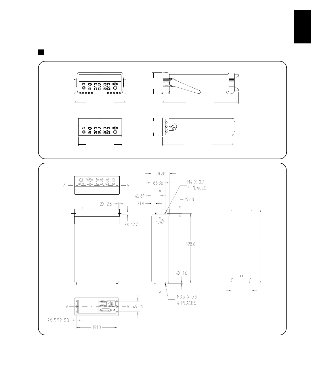
Product and Module Dimensions
Product and Module Dimensions
103.6 mm
1
254.4 mm
TOP
374.0 mm
88.5 mm
348.3 mm212.6 mm
Module
315.6
91.9
All dimensio ns are shown
in millimeters .
25
Page 28

Chapter 1 Specifications
To Calculate Total Measurement Error
To Calculate Total Measurement Error
Each specification includes correction factors which account for errors
present due to operational limitations of the internal
explains these errors and shows how to apply them t o your measurements.
Refer to “Interpreting Internal DMM Specifications,” starting on page
28, to get a better understanding of the terminology used and to help
you interpret the internal
DMM’s specifications.
DMM. This section
The internal
DMM’s accuracy specifications are expressed in the form:
(% of reading + % of range). In addition to the reading error and range
error, you may need to add additional errors for certain operating
conditions. Check the li st below to mak e sure you inc lude all mea surement
errors for a given function. Also, make sure you apply the conditions as
described in the footnotes on the specification pages.
• If you are operating the internal DMM outside the 23 °C ± 5 °C
temperature range specified, apply an additional temperature
coefficient error.
• For dc voltage, dc current, and resistance measurements, you may
need to apply an additional reading speed error.
• For ac voltage and ac current measurements, you may need to apply
an additional low frequency error or crest factor error.
Understanding the “ % of reading ” Error The reading error
compensates for inaccur acies that result from the function and range
you select, as well as the input signal level. The reading error varies
according to the input level on the selected range. This error is
expressed in percent of reading. The following table shows the reading
error applied to the internal
Range Input Level
DMM’s 24-hour dc voltage specification.
Reading Error
(% of reading)
Reading
Error Voltage
26
10 Vdc
10 Vdc
10 Vdc
10 Vdc
1 Vdc
0.1 Vdc
0.0015
0.0015
0.0015
≤ 150 µV
≤ 15 µV
≤ 1.5 µV
Page 29

Chapter 1 Specifications
To Calculate Total Measurement Error
Understanding the “ % of range ” Error The range error compensates
for inaccuracies that result from the function and range you select.
The range error contributes a constant error, expressed as a percent of
range, independent of the input signal level. The following table shows
the range error applied to the
DMM’s 24-hour dc voltage specification.
1
Range Input Level
10 Vdc
10 Vdc
10 Vdc
10 Vdc
1 Vdc
0.1 Vdc
Range Error
(% of range)
0.0004
0.0004
0.0004
Range
Error Voltage
≤ 40 µV
≤ 40 µV
≤ 40 µV
Total Measurement Error To compute the total measurement error,
add the reading error and range error. You can then convert the total
measurement error to a “percent of input” error or a “ppm (part-permillion) of input” error as shown below.
% of input error =
ppm of input error =
Example: Computing Total Measurement Error
Total Measurement Error
Input Signal Level
Total Measurement Error
Input Signal Level
× 100
× 1,000,000
Assume that a 5 Vdc signal is input to the DMM on the 10 Vdc range.
Compute the total measurement error using the 90-day accuracy
specification of
±(0.0020% of reading + 0.0005% of range).
Reading Error = 0.0020% x 5 Vdc = 100
Range Error = 0.0005% x 10 Vdc = 50
Total Error = 100
µV + 50 µV= ± 150 µV
=
± 0.0030% of 5 Vdc
=
± 30 ppm of 5 Vdc
µV
µV
27
Page 30

Chapter 1 Specifications
Interpreting Internal DMM Specifications
Interpreting Internal DMM Specifications
This section is provided to give you a better understanding of the
terminology used and will help you interpret the internal
specifications.
Number of Digits and Overrange
The “number of digits” specification is the most fundamental, and
sometimes, the most confusing characteristic of a multimeter.
The number of digits is equal to the maximum number of “9’s” the
multimeter can measure or display. This indicates the number of
full digits. Most multimeters have the ability to overrange and add
a partial or “
1
⁄
” digit.
2
DMM’s
For example, the internal
range. This represents six full digits of resolution. The internal
DMM can measure 9.99999 Vdc on the 10 V
DMM
can also overrange on the 10 V range and measure up to a maximum of
12.00000 Vdc. This corresponds to a 6
1
⁄
-digit measurement with 20%
2
overrange capability.
Sensitivity
Sensitivity is the minimum level that the multimeter can detect for a
given measurement. Sensitivity defines the ability of the multimeter to
respond to small changes in the input level. For example, suppose you
are monitoring a 1 mVdc signal and you want to adjust the level to
within
measurement would require a multimeter with a sensitivity of at least
1
range. You could also use a 4
For ac voltage and ac current measurements, note that the smallest
value that can be measured is different from the sensitivity. For the
internal
the selected range. For example, the internal
to 1 mV on the 100 mV range.
±1 µV. To be able to respond to an adjustment this small, this
µV. You could use a 6
DMM, these functions are specified to measure down to 1% of
1
⁄
-digit multimeter if it has a 1 Vdc or smaller
2
1
⁄
-digit multimeter with a 10 mVdc range.
2
DMM can measure down
28
Page 31

Chapter 1 Specifications
Interpreting Internal DMM Specifications
Resolution
Resolution is the numeric ratio of the maximum displayed value divided
by the minimum displayed value on a selected range. Resolution is
often expressed in percent, parts-per-million (ppm), counts, or bits.
For example, a 6
1
⁄
-digit multimeter with 20% overrange capability can
2
display a measurement with up to 1,200,000 counts of resolution.
This corresponds to about 0.0001% (1 ppm) of full scale, or 21 bits
including the sign bit. All four specifications are equivalent.
Accuracy
Accuracy is a measure of the “exactness” to which the internal DMM’s
measurement uncertainty can be determined relative to the calibration
reference used. Absolute accuracy includes the Internal DMM’s relative
accuracy specification plus the known error of the calibration reference
relative to national standards (such as the U.S. National Institute of
Standards and Technology ). To be meanin gful, th e accur acy specifica tion s
must be accompanied with the conditions under which they are valid.
These conditions should include temperature, humidity, and time.
1
There is no standard convention among multimeter manufacturers for
the confidence limits at which specifications are set. The table below
shows the probability of non-conformance for each specification with the
given assumptions.
Specification
Criteria
Mean ± 2 sigma
Mean ± 3 sigma
Probability
of Failure
4.5%
0.3%
Variations in performance from reading to reading, and instrument
to instrument, decrease for increasing number of sigma for a given
specification. This means that you can achieve greater actual
measurement precision for a specific accuracy specification number.
The 34970A is designed and tested to meet performance better than
mean
±3 sigma of the published accuracy specifications.
29
Page 32

Chapter 1 Specifications
Interpreting Internal DMM Specifications
24-Hour Accuracy
The 24-hour accuracy specification indicates the internal DMM’s
relative accuracy over its full measurement range for s hort time
intervals and within a stable environment. Short-term accuracy is
usually specified for a 24-hour period and for a
range.
±1 °C temperature
90-Day and 1-Year Accuracy
These long-term accuracy specifications are valid for a 23 °C ± 5 °C
temperature range. These specifications include the initial calibration
errors plus the internal DMM’s long-term drift errors.
Temperature Coefficients
Accuracy is usually specified for a 23 °C ± 5 °C temperature range.
This is a common temperature range for many operating environments.
You must add additional temperature coefficient errors to the accuracy
specification if you are operating the multimeter outside a 23 °C
temperature range (the specification is per °C).
± 5 °C
30
Page 33

Chapter 1 Specifications
Configuring for Highest Accuracy Measurements
Configuring for Highest Accuracy Measurements
The measurement configurations shown below assume that the internal
DMM is in its Factory Reset state. It is also assumed that manual
ranging is enabled to ensure proper full scale range selection.
DC Voltage, DC Current, and Resistance Measurements:
• Set the resolution to 6 digits (you can use the 6 digits slow mode for
further noise reduction).
• Set the input resistance to greater than 10 GΩ (for the 100 mV, 1 V,
and 10 V ranges) for the best dc voltage accuracy.
• Use 4-wire ohms and enable offset compensation for the best
resistance accuracy.
AC Voltage and AC Current Measurements:
• Set the resolution to 6 digits.
1
• Select the slow ac filter (3 Hz to 300 kHz).
Frequency and Period Measurements:
• Set the resolution to 6 digits.
31
Page 34

32
Page 35

2
2
Quick Start
Page 36

Quick Start
One of the first things you will want to do with your instrument is to
become acquainted with the front panel. We have written the exercises
in this chapter to prepare the instrument for use and help you get
familiar with some of its front-panel operations.
The front panel has several groups of keys to select various functions
and operations. A few keys have a shifted function printed in blue below
the key. To perform a shifted function, press (the
will turn on). Then, press the key that has the desired label below it.
For example, to select the Utility Menu, press .
SHIFT annunciator
If you accidentally press , just press it again to turn off the
annunciator.
This chapter is divided into the following sections:
• To Prepare the Instrument for Use, on page 35
• To Connect Wiring to a Module, on page 36
• To Set the Time and Date, on page 38
• To Configure a Measurement Channel, on page 39
• To Monitor a Single Channel, on page 40
• To Close a Channel, on page 41
• If the Instrument Does Not Turn On, on page 42
• To Adjust the Carrying Handle, on page 44
• To Rack Mount the Instrument, on page 45
SHIFT
34
Page 37

Chapter 2 Quick Start
To Prepare the Instrument for Use
To Prepare the Instrument for Use
1 Check the list of supplied items.
Verify that you have received the following items with your instrument.
If anything is missing, contact your nearest Agilent Technologies Sales Office.
One power cord.
One User’s Guide.
This Service Guide.
One Quick Reference Guide.
Certificate of Calibration (if you ordered the internal DMM ).
Quick Start Kit (if you ordered the internal DMM):
• One RS-232 cable.
• BenchLink Data Logger Software CD-ROM.
• One J-type thermocouple and a flatblade screwdriver.
Any plug-in modules that you ordered are delivered in a separate
shipping container.
2
On/Standby
Switch
WARNING
Note that this switch
Standby only.
is
To disconnect the
mains from the
instrumen t , remove
the power cord.
2 Connect the power cord and turn on the instrument.
The front-panel display will light up briefly while the instrument
performs its power-on self-test. The
GPIB address is displayed.
The instrument initially powers up with all measurement channels
turned off. To review the power-on display with all annunciators
turned on, hold down as you turn on the instrument. If the
instrument does not turn on properly, see page 42.
3Perform a complete self-test.
The complete self-test performs a more extensive set of tests than those
performed at power-on. Hold down as you turn on the instrument
and hold down the ke y until you hear a long beep. The self-test will begin
when you release the key f ollowing the beep.
35
Page 38

Chapter 2 Quick Start
To Connect Wiring to a Module
To Connect Wiring to a Module
1 Remove the module cov er.
3 Route wiring through strain relief.
Cable Tie Wrap
(optional)
2 Connect wiring to the screw terminals.
20 AWG
Typical
6 mm
4 Replace the module cover.
5 Install the module into mainframe.
Channel Number:
Slot Channel
36
Wiring Hints...
• For detailed information on each module,
refer to the 34970A User’ s Guide.
• To reduce wear on the internal DMM relays,
wire like functions on adjacent channels.
• Use shielded twisted pair Teflon insulated
cables to reduce settling and noise errors.
• The diagrams on the next page show how to
connect wiring to a multiplexer module for
each measurement function.
Page 39

Chapter 2 Quick Start
To Connect Wiring to a Module
Thermocouple
Thermocouple Types: B, E, J, K, N, R, S, T
2-Wire Ohms / RTD / Thermistor
Ranges: 100, 1 k, 10 k, 100 k, 1 M, 10 M, 100 MΩ
RTD Types: 0.00385, 0.00391
Thermistor Types: 2.2 k, 5 k, 10 k
DC Voltage / AC Voltage / Frequency
Ranges: 100 mV, 1 V, 10 V, 100 V, 300 V
4-Wire Ohms / RTD
2
DC Current / AC Current
Valid only on channels 21 and 22 on the 34 9 0 1 A .
Ranges: 10 mA, 100 mA, 1A
Channel n (source) is automatically paired with
Channel n+10 (sense) on the 34901A or
Channel n+8 (sense) on the 34902A.
Ranges: 100, 1 k, 10 k, 100 k, 1 M, 10 M, 100 MΩ
RTD Types: 0.00385, 0.00391
37
Page 40

Chapter 2 Quick Start
To Set the Time and Date
To Set the Time and Date
All readings during a scan are automatically time stamped and stored in
non-volatile memory. In addition, alarm data is time stamped and
stored in a separate non-volatile memory queue.
Utility
Utility
1 Set the time of day.
Use and to select the field to modify and turn the knob to change
the value. You can also edit the
AM/PM field.
TIME 03:45 PM
2 Set the date.
Use and to select the field to modify and turn the knob to change
the value.
JUNE 01 2002
38
Page 41

Chapter 2 Quick Start
To Configure a Measurement Channel
To Configure a Measurement Channel
Use this general procedure to configure a measurement channel.
1 Select the channel.
Turn the knob until the desired channel is shown on the right side of
front-panel display. The channel number is a three-digit number;
the left-most digit represents the slot number (100, 200, or 300) and the
two digits on the right indicate the channel number (102, 110, etc.).
Note: You can use and to skip to the beginning of the previous
or next slot.
2 Select the measurement parameters for the selected channel.
Use the knob to scroll through the measurement choices on each level
of the menu. When you press to make your selection, the menu
automatically guides you through all relevant choices to configure a
measurement on the selected function. When you have finished
configuring the parameters, you are automatically exited from the menu.
The present selection (or default) is displayed in full bright for easy
identification. When you make a different selection, the new choice is
shown in full bright and it becomes the default selection. The order of
the choices always remains the same; however, you always enter the
menu at the present (full-bright) setting for each parameter.
2
Note: The menu will timeout after about 20 seconds of inactivity and
any changes made previously will take effect.
39
Page 42

Chapter 2 Quick Start
To Monitor a Single Channel
To Monitor a Single Channel
You can use the Monitor function to continuously take readings on a single
channel, even during a scan. This feature is used during front pa nel
calibration procedures.
1 Select the channel to be monitored.
Only one channel can be monitored at a time but you can change the
channel being monitored at any time by turning the knob.
2 Enable monitoring on the selected channel.
Any channel that can be “read” by the instrument can be monitored
(the
MON annunciator turns on). This includes any combination of
temperature, voltage, resistance, current, frequency, or period
measurements on multiplexer channels. You can also monitor a digital
input port or the totalizer count on the multifunction module.
To disable monitoring, press again.
40
Page 43

Chapter 2 Quick Start
To Close a Channel
To Close a Channel
On the multiplexer and switch modules, you can close and open individual
relays on the module. However, note that if you have already configured
2
any multiplexer channels for scanning, you cannot independently close
and open individual relays on that module.
1 Select the channel.
Turn the knob until the desired channel is shown on the right side of
front-panel display. For this example, select channel 213.
2 Close the selected channel.
3 Open the selected channel.
Note: will sequentially open all channels on the module in the
selected slot.
The table below shows the low-level control operations available for each
of the plug-in modules.
Plug-In Module
34901A 20-Channel Mux ••• •
34902A 16-Channel Mux ••• •
34908A 40-Channel Single-Ended Mux
34903A 20-Channel Actuator ••
34904A 4x8 Matrix ••
34905A Dual 4-Channel RF Mux (50
34906A Dual 4-Channel RF Mux (75
34907A Multifunction Module (DIO) •• •
34907A Multifunction Module (Totalizer) ••
34907A Multifunction Module (DAC) •
[1]
••• •
[2]
Ω )
Ω )
[2]
•
•
,
[1] Only one channel can be closed at a time on this module.
[2] Only one channel in each bank can be closed at a time on this module.
41
Page 44

Chapter 2 Quick Start
If the Instrument Does Not Turn On
If the Instrument Does Not Turn On
Use the following steps to help solve problems you might encounter
when turning on the instrument.
1 Verify that there is ac power to the instrument.
First, verify that the power cord is firmly plugged into the power
receptacle on the rear panel of the instrument. You should also make
sure that the power source you plugged the instrument into is
energized. Then, verify that the instrument is turned on.
The On/Standby switch is located on the lower left side of the front panel.
2 Verify the power-line voltage setting.
The line voltage is set to the proper value for your country when the
instrument is shipped from the factory. Change the voltage setting if
it is not correct. The settings are: 100, 120, 220, or 240 Vac.
Note: For 127 Vac operation, use the 120 Vac setting.
For 230 Vac operation, use the 220 Vac setting.
See the next page if you need to change the line-voltage setting.
3 Verify that the power-line fuse is good.
The instrument is shi pped from th e factor y with a 500 m A fuse ins talled .
This is the correct fuse for all line voltages.
See the next page if you need to replace the power-line fuse.
To replace the 500 mAT, 250 V fuse, order Agilent part number 2110-0458.
42
Page 45

Chapter 2 Quick Start
If the Instrument Does Not Turn On
1 Remove the power cord. Remove the
fuse-holder assembly from the rear panel.
3 Rotate the line-voltage selector until the
corr ect voltage appears in the window.
2 Remove the line-voltage selector from
the assembly.
Fuse: 500 mAT (for all line voltages)
Agilent Part Number: 2110-0458
4 Replace the fuse-holder assembly in
the rear panel.
2
100, 120 (127), 220 (230) or 240 Vac
Verify that the correct line voltage is selected and the power-line fuse is good.
43
Page 46

Chapter 2 Quick Start
To Adjust the Carrying Handle
To Adjust the Carrying Handle
To adjust the position, grasp the handle by the sides and pull outward.
Then, rotate the handle to the desired position.
44
Carrying PositionBenchtop Viewing Positions
Page 47

Chapter 2 Quick Start
To Rack Mount the Instrument
To Rack Mount the Instrument
You can mount the instrument in a standard 19-inch rack cabinet using
one of three optional kits available. Instructions and mounting
hardware are included with each rack-mounting kit. Any System II
instrument of the same size can be rack-mounted beside the 34970A.
Remove the carrying handle, and the front and rear rubber bumpers,
before rack-mounting the instrument.
To remove the handle, rotate it to the vertical p osition an d pull t he ends outward.
2
Front Rear (bottom view)
To remove the rubber bumper, stretch a corner and then slide it off.
45
Page 48

Chapter 2 Quick Start
To Rack Mount the Instrument
To rack mount a single instrument, order adapter kit 5063-9240.
To rack mount two instruments side-by-side, order lock-link kit 5061-9694 and
flange kit 5063-9212. Be sure to use the support rails inside the rack cabinet.
To install one or two instruments in a sliding support shelf, order shelf 5063-9255,
and slide kit 1494-0015 (for a single instrument, also order filler panel 5002-3999).
46
Page 49

3
3
Front-Panel
Overview
Page 50

Front-Panel Overview
This chapter introduces you to the front-panel keys and menu operation.
This chapter does not give a detailed description of every front-panel
key or menu operation. It does, however, give you a good overview of
the front-panel menu and many front-panel operations. See the Agilent
34970A User’s Guide for a complete discussion of the instrument’s
capabilities and operation.
This chapter is divided into the following sections:
• Front-Panel Menu Reference, on page 49
• To Unsecure for Calibration, on page 51
• To Secure Against Calibration, on page 51
• To Change the Security Code, on page 52
• Error Messages, on page 52
• To Perform a Zero Adjustment, on page 53
• To Apply Mx+B Scaling to Measurements, on page 54
• To Read the Relay Cycle Count, on page 55
• To Read a Digital Input Port, on page 56
• To Write to a Digital Output Port, on page 57
• To Read the Totalizer Count, on page 58
• To Output a DC Vo ltage, on page 59
48
Page 51

Chapter 3 Front-Panel Overview
Front-Panel Menu Reference
Front-Panel Menu Reference
This section gives an overview of the front-panel menus. The menus are
designed to automatically guide you through all parameters required to
configure a particular function or operation. The remainder of this
chapter shows examples of using the front-panel menus.
Configure th e measurement parameters on the displayed ch annel.
• Select measure me nt function (dc volts, oh ms, etc.) on the displaye d channel.
• Select transducer type for temperature measurements.
• Select units (°C, °F, or K) for temperature measurements.
• Select measureme nt rang e or au to ran ge .
• Select measureme nt resolution.
• Copy and paste measurement configuration to other ch an ne ls .
Configure the scaling parameters for the displayed channel.
• Set the gain (“M”) and offset (“B”) value for the displayed channel.
• Make a null measurement and store it as the offset value.
• Specify a custom la be l (RPM, PSI, etc.) for the displa ye d ch annel.
3
Configure al arms on the displayed channel.
• Select one of fou r ala rms to report alarm condit io ns on th e di sp la yed channel.
• Configure a hi gh lim it , lo w lim it , or bo th for the displayed chan ne l.
• Configure a bit pattern which will generate an alarm (for digital input channels).
Configure the four Alarm Outp ut ha rdw a re li ne s.
• Clear the state of the four alarm output lines.
• Select the “Latch” or “Track” mode for the four alarm output lines.
• Select the slope (ris in g or fa ll ing edge) for the four alarm out pu t lines.
Configure the event or action that controls the scan interval.
• Select the scan int erv al mod e (in te rva l, manual, external, or al arm) .
• Select the scan cou nt.
49
Page 52

Chapter 3 Front-Panel Overview
Front-Panel Menu Reference
Configure the advanced measurement features on displayed channel.
• Set the integration time for measurements on the displayed channel.
• Set the channel-to-channel delay for scanning.
• Enable/disabl e th e th erm oc ou pl e ch ec k fe ature (T/C measurement s only ).
• Select the refere nce ju nc ti on source (T/C measurement s on ly ).
• Set the low frequency limit (ac m easurements only).
• Enable/disable offset compensation (resistance measurements only).
• Select the binary or decimal mode for digital operations (34907A on ly ).
• Configure the to ta lizer reset mode (total iz er on ly ).
• Select which edge is detected (rising or falling) for totalizer operations.
Configure system-related instrument parameters.
• Set the real-time system clock and calendar.
• Query the firmware revisions for the mainframe and installed modules.
• Select the inst rumen t ’ s pow er-o n co nf ig uration (last or factory rese t).
• Enable/disable the internal DMM.
• Secure/unsecure the instrument for calibration.
View readings, alarms, and errors.
• View the last 100 sc anned readings from memo ry (last, min, max, and av era ge ).
• View the first 20 alarms in the alarm queue (reading and time alarm occurred).
• View up to 10 errors in the error queue.
• Read the number of cycles for the disp layed relay (relay maintenance feature).
Store and recall in stru me nt sta tes.
• Store up to five inst rument states in non-volatile memory.
• Assign a name to ea ch storage location.
• Recall stored st ates, power-down state , factory reset state, or pr es et sta te .
Configure the remote interfa ce .
• Select the GPIB addre ss.
• Configure the RS -23 2 in te rfa ce (bau d rat e, pari ty , an d fl ow co ntrol).
50
Page 53

Chapter 3 Front-Panel Overview
To Unsecure for Calibration
To Unsecure for Calibration
You can unsecure the instrument either from the front panel or over the
remote interface. The instrument is secured when shipped from the
factory and the security code is set to “
HP034970”.
• Once you enter a security code, that code must be used for both
front-panel and remote operation. For example if you secure the
instrument from the front panel, you must use that same code to
unsecure it from the remote interface.
• Press to enter the Utility menu.
When you first enter the Utility menu, the calibration entries toggle
between
instrument, select
correct security code, press again. When you return to the menu,
you will see new choices
Note: If you enter the wrong secure code,
and a new choice,
CAL SECURED and UNSECURE CAL. To unsecure the
UNSECURE CAL and press . After entering the
CAL UNSECURED and SECURE CAL.
NO MATCH is displayed
EXIT, is shown.
To Secure Against Calibration
You can secure the instrument either from the front panel or over the
remote interface. The instrument is secured when shipped from the
factory and the security code is set to “
• Once you enter a security code, that code must be used for both
front-panel and remote operation. For example if you secure the
instrument from the front panel, you must use that same code to
unsecure it from the remote interface.
HP034970”.
3
• Press to enter the Utility menu.
When you enter the Utility menu, the calibration entries toggle
between
instrument, select
desired security code, press again. When you return to the
menu, you will see new choices
CAL UNSECURED and SECURE CAL. To secure the
SECURE CAL and press . After entering the
CAL SECURED and UNSECURE CAL.
51
Page 54

Chapter 3 Front-Panel Overview
To Change the Security Code
To Change the Security Code
• To change the security code, you must first unsecure the instrument,
and then enter a new code. Make sure you have read the security
code rules described on page 67 before attempting to change the
security code.
• To change the security code, first make sure that the instrument is
unsecured. Go to the
and press (the instrument is now secured with the new code).
Changing the code from the front panel also changes the code as seen
from the remote interface.
SECURE CAL entry, enter the new security code,
Error Messages
Error messages are retrieved in a first-in first-out (FIFO) order.
When the ERROR annunciator is on, press to view error
messages. Use the arrow keys to scroll the message in the display.
A list of the self-test errors messages and their meanings begin on
page 168.
For a complete list of error messages and descriptions, see chapter 6 in
the 34970A User’s Guide.
52
Page 55

Chapter 3 Front-Panel Overview
To Perform a Zero Adjustment
To Perform a Zero Adjustment
The instrument features closed case electronic calibration. No internal
mechanical adjustments are required. The instrument calculates
correction factors based upon an input reference value an d stores the
correction factors in non-volatile memory. This procedure demonstrates
making the zero adjustment from the front panel. The gain adjustments
are similar.
DO NOT perform this procedure before reading Chapter 4. Chapter 4
describes this procedure, the required input connections, input signals,
and test considerations required for a valid adjustment.
1 Configure the channel.
You must configure a channel before applying performing the
adjustment procedure. Configure the ch annel to DC VOLTS
1
and 6
⁄
digits.
2
2 Apply the input signal
In this example, the input signal is a copper short (see page 66).
3 Setup the calibration.
The display will show PERFORM CAL..
4 Set the adjustment value.
The display will show the a number. Edit the number to the actual
input value. For the Zero Adjustment, the input value is 0.000000.
+000.000,000 mVDC
5 Begin the adjustment.
The display will show the progress of the adjustment. When all the
adjustments are completed, the display will show done.
3
DONE
53
Page 56

Chapter 3 Front-Panel Overview
To Apply Mx+B Scaling to Measurements
To Apply Mx+B S caling to Measure ments
The scaling function all ows you to apply a gain and offset to all readings
on a specified multiplexer channel during a scan. In addition to setting
the gain (“M”) and offset (“B”) values, you can also specify a custom
measurement label for your scaled readings (
1 Configure the channel.
You must configure the channel (function, transducer type, etc.) before
applying any scaling values. If you change the measurement
configuration, scaling is turned off on that channel and the gain and
offset values are reset (M=1 and B=0).
2 Set the gain and offset values.
The scaling values are stored in non-volatile memory for the specified
channels. A Factory Reset turns off scaling and clears the scaling values
on all channels. An Instrument Preset or Card Reset does not clear the
scaling values and does not turn off scaling.
RPM, PSI, etc.).
+1.000,000
-0.700,000 OHM
3 Select the custom label.
You can specify an optional three-character label for your scaled
readings (
unit for the selected function (
LABEL AS OHM
4 Scaling is now applied to the measurements.
54
RPM, PSI, etc.). The default label is the standard engineering
Set Gain
Set Offset
VDC, OHM, etc.).
Page 57

Chapter 3 Front-Panel Overview
To Read the Relay Cycle Count
To Read the Relay Cycle Count
The instrument has a Relay Maintenance System to help you predict
relay end-of-life. The instrument counts the cycles on each relay in the
instrument and stores the total count in non-volatile memory on each
switch module. You can use this feature on any of the relay modules and
the internal
• In addition to the channel relays, you can also query the count on
backplane relays and bank relays. Note that you cannot control the
state of these relays from the front panel but you can query the count.
• You can also query the state of the three relays on the internal DMM.
These relays are numbered “1”, “2”, and “3” (which correspond to
relays K102, K103, and K104 respectively). These relays open or close
when a function or range is changed on a module.
• The 34908A multiplexer c ontain s 40 cha nnels whic h are swit ched
(
HI only) using only 20 relays. Each relay is used to switch HI on two
different channels (and only one channel can be closed at a time).
The channels are arranged such that channels 01 and 21 use di fferent
contacts on the same relay . The remain ing cha nnels ar e also pair ed in
the same manner (channels 02 and 22, channels 03 and 23, etc.).
Therefore, when you query the relay count on a cha nnel, the number
reflects the number of times that the relay was closed. For example,
the relay count will al ways be the same on channel s 01 and 21 .
DMM.
3
• For more information on relay life and load considerations, refer to
“Relay Life and Preventative Maintenance” in the 34970A User’s Guide.
• To read the count on the active channel, choose the following item
and then turn the knob. To read the count on the internal
relays, turn the knob counterclockwise beyond the lowest numbered
channel in the instrument. To read the “hidden” relays, turn the knob
clockwise beyond the highest numbered channel in the current slot.
RELAY CYCLES
DMM
55
Page 58

Chapter 3 Front-Panel Overview
To Read a Digital Input Port
To Read a Digital Input Port
The multifunction module (34907A) has two non-isolated 8-bit
input/output ports which you can use for reading digital patterns.
You can read the live status of the bits on the port or you can configure
a scan to include a digital read.
1 Select the Digital Input port.
Select the slot containing the multifunction module and continue
turning the knob until
2 Read the specified port.
You can specify whether you want to use binary or decimal format.
Once you have selected the number base, it is used for all input or
output operations on the same port. To change the number base,
press the key and select
DIN is displayed (channel 01 or 02).
USE BINARY or USE DECIMAL.
01010101 DIN
Bit 7 Bit 0
Binary Display Shown
The bit pattern read from the port will be displayed until you press
another key, turn the knob, or until the display times out.
Note: To add a digital input channel to a scan list, press and select
the
DIO READ choice.
56
Page 59

Chapter 3 Front-Panel Overview
To Write to a Digital Output Port
To Write to a Digital Output Port
The multifunction module (34907A) has two non-isolated 8-bit
input/output ports which you can use for outputting digital patterns.
1 Select the Digital Output port.
Select the slot containing the multifunction module and continue
turning the knob until
2 Enter the bit pattern editor.
Notice that the port is now converted to an output port (
00000000 DOUT
Bit 7 Bit 0
3 Edit the bit pattern.
Use the knob and or keys to edit the individu al bit values.
You can specify whether you want to use binary or decimal format.
Once you have selected the number base, it is used for all input or
output operations on the same port. To change the number base,
press the key and select
240 DOUT
DIN is displayed (channel 01 or 02).
DOUT).
Binary Display Shown
USE BINARY or USE DECIMAL.
Decimal Display Shown
3
4 Output the bit pattern to the specified port.
The specified bit pattern is latched on the specified port. To cancel an
output operation in progress, wait for the display to time out.
57
Page 60

Chapter 3 Front-Panel Overview
To Read the Totalizer Count
To Read the Totalizer Count
The multifunction module (34907A) has a 26-bit totalizer which can
count
TTL pulses at a 100 kHz rate. You can manually read the totalizer
count or you can configure a scan to read the count.
1 Select the totalizer c h a n nel .
Select the slot containing the multifunction module and continue
turning the knob until
2 Configure the totalize mode.
The internal count starts as soon as you turn on the instrument.
You can configure the totalizer to reset the count to “0” after being read
or it can count continuously and be manually reset.
READ + RESET
TOTALIZE (channel 03) is displayed.
3 Read the count.
The count is read once each time you press ; the count does not
update automatically on the display. As configured in this example,
the count is automatically reset to “0” each time you read it.
12345 TOT
The count will be displayed until you press another key, turn the knob,
or until the display times out. To manually reset the totalizer count,
press .
Note: To add a totalizer channel to a scan list , press and select the
TOT READ choice.
58
Page 61

Chapter 3 Front-Panel Overview
To Output a DC Volta ge
To Output a DC Voltage
The multifunction module (34907A) has two analog outputs capable of
outputting calibrated voltages between
±12 volts.
1Select a
Select the slot containing the multifunction module and continue
turning the knob until
2 Enter the output voltage editor.
+00.000 V DAC
3 Set the desired output voltage.
Use the knob a nd or keys to edit the individual digits.
+05.250 V DAC
4 Output the voltage from the se l ec t ed
The output voltage will be displayed until you press another key or turn
the knob. To manually reset the output voltage to 0 volts, press .
DAC Output channel.
DAC is displayed (channel 04 or 05).
DAC.
3
59
Page 62

60
Page 63

4
4
Calibration Procedures
Page 64

Calibration Procedures
This chapter contains procedures for verification of the instrument’s
performance and adjustment (calibration). These procedures are
required only if the internal DMM is installed. The chapter is divided
into the following sections:
• Agilent Technologies Calibration Services, on page 63
• Calibration Interval, on page 63
• Time Required for Calibration, on page 64
• Automating Calibration Procedures, on page 64
• Recommended Test Equipment, on page 65
• Input connections, on page 66
• Calibration Security, on page 67
• Calibration Message, on page 69
• Calibration Count, on page 69
• Calibration Procedures, on page 70
• Aborting a Calibration in Progress, on page 70
• Test Considerations, on page 71
• Performance Verification Tests, on page 72
• Internal DMM Verification Tests, o n page 75
• Optional AC Performance Verification Tests, on page 80
• Internal DMM Adjustments, on page 81
• –10 Vdc Adjustment Procedure (Optional), on page 85
• Plug-in Module Test Considerations, on page 87
• Relay Verification, on page 88
• Thermocouple Reference Junction (Optional), on page 112
• 34907A Analog Output, on page 114
Closed-Case Electronic Calibration The instrument feature s
closed-case electronic calibration. No internal mechanical
adjustments are required. The instrument calculates correction
factors based upon the input reference value you set. The new
correction factors are stored in non-volatile memory until the next
calibration adjustment is performed. Non-volatile EEPROM
calibration memory does not change when power has bee n off or
after a remote interface reset.
62
Page 65

Chapter 4 Calibration Procedures
Agilent Technologies Calibration Services
Agilent Technologies Calibration Services
When your instrument is due for calibration, contact your local
Agilent Service Center for a low-cost recalibration. The 34970A is
supported on automated calibration systems which allow Agilent to
provide this service at competitive prices.
Calibration Interval
The instrument should be calibrated on a regular interval determined
by the measurement accuracy requirements of your application.
A 1-year interval is adequate for most applications. Accuracy
specifications are warranted only if adjustment is made at regular
calibration intervals. Accuracy specifications are not warranted
beyond the 1-year calibration interval. Agilent does not recommend
extending calibration intervals beyond 2 years for any application.
Adjustment is Re c om m e nd e d
4
Whatever calibration int erval you select, Agilent recommends that
complete re-adjustment should always be performed at the calibration
interval. This will assure that the 34970A will remain within
specification for the next calibration interval. This criteria for
re-adjustment provides the best long-term stability. Performance
data measured using this method can be used to extend future
calibration intervals.
Use the Calibration Count feature (see page 69) to verify that all
adjustments have been performed.
63
Page 66

Chapter 4 Calibration Procedures
Time Required for Calibration
Time Required for Calibration
The 34970A can be automatically calibrated under computer control.
With computer control you can perform the comple te calibration
procedure and performance verification tests in less than 30 minutes
once the instrument is warmed-up (see “Test Considerations” on page 71).
Manual calibrations using the recommended test equipment will take
approximately 2 hours.
Automating Calibration Procedures
You can automate the complete verification and adjustment
procedures outlined in this chapter if you have access to
programmable test equipment. You can program the instrument
configurations specified for each test over the remote interface.
You can then enter readback verification data into a test program
and compare the results to the appropriate test limit values.
You can also adjust the instrument from the remote interface.
Remote adjustment is similar to the local front-panel procedure.
You can use a computer to perform the adjustment by first selecting
the required function and range. The calibration value is sent to the
instrument and then the calibration is initiated over the remote
interface. The instrument must be unsecured prior to initiating
the calibration procedure.
For further information on programming the instrument,
see chapter 5 in the 34970A User’s Guide.
64
Page 67

Chapter 4 Calibration Procedures
Recommended Test Equipment
Recommended Test Equipment
The test equipment recommended for the performance verification
and adjustment procedures is listed below. If the exact instrument is
not available, substitute calibration standards of equivalent accuracy.
A suggested alternate method would be to use the Agilent 3458A 8
digit Digital Multimeter to measure less accurate yet stable sources.
The output value measured from the source can be entered into the
instrument as the target calibration value.
Application Recommended Equipment Accuracy Requirements
Zero Calibration
DC Voltage
DC Current
Resistance
AC Voltage
AC Current
Frequency
Analog Output
34907A
Thermocouple
Reference Junction
34901A
34902A
34908A
Relay contact resistance
All switch modu le s
[1]
[1]
[1]
[1]
[1]
[1]
[1]
[1] In addition to the internal DMM, these applications require an input multiplexer module.
The 34901A is recommended.
[2] Thermistor YSI 44031 is available as Agilent part number 34308A (package of five).
None 4 -terminal all copper short
Fluke 5700A <1/5 instrument 24 hour spec
Fluke 5700A/ 57 25A <1/5 instrument 24 hour spec
Fluke 5700A <1/5 instrument 24 hour spec
Fluke 5700A/ 57 25A <1/5 instrument 24 hour spec
Fluke 5700A/ 57 25A <1/5 instrument 24 hour spec
Agilent 33220A <1/5 instrumen t 24 hou r spe c
Agilent 34401A <1/5 instrumen t 24 hou r spe c
Thermistor YSI 4403 1 (tw o )
J Type Calibrated Thermocouple
Triple Point Cell
Agilent 34401A
[2]
± 0.1 °C
± 0.001Ω resolution
1
⁄
-
2
4
65
Page 68

Chapter 4 Calibration Procedures
Input Connections
Input Connections
You will need an input multiplexer module to verify or adjust the
internal DMM. Input connections can be made using a 34901A
20-Channel Multiplexer.
To use a 34901A to completely verify and adjust the internal DMM,
make the following connections:
34901A
Connections for
DC/AC Current
Note: Use shielded twisted pair Teflon
and noise errors. Connect the shield to the source LO output.
Connections for
4-wire Ohms
Connections for DC V, AC V,
2- and 4-wire Ohms
Copper Short
insulated cables to reduce settling
To
Calibrator
You can also use a 34902A for test and adjustment of voltage,
frequency , and resistance function s. You cannot test or adjust current
inputs with a 34902A. If you use a 34902A; connect the copper shorts
to Channels 7 and 15 and make the input connections to
Channels 8 and 16.
Teflon® is a registered trademark of E.I. du Pont de Nemours and Company.
66
Page 69

Chapter 4 Calibration Procedures
Calibration Security
Calibration Security
This feature allows you to enter a security code to prevent accidental
or unauthorized adjustments of the instrument. When you first
receive your instrument, it is secured. Before you can adjust the
instrument, you must unsecure it by entering the correct security code.
See page 51 in Chapter 3 for a procedure to enter the security code.
• The security code is set to “HP034970” when the instrument is
shipped from the factory. The security code is stored in
non-volatile memory, and does not change when power has been
off, after a Factory Reset (*RST command), or after an Instrument
Preset (SYSTem:PRESet command).
• The security code may contain up to 12 alphanumeric characters.
The first character must be a letter, but the remaining characters
can be letters, numbers, or an underscore ( _ ). You do not have to use
all 12 character s but the fir st cha ract er must al ways be a letter .
Note: If you forget your security code, you can disable the security
feature by adding a jumper inside the instrument as described on the
following page.
4
67
Page 70

Chapter 4 Calibration Procedures
Calibration Security
To Unsecure the Instrum ent Without the Sec urity Code
To unsecure the instrument without the correct security code, follow
the steps below. A front panel procedure to unsecure the instrument
is given on page 51. See “Electrostatic Discharge (ESD) Precautions”
on page 162 before beginning this procedure.
Warning
Warning
• Exposed Mains
• Do Not Touch!
SHOCK HAZARD. Only service-trained personnel who are aware
of the hazards involved should remove the instrument covers.
The procedures in this section require that you connect the power
cord to the instrument with the covers removed. To avoid
electrical shock and personal injury, be careful not to touch the
power-line connections.
1 Disconnect the power cord and all input connections.
2 Remove the instrument cover (see page 174). Turn the instrument over.
3 Apply power and turn on the instrument.
Be careful not to touch the power line connectio ns.
4 Apply a short between the two exposed metal pads marked
CAL UNLOCK as shown in the figure below.
Apply Short
5 While maintaining the short, enter any unsecure code.
The instrument is now unsecured.
6 Remove the short.
7 Turn off the instrument and remove the power cord. Reassemble the
instrument.
Now you can enter a new security code. Be sure to remember the new
security code.
68
Page 71

Chapter 4 Calibration Procedures
Calibration Message
Calibration Message
The instrument allows you to store one message in calibration
memory. For example, you can store such information as the date
when the last calibration was performed, the date when the next
calibration is due, the instrument’s serial number, or even the name
and phone number of the person to contact for a new calibration.
• You can record a calibration message only from the remote
interface and only when the instrument is unsecured. You can
read the message from either the front-panel or over the remote
interface. You can read the calibration message whether the
instrument is secured or unsecured.
• The calibration message may contain up to 40 characters. From
the front panel, you can view 13 chara cters of t he message at a t ime.
Press to scroll through the text of the message. Press
again to increase the scrolling speed.
Calibration Count
You can query the instrument to determine how many calibrations
have been performed. Note that your instrument was calibrated
before it left the factory. When you receive your instrument, be sure
to read the count to determine its initial value.
• The calibration count increments up to a maximum of 65,535 after
which it rolls over to “0”. Since the value increments by one for
each calibration point, a complete calibration may increase the
value by many counts.
• The calibration count is also incremented with calibrations of the
DAC channels on the multifunction module.
• Front-Panel Operation:
CAL COUNT
• Remote Interface Operation:
4
CALibration:COUNt?
69
Page 72

Chapter 4 Calibration Procedures
Calibration Procedure
Calibration Procedure
The following procedure is the recommended method to complete an
instrument calibration.
1 Read “Test Considerations” (page 71).
2 Unsecure the instrument for calibration (page 51).
3 Perform the verification tests to characterize the instrument
(incoming data).
4 Perform the zero adjustment procedures.
5 Perform the gain adjustment procedures. Perform the verification
tests to verify the adjustments (outgoing data).
6 Secure the instrument against calibration.
7 Note the new security code and calibration count in the
instrument’s maintenance records.
CAUTION
Aborting a Calibration in Progress
Sometimes it may be necessary to abort a calibration after the
procedure has already been initiated. You can abort a calibration at
any time by turning off the power. When performing a calibration
from the remote interface, you can abort a calibration by issuing a
remote interface device clear message.
If you abort a calibration in progress when the instrument is attempting
to write new calibration constants to EEPROM, you may lose all
calibration constants for the function. Typ ic al ly , up on re-applying
power, the instrument will report error 705 Cal:Aborted. You may
also generate errors 740 through 746. If this occurs, you should not use
the instrument until a complete re-adjustment has been performed.
70
Page 73

Chapter 4 Calibration Procedures
Test Considerations
Test Considerations
To ensure proper instrument operation, verify that you have selected
the correct power line voltage prior to attempting any procedure in
this chapter. See “If the Instrument Does Not Turn On”, on page 42.
Errors may be induced by ac signals present on the input leads
during a self-test. Long test leads can also act as an antenna causing
pick-up of ac signals.
For optimum performance, all procedures should comply with the
following recommendations:
• Assure that the calibration ambient temperature is stable and
between 18
performed at 23
• Assure ambient relative humidity is less than 80%.
• Allow a 2-hour warm-up period with a copper short connected and
the multiplexer module installed before verification or adjustment.
The connections are shown in the figure on page 66.
• Use shielded twisted pair Teflon
settling and noise er ro rs. Keep the inpu t ca bl es a s shor t a s p ossi ble.
• Connect the input cable shield to the source LO output.
Except where noted in the procedures, connect the calibrator LO
source to earth ground.
Two-wire Ohms measurements are affected by the entire path length,
including the plug-in card trace length and slot trace lengths. On the
34901A, Channel 10 is recommended as the median path length
(on the 34902A, use Channel 8) for 2-wire Ohms verification and
adjustments. Install the input multipl exer in sl ot 20 0.
Because the instrument is capable of making highly accurate
measurements, you must take special care to ensure that the
calibration standards and test procedures used do not introduce
additional errors. Ideally, the standards used to verify and adjust the
instrument should be an order of magnitude more accurate than each
instrument range full scale error specification.
°C and 28 °C. Ideally the calibration should be
°C ±1 °C.
®
insulated cables to reduce
4
For the dc voltage, dc current, and resistance gain verification
measurements, you should take care to ensure the calibrator’s “0"
output is correct. If necessary, the measurements can be referenced to
the calibrator’s ”0" outpu t using Mx + B scal ing (se e page 54). You will
need to set the offset for each range of the measuring function being verified.
71
Page 74

Chapter 4 Calibration Procedures
Performance Verification Tests
Performance Verification Tests
Use the Performance verification Tests to verify the measurement
performance o f the instrument . The performance verification tests
use the instrument’s specifi cation s listed in c hapt er 1, “Speci ficati ons,”
starting on page 15.
You can perform four different levels of performance verification tests:
• Self-Test A series of internal verification tests that give a high
confidence that the instrument is operational.
• Quick Verification A combination of the internal self-tests and
selected verification tests.
• Performance Verification Tests An extensive set of tests that
are recommended as an acceptance test when you first receive the
instrument or afte r performing adjustments.
• Optional Ver i f i cation Tests Tests not perfor med with every
calibration. Perform these tests to verify additional specifications
or functions of the instrument.
72
Page 75

Chapter 4 Calibration Procedures
Performance Verification Tests
Self-Test
A brief power-on self-test occurs automatically whenever you turn on the
instrument. This limi ted test assur es that the instrum ent is capa ble of
operation and also checks the plug-in cards for basic operation.
To perform a complete self-test hold down the key as you press
the power switch to turn on the instrument; hold down the key
for more than 5 seconds until the instrument beeps (a complete
description of these tests can be found in chapter 6). The instrument
will automatically perform the complete self-test procedure when you
release the key. The self-test will complete i n approximately 20 seconds.
• If the self-test is successful, “PASS” is displayed on the front panel.
• If the self-test fails, “FAIL” is displayed and the ERROR
annunciator turns on. If repair is required, see chapter 6,
“Service,” for further details.
• If all tests pass, you have a high confidence (~90%) that the
instrument is operational.
4
73
Page 76

Chapter 4 Calibration Procedures
Performance Verification Tests
Quick Performance Check
The quick performance check is a combination of internal self-test
and an abbreviated performance test (specified by the letter Q in the
performance verification tests). This test provides a simple method to
achieve high confidence in the instrument’s ability to functionally
operate and meet specifica tions. These tests represent the absolute
minimum set of performance checks recommended following any
service activity. Auditing the instrument’s performance for the quick
check points (designated by a Q) verifies performance for “normal”
accuracy drift mechanisms. This test does not check for abnormal
component failures.
To perform the quick performance check, do the following:
• Perform a complete self-test. A procedure is given on page 73.
• Perform only the performance verification tests indicated with the
letter Q .
If the instrument fails the quick performance check, adjustment or
repair is required.
Performance Verification Tests
The performance verification tests are recommended as acceptance
tests when you first receive the instrument. The acceptance test
results should be compared against the 90 day test limits. You should
use the 24-hour test limits only for verification within 24 hours after
performing the adjustment procedure. After acceptance, you should
repeat the performance verification tests at every calibration interval.
If the instrument fails performance verification, adjustment or repair
is required.
Adjustment is recommend ed at every calib ration inte rval. I f adjustm ent
is not made, you must guar d ban d, using no more than 80 % of the
specifications listed in Chap ter 1, as the ver ifica tion lim its.
74
Page 77

Chapter 4 Calibration Procedures
Internal DMM Verification Tests
Internal DMM Verification Tests
These procedures use inputs connected to a 34901A 20-Channel
Multiplexer (see page 66) installed in slot 200.
Zero Offset Verification
This procedure is used to check the zero offset performance of the
internal DMM. Verification checks are only performed for those
functions and ranges with unique offset calibration constants.
Measurements are checked for each function and range as described
in the procedure below.
Zero Offset Veri f ication Procedure
1 Make sure you have read “Test Considerations” on page 71.
2 This procedure will measure the shorts installed on Channels 209
and 219. Leave the Am ps input c o n nections ( C hanne l 221) open .
Continued on next page...
4
75
Page 78

Chapter 4 Calibration Procedures
Internal DMM Verification Tests
Continued from previous page...
1 Select each function and range in the order shown in the table below.
Before executing each test, you must press to enable reading
monitoring on the selected channel (or use the ROUTe:MON command
from the remote interface). Compare measurement results to the
appropriate test limits shown in the table (see page 74).
Input
Open
Open
Open
Input
Short
Short
Short
Short
Short
Short
2-Wire Ohms
Short
Short
Short
Short
Short
Short
[1] Select 61⁄2 digit resolution.
[2] For 2-wire ohms, an additional 4
Q: Quick performance verification test points.
Channel 221
[1]
Function
Range
DC Current 10 mA
100 mA
1 A
Channel 209
[1]
Function
Range
DC Volts 100 mV
1 V
10 V
100 V
300 V
[2]
100
and
4-Wire Ohms
1 kΩ
10 kΩ
100 kΩ
1 MΩ
10 MΩ
100 MΩ
Ω
Ω of error must be added.
Quick
Check
Q
Quick
Check
Q
Q
Error from Nominal
24 hour 90 day 1 year
± 1 µA
± 4 µA
± 60 µA
± 2
± 5 µA
± 100 µA
µA
± 2 µA
± 5 µA
± 100 µA
Error from Nominal
24 hour 90 day 1 year
µV
± 3.5
± 6 µV
± 40 µV
± 600 µV
± 6 mV
± 3.5 mΩ
6 mΩ
±
50 mΩ
±
±
500 mΩ
10 Ω
±
±
100 Ω
10 kΩ
±
± 4 µV
± 7 µV
± 50 µV
± 600 µV
± 9 mV
±
4 mΩ
10 mΩ
±
100 mΩ
±
±
1 Ω
10 Ω
±
±
100 Ω
10 kΩ
±
± 4 µV
± 7 µV
± 50 µV
± 600 µV
± 9 mV
±
±
±
±
±
±
±
Note: Zero offset calibration using a multifunction calibrator is
NOT recommended. The c alibrator and cabling offset can be large
and unstable causing poor offset calibration of the internal DMM.
4 mΩ
10 mΩ
100 mΩ
1 Ω
10 Ω
100 Ω
10 kΩ
76
Page 79

Chapter 4 Calibration Procedures
Internal DMM Verification Tests
Gain Verification
This procedure is used to check the “full scale” reading accuracy of
the internal DMM. Verification checks are performed only for those
functions and ranges with unique gain calibra tion constants.
Begin verification by selecting a measuring function and range.
Make sure you have read “Test Considerations” on page 71.
DC VOLTS, Resistance, and DC CURRENT Gain Verification Test
1 Make sure you have read “Test Considerations” on page 71.
2 Select each function and range in the order shown below.
Before executing each test, you must press to enable reading
monitoring on the selected channel (or use the ROUTe:MON command
from the remote interface).
3 Compare measurement results to the appropriate test limits shown
in the table. (Be certain to allow for appropriate source settling.)
4
Input
100 mV
1 V
10 V
100 V
300 V
Channel 210
[1]
Function
Range
DC Volts 100 mV
1 V
10 V
100 V
300 V
Quick
Check
Q
Q
Error from Nominal
24 hour 90 day 1 year
± 6.5 µV
± 26 µV
± 190 µV
± 2.6 mV
± 12 mV
± 8 µV
± 37 µV
± 250 µV
± 4.1 mV
±
± 9 µV
± 47 µV
± 400 µV
± 5.1 mV
± 22.5 mV
19.5 mV
100
1 kΩ
10 kΩ
Ω
2-Wire Ohms
and
4-Wire Ohms
100 kΩ
Ω
1 M
10 M
Ω
[3]
Ω
100 M
Input
10 mA
Function
DC Current 10 mA
100 mA
1 A
[1] Select 61⁄2 digit resolution.
[2] The 2-wire ohms resistance verification test is optional (see note on Page 82). For 2-wire
ohms, an additional 4
Fluke 5700 in 2-wire compensated mode. This avoids response time issues with 2-wire
compensation when 34970A’s current source contains a pulse.
[3] Verify only, no adjustment required.
Q: Quick performance verification test points.
[2]
Channel 221
[1]
Range
Ω of error must be added. Add a 1-second channel delay when using
Ω
100
Ω
1 k
10 k
Ω
100 kΩ
1 MΩ
10 MΩ
100 MΩ
100 mA
1 A
Q
Q
Quick
Check
Q
± 6.5 mΩ
±
26 mΩ
250 mΩ
±
±
2.5 Ω
±
30 Ω
1.6 kΩ
±
±
310 kΩ
24 hour 90 day 1 year
± 1.5 µA
± 14 µA
± 560 µA
±
12 mΩ
±
90 mΩ
900 mΩ
±
±
9 Ω
±
90 Ω
2.1 kΩ
±
±
801 kΩ
±
14 mΩ
±
110 mΩ
1.1 Ω
±
±
11 Ω
±
110 Ω
4.1 kΩ
±
±
810 kΩ
Error from Nominal
± 5 µA
± 35 µA
± 900 µA
± 7 µA
± 55 µA
± 1.1 mA
77
Page 80

Chapter 4 Calibration Procedures
Internal DMM Verification Tests
AC VOLTS Gain Verification Test
Configuration: AC Volts
LF 3 HZ:SLOW (in the Advanced menu)
1 Make sure you have read “Test Considerations” on page 71.
2 Select Channel 210, set the AC VOLTS function and the 3 Hz input
filter. With the slow filter selected, each measurement takes 7 seconds
to complete. Before executing each test, you must press to
enable reading monitoring on the selected channel (or use the
ROUTe:MON command from the remote interface).
3 Select each range in the order shown below. Compare measure ment
results to the appropriate test limits shown in the table. (Be certain to
allow for appropriate source settling.)
Input
V rms Frequency
100 mV
100 mV
1 V
1 V
10 V
10 V
10 V
10 mV
100 V
100 V
300 V
300 V
[1] For this test, isolate the calibrator’s output from earth ground.
[2] Some calibrators may have difficulty driving the internal DMM and cable load at this
V-Hz output. Use short, low capacitance cable to reduce calibration loading.
Verification can be performed at >195 Vrms. New test limits can be computed from
the accuracy specification shown in Chapter 1 for the actual test conditions used.
Q: Quick performance verification test points.
1 kHz
50 kHz
1 kHz
50 kHz
1 kHz
50 kHz
10 Hz
[1]
1 kHz
1 kHz
50 kHz
1 kHz
[2]
50 kHz
Range
100 mV
1
10 V
100 mV
100 V
300 V
Quick
Check
Q
Q
Q
Error from Nominal
24 hour 90 day 1 year
± 70 µV
± 150 µV
± 700 µV
± 1.5 mV
± 7 mV
± 15 mV
± 7 mV
± 34 µV
± 70 mV
± 150 mV
± 270 mV
± 600 mV
± 90 µV
± 160 µV
± 900 µV
± 1.6 mV
± 9 mV
± 16 mV
± 9 mV
± 45 µV
± 90 mV
± 160 mV
± 390 mV
± 690 mV
Note: The 50 kHz ac voltage test points may fail performance
verification if the internal shields have been removed and reinstalled.
See “Gain Adjustment,” on page 82, for further information on how to
recalibrate the ac voltage function.
± 100 µV
± 170 µV
± 1 mV
± 1.7 mV
± 10 mV
± 17 mV
± 10 mV
± 46 µV
± 100 mV
± 170 mV
± 420 mV
± 720 mV
78
Page 81

Chapter 4 Calibration Procedures
Internal DMM Verification Tests
AC CURRENT Gain Verification Test
Configuration: AC Current
LF 3 HZ:SLOW (in the Advanced menu)
1 Make sure you have read “Test Considerations” on page 71.
2 Select Channel 221, set the AC CURRENT function and the 3 Hz
input filter. With the slow filter selected, each measurement takes
7 seconds to complete. Before executing each test, you must press
to enable reading monitoring on the selected channel (or use the
ROUTe:MON command from the remote interface).
3 Select each range in the order shown below. Compare measurement
results to the appropriate test limits shown in the table. (Be certain
to allow for appropriate source settling.)
Input
Current Frequency
[1]
10 mA
100 mA
10 mA
1A
[1] Verify only, no adjustment.
[1]
[1]
1 kHz
1 kHz
1 kHz
1 kHz
Range
10 mA
100 mA
1 A
1A
Quick
check
Q
Error from Nominal
24 hour 90 day 1 year
± 14 µA
± 600 µA
± 1.41 mA
± 1.4 mA
± 14 µA
± 600 µA
± 1.41 mA
± 1.4 mA
± 14 µA
± 600 µA
± 1.41 mA
± 1.4 mA
4
Frequency Gain Verification Test
Configuration: Frequency
1
6
⁄
digits
2
1 Make sure you have read “Test Considerations” on page 71.
2
Select Channel 210, select the FREQUENCY function and set 6
1
⁄
digits.
2
3 Select each range in the order shown below. Compare measure ment
results to the appropriate test limits shown in the table. (Be certain to
allow for appropriate source settling.)
Input
Voltage Frequency
[1]
10 mV
1 V
[1] Verify only, No adjustment. For this test, isolate the calibrator’s output from earth ground.
Q: Quick performance verification test points.
100 Hz
100 kHz
Range
100 mV
1 V
Quick
Check
Q
Error from Nominal
24 hour 90 day 1 year
± 0.06 Hz
± 6 Hz
± 0 .1 Hz
± 10 Hz
± 0 .1 Hz
± 10 Hz
79
Page 82

Chapter 4 Calibration Procedures
Optional AC Performance Verification Tests
Optional AC Performance Verification Tests
These tests are not intended to be performed with every calibration.
They are provided as an aid for verifying additional instrument
specifications. There are no adjustments for these tests; they are
provided for performance verification only.
Configuration: AC VOLTS
LF 3 HZ:SLOW (in the Advanced menu)
1 Make sure you have read “Test Considerations” on page 71.
2 Select Channel 210, select the AC Volts function and the 3 HZ filter.
Before executing each test, you must press to enable reading
monitoring on the selected channel (or use the ROUTe:MON command
from the remote interface).
3 Select each range in the order shown below. Compare measure ment
results to the appropriate test limits shown in the table. (Be certain to
allow for appropriate source settling.)
Input
Voltage Frequency
1 V
1 V
1 V
1 V
10 V
1 V
100 mV
20 Hz
20 kHz
100 kHz
300 kHz
1 kHz
1 kHz
1 kHz
Range
1 V
1 V
1 V
1 V
10 V
10 V
10 V
Error from Nominal
24 hour 90 day 1 year
± 700 µV
± 700 µV
± 6.3 mV
± 45 mV
± 7 mV
± 3.4 mV
± 13 mV
± 900 µV
± 900 µV
± 6.8 mV
± 45 mV
± 9 mV
± 4.5 mV
± 14 mV
± 1 mV
± 1 mV
± 6.8 mV
± 45 mV
± 10 mV
± 4.6 mV
± 14 mV
80
Page 83

Chapter 4 Calibration Procedures
Internal DMM Adjustments
Internal DMM Adjustments
You will need a 34901A 20-Channel Multiplexer to perform the
following procedures (see page 66). Install the Multiplexer in slot 200.
Zero Adjustment
Each time you perform a zero adjustment, the Internal DMM stores a
new set of offset correction constants for every measurement function
and range. The Internal DMM will sequence through all required
functions and ranges automatically and st ore new zero offset cal ibrat ion
constants. All offset corrections are determined automatically. You may
not correct a single range or function without re-entering
offset correction constants automatically. This feature is intended to
save calibration time and improve zero calibration consistency.
ALL zero
Note: Never turn off the Internal DMM during Zero Adjustment.
This may cause ALL calibration memory to be lost.
Zero Adjustment Procedure
The zero adjustment procedure takes about 5 minutes to complete.
Be sure to allow the instrument to warm up for 2 hours before
performing the adjustments.
Follow the steps outlined below. Review “Test Considerations” on
page 71 before beginning this test. Also see page 53, for an example
of how to initiate a zero calibration.
1 This procedure will use the copper shorts installed on Channels 209
and 219. Leave the Amps input connections (Channel 221) open.
2 Select Channel 209. Select the DC VOLTS function.
3
Press to enter the calibration menu. Press again to
begin the adjustment procedure.
4 Use the knob and arrow keys to set the number in the display
to 0.000000 and press .
5 Perform the Zero Offset Verification tests (see pag e 75) to check zero
calibration results.
4
81
Page 84

Chapter 4 Calibration Procedures
Internal DMM Adjustments
Gain Adjustment
The Intern al DMM stores a single new gain correction constant each
time this procedure is followed. The gain constant is computed from
the calibration value entered for the calibration command and from
measurements made automatically during the adjustment procedure.
Most measuring functions and ranges have gain adjustment
procedures. Only the 100 M
procedures. The gain calibration value may be entered through the
front panel menu or over the remote interface. See page 53, for an
example of how to enter calibration values.
Adjustments for each function should be performed ONLY in the
order shown in the performance verification table. See “Performance
Verification Tests” earlier in this chapter for the tables used for gain
adjustments.
Gain Adjustment Considerations
• The zero adjustment procedure must have been recently performed
prior to beginning any gain adjustment procedures.
Ω range does not have gain calibration
• The optional –10 Vdc adjustment should be performed only after
servicing the Internal DMM’s a-to-d converter or after replacing
network A4
• When performing a 4-wire ohms gain adjustment, a new gain
correction constant is also stored for the corresponding 2-wire
ohms measurement range. If desired, the 2-wire gain can be
adjusted separately after the 4-wire ohms gain calibration is
completed.
• During the ac voltage gain adjustments, some of the dc voltage
gain constants are used. Perform the dc voltage gain calibration
before the ac voltage gain calibration.
Note: Never turn off the instrument during a Gain Adjustment.
This may cause calibration memory for the present function to be lost.
82
U101 or calibration RAM A4U505.
Page 85

Chapter 4 Calibration Procedures
Internal DMM Adjustments
Valid Gain Adjustment Input Values
Gain adjustment can be accomplished using the following input values.
Function Range
DC VOLTS
OHMS, OHMS 4W
DC CURRENT
AC VOLTS [1]
AC CURRENT
Frequency
[1] Valid frequencies are as follows: 1 kHz ± 10% for the 1 kHz calibration,
100 mV to 100 V
300 V
Ω to 10 MΩ
100
10 mA to 1 A
10 mV to 100 V
300 V
1 A
Any
45 kHz – 100 kHz for the 50 kHz calibration,
and 10 Hz
Valid Calibration Input
Values
0.9 to 1.1 x Full Scale
250 V to 303 V
0.9 to 1.1 x Full Scale
0.9 to 1.1 x Full Scale
0.9 to 1.1 x Full Scale
95 V to 303 V
9 mA to 11 mA
Any Input > 100 mV rms,
1 kHz – 100 kHz
± 10% for the 10 Hz calibration.
4
83
Page 86

Chapter 4 Calibration Procedures
Internal DMM Adjustments
Gain Adjustment Procedure
Adjustment for each function should be performed only in the order
shown in the performance verification table. The performance
verification tables used for gain adjustments start on page 77.
Review the “Test Considerations” (page 71) and “Gain Adjustment
Considerations” (page 82) sections before beginning this test.
Configuration: DC functions — 6
1
⁄
digits
2
AC functions — LF 3 HZ:SLOW (in the Advanced menu)
1 Select Channel 210. Configure the channel to each function and
range shown in the gain verification tables (pages 75 – 79).
2 Apply the input signal shown in the “Input” column of the
appropriate verification table.
Note: Always complete tests in the same order as shown in the
appropriate verification table.
3
Press to enter the calibration menu. Press again to
begin the adjustment procedure.
4
Use the knob, and to set the number in the display to the
actual input value and press .
5 Perform the appropriate Gain Verification Test to check the
calibration results.
6 Repeat steps 1 through 6 for each gain verification test point shown
in the tables.
Note: Each range in the gain adjustment procedure takes less than
20 seconds to complete.
84
Page 87

Chapter 4 Calibration Procedures
–10 Vdc Adjustment Procedure (Optional)
–10 Vdc Adjustment Procedure (Optional)
The –10 Vdc calibration electronically enhances the Internal DMM’s
a-to-d converter linearity characteristic. This adjustment should
ONLY be performed after servicing the A-to-D converter or
replacement of the calibration RAM.
You will need a 34901A 20-Channel Multiplexer to perform the
following procedures (see page 66). Install the Multiplexer in slot 200.
1 If a zero calibration has not been performed recently, perform one
before beginning this procedure (see page 81).
2 Select Channel 210. Configure the channel as follows:
DC VOLTS
10 V range
1
6
⁄
digits
2
INTEG 100 PLC (in the Advanced menu)
INPUT R > 10 G (in the Advanced menu)
Before executing each test, you must press to enable reading
monitoring on the selected channel (or use the ROUTe:MON command
from the remote interface).
4
3 Measure and note the voltage offset present at the end of the
measurement cable by shorting the ends of the Channel 210
measurement cable. Be sure to use a copper wire and allow enough
time for the residual thermal offset to stabilize (usually about
1 minute).
4 Connect the input cable to the calibrator output and set the calibrator
to output +10V. Allow enough settling time for any thermal offset
voltages to stabilize (usually about 1 minute).
5
Perform a +10V dc gain calibration. Press to enter the
calibration menu. Press again to begin the adjustment procedure.
6
Use the knob, and to set the number in the display to the
sum of the calibrator output and the measured offset (from step 3)
and press . For example, if the calibrator output is 10.001 volts
and the measured offset is 10
adjustment finishes, verify that new readings fall within
the calibrator output plus the offset.
µV, enter +10.001010 volts. When the
± 20 µV of
Continued on next page...
85
Page 88

Chapter 4 Calibration Procedures
–10 Vdc Adjustment Procedure (Optional)
Continued from previous page...
1 Reverse the cable connections to the calibrator to create a -10 Vdc
voltage standard. You must physically reve rse the cables.
DO NOT switch the output polarity of the calibrator.
2
Perform a –10V DC gain calibration. Press to enter the
calibration menu. Press again to begin the adjustment
procedure. Be sure to allow time for thermal offsets to stabilize
(usually about 1 minute).
3
Use the knob and to set the number in the display to the
difference of the calibrator output and the measured offset (from step 3)
and press . Using the previous example values, enter 10
minus 10.001 volts or –10.000990 volts.
4 When the adjustment finishes, verify that new readings fall
within
± 30 µV of the calibrator output minus the offset.
µV
86
Page 89

Chapter 4 Calibration Procedures
Plug-in Module Test Considerations
Plug-in Module Test Considerations
For optimum performance, all test procedures should comply with the
following recommendations:
• Assure that the calibration ambient temperature is stable and
between 18
performed at 23
• Assure ambient relative humidity is less than 80%.
• Install the plug-in module and allow a 45 minute warm-up period
before verification or adjustment.
• Use shielded twisted pair Teflon
and noise errors. Keep the input cables as sh ort as possible.
• Remove all user wiring and connections from the plug-in modules
before verification or adjustment.
• Use 4-wire Ohms measurement techniques for checking relay
contact resistance. Check directly at the terminals where possible.
°C and 28 °C. Ideally the calibration should be
°C ± 1 °C.
®
insulated cables to reduce settling
Module Reference
4
87
Page 90

Chapter 4 Calibration Procedures
Relay Verification
Relay Verification
There are two methods you can use to verify relays:
• Read the relay cycle count.
• Measure the relay contact resistance.
Relay Cycle Co unt
The instrument has a Relay Maintenance System to help you predict
relay end-of-life. The instrument counts the cycles on each relay in
the instrument and stores the total count in non-volatile memory on
each switch module. You can use this feature on any of the relay
modules and the internal
• In addition to the channel relays, you can also query the count on
backplane rela y s a nd ban k re l ays. Not e that you cannot cont rol the
state of these relays from the front panel b ut you can q uery t he count.
• You can also query the stat e of th e three r elays on the int ernal DMM.
These relays are numbered “1”, “2”, and “3” (which correspond to
relays K102, K103, and K104 respectively). These relays open or
close when a function or range is changed on a module.
DMM.
• The 34908A mult ipl ex er c on t ain s 4 0 ch anne l s whi c h a r e swi tch ed
HI only) using only 20 relays. Each relay is used to switch HI on two
(
different channels (and only one channel can be closed at a time).
The channels are arranged such that channels 01 and 21 use different
contacts on the same relay. The remaining channels are also paired
in the same manner (Channels 02 and 22, Channels 03 and 23, etc.).
Therefore, when you query the relay count on a channel, the number
reflects the number of times that the relay was closed. For example,
the relay count w i ll a lw ay s b e t he sa me on Ch ann el s 0 1 and 21 .
• You can reset the count (allowed only from remote) but the
instrument must be unsecured (see “To Unsecure for Calibration”
on page 51 to unsecure the instrument).
• For more information on relay life and load considerations, refer to
“Relay Life and Preventative Maintenance” in Chapter 8 of the
34970A User’s Guide.
• A procedure to read the relay cycle count i s given on page 55 .
88
Page 91

Chapter 4 Calibration Procedures
Relay Verification
(Optional)
34901A Relay Contact Resistance Verification
This optional procedure uses an external DMM to make 4-wire ohms
measurements across the relay contacts on the 34901A. The measured
resistance is the series resistance of the two relay contacts (both contacts
are in the same relay).
Note: Be sure to read “Plug-in Module Test Considerations” on page 87.
Tests 1 - 5: See the diagram on page 90 for the required connections for each test
(be sure to probe the components at the indicated location). For these
measurements, the 34901A is not installed in the 34970A. Record the
4-wire ohms measurements from the external DMM in the table below.
Note: The connections to the external DMM are different for each of
Tests 1, 2, 4, and 5. Be sure to verify the connections shown in the
table below for each of the four tests.
External DMM Ohmmeter Connections
Test
#
1 L401 J101, C14 L401 J101, C14 __________ Ohms
HI LO
HI
Sense
LO
Sense
Measured
Value
Module Reference
4
2 L402 J101, C15 L402 J101, C15 __________ Ohms
3 Add (Test 1 + Test 2) __________ Ohms
4F501
5F502
Ch 21 I
Ch 22 I
F501
F502
Ch 21 I
Ch 22 I
__________ Ohms
__________ Ohms
89
Page 92

Chapter 4 Calibration Procedures
Relay Verification
Note: Connect bare copper wires (approximately 3 cm in length)
to the I terminals of Channels 21 and 22 as shown below. These wires
will be used to make shorts across the channels in Tests 6 through 39.
Note: Be sure to probe the components
at the indicated locations on the module.
Probe here
for L402
measurement.
Probe here for F501 measurement.
Probe here for F502 measurement.
Connections for 34901A Verification Tests 1 through 5
90
Page 93

Chapter 4 Calibration Procedures
Relay Verification
Tests 6 - 8: Make the connections to the 34901A as shown in the diagram below.
Be sure to route your wiring for proper strain relief and install the
module cover. Install the 34901A in slot 200 of the 34970A. Open all
channels on the module by performing a Factory Reset (press
and select “Recall St at e”; press again and select “Factory R eset” ).
Configure Channel 20 as foll ows: DC volt s, 10 volt r ange, and 5
1
⁄
digits.
2
Module Reference
4
Channel 20 should be left open.
Connections for 34901A Verification Tests 6 through 39
Enable reading monitoring by pressing on the selected channel
(or use the ROUTe:MON command). Record the 4-wire ohms
measurements from the external DMM in the following table.
External DMM Ohmmeter Connections
Test#Channel
Configured
6 Ch 20 P2 P2 P1 P1 __________ Ohms
7 Ch 20 P2 P2 P3 P3 __________ Ohms — —
8 Subtract (Test 7 – Test 6) __________ Ohms
HI LO
HI
SenseLOSense
Measured Value
Test
Limit
2.00Ω
2.00Ω
Measured
Relay
K421
K422
91
Page 94

Chapter 4 Calibration Procedures
Relay Verification
Tests 9 - 10: Open all channels on the module by performing a Factory Reset.
Configure Channel 10 (module in slot 200) as follows: 4-wire ohms,
1 k
Ω range, and 51⁄
digits.
2
Enable reading monitoring by pressing on the selected channel
(or use the ROUTe:MON command). Record the 4-wire ohms
measurements from the external DMM in the following table.
External DMM Ohmmeter Connections
Test#Channel
Configured
9 Ch 10 P2 P2 P3 P3 __________ Ohms — —
10 Subtract (Test 9 – Test 3) __________ Ohms
HI LO
HI
SenseLOSense
Measured Value
Test
Limit
2.00Ω
Tests 11- 33: Open all channels on the module by performing a Factory Reset.
For each test, close only the channel shown in the “Channel Closed”
column below (module in slot 200). Turn the Monitor Mode “off” and
select “Banks Joined” from the Advanced menu. Record the 4-wire
ohms measurements from the external DMM in the following table.
External DMM Ohmmeter Connections
Test#Channel
Closed*
11 Ch 1 P2 P2 P1 P1 __________ Ohms
12 Ch 2 P2 P2 P1 P1 __________ Ohms
13 Ch 3 P2 P2 P1 P1 __________ Ohms
14 Ch 4 P2 P2 P1 P1 __________ Ohms
HI LO
HI
SenseLOSense
Measured Value
Test
Limit
2.00Ω
2.00Ω
2.00Ω
2.00Ω
Relay
Measured
K423
Relay
Measured
K401
K402
K403
K404
15 Ch 5 P2 P2 P1 P1 __________ Ohms
16 Ch 6 P2 P2 P1 P1 __________ Ohms
17 Ch 7 P2 P2 P1 P1 __________ Ohms
* Only the channel currently under test should be closed at one time. All other channels s hould be open.
2.00Ω
2.00Ω
2.00Ω
K405
K406
K407
Continued on next page...
92
Page 95

Chapter 4 Calibration Procedures
Relay Verification
... Continued from previous page
External DMM Ohmmeter Connections
Module Reference
Test#Channel
Closed*
18 Ch 8 P2 P2 P1 P1 __________ Ohms
19 Ch 9 P2 P2 P1 P1 __________ Ohms
20 Ch 10 P2 P2 P1 P1 __________ Ohms
21 Ch 11 P2 P2 P1 P1 __________ Ohms
22 Ch 12 P2 P2 P1 P1 __________ Ohms
23 Ch 13 P2 P2 P1 P1 __________ Ohms
24 Ch 14 P2 P2 P1 P1 __________ Ohms
25 Ch 15 P2 P2 P1 P1 __________ Ohms
26 Ch 16 P2 P2 P1 P1 __________ Ohms
27 Ch 17 P2 P2 P1 P1 __________ Ohms
28 Ch 18 P2 P2 P1 P1 __________ Ohms
29 Ch 19 P2 P2 P1 P1 __________ Ohms
30 Ch 21 P4 P4 P5 P5 __________ Ohms — —
HI LO
HI
SenseLOSense
Measured Value
Test
Limit
2.00Ω
2.00Ω
2.00Ω
2.00Ω
2.00Ω
2.00Ω
2.00Ω
2.00Ω
2.00Ω
2.00Ω
2.00Ω
2.00Ω
Measured
Relay
K408
K409
K410
K411
K412
K413
K414
K415
K416
K417
K418
K419
4
31 Subtract (Test 30 – Test 4) __________ Ohms
32 Ch 22 P4 P4 P5 P5 __________ Ohms — —
33 Subtract (Test 32 – Test 5) __________ Ohms
* Only the channel currently under test should be closed at one time. All other channels s hould be open.
2.00Ω
2.00Ω
K522
K522
93
Page 96

Chapter 4 Calibration Procedures
Relay Verification
Tests 34 - 36: Close only channels Channels 20 and 22. Remove the 34901A from the
34970A and do not reinstall it for these tests.
On connector J101, remove the jumper between pins C14 and C15
(the top jumper shown in the diagram on page 91). On the remaining
jumper connected to J101 (the bottom jumper shown in the diagram),
move the end of the jumper from pin C12 to pin C16; the jumper
should now short pins C13 and C16 together.
Cut, but do not remove, the copper shorts on Channels 21 and 22
(the wires will be used for the 4-wire ohms measurements below).
Add a copper short between the L and H terminals on Channel 20.
Record the measured value as Test 34 in the table below.
Using the external DMM, make a 4-wire ohms measurement between
the L and I terminals on Channel 21. Record the measured value as
Test 35 in the table below.
External DMM Ohmmeter Connections
Test#Channel
Closed
34 Ch 20* P3 P3 P2 P2 _________ _ Ohm s
35 Ch 22*
36 Subtract (Test 35 – Test 4) __________ Ohms
* The latching relay s remai n cl os ed wh en the mod ul e is remo ve d fro m th e 34 970A.
HI LO
Ch 21 I
Ch 21 L
HI
SenseLOSense
Ch 21 I
Ch 21 L __________ Ohm s — —
Measured Value
Test
Limit
2.00Ω
2.00Ω
Relay
Measured
K420
K523
94
Page 97

Chapter 4 Calibration Procedures
Relay Verification
Test 37: Install the 34901A in slot 200 of the 34970A. Select and configure
Channel 21 as follows: DC current, 1 amp range, and 5
1
⁄
digits.
2
Enable reading monitoring by pressing on the selected channel
(or use the ROUTe:MON command). Record the 4-w ire ohms
measurement from the external DMM in the following table.
External DMM Ohmmeter Connections
Test#Channel
Configured
37 Ch 21 P4 P4 P5 P5 __________ Ohms
HI LO
HI
SenseLOSense
Measured Value
Test
Limit
2.00Ω
Measured
Tests 38 - 39: Open all channels on the module by performing a Factory Reset.
Close Channel 21 (module in slot 200). Remove the 34901A from the
34970A and do not reinstall it for the remaining tests. Using the
external DMM, make a 4-wire ohms measurement between the L
and I terminals on Chann el 22. Reco rd the mea sured value as Test 38 in
the following table.
External DMM Ohmmeter Connections
Module Reference
Relay
K521
4
Test#Channel
Closed
38 Ch 21
39 Subtract (Test 38 – Test 5) __________ Ohms
HI LO
Ch 22 I
Ch 22 L
HI
SenseLOSense
Ch 22 I
Ch 22 L __________ Ohm s — —
Measured Value
Test
Limit
2.00Ω
Relay
Measured
K524
95
Page 98

Chapter 4 Calibration Procedures
Relay Verification
(Optional)
34902A Relay Contact Resistance Verification
This optional procedure uses an external DMM to make 4-wire ohms
measurements across the relay contacts on the 34902A. The measured
resistance is the series resistance of the two relay contacts (both contacts
are in the same relay).
Note: Be sure to read “Plug-in Module Test Considerations” on page 87.
Tests 1 - 4: See the diagram on page 97 for the required connections for each test
(be sure to probe the components at the indicated location). For these
measurements, the 34902A is not installed in the 34970A. Record the
4-wire ohms measurements from the external DMM in t he t able bel ow.
Note: The connections to the external DMM are different for each of
Tests 1, 2, and 3. Be sure to verify the connections shown in the table
below for each of the three tests.
External DMM Ohmmeter Connections
Test
#
1 L300 J101, C12 L300 J101, C12 __________ Ohms
HI LO
HI
Sense
LO
Sense
Measured
Value
2 L301 J101, C14 L301 J101, C14 __________ Ohms
3 L302 J101, C15 L302 J101, C15 __________ Ohms
4 Add (Test 2 + Test 3) __________ Ohms
96
Page 99

Probe here for
L302 and L301
measurements.
Chapter 4 Calibration Procedures
Relay Verification
Module Reference
4
Connections for 34902A Verification Tests 1 through 4
97
Page 100

Chapter 4 Calibration Procedures
Relay Verification
Tests 5 - 8: Make the connections to the 34902A as shown in the diagram below.
Be sure to route your wiring for proper strain relief and install the
module cover. Install the 34902A in slot 200 of the 34970A. Open all
channels on the module by performing a Factory Reset (press
and select “Recall St at e”; press again and select “Factory R eset” ).
Configure Channel 16 as foll ows: DC volt s, 10 volt r ange, and 5
1
⁄
digits.
2
Connections for 34902A Verification Tests 5 through 27
Enable reading monitoring by pressing on the selected channel
(or use the ROUTe:MON command). Record the 4-w ire ohms
measurements from the external DMM in the following table.
External DMM Ohmmeter Connections
Test#Channel
Configured
5 Ch 16 P3 P3 P1 P1 __________ Ohms — —
6 Subtract (Test 5 – Test 1) __________ Ohms
7 Ch 16 P3 P3 P2 P2 __________ Ohms — —
8 Subtract (Test 6 – Test 5) __________ Ohms
HI LO
HI
SenseLOSense
Measured Value
Test
Limit
2.00Ω
2.00Ω
Measured
98
Relay
K326
K327
 Loading...