

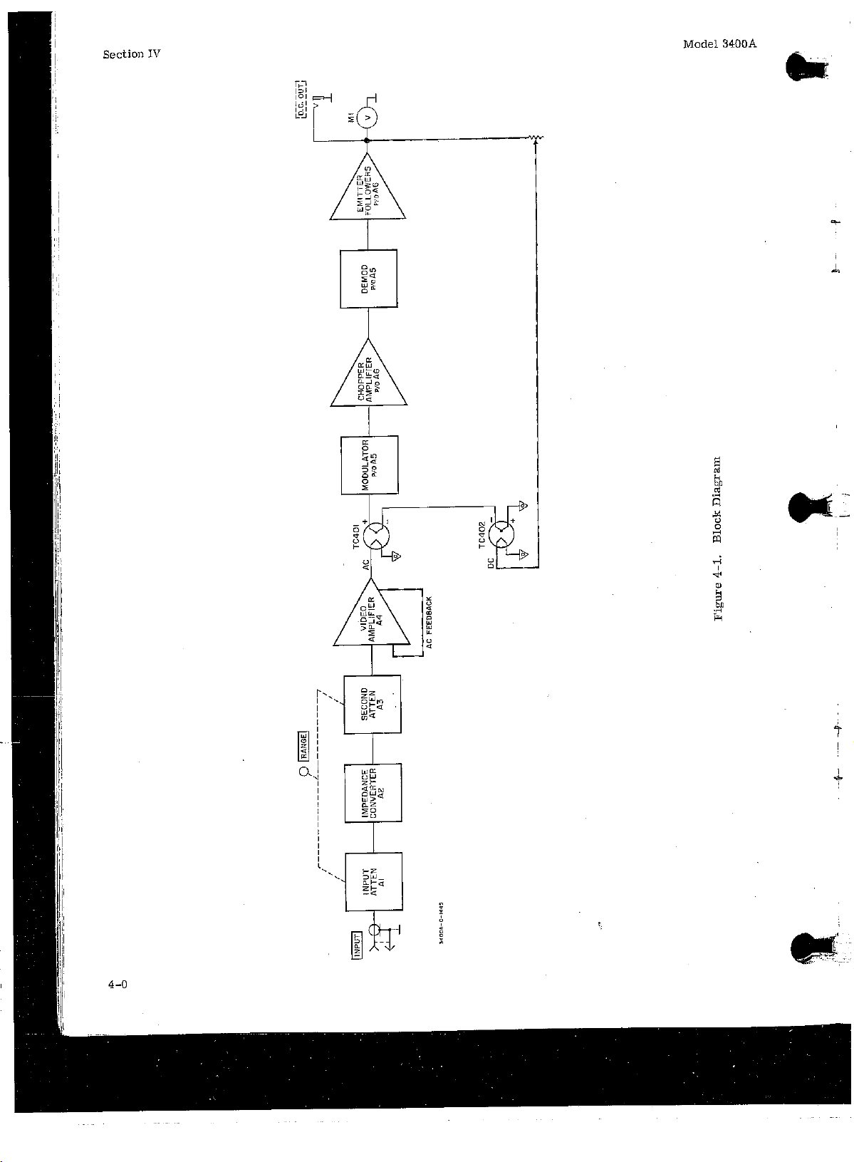
Page 1
Page 2
Page 3
Page 4
Page 5
Page 6
Page 7
Page 8
Page 9
Page 10
Page 11
Page 12
Page 13
Page 14
Page 15
Page 16
Page 17
Page 18
Page 19
Page 20
Page 21
Page 22
Page 23
Page 24
Page 25
Page 26
Page 27
Page 28
Page 29
Page 30
Page 31

Page 32

Page 33

Page 34

Page 35

Page 36

Page 37

Page 38

Page 39

Page 40

Page 41

Page 42
Page 43

Page 44
Page 45

Page 46
Page 47

Page 48

Page 49

Page 50

Page 51

Page 52

Page 53

Page 54

Page 55

Page 56

Page 57

*TB 9-6625-011-35
SUPERSEDED COPY DATED 30 AUGUST 1982
DEPARTMENT OF THE ARMY TECHNICAL BULLETIN
CALIBRATION PROCEDURE FOR
TRUE RMS VOLTMETER ME-318/U
(HEWLETT-PACKARD, MODEL 3400A)
Headquarters, Department of the Army, Washington, DC
29 May 1992
Approved for public release; distribution is unlimited.
♦♦REPORTING OF ERRORS♦♦
You can help improve this publication by calling attention to errors and by
recommending improvements and stating your reasons for the
recommendations. Your letter or DA Form 2028, Recommended Changes to
Publications, should be mailed directly to Commander, U. S. Army Aviation and
Missile Command, ATTN: AMSAM-TMD-EP, Redstone Arsenal, AL 35898-5000.
FAX to DSN 788-2313 (commercial 256-842-2313). A reply will be furnished
directly to you.
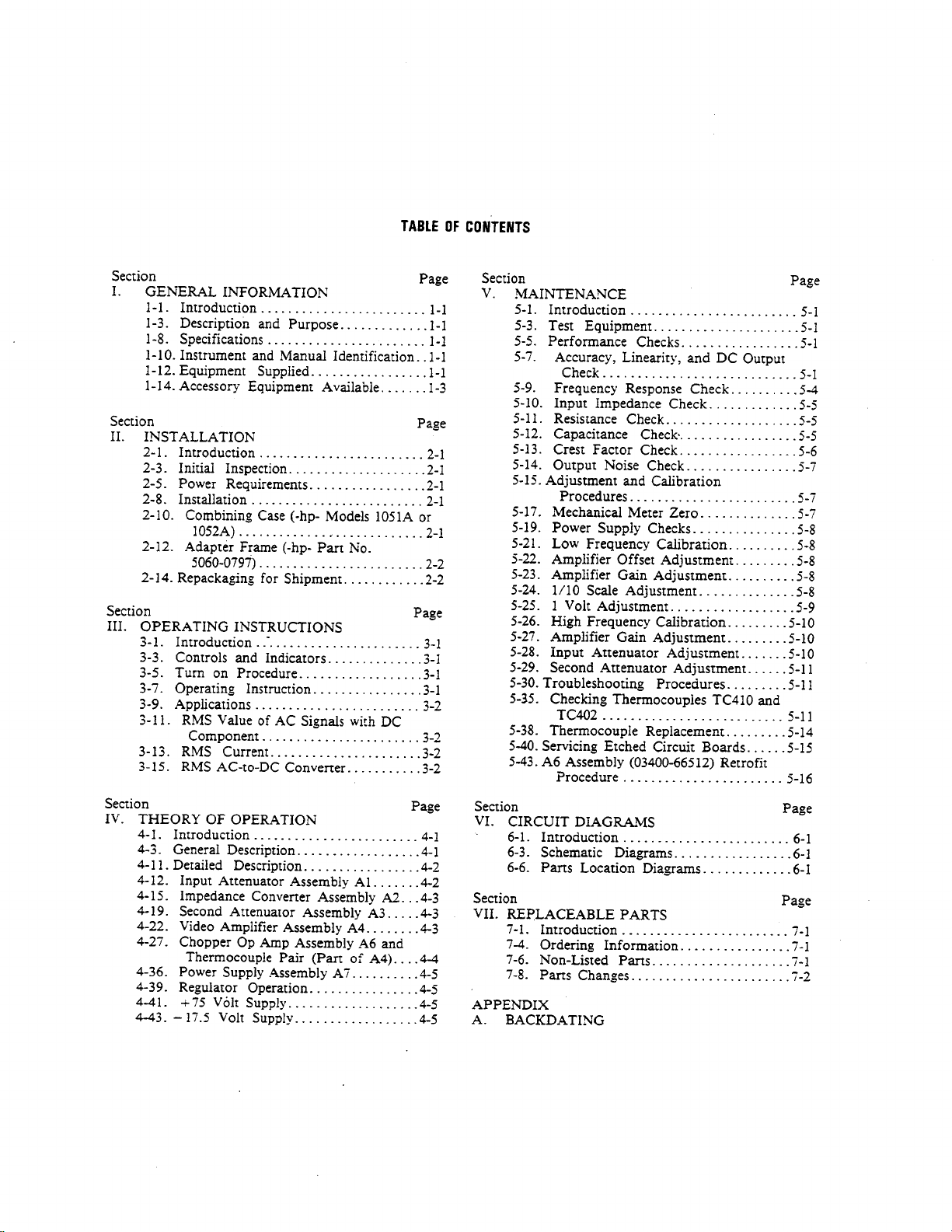
SECTION I INDENTIFICATION AND DESCRIPTION
Test instrument identification.............................. 1 2
Forms, records, and reports.................................. 2 2
Calibration description......................................... 3 2
II EQUIPMENT REQUIREMENTS
Equipment required.............................................. 4 2
Accessories required............................................. 5 3
III CALIBRATION PROCESS
Preliminary instructions ...................................... 6 4
Equipment setup................................................... 7 5
Voltage accuracy................................................... 8 5
Final procedure..................................................... 9 10
____________
*This bulletin supersedes TB 9-6625-011-35, dated 30 August 1982, including all changes.
Paragraph Page
Page 58

TB 9-6625-011-35
SECTION I
IDENTIFICATION AND DESCRIPTION
1. Test Instrument Identification. This bulletin provides instructions for the
calibration of True RMS Voltmeter ME-318/U (Hewlett-Packard, Model 3400A). The
manufacturer's manuals were used as the prime data sources in compiling these
instructions. The equipment being calibrated will be referred to as the TI (test instrument)
throughout this bulletin.
a. Model Variations. Variations among models are described in text.
b. Time and Technique. The time required for this calibration is approximately 1.5
hours, using the dc and low frequency technique.
2. Forms, Records, and Reports. Forms, records, and reports required for calibration
personnel at all levels are prescribed by TB 750-25.
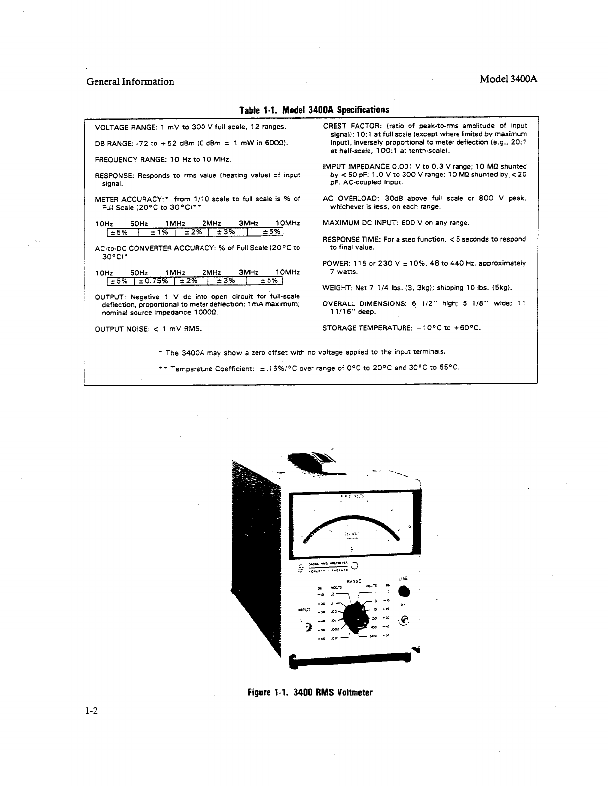
3. Calibration Description. TI parameters and performance specifications which
pertain to this calibration are listed in table I.
Table 1. Calibration Description
Test instrument parameters Performance specifications
Ac voltage Range: 1.0 mV to 300 V rms in 12 ranges
Frequency: 10 Hz to 10 MHz
Accuracy: ±(%) FS
Frequency
10 to 50 Hz................ 5.0
50 Hz to 1.0 MHz............. 1.0
1.0 to 2.0 MHz............. 2.0
2.0 to 3.0 MHz............. 3.0
3.0 to 10 MHz............. 5.0
SECTION II
EQUIPMENT REQUIREMENTS
4. Equipment Required. Table 2 identifies the specific equipment to be used in this
calibration procedure. This equipment is issued with Secondary Transfer Calibration
Standards Set AN/GSM-286. Alternate items may be used by the calibrating activity. The
items selected must be verified to perform satisfactorily prior to use and must bear evidence
of current calibration. The equipment must meet or exceed the minimum use specifications
listed in table 2. The accuracies listed in table 2 provide a four-to-one ratio between the
standard and TI.
5. Accessories Required. The accessories required for this calibration are common
usage accessories issued as indicated in paragraph 4 above and are not listed in this
calibration procedure.
2
Page 59

Table 2. Minimum Specifications of Equipment Required
Common name Minimum use specifications
CALIBRATOR
DIGITAL
MULTIMETER
Ac voltage:
Range: 10 mV to 300 V
Frequency: 400 Hz and 1 kHz
Accuracy: ±.25%
Wideband voltage:
Voltage: 900 µV to 0.9 V
Frequency: 20 Hz to 10 MHz
(1 kHz reference)
Amplitude flatness: ±(%)
Frequency: 20 Hz 1.25
400 Hz to 1 MHz 0.25
2 MHz 0.50
3 MHz 0.75
10 MHz 1.25
Range: -1.0 V dc
Accuracy: ±.25%
TB 9-6625-011-35
Manufacturer and model
(part number)
John Fluke, Model 5700A/CT w/option 003
(p/o MIS-35947) w/Power Amplifier, John
Fluke, Model 5215A/CT (5215A/CT),
w/Ac Divider, John Fluke, Model 7405A4207 (7405A-4207)
John Fluke, Model 8506A/CT (p/o MIS-
35947)
SECTION III
CALIBRATION PROCESS
6. Preliminary Instructions
a. The instructions outlined in paragraphs 6 and 7 are preparatory to the calibration
process. Personnel should become familiar with the entire bulletin before beginning the
calibration.
b. Items of equipment used in this procedure are referenced within the text by common
name as listed in table 2.
c. Unless otherwise specified, verify the results of each test and, whenever the test
requirement is not met, take corrective action before continuing with the calibration.
Additional maintenance information is contained in the manufacturers' manuals for this
TI.
d. Unless otherwise specified, all controls and control settings refer to the TI.
3
Page 60

TB 9-6625-011-35
7. Equipment Setup
WARNING
HIGH VOLTAGE is used or exposed during the performance of
this calibration. DEATH ON CONTACT may result if
personnel fail to observe safety precautions. REDUCE
OUTPUT(S) to minimum after each step within the
performance check where applicable.
a. Remove protective cover from TI only when necessary to make adjustments.
Replace cover after completing the adjustments; then repeat the check.
b. Zero meter using front panel adjustment and set RANGE switch to 300 VOLTS.
c Connect to an appropriate ac voltage source and press LINE switch to ON. Allow at
least 30 minutes for warmup.
8. Voltage Accuracy
a. Performance Check
(1) Connect calibrator OUTPUT to TI INPUT terminal and connect digital
multimeter to TI rear panel DC OUT terminal.
(2) Set TI RANGE switch to .01 VOLTS and set calibrator for a 10 mV, 400 Hz
output. If digital multimeter does not indicate -1.0 (±.01) V, perform b (1) and (2) below.
(3) Connect calibrator OUTPUT to TI INPUT terminal.
(4) Set calibrator for a 10 mV, 400 Hz output, then adjust calibrator for a TI
indication of 1 on the 0-to-1 scale. Calibrator Error display will be < ±1.0%; if not, perform
b(3) through (7) below.
(5) Set TI RANGE switch to 1 VOLTS and set calibrator for a 1.0 V, 400 Hz
output, then adjust calibrator for a TI indication of 1 on the 0-to-1 scale. Calibrator Error
display will be < ±1.0%; if not, perform b(8) below.
(6) Reset calibrator.
(7) Connect ac divider INPUT (p/o calibrator) to calibrator OUTPUT terminals and
ac divider OUTPUT to TI INPUT terminal.
(8) Set TI RANGE switch and calibrator initial output as indicated in table 3.
Adjust calibrator for the TI meter indication specified. Calibrator Error display will
indicate within the specified limits.
4
Page 61

TB 9-6625-011-35
(9) Connect TI INPUT to calibrator WIDEBAND output and press calibrator W
BND pushbutton.
(10) Set TI RANGE switch to .001 VOLTS.
(11) Set calibrator for an initial 900 µV, 1 kHz, wideband output. Adjust calibrator
for a TI indication equal to value recorded in table 3 (.0009 V) to establish a 1 kHz
reference. Press calibrator NEW REF pushbutton.
(12) Set calibrator frequency to 20 Hz, then readjust amplitude for TI reference
established in (11) above. Calibrator Error display indication will be < ±5.6%.
(13) Repeat technique of (12) above for remaining frequencies listed for the .001
VOLTS RANGE switch settings in table 4. Calibrator Error display will be within
specified limits; if not, perform b(9) through (11) below.
(14) Repeat technique of (10) through (13) above for TI RANGE switch settings and
calibrator initial voltage listed in table 4. Calibrator Error display indication will be within
the limits specified; if not, perform b(12) through (14) below for 1 VOLTS RANGE switch
setting and (15) through (17) for .3 VOLTS RANGE switch setting.
Table 3. Range Accuracy
Test instrument Calibrator
RANGE
switch settings
(VOLTS)
.001 1 --- 1.0 V 1.0 kHz 1.0
.003 --- 3 3.0 V 1.0 kHz 1.0
.03 --- 3 30 mV 1.0 kHz 1.0
.1 1 --- 100 mV 1.0 kHz 1.0
.3 --- 3 0.3 V 1.0 kHz 1.0
1 1 --- 1.0 V 1.0 kHz 1.0
1 .8 --- 0.8 V 1.0 kHz 1.25
1 .6 --- 0.6 V 1.0 kHz 1.7
1 .4 --- 0.4 V 1.0 kHz 2.5
1 .2 --- 200 mV 1.0 kHz 5.0
3 --- 3 3.0 V 1.0 kHz 1.0
10 1 --- 10 V 1.0 kHz 1.0
30 --- 3 30 V 1.0 kHz 1.0
100 1 --- 100 V 1.0 kHz 1.0
1
2
b(15) below.
3
below.
300 --- 3 300 V 1.0 kHz 1.0
After performing this check, set calibrator for a .9 V, 1 kHz output and record TI indication (.0009 V) for use in b(9) below.
After performing this check, set calibrator for a 0.3 V. 1 kHz output and record TI indication (on the 0-to-1 scale) for used in
After performing this check, set calibrator for a .9 V, 1 kHz output and record TI indication for use in b(l2)
Meter indication scale Initial output
0-to-1 0-to-3 Voltage Frequency
Reset calibrator and remove ac divider from setup
ERROR
indications
< ± (%)
display
1
2
3
5
Page 62

TB 9-6625-011-35
Table 4. Frequency Response
Test instrument Calibrator
RANGE
switch settings Initial
voltage Frequency
.001 --- 400 Hz 1.1
.001 --- 10 kHz 1.1
.001 --- 50 kHz 1.1
.001 --- 100 kHz 1.1
.001 --- 500 kHz 1.1
.001 --- 1.0 MHz 1.1
.001 --- 2.0 MHz 2.2
.001 --- 3.0 MHz 3.3
.001 --- 10 MHz 5.6
1 0.9 V 1.0 kHz N/A
1 --- 20 Hz 5.6
1 --- 10 kHz 1.1
1 --- 50 kHz 1.1
1 --- 100 kHz 1.1
1 --- 500 kHz 1.1
1 --- 1.0 MHz 1.1
1 --- 2.0 MHz 2.2
1 --- 3.0 MHz 3.3
1 --- 10 MHz 5.6
.3 0.3 V 1.0 kHz N/A
.3 --- 20 Hz 5.0
.3 --- 400 Hz 1.0
.3 --- 10 kHz 1.0
.3 ... 50 kHz 1.0
.3 --- 100 kHz 1.0
.3 --- 500 kHz 1.0
.3 --- 1.0 MHz 1.0
.3 --- 2.0 MHz 2.0
.3 --- 3.0 MHz 3.0
.3 --- 10 MHz 5.0
Output
Error display limits
±(%)
b. Adjustments
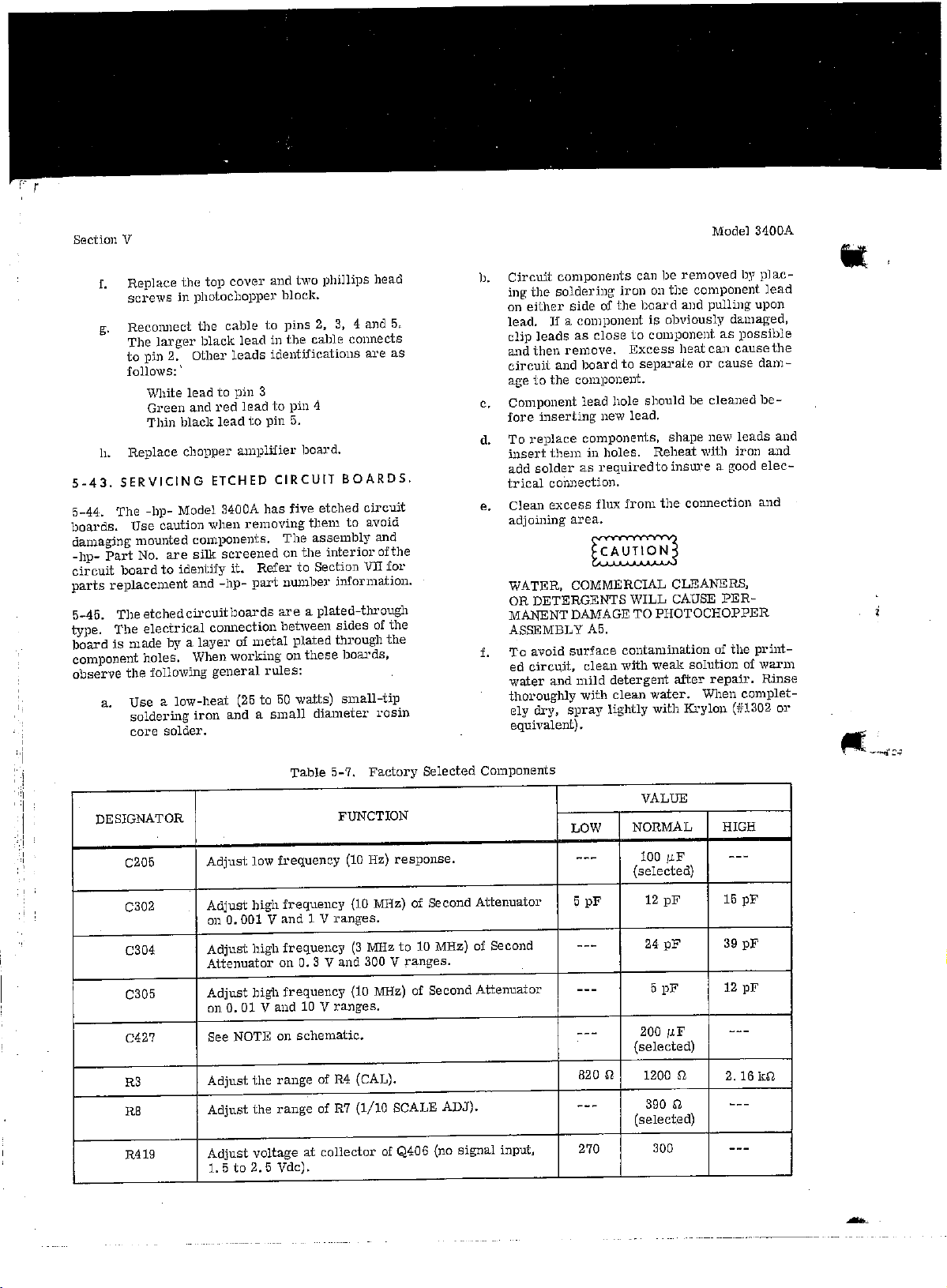
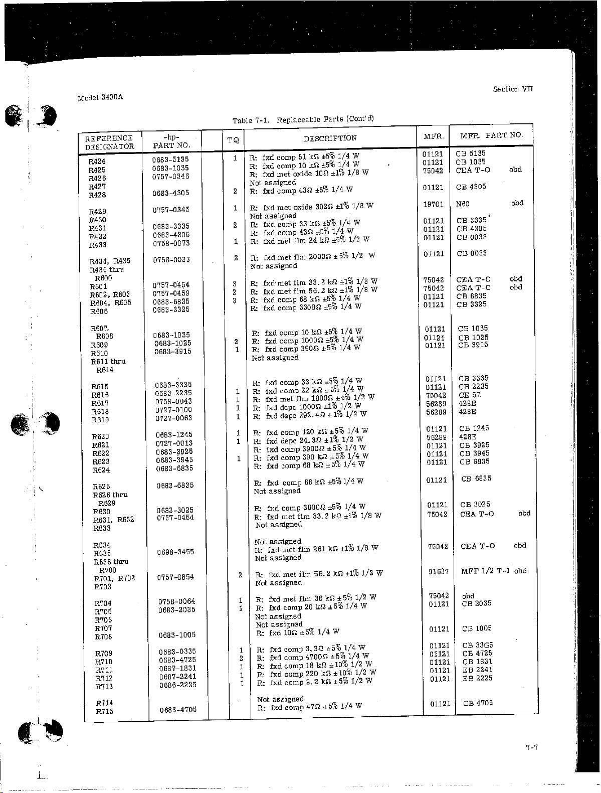
(1) Adjust R4 (R627 for TIs with amplifier board A6, P/N 03400-66512) (fig.1) until
digital multimeter indicates -1.00 V.
(2) If necessary, adjust R6 (fig. 1) for full scale indication on TI.
(3) Set calibrator for a 10 mV, 400 Hz output. Adjust R6 (fig.1) until TI indicates
full scale (R).
(4) Set RANGE switch to .1 VOLTS.
6
Page 63

(5) Adjust R7 (R626 for TIs with amplifier board A6, P/N 03400-66512) (fig. 1) until
TI indicates 0.01 V (1 /10 scale) (R).
(6) Set RANGE switch to .01 VOLTS.
(7) Repeat (3) through (6) above until no further adjustment is necessary.
(8) Set calibrator for a 1.0 V, 400 Hz output. Adjust R104 (fig. 1) until TI indicates
1 (R).
(9) Set calibrator for an initial 900 µV 1 kHz wideband output, then adjust for the
TI indication record for table 3 (.0009 V).
(10) Press calibrator NEW REF pushbutton, then set frequency to 10 MHz. Adjust
C405 (fig. 1) for the 1 kHz reference established b(9) above (R).
(11) Vary calibrator frequency between 3 and 10 MHz and if required, readjust C405
(fig. 1) for best in-tolerance condition.
TB 9-6625-011-35
(12) Set calibrator for an initial 0.9 V, 1 kHz wideband output, then adjust for the TI
indication recorded for table 3 (0.9 V).
(13) Press calibrator NEW REF pushbutton, then set frequency to 100 kHz. Adjust
C102 (fig. 1) for the 1 kHz reference established in b(12) above (R).
(14) Vary calibrator frequency between 100 kHz and 10 MHz and, if required,
readjust C102 (fig. 1) for best intolerance condition.
(15) Set calibrator for an initial 0.3 V, 1 kHz wideband output, then adjust for the TI
indication recorded for table 3 (0.3 V).
(16) Press calibrator NEW REF pushbutton, then set frequency to 3.0 MHz.).
Adjust C303 (fig. 1) for the 1 kHz reference established in b(l5) above (R).
(17) Vary calibrator frequency between 3 and 10 MHz and, if required, readjust C303
(fig. 1) for best in-tolerance condition.
7
Page 64

TB 9-6625-011-35
9. Final Procedure
a. Deenergize and disconnect all equipment.
b. Annotate and affix DA Label/Form in accordance with TB 750-25.
8
Page 65

TB 9-6625-011-35
By Order of the Secretary of the Army:
GORDON R. SULLIVAN
General, United States Army
Chief of Staff
01527
Distribution:
To be distributed in accordance with DA Form 12-34-E, Block No. 2091, requirements
for calibration procedure TB 9-6625-011-35.
US GOVERNMENT PRINTING OFFICE: 1992 - 631-006/60238
PIN NO: 015188-000
Page 66

Errata
3400A Operating & Service
Manual
03400-90013
August 1984
Title & Document Type:
Manual Part Number:
Revision Date:
HP References in this Manual
This manual may contain references to HP or Hewlett-Packard. Please note that HewlettPackard's former test and measurement, semiconductor products and chemical analysis
businesses are now part of Agilent Technologies. We have made no changes to this
manual copy. The HP XXXX referred to in this document is now the Agilent XXXX.
For example, model number HP8648A is now model number Agilent 8648A.
About this Manual
We’ve added this manual to the Agilent website in an effort to help you support your
product. This manual provides the best information we could find. It may be incomplete
or contain dated information, and the scan quality may not be idea l. If we find a better
copy in the future, we will add it to the Agilent website.
Support for Your Product
Agilent no longer sells or supports this product. You will find any other available
product information on the Agilent Test & Measurement website:
www.tm.agilent.com
Search for the model number of this product, and the resulting product page will guide
you to any available information. Our service centers may be able to perform calibration
if no repair parts are needed, but no other support from Agilent is available.
Page 67

Page 68

Page 69

Page 70

Page 71

Page 72

Page 73

Page 74

Page 75
Page 76

Page 77

Page 78
Page 79

Page 80

Page 81

Page 82

Page 83

Page 84

Page 85

Page 86

Page 87

Page 88

Page 89

Page 90

Page 91

Page 92

Page 93

Page 94

Page 95

Page 96

Page 97

Page 98

Page 99

Page 100

 Loading...