

Page 1

HP LaserJet 3390/3392 All-in-One
Service Manual
Page 2

Page 3

HP LaserJet 3390/3392 All-in-One
Service Manual
Page 4

Copyright information
Safety information
Trademark credits
© 2005 Copyright Hewlett-Packard
Development Company, L.P.
Reproduction, adaptation, or translation
without prior written permission is prohibited,
except as allowed under the copyright laws.
The information contained herein is subject
to change without notice.
The only warranties for HP products and
services are set forth in the express warranty
statements accompanying such products
and services. Nothing herein should be
construed as constituting an additional
warranty. HP shall not be liable for technical
or editorial errors or omissions contained
herein.
Part number Q6500-90901
Edition 2, 10/2005
WARNING!
Potential Shock Hazard
Always follow basic safety precautions when
using the all-in-one to reduce risk of injury
from fire or electric shock.
Read and understand all instructions in the
user guide.
Observe all warnings and instructions
marked on the all-in-one.
Use only a grounded electrical outlet when
connecting the all-in-one to a power source.
If you do not know whether the outlet is
grounded, check with a qualified electrician.
Do not touch the contacts on the end of any
of the sockets on the all-in-one. Replace
damaged cords immediately.
Unplug the all-in-one from wall outlets before
cleaning.
Do not install or use the all-in-one near water
or when you are wet.
Install the product securely on a stable
surface.
Microsoft® and Windows® are U.S.
registered trademarks of Microsoft
Corporation.
Linux is a U.S. registered trademark of Linus
Torvalds.
UNIX® is a registered trademark of The
Open Group.
PostScript® is a trademark of Adobe
Systems Incorporated.
Energy Star® and the Energy Star logo® are
U.S. registered marks of the United States
Environmental Protection Agency.
Install the all-in-one in a protected location
where no one can step on or trip over the
power cord and where the power cord will not
be damaged.
If the all-in-one does not operate normally,
see the online user guide.
Refer all servicing questions to qualified
personnel.
Information regarding FCC Class B, Parts 15
and 68 requirements can be found in the user
guide.
Page 5

FCC Regulations
This equipment has been tested and found
to comply with the limits for a Class B digital
device, pursuant to Part 15 of the FCC rules.
These limits are designed to provide
reasonable protection against harmful
interference in a residential installation. This
equipment generates, uses, and can radiate
radio frequency energy. If this equipment is
not installed and used in accordance with the
instructions, it may cause harmful
interference to radio communications.
However, there is no guarantee that
interference will not occur in a particular
installation. If this equipment does cause
harmful interference to radio or television
reception, which can be determined by
turning the equipment off and on, the user is
encouraged to try to correct the interference
by one or more of the following measures:
Reorient or relocate the receiving antenna.
Increase separation between equipment and
receiver.
Connect equipment to an outlet on a circuit
different from that to which the receiver is
located.
Consult your dealer or an experienced radio/
TV technician.
Any changes or modifications to the printer
that are not expressly approved by HP could
void the user's authority to operate this
equipment.
Use of a shielded interface cable is required
to comply with the Class B limits of Part 15 of
FCC rules.
This equipment complies with FCC rules,
Parts 15 and 68. On the back of this
equipment is a label that contains, among
other information, the FCC registration
number and ringer equivalence number
(REN) for this equipment. If requested, this
information must be provided to the
telephone company. The REN is used to
determine the quantity of devices which may
be connected to the telephone line.
Excessive RENs on the telephone line may
result in the devices not ringing in response
to an incoming call. In most, but not all, areas,
the sum of the RENs should not exceed five
(5.0). To be certain of the number of devices
that may be connected to the line, as
determined by the total RENs, contact the
telephone company to determine the
maximum REN for the calling area.
This equipment is designed to be connected
to the telephone network or premises wiring
using a compatible modular jack which is
Part 68 compliant. This equipment cannot be
used on telephone company-provided coin
service. Connection to Party Line Service is
subject to state tariffs. If this equipment
causes harm to the telephone network, the
telephone company will notify you in
advance that temporary discontinuance of
service may be required. If advance notice is
not practical, the telephone company will
notify the customer as soon as possible.
Also, you will be advised of your right to file
a complaint with the FCC if you believe it is
necessary. The telephone company may
make changes in its facilities, equipment,
operations, or procedures that could affect
the operation of the equipment. If this
happens, the telephone company will
provide advance notice in order for you to
make the necessary modifications in order to
maintain uninterrupted service. If trouble is
experienced with this equipment, please see
the numbers in the front of this manual for
repair and (or) warranty information. If the
trouble is causing harm to the telephone
network, the telephone company may
request you remove the equipment from the
network until the problem is resolved. The
following repairs can be done by the
customer: Replace any original equipment
that came with the device. This includes the
print cartridge, the supports for trays and
bins, the power cord, and the telephone cord.
It is recommended that the customer install
an ac surge arrestor in the ac outlet to which
this device is connected. This is to avoid
damage to the equipment caused by local
lightning strikes and other electrical surges.
See the electronic user guide for more
regulatory information.
This equipment uses the following USOC
jacks: RJ11C.
An FCC-compliant telephone cord and
modular plug is provided with this equipment.
Page 6

Page 7

Table of contents
1 Product information
Quick access to all-in-one information ................................................................................................. 2
All-in-one configurations ....................................................................................................................... 3
All-in-one features ................................................................................................................................ 5
Product walkaround .............................................................................................................................. 7
HP LaserJet 3390/3392 all-in-one ....................................................................................... 7
Interface ports ...................................................................................................................... 9
Control panel ....................................................................................................................... 9
Model and serial numbers .................................................................................................................. 10
Software description ........................................................................................................................... 11
Supported drivers .............................................................................................................. 11
Additional drivers ............................................................................................................... 11
Software installation ........................................................................................................................... 12
Typical installation ............................................................................................................. 12
Minimum installation .......................................................................................................... 12
Software for Windows ........................................................................................................................ 13
Software components for Windows ................................................................................... 13
HP ToolboxFX ................................................................................................... 13
Embedded Web server (EWS) .......................................................................... 13
Software for Macintosh ....................................................................................................................... 14
HP Director ........................................................................................................................ 14
Macintosh Configure Device (Mac OS X V10.3 and Mac OS X V10.4) ............................. 14
PDEs (Mac OS X V10.3 and Mac OS X V10.4) ................................................................. 15
Uninstalling software .......................................................................................................................... 16
Windows ............................................................................................................................ 16
Macintosh .......................................................................................................................... 16
Media specifications ........................................................................................................................... 17
Supported media weights and sizes .................................................................................. 17
Media to avoid ................................................................................................................... 18
Media that can damage the all-in-one ............................................................................... 19
2 Installation
Operating environment ....................................................................................................................... 22
Minimum system requirements .......................................................................................... 23
Unpacking .......................................................................................................................................... 24
Installing input devices ....................................................................................................................... 25
ADF input tray .................................................................................................................... 25
250-sheet input tray (tray 3) ............................................................................................... 26
Installing the control-panel faceplate .................................................................................................. 27
ENWW v
Page 8

Loading media .................................................................................................................................... 28
Installing accessories ......................................................................................................................... 32
3 Maintenance
Managing supplies ............................................................................................................................. 36
Cleaning the all-in-one ....................................................................................................................... 53
Managing the all-in-one ...................................................................................................................... 65
Using the HP ToolboxFX .................................................................................................................... 68
Loading documents to fax, copy, or scan .......................................................................... 28
Loading the single-sheet priority input slot (tray 1) ............................................................ 30
Loading tray 2 or optional tray 3 ........................................................................................ 30
Removing and replacing a DIMM ...................................................................................... 32
Life expectancies of supplies and the all-in-one ................................................................ 36
Ordering supplies ............................................................................................................... 36
Storing print cartridges ....................................................................................................... 37
Replacing and recycling supplies ...................................................................................... 37
Replacing the print cartridge .............................................................................................. 39
Replacing the staple cassette ............................................................................................ 42
Replacing the tray 2 pickup roller ...................................................................................... 44
Replacing the tray 2 and optional tray 3 separation pad ................................................... 49
HP policy on non-HP supplies ........................................................................................... 52
Resetting the all-in-one for non-HP supplies ..................................................... 52
HP fraud hotline ................................................................................................................. 52
To clean the exterior .......................................................................................................... 53
Cleaning the flatbed scanner glass .................................................................................... 53
Cleaning the scanner-cover backing ................................................................................. 55
Cleaning the tray 2 pickup roller ....................................................................................... 56
Cleaning the ADF pickup-roller assembly .......................................................................... 60
Cleaning the print path ....................................................................................................... 63
Information pages .............................................................................................................. 65
To view the HP ToolboxFX ................................................................................................ 68
Status ................................................................................................................................. 68
Event log ........................................................................................................... 69
Alerts .................................................................................................................................. 69
Set up status alerts ........................................................................................... 69
Set up e-mail alerts ........................................................................................... 69
Fax ..................................................................................................................................... 70
Fax tasks ........................................................................................................... 70
Fax phone book ................................................................................................ 70
Fax send log ...................................................................................................... 73
Fax receive log .................................................................................................. 73
Help (Documentation) ........................................................................................................ 73
System settings ................................................................................................................. 74
Device information ............................................................................................ 74
Paper handling .................................................................................................. 75
Print quality ....................................................................................................... 75
Paper types ....................................................................................................... 75
System setup .................................................................................................... 76
Service .............................................................................................................. 76
Device Polling ................................................................................................... 76
vi ENWW
Page 9

Print settings ...................................................................................................................... 76
Network settings ................................................................................................................ 77
Using Macintosh Configure Device (Mac OS X V10.3 and Mac OS X V10.4) ................................... 78
Understanding the Embedded Web server ........................................................................................ 79
Features ............................................................................................................................. 79
4 Theory of operation
Basic operation ................................................................................................................................... 82
Sequence of operation for the base unit ............................................................................ 82
Scanner and ADF functions and operation ........................................................................................ 84
Scanner functions ............................................................................................................. 84
Scanner operation ............................................................................................................. 85
ADF operation .................................................................................................................... 85
ADF paper path and ADF sensors ..................................................................................... 86
ADF jam detection ............................................................................................................. 87
Internal components (base unit) ......................................................................................................... 88
Engine control system ........................................................................................................................ 90
Laser/scanner system ........................................................................................................................ 92
Pickup/feed/delivery system ............................................................................................................... 93
Image-formation system ..................................................................................................................... 95
Fax functions and operation ............................................................................................................... 99
Computer and network security features ........................................................................... 99
PSTN operation ................................................................................................................. 99
To receive faxes when you hear fax tones ...................................................................... 100
Distinctive ring function .................................................................................................... 100
Faxing with Voice over IP services .................................................................................. 101
The fax subsystem ........................................................................................................... 101
Formatter in the fax subsystem ....................................................................................... 101
LIU in the fax subsystem ................................................................................................. 102
Fax page storage in flash memory .................................................................................. 105
Printing .............................................................................................................. 76
PCL 5e .............................................................................................................. 77
PostScript .......................................................................................................... 77
Safety isolation ................................................................................................ 102
Safety-protection circuitry ................................................................................ 102
Data path ......................................................................................................... 103
Hook state ....................................................................................................... 103
Downstream current detection ........................................................................ 103
Hook switch control ......................................................................................... 104
Ring detect ...................................................................................................... 104
Line current control ......................................................................................... 104
Billing- (metering-) tone filters ......................................................................... 104
Stored fax pages ............................................................................................. 105
Advantages of flash memory storage ............................................................. 105
5 Removal and replacement
Introduction ....................................................................................................................................... 108
Removal and replacement strategy ................................................................................ 108
Electrostatic discharge ..................................................................................................... 108
User-replaceable parts .................................................................................................... 109
ENWW vii
Page 10

Required tools ................................................................................................................. 109
Before performing service ................................................................................................ 109
After performing service ................................................................................................... 110
Post-service tests ............................................................................................................ 110
Test 1 (print-quality test) ................................................................................. 110
Test 2 (copy-quality test) ................................................................................. 110
Test 3 (fax-quality test) .................................................................................... 111
Parts removal order ......................................................................................................... 112
Remove the print cartridge .............................................................................................. 113
External panels, covers, and doors .................................................................................................. 114
Right cover ....................................................................................................................... 114
Left cover ......................................................................................................................... 116
Print-cartridge door .......................................................................................................... 118
Rear cover ....................................................................................................................... 120
Top cover ......................................................................................................................... 122
Replacing the ADF pickup-roller assembly ...................................................................................... 124
ADF assembly .................................................................................................................................. 127
Scanner/ADF assembly .................................................................................................................... 129
Bezel and control panel .................................................................................................................... 131
Internal assemblies .......................................................................................................................... 134
Convenience-stapler assembly (HP LaserJet 3392 only) ................................................ 134
Convenience-stapler power supply (HP LaserJet 3392 only) .......................................... 136
Convenience-stapler ac inlet cable (HP LaserJet 3392 only) .......................................... 138
Convenience-stapler power supply bracket and strap (HP LaserJet 3392 only) ............. 139
Speaker ........................................................................................................................... 140
Power-switch PCA ........................................................................................................... 142
Formatter ......................................................................................................................... 143
Duplex assembly ............................................................................................................. 146
Laser/scanner .................................................................................................................. 148
Memory-tag-reader assembly .......................................................................................... 150
Fuser ................................................................................................................................ 152
Fan .................................................................................................................. 152
Duplex-drive gears .......................................................................................... 154
Duplex solenoid ............................................................................................... 155
Fuser ................................................................................................................................ 157
Interlock assembly ........................................................................................................... 163
ECU ................................................................................................................................. 164
Main motor ....................................................................................................................... 169
Pickup-and-feed assemblies ............................................................................................ 171
Transfer roller .................................................................................................. 171
Registration-roller assembly ............................................................................................ 172
Main gear assembly and tray 2 pickup solenoid .............................................................. 173
6 Troubleshooting
Troubleshooting process .................................................................................................................. 178
Troubleshooting checklist ................................................................................................ 178
Jams ................................................................................................................................................. 181
Causes of jams ................................................................................................................ 181
Tips to avoid jams ............................................................................................................ 182
Where to look for jams ..................................................................................................... 182
viii ENWW
Page 11

Jams in the print-cartridge area ....................................................................................... 183
Jams in the trays .............................................................................................................. 186
Jams in the output bin ...................................................................................................... 191
Jams in the straight-through output path ......................................................................... 192
Jams in the duplex path ................................................................................................... 194
Jams in the ADF .............................................................................................................. 199
Jams in the convenience stapler (HP LaserJet 3392 only) .............................................. 204
Control-panel messages .................................................................................................................. 207
Alerts and warning messages .......................................................................................... 207
Critical-error message-tables ........................................................................................... 212
Print problems .................................................................................................................................. 215
Print-quality problems ...................................................................................................... 215
Improving print quality ..................................................................................... 215
Understanding print-quality settings ............................................... 215
To temporarily change print-quality settings .................. 215
To change print-quality settings for all future jobs .......... 216
Identifying and correcting print defects ........................................................... 217
Print-quality checklist ...................................................................... 217
General print-quality issues ............................................................ 217
Media-handling problems ................................................................................................ 222
Print-media guidelines ..................................................................................... 222
Solving print-media problems .......................................................................... 222
Performance problems .................................................................................................... 224
Scan problems ................................................................................................................................. 225
Solving scanned-image problems .................................................................................... 225
Scan-quality problems ..................................................................................................... 227
Preventing problems ....................................................................................... 227
Solving scan-quality problems ........................................................................ 227
Copy problems ................................................................................................................................. 228
Preventing problems ........................................................................................................ 228
Image problems ............................................................................................................... 228
Media-handling problems ................................................................................................ 229
Performance problems .................................................................................................... 231
Fax troubleshooting .......................................................................................................................... 232
General fax troubleshooting ............................................................................................. 232
Problems receiving faxes ................................................................................................. 234
Problems sending faxes .................................................................................................. 236
Voice-call problems ......................................................................................................... 238
Media-handling problems ................................................................................................ 238
Performance problems .................................................................................................... 239
Control-panel display problems ........................................................................................................ 240
Convenience-stapler problems (HP LaserJet 3392 only) ................................................................. 240
DSL problems ................................................................................................................................... 241
PABX line problems ......................................................................................................... 241
ADF problems .................................................................................................................................. 242
Functional checks ............................................................................................................................. 244
Drum rotation test ............................................................................................................ 244
Engine test ....................................................................................................................... 245
Half self-test functional check .......................................................................................... 246
To perform a half self-test check ..................................................................................... 246
ENWW ix
Page 12

To perform other checks ................................................................................................. 246
Heating element check .................................................................................................... 247
High-voltage contacts check ............................................................................................ 247
To check the print-cartridge contacts ............................................................ 247
To check the high-voltage connector assembly ............................................. 248
Service-mode functions .................................................................................................................... 249
NVRAM initialization ........................................................................................................ 249
Secondary service menu ................................................................................................. 249
Troubleshooting tools ....................................................................................................................... 251
All-in-one pages and reports ............................................................................................ 251
Demo page ...................................................................................................... 251
Configuration page .......................................................................................... 251
Supplies Status page ...................................................................................... 251
Fax reports ....................................................................................................................... 252
Fax activity log ................................................................................................ 252
Fax call report ................................................................................................. 252
Phone book report ........................................................................................... 252
Billing-code report ........................................................................................... 253
HP ToolboxFX ................................................................................................................. 253
To view HP ToolboxFX ................................................................................... 253
Troubleshooting tab ........................................................................................ 253
Service menu .................................................................................................................. 254
Restoring the factory-set defaults ................................................................... 254
Cleaning the paper path .................................................................................. 254
T.30 protocol trace .......................................................................................... 255
Archive print .................................................................................................... 255
Firmware updates and recovery ....................................................................................................... 256
Firmware update by using a flash executable file ............................................................ 256
Firmware-recovery DIMM ................................................................................................ 256
7 Parts
Accessories and ordering information .............................................................................................. 259
Supplies ............................................................................................................................................ 260
Memory ............................................................................................................................................ 260
Cable and interface accessories ...................................................................................................... 260
Paper-handling accessories ............................................................................................................ 261
Scanner/ADF replacement parts ...................................................................................................... 261
Control-panel bezels ........................................................................................................................ 262
Supplementary documentation and support ..................................................................................... 263
Troubleshooting diagrams ................................................................................................................ 266
Repetitive image defects ................................................................................................. 266
Interface connectors ....................................................................................................... 267
Formatter connectors ....................................................................................................... 268
Line interface unit (LIU) ................................................................................................... 269
Solenoids ......................................................................................................................... 270
Switches and sensors ...................................................................................................... 271
Rollers and pads .............................................................................................................. 272
PCAs (base unit) .............................................................................................................. 273
Major components (base unit) ......................................................................................... 274
Scanner and ADF ............................................................................................................ 275
x ENWW
Page 13

Circuit diagram ................................................................................................................. 276
How to use the parts lists and diagrams .......................................................................................... 278
Types of screws ............................................................................................................... 278
Scanner and ADF assemblies .......................................................................................................... 280
Scanner components ....................................................................................................................... 282
ADF components .............................................................................................................................. 284
Convenience stapler components (HP LJ 3392 only) ...................................................................... 286
Formatter, LIU, HP jewel, and nameplate ........................................................................................ 288
External covers and panels .............................................................................................................. 290
Internal components (1 of 4) ............................................................................................................ 292
Internal components (2 of 4) ............................................................................................................ 294
Internal components (3 of 4) ............................................................................................................ 296
Internal components (4 of 4) ............................................................................................................ 298
Engine-controller assembly .............................................................................................................. 300
Main-drive assembly ........................................................................................................................ 302
Duplexing-drive assembly ................................................................................................................ 304
Tray 2 cassette and tray 3 cassette/feeder ...................................................................................... 306
Duplexing assembly ......................................................................................................................... 308
Fuser assembly ................................................................................................................................ 310
Alphabetical parts list ....................................................................................................................... 312
Numerical parts list ........................................................................................................................... 317
Appendix A All-in-one specifications
Physical specifications ..................................................................................................................... 324
Supplies specifications ..................................................................................................................... 324
Performance ..................................................................................................................................... 325
Electrical specifications .................................................................................................................... 327
Power consumption .......................................................................................................................... 327
Environmental specifications ............................................................................................................ 328
Acoustic emissions ........................................................................................................................... 328
Appendix B Warranty information
Hewlett-Packard limited warranty statement .................................................................................... 330
Print Cartridge Limited Warranty Statement ..................................................................................... 331
Extended warranty ........................................................................................................................... 332
Appendix C Regulatory statements
Declaration of conformity (HP LaserJet 3390, 3392, 3055, and 3050) ............................................ 334
Country/region-specific safety statements ....................................................................................... 335
Laser safety statement .................................................................................................... 335
Canadian DOC statement ................................................................................................ 335
Korean EMI statement ..................................................................................................... 335
Finnish laser statement .................................................................................................... 336
Japan power cord statement ........................................................................................... 336
Index ................................................................................................................................................................. 337
ENWW xi
Page 14

xii ENWW
Page 15

List of tables
Table 1-1 All-in-one guides ................................................................................................................................ 2
Table 1-2 All-in-one configurations ..................................................................................................................... 3
Table 1-3 All-in-one features .............................................................................................................................. 5
Table 1-4 Supported printer drivers .................................................................................................................. 11
Table 1-5 Single-sheet priority input slot (tray 1) .............................................................................................. 17
Table 1-6 Tray 2 and optional tray 3 ................................................................................................................ 17
Table 1-7 ADF .................................................................................................................................................. 18
Table 4-1 Sequence of operation ..................................................................................................................... 82
Table 4-2 Power-on sequence ......................................................................................................................... 83
Table 6-1 Alerts and warning messages ....................................................................................................... 207
Table 6-2 Critical-error messages .................................................................................................................. 213
Table 7-1 Control-panel bezels ...................................................................................................................... 262
Table 7-2 Service and training support .......................................................................................................... 263
Table 7-3 User guides .................................................................................................................................... 263
Table 7-4 Getting started guide ...................................................................................................................... 263
Table 7-5 Technical support Web sites .......................................................................................................... 264
Table 7-6 Repetitive image defects ................................................................................................................ 266
Table 7-7 Scanner and ADF assemblies ........................................................................................................ 281
Table 7-8 Scanner components ..................................................................................................................... 283
Table 7-9 ADF components ........................................................................................................................... 285
Table 7-10 Convenience stapler components (HP LJ 3392 only) .................................................................. 287
Table 7-11 Formatter, LIU, HP jewel, and nameplate .................................................................................... 289
Table 7-12 External covers and panels .......................................................................................................... 291
Table 7-13 Internal components (1 of 4) ........................................................................................................ 293
Table 7-14 Internal components (2 of 4) ........................................................................................................ 295
Table 7-15 Internal components (3 of 4) ........................................................................................................ 297
Table 7-16 Internal components (4 of 4) ........................................................................................................ 299
Table 7-17 Engine-controller assembly .......................................................................................................... 301
Table 7-18 Main-drive assembly .................................................................................................................... 303
Table 7-19 Duplexing-drive assembly ............................................................................................................ 305
Table 7-20 Cassette, tray 2 (250-sheet) ......................................................................................................... 307
Table 7-21 Duplexing assembly ..................................................................................................................... 309
Table 7-22 Fuser assembly ............................................................................................................................ 311
Table 7-23 Alphabetical parts list ................................................................................................................... 312
Table 7-24 Numerical parts list ....................................................................................................................... 317
Table A-1 Physical specifications ................................................................................................................... 324
Table A-2 Supplies specifications .................................................................................................................. 324
Table A-3 Performance .................................................................................................................................. 325
Table A-4 Electrical specifications .................................................................................................................. 327
Table A-5 Power consumption (average, in watts) ....................................................................................... 327
ENWW xiii
Page 16

Table A-6 Environmental specifications ........................................................................................................ 328
Table A-7 Acoustic emissions ........................................................................................................................ 328
xiv ENWW
Page 17

List of figures
Figure 1-1 HP LaserJet 3390/3392 all-in-one .................................................................................................... 3
Figure 1-2 Front view ......................................................................................................................................... 7
Figure 1-3 Back view .......................................................................................................................................... 8
Figure 1-4 Interface ports ................................................................................................................................... 9
Figure 1-5 Control panel ..................................................................................................................................... 9
Figure 1-6 HP LaserJet 3390/3392 all-in-one identification label ..................................................................... 10
Figure 2-1 Operating environment ................................................................................................................... 22
Figure 2-2 HP LaserJet 3390/3392 all-in-one package contents ..................................................................... 24
Figure 2-3 Install the ADF input tray ................................................................................................................. 25
Figure 2-4 Install the 250-sheet input tray ........................................................................................................ 26
Figure 2-5 Install the control-panel faceplate ................................................................................................... 27
Figure 2-6 Load a document onto the flatbed scanner .................................................................................... 28
Figure 2-7 Load documents into the ADF (1 of 2) ............................................................................................ 29
Figure 2-8 Load documents into the ADF (2 of 2) ............................................................................................ 29
Figure 2-9 Load the single-sheet priority input slot (tray 1) .............................................................................. 30
Figure 2-10 Loading tray 2 or tray 3 (1 of 3) .................................................................................................... 30
Figure 2-11 Load tray 2 or tray 3 (2 of 3) ......................................................................................................... 31
Figure 2-12 Load tray 2 or tray 3 (3 of 3) ......................................................................................................... 31
Figure 2-13 Removing and replacing a DIMM (1 of 4) ..................................................................................... 32
Figure 2-14 Removing and replacing a DIMM (2 of 4) ..................................................................................... 32
Figure 2-15 Removing and replacing a DIMM (3 of 4) ..................................................................................... 33
Figure 2-16 Removing and replacing a DIMM (4 of 4) ..................................................................................... 33
Figure 3-1 Replacing the print cartridge (1 of 5) .............................................................................................. 39
Figure 3-2 Replacing the print cartridge (2 of 5) .............................................................................................. 39
Figure 3-3 Replacing the print cartridge (3 of 5) .............................................................................................. 40
Figure 3-4 Replacing the print cartridge (4 of 5) .............................................................................................. 40
Figure 3-5 Replacing the print cartridge (5 of 5) .............................................................................................. 41
Figure 3-6 Install the staple cassette (1 of 4) ................................................................................................... 42
Figure 3-7 Install the staple cassette (2 of 4) ................................................................................................... 42
Figure 3-8 Install the staple cassette (3 of 4) ................................................................................................... 43
Figure 3-9 Install the staple cassette (4 of 4) ................................................................................................... 43
Figure 3-10 Replace the tray 2 pickup roller (1 of 7) ........................................................................................ 44
Figure 3-11 Replace the tray 2 pickup roller (2 of 7) ........................................................................................ 45
Figure 3-12 Replace the tray 2 pickup roller (3 of 7) ........................................................................................ 45
Figure 3-13 Replace the tray 2 pickup roller (4 of 7) ........................................................................................ 46
Figure 3-14 Replace the tray 2 pickup roller (5 of 7) ........................................................................................ 46
Figure 3-15 Replace the tray 2 pickup roller (6 of 7) ........................................................................................ 47
Figure 3-16 Replace the tray 2 pickup roller (7 of 7) ........................................................................................ 47
Figure 3-17 Replace the tray 2 or tray 3 separation pad (1 of 6) ..................................................................... 49
Figure 3-18 Replace the tray 2 or tray 3 separation pad (2 of 6) ..................................................................... 49
ENWW xv
Page 18

Figure 3-19 Replace the tray 2 or tray 3 separation pad (3 of 6) ..................................................................... 50
Figure 3-20 Replace the tray 2 or tray 3 separation pad (4 of 6) ..................................................................... 50
Figure 3-21 Replace the tray 2 or tray 3 separation pad (5 of 6) ..................................................................... 51
Figure 3-22 Replace the tray 2 or tray 3 separation pad (6 of 6) ..................................................................... 51
Figure 3-23 Cleaning the scanner glass (1 of 2) .............................................................................................. 53
Figure 3-24 Cleaning the scanner glass (2 of 2) .............................................................................................. 54
Figure 3-25 Cleaning the scanner-cover backing ............................................................................................ 55
Figure 3-26 Cleaning the tray 2 pickup roller (1 of 6) ....................................................................................... 56
Figure 3-27 Cleaning the tray 2 pickup roller (2 of 6) ....................................................................................... 56
Figure 3-28 Cleaning the tray 2 pickup roller (3 of 6) ....................................................................................... 57
Figure 3-29 Cleaning the tray 2 pickup roller (4 of 6) ....................................................................................... 57
Figure 3-30 Cleaning the tray 2 pickup roller (5 of 6) ....................................................................................... 58
Figure 3-31 Cleaning the tray 2 pickup roller (6 of 6) ....................................................................................... 58
Figure 3-32 Cleaning the ADF pickup-roller assembly (1 of 7) ........................................................................ 60
Figure 3-33 Cleaning the ADF pickup-roller assembly (2 of 7) ........................................................................ 60
Figure 3-34 Cleaning the ADF pickup-roller assembly (3 of 7) ........................................................................ 61
Figure 3-35 Cleaning the ADF pickup-roller assembly (4 of 7) ........................................................................ 61
Figure 3-36 Cleaning the ADF pickup-roller assembly (5 of 7) ........................................................................ 62
Figure 3-37 Cleaning the ADF pickup-roller assembly (6 of 7) ........................................................................ 62
Figure 3-38 Cleaning the ADF pickup-roller assembly (7 of 7) ........................................................................ 63
Figure 3-39 Cleaning the print path .................................................................................................................. 63
Figure 4-1 HP LaserJet 3390/3392 all-in-one system block diagram .............................................................. 82
Figure 4-2 Optical system ................................................................................................................................ 84
Figure 4-3 ADF paper path ............................................................................................................................... 86
Figure 4-4 Internal components (base unit) ..................................................................................................... 88
Figure 4-5 Engine control system ..................................................................................................................... 90
Figure 4-6 Engine-control-system circuit diagram ............................................................................................ 91
Figure 4-7 Laser/scanner system ..................................................................................................................... 92
Figure 4-8 Pickup/feed/delivery system ........................................................................................................... 94
Figure 4-9 Image-formation system ................................................................................................................. 95
Figure 4-10 Primary charging ........................................................................................................................... 95
Figure 4-11 Developing .................................................................................................................................... 96
Figure 4-12 Transfer ......................................................................................................................................... 97
Figure 4-13 Separation ..................................................................................................................................... 97
Figure 4-14 Fusing ........................................................................................................................................... 98
Figure 4-15 Drum cleaning ............................................................................................................................... 98
Figure 5-1 Phillips and pozidrive screwdriver comparison ............................................................................. 109
Figure 5-2 Parts-removal tree ........................................................................................................................ 112
Figure 5-3 Remove the print cartridge (1 of 2) ............................................................................................... 113
Figure 5-4 Remove the print cartridge (2 of 2) ............................................................................................... 113
Figure 5-5 Remove the right cover (1 of 4) .................................................................................................... 114
Figure 5-6 Remove the right cover (2 of 4) .................................................................................................... 114
Figure 5-7 Remove the right cover (3 of 4) .................................................................................................... 115
Figure 5-8 Remove the right cover (4 of 4) .................................................................................................... 115
Figure 5-9 Remove the left cover (1 of 3) ....................................................................................................... 116
Figure 5-10 Remove the left cover (2 of 3) ..................................................................................................... 116
Figure 5-11 Remove the left cover (3 of 3) ..................................................................................................... 117
Figure 5-12 Removing the print-cartridge door (1 of 2) .................................................................................. 118
Figure 5-13 Removing the print-cartridge door (2 of 2) .................................................................................. 119
Figure 5-14 Remove the rear cover (1 of 2) ................................................................................................... 120
xvi ENWW
Page 19

Figure 5-15 Remove the rear cover (2 of 2) ................................................................................................... 121
Figure 5-16 Remove the top cover (1 of 3) .................................................................................................... 122
Figure 5-17 Remove the top cover (2 of 3) .................................................................................................... 122
Figure 5-18 Remove the top cover (3 of 3) .................................................................................................... 123
Figure 5-19 Replacing the ADF pickup-roller assembly (1 of 6) .................................................................... 124
Figure 5-20 Replacing the ADF pickup-roller assembly (2 of 6) .................................................................... 124
Figure 5-21 Replacing the ADF pickup-roller assembly (3 of 6) .................................................................... 125
Figure 5-22 Replacing the ADF pickup-roller assembly (4 of 6) .................................................................... 125
Figure 5-23 Replacing the ADF pickup-roller assembly (5 of 6) .................................................................... 126
Figure 5-24 Replacing the ADF pickup-roller assembly (6 of 6) .................................................................... 126
Figure 5-25 Remove the ADF assembly (1 of 3) ............................................................................................ 127
Figure 5-26 Remove the ADF assembly (2 of 3) ............................................................................................ 127
Figure 5-27 Remove the ADF assembly (3 of 3) ............................................................................................ 128
Figure 5-28 Remove the scanner/ADF assembly (1 of 3) .............................................................................. 129
Figure 5-29 Remove the scanner/ADF assembly (2 of 3) .............................................................................. 129
Figure 5-30 Remove the scanner/ADF assembly (3 of 3) .............................................................................. 130
Figure 5-31 Remove the bezel and control panel (1 of 4) .............................................................................. 131
Figure 5-32 Remove the bezel and control panel (2 of 4) .............................................................................. 131
Figure 5-33 Remove the bezel and control panel (3 of 4) .............................................................................. 132
Figure 5-34 Remove the bezel and control panel (4 of 4) .............................................................................. 133
Figure 5-35 Remove the convenience-stapler assembly (1 of 2) ................................................................... 134
Figure 5-36 Remove the convenience-stapler assembly (2 of 2) ................................................................... 135
Figure 5-37 Remove the convenience-stapler power assembly (1 of 3) ........................................................ 136
Figure 5-38 Remove the convenience-stapler power assembly (2 of 3) ........................................................ 136
Figure 5-39 Remove the convenience-stapler power assembly (3 of 3) ........................................................ 137
Figure 5-40 Remove the convenience-stapler ac inlet cable ......................................................................... 138
Figure 5-41 Remove the convenience-stapler bracket and strap .................................................................. 139
Figure 5-42 Remove the speaker (1 of 2) ...................................................................................................... 140
Figure 5-43 Remove the speaker (2 of 2) ...................................................................................................... 141
Figure 5-44 Remove the power-switch PCA (HP LaserJet 3392 shown) ...................................................... 142
Figure 5-45 Remove the formatter (1 of 3) ..................................................................................................... 143
Figure 5-46 Remove the formatter (2 of 3) ..................................................................................................... 144
Figure 5-47 Remove the formatter (3 of 3) ..................................................................................................... 145
Figure 5-48 Remove the duplex assembly (1 of 3) ........................................................................................ 146
Figure 5-49 Remove the duplex assembly (2 of 3) ........................................................................................ 146
Figure 5-50 Remove the duplex assembly (3 of 3) ........................................................................................ 147
Figure 5-51 Remove the laser/scanner assembly .......................................................................................... 149
Figure 5-52 Remove the memory-tag-reader assembly (1 of 2) .................................................................... 150
Figure 5-53 Remove the memory-tag-reader assembly (2 of 2) .................................................................... 151
Figure 5-54 Remove the fan (1 of 2) .............................................................................................................. 152
Figure 5-55 Remove the fan (2 of 2) .............................................................................................................. 153
Figure 5-56 Remove the duplex-drive gears .................................................................................................. 154
Figure 5-57 Remove the duplex solenoid (1 of 2) .......................................................................................... 155
Figure 5-58 Remove the duplex solenoid (2 of 2) .......................................................................................... 156
Figure 5-59 Remove the fuser (1 of 11) ......................................................................................................... 157
Figure 5-60 Remove the fuser (2 of 11) ......................................................................................................... 158
Figure 5-61 Remove the fuser (3 of 11) ......................................................................................................... 158
Figure 5-62 Remove the fuser (4 of 11) ......................................................................................................... 159
Figure 5-63 Remove the fuser (5 of 11) ......................................................................................................... 159
Figure 5-64 Remove the fuser (6 of 11) ......................................................................................................... 160
ENWW xvii
Page 20

Figure 5-65 Remove the fuser (7 of 11) ......................................................................................................... 160
Figure 5-66 Remove the fuser (8 of 11) ......................................................................................................... 161
Figure 5-67 Remove the fuser (9 of 11) ......................................................................................................... 161
Figure 5-68 Remove the fuser (10 of 11) ....................................................................................................... 162
Figure 5-69 Remove the fuser (11 of 11) ....................................................................................................... 162
Figure 5-70 Remove the interlock assembly (1 of 2) ...................................................................................... 163
Figure 5-71 Remove the interlock assembly (2 of 2) ...................................................................................... 163
Figure 5-72 Remove the ECU (1 of 8) ............................................................................................................ 165
Figure 5-73 Remove the ECU (2 of 8) ............................................................................................................ 165
Figure 5-74 Remove the ECU (3 of 8) ............................................................................................................ 166
Figure 5-75 Remove the ECU (4 of 8) ............................................................................................................ 166
Figure 5-76 Remove the ECU (5 of 8) ............................................................................................................ 167
Figure 5-77 Remove the ECU (6 of 8) ............................................................................................................ 167
Figure 5-78 Remove the ECU (7 of 8) ............................................................................................................ 168
Figure 5-79 Remove the ECU (8 of 8) ............................................................................................................ 168
Figure 5-80 Remove the main motor (1 of 2) ................................................................................................. 169
Figure 5-81 Remove the main motor (2 of 2) ................................................................................................. 170
Figure 5-82 Remove the transfer roller .......................................................................................................... 171
Figure 5-83 Remove the registration-roller assembly .................................................................................... 172
Figure 5-84 Remove the main gear assembly (1 of 3) ................................................................................... 173
Figure 5-85 Remove the main gear assembly (2 of 3) ................................................................................... 174
Figure 5-86 Remove the main gear assembly (3 of 3) ................................................................................... 174
Figure 5-87 Remove the tray 2 pickup solenoid (1 of 2) ................................................................................ 175
Figure 5-88 Remove the tray 2 pickup solenoid (2 of 2) ................................................................................ 175
Figure 6-1 Jams in the print-cartridge area (1 of 5) ........................................................................................ 183
Figure 6-2 Jams in the print-cartridge area (2 of 5) ........................................................................................ 184
Figure 6-3 Jams in the print-cartridge area (3 of 5) ........................................................................................ 184
Figure 6-4 Jams in the print-cartridge area (4 of 5) ........................................................................................ 185
Figure 6-5 Jams in the print-cartridge area (5 of 5) ........................................................................................ 185
Figure 6-6 Jams in the trays (1 of 10) ............................................................................................................ 186
Figure 6-7 Jams in the trays (2 of 10) ............................................................................................................ 186
Figure 6-8 Jams in the trays (3 of 10) ............................................................................................................ 187
Figure 6-9 Jams in the trays (4 of 10) ............................................................................................................ 187
Figure 6-10 Jams in the trays (5 of 10) .......................................................................................................... 188
Figure 6-11 Jams in the trays (6 of 10) .......................................................................................................... 188
Figure 6-12 Jams in the trays (7 of 10) .......................................................................................................... 189
Figure 6-13 Jams in the trays (8 of 10) .......................................................................................................... 189
Figure 6-14 Jams in the trays (9 of 10) .......................................................................................................... 190
Figure 6-15 Jams in the trays (10 of 10) ........................................................................................................ 190
Figure 6-16 Jams in the output bin ................................................................................................................. 191
Figure 6-17 Jams in the straight-through output path (1 of 4) ........................................................................ 192
Figure 6-18 Jams in the straight-through output path (2 of 4) ........................................................................ 192
Figure 6-19 Jams in the straight-through output path (3 of 4) ........................................................................ 193
Figure 6-20 Jams in the straight-through output path (4 of 4) ........................................................................ 193
Figure 6-21 Jams in the duplex path (1 of 10) ............................................................................................... 194
Figure 6-22 Jams in the duplex path (2 of 10) ............................................................................................... 195
Figure 6-23 Jams in the duplex path (3 of 10) ............................................................................................... 195
Figure 6-24 Jams in the duplex path (4 of 10) ............................................................................................... 196
Figure 6-25 Jams in the duplex path (5 of 10) ............................................................................................... 196
Figure 6-26 Jams in the duplex path (6 of 10) ............................................................................................... 197
xviii ENWW
Page 21

Figure 6-27 Jams in the duplex path (7 of 10) ............................................................................................... 197
Figure 6-28 Jams in the duplex path (8 of 10) ............................................................................................... 198
Figure 6-29 Jams in the duplex path (9 of 10) ............................................................................................... 198
Figure 6-30 Jams in the duplex path (10 of 10) ............................................................................................. 199
Figure 6-31 Jams in the ADF (1 of 10) ........................................................................................................... 199
Figure 6-32 Jams in the ADF (2 of 10) ........................................................................................................... 200
Figure 6-33 Jams in the ADF (3 of 10) ........................................................................................................... 200
Figure 6-34 Jams in the ADF (4 of 10) ........................................................................................................... 201
Figure 6-35 Jams in the ADF (5 of 10) ........................................................................................................... 201
Figure 6-36 Jams in the ADF (6 of 10) ........................................................................................................... 202
Figure 6-37 Jams in the ADF (7 of 10) ........................................................................................................... 202
Figure 6-38 Jams in the ADF (8 of 10) ........................................................................................................... 203
Figure 6-39 Jams in the ADF (9 of 10) ........................................................................................................... 203
Figure 6-40 Jams in the ADF (10 of 10) ......................................................................................................... 204
Figure 6-41 Jams in the convenience stapler (1 of 5) .................................................................................... 204
Figure 6-42 Jams in the convenience stapler (2 of 5) .................................................................................... 205
Figure 6-43 Jams in the convenience stapler (3 of 5) .................................................................................... 205
Figure 6-44 Jams in the convenience stapler (4 of 5) .................................................................................... 206
Figure 6-45 Jams in the convenience stapler (5 of 5) .................................................................................... 206
Figure 6-46 Engine test switch ....................................................................................................................... 245
Figure 6-47 Print-cartridge high-voltage connection points (right side) .......................................................... 248
Figure 6-48 Print-cartridge high-voltage connection points (left side) ............................................................ 248
Figure 7-1 Interface connectors ..................................................................................................................... 267
Figure 7-2 Formatter connectors .................................................................................................................... 268
Figure 7-3 LIU connectors .............................................................................................................................. 269
Figure 7-4 Solenoids ...................................................................................................................................... 270
Figure 7-5 Switches and sensors ................................................................................................................... 271
Figure 7-6 Rollers and pads ........................................................................................................................... 272
Figure 7-7 PCAs (base unit) ........................................................................................................................... 273
Figure 7-8 Major components (base unit) ...................................................................................................... 274
Figure 7-9 Scanner and ADF ......................................................................................................................... 275
Figure 7-10 Circuit diagram (1 of 2) ............................................................................................................... 276
Figure 7-11 Circuit diagram (2 of 2) ............................................................................................................... 277
Figure 7-12 Scanner and ADF assemblies .................................................................................................... 280
Figure 7-13 Scanner assemblies .................................................................................................................... 282
Figure 7-14 ADF components ........................................................................................................................ 284
Figure 7-15 Convenience stapler components (HP LJ 3392 only) ................................................................. 286
Figure 7-16 Formatter, LIU, HP jewel, and nameplate ................................................................................... 288
Figure 7-17 External covers and panels ........................................................................................................ 290
Figure 7-18 Internal components (1 of 4) ....................................................................................................... 292
Figure 7-19 Internal components (2 of 4) ....................................................................................................... 294
Figure 7-20 Internal components (3 of 4) ....................................................................................................... 296
Figure 7-21 Internal components (4 of 4) ....................................................................................................... 298
Figure 7-22 Engine-controller assembly ......................................................................................................... 300
Figure 7-23 Main-drive assembly ................................................................................................................... 302
Figure 7-24 Duplexing-drive assembly ........................................................................................................... 304
Figure 7-25 Tray 2 cassette and tray 3 cassette/feeder ................................................................................. 306
Figure 7-26 Duplexing assembly .................................................................................................................... 308
Figure 7-27 Fuser assembly ........................................................................................................................... 310
ENWW xix
Page 22

xx ENWW
Page 23

1 Product information
Quick access to all-in-one information
●
All-in-one configurations
●
All-in-one features
●
Product walkaround
●
Model and serial numbers
●
Software description
●
Software installation
●
Software for Windows
●
Software for Macintosh
●
Uninstalling software
●
Media specifications
●
ENWW 1
Page 24

Quick access to all-in-one information
Use the following Web sites to find information about the all-in-one.
HP LaserJet 3390 all-in-one:
●
HP LaserJet 3392 all-in-one:
●
Table 1-1 All-in-one guides
Guide Description
Getting started guide Provides step-by-step instructions for installing and setting up the all-in-one.
User guide Provides detailed information for using and troubleshooting the all-in-one. Available on the
HP ToolboxFX To check the all-in-one status and settings and view troubleshooting information and online
Online Help Provides information about options that are available in the printer drivers. To view a Help
www.hp.com/support/lj3390
www.hp.com/support/lj3392
all-in-one CD or in Program Group if the software is installed on a computer.
documentation, use the HP ToolboxFX. You must have performed a complete software
installation in order to use the HP ToolboxFX. See the user guide for more information about
software installation.
file, open the online Help through the printer driver.
2 Chapter 1 Product information ENWW
Page 25

All-in-one configurations
The all-in-one is available in the following configurations.
Figure 1-1 HP LaserJet 3390/3392 all-in-one
Table 1-2 All-in-one configurations
Model Item
HP LaserJet 3390 all-in-one
●
●
●
●
●
●
●
●
●
●
Prints letter-size pages at speeds up to 22 pages-perminute (ppm) and A4-size pages at speeds up to 21 ppm
Includes PCL 5e and PCL 6 printer drivers and
HP postscript level 3 emulation
Priority input slot (tray 1) for sheet-fed printing
The multipurpose tray (tray 2) holds up to 250-sheets of
print media or 10 envelopes.
An optional 250-sheet input tray (tray 3) is available.
Automatic 2-sided (duplex) printing, receiving faxes, and
copying
In accordance with ISO/IEC 19752, average yield for the
standard black print cartridge is 2,500 pages.
In accordance with ISO/IEC 19752, average yield for the
high-capacity black print cartridge is 6,000 pages.
Hi-Speed USB 2.0 port and a port for connecting to a
10/100Base-T network
64 MB RAM
1
1
ENWW All-in-one configurations 3
Page 26

Table 1-2 All-in-one configurations (continued)
Model Item
Flatbed scanner and 50-page automatic document
●
feeder (ADF)
One available dual inline memory module (DIMM) slot for
●
memory expansion and additional font support (memory
expandable to 128 MB)
HP LaserJet 3392 all-in-one The HP LaserJet 3392 all-in-one has all of the features of the
HP LaserJet 3390 all-in-one plus:
An additional 250-sheet input tray (tray 3)
●
A convenience stapler
●
1
Actual yield depends on specific use.
4 Chapter 1 Product information ENWW
Page 27

All-in-one features
Table 1-3 All-in-one features
Feature Description
Print quality
Fax Full-functionality fax capabilities with a V.34 fax; includes a phone book, fax polling, and delayed-
Copy Includes an ADF that accommodates faster, more efficient copy jobs with multiple-page
Scan
Staple
Networking
Printer-driver features The PCL 6 printer language provides fast printing performance, built-in intellifont and TrueType
1200 dots per inch (dpi) text and graphics with image REt 2400
●
Adjustable settings to optimize print quality
●
The HP UltraPrecise print cartridge has a finer toner formulation that provides sharper text
●
and graphics.
fax features
documents.
The HP LaserJet 3390/3392 all-in-one provides 1200 pixels per inch (ppi), 24-bit full color
●
scanning from a letter/A4-size scanning glass.
The ADF accommodates faster, more efficient scan jobs with multiple-page documents
●
The HP LaserJet 3392 all-in-one includes a convenience stapler for fast and convenient
●
stapling of up to 20-sheets of 80-g/m
The large-capacity replacement staple cassette holds 1,500 staples.
●
TCP/IP
●
LPD
●
9100
●
scaling technologies, and advanced imaging capabilities.
2
(20-lb) media.
Automatic languageswitching
Interface connections
Environmental features
Economical printing
The all-in-one automatically determines and switches to the appropriate printer language (such
as PS or PCL 6) for the print job.
Hi-Speed USB 2.0 port
●
10/100 ethernet (RJ45) network port
●
PowerSave mode
●
ENERGY STAR
●
N-up printing (printing more than one page on a sheet)
●
Two-sided printing using the automatic duplexer
●
®
qualified
ENWW All-in-one features 5
Page 28

Table 1-3 All-in-one features (continued)
Feature Description
Supplies
Accessibility
A supplies status page with a print cartridge gauge that shows the supply levels that remain
●
(HP supplies only)
No-shake print cartridge design
●
Authentication for HP print cartridges
●
Enabled supplies-ordering capability
●
The online user guide is compatible with text screen-readers.
●
Print cartridges can be installed and removed by using one hand.
●
All doors and covers can be opened by using one hand.
●
6 Chapter 1 Product information ENWW
Page 29
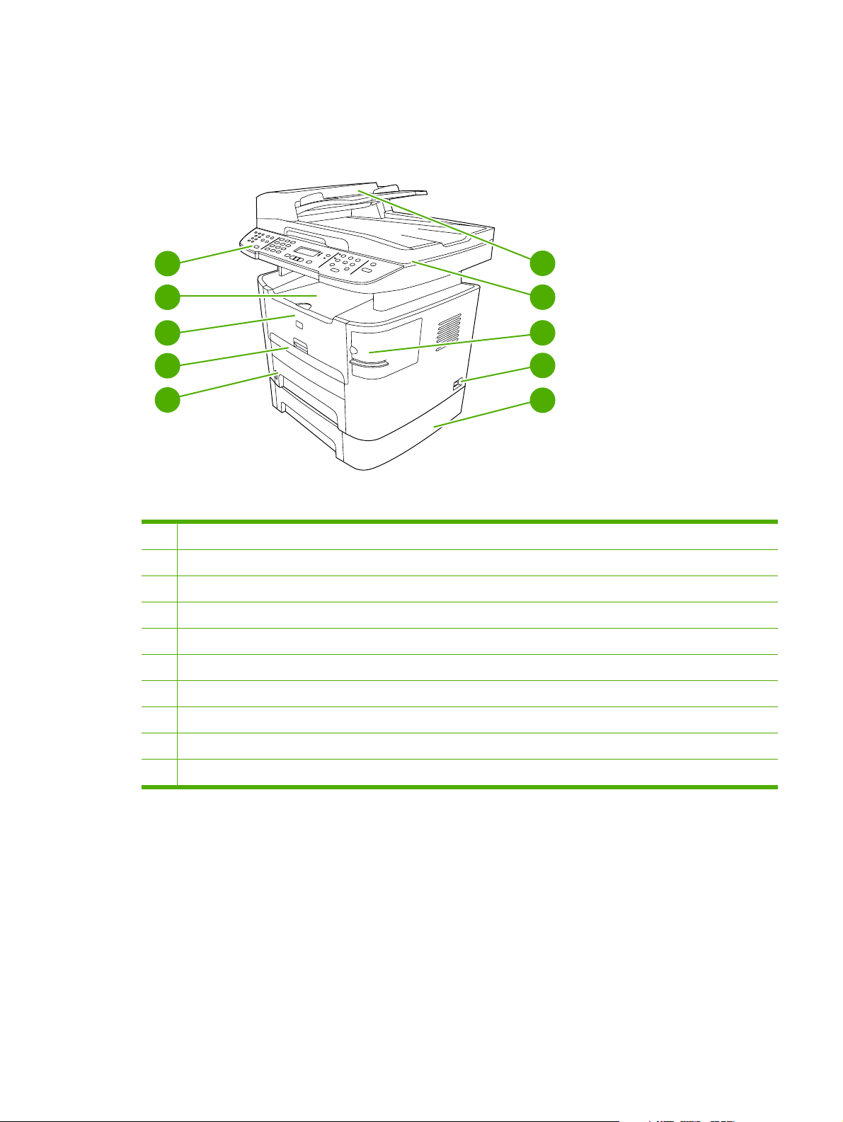
Product walkaround
HP LaserJet 3390/3392 all-in-one
5
4
3
2
1
Figure 1-2 Front view
1 Tray 2
2 Priority input slot (tray 1)
3 Print-cartridge door
4 Top (face-down) output bin
5 Control panel
6 Automatic document feeder (ADF)
6
7
8
9
10
7 Flatbed scanner glass (under the scanner cover)
8 Convenience stapler (HP LaserJet 3392 all-in-one only)
9 Power switch
10 Optional tray 3 (standard on the HP LaserJet 3392 all-in-one)
ENWW Product walkaround 7
Page 30
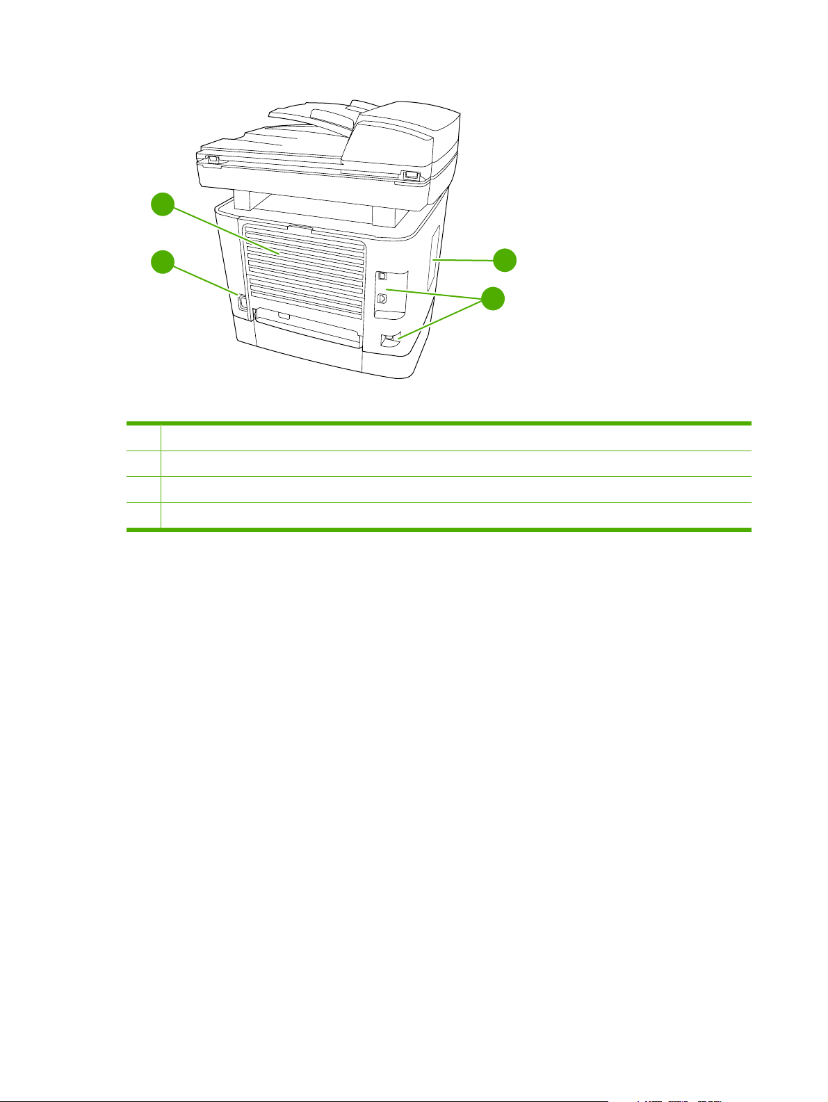
12
11
14
Figure 1-3 Back view
11 Power connector
12 Rear (face-up) output bin door (used for straight-through output path)
13 DIMM door
14 Interface ports
13
8 Chapter 1 Product information ENWW
Page 31

Interface ports
1
2
3
Figure 1-4 Interface ports
1
Hi-Speed USB 2.0 port
2
Network port
3
Fax port
Control panel
1
Shift
05
06
07
08
2
Figure 1-5 Control panel
1
Fax controls. Use the fax controls to change commonly used fax settings.
3
4
5
2
Alphanumeric buttons. Use the alphanumeric buttons to type data into the all-in-one control-panel display and dial
telephone numbers for faxing.
3
Menu and cancel controls. Use these controls to select menu options, determine the all-in-one status, and cancel the
current print job.
4
Copy controls. Use these controls to change commonly used default settings and to start copying.
5
Scan controls. Use these controls to scan to e-mail or to a folder.
ENWW Product walkaround 9
Page 32

Model and serial numbers
U
L
An identification label is located on the inside of the print-cartridge door of the all-in-one. This label
contains the model and serial numbers. The serial number shows information about the country/region
of origin, revision level, production code, and production number of the all-in-one. The label also contains
power-rating and regulatory information.
HEWLETT-PACKARD
11311 CHINDEN BLVD.
BOISE, IDAHO 83714
USA
Numero du produit
Product No.Q6502A
CNBR212347
CNBR212347
Numero de Serie
Serial No.
CNBR212347
CNBR212347
Product of China
Produit de Chine
é
CNMX123456
Numero reglementaire du modele
Regulatory Model Number:
BOISB-0402-03
110- 127V ~AC
50/60 Hz, 4.5A (4,5A)
Manufactured:
Fabrique le
September 23, 2005
o
N de certificacion del modem
TTDHPBO05-606
I.T.E.
53ZQ
U
CUS
L
LISTED
TestedTo Comply
With FCC Standards
FOR HOME OR OFFICE USE
US: 6DNFZ07BQ6500A
Ringer Equivalence (REN):0.7B
This product conforms with
CDRH radiation performance
standard 21 CFR chapter 1,
sub-chapter J.
Figure 1-6 HP LaserJet 3390/3392 all-in-one identification label
NYCE
>PET<SITE:MX2
10 Chapter 1 Product information ENWW
Page 33

Software description
Supported drivers
The following printer drivers are provided. If the printer driver you want is not on the all-in-one CD or is
not available on
and request a driver for the all-in-one.
NOTE The most recent drivers are available at www.hp.com. depending on the configuration
of Windows-based computers, the installation program for the all-in-one software automatically
checks the computer for Internet access to obtain the latest drivers.
Table 1-4 Supported printer drivers
www.hp.com, contact the manufacturer or distributor of the program that you are using,
Operating
1
system
Microsoft
Windows® 98
Microsoft
Millennium Edition
(Me)
Windows 2000
Windows XP
Windows Server
2003
Mac OS X V10.3
and Mac OS X
V10.4
1
2
®
Not all all-in-one features are available from all drivers or operating systems. See the context-sensitive help in the printer driver
for available features.
A Macintosh printer driver and the necessary PostScript® (PS) Printer Description Files (PPDs) are included with the all-inone.
Fax driver PCL 6 printer
driver
X
X
X
X
X X X
X
X
X
PCL 5 printer
driver
X
X
X
X
X
PS printer driver PPD2 printer
X
X
X
X
X
driver
Additional drivers
The following drivers are not included on the CD, but are available from the Internet.
®
Model Scripts
UNIX
●
Linux drivers
●
Windows XP 64-bit drivers
●
You can obtain Model Scripts for UNIX and Linux by downloading them from the Internet. For Linux
support see
www.hp.com/linux. For UNIX support see www.hp.com/gp/jetdirectunix_software.
ENWW Software description 11
Page 34

Software installation
If your computer meets the recommended minimum requirements, you have two options when installing
the software from the CDs that came with the all-in-one.
Typical installation
The following software is included with a typical installation:
HP ToolboxFX
●
HP LaserJet Scan program and driver
●
HP LaserJet Fax
●
Readiris OCR (not installed with other software; separate installation is required)
●
Printer drivers (PCL 6, PCL 5e, PostScript Level 2 emulation)
●
HP Director (Macintosh)
●
HP All-in-One Setup Assistant (Macintosh)
●
Minimum installation
The following software is included with a typical installation:
PCL 6 printer driver
●
HP LaserJet Scan program and driver
●
NOTE Minimum installation supports faxing by using the control panel.
12 Chapter 1 Product information ENWW
Page 35

Software for Windows
When you install the software for Windows, you can directly connect the all-in-one to a computer by
using a USB cable, or you can connect the all-in-one to a network by using the internal print server. See
the getting started guide for installation instructions, and see the Readme file for the latest software
information.
Software components for Windows
HP ToolboxFX
Perform a typical installation in order to use HP ToolboxFX.
HP ToolboxFX provides links to all-in-one status information and help information, such as the user
guide, and tools for troubleshooting all-in-one problems. See
on page 68.
Embedded Web server (EWS)
The EWS is a Web-based interface that provides simple access to all-in-one status and configurations,
including network configurations and Smart Printing Supplies (SPS) functionality.
You can gain access to the EWS through the network connection to the all-in-one. Type the all-in-one
IP address in a Web browser to open the all-in-one EWS home page in the browser. From the home
page, you can use the tabs and left navigation menu to check the status of the all-in-one, configure the
all-in-one, or check the status of the supplies.
Using the HP ToolboxFX
The following are supported browsers:
Internet Explorer 5.0 or later
●
Netscape Navigator 4.75 or later
●
Opera 6.05 or later
●
Safari 1.2 or later
●
ENWW Software for Windows 13
Page 36

Software for Macintosh
For Mac OS X V10.3 and Mac OS X V10.4, use Print Center to print.
NOTE For Macintosh computers, HP ToolboxFX is not supported.
HP Director
HP Director is a software program for working with documents. When the document is loaded into the
ADF and the computer is connected directly to the all-in-one, HP Director appears on the computer
screen to initiate faxing, scanning, or changing settings on the all-in-one through Macintosh Configure
Device.
Also included is the HP all-in-one Setup Assistant, which sets up the fax and print queues.
Macintosh Configure Device (Mac OS X V10.3 and Mac OS X V10.4)
Macintosh Configure Device is a Web-based program that provides access to information about the allin-one (or example, information about supplies status and all-in-one settings). Use Macintosh Configure
Device to monitor and manage the all-in-one from the computer.
NOTE You must perform a complete software installation to use Macintosh Configure Device.
Check the all-in-one status and print information pages.
●
Check and change all-in-one settings.
●
Check default print settings.
●
Check and change fax settings, including IP configuration, Advanced, mDNS, SNMP, network
●
configuration, and fax reports.
You can view Macintosh Configure Device when the all-in-one is directly connected to a computer or
when it is connected to the network.
NOTE You do not have to have Internet access to open and use Macintosh Configure Device.
To view Macintosh Configure Device when the all-in-one is connected to the computer
1. Open HP Director by clicking the HP Director icon in the dock.
2. In HP Director, click Settings.
3. Select Configure Device to open the Macintosh Configure Device home page in a browser.
To view Macintosh Configure Device when the all-in-one is connected to the network
1. Open one of the following browsers:
Internet Explorer 5.0 or later
●
Netscape Navigator 4.75 or later
●
14 Chapter 1 Product information ENWW
Page 37

Opera 6.05 or later
●
Safari 1.2 or later
●
2. Type the IP address of the all-in-one into the Web browser to open the Macintosh Configure Device
home page.
PDEs (Mac OS X V10.3 and Mac OS X V10.4)
PDEs are code plug-ins that provide access to all-in-one features, such as information about the number
of copies, two-sided printing, and quality settings. An installation program for the PDEs and other
software is provided on the HP LaserJet 3390/3392 all-in-one CD for Macintosh.
ENWW Software for Macintosh 15
Page 38

Uninstalling software
Windows
Use the Add or Remove Programs method in Windows to remove the all-in-one software. This method
does not require you to have the software CD.
1. Click Start, point to Settings, and then click Control Panel.
NOTE In Windows XP, click Start, and then click Control panel.
2. Double-click Add or Remove Programs.
3. Scroll through the list of software programs and click HP LaserJet 3390/3392 all-in-one.
4. Click Remove.
Macintosh
To remove the software, drag the PPD files to the trash can.
16 Chapter 1 Product information ENWW
Page 39

Media specifications
Supported media weights and sizes
NOTE See the user guide for information about using media correctly.
For optimum results, use conventional 80 to 90 g/m2 (20 to 24 lb) photocopy paper. Verify that the paper
is of good quality and is free of cuts, nicks, tears, spots, loose particles, dust, wrinkles, curls, and bent
edges.
NOTE The all-in-one supports a wide range of standard and custom size print media. The
capacity of trays and bins can vary depending on media weight and thickness and on
environmental conditions. use only transparencies that are designed for use with HP LaserJet
printers. Inkjet and monochrome transparencies are not supported for this all-in-one.
Table 1-5 Single-sheet priority input slot (tray 1)
Media Dimensions
Paper Minimum 76 x 127 mm (3 x 5
inches)
Maximum 218 x 356 mm (8.5
x 14 inches)
HP cover paper
Transparencies and opaque
film
3
Labels
Envelopes
1
The all-in-one supports a wide range of standard and custom sizes of media. Check the printer driver for supported sizes.
2
Hewlett-Packard does not guarantee results when printing with other types of heavy paper.
3
Smoothness: 100 to 250 (Sheffield).
2
Same as the preceding listed
minimum and maximum
sizes.
1
Weight Capacity
60 to 163 gm2 (16 to 43 lb)
203 g/m2 (75 lb cover)
Thickness: 0.10 to 0.13 mm
(3.9 to 5.1 mils)
Thickness: up to 0.23 mm
(9 mils)
Up to 90 gm2 (16 to 24 lb)
1 sheet
1 sheet
1 sheet
1 sheet
1 sheet
Table 1-6 Tray 2 and optional tray 3
Media Dimensions
Minimum-size 148 x 147.3 mm (4.1 x
5.8 inches)
1
Weight Capacity
60 to 105 gm2 (16 to 28 lb) 250 sheets of 80 gm2 or 20 lb
paper
2
Maximum-size 216 x 356 mm (8.5 x
14 inches)
Letter 216 x 279 mm (8.5 x
A4 210 x 297 mm (8.3 x
11 inches)
11.7 inches)
ENWW Media specifications 17
Page 40

Table 1-6 Tray 2 and optional tray 3 (continued)
Media Dimensions
Legal 216 x 356 mm (8.5 x
14 inches)
16K (195 x 270 mm) 195 x 270 mm (7.7 x
10.6 inches)
16K (7.75 x 10.75 inches) 197 x 273 mm (7.8 x
10.7 inches)
16K 184 x 260 mm 184 x 260 mm (7.2 x
10.2 inches)
A5 148 x 210 mm (5.8 x
8.3 inches)
B5 (ISO 176 x 250 mm (6.9 x
9.9 inches)
B5 (JIS) 182 x 257 mm (7.2 x
10 inches)
Executive 191 x 267 mm (7.3 x
10.5 inches)
1
The all-in-one supports a wide range of standard and custom sizes of media. Check the printer driver for supported sizes.
2
Capacity can vary depending on media weight and thickness, and environmental conditions.
1
Weight Capacity
2
Table 1-7 ADF
Media Dimensions
Minimum-size 127 x 127 mm (5 x 5 inches)
Maximum-size 216 x 381 mm (8.5 x
15 inches)
1
Weight Capacity
60 to 90 gm2 (16 to 24 lb)
50 sheets
2
NOTE When faxing, copying, or scanning using the all-in-one, use the flatbed scanner if the
original is fragile, thin, thick, too small for the ADF, or a photograph. Also use the flatbed scanner
for the fit-to-page copying feature. The flatbed scanner provides the best fax, copy, and scan
resolution.
Media to avoid
The all-in-one can handle many types of media. Using media that is outside the specifications degrades
print quality and increases the chance of jams occurring.
Do not use media that is too rough.
●
Do not use media that contains cutouts or perforations other than standard 3-hole punched paper.
●
Do not use multipart forms.
●
Do not use paper that contains a watermark if you are printing solid patterns.
●
18 Chapter 1 Product information ENWW
Page 41

Media that can damage the all-in-one
In rare circumstances media can damage the all-in-one. Avoid the following types of media to prevent
possible damage:
Do not use media with staples attached.
●
Do not use transparencies designed for inkjet printers or other low-temperature printers. Use only
●
transparencies that are specified for use with HP LaserJet printers.
Do not use photo paper intended for inkjet printers.
●
Do not use paper that is embossed or coated and is not designed for the temperature of the image-
●
fuser. Select media that can tolerate temperatures of 200°C (392°F) for 0.1 second.
HP manufactures a media that is designed for the all-in-one.
Do not use letterhead paper that was produced with low-temperature dyes or thermography.
●
Preprinted forms or letterhead must use inks that can tolerate temperatures of 200°C (392°F) for
0.1 second.
Do not use any media that produces emissions, or that melts, offsets, or discolors when exposed
●
to 200°C (392°F) for 0.1 second.
To order HP LaserJet printing supplies, go to
ghp/buyonline.html/ worldwide.
www.hp.com/go/ljsupplies in the U.S. or to www.hp.com/
ENWW Media specifications 19
Page 42

20 Chapter 1 Product information ENWW
Page 43

2 Installation
Operating environment
●
Unpacking
●
Installing input devices
●
Installing the control-panel faceplate
●
Loading media
●
Installing accessories
●
ENWW 21
Page 44

Operating environment
)
Place the all-in-one on a sturdy, level surface in a well-ventilated area. Make sure that the air vents are
not blocked and that the all-in-one is installed away from direct sunlight, open flames, and ammonia
fumes.
Store or install the all-in-one in an area that meets the following requirements:
Temperature (printer; operating) 15
●
Temperature (printer; storage) -20
●
Humidity (printer; operating) 10 to 80% relative humidity (no condensation)
●
Humidity (printer; storage) 10% to 90% relative humidity (no condensation)
●
Temperature (toner cartridge; storage) -20
●
Humidity (toner cartridge; storage) 10% to 90% relative humidity (no condensation)
●
o
to 32.5oC (59o to 90.5oF)
o
to 60oC (-4o to 140oF)
o
to 40o C (-4 to 104o F)
700 mm (27.5 inches)
595 mm (23.5 inches
Figure 2-1 Operating environment
790 mm (31.0 inches)
22 Chapter 2 Installation ENWW
Page 45

Minimum system requirements
Windows® 2000
●
Windows XP
●
Windows Millennium Edition (Me)
●
Windows Server 2000
●
Windows 98
●
Mac OS X V10.3 and later
●
128 MB RAM for Windows operating systems
●
32 MB RAM for Macintosh operating systems
●
250 MB hard-disk space (full installation)
●
CD-ROM drive
●
USB port
●
ENWW Operating environment 23
Page 46

Unpacking
The following components are included in the box.
NOTE The USB and network cables are not included.
1
3
4
5
6
7
8
2
Figure 2-2 HP LaserJet 3390/3392 all-in-one package contents
Item Description
1 Automatic document feeder (ADF) input tray
2 HP LaserJet 3390/3392 all-in-one
3 Power cord
4 Fax cord
5 Print cartridge
6 Start guide and support flyer
7 CD-ROMs (software and online user guide)
9
8 250-sheet media input tray (HP LaserJet 3392 all-in-one only)
9 Control-panel faceplate (if not already installed)
Installing the supplies (for example, the print cartridge) is similar to replacing them. See Managing
supplies on page 36 for more information about installing supplies.
24 Chapter 2 Installation ENWW
Page 47

Installing input devices
ADF input tray
1. Open the ADF cover.
2. Align the two tabs on the input tray with the grooves in the ADF.
3. Slide the tray into the grooves until the tray snaps into place.
4. Close the ADF cover.
Figure 2-3 Install the ADF input tray
ENWW Installing input devices 25
Page 48

250-sheet input tray (tray 3)
CAUTION Always install the 250-sheet tray (tray 3) in the location where the all-in-one will
remain. The assembled combination is heavy, and cannot be easily moved.
1. Place the 250-sheet feeder (tray 3) on a sturdy, level surface.
2. Use the alignment pins at the corners of the tray as a guide, and place the all-in-one on top of the
tray.
3. Make sure that the right-rear connector (callout 1) connects with the all-in-one.
1
Figure 2-4 Install the 250-sheet input tray
26 Chapter 2 Installation ENWW
Page 49

Installing the control-panel faceplate
NOTE The control-panel faceplate might already be installed.
1. Lift the scanner cover.
2. Align the control-panel faceplate with the all-in-one.
3. Beginning in the center of the faceplate and working outward, press the faceplate until it snaps into
place.
3
2
1
2
3
Figure 2-5 Install the control-panel faceplate
ENWW Installing the control-panel faceplate 27
Page 50

Loading media
Loading documents to fax, copy, or scan
NOTE For the best-quality scans, use the flatbed scanner.
To load originals onto the flatbed scanner
1. Make sure that the automatic document feeder (ADF) contains no media.
2. Lift the scanner cover.
3. Place the original document face-down on the flatbed scanner glass with the upper-left corner of
the document at the lower-right corner of the glass.
Figure 2-6 Load a document onto the flatbed scanner
4. Gently close the scanner cover.
The document is ready to be faxed/copied/scanned.
28 Chapter 2 Installation ENWW
Page 51

To load originals into the ADF
NOTE The ADF capacity for the HP LaserJet 3390/3392 all-in-one is up to 50 sheets of 80 g/
2
m
or 20 lb media.
1. Insert the stack of originals into the ADF input tray top-edge-first, with the media stack face-up and
the first page to be copied on the top of the stack. Slide the stack into the ADF until it does not
move any farther.
Figure 2-7 Load documents into the ADF (1 of 2)
2. Adjust the media guides until they are snug against the stack.
Figure 2-8 Load documents into the ADF (2 of 2)
3. The document is ready to be faxed, copied, or scanned.
ENWW Loading media 29
Page 52

Loading the single-sheet priority input slot (tray 1)
NOTE The single-sheet priority input slot on the HP LaserJet 3390/3392 all-in-one holds one
sheet of media up to 163 g/m
jams and skewing, always adjust the side media guides before feeding the media.
Load the media with the top forward and the side to be printed on facing up.
2
(43 lb) in weight or one envelope, transparency, or card. To prevent
Figure 2-9 Load the single-sheet priority input slot (tray 1)
Loading tray 2 or optional tray 3
1. Pull out tray 2 or tray 3.
Figure 2-10 Loading tray 2 or tray 3 (1 of 3)
2. Adjust the media guides to the size of the media.
30 Chapter 2 Installation ENWW
Page 53

3. Place the media in the tray.
NOTE Do not fan the media before placing it in the tray.
Figure 2-11 Load tray 2 or tray 3 (2 of 3)
4. Slide tray 2 or tray 3 into the all-in-one.
Figure 2-12 Load tray 2 or tray 3 (3 of 3)
ENWW Loading media 31
Page 54

Installing accessories
Removing and replacing a DIMM
1. Open the DIMM door.
NOTE The DIMM door is not hinged. Open the DIMM door and set it next to the all-in-one.
Figure 2-13 Removing and replacing a DIMM (1 of 4)
2. Release the locks on each side of the DIMM and pull the DIMM out of the all-in-one.
Figure 2-14 Removing and replacing a DIMM (2 of 4)
32 Chapter 2 Installation ENWW
Page 55

3. Install a replacement DIMM. Make sure that the locks on each side of the DIMM are in the locked
position
Figure 2-15 Removing and replacing a DIMM (3 of 4)
4. Replace and close the DIMM door.
Figure 2-16 Removing and replacing a DIMM (4 of 4)
ENWW Installing accessories 33
Page 56

34 Chapter 2 Installation ENWW
Page 57

3 Maintenance
Managing supplies
●
Cleaning the all-in-one
●
Managing the all-in-one
●
Using the HP ToolboxFX
●
Using Macintosh Configure Device (Mac OS X V10.3 and Mac OS X V10.4)
●
Understanding the Embedded Web server
●
ENWW 35
Page 58

Managing supplies
This section describes replacing the print cartridge, staple cassette, tray 2 pickup roller, and the tray 2
and optional tray 3 separation pad. For information about replacing the ADF pickup-roller assembly, see
Replacing the ADF pickup-roller assembly on page 124.
Inspect any parts that wear when servicing the all-in-one. Replace them as needed, based on failure or
wear rather than usage.
The following table lists approximate schedules for replacing consumables.
Life expectancies of supplies and the all-in-one
Item Capacity
HP LaserJet 3390/3392 10,000 pages-per-month
Print cartridge 2,500 pages1 (standard)
Staple cassette 1,500 staples
1
The estimated print-cartridge life is based on using letter- or A4-sized media with an average of 5% toner coverage and a
medium density-setting. Print cartridge life can be extended by using draft-mode settings to conserve toner.
50,000 pages lifetime
6,000 pages
1
(high-capacity)
Ordering supplies
NOTE To locate part numbers for supplies, see Accessories and ordering information
on page 259.
Ordering supplies
To order supplies, go to one of the following Web sites.
North America:
●
Europe and Middle East:
●
Asia Pacific countries/regions: www.hp.com/go/orders/supplies-ap
●
Latin America:
●
www.hp.com/go/orders/supplies-na
www.hp.com/go/orders/supplies-emea
www.hp.com/go/orders/supplies-la
36 Chapter 3 Maintenance ENWW
Page 59

Storing print cartridges
Follow these guidelines for storing print cartridges:
Do not remove the print cartridge from its package until you are ready to use it.
●
CAUTION To prevent damage, do not expose the print cartridge to light for more than a
few minutes.
Make sure that you store print cartridges in accordance with the environmental operating and
●
storage specifications in this manual. See
Store the print cartridges in a horizontal position.
●
Store the print cartridges in a dark, dry location away from heat and magnetic sources.
●
Environmental specifications on page 328.
Replacing and recycling supplies
Visit www.hp.com/go/environment or www.hp.com/hpinf/community/environment/productinfo/saftey for
information about the following environmental topics:
Product environmental profile sheet for this and many related HP products
●
Hewlett Packard's commitment to the environment
●
Hewlett-Packard's environmental management system
●
Hewlett Packard's end-of-life product return and recycling program
●
Material safety data sheets (MSDS), which are also available at:
●
information about supplies that contain chemical substances; such as toner.
It's easy to return and recycle your empty HP LaserJet print cartridges—free of charge—with HP Planet
Partners. HP is committed to providing inventive, high-quality products and services that are
environmentally sound, from product design and manufacturing to distribution, operation, and recycling
processes. We ensure that returned HP LaserJet print cartridges are recycled properly, processing them
to recover valuable plastics and metals for new products and diverting millions of tons of waste from
landfills. Because this cartridge is being recycled and used in new materials, it will not be returned to
you. Empty HP LaserJet print cartridges are recycled responsibly when you participate in the HP Planet
Partners program. Thank you for being environmentally responsible!
In many countries/regions, this product's printing supplies (for example, the print cartridge, drum) can
be returned to HP through the HP Printing Supplies Returns and Recycling Program. An easy-to-use
and free take back program is available in more than 35 countries/regions. Multi-lingual program
information and instructions are included in every new HP LaserJet print cartridge and supplies package.
HP Printing Supplies Returns and Recycling Program Information
Since 1992, HP has offered HP LaserJet supplies return and recycling free of charge. In 2004, HP Planet
Partners for LaserJet Supplies was available in 85% of the world market where HP LaserJet supplies
are sold. Postage-paid and pre-addressed labels are included within the instruction guide in most HP
LaserJet print cartridge boxes. Labels and bulk boxes are also available through the Web site
www.hp.com/go/recycle.
www.hp.com/go/msds, contain
Use the label to return empty, original HP LaserJet print cartridges only. Please do not use this label for
non-HP cartridges, refilled or remanufactured cartridges, or warranty returns. Printing supplies or other
objects that are inadvertently sent to the HP Planet Partners program cannot be returned.
ENWW Managing supplies 37
Page 60

More than 10 million HP LaserJet print cartridges were recycled globally in 2004 through the HP Planet
Partners supplies recycling program. This record number represents 26 million pounds of print cartridge
materials diverted from landfills. Worldwide, in 2004, HP recycled an average of 59% of the print
cartridge by weight consisting primarily of plastic and metals. Plastics and metals are used to make new
products such as HP products, plastic trays and spools. The remaining materials are disposed of in an
environmentally responsible manner.
U.S. returns
For a more environmentally responsible return of used cartridges and supplies, HP encourages the use
of bulk returns. Simply bundle two or more cartridges together and use the single, pre-paid, preaddressed UPS label that is supplied in the package. For more information in the U.S., call 1–800–
340-2445 or visit the HP Web site at
www.hp.com/go/recycle.
Non-U.S. returns
Non-U.S. customers should visit the
www.hp.com/go/recycle Web site for further information regarding
availability of the HP Printing Supplies Returns and Recycling Program.
Paper
This all-in-one is capable of using recycled papers, when the paper meets the guidelines outlined in the
HP LaserJet Printer Family Print Media Guide, which you can view on the Web at
www.hp.com/support/
ljpaperguide. This product is suitable for the use of recycled paper according to EN12281:2002.
Material restrictions
This HP product contains a battery and contains mercury in the fluorescent lamp or scanner that might
require special handling at end-of-life.
Type: Lithium carbon monofluoride (solid button cell)
Weight: Approximately. 1 gram
Location: On formatter PC board (one battery per all-in-one)
User removable: No
38 Chapter 3 Maintenance ENWW
Page 61

Replacing the print cartridge
CAUTION If toner gets on your clothing, wipe it off with a dry cloth and wash the clothing in cold
water. Hot water sets toner into the fabric.
1. Turn off the all-in-one, and open the print-cartridge door.
Figure 3-1 Replacing the print cartridge (1 of 5)
2. Grasp the handle on the print cartridge and then pull the cartridge straight out to remove it. See
the recycling information inside the replacement-print-cartridge box.
Figure 3-2 Replacing the print cartridge (2 of 5)
ENWW Managing supplies 39
Page 62

3. Remove the replacement print cartridge from its packaging. Bend the plastic tab at the end of the
cartridge, and then pull the tab until all of the sealing tape is removed from the cartridge.
Figure 3-3 Replacing the print cartridge (3 of 5)
4. Insert the print cartridge into the all-in-one until it is firmly in place.
Figure 3-4 Replacing the print cartridge (4 of 5)
40 Chapter 3 Maintenance ENWW
Page 63

5. Close the print-cartridge door, and turn on the all-in-one.
Figure 3-5 Replacing the print cartridge (5 of 5)
ENWW Managing supplies 41
Page 64

Replacing the staple cassette
1. Open the convenience stapler door.
NOTE Opening the convenience-stapler door disables the convenience stapler.
Figure 3-6 Install the staple cassette (1 of 4)
2. Remove the staple cassette from the all-in-one.
Figure 3-7 Install the staple cassette (2 of 4)
42 Chapter 3 Maintenance ENWW
Page 65

3. Insert one 1,500-staple cassette into the opening inside the convenience-stapler door.
Figure 3-8 Install the staple cassette (3 of 4)
4. Close the convenience-stapler door.
Figure 3-9 Install the staple cassette (4 of 4)
ENWW Managing supplies 43
Page 66

Replacing the tray 2 pickup roller
CAUTION Failure to correctly complete this procedure might cause damage to the all-in-one.
1. Perform the following tasks before beginning this procedure:
Turn off the all-in-one and unplug the power cord from the electrical outlet.
●
Open the print-cartridge door and remove the print cartridge.
●
Remove the tray 2 cassette.
●
Lift the all-in-one off of tray 3, if that tray is installed.
●
2. Place the all-in-one on its back on the work surface, with the front facing up.
WARNING! When you move the all-in-one into this position, the scanner cover can open
suddenly and be damaged. You must support the scanner cover to keep it from opening.
Figure 3-10 Replace the tray 2 pickup roller (1 of 7)
44 Chapter 3 Maintenance ENWW
Page 67

3. Reach into the area that you exposed when you removed tray 2. Pull the white tabs outward, and
rotate the roller-retaining collars up.
Hint Push down on the green tab to release and lower the duplex assembly to expose
more of the roller.
Figure 3-11 Replace the tray 2 pickup roller (2 of 7)
4. With the tab on the collar aligned with the slot in the plastic bracket, slide the collar to the right, and
leave the collar in this position for the remainder of this procedure.
Figure 3-12 Replace the tray 2 pickup roller (3 of 7)
ENWW Managing supplies 45
Page 68

5. Remove the pickup roller.
Figure 3-13 Replace the tray 2 pickup roller (4 of 7)
6. Insert the left side of the replacement-pickup-roller shaft into the left slot (callout 1), and insert the
right side shaft (the side with the notch) into the right slot (callout 2).
Figure 3-14 Replace the tray 2 pickup roller (5 of 7)
7. Rotate the roller shaft until the notch engages with the drive shaft and clicks into place.
46 Chapter 3 Maintenance ENWW
Page 69

8. Place the left retaining collar over the end of the roller shaft, align the tab on the collar with the slot
in the plastic bracket, and then slide the collar toward the pickup roller.
Figure 3-15 Replace the tray 2 pickup roller (6 of 7)
9. With the tab on the right collar aligned with the slot on the plastic bracket, slide the collar towards
the pickup roller. Rotate the right and left retaining collars down into the locked position.
Figure 3-16 Replace the tray 2 pickup roller (7 of 7)
10. Push up on the duplex assembly until it locks into place. Place the all-in-one upright on the work
surface with the top of the all-in-one facing up.
ENWW Managing supplies 47
Page 70

WARNING! When you move the all-in-one into this position, the scanner cover can open
suddenly and be damaged. You must support the scanner cover to keep it from opening.
11. Perform the following tasks after completing this procedure.
Replace the all-in-one on tray 3, if that tray was installed.
●
Replace the tray 2 cassette.
●
Open the print-cartridge door and install the print cartridge.
●
Plug the power cord into an electrical outlet, and turn on the all-in-one.
●
48 Chapter 3 Maintenance ENWW
Page 71

Replacing the tray 2 and optional tray 3 separation pad
1. Remove tray 2 or tray 3.
Figure 3-17 Replace the tray 2 or tray 3 separation pad (1 of 6)
2. Locate the separation pad.
Figure 3-18 Replace the tray 2 or tray 3 separation pad (2 of 6)
ENWW Managing supplies 49
Page 72

3. Remove two screws.
Figure 3-19 Replace the tray 2 or tray 3 separation pad (3 of 6)
4. Remove the separation pad.
CAUTION Before you remove the separation pad, take note of how it is positioned in the
tray.
Figure 3-20 Replace the tray 2 or tray 3 separation pad (4 of 6)
50 Chapter 3 Maintenance ENWW
Page 73

5. Install the replacement separation pad.
Figure 3-21 Replace the tray 2 or tray 3 separation pad (5 of 6)
6. Replace the two screws, and return the tray to the all-in-one.
Figure 3-22 Replace the tray 2 or tray 3 separation pad (6 of 6)
ENWW Managing supplies 51
Page 74

HP policy on non-HP supplies
Hewlett-Packard Company cannot recommend the use of non-HP supplies, either new or
remanufactured. Because they are not HP products, HP cannot influence their design or control their
quality. Service or repairs required as a result of using a non-HP supply will not be covered under the
warranty.
When you insert a supply into the all-in-one, the all-in-one will inform you if the supply is not a genuine
HP supply. If you insert a genuine HP supply that has reached the low state from another HP device,
the all-in-one identifies the supply as non-HP. Simply return the supply to the original device to reactivate
the HP features and functionality.
Resetting the all-in-one for non-HP supplies
When you install a non-HP print cartridge, Unauthorized appears on the control-panel display. In order
to print with this supply, you must press
CAUTION The all-in-one will not stop printing when this type of supply is empty. Damage to the
all-in-one could occur if the all-in-one prints with an empty non-HP print cartridge. See
Packard limited warranty statement on page 330 and Print Cartridge Limited Warranty
Statement on page 331.
when you install this non-HP supply.
Hewlett-
HP fraud hotline
Call the HP fraud hotline if the all-in-one or HP ToolboxFX indicates that the print cartridge is not an
HP print cartridge and you think that it is genuine. HP will help determine if the product is genuine and
take steps to resolve the problem.
Your print cartridge might not be a genuine HP product if you notice the following issues:
You are experiencing a large number of problems with the print cartridge.
●
The print cartridge does not look like it usually does (for example, the pull tab or the box is different).
●
In the United States, call toll-free: 1-877-219-3183.
Outside the United States, you can call collect. Dial the operator and ask to place a collect call to this
telephone number: 1-770-263-4745. If you do not speak English, a representative at the HP fraud hotline
who speaks your language will assist you. Or, if someone who speaks your language is not available,
a language line interpreter will connect approximately one minute after the beginning of the call. The
language line interpreter is a service that will translate between you and the representative for the HP
fraud hotline.
52 Chapter 3 Maintenance ENWW
Page 75

Cleaning the all-in-one
To clean the exterior
Use a soft, damp, lint-free cloth to wipe dust, smudges, and stains off of the exterior of the all-in-one.
Cleaning the flatbed scanner glass
Dirty glass, from fingerprints, smudges, hair, and so on, slows down performance and affects the
accuracy of special features such as fit-to-page and copy.
NOTE If streaks or other defects appear only on copies produced from the ADF, clean the ADF
scanner glass (step 3). It is not necessary to clean the flatbed scanner glass.
1. Turn off the all-in-one, unplug the power cord from the electrical outlet, and raise the scanner cover.
2. Clean the glass by using a soft cloth or sponge that has been moistened with nonabrasive glass
cleaner.
CAUTION Do not use abrasives, acetone, benzene, ammonia, ethyl alcohol, or carbon
tetrachloride on any part of the all-in-one; these can damage the all-in-one. Do not place
liquids directly on the glass. They might seep under it and damage the all-in-one.
Figure 3-23 Cleaning the scanner glass (1 of 2)
ENWW Cleaning the all-in-one 53
Page 76

3. Clean the ADF scanner glass by using a soft cloth or sponge that has been moistened with
nonabrasive glass cleaner.
Figure 3-24 Cleaning the scanner glass (2 of 2)
54 Chapter 3 Maintenance ENWW
Page 77

Cleaning the scanner-cover backing
1. Turn off the all-in-one, unplug the power cord from the electrical outlet, and raise the scanner cover.
2. Clean the white scanner-cover backing by using a soft cloth or sponge that has been moistened
with mild soap and warm water. Also, clean the ADF scanner glass (callout 1) next to the flatbed
scanner glass.
1
Figure 3-25 Cleaning the scanner-cover backing
3. Wash the backing gently to loosen debris; do not scrub the backing.
4. Dry the backing by using a chamois or soft cloth.
CAUTION Do not use paper-based wipes because they might scratch the backing.
5. If this does not clean the backing well enough, repeat the previous steps and use isopropyl alcohol
to dampen the cloth or sponge, and then wipe the backing thoroughly with a damp cloth to remove
any residual alcohol.
ENWW Cleaning the all-in-one 55
Page 78

Cleaning the tray 2 pickup roller
1. Perform the removal steps from Replacing the tray 2 pickup roller on page 44.
2. Gently wipe the roller with a lint-free cloth moistened with water.
Figure 3-26 Cleaning the tray 2 pickup roller (1 of 6)
3. Use a dry lint-free cloth to wipe the roller and remove loosened dirt.
Figure 3-27 Cleaning the tray 2 pickup roller (2 of 6)
56 Chapter 3 Maintenance ENWW
Page 79

4. Allow the roller to dry completely before you reinstall it.
Figure 3-28 Cleaning the tray 2 pickup roller (3 of 6)
5. Insert the left side of the pickup-roller shaft into the left slot (callout 1), and insert the right-side shaft
(the side with the notch) into the right slot (callout 2).
Figure 3-29 Cleaning the tray 2 pickup roller (4 of 6)
6. Rotate the roller shaft until the notch engages with the drive shaft and clicks into place.
ENWW Cleaning the all-in-one 57
Page 80

7. Place the left retaining collar over the end of the roller shaft, align the tab on the collar with the slot
in the plastic bracket, and then slide the collar toward the pickup roller.
Figure 3-30 Cleaning the tray 2 pickup roller (5 of 6)
8. With the tab on the right collar aligned with the slot on the plastic bracket, slide the collar towards
the pickup roller. Rotate the right and left retaining collars down into the locked position.
Figure 3-31 Cleaning the tray 2 pickup roller (6 of 6)
9. Push up on the duplex assembly until it locks into place, and place the all-in-one upright on the
work surface with the top of the all-in-one facing up.
58 Chapter 3 Maintenance ENWW
Page 81

WARNING! When you move the all-in-one into this position, the scanner cover can open
suddenly and be damaged. You must support the scanner cover to keep it from opening.
10. Perform the following tasks after completing this procedure.
Replace the all-in-one on tray 3, if that tray was installed.
●
Replace the tray 2 cassette.
●
Open the print-cartridge door and install the print cartridge.
●
Plug the power cord into an electrical outlet, and turn on the all-in-one.
●
ENWW Cleaning the all-in-one 59
Page 82

Cleaning the ADF pickup-roller assembly
1. Perform the removal steps from Replacing the ADF pickup-roller assembly on page 124.
2. Wipe the assembly with a soft cloth.
Figure 3-32 Cleaning the ADF pickup-roller assembly (1 of 7)
3. Return the assembly to the same place in the ADF. The largest roller goes in back, and the gear
side is away from you.
Figure 3-33 Cleaning the ADF pickup-roller assembly (2 of 7)
60 Chapter 3 Maintenance ENWW
Page 83

4. Lower the green lever until the flat green part fits between the rollers. Press down on the green
lever until you hear a snap.
Figure 3-34 Cleaning the ADF pickup-roller assembly (3 of 7)
5. To check for correct installation, lift the green lever until it remains open. The pickup-roller assembly
should be secured to the lever and should not fall out.
Figure 3-35 Cleaning the ADF pickup-roller assembly (4 of 7)
ENWW Cleaning the all-in-one 61
Page 84

6. Make sure that both sides of the assembly are secured with the green hooks.
Figure 3-36 Cleaning the ADF pickup-roller assembly (5 of 7)
7. Lower the green lever and the roller assembly and close the ADF cover.
Figure 3-37 Cleaning the ADF pickup-roller assembly (6 of 7)
62 Chapter 3 Maintenance ENWW
Page 85

8. Plug in the all-in-one, and then turn it on.
Figure 3-38 Cleaning the ADF pickup-roller assembly (7 of 7)
Cleaning the print path
During the printing process, paper, toner, and dust particles can accumulate inside the all-in-one. Over
time, this buildup can cause print-quality problems such as toner specks or smearing. The all-in-one
has a cleaning mode that can correct and prevent these types of problems.
Figure 3-39 Cleaning the print path
Cleaning the print path by using HP ToolboxFX
Use HP ToolboxFX to clean the print path. This is the recommended cleaning method. If you do not
have access to HP ToolboxFX, use the method in
panel on page 64.
ENWW Cleaning the all-in-one 63
Cleaning the print path by using the all-in-one control
Page 86

NOTE Not all operating systems support the HP ToolboxFX utility program.
1. Make sure that the all-in-one is turned on and in the Ready state.
2. Open the HP ToolboxFX.
3. On the Troubleshooting tab, click Maintenance, click Cleaning Page, and then click Print. A
page with a pattern prints from the all-in-one.
4. At the all-in-one, remove any print media that might be in tray 1 (the priority input slot).
5. Remove the page that printed and load it face-down into tray 1.
6. At the computer, click Clean.
Cleaning the print path by using the all-in-one control panel
1. Press Menu.
2. Use the < or the > button to find the Service menu.
3. Press
4. Press
5. Load plain letter or A4 paper and begin the cleaning process. The page feeds through the all-in-
one slowly. Discard the page when the process is completed.
, and then use the < or the > button to find Cleaning Mode.
.
64 Chapter 3 Maintenance ENWW
Page 87

Managing the all-in-one
Information pages
Information pages reside within the all-in-one memory. These pages help to diagnose and solve
problems with the all-in-one.
NOTE If the all-in-one language was not correctly set during installation, you can set the
language manually so the information pages print in one of the supported languages. Change
the language by using HP ToolboxFX.
To print the demo page
1. Press Menu.
2. Use the < or > button to find Reports, and then press
3. Use the < or > button to find Demo page, and then press
NOTE You can also print the demo page by using the HP ToolboxFX.
To print the usage page
1. Press Menu.
2. Use the < or > button to find Reports, and then press
3. Use the < or > button to find Usage page, and then press
To print the configuration page
An example of a configuration page follows this procedure.
1. Press Menu.
2. Use the < or > button to find Reports, and then press
.
.
.
.
.
ENWW Managing the all-in-one 65
Page 88

3. Use the < or > button to find Config report, and then press .
hp LaserJet
configuration page
3390/3392
1
7
1 Product Information. This section contains basic information about the all-in-one, such as the all-in-one name
and serial number.
2 Memory. This section lists memory-related information such as the total memory that is installed.
3 Paper Settings. This section lists information about the media type for each tray and about the type settings for
all of the media that the all-in-one supports
4 Copy Settings. This section lists the all-in-one default copy settings.
5 Product Settings. This section lists information that is gathered during software installation, including the
language and country/region name.
6 Installed personalities and Options. This section contains information about optional items that might be
installed, such as a DIMM.
7 Print Settings. This section contains information about all-in-one settings that are configured in the printer driver
or the HP ToolboxFX.
A second page also prints. On this page, the Fax Settings section provides details about the all-in-one fax settings.
To print the supplies status page
1. Press Menu.
2. Use the < or > button to find Reports, and then press
.
66 Chapter 3 Maintenance ENWW
Page 89

3. Use the < or > button to find Supplies Status, and then press .
NOTE You can also print the supplies status page by using the HP ToolboxFX.
hp LaserJet 3390
1
2
3
1 Print-cartridge area. This section contains information about HP print cartridges. This information includes the
print-cartridge part number, whether the cartridge toner level is low, and the remaining life for the cartridge (shown
as a graphic, and as the estimated number of pages remaining). This information might not be provided for nonHP supplies. In some cases, if a non-HP supply is installed, an alert message appears instead.
2 Ordering Information. This section contains basic information about how to order new HP supplies. See Ordering
supplies on page 36
3 Recycling Information. This section lists the all-in-one default copy settings. See Replacing and recycling
supplies on page 37
To print the network configuration page
1. Press Menu.
2. Use the < or > button to find Reports, and then press
3. Use the < or > button to find Network config., and then press
.
.
ENWW Managing the all-in-one 67
Page 90

Using the HP ToolboxFX
The HP ToolboxFX is a Web-based program that you can use to complete the following tasks:
Check the all-in-one status.
●
Configure the all-in-one settings.
●
View troubleshooting information.
●
View online documentation.
●
You can view the HP ToolboxFX when the all-in-one is directly connected to your computer or when it
is connected to the network. You must perform a typical software installation to use HP ToolboxFX.
NOTE The HP ToolboxFX is not supported for Windows 98 SE or Macintosh operating systems.
To use the HP ToolboxFX, the TCP/IP protocol must be installed on the computer.
NOTE You do not have to have Internet access to open and use the HP ToolboxFX.
To view the HP ToolboxFX
Open the HP ToolboxFX in one of these ways:
In the Windows system tray or on the desktop, double-click the HP ToolboxFX icon.
●
On the Windows Start menu, click Programs (or All Programs in Windows XP), click HP, click
●
HP LaserJet 3390/3392 all-in-one, and then click HP ToolboxFX.
The HP ToolboxFX software contains the following tabs, and the information about each tab is on the
specified page:
Status on page 68
●
Alerts on page 69
●
Fax on page 70
●
Help (Documentation) on page 73
●
System settings on page 74
●
Print settings on page 76
●
Network settings on page 77
●
Status
The HP ToolboxFX Status tab contains links to the following main pages:
Device Status. View all-in-one status information. This page indicates all-in-one conditions such
●
as a jam or an empty tray. After you correct a problem with the all-in-one, click Refresh Status to
update the all-in-one status.
Supplies Status. View detailed supplies status such as the estimated percentage of toner
●
remaining in the print cartridge and the number of pages that have been printed with the current
print cartridge. This page also has links to order supplies and to find recycling information.
68 Chapter 3 Maintenance ENWW
Page 91

Device configuration. View a detailed description of the current all-in-one configuration, including
●
the amount of memory that is installed and whether optional trays are installed.
Network configuration. View a detailed description of the current network configuration, including
●
the IP address and network status.
Print Info Pages. Print the Configuration page and various other information pages that are
●
available for the all-in-one, such as the Supplies Status page and the Demo page.
Event Log. View a history of all-in-one errors. The most recent error is at the top of the list.
●
Event log
The Event log is a four-column table where the all-in-one events are logged for your reference. The log
contains codes that correspond to the error messages that appears on the all-in-one control-panel
display. The number in the Page Count column specifies the total number of pages that the all-in-one
had printed when the error occurred. The Event log also contains a brief description of the error. For
more information about error messages, see
Control-panel messages on page 207.
Alerts
The HP ToolboxFX Alerts tab contains links to the following main pages:
Set up Status Alerts. Set up the all-in-one to send pop-up alerts for certain events, such as low
●
toner levels.
Set up E-mail Alerts. Set up the all-in-one to send e-mail alert messages for certain events, such
●
as low toner levels.
Set up status alerts
Use HP ToolboxFX to set up the all-in-one so that it issues pop-up alerts when certain events occur.
Events that trigger alerts include jams, low levels of toner in HP print cartridges, non-HP print cartridge
in use, empty input trays, and specific error messages.
Select the pop-up format, the tray icon format, or both for the alerts. The pop-up alerts only appear when
the all-in-one is printing from the computer on which you set up the alerts.
NOTE You must click Apply before changes take effect.
Set up e-mail alerts
Use HP ToolboxFX to configure up to two e-mail addresses to receive alerts when certain events occur.
You can specify different events for each e-mail address. Specify the information for the e-mail server
that will send out the e-mail alert messages for the all-in-one.
NOTE You must click Apply before changes take effect.
ENWW Using the HP ToolboxFX 69
Page 92

Fax
Use the HP ToolboxFX Fax tab to perform fax tasks from the computer. The Fax tab contains links to
the following main pages:
Fax Tasks. Perform such tasks as sending a fax or clearing the fax memory, or set the fax receive
●
mode.
Fax Phone Book. Add, edit, or delete entries in the all-in-one phone book.
●
Fax Send Log. View all of the recent faxes that have been sent from the all-in-one.
●
Fax Receive log. View all of the recent faxes that have been received by the all-in-one.
●
Fax Dat Properties. Manage the space used to store faxes on a computer. These settings apply
●
only if you have chosen to send or receive faxes remotely from the computer.
Fax tasks
The following three options are available when receiving a fax:
Print the fax. You can also select an option to have a message appear on a computer to notify
●
about when the fax was printed.
Receive the fax on your computer. You can also select an option to have a message appear on
●
a computer to notify about when the fax arrives. If the fax machine is connected to multiple
computers, only one computer can be designated to receive faxes.
Forward the fax to another fax machine.
●
For more information about fax tasks, see
NOTE You must click Apply before changes take effect.
Fax on page 70.
Fax phone book
Use the HP ToolboxFX Fax phone book to add and remove individuals or groups on a speed-dial list,
import phone books from a variety of sources, and update and maintain a contact list.
To add an individual contact to a speed-dial list:
●
1. Select the check box next to the speed dial number that you want to specify.
2. Type the contact name in the Contact Name window.
3. Type the fax number in the Fax number window.
4. Click Add/Edit.
To add a group of contacts to a speed-dial list:
●
1. Select the check box next to the speed-dial number that you want to specify.
2. Click New/Edit Group.
70 Chapter 3 Maintenance ENWW
Page 93

3. Double-click a contact name from the list on the left to move it to the group list on the right, or
select a name on the left and then click the appropriate arrow to move it to the group list on
the right. You can also use those two methods to move names from right to left.
4. When you have created a group, type a name in the Group name window, and then click
OK.
To edit an existing individual speed-dial entry:
●
1. Click anywhere on the row that contains the contact name to select it.
2. Type changes in the appropriate windows, and then click Add/Edit.
You can also make changes directly in the phone book directory list by clicking the entry and
typing your changes. Make sure that you do not have a check mark in the Select column.
To edit an existing group-speed-dial entry:
●
1. Click anywhere on the row containing the group name to select it, and then click New/Edit
Group.
2. Make any required changes, and then click OK.
You can make changes to the name of the group directly in the phone book directory list by
clicking the entry and typing your changes. Make sure that you do not have a check mark in
the Select column.
To delete an entry from the speed-dial list: Select the item and then click Delete.
●
To move speed-dial entries:
●
1. Select the entry and then click Move, or you can select Move and then specify the entry in
the dialog box.
2. Select Next empty row, or specify the number of the row where you want to move the entry.
NOTE If you specify a row that is occupied, the new entry will overwrite the existing entry.
To import contacts from a phone book that exists in Lotus Notes, Outlook, or Outlook Express:
●
1. Click Import Phone Book.
2. Select the appropriate software program, navigate to the appropriate file, and then click OK.
You can also select individual entries from the phone book instead of importing the entire
phone book.
To select all of the entries in your speed-dial list: Click the Select column heading.
●
In addition to numerical digits, the following are valid characters for fax numbers:
(
●
)
●
+
●
-
●
ENWW Using the HP ToolboxFX 71
Page 94

*
●
#
●
R
●
W
●
.
●
,
●
<space>
●
NOTE You must click Apply before changes take effect.
72 Chapter 3 Maintenance ENWW
Page 95

Fax send log
The HP ToolboxFX Fax send log lists all recently sent faxes and information about them, including the
date and time sent, job number, fax number, page count, and the results.
When you send a fax from a computer that is connected to the all-in-one, the fax contains a View link.
Click this link to open a new page that provides information about the fax.
Click any column heading in the Fax send log to re-sort the information in that column in ascending or
descending order.
The Results column shows the status of the fax. If the fax attempt was unsuccessful, this column
provides a description of why the fax was not sent.
NOTE You must click Apply before changes take effect.
For more information about faxes, see Fax on page 70.
Fax receive log
The HP ToolboxFX Fax receive log provides a list of all recently received faxes and information about
them including the date and time received, job number, fax number, page count, results, and an
abbreviated fax image.
When you receive a fax on a computer that is connected to the all-in-one, the fax contains a View link.
Clicking this link opens a new page that provides information about the fax.
Click on any column heading in the Fax receive log to re-sort the information in that column in ascending
or descending order.
The Results column provides the status of the fax. If the fax attempt was unsuccessful, this column
provides a description of why the fax was not received.
NOTE You must click Apply before changes take effect.
Help (Documentation)
The HP ToolboxFX Documentation tab contains links to the following main pages:
Troubleshooting
●
How do I? View the How Do I? Help for help with specific tasks.
●
Animated Demonstrations
●
User Guide. View information about the all-in-one usage, warranty, specifications, and support.
●
The user guide is available in both HTML and PDF format.
Install Notes. View important information about the all-in-one that is not available in the user guide.
●
The late-breaking Install Notes contain last-minute information about the all-in-one (in English only).
ENWW Using the HP ToolboxFX 73
Page 96

System settings
The HP ToolboxFX System Settings tab contains links to the following main pages:
Device information. View information about the all-in-one, such as the all-in-one description and
●
a contact person.
Paper handling. Change the all-in-one paper-handling settings, such as default paper size and
●
default paper type.
Print quality. Change the all-in-one print-quality settings.
●
Paper types. Change the all-in-one mode settings for a each media type, such as letterhead,
●
prepunched, or glossy paper.
System setup. Change the all-in-one system settings, such as all-in-one language and jam
●
recovery.
Service. Gain access to various procedures that help you maintain the all-in-one.
●
Device polling. Change the all-in-one polling settings, which determine how often
●
HP ToolboxFX collects data from the all-in-one.
Save/restore settings. Save the current settings for the all-in-one to a file on your computer. Use
●
this file to load the same settings onto another all-in-one or to restore these settings to this all-inone at a later time.
Device information
The HP ToolboxFX Device information page stores data about your all-in-one for future reference. The
information that you type in these fields appears on the Configuration page. You can type any character
in each of these fields.
NOTE You must click Apply before changes take effect.
74 Chapter 3 Maintenance ENWW
Page 97

Paper handling
Use the HP ToolboxFX paper-handling options to configure your default settings. These are the same
options that are available on the Paper Handling and Printing menus on the control panel.
You must set the asset number. The asset number is not set at the factory. This number is stored in the
all-in-one for identification purposes.
Three options are available for handling print jobs when the all-in-one is out of media:
Select Wait for paper to be loaded.
●
Select Cancel from the Paper out action drop-down list to cancel the print job.
●
Select Override from the Paper out time drop-down list to send the print job to another paper tray.
●
The Paper out time field specifies how long the all-in-one waits before acting on your selections. You
can specify from 0 to 3600 seconds.
NOTE You must click Apply before changes take effect.
Print quality
Use the HP ToolboxFX print-quality options to improve the appearance of your print jobs. These are the
same options that are available on the Print Quality menu on the control panel.
The four options provided for controlling print quality are resolution, REt (Resolution Enhancement
technology), print density, and Economode.
Resolution. Select 600 resolution for average print jobs and Fast Res 1200 for higher-quality print
●
jobs. Select ProRes 1200 for the highest-quality print job, but a longer printing time.
REt. You can turn on REt, which HP provides for improved print quality.
●
Print density. For increased print density, select a higher number. For decreased print density,
●
select a lower number.
Economode. Turn Economode on when you are printing average print jobs. Economode reduces
●
print quality, but increases the life of your print cartridge. To increase print quality, turn Economode
off. HP does not recommend full-time use of Economode.
NOTE You must click Apply before changes take effect.
Paper types
Use these HP ToolboxFX paper-types options to configure print modes that correspond to the various
media types. When you select Restore Modes, all of the modes are reset to the factory settings.
NOTE You must click Apply before changes take effect.
ENWW Using the HP ToolboxFX 75
Page 98

System setup
Use the HP ToolboxFX system-settings options to configure the settings for printing, faxing, copying,
and scanning. These are the same options that are available on the System Settings menu on the
control panel.
NOTE You must click Apply before changes take effect.
Service
During the printing process, paper, toner and dust particles can accumulate inside the all-in-one. Over
time, this buildup can cause print-quality problems such as toner specks or smearing. HP ToolboxFX
provides an easy method for cleaning the paper path. For more information, see
on page 63
Cleaning the print path
Device Polling
You can turn off HP ToolboxFX device polling to reduce network traffic, but you will also disable some
HP ToolboxFX features: pop-up alerts, fax log updates, the ability to receive faxes to this computer, and
scanning using the Scan To button.
To turn device polling on, do both of the following tasks:
Clear Turn off device polling in HP ToolboxFX.
●
Turn on one of the disabled device-polling features in HP ToolboxFX.
●
NOTE You must click Apply before changes take effect.
Print settings
The HP ToolboxFX Print Settings tab contains links to the following main pages:
Printing. Change the default all-in-one print settings, such as number of copies and paper
●
orientation.
PCL5e. View and change the PCL5e settings.
●
PostScript. View and change the PS settings.
●
Printing
Use the HP ToolboxFX printing-settings options to configure the settings for all print functions. These
are the same options that are available on the Print Settings menu on the control panel.
NOTE You must click Apply before changes take effect.
76 Chapter 3 Maintenance ENWW
Page 99

PCL 5e
Use the PCL5e options to configure the settings when you are using the PCL5e print personality. These
are the same options that are available on the PCL5e menu on the control panel.
NOTE You must click Apply before changes take effect.
PostScript
Use the PostScript option when you are using the PostScript print personality. When the Print
PostScript error option is turned on, the PostScript error page automatically prints when PostScript
errors occur.
NOTE You must click Apply before changes take effect.
Network settings
The network administrator can use the HP ToolboxFX Network Settings tab to control the networkrelated settings for the all-in-one when it is connected to an IP-based network.
ENWW Using the HP ToolboxFX 77
Page 100

Using Macintosh Configure Device (Mac OS X V10.3 and Mac OS X V10.4)
Macintosh Configure Device is a Web-based program that provides access to information about the allin-one (for example, information about supplies status and all-in-one settings). Use Macintosh Configure
Device to monitor and manage the all-in-one from the computer
NOTE You must perform a complete software installation to use Macintosh Configure Device.
Check the all-in-one status and print information pages.
●
Check and change all-in-one system settings.
●
Check default print settings.
●
Check and change fax settings, including fax send, fax receive, fax phone book and speed-dial
●
settings, and fax reports.
Check and change network settings, including IP configuration, Advanced, mDNS, SNMP, network
●
configuration, and password.
You can view Macintosh Configure Device when the all-in-one is directly connected to your computer
or when it is connected to the network.
NOTE You do not have to have Internet access to open and use Macintosh Configure Device.
To view Macintosh Configure Device when the all-in-one is directly connected to the computer
1. Open HP Director by clicking the HP Director icon in the dock.
2. In HP Director, click Settings.
3. Select Configure device to open the Macintosh Configure Device home page in a browser.
To view Macintosh Configure Device when the all-in-one is connected to a network
1. Open one of the following supported Web browsers:
Safari 1.2 or later
●
Microsoft Internet Explorer 5.0 or later
●
Netscape Navigator 4.75 or later
●
Opera 6.05 or later
●
2. Type the IP address of the all-in-one into the Web browser to open the Macintosh Configure Device
home page.
78 Chapter 3 Maintenance ENWW
 Loading...