

Page 1

HP IP Console Switch
User Guide
June 2003 (Second Edition)
Part Number 263924-002
Page 2

© 2003 Hewlett-Packard Development Company, L.P.
Microsoft
®
, Windows®, and Windows NT® are U. S. registered trademarks of Microsoft
Corporation.
Energy Star® is U.S. registered mark of the United States Environmental Protection Agency.
Hewlett-Packard Company shall not be liable for technical or editorial errors or omissions
contained herein. The information in this document is provided “as is” without warranty of
any kind and is subject to change without notice. The warranties for HP products are set forth
in the express limited warranty statements accompanying such products. Nothing herein
should be construed as constituting an additional warranty.
HP IP Console Switch User Guide
June 2003 (Second Edition)
Part Number 263924-002
Page 3

Contents
About This Guide
Audience Assumptions...................................................................................................... ix
Important Safety Information............................................................................................ ix
Symbols on Equipment ..................................................................................................... ix
Rack Stability .................................................................................................................... xi
Symbols in Text.................................................................................................................xi
Related Documents........................................................................................................... xii
Getting Help ..................................................................................................................... xii
Technical Support...................................................................................................... xii
HP Website ............................................................................................................... xiii
Authorized Reseller .................................................................................................. xiii
Reader’s Comments ........................................................................................................ xiii
Chapter 1
Overview
Features ........................................................................................................................... 1-2
Benefits............................................................................................................................ 1-3
IP Console Switch Components...................................................................................... 1-4
Chapter 2
Installing the IP Console Switch
Installation Checklist....................................................................................................... 2-2
Kit Contents .............................................................................................................. 2-2
Required Tool ........................................................................................................... 2-2
Optional Items........................................................................................................... 2-2
HP IP Console Switch User Guide iii
Page 4

Contents
Setting up Your Network.................................................................................................2-3
Rack Mounting the IP Console Switch............................................................................2-3
Using Side Mount 0U Installation............................................................................. 2-4
Using Rear Rack Installation.....................................................................................2-8
Using Standard 1U Installation ...............................................................................2-10
Configuring the IP Console Switch Hardware...............................................................2-14
Adjusting the Mouse Acceleration.................................................................................2-19
Adding Servers ..............................................................................................................2-20
Chapter 3
Expansion Module
Features............................................................................................................................ 3-1
Installing the Expansion Module Hardware ....................................................................3-3
Installing the Expansion Module into the IP Console Switch System.............................3-8
Chapter 4
Interface Adapters
Features............................................................................................................................ 4-1
Connecting an Interface Adapter to the IP Console Switch System................................4-3
Chapter 5
Cascade Console Switches
Connecting Cascade Switches to the IP Console Switch System.................................... 5-3
Cascading 2 x 8 Compaq Legacy Console Switches
into the IP Console Switch System ...........................................................................5-3
Chapter 6
Local Port Operation
Viewing and Selecting Ports and Servers ........................................................................6-1
Accessing the Main Dialog Box................................................................................6-2
Viewing the Status of your IP Console Switch System ............................................6-3
Selecting Servers.......................................................................................................6-4
Soft Switching..................................................................................................................6-5
Configuring Servers for Soft Switching....................................................................6-5
Soft Switching Servers..............................................................................................6-5
Using Basic OSD Navigation ..........................................................................................6-6
Configuring the OSD Setup Menu...................................................................................6-8
Accessing the Setup Menu........................................................................................ 6-9
iv HP IP Console Switch User Guide
Page 5

Contents
Assigning Server Names ............................................................................................... 6-10
Accessing the Names Dialog Box........................................................................... 6-10
Assigning Names to Servers................................................................................... 6-11
Assigning Device Types................................................................................................ 6-12
Accessing Devices Dialog Box............................................................................... 6-13
Assigning Device Types ......................................................................................... 6-14
Changing the Display Behavior..................................................................................... 6-15
Accessing the Menu Dialog Box ............................................................................ 6-15
Selecting the Display Order of Servers................................................................... 6-16
Setting Screen Delay Time ..................................................................................... 6-16
Controlling the Status Flag............................................................................................ 6-17
Accessing the Flag Dialog Box............................................................................... 6-18
Displaying the Status Flag ...................................................................................... 6-19
Broadcasting to Servers................................................................................................. 6-20
Accessing Broadcast Dialog Box............................................................................ 6-21
Broadcasting Selected Servers................................................................................ 6-22
Activating Broadcasting.......................................................................................... 6-22
Setting up a Scan Pattern............................................................................................... 6-22
Accessing the Scan Dialog Box.............................................................................. 6-23
Adding Servers to the Scan List.............................................................................. 6-24
Removing Servers from the Scan List .................................................................... 6-24
Starting Scan Mode................................................................................................. 6-25
Stopping Scan Mode............................................................................................... 6-25
Setting Local Console Switch Security ......................................................................... 6-25
Accessing the Security Dialog Box ........................................................................ 6-26
Changing the Password........................................................................................... 6-27
Setting Password Protection ................................................................................... 6-27
Logging on to Switch.............................................................................................. 6-28
Removing Password Protection.............................................................................. 6-28
Enabling Screen Saver Mode without Password Protection................................... 6-28
Exiting Screen Saver Mode .................................................................................... 6-29
Deactivating the Screen Saver ................................................................................ 6-29
Managing Server Tasks Using the OSD........................................................................ 6-30
Accessing the Commands Menu............................................................................. 6-31
Viewing and Disconnecting User Connections............................................................. 6-32
Viewing Current User Connections ........................................................................ 6-32
Disconnecting a User .............................................................................................. 6-33
HP IP Console Switch User Guide v
Page 6

Contents
Running System Diagnostics.........................................................................................6-35
Running Diagnostics Test .......................................................................................6-35
Resetting the PS/2 Mouse..............................................................................................6-40
Displaying Version Information ....................................................................................6-41
Chapter 7
Upgrading Firmware using TFTP
Enabling TFTP for Windows NT ....................................................................................7-1
Enabling TFTP for Windows 2000 and Windows XP.....................................................7-2
Enabling TFTP for Linux ................................................................................................7-3
Verifying TFTP for Linux......................................................................................... 7-3
Configuring TFTP for Windows......................................................................................7-4
Updating the IP Console Switch...................................................................................... 7-6
Updating the IP Console Switch Hardware............................................................... 7-6
Updating the IP Console Switch through the IP Console Viewer...........................7-12
Establishing LAN Connections......................................................................................7-16
Upgrading FLASH Firmware ........................................................................................ 7-16
Analyzing FLASH Failures.....................................................................................7-18
Upgrading Interface Adapter Firmware......................................................................... 7-19
Chapter 8
Troubleshooting
Appendix A
Regulatory Compliance Notices
Regulatory Compliance Series Number..........................................................................A-1
Federal Communications Commission Notice ............................................................... A-1
Class A Equipment................................................................................................... A-2
Class B Equipment................................................................................................... A-2
Declaration of Conformity for Products Marked
with the FCC Logo, United States Only...................................................................A-3
Modifications ...........................................................................................................A-3
Cables....................................................................................................................... A-4
Canadian Notice (Avis Canadien) .................................................................................. A-4
Class A Equipment................................................................................................... A-4
Class B Equipment................................................................................................... A-4
vi HP IP Console Switch User Guide
Page 7

Mouse Compliance Statement........................................................................................ A-4
European Union Notice.................................................................................................. A-5
Japanese Notice .............................................................................................................. A-6
BSMI Notice................................................................................................................... A-6
Appendix B
Electrostatic Discharge
Preventing Electrostatic Damage ....................................................................................B-1
Grounding Methods To Prevent Electrostatic Damage...................................................B-2
Appendix C
Power Cord Set Requirements
General Requirements .....................................................................................................C-1
Country-Specific Requirements ......................................................................................C-2
Index
Contents
HP IP Console Switch User Guide vii
Page 8

This guide provides step-by-step instructions for installation and reference
information for operation, troubleshooting, and upgrades for the
HP IP Console Switch.
Audience Assumptions
This guide is for the person who installs, administers, and troubleshoots IP Console
Switches. HP assumes you are qualified in the servicing of equipment and trained in
recognizing hazards in products with hazardous energy levels.
Important Safety Information
Before installing this product, read the Important Safety Information document
included with this product.
About This Guide
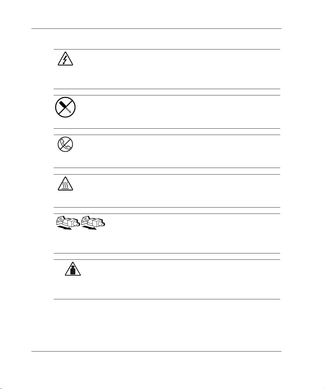
Symbols on Equipment
The following symbols may be placed on equipment to indicate the presence of
potentially hazardous conditions:
WARNING: This symbol, in conjunction with any of the following symbols,
indicates the presence of a potential hazard. The potential for injury exists if
warnings are not observed. Consult your documentation for specific details.
HP IP Console Switch User Guide ix
Page 9
About This Guide
Weight in kg
Weight in lb
This symbol indicates the presence of hazardous energy circuits or electric
shock hazards. Refer all servicing to qualified personnel.
WARNING: To reduce the risk of injury from electric shock hazards, do not
open this enclosure. Refer all maintenance, upgrades, and servicing to
qualified personnel.
This symbol indicates the presence of electric shock hazards. The area
contains no user- or field-serviceable parts. Do not open for any reason.
WARNING: To reduce the risk of injury from electric shock hazards, do not
open this enclosure.
This symbol on an RJ-45 receptacle indicates a network interface connection.
WARNING: To reduce the risk of electric shock, fire, or damage to the
equipment, do not plug telephone or telecommunications connectors into this
receptacle.
This symbol indicates the presence of a hot surface or hot component. If this
surface is touched, the potential for injury exists.
WARNING: To reduce the risk of injury from a hot component, allow the
surface to cool before touching.
These symbols, on power supplies or systems, indicate that the
equipment is supplied by multiple sources of power.
WARNING: To reduce the risk of injury from electric shock,
remove all power cords to completely disconnect power from the
system.
This symbol indicates that the component exceeds the recommended
weight for one individual to handle safely.
WARNING: To reduce the risk of personal injury or damage to the
equipment, observe local occupational health and safety requirements
and guidelines for manual material handling.
x HP IP Console Switch User Guide
Page 10
Rack Stability
WARNING: To reduce the risk of personal injury or damage to the equipment,
be sure that:
• The leveling jacks are extended to the floor.
• The full weight of the rack rests on the leveling jacks.
• The stabilizing feet are attached to the rack if it is a single-rack installation.
• The racks are coupled together in multiple-rack installations.
• Only one component is extended at a time. A rack could become unstable
if more than one component is extended for any reason.
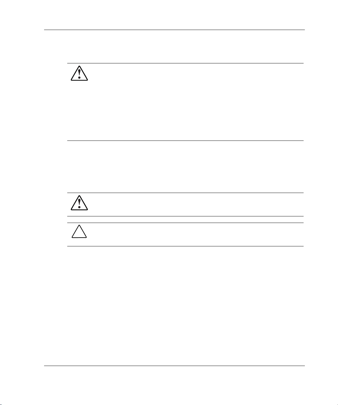
Symbols in Text
These symbols can be found in the text of this guide. They have the
following meanings.
WARNING: Text set off in this manner indicates that failure to follow directions
in the warning could result in bodily harm or loss of life.
About This Guide
CAUTION: Text set off in this manner indicates that failure to follow directions could
result in damage to equipment or loss of information.
IMPORTANT: Text set off in this manner presents essential information to explain a concept
or complete a task.
NOTE: Text set off in this manner presents additional information to emphasize or supplement
important points of the main text.
HP IP Console Switch User Guide xi
Page 11

About This Guide
Related Documents
For additional information on the topics covered in this guide, refer to the
HP IP Console Switch Software Guide.
Getting Help
If you have a problem and have exhausted the information in this guide, you can get
further information and other help in the following locations.
Technical Support
In North America, call the HP Technical Support Phone Center at 1-800-652-6672.
This service is available 24 hours a day, 7 days a week. For continuous quality
improvement, calls may be recorded or monitored. Outside North America, call the
nearest HP Technical Support Phone Center. Telephone numbers for worldwide
Technical Support Centers are listed on the HP website,
Be sure to have the following information available before you call HP:
www.hp.com.
• Technical support registration number (if applicable)
• Product serial number
• Product model name and number
• Applicable error messages
• Add-on boards or hardware
• Third-party hardware or software
• Operating system type and revision level
xii HP IP Console Switch User Guide
Page 12

HP Website
The HP website has information on this product as well as the latest drivers and flash
ROM images. You can access the HP website at
For product specific information, refer to the following website,
http://h18004.www1.hp.com/products/servers/proliantstorage/rack-options/kvm/indexconsole.html.
Authorized Reseller
For the name of your nearest authorized reseller:
• In the United States, call 1-800-345-1518.
• In Canada, call 1-800-263-5868.
• Elsewhere, see the HP website for locations and telephone numbers.
Reader’s Comments
About This Guide
www.hp.com.
HP welcomes your comments on this guide. Please send your comments and
suggestions by email to
ServerDocumentation@hp.com.
HP IP Console Switch User Guide xiii
Page 13

1
Overview
The HP IP Console Switch combines analog and digital technology to provide
flexible, centralized keyboard, video, and mouse (KVM) control of data center
servers. This solution provides enterprise customers with a significant reduction in
cable volume, secure remote access, and high performance server KVM access.
Each unit has 16 server ports (with RJ-45 connections) and provides optimal digital
video performance with a maximum resolution of 1280 x 1024 at 75 Hz, up to
15.24 meters (50 feet), and a maximum resolution of 800 x 640 at 60 Hz, up to
30.48 meters (100 feet).
The IP Console Switch works over standard LAN connections, providing access
across a 100Base-T Ethernet connection for one or up to three simultaneous IP users,
depending on the model, and for one user directly through a local port. The IP
Console Switch uses Ethernet networking infrastructure and TCP/IP protocol to
transmit KVM information between operators and connected computers.
Although 10Base-T Ethernet can be used, HP recommends a dedicated, switched
100Base-T network for improved performance.
HP IP Console Switch User Guide 1-1
Page 14

Overview
Features
The features of the IP Console Switch include:
• Both local and IP KVM functionality
• Support for up to 128 servers
• Firmware flashable over serial port and NIC
• Compatibility with HP video monitors and “hotkeys” on all HP keyboards,
including the HP TFT5600RKM
• Field-terminable CAT5 cables
• Near real-time mouse/cursor speed
• Multiple language support through programmable ROM SoftPaq—English,
Spanish, French, Dutch, German, Italian, and Japanese
• Support for 10/100 NIC ports
• Application clients that manage 25 IP Console Switches with 512 target devices
• 1U form with the ability to mount in a 0U side-mount configuration, as well as
behind HP rack-mount keyboards
1-2 HP IP Console Switch User Guide
Page 15

Benefits
The benefits of the IP Console Switch include:
• Significant reduction of KVM cable volume by using an Interface Adapter and
single unshielded twisted pair (UTP) CAT5 cabling
• Facilitation of KVM access in higher server density environments because of an
increase in the number of ports available
• KVM access through network connection
— No special software or drivers are required on the attached computers,
— Users access the unit and all attached systems through Ethernet from a user
— User can be located anywhere a valid network connection exists.
• Integration with existing HP and Compaq KVM switches, adding IP access
NOTE: The HP IP Console Switch is not compatible with HP classic analog
KVM switches.
Overview
including the host.
running the IP Console Viewer.
HP IP Console Switch User Guide 1-3
Page 16
Overview
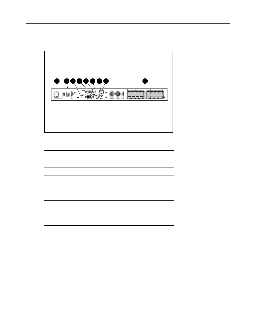
IP Console Switch Components
1 2 3 4 5 6 7 8 9
100-240V , 1.0A, 50/60 Hz
For continued protection against risk of fire, replace only with same type and rating of fuse.
T 2A, 250 VAC CAUTION:
Figure 1-1: IP Console Switch components
Item Description
1 Power connector
2 Power switch
3 Activity indicator
4 Serial download connector
5 Monitor connector for local user
6 Keyboard connector for local user
7 Mouse connector for local user
8 LAN connector
9 Server connection ports
123456789101112131415
16
1-4 HP IP Console Switch User Guide
Page 17
Overview
1
A
1
5 6 7
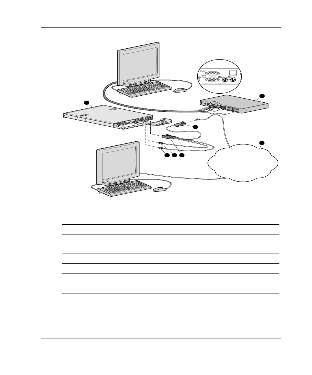
Figure 1-2: Example of an IP Console Switch
configuration
A
Item Description
1 CPU
2 IP Console Switch
3 Interface Adapter
4 Network
5 Keyboard connector
6 Mouse connector
7 Video connector
1
1
0
0
2
4
0
V
,
1
.
0
A
,
5
0
/6
0
H
z
T
2
A
,
2
5
0
V
A
C
C
A
U
T
I
O
N
:
F
o
r
con
ti
nued
p
ro
tec
tio
n
a
g
a
i
n
s
t
ris
k
o
f
f
ire
1
, r
e
p
la
ce
o
3
n
l
y
w
2
ith
s
am
5
e
t
ype
4
a
n
d
ra
7
tin
6
g
of
fu
s
e.
8
9
1
1
1
0
1
3
1
2
1
5
1
4
1
6
2
3
4
HP IP Console Switch User Guide 1-5
Page 18

2
Installing the IP Console Switch
You must install the IP Console Viewer prior to using the IP Console Switch. The
IP Console Viewer enables you to view and control a server attached to the console
switch system, configure and maintain the system, and prevent unauthorized access
to the console switch through IP connection. For more information, refer to the
HP IP Console Switch Software Guide included on the Rack Products
Documentation CD.
NOTE: The analog port does not require the IP Console Viewer software for operation. The
analog port uses the on-screen display (OSD). For more information, refer to Chapter 6.
The IP Console Switch system uses Ethernet networking infrastructures and TCP/IP
protocol to transmit keyboard, video, and mouse information between operators and
connected computers. Although 10Base-T Ethernet can be used, a dedicated,
switched 100Base-T network provides improved performance.
HP IP Console Switch User Guide 2-1
Page 19

Installing the IP Console Switch
Installation Checklist
Before installing the IP Console Switch, refer to the following lists to be sure that all
of the listed components were received.
Kit Contents
• IP Console Switch
• Power cords
• Rack mounting kit
• Download serial cable
• Documentation kit
• Firmware/software CD
• CAT5 crossover cable
Required Tool
You need a Phillips screwdriver.
Optional Items
• Expansion Module
• Interface Adapter
• UTP CAT5 cable
2-2 HP IP Console Switch User Guide
Page 20

Setting up Your Network
The IP Console Switch system uses IP addresses to uniquely identify the console
swtiches and computers running the IP Console Viewer. The IP Console Switch
supports both BootP (a subset of DHCP) and static IP addressing. HP recommends
that IP addresses be reserved for each unit and that they remain static while the
console switches are connected to the network.
Rack Mounting the IP Console Switch
The IP Console Switch ships with rack mounting brackets for easy integration in to
your rack. Before installing the console switch and other components in the rack
cabinet (if not already installed), stabilize the rack in a permanent location. Install
your equipment starting at the bottom of the rack cabinet, then work to the top. Avoid
uneven loading or overloading of rack cabinets.
NOTE: Prior to installing the IP Console Switch into the rack, connect the console switch to a
power source, using the power cords provided and power on the unit. A green activity indicator
is displayed after a few seconds. If the green activity indicator does not display, be sure that
the power is on, that the power cord is connected, and the power source is valid. For more
information, refer to the troubleshooting chapter in this guide.
Installing the IP Console Switch
Three different rack-mounting configurations are described in the sections below:
• Side mount 0U
— Type A—Square and round internal mounting rail holes
— Type B—Square internal mounting rail holes
• Rear rack mount
• Standard 1U mount
HP IP Console Switch User Guide 2-3
Page 21
Installing the IP Console Switch
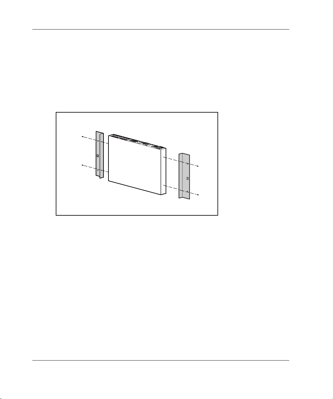
Using Side Mount 0U Installation
Type A
To side mount the IP Console Switch:
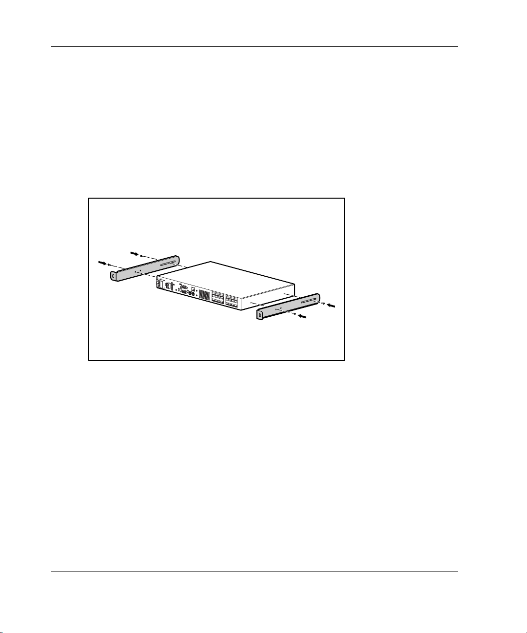
1. Attach the side-mounting brackets to the console switch, using two screws on
each side.
6
1
5
1
4
1
3
1
2
1
1
1
0
1
9
8
7
6
5
4
3
2
1
Figure 2-1: Attaching the side-mounting brackets
2-4 HP IP Console Switch User Guide
Page 22
Installing the IP Console Switch
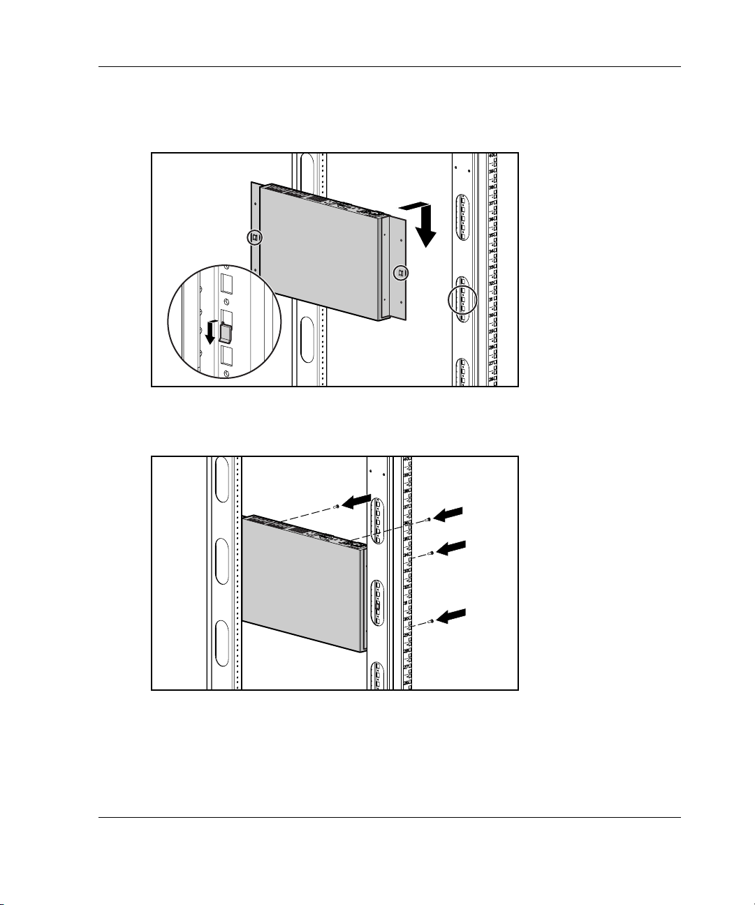
2. Slide the tabs on the side-mounting brackets into the same U location on each
side of the rack.
6
1
5
1
4
1
3
1
2
1
1
1
0
1
9
8
7
6
5
4
3
2
1
Figure 2-2: Sliding the tabs into the rack
3. Secure the console switch to the rack frame, using two screws on each side.
6
1
5
1
4
1
3
1
2
1
1
1
0
1
9
8
7
6
5
4
3
2
1
Figure 2-3: Securing the console switch
HP IP Console Switch User Guide 2-5
Page 23
Installing the IP Console Switch
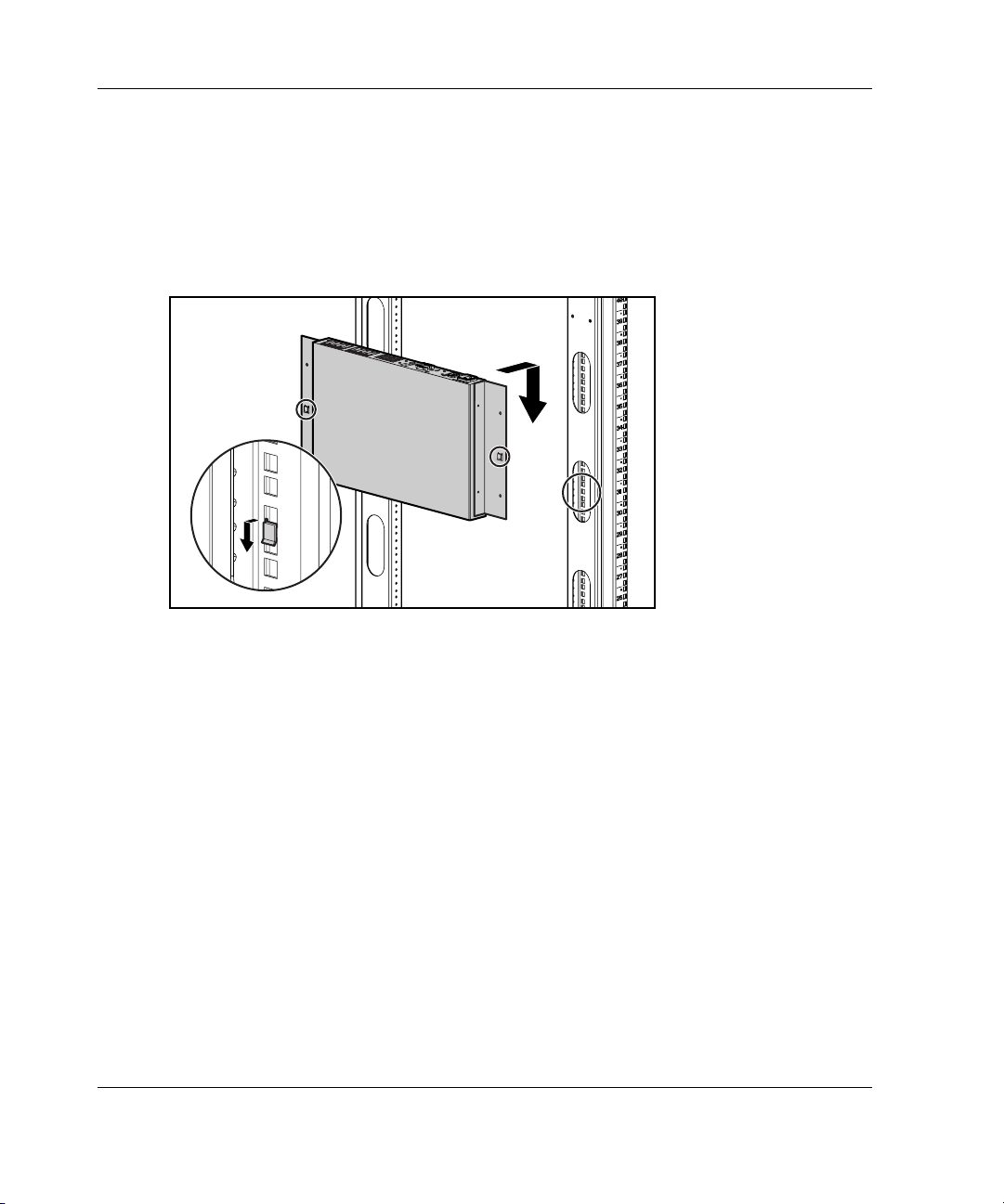
Type B
1. Attach the side-mounting brackets to the console switch, using two screws on
each side.
2. Slide the tabs on the side-mounting brackets into the same U location on each
side of the rack.
6
5
1
Figure 2-4: Sliding the tabs into the rack
1
4
1
3
1
2
1
1
1
0
1
9
8
7
6
5
4
3
2
1
2-6 HP IP Console Switch User Guide
Page 24
Installing the IP Console Switch
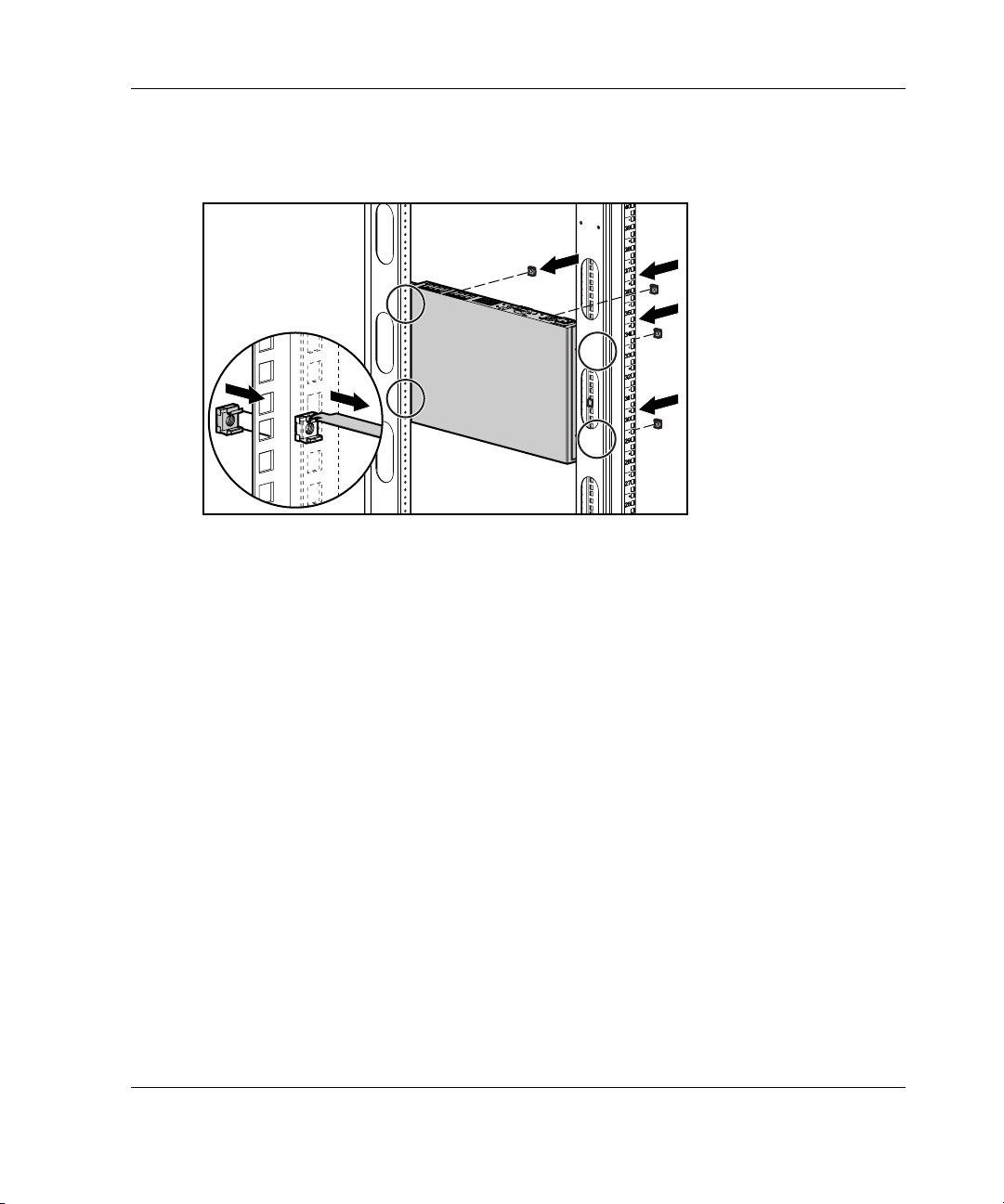
3. Insert four cage nuts into the rack frame in the location of the side-mounting
bracket holes.
6
1
5
1
4
1
3
1
2
1
1
1
0
1
9
8
7
6
5
4
3
2
1
Figure 2-5: Inserting cage nuts
4. Secure the console switch to the rack frame, using two screws on each side.
HP IP Console Switch User Guide 2-7
Page 25
Installing the IP Console Switch
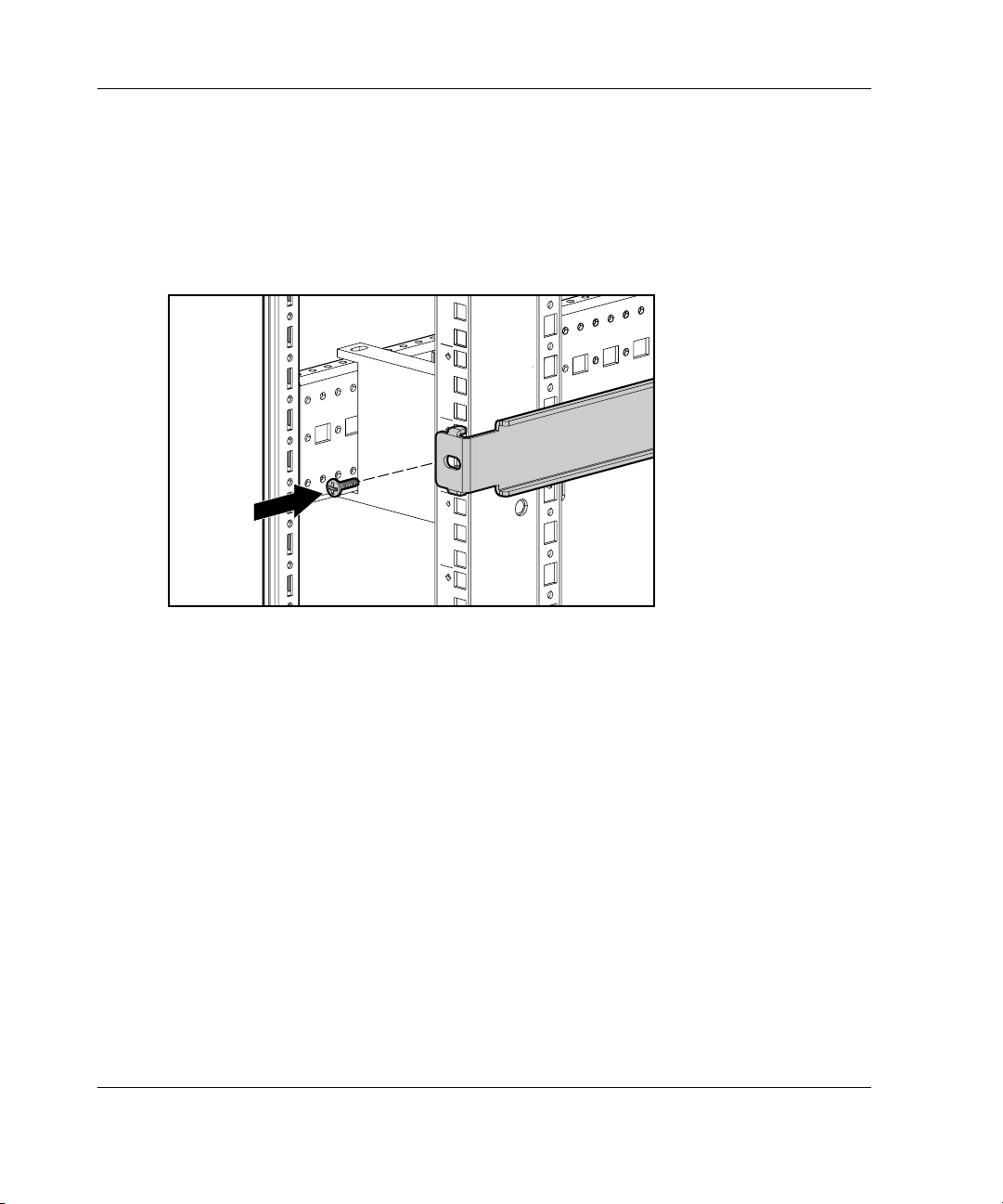
Using Rear Rack Installation
IMPORTANT: If you are installing a console switch with a 1U component, such as the 1U
Keyboard Drawer Rack Option Kit, additional rack space is not required, making it a
0U installation.
To install the IP Console Switch in the rear of the rack:
1. Attach the slide rail brackets to the console switch, using two screws on
each slide.
1
0
0
2
4
0
V
,
1
.
0
A
,
5
0
/
6
0
H
z
T
2
A
,
2
5
0
V
A
C
C
A
U
T
I
O
N
:
For continued protection against risk of fire, replace only with same type and rating of fuse.
1
3
2
5
4
6
7
8
9
1
1
1
0
1
3
1
2
1
5
1
4
1
6
Figure 2-6: Attaching the slide rail brackets
2-8 HP IP Console Switch User Guide
Page 26
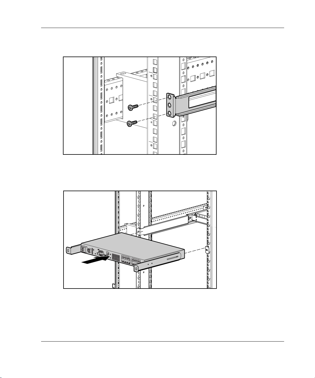
Installing the IP Console Switch
2. If a cage nut is not already installed behind the rear rail, install one at this time.
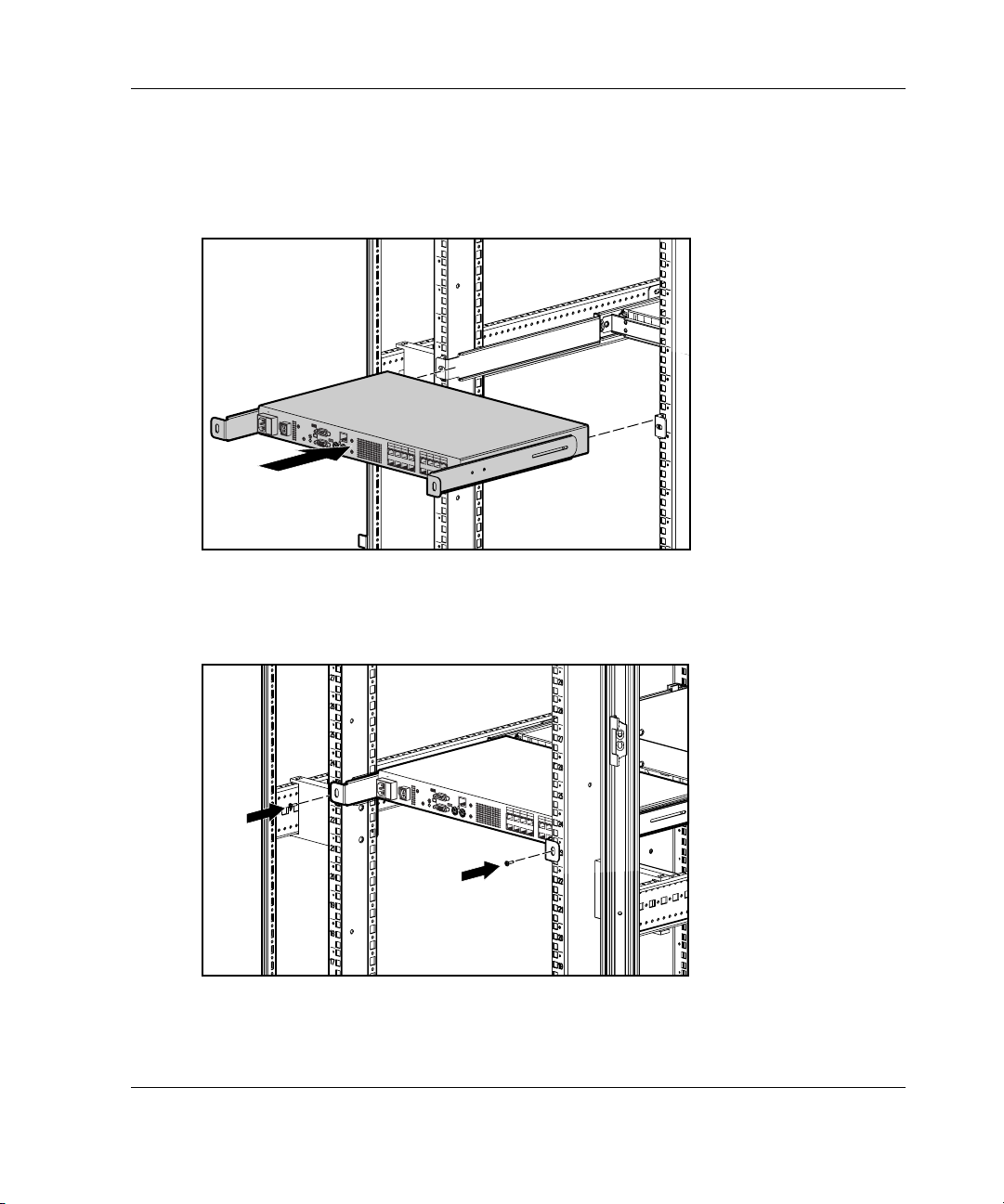
3. Slide the console switch, with the slide rail brackets, into the rail-mounting
brackets already installed in the rack.
100-240V
, 1.0A, 50/60 Hz
T 2A, 250 VAC CAU
TION:
F
o
r
c
o
n
t
in
u
e
d
pr
o
te
c
ti
o
n
a
g
a
i
n
s
t
r
is
k
o
f
fir
e
,
re
p
l
a
c
e
o
n
ly
w
it
h
s
a
m
e
ty
p
e
a
n
d
ra
t
in
g
o
f
fu
1
3
2
5
4
7
s
e
.
6
8
9
11
10
13
12
15
14
16
Figure 2-7: Sliding the console switch into the rack
4. Secure the slide rail brackets to the rear of the rack, using two screws on
each side.
1
0
0
-2
4
0
V
, 1
.
0
A
,
5
0
/6
0
H
z
T
2
A
,
2
5
0
V
A
C
C
A
U
T
IO
N
:
F
o
r
c
o
n
t
i
n
u
e
d
p
r
o
t
e
c
t
i
o
n
a
g
a
i
n
s
t
r
i
s
k
o
f
f
i
r
e
,
r
e
p
l
a
c
e
o
n
l
y
w
i
t
h
s
a
m
e
t
y
p
e
a
n
d
r
a
t
i
n
g
o
f
f
u
1
3
2
5
4
7
s
e
.
6
8
9
1
1
1
0
1
3
1
2
1
5
1
4
1
6
Figure 2-8: Securing the slide rail brackets to the rack
HP IP Console Switch User Guide 2-9
Page 27
Installing the IP Console Switch
Using Standard 1U Installation
To install the console switch:
1. Attach the slide rail brackets to the console switch, using the two screws on
each side.
2. Use the template that was shipped with the component to mark the location of the
mounting hardware.
a. Push back the tabs (marked Õ) on the top of the template, and place them in
the correct holes in the mounting rails.
Figure 2-9: Measuring with the rack template
b. Match up the hole pattern, indicated on the sides of the template, with the
hole pattern on the mounting rails.
c. Measuring from the top of the component immediately below the new
component, place the template against the front and rear of the rack frame to
mark the attachment points for the mounting rails and rear cage nuts.
2-10 HP IP Console Switch User Guide
Page 28
Installing the IP Console Switch
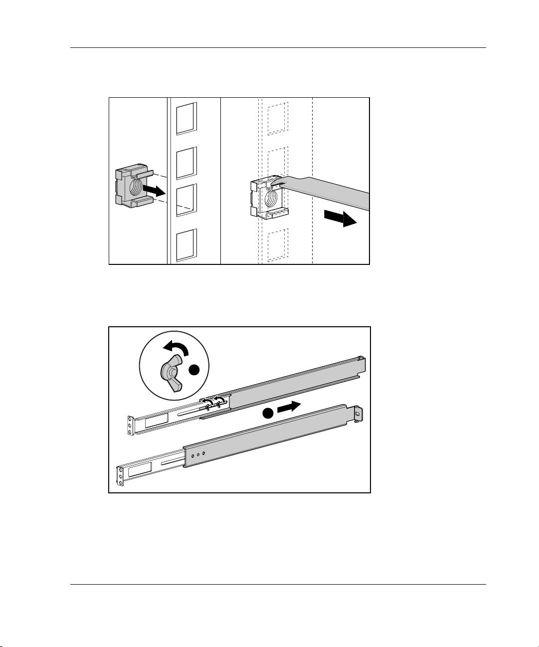
3. Install two cage nuts into the holes marked by the template at the rear of the rack.
Figure 2-10: Installing cage nuts
4. Loosely attach the wing nuts (1), and extend the adjustable rail-mounting
brackets to the desired length (2).
1
2
Figure 2-11: Adjusting rails
HP IP Console Switch User Guide 2-11
Page 29
Installing the IP Console Switch
5. Tighten the wing nuts slightly to stabilize the adjustable rails during installation.
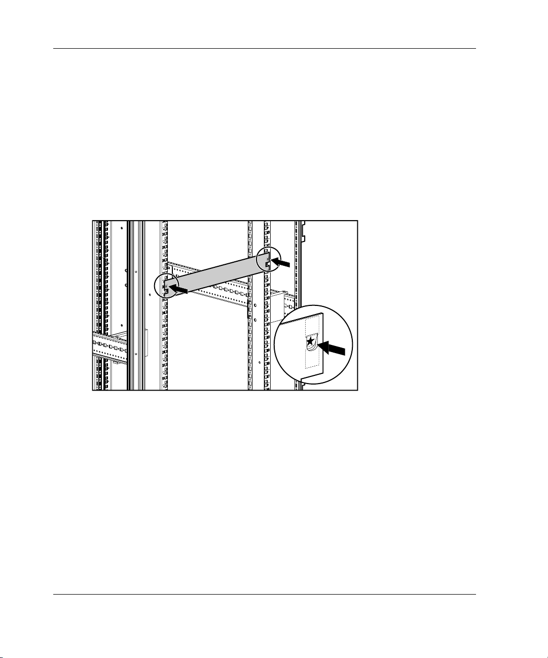
6. Insert an adjustable rail into the rack, and hook the tabs into the appropriate holes
at the rear of the rack, aligning the screws holes at the front of the rack.
7. Secure the rear of the adjustable rail, using one screw for each cage nut
previously installed.
Figure 2-12: Securing the adjustable rail
2-12 HP IP Console Switch User Guide
Page 30
Installing the IP Console Switch
8. Secure the front of the adjustable rail to the rack, using two screws for each rail.
Figure 2-13: Securing the adjustable rail
9. Slide the console switch into the adjustable rails, and secure it to the rear of the
rack, using one screw on each side.
100-240V
, 1.0A, 50/60 Hz
T 2A, 250 VAC CAUTION:
F
o
r c
o
n
tin
u
e
d
p
r
o
te
c
tio
n
a
g
a
in
s
t ris
k
o
f fire
, r
e
p
la
c
e
o
n
ly
w
ith
s
a
m
e
ty
p
e
a
n
d
ra
tin
g
o
f fu
1
3
2
5
4
7
s
e
.
6
8
9
11
10
13
12
15
14
16
Figure 2-14: Securing the console switch into the rack
HP IP Console Switch User Guide 2-13
Page 31

Installing the IP Console Switch
10. Position the front cover panel, and secure it to the front of the rack, using one
screw on each side.
100-24
0V
, 1.0A
, 50/60
H
z
T 2A
, 250 V
AC CAUT
ION
:
Figure 2-15: Positioning the front cover panel
Configuring the IP Console Switch Hardware
To configure the IP Console Switch hardware:
1. Connect one end of a serial cable to an available COM port on the server that is
to be viewed locally from the IP Console Switch.
2. Connect the other end of the serial cable to the serial port on the
IP Console Switch.
3. Plug the supplied power cord in to the rear of the IP Console Switch and then in
to a valid power source.
4. Power on the IP Console Switch. The activity indicator on the rear panel powers
on. The activity indicator blinks for 30 seconds while performing a self-test.
Approximately 10 seconds after it stops blinking, press the Enter key to access
the main menu.
2-14 HP IP Console Switch User Guide
Page 32

Installing the IP Console Switch
5. Configure the terminal emulation software for the server, such as HyperTerminal
for Microsoft
®
Windows® operating systems or Minicom for Linux operating
systems.
To configure HyperTerminal:
a. From the desktop screen, click Start, Programs, Accessories,
Communications, HyperTerminal. The Connection Description window
is displayed.
b. Enter a name for the description, and click OK. The Connect To window
is displayed.
c. Select the Communication Port that is connected to the KVM switch
through a serial cable, then click OK. The COM1 Properties window
is displayed.
d. Select 9600 for the Bits Per Second, 8 for Data Bits, None for Parity, 1 for
Stop Bits, and None for Flow Control, then click OK. The HyperTerminal
auto-connects to the console switch.
e. Press the Enter key to access the console switch option menu.
To configure Minicom:
IMPORTANT: Minicom is a utility that is loaded during the installation of Red Hat 7.2 and
7.3. However, if you do not select the option to install the Linux Utilities during the
operating system installation, you are not able to use Minicom without downloading the
Minicom 1.831-16.i386.rpm file from the Red Hat website. (Refer to the procedure for
installing RPMs on the Red Hat website).
a. Log on to a Linux console, or open a terminal and enter minicom-s at the
command prompt. The Configuration menu is displayed.
b. Select Serial Port Setup. The Change which setting? menu is displayed.
c. Select Option A (Serial Device). Manually change the device type from
“dev/modem” to “/dev/ttyS0” and press the Enter key.
d. Select Option E (Bps/Par/Bits). The Comm Parameters menu is displayed.
e. Select E (Speed 9600 Bps), and press the Enter key. The designation
9600 8N1 is displayed next to Option E.
HP IP Console Switch User Guide 2-15
Page 33

Installing the IP Console Switch
f. Select Option F (Hardware Flow Control).
Be sure that the Change which setting? menu is configured as follows:
A—Serial Device: /dev/ttyS0
B—Lockfile Location: /var/lock
C—Callin Program:
D—Callout Program:
E—Bps/Par/Bits: 9600 8N1
F—Hardware Flow Control: No
G—Software Flow Control: No
g. Press the Enter key to return to the Configuration menu. Scroll down to the
Save setup as dfl option, and press the Enter key.
h. Scroll down the Configuration menu to the Exit from Minicom option, and
press the Enter key.
2-16 HP IP Console Switch User Guide
Page 34

Installing the IP Console Switch
i. From the Linux Red Hat 7.2 and 7.3 command prompt, enter Minicom. As
soon as a connection is established, the Main menu for the IP Console
Switch is displayed. Follow the on-screen options to configure the IP
Console Switch. The IPViewer HyperTerminal menu with six options
is displayed.
Figure 2-16: IPViewer HyperTerminal menu
HP IP Console Switch User Guide 2-17
Page 35

Installing the IP Console Switch
6. Select Option 1—Network Configuration. The Network Configuration menu
is displayed.
Figure 2-17: Network Configuration menu
7. Select Option 1 to set the network speed. When possible, set the connection
manually without relying on the auto negotiate feature. After you enter your
selection, you return to the Network Configuration menu.
8. Select Option 2 to specify a static or BootP IP address. Use a static IP address
for ease of configuration. If you are using a BootP address, configure your BootP
server to provide an IP address to the console switch, omit step 9, and continue to
the next procedure.
9. Select Option 3 through 5 from the Terminal Applications menu to finish
configuring the console switch for an IP address, Netmask, and Default Gateway.
When this configuration is complete, enter 0 to return to the IPViewer
HyperTerminal menu.
2-18 HP IP Console Switch User Guide
Page 36

Adjusting the Mouse Acceleration
Before a server can connect to the IP Console Switch, an adjustment to the mouse
acceleration must be made. Use the default Microsoft Windows PS/2 mouse driver
for all attached Microsoft Windows systems attached to the console switch.
NOTE: To ensure optimum mouse performance, refer to the “Setting the Mouse Scaling” and
“Aligning and Resetting the Mouse” sections in the HP IP Console Switch Software Guide,
included on the Rack Products Documentation CD.
For Windows operating systems (default drivers):
1. From the desktop, select Start, Settings, Control Panel, and double-click the
Mouse icon.
2. Select the Motion tab.
3. For Windows NT, set Pointer Speed to Slow and the Acceleration setting
to None.
-or-
For Windows 2000, set the Speed setting to 50% (default) and the Acceleration
setting to None.
Installing the IP Console Switch
-or-
For Windows XP, set the set the Speed setting to 50% (default) and the
Acceleration setting the 6
th
position from the far left.
For Linux operating systems:
1. From the GNOME desktop, click main menu.
2. From the main menu task list, select Programs, Settings, Peripherals.
3. From the Peripherals task list, select Mouse. The Mouse Configuration window
is displayed. In this window, you can set the mouse to be either right-handed or
left-handed, and adjust the mouse motion by changing the threshold and
adjusting the acceleration to the 4
HP IP Console Switch User Guide 2-19
th
position from the far left.
Page 37

Installing the IP Console Switch
Adding Servers
Although you configure the entire IP Console Switch system through either the OSD
or the IP Console Viewer, HP recommends first adding server names to the OSD at
the local analog station, before to adding or discovering the console switch in the IP
Console Viewer at the digital station.
To add server names:
1. Launch the OSD at the local analog station, and input all server names. You can
also customize the OSD, as well as access the IP Console Switch from the analog
station. For detailed instructions on OSD setup and configuration, refer to
Chapter 6 in this guide.
2. After you install the IP Console Viewer on each digital station, launch the
IP Console Viewer and click Add Console Switch to add the new IP Console
Switch. The server names you entered in the OSD now are displayed in the IP
Console Viewer for all servers and Interface Adapters that are powered online.
The Interface Adapters that are offline can be added later using the
Resync feature.
For more information, refer to the HP IP Console Switch Software Guide, included
with your console switch.
2-20 HP IP Console Switch User Guide
Page 38

An optional Expansion Module can be added to the IP Console Switch system,
enabling access for up to 8 servers on each port, increasing the total number of
accessible servers to 128.
Features
The features of the Expansion Module include:
• Connection to an IP Console Switch through a single UTP CAT5 cable
• Connection to each Interface Adapter through a single UTP CAT5 cable
• Connections for eight Interface Adapters
• An active KVM connection between one IP Console Switch port and one
Interface Adapter at a time
3
Expansion Module
• No external power required
• Ability to mount along the sides or along the rear of standard 19-inch internal
mounting rails
HP IP Console Switch User Guide 3-1
Page 39

Expansion Module
1
2
100-24
0V
, 1.0A, 50/60 Hz
T 2A, 250 VA
C CA
UTION:
F
o
r
c
o
n
t
i
n
u
e
d
p
r
o
t
e
c
t
i
o
n
a
g
a
i
n
s
t
r
i
s
k
o
f
f
ir
e
,
r
e
p
l
a
c
e
o
n
l
y
w
i
t
h
s
a
m
e
t
y
p
e
a
n
d
r
a
t
i
n
g
o
f
f
u
s
e
.
1
3
2
5
4
7
6
8
9
11
10
13
12
15
14
16
3
4
5
6
Figure 3-1: Example of an IP Console Switch
configuration with an Expansion Module
Item Description
1 IP Console Switch
2 Expansion Module
3 Interface Adapter
4 Video connector
5 Keyboard connector
6 Mouse connector
3-2 HP IP Console Switch User Guide
Page 40

Installing the Expansion Module Hardware
Performing a Side-Mount Installation
To side mount an Expansion Module to the rack:
1. Slide the tabs on the side-mounting brackets into the rack frame.
Expansion Module
Figure 3-2: Sliding the tabs into the rack
HP IP Console Switch User Guide 3-3
Page 41

Expansion Module
2. Secure the Expansion Module to the rack frame, using one self-tapping screw for
the bottom side-mounting bracket.
Figure 3-3: Inserting screw
3-4 HP IP Console Switch User Guide
Page 42

Performing a Rail-Mount Installation
To rail mount an Expansion Module to the rack:
1. Remove screws securing the side-mounting brackets to the Expansion Module.
Figure 3-4: Removing screws
Expansion Module
HP IP Console Switch User Guide 3-5
Page 43

Expansion Module
2. Position the Expansion Module, and insert two cage nuts into the rack frame
where the mounting bracket holes are located (1). Secure the Expansion Module
to the rack frame, using two M-6 screws (2).
2
2
Figure 3-5: Installing the Expansion Module
1
1
3-6 HP IP Console Switch User Guide
Page 44

Performing a Velcro-Mount Installation
To Velcro mount an Expansion Module to the rack:
1. Determine the location for the Expansion Module.
2. Remove the protective strip (1) from the Velcro, and attach it to the Expansion
Module.
3. Remove the protective strip (1) from the other side of the Velcro, and attach it to
the rack frame (2).
Expansion Module
1
2
1
Figure 3-6: Velcro-mounting the Expansion Module
HP IP Console Switch User Guide 3-7
Page 45

Expansion Module
Installing the Expansion Module into the IP Console Switch System
To install an optional Expansion Module into the IP Console Switch system:
1. Mount the Expansion Module into the rack, using one of the previously described
methods.
2. Locate up to nine UTP CAT5 cables.
3. Connect one end of a UTP CAT5 cable to the desired port on the rear panel of
the IP Console Switch.
4. Attach the other end of the UTP CAT5 cable to the IN port on the Expansion
Module.
5. Connect one end of another UTP CAT5 cable to the OUT port on the
Expansion Module.
6. Attach the other end of the second UTP CAT5 cable to the Interface Adapter.
7. Repeat steps 5 through 6 to connect any other servers.
3-8 HP IP Console Switch User Guide
Page 46

An optional Interface Adapter can be added to the IP Console Switch system,
connecting UTP CAT5 cables to standard VGA video and PS/2 connections.
Features
The features of an Interface Adapter include:
• Connection to an IP Console Switch through a single UTP CAT5 cable
• Reduction of cable bulk
• No external power required
• Compatible with Compaq legacy console switches
• Keep Alive functionality, enabling continuous mouse and keyboard data activity
to attached servers, even when the IP Console Switch is powered off
4
Interface Adapters
• Ability to identify Interface Adapter ID or EID from local or remote access
HP IP Console Switch User Guide 4-1
Page 47

Interface Adapters
1
1
00-240V
, 1.0A, 50/60 H
z
T 2A, 250 VA
C C
AUT
ION:
F
o
r
c
o
n
t
i
n
u
e
d
p
r
o
t
e
c
t
io
n
a
g
a
i
n
s
t
r
i
s
k
o
f
f
ir
e
,
r
e
p
l
a
c
e
o
n
l
y
w
it
h
s
a
m
e
t
y
p
e
a
n
d
r
a
t
i
n
g
o
f
f
u
s
e
1
3
2
5
4
7
.
6
8
9
11
10
1
3
1
2
15
14
16
2
3
4
Figure 4-1: IP Console Switch configuration with an
Interface Adapter
Item Description
1 IP Console Switch
2 Interface Adapter
3 Video connector
4 Keyboard connector
5 Mouse connector
5
4-2 HP IP Console Switch User Guide
Page 48

Connecting an Interface Adapter to the IP Console Switch System
To connect an Interface Adapter to each server:
1. Locate the Interface Adapter.
2. Attach the appropriate color-coded connectors on the Interface Adapter to the
KVM ports on the server that connects to the IP Console Switch.
3. Connect one end of a UTP CAT5 cable to the desired port on the rear panel of
the IP Console Switch.
4. Connect the other end of the UTP CAT5 cable to the RJ-45 connector on the
Interface Adapter.
5. Repeat the steps 1 through 4 for all servers.
Interface Adapters
HP IP Console Switch User Guide 4-3
Page 49

5
Cascade Console Switches
The IP Console Switch enables Compaq legacy console switches to be cascaded in
the IP Console Switch system. Compatible models include:
• 1 x 4 [PN: 400336 (-001)(-291)(-B31)]
• 1 x 8 [PN: 400337 (-001)(-291)(B-31)]
• 2 x 8 [PN: 400338 (-001)(-291)(B-31)]
• 2 x 8 48VDC [PN: 400542-B21]
IMPORTANT: All Compaq legacy console switches must be upgraded with SoftPaq firmware,
version 2.1.0 or later. If you do not upgrade the legacy console switches, the IP Console
Switch system will not recognize them.
The IP Console Switch system supports only one level of cascading. To be sure that
the equipment performs at optimum levels, follow proper power-on sequences while
cascading console switches.
IMPORTANT: An Expansion Module is considered a level of cascading and, therefore, cannot
be used in combination with a cascaded Compaq legacy console switch.
HP IP Console Switch User Guide 5-1
Page 50

Cascade Console Switches
Figure 5-1: Example of an IP Console Switch system
with tiering
Item Description
1
10
0-2
40V
,
1.0
A
,
5
0/60
H
z
T 2
A
,
2
50 V
A
C
CAU
T
I
O
N
:
F
o
r
c
o
n
t
i
n
u
e
d
p
r
o
t
e
c
ti
o
n
a
g
a
i
n
s
t
r
i
s
k
o
f
f
ir
1
e
,
r
e
p
l
a
c
e
o
3
n
l
y
w
2
i
t
h
s
a
m
5
e
t
y
4
p
e
a
n
7
d
r
a
ti
6
n
g
o
f
f
u
s
e
.
8
9
11
10
13
12
15
1
4
1
6
2
6
3
4
5
1 IP Console Switch
2 Interface Adapter
3 Video connector
4 Keyboard connector
5 Mouse connector
6 Compaq legacy console switch
5-2 HP IP Console Switch User Guide
Page 51

Cascade Console Switches
Connecting Cascade Switches to the IP Console Switch System
NOTE: You cannot access any servers on a cascaded Compaq legacy console switch
remotely from the IP Console Viewer unless the IP Console Switch is in Free Mode. Free
Mode can be achieved by pressing the Alt + 0 keys from the Main menu. If the IP Console
Switch is not in Free Mode, the following message is displayed: <server name> is not
available for viewing, Reason: Channel In Use By Local User.
To connect a cascade switch (optional) to the IP Console Switch system:
1. Mount the console switch the rack. Locate a UTP CAT5 cable to connect your
console switch to the Interface Adapter for your console switch.
2. Attach one end of a UTP CAT5 cable to the RJ-45 connector on the
Interface Adapter.
3. Connect the other end of the UTP CAT5 cable to the desired port on the rear
panel of the console switch.
4. Attach the keyboard, monitor, and mouse connectors of the Interface Adapter to a
user port on your cascaded console switch.
5. Connect the servers to the cascade switch, according to the cascade
switch instructions included with that console switch.
6. Power on the console switch to enable the cascade code.
7. Repeat steps 1 through 6 for any other console switches you want to add to the
IP Console Switch system.
Cascading 2 x 8 Compaq Legacy Console Switches into the IP Console Switch System
When connecting to a Compaq legacy 2 x 8 console switch, it is important to only
connect one Interface Adapter to the console switch at any given time. If multiple
Interface Adapters are attached, undesirable operation can occur.
HP IP Console Switch User Guide 5-3
Page 52

Local Port Operation
The IP Console Switch has a local port on the rear panel that enables the user to
connect a KVM to the console switch for direct access. The IP Console Switch also
uses an OSD that enables the user to configure the system.
Viewing and Selecting Ports and Servers
Use the OSD Main dialog box to view, configure, and control servers in the
IP Console Switch system. You can also view your servers by name, port, or by the
unique EID embedded in each Interface Adapter. When the OSD is first launched, an
OSD-generated port list is displayed by default.
The Port column indicates the port to which a server is connected. If you connect a
legacy KVM console switch to the console switch, the port numbering displays the
port then the console switch port to which the server is connected.
6
HP IP Console Switch User Guide 6-1
Page 53

Local Port Operation
Accessing the Main Dialog Box
To access the Main dialog box:
Press the Print Scrn key. The Main dialog box is displayed.
NOTE: You can also press the Ctrl key twice within one second to launch the OSD. You can
use this key sequence in any place you see Print Scrn throughout this user guide.
Figure 6-1: Main dialog box
6-2 HP IP Console Switch User Guide
Page 54

Viewing the Status of your IP Console Switch System
The status of the servers in your system is indicated in the right column of the
Main dialog box.
Table 6-1: OSD Status Symbols
Item Description
(green circle) Interface Adapter is connected or powered on.
Interface Adapter is not connected or is powered off.
Interface Adapter is tiered to another console switch and is not
connected or is powered off.
Interface Adapter is tiered to another console switch and is
connected or powered on.
(yellow circle) Interface Adapter is being upgraded.
A symbol that identifies which console switch is being used.
Local Port Operation
HP IP Console Switch User Guide 6-3
Page 55

Local Port Operation
Selecting Servers
From the Main dialog box, users can select specific servers. When a new server is
selected, the IP Console Switch reconfigures the KVM to the settings for the
selected server.
To select servers:
Double-click server Name, EID, or Port number.
NOTE: The EID is an electronic identification number, found on the Interface Adapter cable
label, automatically assigned to the Interface Adapter.
-or-
If the display order of the server list is by port (the Port button is selected), enter the
Port number and press the Enter key.
-or-
If the display order of the server list is by Name or EID number (the Name or EID
button is selected), enter the first few letters of the Name of the server or the EID
number to establish it as unique, and then press the Enter key.
Selecting Previous Servers
To select previous servers:
Press the Print Scrn key, then press the Backspace key. This key combination
toggles between the previous and current connection.
Disconnecting Users from a Server
To disconnect from a server:
Press the Print Scrn key, then press the Alt + 0 keys. This leaves no server selected
and in a free state. The status flag on the OSD displays Free.
6-4 HP IP Console Switch User Guide
Page 56

Soft Switching
Soft switching is the ability to switch servers, using a hotkey sequence. You can soft
switch to a server by pressing the Print Scrn key and entering the first few characters
of its name or number. If you have set a Screen Delay Time and you press the key
sequences before that time has elapsed, the OSD does not display.
Configuring Servers for Soft Switching
To configure servers for soft switching:
1. Press the Print Scrn key. The Main dialog box is displayed.
2. Click Setup. The Setup dialog box is displayed.
3. Click Menu. The Menu dialog box is displayed.
4. For Screen Delay Time, enter the number of seconds of delay desired before the
Main dialog box displays after the Print Scrn key is pressed.
5. Click OK.
Local Port Operation
Soft Switching Servers
To soft switch servers:
1. To select a server, press the Print Scrn key. If the display order of your server
list is by port (the Port button is selected), enter the Port number and press the
Enter key.
-or-
If the display order of the server list is by Name or EID number (the Name or
EID button is selected), enter the first few letters of the Name of the server or the
EID number to establish it as unique, and then press the Enter key.
2. To switch back to the previous server, press the Print Scrn key, then press the
Backspace key.
HP IP Console Switch User Guide 6-5
Page 57

Local Port Operation
Using Basic OSD Navigation
The following table describes the keyboard and mouse OSD navigation keys.
Table 6-2: OSD Navigation Keys
Keystroke Function
Print Scrn Opens the OSD. Press the
Print Scrn key twice to send the
Print Scrn keystroke to the
currently selected device.
F1
Esc Closes the current dialog box
Alt When used in combination with the
Alt + X Closes the current dialog box and
Alt + 0
Enter Completes the console switch
Single-Click, Enter In a text box, selects the text for
Opens the Help screen for the
current dialog box.
without saving changes and returns
to the previous dialog box. In the
Main dialog box, it closes the OSD
and returns to the selected server.
In a message box, it closes the popup box and returns to the current
dialog box.
other keys, opens dialog boxes,
selects options, and executes
actions.
returns to the previous dialog box.
Selects the OK button and returns
to the previous dialog box.
operation in the Main dialog box
and exits the OSD.
editing and enables the left and right
arrow keys to move the cursor.
Press the Enter key again to quit
Edit mode.
continued
6-6 HP IP Console Switch User Guide
Page 58

Local Port Operation
Table 6-2: OSD Navigation Keys continued
Keystroke Function
Print Scrn, Backspace Toggles back to the previous
selection if no other keystrokes
have been entered.
Print Scrn, Alt + 0 Immediately disengages user from a
server—no server is selected.
Status Flag displays Free. (This
only applies to the 0 on the
keyboard, not the keypad.)
Print Scrn, Pause Immediately activates the screen
saver mode and prevents access to
that particular console, if it is
password protected.
Up/Down Arrows Moves the cursor from line to line.
Right/Left Arrows Moves the cursor between columns.
When editing a text box, these keys
move the cursor within the column.
Page Up/Page Down Pages up and down through Name
and Port lists.
Home/End Moves the cursor to the top or
bottom of a list.
Backspace Erases characters in a text box.
Delete Deletes current selection in the
Scan dialog box or characters in a
text box.
Shift + Delete Deletes from current selection to all
lines below it when editing a
scan list.
Numbers Entered from the keyboard or
keypad.
Caps Lock
Disables user. (Use the Shift key to
change case.)
HP IP Console Switch User Guide 6-7
Page 59

Local Port Operation
Configuring the OSD Setup Menu
You can configure the IP Console Switch from the Setup menu within the OSD.
Select the Names button when initially setting up your console switch to identify
servers by unique names. Select the other setup features to manage routine tasks for
your servers from the OSD menu.
Table 6-3: Features to Manage Routine Tasks for Servers
Button Function
Menu Changes the server listing between
numerically by Port or EID number
and alphabetically by name.
Flag Changes the display, timing, color,
Broadcast Simultaneously controls multiple
Scan Sets up custom scan patterns for up
Security Sets password to restrict server
Enables the screen saver.
Devices Identifies device types attached to
Names Identifies servers by unique names.
Changes the Delay Time before the
Main dialog box displays after
pressing the Print Scrn key.
and location of the status flag.
servers through keyboard and
mouse actions.
to 16 servers.
access and enables screen saver.
A valid password must be
alphanumeric and contain a
minimum of 5 characters and a
maximum of 15 characters.
Permitted characters are casesensitive and can consist of A–Z, 0–
9, spacebar, and hyphen.
the console switch, including
servers and other switches.
6-8 HP IP Console Switch User Guide
Page 60

Accessing the Setup Menu
To access the Setup menu:
1. Press the Print Scrn key. The Main dialog box is displayed.
2. Click Setup. The Setup dialog box is displayed.
Local Port Operation
Figure 6-2: Setup dialog box
HP IP Console Switch User Guide 6-9
Page 61

Local Port Operation
Assigning Server Names
Use the Names dialog box to identify individual servers by name rather than by port
number. The Names list is always sorted by port order, and the names are stored in
the Interface Adapter. If you move the Interface Adapter or server to another switch
port, the IP Console Switch recognizes the names and configurations.
NOTE: If a server is powered off, its respective Interface Adapter is not displayed in the
Names list.
Accessing the Names Dialog Box
To access the Names dialog box:
1. Press the Print Scrn key. The Main dialog box is displayed.
2. Click Setup, Names. The Names dialog box is displayed.
NOTE: If the server list has changed since it was last displayed, the mouse cursor turns
into an hourglass as the list automatically updates. No mouse or keyboard input is
accepted until the list update is complete.
Figure 6-3: Names dialog box
6-10 HP IP Console Switch User Guide
Page 62

Assigning Names to Servers
To assign names to servers:
1. Press the Print Scrn key. The Main dialog box is displayed.
2. Click Setup, Names. The Names dialog box is displayed.
3. Select the name or port number, and click Modify. The Name Modify dialog
box is displayed.
Local Port Operation
Figure 6-4: Name Modify dialog box
HP IP Console Switch User Guide 6-11
Page 63

Local Port Operation
4. Enter a name in the New Name field. Names can be 1 to 15 characters in length.
Permitted characters are case-sensitive and can consist of A–Z, 0–9, spacebar,
and hyphen.
5. Click OK to transfer the new name to the Names dialog box. Changes made to
the Names dialog box are not saved until you click OK.
6. Repeat steps 3 through 5 for each server in the system.
7. Click OK in the Names dialog box to save your changes.
-or-
Click X to exit, or press the ESC key to exit the dialog box without
saving changes.
Assigning Device Types
While the console switch automatically discovers cascade switches attached to your
unit, you must specify the number of ports on the cascade switch through the Devices
dialog box.
6-12 HP IP Console Switch User Guide
Page 64

Accessing Devices Dialog Box
To access the Devices dialog box:
1. Press the Print Scrn key. The Main dialog box is displayed.
2. Click Setup, Devices. The Devices dialog box is displayed.
NOTE: The Modify button is only available if a configurable switch is selected.
Local Port Operation
Figure 6-5: Devices dialog box
When the IP Console Switch discovers a cascaded switch, the port numbering
changes to accommodate each server under that switch. For example, if the switch is
connected to port 2, the switch port is listed as 02, and each server under it is
numbered sequentially 02-01, 02-02, and so on.
HP IP Console Switch User Guide 6-13
Page 65

Local Port Operation
Assigning Device Types
To assign a device type:
1. In the Devices dialog box, select the Port number.
2. Click Modify. The Device Modify dialog box is displayed.
3. Choose the number of ports supported by the cascaded console switch.
4. Click OK.
5. Repeat steps 2 through 4 for each port the user wants to assign a device type.
6. Click OK in the Devices dialog box to save settings.
NOTE: Changes made in the Device Modify dialog box are not saved until you click OK
in the Devices dialog box.
Figure 6-6: Device Modify dialog box
6-14 HP IP Console Switch User Guide
Page 66

Changing the Display Behavior
From the Menu dialog box, the display order of servers, switch connection mode,
and a time to delay display of the OSD after pressing the Print Scrn key can be
changed. The display order setting alters how servers display in several screens,
including the Main, Devices, and Broadcast dialog boxes.
Accessing the Menu Dialog Box
To access the Menu dialog box:
1. Press the Print Scrn key. The Main dialog box is displayed.
2. Click Setup. The Setup dialog box is displayed.
3. Click Menu. The Menu dialog box is displayed.
Local Port Operation
Figure 6-7: Menu dialog box
HP IP Console Switch User Guide 6-15
Page 67

Local Port Operation
Selecting the Display Order of Servers
To choose the display order of servers:
1. From the Menu dialog box, select Name to display servers alphabetically
by name.
-or-
Select EID to display servers numerically by Interface Adapter ID number.
-or-
Select Port to display servers numerically by port number.
2. Click OK.
Setting Screen Delay Time
Setting a time to delay the display of the OSD enables you to complete a soft switch
without displaying the OSD. To perform a soft switch, see the “Soft Switching”
section in this chapter.
To set the Screen Delay Time for the OSD:
1. From the Menu dialog box, enter the number of seconds (0–9) the OSD is
delayed after pressing the Print Scrn key. Entering 0 instantly displays the OSD
with no delay.
2. Click OK.
6-16 HP IP Console Switch User Guide
Page 68

Controlling the Status Flag
The status flag is displayed on the desktop and shows the Name or EID number of
the selected server or the status of a particular port. Use the Flag dialog box to
change the flag display by server Name or EID number or to change the flag color,
opacity, display time, and location on the desktop.
Table 6-4: OSD Status Flags
Flag Description
Local Port Operation
Flag type by Name
Flag type by EID number
Flag indicating that the user has
been disconnected from all systems
Flag indicating that the broadcast is
activated
Control used to set flag position
HP IP Console Switch User Guide 6-17
Page 69

Local Port Operation
Accessing the Flag Dialog Box
To access the Flag dialog box:
1. Press the Print Scrn key. The Main dialog box is displayed.
2. Click Setup. The Setup dialog box is displayed.
3. Click Flag. The Flag dialog box is displayed.
Figure 6-8: Flag dialog box
6-18 HP IP Console Switch User Guide
Page 70

Displaying the Status Flag
To determine how the status flag is displayed:
1. Select Name or EID to determine what information is displayed.
2. Select Displayed to show the flag constantly or select Timed to display the flag
for only five seconds after soft switching.
3. Select a flag color in Display Color.
4. In the Display Mode, select Opaque for a solid color flag or select Transparent
to see the desktop through the flag.
5. Position the status flag on the desktop:
a. Click Set Position to gain access to the Position Flag screen.
b. Left-click and hold the title bar and drag to the desired location.
c. Right-click to return to the Flag dialog box.
Figure 6-9: Position flag screen
NOTE: Changes made to the position flag are not saved until you click OK in the Flag
dialog box.
Local Port Operation
6. Click OK to save settings.
-or-
Click X to exit without saving settings.
HP IP Console Switch User Guide 6-19
Page 71

Local Port Operation
Broadcasting to Servers
Analog users can simultaneously control more than one server in a system to be sure
that all selected servers receive identical input. For each server receiving the
broadcast, you can choose to broadcast keystrokes and/or mouse movements
independently.
NOTE: You can broadcast to only one server per Expansion Module connection.
Broadcasting Keystrokes—The keyboard statistics must be identical for all servers
receiving a broadcast to interpret keystrokes identically. Specifically, the Caps Lock
and Num Lock modes must be the same on all keyboards. While the switch attempts
to send keystrokes to the selected servers simultaneously, some servers can inhibit
and thereby delay the transmission.
Broadcasting Mouse Movements—For the mouse to work accurately, all systems
must have identical mouse drivers, desktops (such as identically placed icons), and
video resolutions. In addition, the mouse must be in exactly the same place on all
screens. Because these conditions are extremely difficult to achieve, broadcasting
mouse movements to multiple systems can have unpredictable results.
6-20 HP IP Console Switch User Guide
Page 72

Accessing Broadcast Dialog Box
To access the Broadcast dialog box:
1. Press the Print Scrn key. The Main dialog box is displayed.
2. Click Setup, Broadcast. The Broadcast dialog box is displayed.
Local Port Operation
Figure 6-10: Broadcast dialog box
HP IP Console Switch User Guide 6-21
Page 73

Local Port Operation
Broadcasting Selected Servers
To broadcast selected servers:
1. From the Broadcast dialog box, select the keyboard and mouse checkboxes for
the servers that are to receive the broadcast commands.
-or-
Press the Up or Down Arrow keys to move the cursor to the target server. Then
press the Alt + K keys to select the keyboard checkbox and/or the Alt + M keys
to select the mouse checkbox. Repeat for additional servers.
2. Click OK to save the settings and return to the Setup dialog box. Click X or
press the Esc key to return to the Main dialog box.
3. From the Commands menu, select the Broadcast Enable checkbox to activate
broadcasting.
4. From the user station, enter the information and/or perform the mouse
movements you want to broadcast.
Activating Broadcasting
To activate or deactivate broadcasting, from the Commands menu, select or deselect
the Broadcast Enable checkbox.
Setting up a Scan Pattern
In Scan mode, the console switch automatically scans port to port (server to server).
You can select up to 16 servers from a list of all servers attached to your unit. You
can display the list by either server name or EID number by clicking the appropriate
button. Selecting the checkbox beside each server to be added to the scan list creates
the scan list. The creation of a scan list does not start Scan mode. You must enable
Scan mode through the Scan Enable checkbox on the Commands dialog box.
6-22 HP IP Console Switch User Guide
Page 74

Accessing the Scan Dialog Box
To access the Scan dialog box:
1. Press the Print Scrn key. The Main dialog box is displayed.
2. Click Setup, Scan. The Scan dialog box is displayed.
Local Port Operation
Figure 6-11: Scan dialog box
HP IP Console Switch User Guide 6-23
Page 75

Local Port Operation
Adding Servers to the Scan List
To add servers to the Scan list:
1. The Scan dialog box contains a list of all the servers attached to your unit. Click
the checkbox next to the servers you want to scan.
-or-
Double-click a server name or port.
-or-
Press the Alt key plus the number of the server you want to scan. You can select
up to 16 servers.
2. In the Scan Time box, enter the number of seconds (from 3 to 99) before the
scan moves to the next server in the sequence.
3. Click OK.
NOTE: If the user removes a server from the Device Modify dialog box later, the change
can affect a custom scan pattern.
Removing Servers from the Scan List
To remove a server from the Scan list:
1. In the Scan dialog box, click the server to be removed.
-or-
Double-click a server name or port.
-or-
Click Clear to remove all servers from the scan list.
2. Click OK.
6-24 HP IP Console Switch User Guide
Page 76

Starting Scan Mode
To start the Scan mode:
1. Select Scan Enable in the Commands menu.
2. Click X to close the Commands dialog box.
NOTE: The scanning begins as soon as you click Scan.
Stopping Scan Mode
To stop Scan mode:
If the OSD is open, select a server.
-or-
If the OSD is not open, move the mouse or press any key on the keyboard. Scan
mode stops at the currently selected server.
Local Port Operation
-or-
Deselect Scan Enable in the Commands menu. Any active connections on the local
port are disconnected.
Setting Local Console Switch Security
The OSD enables you to set security on the local port consoles. You can establish a
screen saver mode that engages after the console remains unused for a user-definable
time delay. When engaged, the console remains locked until any key is pressed or the
mouse is moved. You can then enter the password to log in.
Use the Security dialog box to lock your console with password protection, set or
change the password, and enable the screen saver.
NOTE: If a password has been previously set, you must to enter the password before you can
access the Security dialog box.
HP IP Console Switch User Guide 6-25
Page 77

Local Port Operation
Accessing the Security Dialog Box
To access the Security dialog box:
1. Press the Print Scrn key. The Main dialog box is displayed.
2. Click Setup. The Setup dialog box is displayed.
3. Click Security. The Security dialog box is displayed.
Figure 6-12: Security dialog box
6-26 HP IP Console Switch User Guide
Page 78

Changing the Password
To set or change the password:
1. From the Security dialog box, single-click in the New field and press the Enter
key if the OSD is not open, or double-click the New field.
2. Enter the new password in the New field, then press the Enter key.
IMPORTANT: A valid password must be alphanumeric and be 5 to 15 characters in
length. Permitted characters are case-sensitive and can consist of A–Z, 0–9, spacebar,
and hyphen.
3. In the Repeat field, reenter the password and press the Enter key.
4. Click OK to change the password.
Setting Password Protection
To password protect your local console:
1. From the Security dialog box, set your password as described in the
previous procedure.
Local Port Operation
2. Select Enable Screen Saver.
3. Enter the number of minutes for Time Delay (from 1 to 99) to delay activation of
password protection and the screen saver feature.
®
4. For Mode, select Energy if your monitor is Energy Star
compliant. Otherwise,
select Screen.
CAUTION: Monitor damage can result from the use of energy mode with
monitors not compliant with Energy Star.
5. (Optional) Click Test to activate the screen saver test, which lasts 10 seconds and
returns you to the Security dialog box.
6. Click OK.
HP IP Console Switch User Guide 6-27
Page 79

Local Port Operation
Logging on to Switch
To log on to the IP Console Switch:
1. Press any key on the keyboard, or move the mouse. The Password dialog box is
displayed. Enter the password, then click OK.
2. Press the Print Scrn key.
Removing Password Protection
To remove the password protection from the IP Console Switch:
1. From the Main dialog box, click Setup, Security. The Password dialog box is
displayed. Enter the password, then click OK.
2. In the Security dialog box, click the New field and press the Enter key.
-or-
Double-click the New field, leave the New field blank, and press the Enter key.
3. Click the Repeat field and press the Enter key.
-or-
Double-click the Repeat field, leave the Repeat field blank, and press the
Enter key.
4. Click OK if you want to eliminate the password.
Enabling Screen Saver Mode without Password Protection
To enable the screen saver mode without password protection:
1. If your console switch does not require a password to gain access to the Security
dialog box, proceed to step 2.
-or-
If your console switch is password protected, see the previous procedure, then go
to step 2.
2. Select Enable Screen Saver.
6-28 HP IP Console Switch User Guide
Page 80

3. Enter the number of minutes for Inactivity Time (1 to 99) to delay activation of
the screen saver.
4. Select Energy if your monitor is Energy Star compliant. Otherwise,
select Screen.
CAUTION: Monitor damage can result from the use of energy mode with
monitors not compliant with Energy Star.
5. (Optional) Click Test to activate the screen saver test, which lasts 10 seconds,
then returns you to the Security dialog box.
6. Click OK.
NOTE: After activation of the screen saver mode disconnects the user from a server, no
server is selected. The status flag displays Free.
Exiting Screen Saver Mode
To exit the screen saver mode, press any key or move the mouse. The Main dialog
box is displayed.
Local Port Operation
Deactivating the Screen Saver
To activating the screen saver:
1. In the Security dialog box, clear Enable Screen Saver.
2. Click OK.
To immediately activate the screen saver, press the Print Scrn key, then press the
Pause key. This command only works when the user is connected to a server.
HP IP Console Switch User Guide 6-29
Page 81

Local Port Operation
Managing Server Tasks Using the OSD
You can manage the IP Console Switch system from the Commands menu with the
OSD, including engaging Scan and Broadcast modes, managing user connections,
running diagnostics, and updating your firmware.
Table 6-5: Commands to Manage Routine Task for your Servers
Feature Purpose
Broadcast Enable Begin broadcasting to your servers.
Configure a server list for
broadcasting under the Setup
dialog box.
Scan Enable Begin scanning your servers. Set up
a list for scanning in the Setup
dialog box.
User Status View and disconnect users.
Run Diagnostics Validate the integrity of your system,
including memory, firmware cyclic
redundant checks (CRC), comm
interfaces, switch controller, local
and remote video, and
Interface Adapters.
Interface Adapter Status Simultaneously upgrade multiple
Interface Adapters.
Reset PS/2 Reestablish operation of PS/2
keyboard and mouse
Display Versions View version information for the
console switch, as well as view and
upgrade firmware for individual
Interface Adapters.
6-30 HP IP Console Switch User Guide
Page 82

Accessing the Commands Menu
To access the Commands menu:
1. Press the Print Screen key. The Main dialog box is displayed.
2. Click Commands. The Commands dialog box is displayed.
Local Port Operation
Figure 6-13: Commands dialog box
HP IP Console Switch User Guide 6-31
Page 83

Local Port Operation
Viewing and Disconnecting User Connections
You can view and disconnect remote network users through the User Status dialog
box. The user name (U) is always displayed. However, either the server name or
Interface Adapter ID number to which the user is connected can also be displayed.
The User Status dialog box displays only the number of users the system supports. If
there are no users are currently connected to a channel, the fields are blank and the
server indicates it is free.
Viewing Current User Connections
To view current user connections:
1. Press the Print Scrn key. The Main dialog box is displayed.
2. Click Commands. The Commands dialog box is displayed.
3. Click User Status. The User Status dialog box is displayed.
6-32 HP IP Console Switch User Guide
Page 84

Disconnecting a User
To disconnect a user:
1. Press the Print Scrn key. The Main dialog box is displayed.
2. Click Commands, User Status. The User Status dialog box is displayed.
Local Port Operation
Figure 6-14: User Status dialog box
HP IP Console Switch User Guide 6-33
Page 85

Local Port Operation
3. Click the letter of the user to be disconnected. The Disconnect dialog box
is displayed.
Figure 6-15: Disconnect dialog box
4. Click OK to disconnect the user and return to the User Status dialog box.
-or-
Click X to exit, or press the Esc key to exit the dialog box without disconnecting
a user.
NOTE: If the User Status dialog box has changed since it was last displayed, the mouse
cursor becomes an hourglass as the list automatically updates. No mouse or keyboard
input is accepted until the list update is complete.
6-34 HP IP Console Switch User Guide
Page 86

Running System Diagnostics
You can validate the integrity of your system with the Run Diagnostics command.
This command checks the main board functions subsystems (memory, intra-board
communications, console switch control, and the video channels) for each system
controller. When you select Run Diagnostics, you receive a warning indicating that
all users (remote and local) will be disconnected. Click OK to confirm and begin
the test.
Running Diagnostics Test
To run diagnostics tests:
1. Press the Print Scrn key. The Main dialog box is displayed.
2. Click Commands. The Commands dialog box is displayed.
Local Port Operation
HP IP Console Switch User Guide 6-35
Page 87

Local Port Operation
3. Click Run Diagnostics. A warning message is displayed, indicating that all users
will be disconnected.
Figure 6-16: Diagnostics Warning
4. Click OK to begin.
–or-
Click X, or press the Esc key to exit the dialog box without running a
diagnostic test.
6-36 HP IP Console Switch User Guide
Page 88

Local Port Operation
5. All users are disconnected, and the Diagnostics dialog box is displayed.
Figure 6-17: Diagnostics dialog box
Test Description
Memory Test Reports the condition of the main
board RAM. This indicator displays
the results of the memory tests
performed at system reboot.
Firmware CRC Validates the current firmware
images stored in the system’s
FLASH by comparing a CRC value
on each image and comparing
those results to the expected
values.
Comm Interfaces Verifies the intra-board
communication subsystems are
accessible and functional by
querying the communications
controller and performing basic
register level tests.
continued
HP IP Console Switch User Guide 6-37
Page 89

Local Port Operation
Figure 6-17: Diagnostics dialog box continued
Test Description
Switch Controller Verifies the switch matrix controller
Local and Remote User Video Verifies that all the video channel
LAN Connection Verifies the LAN connection is
is accessible and functional by
querying the switch matrix controller
and performing basic register level
tests.
subsystems are accessible,
functional, and performing basic
register level tests.
accessible and functional by
verifying the link controller is
responsive and monitoring the
network traffic.
• If the link controller is
responsive, the test-passed
indictor is displayed.
• If the link controller is non-
responsive, the test-failed
indictor is displayed.
• If the link controller is functional
but no network traffic has been
received, an indictor
is displayed.
Online IAs Indicates the total number of
currently connected and powered
Interface Adapters.
Offline IAs Indicates the number of Interface
Adapters that have been connected
successfully in the past and are
apparently powered down.
Suspect IAs Indicates the number of Interface
Adapters that have been detected
but are either unavailable for
connection or have dropped packets
during the ping tests.
6-38 HP IP Console Switch User Guide
Page 90

Local Port Operation
6. As each test is finished, a pass or fail symbol is displayed.
A passed test is indicated with a green circle, a failed test is indicated by a red X,
and the LAN connection has a third indicator, which indicates that the LAN
connection is functional but no network traffic has been received. The test is
complete when the last test’s symbol displays.
7. (Optional) If you have any offline Interface Adapters, you can click the Clear
button to remove them from the list.
8. (Optional) If you have any suspect Interface Adapters, you can click the Display
button. The Suspect Interface Adapter dialog box is displayed.
Figure 6-18: Suspect IAs dialog box
HP IP Console Switch User Guide 6-39
Page 91

Local Port Operation
Resetting the PS/2 Mouse
If your PS/2 mouse locks up, you can re-establish operation of these peripherals by
issuing a reset command. The reset command sends a key sequence to the server,
which causes the mouse settings to be sent to the console switch. With
communication reestablished between the server and the console switch,
functionality is restored to the user.
NOTE: This function is for Microsoft Windows-based computers only. Resetting the PS/2 on a
computer running any other operating system might require that you reboot that computer.
To reset the PS/2 mouse values:
1. Press the Print Scrn key. The Main dialog box is displayed.
2. Click Commands. The Commands dialog box is displayed.
3. Click Reset PS/2. A warning is displayed.
Figure 6-19: Reset PS/2 warning
4. Click OK. A message disappears, indicating that the mouse has been reset.
5. Click X or press the Esc key to exit without sending a reset command to the
PS/2 mouse.
6-40 HP IP Console Switch User Guide
Page 92

Displaying Version Information
The Version dialog box enables you to view IP Console Viewer versions, as well as
keyboard and mouse information for the currently selected server. For optimum
performance, keep your firmware current.
NOTE: Provide the application version number, Figure 6-20, when communicating with HP
customer service centers.
To display version information:
1. Click Version in the Commands dialog box. The Version dialog box is
displayed. The top half of the box lists the subsystem versions in the
IP Console Switch.
Local Port Operation
Figure 6-20: Version dialog box
HP IP Console Switch User Guide 6-41
Page 93

Local Port Operation
2. Click Digital to view the IP Console Viewer versions. The Digital Version
dialog box is displayed. The top section identifies the digitizer subsystem
versions. The center section identifies the current network settings.
NOTE: Provide the application version number, Figure 6-20, when communicating with
HP customer service centers.
Figure 6-21: Digital Version dialog box
6-42 HP IP Console Switch User Guide
Page 94

Local Port Operation
-or-
Click IA to access the IA Selection dialog box to view individual Interface
Adapter cable version information. The IA Selection dialog box is displayed.
Figure 6-22: IA Selection dialog box
HP IP Console Switch User Guide 6-43
Page 95

Local Port Operation
3. To view the selected Interface Adapter cable, click Version. The IA Version
dialog box is displayed.
NOTE: Provide the application version number, Figure 6-19, when communicating with
HP customer service centers.
Figure 6-23: IA Version dialog box
4. Click X to exit.
6-44 HP IP Console Switch User Guide
Page 96

Upgrading Firmware using TFTP
The HP IP Console Switch FLASH upgrade feature enables you to update the
IP Console Switch with the latest available firmware.
To update the IP Console Switch, you need a Trivial File Transfer Protocol (TFTP)
server on the terminal or PC that performs upgrades. After the TFTP has been
enabled, upgrade the FLASH firmware, then upgrade the IP Console
Switch firmware.
Enabling TFTP for Windows NT
To enable TFTP for Windows NT:
1. Unzip NT_TFTP3.3.ZIP into an empty directory.
2. From the Start menu, select Settings, Control Panel.
3. Double-click Network.
7
4. Click Services and then click Add.
5. Click Have Disk.
6. In the Insert Disk box, enter the path where the extracted files are.
7. On the Select OEM Option page, click OK.
8. When the product name is displayed in the Services list, click Close.
9. Click Yes to restart.
HP IP Console Switch User Guide 7-1
Page 97

Upgrading Firmware using TFTP
Enabling TFTP for Windows 2000 and Windows XP
To enable TFTP for Windows 2000 and Windows XP:
1. Unzip W2K_TFTP3.3.ZIP into an empty directory.
2. From the Start menu, select Settings, Control Panel.
3. Double-click Add/Remove Programs.
4. Click Add New Programs, CD or Floppy. Follow the on-screen instructions in
the Install Program From Floppy Disk or CD-ROM Wizard.
5. In the Open box on the Run Installation Program page, enter the path to the
location of the extracted files.
6. From the EqmTFTPS Setup page, click Install.
7. Click Finish.
8. From the Add/Remove Program page, click Close.
7-2 HP IP Console Switch User Guide
Page 98

Enabling TFTP for Linux
For most systems using RPM packages, TFTP is provided by the TFTP server RPM
(RPM-IVH/Redhat/RPMS/). Depending on the type of distribution, the Internet
services daemon is provided by xinetd.
NOTE: By default, TFTP executes in secure mode and only provides readable files under the
/tftpboot directory. Other directories can be specified through the /etc/xinetd.d/tftp files. In
secure mode, TFTP expects the file to be relative to the /tftpboot directory.
To enable TFTP for Linux operating systems:
1. In the GNOME viewer go to the main menu and select Programs, System,
Service Configuration.
2. In the Service Configuration menu, verify that the xinetd checkbox is selected
to start at boot.
-or-
If the checkbox is not selected, select the box and click Save.
3. Find TFTP in the list of services and highlight it.
Upgrading Firmware using TFTP
4. Select the checkbox to start TFTP at boot, then click Save.
Verifying TFTP for Linux
To verify that TFTP/TFTPD was properly enabled for Linux operating systems:
1. Enter the TFTP localhost (or name of local system).
2. Download the file by entering the following command:
etc/tftpboot/filename
3. Enter Quit.
If the TFTP was configured correctly, the preceding steps should transfer the file to
the current directory.
HP IP Console Switch User Guide 7-3
Page 99

Upgrading Firmware using TFTP
Configuring TFTP for Windows
To configure TFTP for Windows operating systems:
1. Access the Secure TFTP Service page.
Windows NT 4.0
a. From the Start menu, select Settings, Control Panel.
b. Double-click Network.
c. Click Services.
d. From the Network Services list, select Secure TFTP Service and click
Properties. The Secure TFTP Service window is displayed.
Windows 2000 or Windows XP
a. From the Start menu, select Run.
b. At the prompt, enter
eqmtftpc in the Open: field, then click OK. The
Secure TFTP Service window is displayed.
Figure 7-1: Secure TFTP Service window
7-4 HP IP Console Switch User Guide
Page 100

Upgrading Firmware using TFTP
2. You can use the default settings for the directory with the GET access or
PUT access rights set as indicated in the following procedure. To use the default
settings, select Use Default Settings, then click Exit.
To customize settings, select Customize Settings.
a. To add directories, click Add. The Secure TFTP Directory dialog box
is displayed.
b. Enter the path name of the directory, or click Browse, select a directory, and
then click OK.
c. To enable GET access or PUT access to that directory, select the GET
Access or the PUT Access checkbox.
d. Click OK. The added directory is displayed in the list.
Figure 7-2: Secure TFTP Directory dialog box
HP IP Console Switch User Guide 7-5
 Loading...