

Page 1

ProCurve Switches
Access Security Guide
Switch 2600 Series
Switch 2600-PWR Series
Switch 2800 Series
Switch 4100 Series
Switch 6108 Series
Page 2

Page 3

ProCurve
Switch 2600 Series
Switch 2600-PWR Series
Switch 2800 Series
Switch 4100gl Series
Switch 6108
Access Security Guide
December 2008
Page 4

© Copyright 2001-2008 Hewlett-Packard Company, L..P.
The information contained herein is subject to change without
notice.
Publication Number
5990-6024
December 2008
Applicable Products
ProCurve Switch 2626 (J4900A/B)
ProCurve Switch 2650 (J4899A/B)
ProCurve Switch 2600-8-PWR (J8762A)
ProCurve Switch 2626-PWR (J8164A)
ProCurve Switch 2650-PWR (J8165A)
ProCurve Switch 2824 (J4903A)
ProCurve Switch 2848 (J4904A)
ProCurve Switch 4104GL (J4887A)
ProCurve Switch 4108GL (J4861A/J4865A)
ProCurve Switch 4140GL (J8151A)
ProCurve Switch 4148GL (J4888A)
ProCurve Switch 4160GL (J8152A)
ProCurve Switch 6108 (J4902A).
Trademark Credits
Windows NT®, Windows®, and MS Windows® are US
registered trademarks of Microsoft Corporation.
Software Credits
SSH on ProCurve Switches is based on the OpenSSH
software toolkit. This product includes software developed
by the OpenSSH Project for use in the OpenSSH Toolkit. For
more information on OpenSSH, visit http://
www.openssh.com.
SSL on ProCurve Switches is based on the OpenSSL software
toolkit. This product includes software developed by the
OpenSSL Project for use in the OpenSSL Toolkit. For more
information on OpenSSL, visit
http://www.openssl.org.
This product includes cryptographic software written by
Eric Young (eay@cryptsoft.com)
This product includes software written by Tim Hudson
(tjh@cryptsoft.com)
Disclaimer
HEWLETT-PACKARD COMPANY MAKES NO WARRANTY
OF ANY KIND WITH REGARD TO THIS MATERIAL,
INCLUDING, BUT NOT LIMITED TO, THE IMPLIED
WARRANTIES OF MERCHANTABILITY AND FITNESS
FOR A PARTICULAR PURPOSE. Hewlett-Packard shall not
be liable for errors contained herein or for incidental or
consequential damages in connection with the furnishing,
performance, or use of this material.
Hewlett-Packard Company shall not be liable for technical
or editorial errors or omissions contained herein. The
information is provided "as is" without warranty of any kind
and is subject to change without notice. The warranties for
Hewlett-Packard Company products are set forth in the
express limited warranty statements for such products.
Nothing herein should be construed as constituting an
additional warranty.
Hewlett-Packard assumes no responsibility for the use or
reliability of its software on equipment that is not furnished
by Hewlett-Packard.
Warranty
See the Customer Support/Warranty booklet included with
the product.
A copy of the specific warranty terms applicable to your
Hewlett-Packard products and replacement parts can be
obtained from your HP Sales and Service Office or
authorized dealer.
Hewlett-Packard Company
8000 Foothills Boulevard, m/s 5551
Roseville, California 95747-5551
http://www.procurve.com
Page 5

Contents
Product Documentation
About Your Switch Manual Set . . . . . . . . . . . . . . . . . . . . . . . . . . . . . . . . . . . . . xi
Feature Index . . . . . . . . . . . . . . . . . . . . . . . . . . . . . . . . . . . . . . . . . . . . . . . . . . .xii
1 Getting Started
Contents . . . . . . . . . . . . . . . . . . . . . . . . . . . . . . . . . . . . . . . . . . . . . . . . . . . . . . . 1-1
Introduction . . . . . . . . . . . . . . . . . . . . . . . . . . . . . . . . . . . . . . . . . . . . . . . . . . . 1-2
Overview of Access Security Features . . . . . . . . . . . . . . . . . . . . . . . . . . . . . 1-2
Management Access Security Protection . . . . . . . . . . . . . . . . . . . . . . . . 1-3
General Switch Traffic Security Guidelines . . . . . . . . . . . . . . . . . . . . . . 1-4
Conventions . . . . . . . . . . . . . . . . . . . . . . . . . . . . . . . . . . . . . . . . . . . . . . . . . . . 1-5
Feature Descriptions by Model . . . . . . . . . . . . . . . . . . . . . . . . . . . . . . . . 1-5
Command Syntax Statements . . . . . . . . . . . . . . . . . . . . . . . . . . . . . . . . . 1-5
Command Prompts . . . . . . . . . . . . . . . . . . . . . . . . . . . . . . . . . . . . . . . . . . 1-6
Screen Simulations . . . . . . . . . . . . . . . . . . . . . . . . . . . . . . . . . . . . . . . . . . 1-6
Port Identity Examples . . . . . . . . . . . . . . . . . . . . . . . . . . . . . . . . . . . . . . . 1-6
Sources for More Information . . . . . . . . . . . . . . . . . . . . . . . . . . . . . . . . . . . . 1-7
Need Only a Quick Start? . . . . . . . . . . . . . . . . . . . . . . . . . . . . . . . . . . . . . . . . 1-8
IP Addressing . . . . . . . . . . . . . . . . . . . . . . . . . . . . . . . . . . . . . . . . . . . . . . . 1-8
To Set Up and Install the Switch in Your Network . . . . . . . . . . . . . . . . 1-9
2 Configuring Username and Password Security
Contents . . . . . . . . . . . . . . . . . . . . . . . . . . . . . . . . . . . . . . . . . . . . . . . . . . . . . . . 2-1
Overview . . . . . . . . . . . . . . . . . . . . . . . . . . . . . . . . . . . . . . . . . . . . . . . . . . . . . . 2-2
Configuring Local Password Security . . . . . . . . . . . . . . . . . . . . . . . . . . . . . . 2-4
Menu: Setting Passwords . . . . . . . . . . . . . . . . . . . . . . . . . . . . . . . . . . . . . 2-4
CLI: Setting Passwords and Usernames . . . . . . . . . . . . . . . . . . . . . . . . . 2-5
Web: Setting Passwords and Usernames . . . . . . . . . . . . . . . . . . . . . . . . 2-6
iii
Page 6

Front-Panel Security . . . . . . . . . . . . . . . . . . . . . . . . . . . . . . . . . . . . . . . . . . . . 2-7
When Security Is Important . . . . . . . . . . . . . . . . . . . . . . . . . . . . . . . . . . . 2-7
Front-Panel Button Functions . . . . . . . . . . . . . . . . . . . . . . . . . . . . . . . . . 2-8
Configuring Front-Panel Security . . . . . . . . . . . . . . . . . . . . . . . . . . . . . 2-10
Password Recovery . . . . . . . . . . . . . . . . . . . . . . . . . . . . . . . . . . . . . . . . . 2-15
Password Recovery Process . . . . . . . . . . . . . . . . . . . . . . . . . . . . . . . . . 2-17
3 Web and MAC Authentication for the Series 2600/
2600-PWR and 2800 Switches
Contents . . . . . . . . . . . . . . . . . . . . . . . . . . . . . . . . . . . . . . . . . . . . . . . . . . . . . . . 3-1
Overview . . . . . . . . . . . . . . . . . . . . . . . . . . . . . . . . . . . . . . . . . . . . . . . . . . . . . . 3-2
Client Options . . . . . . . . . . . . . . . . . . . . . . . . . . . . . . . . . . . . . . . . . . . . . . 3-3
General Features . . . . . . . . . . . . . . . . . . . . . . . . . . . . . . . . . . . . . . . . . . . . 3-4
How Web and MAC Authentication Operate . . . . . . . . . . . . . . . . . . . . . . . . 3-5
Authenticator Operation . . . . . . . . . . . . . . . . . . . . . . . . . . . . . . . . . . . . . 3-5
Terminology . . . . . . . . . . . . . . . . . . . . . . . . . . . . . . . . . . . . . . . . . . . . . . . . . . . 3-9
Operating Rules and Notes . . . . . . . . . . . . . . . . . . . . . . . . . . . . . . . . . . . . . . 3-10
General Setup Procedure for Web/MAC Authentication . . . . . . . . . . . . . . 3-12
Do These Steps Before You Configure Web/MAC Authentication . . 3-12
Additional Information for Configuring the RADIUS Server To Support
MAC Authentication . . . . . . . . . . . . . . . . . . . . . . . . . . . . . . . . . . . . . . . . 3-14
Configuring the Switch To Access a RADIUS Server . . . . . . . . . . . . . . . . 3-15
Configuring Web Authentication . . . . . . . . . . . . . . . . . . . . . . . . . . . . . . . . . 3-17
Overview . . . . . . . . . . . . . . . . . . . . . . . . . . . . . . . . . . . . . . . . . . . . . . . . . . 3-17
Configure the Switch for Web-Based Authentication . . . . . . . . . . . . . 3-18
Configuring MAC Authentication on the Switch . . . . . . . . . . . . . . . . . . . . 3-22
Overview . . . . . . . . . . . . . . . . . . . . . . . . . . . . . . . . . . . . . . . . . . . . . . . . . . 3-22
Configure the Switch for MAC-Based Authentication . . . . . . . . . . . . 3-23
Show Status and Configuration of Web-Based Authentication . . . . . . . . 3-26
Show Status and Configuration of MAC-Based Authentication . . . . . . . . 3-27
Show Client Status . . . . . . . . . . . . . . . . . . . . . . . . . . . . . . . . . . . . . . . . . . . . . 3-29
iv
Page 7

4 TACACS+ Authentication
Contents . . . . . . . . . . . . . . . . . . . . . . . . . . . . . . . . . . . . . . . . . . . . . . . . . . . . . . . 4-1
Overview . . . . . . . . . . . . . . . . . . . . . . . . . . . . . . . . . . . . . . . . . . . . . . . . . . . . . . 4-2
Terminology Used in TACACS Applications: . . . . . . . . . . . . . . . . . . . . . . . . 4-3
General System Requirements . . . . . . . . . . . . . . . . . . . . . . . . . . . . . . . . . . . . 4-5
General Authentication Setup Procedure . . . . . . . . . . . . . . . . . . . . . . . . . . . 4-5
Configuring TACACS+ on the Switch . . . . . . . . . . . . . . . . . . . . . . . . . . . . . . 4-8
Before You Begin . . . . . . . . . . . . . . . . . . . . . . . . . . . . . . . . . . . . . . . . . . . . 4-8
CLI Commands Described in this Section . . . . . . . . . . . . . . . . . . . . . . . 4-9
Viewing the Switch’s Current Authentication Configuration . . . . . . . 4-9
Viewing the Switch’s Current TACACS+ Server Contact Configuration .
4-10
Configuring the Switch’s Authentication Methods . . . . . . . . . . . . . . . 4-11
Configuring the Switch’s TACACS+ Server Access . . . . . . . . . . . . . . 4-15
How Authentication Operates . . . . . . . . . . . . . . . . . . . . . . . . . . . . . . . . . . . 4-20
General Authentication Process Using a TACACS+ Server . . . . . . . . 4-20
Local Authentication Process . . . . . . . . . . . . . . . . . . . . . . . . . . . . . . . . 4-22
Using the Encryption Key . . . . . . . . . . . . . . . . . . . . . . . . . . . . . . . . . . . 4-23
Controlling Web Browser Interface Access When Using TACACS+
Authentication . . . . . . . . . . . . . . . . . . . . . . . . . . . . . . . . . . . . . . . . . . . . . . . . 4-24
Messages Related to TACACS+ Operation . . . . . . . . . . . . . . . . . . . . . . . . . 4-25
Operating Notes . . . . . . . . . . . . . . . . . . . . . . . . . . . . . . . . . . . . . . . . . . . . . . . 4-25
5 RADIUS Authentication and Accounting
Contents . . . . . . . . . . . . . . . . . . . . . . . . . . . . . . . . . . . . . . . . . . . . . . . . . . . . . . . 5-1
Overview . . . . . . . . . . . . . . . . . . . . . . . . . . . . . . . . . . . . . . . . . . . . . . . . . . . . . . 5-2
Terminology . . . . . . . . . . . . . . . . . . . . . . . . . . . . . . . . . . . . . . . . . . . . . . . . . . . 5-3
Switch Operating Rules for RADIUS . . . . . . . . . . . . . . . . . . . . . . . . . . . . . . . 5-4
General RADIUS Setup Procedure . . . . . . . . . . . . . . . . . . . . . . . . . . . . . . . . . 5-5
Configuring the Switch for RADIUS Authentication . . . . . . . . . . . . . . . . . . 5-6
Outline of the Steps for Configuring RADIUS Authentication . . . . . . 5-7
v
Page 8

1. Configure Authentication for the Access Methods You Want RADIUS
To Protect . . . . . . . . . . . . . . . . . . . . . . . . . . . . . . . . . . . . . . . . . . . . . . . . . . 5-8
2. Configure the Switch To Access a RADIUS Server . . . . . . . . . . . . 5-10
3. Configure the Switch’s Global RADIUS Parameters . . . . . . . . . . . 5-12
Local Authentication Process . . . . . . . . . . . . . . . . . . . . . . . . . . . . . . . . . . . . 5-16
Controlling Web Browser Interface Access When Using RADIUS
Authentication . . . . . . . . . . . . . . . . . . . . . . . . . . . . . . . . . . . . . . . . . . . . . . . . 5-17
Configuring RADIUS Accounting . . . . . . . . . . . . . . . . . . . . . . . . . . . . . . . . . 5-17
Operating Rules for RADIUS Accounting . . . . . . . . . . . . . . . . . . . . . . 5-19
Steps for Configuring RADIUS Accounting . . . . . . . . . . . . . . . . . . . . . 5-19
Viewing RADIUS Statistics . . . . . . . . . . . . . . . . . . . . . . . . . . . . . . . . . . . . . . 5-25
General RADIUS Statistics . . . . . . . . . . . . . . . . . . . . . . . . . . . . . . . . . . . 5-25
RADIUS Authentication Statistics . . . . . . . . . . . . . . . . . . . . . . . . . . . . . 5-27
RADIUS Accounting Statistics . . . . . . . . . . . . . . . . . . . . . . . . . . . . . . . . 5-28
Changing RADIUS-Server Access Order . . . . . . . . . . . . . . . . . . . . . . . . . . . 5-29
Messages Related to RADIUS Operation . . . . . . . . . . . . . . . . . . . . . . . . . . . 5-31
6 Configuring Secure Shell (SSH)
Contents . . . . . . . . . . . . . . . . . . . . . . . . . . . . . . . . . . . . . . . . . . . . . . . . . . . . . . . 6-1
Overview . . . . . . . . . . . . . . . . . . . . . . . . . . . . . . . . . . . . . . . . . . . . . . . . . . . . . . 6-2
Terminology . . . . . . . . . . . . . . . . . . . . . . . . . . . . . . . . . . . . . . . . . . . . . . . . . . . 6-4
Prerequisite for Using SSH . . . . . . . . . . . . . . . . . . . . . . . . . . . . . . . . . . . . . . . 6-5
Public Key Formats . . . . . . . . . . . . . . . . . . . . . . . . . . . . . . . . . . . . . . . . . . . . . 6-5
Steps for Configuring and Using SSH for Switch and Client Authentication .
6-6
General Operating Rules and Notes . . . . . . . . . . . . . . . . . . . . . . . . . . . . . . . . 6-8
Configuring the Switch for SSH Operation . . . . . . . . . . . . . . . . . . . . . . . . . . 6-9
1. Assign Local Login (Operator) and Enable (Manager) Password . 6-9
2. Generate the Switch’s Public and Private Key Pair . . . . . . . . . . . . 6-10
3. Provide the Switch’s Public Key to Clients . . . . . . . . . . . . . . . . . . . 6-12
4. Enable SSH on the Switch and Anticipate SSH Client Contact Behavior
6-15
5. Configure the Switch for SSH Authentication . . . . . . . . . . . . . . . . . 6-18
vi
Page 9

6. Use an SSH Client To Access the Switch . . . . . . . . . . . . . . . . . . . . . 6-21
Further Information on SSH Client Public-Key Authentication . . . . . . . . 6-21
Messages Related to SSH Operation . . . . . . . . . . . . . . . . . . . . . . . . . . . . . . 6-27
7 Configuring Secure Socket Layer (SSL)
Contents . . . . . . . . . . . . . . . . . . . . . . . . . . . . . . . . . . . . . . . . . . . . . . . . . . . . . . . 7-1
Overview . . . . . . . . . . . . . . . . . . . . . . . . . . . . . . . . . . . . . . . . . . . . . . . . . . . . . . 7-2
Terminology . . . . . . . . . . . . . . . . . . . . . . . . . . . . . . . . . . . . . . . . . . . . . . . . . . . 7-3
Prerequisite for Using SSL . . . . . . . . . . . . . . . . . . . . . . . . . . . . . . . . . . . . . . . . 7-5
Steps for Configuring and Using SSL for Switch and Client Authentication .
7-5
General Operating Rules and Notes . . . . . . . . . . . . . . . . . . . . . . . . . . . . . . . . 7-6
Configuring the Switch for SSL Operation . . . . . . . . . . . . . . . . . . . . . . . . . . 7-7
1. Assign Local Login (Operator) and Enable (Manager) Password . 7-7
2. Generate the Switch’s Server Host Certificate . . . . . . . . . . . . . . . . . 7-9
3. Enable SSL on the Switch and Anticipate SSL Browser Contact
Behavior . . . . . . . . . . . . . . . . . . . . . . . . . . . . . . . . . . . . . . . . . . . . . . . . . . 7-17
Common Errors in SSL Setup . . . . . . . . . . . . . . . . . . . . . . . . . . . . . . . . . . . . 7-21
8 Configuring Port-Based Access Control (802.1X)
Contents . . . . . . . . . . . . . . . . . . . . . . . . . . . . . . . . . . . . . . . . . . . . . . . . . . . . . . . 8-1
Overview . . . . . . . . . . . . . . . . . . . . . . . . . . . . . . . . . . . . . . . . . . . . . . . . . . . . . . 8-3
Why Use Port-Based Access Control? . . . . . . . . . . . . . . . . . . . . . . . . . . 8-3
General Features . . . . . . . . . . . . . . . . . . . . . . . . . . . . . . . . . . . . . . . . . . . . 8-3
How 802.1X Operates . . . . . . . . . . . . . . . . . . . . . . . . . . . . . . . . . . . . . . . . . . . . 8-6
Authenticator Operation . . . . . . . . . . . . . . . . . . . . . . . . . . . . . . . . . . . . . 8-6
Switch-Port Supplicant Operation . . . . . . . . . . . . . . . . . . . . . . . . . . . . . 8-7
Terminology . . . . . . . . . . . . . . . . . . . . . . . . . . . . . . . . . . . . . . . . . . . . . . . . . . . 8-8
General Operating Rules and Notes . . . . . . . . . . . . . . . . . . . . . . . . . . . . . . . 8-10
General Setup Procedure for Port-Based Access Control (802.1X) . . . . . 8-12
Do These Steps Before You Configure 802.1X Operation . . . . . . . . . 8-12
Overview: Configuring 802.1X Authentication on the Switch . . . . . . 8-13
vii
Page 10

Configuring Switch Ports as 802.1X Authenticators . . . . . . . . . . . . . . . . . 8-15
1. Enable 802.1X Authentication on Selected Ports . . . . . . . . . . . . . . 8-15
3. Configure the 802.1X Authentication Method . . . . . . . . . . . . . . . . . 8-19
4. Enter the RADIUS Host IP Address(es) . . . . . . . . . . . . . . . . . . . . . . 8-20
5. Enable 802.1X Authentication on the Switch . . . . . . . . . . . . . . . . . 8-20
802.1X Open VLAN Mode . . . . . . . . . . . . . . . . . . . . . . . . . . . . . . . . . . . . . . . 8-21
Introduction . . . . . . . . . . . . . . . . . . . . . . . . . . . . . . . . . . . . . . . . . . . . . . . 8-21
Use Models for 802.1X Open VLAN Modes . . . . . . . . . . . . . . . . . . . . . 8-22
Operating Rules for Authorized-Client and Unauthorized-Client VLANs
8-25
Setting Up and Configuring 802.1X Open VLAN Mode . . . . . . . . . . . . 8-27
802.1X Open VLAN Operating Notes . . . . . . . . . . . . . . . . . . . . . . . . . . 8-31
Option For Authenticator Ports: Configure Port-Security To Allow Only
802.1X Devices . . . . . . . . . . . . . . . . . . . . . . . . . . . . . . . . . . . . . . . . . . . . . . . . 8-32
Configuring Switch Ports To Operate As Supplicants for 802.1X Connections
to Other Switches . . . . . . . . . . . . . . . . . . . . . . . . . . . . . . . . . . . . . . . . . . . . . . 8-34
Displaying 802.1X Configuration, Statistics, and Counters . . . . . . . . . . . . 8-38
Show Commands for Port-Access Authenticator . . . . . . . . . . . . . . . . 8-38
Viewing 802.1X Open VLAN Mode Status . . . . . . . . . . . . . . . . . . . . . . 8-40
Show Commands for Port-Access Supplicant . . . . . . . . . . . . . . . . . . . 8-43
viii
How RADIUS/802.1X Authentication Affects VLAN Operation . . . . . . . . 8-44
Messages Related to 802.1X Operation . . . . . . . . . . . . . . . . . . . . . . . . . . . . 8-48
9 Configuring and Monitoring Port Security
Contents . . . . . . . . . . . . . . . . . . . . . . . . . . . . . . . . . . . . . . . . . . . . . . . . . . . . . . . 9-1
Overview . . . . . . . . . . . . . . . . . . . . . . . . . . . . . . . . . . . . . . . . . . . . . . . . . . . . . . 9-2
Basic Operation . . . . . . . . . . . . . . . . . . . . . . . . . . . . . . . . . . . . . . . . . . . . . 9-2
Blocking Unauthorized Traffic . . . . . . . . . . . . . . . . . . . . . . . . . . . . . . . . 9-3
Trunk Group Exclusion . . . . . . . . . . . . . . . . . . . . . . . . . . . . . . . . . . . . . . 9-4
Planning Port Security . . . . . . . . . . . . . . . . . . . . . . . . . . . . . . . . . . . . . . . . . . . 9-5
Port Security Command Options and Operation . . . . . . . . . . . . . . . . . . . . . 9-6
Retention of Static MAC Addresses . . . . . . . . . . . . . . . . . . . . . . . . . . . 9-10
Displaying Current Port Security Settings . . . . . . . . . . . . . . . . . . . . . . 9-10
Configuring Port Security . . . . . . . . . . . . . . . . . . . . . . . . . . . . . . . . . . . . 9-12
Page 11

MAC Lockdown . . . . . . . . . . . . . . . . . . . . . . . . . . . . . . . . . . . . . . . . . . . . . . . 9-17
Differences Between MAC Lockdown and Port Security . . . . . . . . . 9-19
Deploying MAC Lockdown . . . . . . . . . . . . . . . . . . . . . . . . . . . . . . . . . . 9-21
MAC Lockout . . . . . . . . . . . . . . . . . . . . . . . . . . . . . . . . . . . . . . . . . . . . . . . . . 9-25
Port Security and MAC Lockout . . . . . . . . . . . . . . . . . . . . . . . . . . . . . . 9-27
IP Lockdown . . . . . . . . . . . . . . . . . . . . . . . . . . . . . . . . . . . . . . . . . . . . . . . . . . 9-28
Web: Displaying and Configuring Port Security Features . . . . . . . . . . . . . 9-29
Reading Intrusion Alerts and Resetting Alert Flags . . . . . . . . . . . . . . . . . . 9-29
Notice of Security Violations . . . . . . . . . . . . . . . . . . . . . . . . . . . . . . . . . 9-29
How the Intrusion Log Operates . . . . . . . . . . . . . . . . . . . . . . . . . . . . . . 9-30
Keeping the Intrusion Log Current by Resetting Alert Flags . . . . . . . 9-31
Using the Event Log To Find Intrusion Alerts . . . . . . . . . . . . . . . . . . . 9-36
Web: Checking for Intrusions, Listing Intrusion Alerts, and Resetting
Alert Flags . . . . . . . . . . . . . . . . . . . . . . . . . . . . . . . . . . . . . . . . . . . . . . . . 9-36
Operating Notes for Port Security . . . . . . . . . . . . . . . . . . . . . . . . . . . . . . . . 9-37
10 Traffic/Security Filters
(ProCurve Series 2600/2600-PWR and 2800 Switches)
Contents . . . . . . . . . . . . . . . . . . . . . . . . . . . . . . . . . . . . . . . . . . . . . . . . . . . . . . 10-1
Overview . . . . . . . . . . . . . . . . . . . . . . . . . . . . . . . . . . . . . . . . . . . . . . . . . . . . . 10-2
Using Source-Port Filters . . . . . . . . . . . . . . . . . . . . . . . . . . . . . . . . . . . . . . . 10-4
Operating Rules for Source-Port Filters . . . . . . . . . . . . . . . . . . . . . . . . 10-4
Configuring a Source-Port Filter . . . . . . . . . . . . . . . . . . . . . . . . . . . . . . 10-5
Viewing a Source-Port Filter . . . . . . . . . . . . . . . . . . . . . . . . . . . . . . . . . 10-7
Filter Indexing . . . . . . . . . . . . . . . . . . . . . . . . . . . . . . . . . . . . . . . . . . . . . 10-8
Editing a Source-Port Filter . . . . . . . . . . . . . . . . . . . . . . . . . . . . . . . . . . 10-9
Using Named Source-Port Filters . . . . . . . . . . . . . . . . . . . . . . . . . . . . 10-10
11 Using Authorized IP Managers
Contents . . . . . . . . . . . . . . . . . . . . . . . . . . . . . . . . . . . . . . . . . . . . . . . . . . . . . . 11-1
Overview . . . . . . . . . . . . . . . . . . . . . . . . . . . . . . . . . . . . . . . . . . . . . . . . . . . . . 11-2
Configuration Options . . . . . . . . . . . . . . . . . . . . . . . . . . . . . . . . . . . . . . 11-3
Access Levels . . . . . . . . . . . . . . . . . . . . . . . . . . . . . . . . . . . . . . . . . . . . . . . . . 11-3
ix
Page 12

Defining Authorized Management Stations . . . . . . . . . . . . . . . . . . . . . . . . . 11-4
Overview of IP Mask Operation . . . . . . . . . . . . . . . . . . . . . . . . . . . . . . 11-4
Menu: Viewing and Configuring IP Authorized Managers . . . . . . . . . 11-5
CLI: Viewing and Configuring Authorized IP Managers . . . . . . . . . . . 11-6
Web: Configuring IP Authorized Managers . . . . . . . . . . . . . . . . . . . . . . . . . 11-9
Building IP Masks . . . . . . . . . . . . . . . . . . . . . . . . . . . . . . . . . . . . . . . . . . . . . . 11-9
Configuring One Station Per Authorized Manager IP Entry . . . . . . . 11-9
Configuring Multiple Stations Per Authorized Manager IP Entry . . 11-10
Additional Examples for Authorizing Multiple Stations . . . . . . . . . 11-11
Operating Notes . . . . . . . . . . . . . . . . . . . . . . . . . . . . . . . . . . . . . . . . . . . . . . 11-12
x
Page 13

Product Documentation
About Your Switch Manual Set
The switch manual set includes the following:
■ Read Me First - a printed guide shipped with your switch. Provides
software update information, product notes, and other information.
■ Installation and Getting Started Guide - a printed guide shipped
with your switch. This guide explains how to prepare for and perform
the physical installation and connection to your network.
■ Management and Configuration Guide - included as a PDF file on
the Documentation CD. This guide describes how to configure,
manage, and monitor basic switch operation.
■ Advanced Traffic Management Guide - included as a PDF file on
the Documentation CD. This guide explains the configuration and
operation of traffic management features such as spanning tree,
VLANs, and IP routing.
■ Access Security Guide - included as a PDF file on the
Documentation CD. This guide explains the configuration and
operation of access security and user authentication features on the
switch.
■ Release Notes - posted on the ProCurve web site to provide
information on software updates. The release notes describe new
features, fixes, and enhancements that become available between
revisions of the above guides.
Note For the latest version of all ProCurve switch documentation, including release
notes covering recently added features, visit the ProCurve Networking
website at http://www.procurve.com. Click on Technical support, and then
click on Product manuals.
xi
Page 14

Product Documentation
Feature Index
For the manual set supporting your switch model, the following feature index
indicates which manual to consult for information on a given software feature.
(Note that some software features are not supported on all switch models.)
Feature Management and
Configuration
802.1Q VLAN Tagging - X -
802.1X Port-Based Priority X - -
Authentication - - X
Authorized IP Managers - - X
Config File X --
Copy Command X - -
Debug X --
DHCP Configuration - X -
DHCP/Bootp Operation X --
Diagnostic Tools X - -
Downloading Software X --
Event Log X - -
Factory Default Settings X --
File Management X - -
Advanced Traffic
Management
Access Security
Guide
File Transfers X --
GVRP - X -
IGMP - X -
Interface Access (Telnet, Console/Serial, Web) X - -
IP Addressing X --
IP Routing - X -
xii
Page 15

Product Documentation
Feature Management and
Configuration
LACP X --
Link X - -
LLDP X --
MAC Address Management X - -
MAC Lockdown - - X
MAC Lockout - - X
MAC-based Authentication - - X
Monitoring and Analysis X - -
Multicast Filtering - X -
Network Management Applications (LLDP, SNMP) X - -
Passwords - - X
Ping X - -
Port Configuration X --
Port Security - - X
Advanced Traffic
Management
Access Security
Guide
Port Status X --
Port Trunking (LACP) X - -
Port-Based Access Control - - X
Port-Based Priority (802.1Q) X - -
Power over Ethernet (PoE) X --
Quality of Service (QoS) - X -
RADIUS Authentication and Accounting - - X
Routing - X -
Secure Copy X --
SFTP X - -
SNMP X --
Software Downloads (SCP/SFTP, TFTP, Xmodem) X - -
xiii
Page 16

Product Documentation
Feature Management and
Configuration
Source-Port Filters - - X
Spanning Tree (STP, RSTP, MSTP) - X -
SSH (Secure Shell) Encryption - - X
SSL (Secure Socket Layer) - - X
Stack Management (Stacking) - X -
Syslog X - -
System Information X --
TACACS+ Authentication - - X
Telnet Access X --
TFTP X - -
Time Protocols (TimeP, SNTP) X --
Traffic/Security Filters - - X
Troubleshooting X --
VLANs - X -
Advanced Traffic
Management
Access Security
Guide
Web-based Authentication - - X
Xmodem X - -
xiv
Page 17

Getting Started
Contents
Introduction . . . . . . . . . . . . . . . . . . . . . . . . . . . . . . . . . . . . . . . . . . . . . . . . . . . 1-2
Overview of Access Security Features . . . . . . . . . . . . . . . . . . . . . . . . . . . . . 1-2
Management Access Security Protection . . . . . . . . . . . . . . . . . . . . . . . . 1-3
General Switch Traffic Security Guidelines . . . . . . . . . . . . . . . . . . . . . . 1-4
Conventions . . . . . . . . . . . . . . . . . . . . . . . . . . . . . . . . . . . . . . . . . . . . . . . . . . . 1-5
Feature Descriptions by Model . . . . . . . . . . . . . . . . . . . . . . . . . . . . . . . . 1-5
Command Syntax Statements . . . . . . . . . . . . . . . . . . . . . . . . . . . . . . . . . 1-5
Command Prompts . . . . . . . . . . . . . . . . . . . . . . . . . . . . . . . . . . . . . . . . . . 1-6
Screen Simulations . . . . . . . . . . . . . . . . . . . . . . . . . . . . . . . . . . . . . . . . . . 1-6
Port Identity Examples . . . . . . . . . . . . . . . . . . . . . . . . . . . . . . . . . . . . . . . 1-6
1
Sources for More Information . . . . . . . . . . . . . . . . . . . . . . . . . . . . . . . . . . . . 1-7
Need Only a Quick Start? . . . . . . . . . . . . . . . . . . . . . . . . . . . . . . . . . . . . . . . . 1-8
IP Addressing . . . . . . . . . . . . . . . . . . . . . . . . . . . . . . . . . . . . . . . . . . . . . . . 1-8
To Set Up and Install the Switch in Your Network . . . . . . . . . . . . . . . . 1-9
1-1
Page 18

Getting Started
Introduction
Introduction
This Access Security Guide describes how to use ProCurve’s switch security
features to protect access to your switch. This guide is intended to support
the following switches:
■ ProCurve Series 2600
■ ProCurve Series 2600-PWR
■ ProCurve Series 2800
■ ProCurve Series 4100gl
■ ProCurve Switch 6108
For an overview of other product documentation for the above switches, refer
to “Product Documentation” on page xi.
The Product Documentation CD-ROM shipped with the switch includes a
copy of this guide. You can also download a copy from the ProCurve website,
http://www.procurve.com.
1-2
Overview of Access Security Features
The access security features covered in this guide include:
■ Local Manager and Operator Passwords (page 2-1): Control
access and privileges for the CLI, menu, and web browser interfaces.
■ TACACS+ Authentication (page 4-1): Uses an authentication appli-
cation on a server to allow or deny access to a switch.
■ RADIUS Authentication and Accounting (page 5-1): Like
TACACS+, uses an authentication application on a central server to
allow or deny access to the switch. RADIUS also provides accounting
services for sending data about user activity and system events to a
RADIUS server.
■ Secure Shell (SSH) Authentication (page 6-1): Provides
encrypted paths for remote access to switch management functions.
Page 19

Overview of Access Security Features
■ Secure Socket Layer (SSL) (page 7-1): Provides remote web access
Getting Started
to the switch via encrypted authentication paths between the switch
and management station clients capable of SSL/TLS operation.
■ Port-Based Access Control (802.1X) (page 8-1): On point-to-point
connections, enables the switch to allow or deny traffic between a
port and an 802.1X-aware device (supplicant) attempting to access
the switch. Also enables the switch to operate as a supplicant for
connections to other 802.1X-aware switches.
■ Port Security (page 9-1): Enables a switch port to maintain a unique
list of MAC addresses defining which specific devices are allowed to
access the network through that port. Also enables a port to detect,
prevent, and log access attempts by unauthorized devices.
■ Traffic/Security Filters (page 10-1): Source-Port filtering enhances
in-band security by enabling outbound destination ports on the switch
to forward or drop traffic from designated source ports (within the
same VLAN).
■ Authorized IP Managers (page 11-1): Allows access to the switch
by a networked device having an IP address previously configured in
the switch as "authorized".
Management Access Security Protection
In considering management access security for your switch, there are two key
areas to protect:
■ Unauthorized client access to switch management features
■ Unauthorized client access to the network.
Table 1-1 on page 1-4 provides an overview of the type of protection offered
by each switch security feature.
Note ProCurve recommends that you use local passwords together with your
switch’s other security features to provide a more comprehensive security
fabric than if you use only local passwords.
1-3
Page 20

Getting Started
Overview of Access Security Features
Table 1-1. Management Access Security Protection
Security Feature Offers Protection Against Unauthorized Client Access to
Switch Management Features
Connection Telnet SNMP
Local Manager and Operator
Usernames and Passwords
TACACS+
RADIUS
SSH
SSL
Port-Based Access Control (802.1X) PtP: Ye s Yes Yes Yes Yes
Port Security (MAC address)
Authorized IP Managers
1
The local Manager/Operator, TACACS+, and RADIUS options (direct connect or modem access) also offer protection
1
1
for serial port access.
1
PtP: Ye s No Yes Yes No
Remote: Ye s No Yes Yes No
PtP: Ye s No No Yes No
Remote: Ye s No No Yes No
PtP: Ye s No No Yes No
Remote: Ye s No No Yes No
Ptp: Ye s No No Yes No
Remote: Ye s No No Yes No
Ptp: No No Yes No No
Remote: No No Yes No No
Remote: No No No No No
PtP: Ye s Yes Yes Yes Yes
Remote: Ye s Yes Yes Yes Yes
PtP: Ye s Yes Yes Yes No
Remote: Ye s Yes Yes Yes No
(Net Mgmt)
Web
Browser
SSH
Client
Offers Protection
Against
Unauthorized Client
Access to the
Network
1-4
General Switch Traffic Security Guidelines
Where the switch is running multiple security options, it implements network
traffic security based on the OSI (Open Systems Interconnection model)
precedence of the individual options, from the lowest to the highest. The
following list shows the order in which the switch implements configured
security features on traffic moving through a given port.
1. Disabled/Enabled physical port
2. MAC lockout (applies to all ports on the switch)
3. MAC lockdown
4. Port security
5. Authorized IP Managers
6. Application features at higher levels in the OSI model, such as SSH
(The above list does not address the mutually exclusive relationship that
exists among some security features.)
Page 21

Getting Started
Conventions
Conventions
This guide uses the following conventions for command syntax and displayed
information.
Feature Descriptions by Model
In cases where a software feature is not available in all of the switch models
covered by this guide, the section heading specifically indicates which product
or product series offer the feature.
For example (the switch model is highlighted here in bold italics):
“Web and MAC Authentication for the Series 2600/2600-PWR and 2800
Switches”.
Command Syntax Statements
Syntax: aaa port-access authenticator < port-list >
[ control < authorized | auto | unauthorized >]
■ Vertical bars ( | ) separate alternative, mutually exclusive elements.
■ Square brackets ( [ ] ) indicate optional elements.
■ Braces ( < > ) enclose required elements.
■ Braces within square brackets ( [ < > ] ) indicate a required element
within an optional choice.
■ Boldface indicates use of a CLI command, part of a CLI command
syntax, or other displayed element in general text. For example:
“Use the copy tftp command to download the key from a TFTP server.”
■ Italics indicate variables for which you must supply a value when
executing the command. For example, in this command syntax, < port-
list > indicates that you must provide one or more port numbers:
Syntax: aaa port-access authenticator < port-list >
1-5
Page 22
Getting Started
Conventions
Command Prompts
In the default configuration, your switch displays one of the following CLI
prompts:
ProCurve Switch 4104#
ProCurve Switch 4108#
ProCurve Switch 2626#
ProCurve Switch 2650#
ProCurve Switch 6108#
To simplify recognition, this guide uses ProCurve to represent command
prompts for all models. For example:
ProCurve#
(You can use the hostname command to change the text in the CLI prompt.)
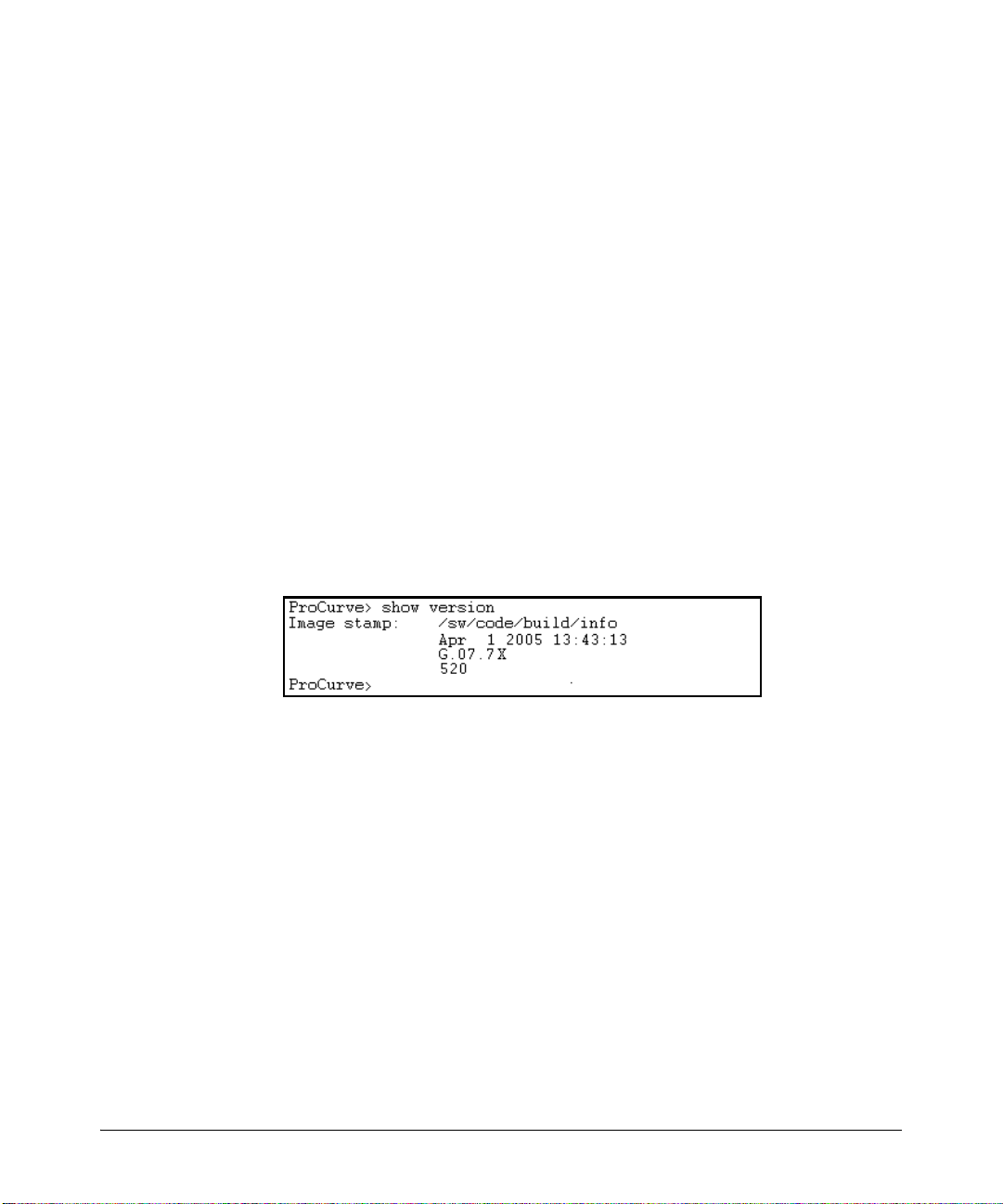
Screen Simulations
Figures containing simulated screen text and command output look like this:
1-6
Figure 1-1. Example of a Figure Showing a Simulated Screen
In some cases, brief command-output sequences appear outside of a
numbered figure. For example:
ProCurve(config)# ip default-gateway 18.28.152.1/24
ProCurve(config)# vlan 1 ip address 18.28.36.152/24
ProCurve(config)# vlan 1 ip igmp
Port Identity Examples
This guide describes software applicable to both chassis-based and stackable
ProCurve switches. Where port identities are needed in an example, this guide
uses the chassis-based port identity system, such as “A1”, “B3 - B5”, “C7”, etc.
However, unless otherwise noted, such examples apply equally to the
stackable switches, which for port identities typically use only numbers, such
as “1”, “3-5”, “15”, etc.
Page 23
Sources for More Information
Getting Started
Sources for More Information
For additional information about switch operation and features not covered
in this guide, consult the following sources:
■ For information on which product manual to consult on a given
software feature, refer to “Product Documentation” on page xi.
Note For the latest version of all ProCurve switch documentation, including
release notes covering recently added features, visit the ProCurve
Networking website at http://www.procurve.com. Click on Technical
support, and then click on Product manuals.
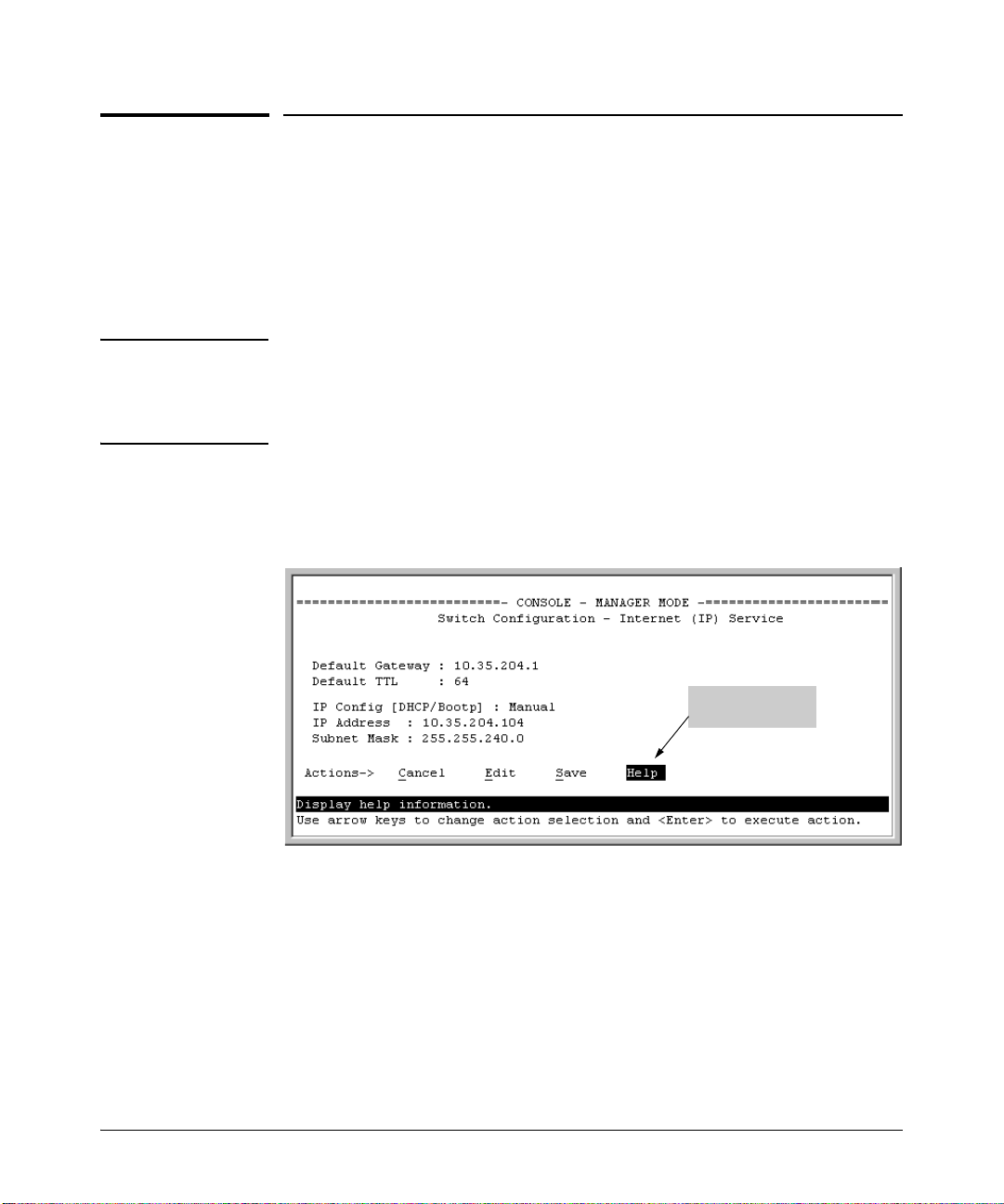
■ For information on specific parameters in the menu interface, refer
to the online help provided in the interface. For example:
Online Help for
Menu interface
Figure 1-2. Getting Help in the Menu Interface
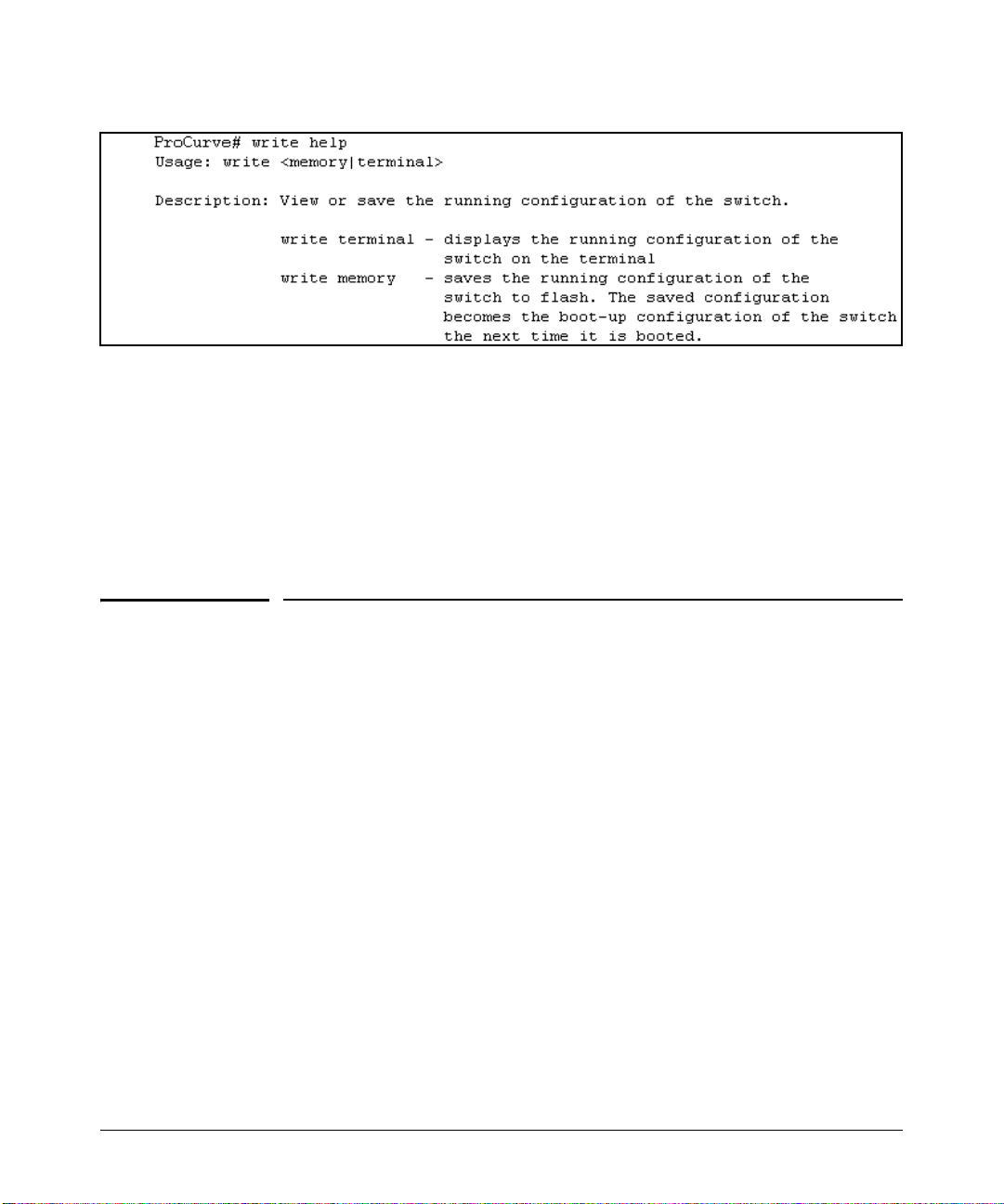
■ For information on a specific command in the CLI, type the command
name followed by “help”. For example:
1-7
Page 24
Getting Started
Need Only a Quick Start?
Figure 1-3. Getting Help in the CLI
■ For information on specific features in the Web browser interface,
use the online help. For more information, refer to the Management
and Configuration Guide for your switch.
■ For further information on ProCurve Networking switch technology,
visit the ProCurve website at:
http://www.procurve.com
1-8
Need Only a Quick Start?
IP Addressing
If you just want to give the switch an IP address so that it can communicate
on your network, or if you are not using multiple VLANs, ProCurve
recommends that you use the Switch Setup screen to quickly configure IP
addressing. To do so, do one of the following:
■ Enter setup at the CLI Manager level prompt.
ProCurve# setup
■ In the Main Menu of the Menu interface, select
8. Run Setup
For more on using the Switch Setup screen, see the Installation and Getting
Started Guide you received with the switch.
Page 25

Need Only a Quick Start?
Getting Started
To Set Up and Install the Switch in Your Network
Important! Use the Installation and Getting Started Guide shipped with your switch for
the following:
■ Notes, cautions, and warnings related to installing and using the
switch and its related modules
■ Instructions for physically installing the switch in your network
■ Quickly assigning an IP address and subnet mask, setting a Manager
password, and (optionally) configuring other basic features.
■ Interpreting LED behavior.
For the latest version of the Installation and Getting Started Guide and other
documentation for your switch, visit the ProCurve website. (Refer to “Product
Documentation” on page xi of this guide for further details.)
1-9
Page 26

Getting Started
Need Only a Quick Start?
— This page is intentionally unused. —
1-10
Page 27

Configuring Username and Password Security
Contents
Overview . . . . . . . . . . . . . . . . . . . . . . . . . . . . . . . . . . . . . . . . . . . . . . . . . . . . . . 2-2
Configuring Local Password Security . . . . . . . . . . . . . . . . . . . . . . . . . . . . . . 2-4
Menu: Setting Passwords . . . . . . . . . . . . . . . . . . . . . . . . . . . . . . . . . . . . . 2-4
CLI: Setting Passwords and Usernames . . . . . . . . . . . . . . . . . . . . . . . . . 2-5
Web: Setting Passwords and Usernames . . . . . . . . . . . . . . . . . . . . . . . . 2-6
Front-Panel Security . . . . . . . . . . . . . . . . . . . . . . . . . . . . . . . . . . . . . . . . . . . . 2-7
When Security Is Important . . . . . . . . . . . . . . . . . . . . . . . . . . . . . . . . . . . 2-7
Front-Panel Button Functions . . . . . . . . . . . . . . . . . . . . . . . . . . . . . . . . . 2-8
Configuring Front-Panel Security . . . . . . . . . . . . . . . . . . . . . . . . . . . . . 2-10
Password Recovery . . . . . . . . . . . . . . . . . . . . . . . . . . . . . . . . . . . . . . . . . 2-15
Password Recovery Process . . . . . . . . . . . . . . . . . . . . . . . . . . . . . . . . . 2-17
2
2-1
Page 28

Configuring Username and Password Security
Overview
Overview
Feature Default Menu CLI Web
Set Usernames none — — page 2-6
Set a Password none page 2-4 page 2-5 page 2-6
Delete Password Protection n/a page 2-4 page 2-6 page 2-6
The following features apply only to the Series 2600, 2600-PWR, and 2800 Switches.
Show front-panel-security n/a — page 1-13 —
Front-panel-security — page 1-13 —
password-clear enabled — page 1-13 —
reset-on-clear disabled — page 1-14 —
factory-reset enabled — page 1-15 —
password-recovery enabled — page 1-15 —
Console access includes both the menu interface and the CLI. There are two
levels of console access: Manager and Operator. For security, you can set a
password pair (username and password) on each of these levels.
Note Usernames are optional. Also, in the menu interface, you can configure
passwords, but not usernames. To configure usernames, use the CLI or the
web browser interface.
Level Actions Permitted
Manager: Access to all console interface areas.
This is the default level. That is, if a Manager password has not been set prior
to starting the current console session, then anyone having access to the
console can access any area of the console interface.
Operator: Access to the Status and Counters menu, the Event Log, and the CLI*, but no
Configuration capabilities.
On the Operator level, the configuration menus, Download OS, and Reboot
Switch options in the Main Menu are not available.
*Allows use of the ping, link-test, show, menu, exit, and logout commands, plus the enable
command if you can provide the Manager password.
2-2
Page 29

Configuring Username and Password Security
Overview
To configure password security:
1. Set a Manager password pair (and an Operator password pair, if applicable
for your system).
2. Exit from the current console session. A Manager password pair will now
be needed for full access to the console.
If you do steps 1 and 2, above, then the next time a console session is started
for either the menu interface or the CLI, a prompt appears for a password.
Assuming you have protected both the Manager and Operator levels, the level
of access to the console interface will be determined by which password is
entered in response to the prompt.
If you set a Manager password, you may also want to configure the
Inactivity Time parameter. (Refer to the Management and Configuration
Guide for your switch.) This causes the console session to end after the
specified period of inactivity, thus giving you added security against unauthorized console access.
Note The manager and operator passwords and (optional) usernames control
access to the menu interface, CLI, and web browser interface.
If you configure only a Manager password (with no Operator password), and
in a later session the Manager password is not entered correctly in response
to a prompt from the switch, then the switch does not allow management
access for that session.
Passwords are case-sensitive.
Caution If the switch has neither a Manager nor an Operator password, anyone
having access to the switch through either Telnet, the serial port, or the web
browser interface can access the switch with full manager privileges. Also,
if you configure only an Operator password, entering the Operator password enables full manager privileges.
The rest of this section covers how to:
■ Set passwords
■ Delete passwords
■ Recover from a lost password
2-3
Page 30
Configuring Username and Password Security
Configuring Local Password Security
Configuring Local Password Security
Menu: Setting Passwords
As noted earlier in this section, usernames are optional. Configuring a username requires either the CLI or the web browser interface.
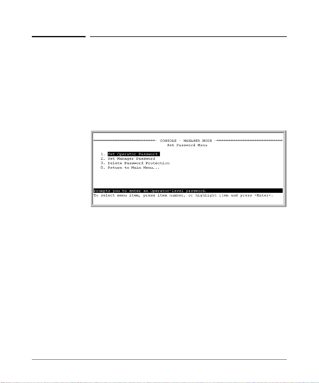
1. From the Main Menu select:
3. Console Passwords
2-4
Figure 2-1. The Set Password Screen
2. To set a new password:
a. Select Set Manager Password or Set Operator Password. You will then
be prompted with Enter new password.
b. Type a password of up to 16 ASCII characters with no spaces and
press
[Enter]. (Remember that passwords are case-sensitive.)
c. When prompted with Enter new password again, retype the new pass-
word and press
After you configure a password, if you subsequently start a new console
session, you will be prompted to enter the password. (If you use the CLI or
web browser interface to configure an optional username, the switch will
prompt you for the username, and then the password.)
To Delete Password Protection (Including Recovery from a Lost
Password): This procedure deletes all usernames (if configured) and pass-
words (Manager and Operator).
[Enter].
Page 31

Configuring Username and Password Security
Configuring Local Password Security
If you have physical access to the switch, press and hold the Clear button (on
the front of the switch) for a minimum of one second to clear all password
protection, then enter new passwords as described earlier in this chapter.
If you do not have physical access to the switch, you will need Manager-Level
access:
1. Enter the console at the Manager level.
2. Go to the Set Passwords screen as described above.
3. Select Delete Password Protection. You will then see the following prompt:
Continue Deletion of password protection? No
4. Press the Space bar to select Ye s, then press
5. Press
[Enter] to clear the Password Protection message.
[Enter].
To Recover from a Lost Manager Password: If you cannot start a console session at the Manager level because of a lost Manager password, you
can clear the password by getting physical access to the switch and pressing
and holding the Clear button for a minimum of one second. This action deletes
all passwords and usernames (Manager and Operator) used by both the
console and the web browser interface.
CLI: Setting Passwords and Usernames
Commands Used in This Section
password See below.
Configuring Manager and Operator Passwords.
Syntax:
[ no ] password <manager | operator > [ user-name ASCII-STR ]
[ no ] password < all >
• Password entries appear
as asterisks.
• You must type the
password entry twice.
Figure 2-2. Example of Configuring Manager and Operator Passwords
2-5
Page 32

Configuring Username and Password Security
Configuring Local Password Security
To Remove Password Protection. Removing password protection means
to eliminate password security. This command prompts you to verify that you
want to remove one or both passwords, then clears the indicated password(s).
(This command also clears the username associated with a password you are
removing.) For example, to remove the Operator password (and username, if
assigned) from the switch, you would do the following:
Press [Y] (for yes) and press [Enter].
Figure 2-3. Removing a Password and Associated Username from the Switch
The effect of executing the command in figure 2-3 is to remove password
protection from the Operator level. (This means that anyone who can access
the switch console can gain Operator access without having to enter a username or password.)
Web: Setting Passwords and Usernames
In the web browser interface you can enter passwords and (optional) usernames.
To Configure (or Remove) Usernames and Passwords in the Web
Browser Interface.
1. Click on the
Click on
[Device Passwords].
Security tab.
2. Do one of the following:
• To set username and password protection, enter the usernames and
passwords you want in the appropriate fields.
• To remove username and password protection, leave the fields blank.
3. Implement the usernames and passwords by clicking on
To access the web-based help provided for the switch, click on
[Apply Changes].
[?] in the web
browser screen.
2-6
Page 33

Configuring Username and Password Security
Front-Panel Security
Front-Panel Security
The front-panel security features provide the ability to independently enable
or disable some of the functions of the two buttons located on the front of the
switch for clearing the password (Clear button) or restoring the switch to its
factory default configuration (Reset+Clear buttons together). The ability to
disable Password Recovery is also provided for situations which require a
higher level of switch security.
The front-panel Security features are designed to prevent malicious users
from:
■ Resetting the password(s) by pressing the Clear button
■ Restoring the factory default configuration by using the Reset+Clear
button combination.
■ Gaining management access to the switch by having physical access to
the switch itself
When Security Is Important
Some customers require a high level of security for information. Also, the
Health Insurance Portability and Accountability Act (HIPAA) of 1996 requires
that systems handling and transmitting confidential medical records must be
secure.
It used to be assumed that only system and network administrators would be
able to get access to a network switch because switches were typically placed
in secure locations under lock and key. For some customers this is no longer
true. Others simply want the added assurance that even if someone did
manage to get to the switch that data would still remain secure.
If you do not invoke front-panel security on the switch, user-defined passwords can be deleted by pushing the Clear button on the front panel. This
function exists so that if customers forget the defined passwords they can still
get back into the switch and reset the passwords. This does, however, leave
the switch vulnerable when it is located in an area where non-authorized
people have access to it. Passwords could easily be cleared by pressing the
Clear button. Someone who has physical access to the switch may be able to
erase the passwords (and possibly configure new passwords) and take control
of the switch.
2-7
Page 34

Configuring Username and Password Security
1
Front-Panel Security
As a result of increased security concerns, customers now have the ability to
stop someone from removing passwords by disabling the Clear and/or Reset
buttons on the front of the switch.
Front-Panel Button Functions
The front panel of the switch includes the Reset button and the Clear button.
Power
Fault
hp procurve
switch
J4899A
Self
Test
Port
LED
View
Fan
Status
Reset
2650
2
1
1
Lnk
Act
FDx
Spd
Spd mode: off = 10 Mbps, flash = 100 Mbps, on = 1000 Mbps
Clear
4
3
6
5
8
7
10
9
12
11
13
Clear ButtonReset Button
Figure 2-4. Example Front-Panel Button Locations
Clear Button
Pressing the Clear button alone for one second resets the password(s) configured on the switch.
Reset Clear
2-8
Figure 2-5. Press the Clear Button for One Second To Reset the Password(s)
Page 35

Configuring Username and Password Security
Front-Panel Security
Reset Button
Pressing the Reset button alone for one second causes the switch to reboot.
Reset Clear
Figure 2-6. Press and hold the Reset Button for One Second To Reboot the Switch
Restoring the Factory Default Configuration
You can also use the Reset button together with the Clear button (Reset+Clear)
to restore the factory default configuration for the switch. To do this:
1. Press and hold the Reset button.
Reset Clear
2. While holding the Reset button, press and hold the Clear button.
Reset Clear
2-9
Page 36

Configuring Username and Password Security
Front-Panel Security
3. Release the Reset button and wait for about one second for the Self-Test
LED to start flashing.
Reset Clear
4. When the Self-Test LED begins flashing, release the Clear button
.
Reset Clear
Self
Te s t
2-10
Self
Te s t
This process restores the switch configuration to the factory default settings.
Configuring Front-Panel Security
Using the front-panel-security command from the global configuration context
in the CLI you can:
• Disable or re-enable the password-clearing function of the Clear
button. Disabling the Clear button means that pressing it does not
remove local password protection from the switch. (This action
affects the Clear button when used alone, but does not affect the
operation of the Reset+Clear combination described under “Restoring the Factory Default Configuration” on page 2-9.)
• Configure the Clear button to reboot the switch after clearing any
local usernames and passwords. This provides an immediate, visual
means (plus an Event Log message) for verifying that any usernames
and passwords in the switch have been cleared.
Page 37

Configuring Username and Password Security
Front-Panel Security
• Modify the operation of the Reset+Clear combination (page 2-9) so
that the switch still reboots, but does not restore the switch’s factory
default configuration settings. (Use of the Reset button alone, to
simply reboot the switch, is not affected.)
• Disable or re-enable Password Recovery.
Syntax: show front-panel-security
Displays the current front-panel-security settings:
Clear Password: Shows the status of the Clear button on the front
panel of the switch. Enabled means that pressing the Clear
button erases the local usernames and passwords configured
on the switch (and thus removes local password protection
from the switch). Disabled means that pressing the Clear
button does not remove the local usernames and passwords
configured on the switch. (Default: Enabled.)
Reset-on-clear: Shows the status of the reset-on-clear option
(Enabled or Disabled). When reset-on-clear is disabled and
Clear Password is enabled, then pressing the Clear button
erases the local usernames and passwords from the switch.
When reset-on-clear is enabled, pressing the Clear button
erases the local usernames and passwords from the switch
and reboots the switch. (Enabling reset-on-clear
automatically enables clear-password.) (Default: Disabled.)
Factory Reset: Shows the status of the Reset button on the front
panel of the switch. Enabled means that pressing the Reset
button reboots the switch and also enables the Reset button to
be used with the Clear button (page 2-9) to reset the switch to
its factory-default configuration. (Default: Enabled.)
Password Recovery: Shows whether the switch is configured
with the ability to recover a lost password. (Refer to
“Password Recovery Process” on page 2-17.) (Default:
Enabled.)
CAUTION: Disabling this option removes the ability to
recover a password on the switch. Disabling this option is
an extreme measure and is not recommended unless you
have the most urgent need for high security. If you disable
password-recovery and then lose the password, you will
have to use the Reset and Clear buttons (page 2-9) to reset
the switch to its factory-default configuration and create a
new password.
2-11
Page 38

Configuring Username and Password Security
Front-Panel Security
For example, show front-panel-security produces the following output when
the switch is configured with the default front-panel security settings.
Figure 2-7. The Default Front-Panel Security Settings
Disabling the Clear Password Function of the Clear Button on the Switch’s Front Panel
Syntax: no front-panel-security password-clear
In the factory-default configuration, pressing the Clear button
on the switch’s front panel erases any local usernames and
passwords configured on the switch. This command disables
the password clear function of the Clear button, so that
pressing it has no effect on any local usernames and
passwords. (Default: Enabled.)
Note: Although the Clear button does not erase passwords
when disabled, you can still use it with the Reset button
(Reset+Clear) to restore the switch to its factory default
configuration, as described under “Restoring the Factory
Default Configuration” on page 2-9 .
This command displays a Caution message in the CLI. If you want to proceed
with disabling the Clear button, type
[Y]; otherwise type [N]. For example:
Indicates the command has disabled the Clear
button on the switch’s front panel. In this case
the Show command does not include the reset-
on-clear status because it is inoperable while
the Clear Password functionality is disabled, and
must be reconfigured whenever Clear Password
is re-enabled .
Figure 2-8. Example of Disabling the Clear Button and Displaying the New Configuration
2-12
Page 39

Configuring Username and Password Security
Front-Panel Security
Re-Enabling the Clear Button on the Switch’s Front Panel and Setting or Changing the “Reset-On-Clear” Operation
Syntax: [no] front-panel-security password-clear reset-on-clear
This command does both of the following:
• Re-enables the password-clearing function of the Clear
button on the switch’s front panel.
• Specifies whether the switch reboots if the Clear button is
pressed.
To re-enable password-clear, you must also specify whether to
enable or disable the reset-on-clear option.
Defaults:
– password-clear: Enabled.
– reset-on-clear: Disabled.
Thus:
• To enable password-clear with reset-on-clear disabled, use
this syntax:
no front-panel-security password-clear reset-on-clear
• To enable password-clear with reset-on-clear also enabled,
use this syntax:
front-panel-security password-clear reset-on-clear
(Either form of the command enables
password-clear.)
Note: If you disable password-clear and also disable the
password-recovery option, you can still recover from a lost
password by using the Reset+Clear button combination at
reboot as described on page 2-9. Although the Clear button
does not erase passwords when disabled, you can still use
it with the Reset button (Reset+Clear) to restore the switch
to its factory default configuration. You can then get access
to the switch to set a new password.
For example, suppose that password-clear is disabled and you want to restore
it to its default configuration (enabled, with reset-on-clear disabled).
2-13
Page 40

Configuring Username and Password Security
Front-Panel Security
Figure 2-9. Example of Re-Enabling the Clear Button’s Default Operation
Changing the Operation of the Reset+Clear Combination
In their default configuration, using the Reset+Clear buttons in the combination described under “Restoring the Factory Default Configuration” on page
2-9 replaces the switch’s current startup-config file with the factory-default
startup-config file, then reboots the switch, and removes local password
protection. This means that anyone who has physical access to the switch
could use this button combination to replace the switch’s current configuration with the factory-default configuration, and render the switch accessible without the need to input a username or password. You can use the
factory-reset command to prevent the Reset+Clear combination from being
used for this purpose.
Shows password-clear disabled.
Enables password-clear, with reset-on-
clear disabled by the “no” statement at
the beginning of the command.
Shows password-clear enabled, with
reset-on-clear disabled.
2-14
Syntax: [no] front-panel-security factory-reset
Disables or re-enables the following functions associated with
using the Reset+Clear buttons in the combination described
under “Restoring the Factory Default Configuration” on page 2-9:
• Replacing the current startup-config file with the factorydefault startup-config file
• Clearing any local usernames and passwords configured on
the switch
(Default: Both functions enabled.)
Notes: The Reset+Clear button combination always reboots
the switch, regardless of whether the “no” form of the
command has been used to disable the above two functions.
Also, if you disable factory-reset, you cannot disable the
password-recovery option, and the reverse.
Page 41

The command to disable the factory-reset operation produces this caution.
To complete the command, press [Y]. To abort the command, press [N].
Figure 2-10. Example of Disabling the Factory Reset Option
Password Recovery
The password recovery feature is enabled by default and provides a method
for regaining management access to the switch (without resetting the switch
to its factory default configuration) in the event that the system administrator
loses the local manager username (if configured) or password. Using Password Recovery requires:
■ password-recovery enabled (the default) on the switch prior to an attempt
to recover from a lost username/password situation
■ Contacting your ProCurve Customer Care Center to acquire a one-time-
use password
Configuring Username and Password Security
Front-Panel Security
Completes the command to
disable the factory reset option.
Displays the current frontpanel-security configuration,
with Factory Reset disabled.
Disabling or Re-Enabling the Password Recovery Process
Disabling the password recovery process means that the only method for
recovering from a lost manager username (if configured) and password is to
reset the switch to its factory-default configuration, which removes any non
default configuration settings.
Caution Disabling password-recovery requires that factory-reset be enabled, and locks
out the ability to recover a lost manager username (if configured) and password on the switch. In this event, there is no way to recover from a lost
manager username/password situation without resetting the switch to its
factory-default configuration. This can disrupt network operation and make
it necessary to temporarily disconnect the switch from the network to prevent
unauthorized access and other problems while it is being reconfigured. Also,
with factory-reset enabled, unauthorized users can use the Reset+Clear button
combination to reset the switch to factory-default configuration and gain
management access to the switch.
2-15
Page 42

Configuring Username and Password Security
Front-Panel Security
Syntax: [no] front-panel-security password-recovery
Enables or (using the “no” form of the command) disables the
ability to recover a lost password.
When this feature is enabled, the switch allows management
access through the password recovery process described below.
This provides a method for recovering from a lost manager
username (if configured) and password. When this feature is
disabled, the password recovery process is disabled and the
only way to regain management access to the switch is to use
the Reset+Clear button combination (page 2-9) to restore the
switch to its factory default configuration.
(Default: Enabled.)
Steps for Disabling Password-Recovery.
1. Set the CLI to the global interface context.
Note: To disable password-recovery:
– You must have physical access to the front panel of th e switch.
– The factory-reset parameter must be enabled (the default).
2. Use show front-panel-security to determine whether the factory-reset
parameter is enabled. If it is disabled, use the front-panel-security factory-
reset command to enable it.
3. Press and release the Clear button on the front panel of the switch.
4. Within 60-seconds of pressing the Clear button, enter the following command:
no front-panel-security password-recovery
5. Do one of the following after the “CAUTION” message appears:
• If you want to complete the command, press
• If you want to abort the command, press
[Y] (for “Yes”).
[N] (for “No”)
Figure 2-11 shows an example of disabling the password-recovery parameter.
2-16
Page 43

Configuring Username and Password Security
Figure 2-11. Example of the Steps for Disabling Password-Recovery
Front-Panel Security
Password Recovery Process
If you have lost the switch’s manager username/password, but password-
recovery is enabled, then you can use the Password Recovery Process to gain
management access to the switch with an alternate password supplied by
ProCurve.
Note If you have disabled password-recovery, which locks out the ability to recover a
manager username/password pair on the switch, then the only way to recover
from a lost manager username/password pair is to use the Reset+Clear button
combination described under “Restoring the Factory Default Configuration”
on page 2-9. This can disrupt network operation and make it necessary to
temporarily disconnect the switch from the network to prevent unauthorized
access and other problems while it is being reconfigured.
To use the password-recovery option to recover a lost password:
1. Note the switch’s base MAC address. It is shown on the label located on
the upper right front corner of the switch.
2. Contact your ProCurve Customer Care Center for further assistance.
Using the switch’s MAC address, the ProCurve Customer Care Center will
generate and provide a “one-time use” alternate password you can use
with the to gain management access to the switch. Once you gain access,
you can configure a new, known password.
Note The alternate password provided by the ProCurve Customer Care Center is
valid only for a single login attempt.
You cannot use the same “one-time-use” password if you lose the password
a second time. Because the password algorithm is randomized based upon
your switch's MAC address, the password will change as soon as you use the
“one-time-use” password provided to you by the ProCurve Customer Care
Center.
2-17
Page 44

Configuring Username and Password Security
Front-Panel Security
— This page is intentionally unused. —
2-18
Page 45

Web and MAC Authentication for the Series 2600/2600-PWR and 2800 Switches
Contents
Overview . . . . . . . . . . . . . . . . . . . . . . . . . . . . . . . . . . . . . . . . . . . . . . . . . . . . . . 3-2
Client Options . . . . . . . . . . . . . . . . . . . . . . . . . . . . . . . . . . . . . . . . . . . . . . 3-3
General Features . . . . . . . . . . . . . . . . . . . . . . . . . . . . . . . . . . . . . . . . . . . . 3-4
How Web and MAC Authentication Operate . . . . . . . . . . . . . . . . . . . . . . . . 3-5
Authenticator Operation . . . . . . . . . . . . . . . . . . . . . . . . . . . . . . . . . . . . . 3-5
Terminology . . . . . . . . . . . . . . . . . . . . . . . . . . . . . . . . . . . . . . . . . . . . . . . . . . . 3-9
Operating Rules and Notes . . . . . . . . . . . . . . . . . . . . . . . . . . . . . . . . . . . . . . 3-10
General Setup Procedure for Web/MAC Authentication . . . . . . . . . . . . . . 3-12
Do These Steps Before You Configure Web/MAC Authentication . . 3-12
Additional Information for Configuring the RADIUS Server
To Support MAC Authentication . . . . . . . . . . . . . . . . . . . . . . . . . . . . . . 3-14
3
Configuring the Switch To Access a RADIUS Server . . . . . . . . . . . . . . . . 3-15
Configuring Web Authentication . . . . . . . . . . . . . . . . . . . . . . . . . . . . . . . . . 3-17
Overview . . . . . . . . . . . . . . . . . . . . . . . . . . . . . . . . . . . . . . . . . . . . . . . . . . 3-17
Configure the Switch for Web-Based Authentication . . . . . . . . . . . . . 3-18
Configuring MAC Authentication on the Switch . . . . . . . . . . . . . . . . . . . . 3-22
Overview . . . . . . . . . . . . . . . . . . . . . . . . . . . . . . . . . . . . . . . . . . . . . . . . . . 3-22
Configure the Switch for MAC-Based Authentication . . . . . . . . . . . . 3-23
Show Status and Configuration of Web-Based Authentication . . . . . . . . 3-26
Show Status and Configuration of MAC-Based Authentication . . . . . . . . 3-27
Show Client Status . . . . . . . . . . . . . . . . . . . . . . . . . . . . . . . . . . . . . . . . . . . . . 3-29
3-1
Page 46

Web and MAC Authentication for the Series 2600/2600-PWR and 2800 Switches
Overview
Overview
Feature Default Menu CLI Web
Configure Web Authentication n/a — 3-17 —
Configure MAC Authentication n/a — 3-22 —
Display Web Authentication Status and Configuration n/a — 3-26 —
Display MAC Authentication Status and Configuration n/a — 3-27 —
Applicable Switch Models. Web and MAC Authentication are available on
these current ProCurve switch models:
■ ProCurve Series 2600 and 2600-PWR Switches
■ ProCurve Series 2800 Switches
Web and MAC Authentication are designed for employment on the “edge” of
a network to provide port-based security measures for protecting private
networks and the switch itself from unauthorized access. Because neither
method requires clients to run any special supplicant software, both are
suitable for legacy systems and temporary access situations where introducing supplicant software is not an attractive option. Both methods rely on using
a RADIUS server for authentication. This simplifies access security management by allowing you to control access from a master database in a single
server. (You can use up to three RADIUS servers to provide backups in case
access to the primary server fails.) It also means the same credentials can be
used for authentication, regardless of which switch or switch port is the
current access point into the LAN.
Web Authentication (Web-Auth). This method uses a web page login to
authenticate users for access to the network. When a user connects to the
switch and opens a web browser the switch automatically presents a login
page. The user then enters a username and password, which the switch
forwards to a RADIUS server for authentication. After authentication, the
switch grants access to the secured network. Other than a web browser, the
client needs no special supplicant software.
Note Client web browsers may not use a proxy server to access the network.
3-2
Page 47

Web and MAC Authentication for the Series 2600/2600-PWR and 2800 Switches
MAC Authentication (MAC-Auth). This method grants access to a secure
network by authenticating devices for access to the network. When a device
connects to the switch, either by direct link or through the network, the switch
forwards the device’s MAC address to the RADIUS server for authentication.
The RADIUS server uses the device MAC address as the username and
password, and grants or denies network access in the same way that it does
for clients capable of interactive logons. (The process does not use either a
client device configuration or a logon session.) MAC authentication is wellsuited for clients that are not capable of providing interactive logons, such as
telephones, printers, and wireless access points. Also, because most RADIUS
servers allow for authentication to depend on the source switch and port
through which the client connects to the network, you can use MAC-Auth to
“lock” a particular device to a specific switch and port.
Overview
Note You can configure only one authentication type on a port. This means that Web
authentication, MAC authentication, 802.1X, MAC lockdown, MAC lockout,
and port-security are mutually exclusive on a given port. Also, LACP must be
disabled on ports configured for any of these authentication methods.
Client Options
Web-Auth and MAC-Auth provide a port-based solution in which a port can
belong to one, untagged VLAN at a time. However, where all clients can
operate in the same VLAN, the switch allows up to 32 simultaneous clients per
port. (In applications where you want the switch to simultaneously support
multiple client sessions in different VLANs, design your system so that such
clients will use different switch ports.)
In the default configuration, the switch blocks access to clients that the
RADIUS server does not authenticate. However, you can configure an individual port to provide limited services to unauthorized clients by joining a
specified “unauthorized” VLAN during sessions with such clients. The unauthorized VLAN assignment can be the same for all ports, or different, depending on the services and access you plan to allow for unauthenticated clients.
Access to an optional, unauthorized VID is configured in the switch when Web
and MAC Authentication are configured on a port.
3-3
Page 48

Web and MAC Authentication for the Series 2600/2600-PWR and 2800 Switches
Overview
General Features
Web and MAC Authentication on the ProCurve Series 2600, 2600-PWR, and
2800 switches include the following:
■ On a port configured for Web or MAC Authentication, the switch
operates as a port-access authenticator using a RADIUS server and
the CHAP protocol. Inbound traffic is processed by the switch alone,
until authentication occurs. Some traffic from the switch is available
to an unauthorized client (for example, broadcast or unknown destination packets) before authentication occurs.
■ Proxy servers may not be used by browsers accessing the switch
through ports using Web Authentication.
■ You can optionally configure the switch to temporarily assign “autho-
rized” and “unauthorized” VLAN memberships on a per-port basis to
provide different services and access to authenticated and unauthenticated clients.
■ Web pages for username and password entry and the display of
authorization status are provided when using Web Authentication.
■ You can use the RADIUS server to temporarily assign a port to a static
VLAN to support an authenticated client. When a RADIUS server
authenticates a client, the switch-port membership during the client’s
connection is determined according to the following hierarchy:
1. A RADIUS-assigned VLAN
2. An authorized VLAN specified in the Web- or MAC-Auth configuration
for the subject port.
3. A static, port-based, untagged VLAN to which the port is configured.
A RADIUS-assigned VLAN has priority over switch-port membership
in any VLAN.
3-4
■ You can allow wireless clients to move between switch ports under
Web/MAC Authentication control. Clients may move from one Web
authorized port to another or from one MAC authorized port to
another. This capability allows wireless clients to move from one
access point to another without having to reauthenticate.
■ Unlike 802.1X operation, clients do not need supplicant software for
Web or MAC Authentication; only a web browser (for Web Authentication) or a MAC address (for MAC Authentication).
■ You can use “Show” commands to display session status and port-
access configuration settings.
Page 49

Web and MAC Authentication for the Series 2600/2600-PWR and 2800 Switches
How Web and MAC Authentication Operate
How Web and MAC Authentication
Operate
Authenticator Operation
Before gaining access to the network clients first present their authentication
credentials to the switch. The switch then verifies the supplied credentials
with a RADIUS authentication server. Successfully authenticated clients
receive access to the network, as defined by the System Administrator. Clients
who fail to authenticate successfully receive no network access or limited
network access as defined by the System Administrator.
Web-based Authentication
When a client connects to a Web-Auth enabled port communication is redirected to the switch. A temporary IP address is assigned by the switch and a
login screen is presented for the client to enter their credentials.
Figure 3-1. Example of User Login Screen
The temporary IP address pool can be specified using the dhcp-addr and
dhcp-lease options of the aaa port-access web-based command. If SSL is
enabled on the switch and ssl-login is enabled on the port the client is
redirected to a secure login page (https://...).
The switch passes the supplied username and password to the RADIUS server
for authentication.
3-5
Page 50

Web and MAC Authentication for the Series 2600/2600-PWR and 2800 Switches
How Web and MAC Authentication Operate
Figure 3-2. Progress Message During Authentication
If the client is authenticated and the maximum number of clients allowed on
the port (client-limit) has not been reached, the port is assigned to a static,
untagged VLAN for network access. If specified, the client is redirected to a
specific URL (redirect-url).
Figure 3-3. Authentication Completed
3-6
The assigned VLAN is determined, in order of priority, as follows:
1. If there is a RADIUS-assigned VLAN, then, for the duration of the client
session, the port belongs to this VLAN and temporarily drops all other
VLAN memberships.
2. If there is no RADIUS-assigned VLAN, then, for the duration of the client
session, the port belongs to the authorized VLAN (auth-vid if configured)
and temporarily drops all other VLAN memberships.
3. If neither 1 or 2, above, apply, but the port is an untagged member of a
statically configured, port-based VLAN, then the port remains in this
VLAN.
4. If neither 1, 2, or 3, above, apply, then the client session does not have
access to any statically configured, untagged VLANs and client access is
blocked.
The assigned port VLAN remains in place until the session ends. Clients may
be forced to reauthenticate after a fixed period of time (reauth-period) or at
any time during a session (reauthenticate). An implicit logoff period can be set
if there is no activity from the client after a given amount of time (logoff-period).
In addition, a session ends if the link on the port is lost, requiring reauthentication of all clients. Also, if a client moves from one port to another and client
Page 51

Web and MAC Authentication for the Series 2600/2600-PWR and 2800 Switches
moves have not been enabled (client-moves) on the ports, the session ends and
the client must reauthenticate for network access. At the end of the session
the port returns to its pre-authentication state. Any changes to the port’s VLAN
memberships made while it is an authorized port take affect at the end of the
session.
A client may not be authenticated due to invalid credentials or a RADIUS
server timeout. The max-retries parameter specifies how many times a client
may enter their credentials before authentication fails. The server-timeout
parameter sets how long the switch waits to receive a response from the
RADIUS server before timing out. The max-requests parameter specifies how
many authentication attempts may result in a RADIUS server timeout before
authentication fails. The switch waits a specified amount of time (quiet-
period) before processing any new authentication requests from the client.
Network administrators may assign unauthenticated clients to a specific
static, untagged VLAN (unauth-vid), to provide access to specific (guest)
network resources. If no VLAN is assigned to unauthenticated clients the port
is blocked and no network access is available. Should another client successfully authenticate through that port any unauthenticated clients on the unauth-
vid are dropped from the port.
How Web and MAC Authentication Operate
MAC-based Authentication
When a client connects to a MAC-Auth enabled port traffic is blocked. The
switch immediately submits the client’s MAC address (in the format specified
by the addr-format) as its certification credentials to the RADIUS server for
authentication.
If the client is authenticated and the maximum number of MAC addresses
allowed on the port (addr-limit) has not been reached, the port is assigned to
a static, untagged VLAN for network access.
The assigned VLAN is determined, in order of priority, as follows:
1. If there is a RADIUS-assigned VLAN, then, for the duration of the client
session, the port belongs to this VLAN and temporarily drops all other
VLAN memberships.
2. If there is no RADIUS-assigned VLAN, then, for the duration of the client
session, the port belongs to the Authorized VLAN (auth-vid if configured)
and temporarily drops all other VLAN memberships.
3. If neither 1 or 2, above, apply, but the port is an untagged member of a
statically configured, port-based VLAN, then the port remains in this
VLAN.
3-7
Page 52

Web and MAC Authentication for the Series 2600/2600-PWR and 2800 Switches
How Web and MAC Authentication Operate
4. If neither 1, 2, or 3, above, apply, then the client session does not have
access to any statically configured, untagged VLANs and client access is
blocked.
The assigned port VLAN remains in place until the session ends. Clients may
be forced to reauthenticate after a fixed period of time (reauth-period) or at
any time during a session (reauthenticate). An implicit logoff period can be set
if there is no activity from the client after a given amount of time (logoff-period).
In addition, a session ends if the link on the port is lost, requiring reauthentication of all clients. Also, if a client moves from one port to another and client
moves have not been enabled (addr-moves) on the ports, the session ends and
the client must reauthenticate for network access. At the end of the session
the port returns to its pre-authentication state. Any changes to the port’s VLAN
memberships made while it is an authenticated port take affect at the end of
the session.
A client may not be authenticated due to invalid credentials or a RADIUS
server timeout. The server-timeout parameter sets how long the switch waits
to receive a response from the RADIUS server before timing out. The max-
requests parameter specifies how many authentication attempts may result in
a RADIUS server timeout before authentication fails. The switch waits a
specified amount of time (quiet-period) before processing any new authentication requests from the client.
3-8
Network administrators may assign unauthenticated clients to a specific
static, untagged VLAN (unauth-vid), to provide access to specific (guest)
network resources. If no VLAN is assigned to unauthenticated clients the port
remains in its original VLAN configuration. Should another client successfully
authenticate through that port any unauthenticated clients are dropped from
the port.
Page 53

Web and MAC Authentication for the Series 2600/2600-PWR and 2800 Switches
Terminology
Terminology
Authorized-Client VLAN: Like the Unauthorized-Client VLAN, this is a
conventional, static, untagged, port-based VLAN previously configured on
the switch by the System Administrator. The intent in using this VLAN is
to provide authenticated clients with network access and services. When
the client connection terminates, the port drops its membership in this
VLAN.
Authentication Server: The entity providing an authentication service to
the switch, for example, a RADIUS server.
Authenticator: In ProCurve switch applications, a device that requires a
client or device to provide the proper credentials (MAC address, or
username and password) before being allowed access to the network.
CHAP: Challenge Handshake Authentication Protocol. Also known as
“CHAP-RADIUS”.
Client: In this application, an end-node device such as a management station,
workstation, or mobile PC linked to the switch through a point-to-point
LAN link.
Redirect URL: A System Administrator-specified web page presented to an
authorized client following Web Authentication. ProCurve recommends
specifying this URL when configuring Web Authentication on a switch.
Refer to aaa port-access web-based [e] < port-list > [redirect-url < url >] on
page 3-21.
Static VLAN: A VLAN that has been configured as “permanent” on the switch
by using the CLI vlan < vid > command or the Menu interface.
Unauthorized-Client VLAN: A conventional, static, untagged, port-based
VLAN previously configured on the switch by the System Administrator.
It is used to provide limited network access and services to clients who
are not authenticated.
3-9
Page 54

Web and MAC Authentication for the Series 2600/2600-PWR and 2800 Switches
Operating Rules and Notes
Operating Rules and Notes
■ You can configure one type of authentication on a port. That is, the
following authentication types are mutually exclusive on a given
port:
• Web Authentication
• MAC Authentication
• 802.1X
■ Order of Precedence for Port Access Management (highest to lowest):
• MAC lockout
• MAC lockdown or Port Security
• Port-based Access Control (802.1X) or Web Authentication or MAC
Authentication
Note on Port
Access
Management
When configuring a port for Web or MAC Authentication, be sure that a higher
precedent port access management feature is not enabled on the port. For
example, be sure that Port Security is disabled on a port before configuring it
for Web or MAC Authentication. If Port Security is enabled on the port this
misconfiguration does not allow Web or MAC Authentication to occur.
■ VLANs: If your LAN does not use multiple VLANs, then you do not
need to configure VLAN assignments in your RADIUS server or
consider using either Authorized or U na u th o ri z ed V LA N s. If y ou r LA N
does use multiple VLANs, then some of the following factors may
apply to your use of Web-Auth and MAC-Auth.
• Web-Auth and MAC-Auth operate only with port-based VLANs. Oper-
ation with protocol VLANs is not supported, and clients do not have
access to protocol VLANs during Web-Auth and MAC-Auth sessions.
• A port can belong to one, untagged VLAN during any client session.
Where multiple authenticated clients may simultaneously use the
same port, they must all be capable of operating on the same VLAN.
• During an authenticated client session, the following hierarchy deter-
mines a port’s VLAN membership:
1. If there is a RADIUS-assigned VLAN, then, for the duration of the
client session, the port belongs to this VLAN and temporarily
drops all other VLAN memberships.
3-10
Page 55

Web and MAC Authentication for the Series 2600/2600-PWR and 2800 Switches
Operating Rules and Notes
2. If there is no RADIUS-assigned VLAN, then, for the duration of
the client session, the port belongs to the Authorized VLAN (if
configured) and temporarily drops all other VLAN memberships.
3. If neither 1 or 2, above, apply, but the port is an untagged member
of a statically configured, port-based VLAN, then the port remains
in this VLAN.
4. If neither 1, 2, or 3, above, apply, then the client session does not
have access to any statically configured, untagged VLANs and
client access is blocked.
• After an authorized client session begins on a given port, the port’s
VLAN membership does not change. If other clients on the same port
become authenticated with a different VLAN assignment than the first
client, the port blocks access to these other clients until the first client
session ends.
• The optional “authorized” VLAN (auth-vid) and “unauthorized” VLAN
(unauth-vid) you can configure for Web- or MAC-based authentication
must be statically configured VLANs on the switch. Also, if you
configure one or both of these options, any services you want clients
in either category to access must be available on those VLANs.
■ Where a given port’s configuration includes an unauthorized client
VLAN assignment, the port will allow an unauthenticated client
session only while there are no requests for an authenticated client
session on that port. In this case, if there is a successful request for
authentication from an authorized client, the switch terminates the
unauthorized-client session and begins the authorized-client session.
■ When a port on the switch is configured for Web or MAC Authentica-
tion and is supporting a current session with another device,
rebooting the switch invokes a re-authentication of the connection.
■ When a port on the switch is configured as a Web- or MAC-based
authenticator, it blocks access to a client that does not provide the
proper authentication credentials. If the port configuration includes
an optional, unauthorized VLAN (unauth-vid), the port is temporarily
placed in the unauthorized VLAN if there are no other authorized
clients currently using the port with a different VLAN assignment. If
an authorized client is using the port with a different VLAN or if there
is no unauthorized VLAN configured, the unauthorized client does not
receive access to the network.
■ Web- or MAC-based authentication and LACP cannot both be enabled
on the same port.
3-11
Page 56

Web and MAC Authentication for the Series 2600/2600-PWR and 2800 Switches
General Setup Procedure for Web/MAC Authentication
Note on Web/
MAC
Authentication
The switch does not allow Web or MAC Authentication and LACP to both be
enabled at the same time on the same port. The switch automatically disables
LACP on ports configured for Web or MAC Authentication.
and LACP
General Setup Procedure for Web/MAC
Authentication
Note Web and MAC Authentication are available on these current ProCurve switch
models:
■ ProCurve Series 2600 and 2600-PWR Switches
■ ProCurve Series 2800 Switches
Do These Steps Before You Configure Web/MAC Authentication
3-12
1. Configure a local username and password on the switch for both the
Operator (login) and Manager (enable) access levels. (While this is not
required for a Web- or MAC-based configuration, ProCurve recommends
that you use a local user name and password pair, at least until your other
security measures are in place, to protect the switch configuration from
unauthorized access.)
2. Determine which ports on the switch you want to operate as authenticators. Note that before you configure Web- or MAC-based authentication
on a port operating in an LACP trunk, you must remove the port from the
trunk. (refer to the “Note on Web/MAC Authentication and LACP” on
page 3-12.)
3. Determine whether any VLAN assignments are needed for authenticated
clients.
Page 57

Web and MAC Authentication for the Series 2600/2600-PWR and 2800 Switches
General Setup Procedure for Web/MAC Authentication
a. If you configure the RADIUS server to assign a VLAN for an authen-
ticated client, this assignment overrides any VLAN assignments configured on the switch while the authenticated client session remains
active. Note that the VLAN must be statically configured on the
switch.
b. If there is no RADIUS-assigned VLAN, the port can join an “Authorized
VLAN” for the duration of the client session, if you choose to configure
one. This must be a port-based, statically configured VLAN on the
switch.
c. If there is neither a RADIUS-assigned VLAN or an “Authorized VLAN”
for an authenticated client session on a port, then the port’s VLAN
membership remains unchanged during authenticated client sessions. In this case, configure the port for the VLAN in which you want
it to operate during client sessions.
Note that when configuring a RADIUS server to assign a VLAN, you can
use either the VLAN’s name or VID. For example, if a VLAN configured in
the switch has a VID of 100 and is named vlan100, you could configure the
RADIUS server to use either “100” or “vlan100” to specify the VLAN.
4. Determine whether to use the optional “Unauthorized VLAN” mode for
clients that the RADIUS server does not authenticate. This VLAN must be
statically configured on the switch. If you do not configure an “Unauthorized VLAN”, the switch simply blocks access to unauthenticated clients
trying to use the port.
5. Determine the authentication policy you want on the RADIUS server and
configure the server. Refer to the documentation provided with your
RADIUS application and include the following in the policy for each client
or client device:
• The CHAP-RADIUS authentication method.
• An encryption key
• One of the following:
– If you are configuring Web-based authentication, include the user
name and password for each authorized client.
– If you are configuring MAC-based authentication, enter the
device MAC address in both the username and password fields of
the RADIUS policy configuration for that device. Also, if you want
to allow a particular device to receive authentication only
through a designated port and switch, include this in your policy.
6. Determine the IP address of the RADIUS server(s) you will use to support
Web- or MAC-based authentication. (For information on configuring the
switch to access RADIUS servers, refer to “Configuring the Switch To
Access a RADIUS Server” on page 3-15.)
3-13
Page 58

Web and MAC Authentication for the Series 2600/2600-PWR and 2800 Switches
General Setup Procedure for Web/MAC Authentication
Additional Information for Configuring the RADIUS Server To Support MAC Authentication
On the RADIUS server, configure the client device authentication in the same
way that you would any other client, except:
■ Configure the client device’s (hexadecimal) MAC address as both
username and password. Be careful to configure the switch to use the
same format that the RADIUS server uses. Otherwise, the server will
deny access. The switch provides four format options:
aabbccddeeff (the default format)
aabbcc-ddeeff
aa-bb-cc-dd-ee-ff
aa:bb:cc:dd:ee:ff
Note on MAC
Addresses
Letters in MAC addresses must be in lowercase.
■ If the device is a switch or other VLAN-capable device, use the base
MAC address assigned to the device, and not the MAC address
assigned to the VLAN through which the device communicates with
the authenticator switch. Note that each switch covered by this guide
applies a single MAC address to all VLANs configured in the switch.
Thus, for a given switch, the MAC address is the same for all VLANs
configured on the switch. (Refer to the chapter titled “Static Virtual
LANs (VLANs)” in the Advanced Traffic Management Guide for your
switch.)
3-14
Page 59

Web and MAC Authentication for the Series 2600/2600-PWR and 2800 Switches
Configuring the Switch To Access a RADIUS Server
Configuring the Switch To Access a
RADIUS Server
RADIUS Server Configuration Commands
radius-server
ip-address>] below
[host <
[key < global-key-string
radius-server host <
This section describes the minimal commands for configuring a RADIUS
server to support Web-Auth and MAC Auth. For information on other RADIUS
command options, refer to chapter 5, “RADIUS Authentication and Accounting” .
Syntax: [no] radius-server
[host < ip-address >]
[key < global-key-string >]
Syntax: radius-server host < ip-address > key <server-specific key-string>
[no] radius-server host < ip-address > key
>] below
ip-address> key <server-specific key-string>3-15
Adds a server to the RADIUS configuration or (with no)
deletes a server from the configuration. You can configure up to three RADIUS server addresses. The switch uses
the first server it successfully accesses. (Refer to
“RADIUS Authentication and Accounting” on page 5-1.)
Specifies the global encryption key the switch uses with
servers for which the switch does not have a serverspecific key assignment (below). This key is optional if
all RADIUS server addresses configured in the switch
include a server-specific encryption key. (Default: Null.)
3-15
Page 60

Web and MAC Authentication for the Series 2600/2600-PWR and 2800 Switches
Configuring the Switch To Access a RADIUS Server
Optional. Specifies an encryption key for use during
authentication (or accounting) sessions with the specified server. This key must match the encryption key used
on the RADIUS server. Use this command only if the
specified server requires a different encryption key than
configured for the global encryption key, above.
The no form of the command removes the key configured
for a specific server.
For example, to configure the switch to access a RADIUS server at IP address
192.168.32.11 using a server-specific shared secret key of ‘2Pzo22’
ProCurve(config)# radius-server host 192.168.32.11 key 2Pzo22
ProCurve(config)# show radius
Status and Counters - General RADIUS Information
Deadtime(min) : 0
Timeout(secs) : 5
Retransmit Attempts : 3
Global Encryption Key :
Auth Acct
Server IP Addr Port Port Encryption Key
--------------- ----- ----- --------------------------------
192.168.32.11 1812 1813 2Pzo22
ProCurve(config)#
3-16
Figure 3-4. Example of Configuring a Switch To Access a RADIUS Server
Page 61

Web and MAC Authentication for the Series 2600/2600-PWR and 2800 Switches
Configuring Web Authentication
Configuring Web Authentication
This feature is available only on the Series 2600, 2600-PWR, and 2800
switches.
Overview
1. If you have not already done so, configure a local username and password
pair on the switch.
2. Identify or create a redirect URL for use by authenticated clients. ProCurve recommends that you provide a redirect URL when using Web
Authentication. If a redirect URL is not specified, web browser behavior
following authentication may not be acceptable.
3. If you plan to use multiple VLANs with Web Authentication, ensure that
these VLANs are configured on the switch and that the appropriate port
assignments have been made. Also, confirm that the VLAN used by
authorized clients can access the redirect URL.
4. Use the ping command in the switch console interface to ensure that the
switch can communicate with the RADIUS server you have configured to
support Web-Auth on the switch.
5. Configure the switch with the correct IP address and encryption key to
access the RADIUS server.
6. Configure the switch for Web-Auth:
a. Configure Web Authentication on the switch ports you want to use.
b. If the necessary to avoid address conflicts with the secure network,
specify the base IP address and mask to be used by the switch for
temporary DHCP addresses.The lease length for these temporary IP
addresses may also be set.
c. If you plan to use SSL for logins configure and enable SSL on the
switch before you specify it for use with Web-Auth.
d. Configure the switch to use the redirect URL for authorized clients.
7. Test both authorized and unauthorized access to your system to ensure
that Web Authentication works properly on the ports you have configured
for port-access using Web Authentication.
Note Client web browsers may not use a proxy server to access the network.
3-17
Page 62

Web and MAC Authentication for the Series 2600/2600-PWR and 2800 Switches
Configuring Web Authentication
Configure the Switch for Web-Based Authentication
Command Page
Configuration Level
aaa port-access web-based dhcp-addr 3-18
aaa port-access web-based dhcp-lease 3-18
[no] aaa port-access web-based [e] < port-list > 3-19
[auth-vid] 3-19
[client-limit] 3-19
[client-moves] 3-19
[logoff-period] 3-20
[max-requests] 3-20
[max-retries] 3-20
[quiet-period] 3-20
[reauth-period] 3-20
[reauthenticate] 3-20
[redirect-url 3-21
[server-timeout] 3-21
[ssl-login] 3-21
[unauth-vid] 3-21
3-18
Syntax: aaa port-access web-based dhcp-addr <ip-address/mask>
Specifies the base address/mask for the temporary IP
pool used by DHCP. The base address can be any valid
ip address (not a multicast address). Valid mask range
value is <255.255.240.0 - 255.255.255.0>.
(Default: 192.168.0.0/255.255.255.0)
Syntax: aaa port-access web-based dhcp-lease <5 - 25>
Specifies the lease length, in seconds, of the temporary
IP address issued for Web Auth login purposes.
(Default: 10 seconds)
Page 63

Web and MAC Authentication for the Series 2600/2600-PWR and 2800 Switches
Configuring Web Authentication
Syntax: [no] aaa port-access web-based [e] < port-list>
Enables web-based authentication on the specified
ports. Use the no form of the command to disable webbased authentication on the specified ports.
Syntax: aaa port-access web-based [e] < port-list> [auth-vid <vid>]]
no aaa port-access web-based [e] < port-list> [auth-vid]
Specifies the VLAN to use for an authorized client. The
Radius server can override the value (accept-response
includes a vid). If auth-vid is 0, no VLAN changes occur
unless the RADIUS server supplies one.
Use the no form of the command to set the auth-vid to 0.
(Default: 0).
Syntax: aaa port-access web-based [e] < port-list > [client-limit <1-32>]
Specifies the maximum number of authenticated
clients to allow on the port. (Default: 1)
Syntax: [no] aaa port-access web-based [e] < port-list > [client-moves]
Allows client moves between the specified ports under
Web Auth control. When enabled, the switch allows
clients to move without requiring a re-authentication.
When disabled, the switch does not allow moves and
when one does occur, the user will be forced to reauthenticate. At least two ports (from port(s) and to
port(s)) must be specified.
Use the no form of the command to disable client moves
between ports under Web Auth control.
(Default: disabled – no moves allowed)
3-19
Page 64

Web and MAC Authentication for the Series 2600/2600-PWR and 2800 Switches
Configuring Web Authentication
Syntax:
aaa port-access web-based [e] < port-list >
[logoff-period] <60-9999999>]
Specifies the period, in seconds, that the switch
enforces for an implicit logoff. This parameter is
equivalent to the MAC age interval in a traditional
switch sense. If the switch does not see activity after a
logoff-period interval, the client is returned to its preauthentication state. (Default: 300 seconds)
Syntax: aaa port-access web-based [e] < port-list > [max-requests <1-10>]
Specifies the number of authentication attempts that
must time-out before authentication fails.
(Default: 2)
Syntax: aaa port-access web-based [e] < port-list > [max-retries <1-10>]
Specifies the number of the number of times a client
can enter their user name and password before authentication fails. This allows the reentry of the user name
and password if necessary.
(Default: 3)
Syntax: aaa port-access web-based [e] < port-list > [quiet-period <1 - 65535>]
Specifies the time period, in seconds, the switch should
wait before attempting an authentication request for
a client that failed authentication.
(Default: 60 seconds)
3-20
Syntax: aaa port-access web-based [e] < port-list > [reauth-period <0 - 9999999>]
Specifies the time period, in seconds, the switch
enforces on a client to re-authenticate. When set to 0,
reauthentication is disabled. (Default: 300 seconds)
Syntax: aaa port-access web-based [e] < port-list > [reauthenticate]
Forces a reauthentication of all attached clients on the
port.
Page 65

Web and MAC Authentication for the Series 2600/2600-PWR and 2800 Switches
Configuring Web Authentication
Syntax: aaa port-access web-based [e] < port-list > [redirect-url <url>]
no aaa port-access web-based [e] < port-list > [redirect-url]
Specifies the URL that a user is redirected to after a
successful login. Any valid, fully-formed URL may be
used, for example, http://welcome-server/welcome.htm
or http://192.22.17.5. ProCurve recommends that you
provide a redirect URL when using Web Authentication.
Use the no form of the command to remove a specified
redirect URL.
(Default: There is no default URL. Browser behavior
for authenticated clients may not be acceptable.)
Syntax: aaa port-access web-based [e] < port-list > [server-timeout <1 - 300>]
Specifies the period, in seconds, the switch waits for a
server response to an authentication request. Depending on the current max-requests value, the switch sends
a new attempt or ends the authentication session.
(Default: 30 seconds)
Syntax: [no] aaa port-access web-based [e] < port-list > [ssl-login]]
Enables or disables SSL login (https on port 443). SSL
must be enabled on the switch.
If SSL login is enabled, a user is redirected to a secure
page, where they enter their username and password.
If SSL login is disabled, a user is not redirected to a
secure page to enter their credentials.
Use the no form of the command to disable SSL login.
(Default: disabled)
Syntax: aaa port-access web-based [e] < port-list > [unauth-vid <vid>]
no aaa port-access web-based [e] < port-list > [unauth-vid]
Specifies the VLAN to use for a client that fails authentication. If unauth-vid is 0, no VLAN changes occur.
Use the no form of the command to set the unauth-vid to 0.
(Default: 0)
3-21
Page 66

Web and MAC Authentication for the Series 2600/2600-PWR and 2800 Switches
Configuring MAC Authentication on the Switch
Configuring MAC Authentication on the
Switch
This feature is available only on the Series 2600, 2600-PWR, and 2800
Switches.
Overview
1. If you have not already done so, configure a local username and password
pair on the switch.
2. If you plan to use multiple VLANs with MAC Authentication, ensure that
these VLANs are configured on the switch and that the appropriate port
assignments have been made.
3. Use the ping command in the switch console interface to ensure that the
switch can communicate with the RADIUS server you have configured to
support MAC-Auth on the switch.
4. Configure the switch with the correct IP address and encryption key to
access the RADIUS server.
3-22
5. Configure the switch for MAC-Auth:
a. Configure MAC Authentication on the switch ports you want to use.
6. Test both the authorized and unauthorized access to your system to
ensure that MAC Authentication works properly on the ports you have
configured for port-access.
Page 67

Web and MAC Authentication for the Series 2600/2600-PWR and 2800 Switches
Configuring MAC Authentication on the Switch
Configure the Switch for MAC-Based Authentication
Command Page
Configuration Level
aaa port-access mac-based addr-format 3-23
[no] aaa port-access mac-based [e] < port-list >3-23
[addr-limit] 3-24
[addr-moves] 3-24
[auth-vid] 3-24
[logoff-period] 3-24
[max-requests] 3-24
[quiet-period] 3-25
[reauth-period] 3-25
[reauthenticate] 3-25
[server-timeout] 3-25
[unauth-vid] 3-25
Syntax: aaa port-access mac-based addr-format
<no-delimiter|single-dash|multi-dash|multi-colon>
Specifies the MAC address format to be used in the
RADIUS request message. This format must match the
format used to store the MAC addresses in the RADIUS
server. (Default: no-delimiter)
no-delimiter — specifies an aabbccddeeff format.
single-dash — specifies an aabbcc-ddeeff format.
multi-dash — specifies an aa-bb-cc-dd-ee-ff format.
multi-colon — specifies an aa:bb:cc:dd:ee:ff format.
Syntax: [no] aaa port-access mac-based [e] < port-list >
Enables MAC-based authentication on the specified
ports. Use the no form of the command to disable MACbased authentication on the specified ports.
3-23
Page 68

Web and MAC Authentication for the Series 2600/2600-PWR and 2800 Switches
Configuring MAC Authentication on the Switch
Syntax: aaa port-access mac-based [e] < port-list > [addr-limit <1-32>]
Specifies the maximum number of authenticated
MACs to allow on the port. (Default: 1)
Syntax: [no] aaa port-access mac-based [e] < port-list > [addr-moves]
Allows client moves between the specified ports under
MAC Auth control. When enabled, the switch allows
addresses to move without requiring a re-authentication. When disabled, the switch does not allow moves
and when one does occur, the user will be forced to reauthenticate. At least two ports (from port(s) and to
port(s)) must be specified.
Use the no form of the command to disable MAC address
moves between ports under MAC Auth control.
(Default: disabled – no moves allowed)
Syntax: aaa port-access mac-based [e] < port-list > [auth-vid <vid>]
no aaa port-access mac-based [e] < port-list > [auth-vid]
Specifies the VLAN to use for an authorized client. The
Radius server can override the value (accept-response
includes a vid). If auth-vid is 0, no VLAN changes occur
unless the RADIUS server supplies one.
3-24
Use the no form of the command to set the auth-vid to 0.
(Default: 0).
Syntax:
aaa port-access mac-based [e] < port-list >
[logoff-period] <60-9999999>
]
Specifies the period, in seconds, that the switch
enforces for an implicit logoff. This parameter is
equivalent to the MAC age interval in a traditional
switch sense. If the switch does not see activity after a
logoff-period interval, the client is returned to its preauthentication state. (Default: 300 seconds)
Syntax: aaa port-access mac-based [e] < port-list > [max-requests <1-10>]
Specifies the number of authentication attempts that
must time-out before authentication fails.
(Default: 2)
Page 69

Web and MAC Authentication for the Series 2600/2600-PWR and 2800 Switches
Configuring MAC Authentication on the Switch
Syntax: aaa port-access mac-based [e] < port-list > [quiet-period <1 - 65535>]
Specifies the time period, in seconds, the switch should
wait before attempting an authentication request for
a MAC address that failed authentication.
(Default: 60 seconds)
Syntax: aaa port-access mac-based [e] < port-list > [reauth-period <0 - 9999999>]
Specifies the time period, in seconds, the switch
enforces on a client to re-authenticate. When set to 0,
reauthentication is disabled. (Default: 300 seconds)
Syntax: aaa port-access mac-based [e] < port-list > [reauthenticate]
Forces a reauthentication of all attached clients on the
port.
Syntax: aaa port-access mac-based [e] < port-list > [server-timeout <1 - 300>]
Specifies the period, in seconds, the switch waits for a
server response to an authentication request. Depending on the current max-requests value, the switch sends
a new attempt or ends the authentication session.
(Default: 30seconds)
Syntax: aaa port-access mac-based [e] < port-list > [unauth-vid <vid>]
no aaa port-access mac-based [e] < port-list > [unauth-vid]
Specifies the VLAN to use for a client that fails authentication. If unauth-vid is 0, no VLAN changes occur.
Use the no form of the command to set the unauth-vid to 0.
(Default: 0)
3-25
Page 70

Web and MAC Authentication for the Series 2600/2600-PWR and 2800 Switches
Show Status and Configuration of Web-Based Authentication
Show Status and Configuration of
Web-Based Authentication
Command Page
show port-access [
[clients] 3-26
[config] 3-26
[config [auth-server]] 3-27
[config [web-server]] 3-27
show port-access
Syntax: show port-access [port-list] web-based
port-list] web-based 3-26
port-list web-based config detail 3-27
Shows the status of all Web-Authentication enabled
ports or the specified ports. The number of authorized
and unauthorized clients is listed for each port, as well
as its current VLAN ID. Ports without Web Authentication enabled are not listed.
3-26
Syntax: show port-access [port-list] web-based [clients]]
Shows the port address, Web address, session status,
and elapsed session time for attached clients on all
ports or the specified ports. Ports with multiple clients
have an entry for each attached client. Ports without
any attached clients are not listed.
Syntax: show port-access [port-list] web-based [config]
Shows Web Authentication settings for all ports or the
specified ports, including the temporary DHCP base
address and mask. The authorized and unauthorized
VLAN IDs are shown. If the authorized or unauthorized VLAN ID is 0 then no VLAN change is made, unless
the RADIUS server supplies one.
Page 71

Web and MAC Authentication for the Series 2600/2600-PWR and 2800 Switches
Syntax: show port-access [port-list] web-based [config [auth-server]]
Syntax: show port-access [port-list] web-based [config [web-server]]
Syntax: show port-access port-list web-based config detail
Show Status and Configuration of MAC-Based Authentication
Shows Web Authentication settings for all ports or the
specified ports, along with the RADIUS server specific
settings for the timeout wait, the number of timeout
failures before authentication fails, and the length of
time between authentication requests.
Shows Web Authentication settings for all ports or the
specified ports, along with the web specific settings for
password retries, SSL login status, and a redirect URL,
if specified.
Shows all Web Authentication settings, including the
Radius server specific settings for the specified ports.
Show Status and Configuration of
MAC-Based Authentication
Command Page
show port-access [
[clients] 3-28
[config] 3-28
[config [auth-server]] 3-28
show port-access
Syntax: show port-access [port-list] mac-based
port-list] mac-based 3-27
port-list mac-based config detail 3-28
Shows the status of all MAC-Authentication enabled
ports or the specified ports. The number of authorized
and unauthorized clients is listed for each port, as well
as its current VLAN ID. Ports without MAC Authentication enabled are not listed.
3-27
Page 72

Web and MAC Authentication for the Series 2600/2600-PWR and 2800 Switches
Show Status and Configuration of MAC-Based Authentication
Syntax: show port-access [port-list] mac-based [clients]]
Shows the port address, MAC address, session status,
and elapsed session time for attached clients on all
ports or the specified ports. Ports with multiple clients
have an entry for each attached client. Ports without
any attached clients are not listed.
Syntax: show port-access [port-list] mac-based [config]
Shows MAC Authentication settings for all ports or the
specified ports, including the MAC address format
being used. The authorized and unauthorized VLAN
IDs are shown. If the authorized or unauthorized
VLAN ID is 0 then no VLAN change is made, unless the
RADIUS server supplies one.
Syntax: show port-access [port-list] mac-based [config [auth-server]]
Shows MAC Authentication settings for all ports or the
specified ports, along with the Radius server specific
settings for the timeout wait, the number of timeout
failures before authentication fails, and the length of
time between authentication requests.
3-28
Syntax: show port-access port-list mac-based config detail
Shows all MAC Authentication settings, including the
Radius server specific settings for the specified ports.
Page 73

Web and MAC Authentication for the Series 2600/2600-PWR and 2800 Switches
Show Client Status
Show Client Status
The table below shows the possible client status information that may be
reported by a Web-based or MAC-based ‘show... clients’ command.
Reported Status Available Network
Connection
authenticated Authorized VLAN Client authenticated. Remains
authenticating Switch only Pending RADIUS request.
rejected-no vlan No network access 1. Invalid credentials supplied.
rejected-unauth vlan Unauthorized VLAN only 1. Invalid credentials supplied.
timed out-no vlan No network access RADIUS request timed out. If unauth-
timed out-unauth vlan Unauthorized VLAN only RADIUS request timed out. After the
unauthenticated Switch only Waiting for user credentials.
Possible Explanations
connected until logoff-period or
reauth-period expires.
2. RADIUS Server difficulties. See log
file.
3. If unauth-vid is specified it cannot be
successfully applied to the port. An
authorized client on the port has
precedence.
2. RADIUS Server difficulties. See log
file.
vid is specified it cannot be
successfully applied to the port. An
authorized client on the port has
precedence. Credentials resubmitted
after quiet-period expires.
quiet-period expires credentials are
resubmitted when client generates
traffic.
3-29
Page 74

Web and MAC Authentication for the Series 2600/2600-PWR and 2800 Switches
Show Client Status
— This page is intentionally unused. —
3-30
Page 75

TACACS+ Authentication
Contents
Overview . . . . . . . . . . . . . . . . . . . . . . . . . . . . . . . . . . . . . . . . . . . . . . . . . . . . . . 4-2
Terminology Used in TACACS Applications: . . . . . . . . . . . . . . . . . . . . . . . . 4-3
General System Requirements . . . . . . . . . . . . . . . . . . . . . . . . . . . . . . . . . . . . 4-5
General Authentication Setup Procedure . . . . . . . . . . . . . . . . . . . . . . . . . . . 4-5
Configuring TACACS+ on the Switch . . . . . . . . . . . . . . . . . . . . . . . . . . . . . . 4-8
Before You Begin . . . . . . . . . . . . . . . . . . . . . . . . . . . . . . . . . . . . . . . . . . . . 4-8
CLI Commands Described in this Section . . . . . . . . . . . . . . . . . . . . . . . 4-9
Viewing the Switch’s Current Authentication Configuration . . . . . . . 4-9
Viewing the Switch’s Current TACACS+ Server
Contact Configuration . . . . . . . . . . . . . . . . . . . . . . . . . . . . . . . . . . . . . . 4-10
Configuring the Switch’s Authentication Methods . . . . . . . . . . . . . . . 4-11
Configuring the Switch’s TACACS+ Server Access . . . . . . . . . . . . . . 4-15
4
How Authentication Operates . . . . . . . . . . . . . . . . . . . . . . . . . . . . . . . . . . . 4-20
General Authentication Process Using a TACACS+ Server . . . . . . . . 4-20
Local Authentication Process . . . . . . . . . . . . . . . . . . . . . . . . . . . . . . . . 4-22
Using the Encryption Key . . . . . . . . . . . . . . . . . . . . . . . . . . . . . . . . . . . 4-23
Controlling Web Browser Interface Access When Using TACACS+
Authentication . . . . . . . . . . . . . . . . . . . . . . . . . . . . . . . . . . . . . . . . . . . . . . . . 4-24
Messages Related to TACACS+ Operation . . . . . . . . . . . . . . . . . . . . . . . . . 4-25
Operating Notes . . . . . . . . . . . . . . . . . . . . . . . . . . . . . . . . . . . . . . . . . . . . . . . 4-25
4-1
Page 76

TACACS+ Authentication
Configuring TACACS+ on the Switch
Overview
Feature Default Menu CLI Web
view the switch’s authentication configuration n/a — page 4-9 —
view the switch’s TACACS+ server contact
configuration
configure the switch’s authentication methods disabled — page
configure the switch to contact TACACS+ server(s) disabled — page
TACACS+ authentication enables you to use a central server to allow or deny
access to the switch (and other TACACS-aware devices) in your network. This
means that you can use a central database to create multiple unique username/
password sets with associated privilege levels for use by individuals who have
reason to access the switch from either the switch’s console port (local
access) or Telnet (remote access).
n/a — page
4-10
4-11
4-15
—
—
—
A3 or
B3
A2 or
Primary
TA CA CS +
Server
B2
B4
B1
The switch passes the login
requests from terminals A and B
to the TACACS+ server for
authentication. The TACACS+
server determines whether to
allow access to the switch and
what privilege level to allow for
a given access request.
Access Request A1 - A4: Path for Request from
Terminal A (Through Console Port)
TACACS Server B1 - B4: Path for Request from
Response Terminal B (Through Telnet)
Figure 4-1. Example of TACACS+ Operation
TACACS+ in the switch manages authentication of logon attempts through
either the Console port or Telnet. TACACS+ uses an authentication hierarchy
consisting of (1) remote passwords assigned in a TACACS+ server and (2)
local passwords configured on the switch. That is, with TACACS+ configured,
the switch first tries to contact a designated TACACS+ server for authentica-
ProCurve Switch
Configured for
TACACS+ Operation
B
Ter mi na l “ B” Remotely Accessing The Switch Via Telnet
A1
A4
A
Terminal “A” Directly
Accessing the Switch
Via Switch’s Console
Port
4-2
Page 77

Configuring TACACS+ on the Switch
tion services. If the switch fails to connect to any TACACS+ server, it defaults
to its own locally assigned passwords for authentication control if it has been
configured to do so. For both Console and Telnet access you can configure a
login (read-only) and an enable (read/write) privilege level access.
TACACS+ Authentication
Notes The software does not support TACACS+ authorization or accounting
services.
TACACS+ does not affect web browser interface access. See “Controlling Web
Browser Interface Access” on page 4-24.
Terminology Used in TACACS Applications:
■ NAS (Network Access Server): This is an industry term for a
TACACS-aware device that communicates with a TACACS server for
authentication services. Some other terms you may see in literature
describing TACACS operation are communication server, remote
access server, or terminal server. These terms apply when TACACS+
is enabled on the switch (that is, when the switch is TACACS-aware).
■ TACACS+ Server: The server or management station configured as
an access control server for TACACS-enabled devices. To use
TACACS+ with the switch and any other TACACS-capable devices in
your network, you must purchase, install, and configure a TACACS+
server application on a networked server or management station in
the network. The TACACS+ server application you install will provide
various options for access control and access notifications. For more
on the TACACS+ services available to you, see the documentation
provided with the TACACS+ server application you will use.
■ Authentication: The process for granting user access to a device
through entry of a user name and password and comparison of this
username/password pair with previously stored username/password
data. Authentication also grants levels of access, depending on the
privileges assigned to a user name and password pair by a system
administrator.
4-3
Page 78

TACACS+ Authentication
Configuring TACACS+ on the Switch
• Local Authentication: This method uses username/password
• TACACS+ Authentication: This method enables you to use a
pairs configured locally on the switch; one pair each for managerlevel and operator-level access to the switch. You can assign local
usernames and passwords through the CLI or web browser interface. (Using the menu interface you can assign a local password,
but not a username.) Because this method assigns passwords to
the switch instead of to individuals who access the switch, you
must distribute the password information on each switch to
everyone who needs to access the switch, and you must configure
and manage password protection on a per-switch basis. (For
more on local authentication, refer to “Configuring Username
and Password Security” on page 2-1.)
TACACS+ server in your network to assign a unique password,
user name, and privilege level to each individual or group who
needs access to one or more switches or other TACACS-aware
devices. This allows you to administer primary authentication
from a central server, and to do so with more options than you
have when using only local authentication. (You will still need to
use local authentication as a backup if your TACACS+ servers
become unavailable.) This means, for example, that you can use
a central TACACS+ server to grant, change, or deny access to a
specific individual on a specific switch instead of having to
change local user name and password assignments on the switch
itself, and then have to notify other users of the change.
4-4
Page 79

Configuring TACACS+ on the Switch
TACACS+ Authentication
General System Requirements
To use TACACS+ authentication, you need the following:
■ A TACACS+ server application installed and configured on one or
more servers or management stations in your network. (There are
several TACACS+ software packages available.)
■ A switch configured for TACACS+ authentication, with access to one
or more TACACS+ servers.
Notes The effectiveness of TACACS+ security depends on correctly using your
TACACS+ server application. For this reason, ProCurve recommends that you
thoroughly test all TACACS+ configurations used in your network.
TACACS-aware ProCurve switches include the capability of configuring
multiple backup TACACS+ servers. ProCurve recommends that you use a
TACACS+ server application that supports a redundant backup installation.
This allows you to configure the switch to use a backup TACACS+ server if it
loses access to the first-choice TACACS+ server.
TACACS+ does not affect web browser interface access. Refer to “Controlling
Web Browser Interface Access When Using TACACS+ Authentication” on
page 4-24.
General Authentication Setup Procedure
It is important to test the TACACS+ service before fully implementing it.
Depending on the process and parameter settings you use to set up and test
TACACS+ authentication in your network, you could accidentally lock all
users, including yourself, out of access to a switch. While recovery is simple,
it may pose an inconvenience that can be avoided.To prevent an unintentional
lockout on a switch, use a procedure that configures and tests TACACS+
protection for one access type (for example, Telnet access), while keeping the
4-5
Page 80

TACACS+ Authentication
Configuring TACACS+ on the Switch
other access type (console, in this case) open in case the Telnet access fails
due to a configuration problem. The following procedure outlines a general
setup procedure.
Note If a complete access lockout occurs on the switch as a result of a TACACS+
configuration, see “Troubleshooting TACACS+ Operation” in the Troubleshooting chapter of the Management and Configuration Guide for your
switch.
1. Familiarize yourself with the requirements for configuring your
TACACS+ server application to respond to requests from a switch. (Refer
to the documentation provided with the TACACS+ server software.) This
includes knowing whether you need to configure an encryption key. (See
“Using the Encryption Key” on page 4-23.)
2. Determine the following:
• The IP address(es) of the TACACS+
server(s) you want the switch to use
for authentication. If you will use
more than one server, determine
which server is your first-choice for
authentication services.
• The encryption key, if any, for
allowing the switch to communicate
with the server. You can use either a
global key or a server-specific key,
depending on the encryption
configuration in the TACACS+
server(s).
• The number of log-in attempts you
will allow before closing a log-in
session. (Default: 3)
• The period you want the switch to
wait for a reply to an authentication
request before trying another
server.
• The username/password pairs you
want the TACACS+ server to use for
controlling access to the switch.
• The privilege level you want for
each username/password pair
administered by the TACACS+
server for controlling access to the
switch.
• The username/password pairs you
want to use for local authentication
(one pair each for Operator and
Manager levels).
3. Plan and enter the TACACS+ server configuration needed to support
TACACS+ operation for Telnet access (login and enable) to the switch.
This includes the username/password sets for logging in at the Operator
(read-only) privilege level and the sets for logging in at the Manager (read/
write) privilege level.
4-6
Page 81

Configuring TACACS+ on the Switch
TACACS+ Authentication
Note on
Privilege Levels
When a TACACS+ server authenticates an access request from a switch,
it includes a privilege level code for the switch to use in determining which
privilege level to grant to the terminal requesting access. The switch
interprets a privilege level code of “15” as authorization for the Manager
(read/write) privilege level access. Privilege level codes of 14 and lower
result in Operator (read-only) access. Thus, when configuring the
TACACS+ server response to a request that includes a username/password pair that should have Manager privileges, you must use a privilege
level of 15. For more on this topic, refer to the documentation you received
with your TACACS+ server application.
If you are a first-time user of the TACACS+ service, ProCurve recommends that you configure only the minimum feature set required by the
TACACS+ application to provide service in your network environment.
After you have success with the minimum feature set, you may then want
to try additional features that the application offers.
4. Ensure that the switch has the correct local username and password for
Manager access. (If the switch cannot find any designated TACACS+
servers, the local manager and operator username/password pairs are
always used as the secondary access control method.)
Caution You should ensure that the switch has a local Manager password. Other-
wise, if authentication through a TACACS+ server fails for any reason,
then unauthorized access will be available through the console port or
Telnet.
5. Using a terminal device connected to the switch’s console port, configure
the switch for TACACS+ authentication only for telnet login access and
telnet enable access. At this stage, do not configure TACACS+ authentication for console access to the switch, as you may need to use the
console for access if the configuration for the Telnet method needs
debugging.
6. Ensure that the switch is configured to operate on your network and can
communicate with your first-choice TACACS+ server. (At a minimum,
this requires IP addressing and a successful ping test from the switch to
the server.)
7. On a remote terminal device, use Telnet to attempt to access the switch.
If the attempt fails, use the console access to check the TACACS+
configuration on the switch. If you make changes in the switch configuration, check Telnet access again. If Telnet access still fails, check the
4-7
Page 82

TACACS+ Authentication
Configuring TACACS+ on the Switch
configuration in your TACACS+ server application for mis-configurations or missing data that could affect the server’s interoperation with
the switch.
8. After your testing shows that Telnet access using the TACACS+ server is
working properly, configure your TACACS+ server application for
console access. Then test the console access. If access problems occur,
check for and correct any problems in the switch configuration, and then
test console access again. If problems persist, check your TACACS+
server application for mis-configurations or missing data that could
affect the console access.
9. When you are confident that TACACS+ access through both Telnet and
the switch’s console operates properly, use the write memory command
to save the switch’s running-config file to flash memory.
Configuring TACACS+ on the Switch
Before You Begin
4-8
If you are new to TACACS+ authentication, ProCurve recommends that you
read the “General Authentication Setup Procedure” on page 4-5 and configure
your TACACS+ server(s) before configuring authentication on the switch.
The switch offers three command areas for TACACS+ operation:
■ show authentication and show tacacs: Displays the switch’s TACACS+
configuration and status.
■ aaa authentication: A command for configuring the switch’s authenti-
cation methods
■ tacacs-server: A command for configuring the switch’s contact with
TACACS+ servers
Page 83

Configuring TACACS+ on the Switch
TACACS+ Authentication
CLI Commands Described in this Section
Command Page
show authentication 4-9
show tacacs 4-10
aaa authentication pages 4-11 through 4-14
console
Telnet
num-attempts <1-10 >
tacacs-server pages 4-15
host < ip-addr > pages 4-15
key 4-19
timeout < 1-255 > 4-20
Viewing the Switch’s Current Authentication Configuration
This command lists the number of login attempts the switch allows in a single
login session, and the primary/secondary access methods configured for each
type of access.
Syntax:
show authentication
This example shows the default authentication configuration.
Figure 4-2. Example Listing of the Switch’s Authentication Configuration
Configuration for login and enable access
to the switch through the switch console
port.
Configuration for login and enable access
to the switch through Telnet.
4-9
Page 84

TACACS+ Authentication
Configuring TACACS+ on the Switch
Viewing the Switch’s Current TACACS+ Server Contact Configuration
This command lists the timeout period, encryption key, and the IP addresses
of the first-choice and backup TACACS+ servers the switch can contact.
Syntax: show tacacs
For example, if the switch was configured for a first-choice and two backup
TACACS+ server addresses, the default timeout period, and paris-1 for a
(global) encryption key, show tacacs would produce a listing similar to the
following:
First-Choice
TACACS+ Server
Second-Choice
TACACS+ Server
Third-Choice
TACACS+ Server
Figure 4-3. Example of the Switch’s TACACS+ Configuration Listing
4-10
Page 85

Configuring TACACS+ on the Switch
TACACS+ Authentication
Configuring the Switch’s Authentication Methods
The aaa authentication command configures the access control for console
port and Telnet access to the switch. That is, for both access methods, aaa
authentication specifies whether to use a TACACS+ server or the switch’s local
authentication, or (for some secondary scenarios) no authentication (meaning
that if the primary method fails, authentication is denied). This command also
reconfigures the number of access attempts to allow in a session if the first
attempt uses an incorrect username/password pair.
Syntax: aaa authentication
< console | telnet >
Selects either console (serial port) or Telnet access for
configuration.
< enable | login >
Selects either the Manager (enable) or Operator (login)
access level.
< local | tacacs | radius >
Selects the type of security access:
local — Authenticates with the Manager and Operator
password you configure in the switch.
tacacs — Authenticates with a password and other
data configured on a TACACS+ server.
radius — Authenticates with a password and other
data configured on a RADIUS server. (Refer to
“RADIUS Authentication and Accounting” on page
5-1.)
[< local | none >]
If the primary authentication method fails, determines
whether to use the local password as a secondary method
or to disallow access.
aaa authentication num-attempts < 1-10 >
Specifies the maximum number of login attempts allowed in
the current session. Default: 3
4-11
Page 86

TACACS+ Authentication
Configuring TACACS+ on the Switch
Table 4-1. AAA Authentication Parameters
Name Default Range Function
console
- or -
telnet
enable
- or login
local
- or -
tacacs
local
- or -
none
num-attempts 3 1 - 10 In a given session, specifies how many tries at entering the correct username/
n/a n/a Specifies whether the command is configuring authentication for the console port
or Telnet access method for the switch.
n/a n/a Specifies the privilege level for the access method being configured.
login: Operator (read-only) privileges
enable: Manager (read-write) privileges
local n/a Specifies the primary method of authentication for the access method being
none n/a Specifies the secondary (backup) type of authentication being configured.
configured.
local: Use the username/password pair configured locally in the switch for
the privilege level being configured
tacacs: Use a TACACS+ server.
local: The username/password pair configured locally in the switch for the
privilege level being configured
none: No secondary type of authentication for the specified
method/privilege path. (Available only if the primary method of
authentication for the access being configured is local.)
Note: If you do not specify this parameter in the command line, the switch
automatically assigns the secondary method as follows:
• If the primary method is
• If the primary method is
password pair are allowed before access is denied and the session terminated.
tacacs, the only secondary method is local.
local, the default secondary method is none.
4-12
As shown in the next table, login and enable access is always available locally
through a direct terminal connection to the switch’s console port. However,
for Telnet access, you can configure TACACS+ to deny access if a TACACS+
server goes down or otherwise becomes unavailable to the switch.
Page 87

Table 4-2. Primary/Secondary Authentication Table
Configuring TACACS+ on the Switch
TACACS+ Authentication
Access Method and
Privilege Level
Console — Login local none* Local username/password access only.
Console — Enable local none* Local username/password access only.
Telnet — Login local none* Local username/password access only.
Telnet — Enable local none* Local username/password access only.
*When “local” is the primary option, you can also select “local” as the secondary option. However, in this case, a
secondary “local” is meaningless because the switch has only one local level of username/password protection.
Caution Regarding
the Use of Local for
Login Primary
Access
Authentication Options Effect on Access Attempts
Primary Secondary
tacacs local If Tacacs+ server unavailable, uses local username/password access.
tacacs local If Tacacs+ server unavailable, uses local username/password access.
tacacs local If Tacacs+ server unavailable, uses local username/password access.
tacacs none If Tacacs+ server unavailable, denies access.
tacacs local If Tacacs+ server unavailable, uses local username/password access.
tacacs none If Tacacs+ server unavailable, denies access.
During local authentication (which uses passwords configured in the switch
instead of in a TACACS+ server), the switch grants read-only access if you
enter the Operator password, and read-write access if you enter the Manager
password. For example, if you configure authentication on the switch with
Telnet Login Primary as Local and Telnet Enable Primary as Tacacs, when you
attempt to Telnet to the switch, you will be prompted for a local password. If
you enter the switch’s local Manager password (or, if there is no local Manager
password configured in the switch) you can bypass the TACACS+ server
authentication for Telnet Enable Primary and go directly to read-write (Manager) access. Thus, for either the Telnet or console access method, configuring
Login Primary for Local authentication while configuring Enable Primary for
TACACS+ authentication is not recommended, as it defeats the purpose of
using the TACACS+ authentication. If you want Enable Primary log-in
attempts to go to a TACACS+ server, then you should configure both Login
Primary and Enable Primary for Tacacs authentication instead of configuring
Login Primary to Local authentication.
4-13
Page 88

TACACS+ Authentication
Configuring TACACS+ on the Switch
For example, here is a set of access options and the corresponding commands
to configure them:
Console Login (Operator or Read-Only) Access: Primary using TACACS+ server.
Secondary using Local.
ProCurve (config)# aaa authentication console login tacacs local
Console Enable (Manager or Read/Write) Access: Primary using TACACS+ server.
Secondary using Local.
ProCurve (config)# aaa authentication console enable tacacs local
Telnet Login (Operator or Read-Only) Access: Primary using TACACS+ server.
Secondary using Local.
ProCurve (config)# aaa authentication Telnet login tacacs local
Telnet Enable (Manager or Read/Write Access: Primary using TACACS+ server.
Secondary using Local.
ProCurve (config)# aaa authentication telnet enable tacacs local
Deny Access and Close the Session After Failure of Two Consecutive Username/Password Pairs:
ProCurve (config)# aaa authentication num-attempts 2
4-14
Page 89

Configuring TACACS+ on the Switch
TACACS+ Authentication
Configuring the Switch’s TACACS+ Server Access
The tacacs-server command configures these parameters:
■ The host IP address(es) for up to three TACACS+ servers; one first-
choice and up to two backups. Designating backup servers provides
for a continuation of authentication services in case the switch is
unable to contact the first-choice server.
■ An optional encryption key. This key helps to improve security, and
must match the encryption key used in your TACACS+ server application. In some applications, the term “secret key” or “secret” may be
used instead of “encryption key”. If you need only one encryption key
for the switch to use in all attempts to authenticate through a
TACACS+ server, configure a global key. However, if the switch is
configured to access multiple TACACS+ servers having different
encryption keys, you can configure the switch to use different encryption keys for different TACACS+ servers.
■ The timeout value in seconds for attempts to contact a TACACS+
server. If the switch sends an authentication request, but does not
receive a response within the period specified by the timeout value,
the switch resends the request to the next server in its Server IP Addr
list, if any. If the switch still fails to receive a response from any
TACACS+ server, it reverts to whatever secondary authentication
method was configured using the aaa authentication command (local
or none; see “Configuring the Switch’s Authentication Methods” on
page 4-11.)
Note As described under “General Authentication Setup Procedure” on page 4-5,
ProCurve recommends that you configure, test, and troubleshoot authentication via Telnet access before you configure authentication via console port
access. This helps to prevent accidentally locking yourself out of switch
access due to errors or problems in setting up authentication in either the
switch or your TACACS+ server.
4-15
Page 90

TACACS+ Authentication
Configuring TACACS+ on the Switch
Note on
Encryption Keys
Syntax: tacacs-server host < ip-addr >
Adds a TACACS+ server and optionally assigns a server-specific
encryption key
[no] tacacs-server host < ip-addr >
Removes a TACACS+ server assignment (including its serverspecific encryption key, if any).
tacacs-server key <key-string>
Enters the optional global encryption key.
[no] tacacs-server key
Removes the optional global encryption key. (Does not affect any
server-specific encryption key assignments.)
tacacs-server timeout < 1-255 >
Changes the wait period for a TACACS server response. (Default:
5 seconds.)
.
[key < key-string >]
Encryption keys configured in the switch must exactly match the encryption
keys configured in TACACS+ servers the switch will attempt to use for
authentication.
If you configure a global encryption key, the switch uses it only with servers
for which you have not also configured a server-specific key. Thus, a global
key is more useful where the TACACS+ servers you are using all have an
identical key, and server-specific keys are necessary where different
TACACS+ servers have different keys.
4-16
If TACACS+ server “X” does not have an encryption key assigned for the
switch, then configuring either a global encryption key or a server-specific key
in the switch for server “X” will block authentication support from server “X”.
Page 91

Configuring TACACS+ on the Switch
TACACS+ Authentication
Table 4-3. Details on Configuring TACACS Servers and Keys
Name Default Range
tacacs-server host <ip-addr> none n/a
This command specifies the IP address of a device running a TACACS+ server application. Optionally, it can also specify
the unique, per-server encryption key to use when each assigned server has its own, unique key. For more on the
encryption key, see “Using the Encryption Key” on page 4-23 and the documentation provided with your TACACS+ server
application.
You can enter up to three IP addresses; one first-choice and two (optional) backups (one second-choice and one thirdchoice).
Use show tacacs to view the current IP address list.
If the first-choice TACACS+ server fails to respond to a request, the switch tries the second address, if any, in the show
tacacs list. If the second address also fails, then the switch tries the third address, if any.
(See figure 4-3, “Example of the Switch’s TACACS+ Configuration Listing” on 4-10.)
The priority (first-choice, second-choice, and third-choice) of a TACACS+ server in the switch’s TACACS+ configuration
depends on the order in which you enter the server IP addresses:
1.When there are no TACACS+ servers configured, entering a server IP address makes that server the first-choice
TACACS+ server.
2.When there is one TACACS+ serves already configured, entering another server IP address makes that server the
second-choice (backup) TACACS+ server.
3.When there are two TACACS+ servers already configured, entering another server IP address makes that server
the third-choice (backup) TACACS+ server.
• The above position assignments are fixed. Thus, if you remove one server and replace it with another, the new server
assumes the priority position that the removed server had. For example, suppose you configured three servers, A, B,
and C, configured in order:
First-Choice:A
Second-Choice:B
Third-Choice: C
• If you removed server B and then entered server X, the TACACS+ server order of priority would be:
First-Choice:A
Second-Choice:X
Third-Choice: C
• If there are two or more vacant slots in the TACACS+ server priority list and you enter a new IP address, the new
address will take the vacant slot with the highest priority. Thus, if A, B, and C are configured as above and you (1)
remove A and B, and (2) enter X and Y (in that order), then the new TACACS+ server priority list would be X, Y, and C.
• The easiest way to change the order of the TACACS+ servers in the priority list is to remove all server addresses in
the list and then re-enter them in order, with the new first-choice server address first, and so on.
To add a new address to the list when there are already three addresses present, you must first remove one of the currently
listed addresses.
See also “General Authentication Process Using a TACACS+ Server” on page 4-20.
4-17
Page 92

TACACS+ Authentication
Configuring TACACS+ on the Switch
Name Default Range
[ key <key-string> ] none (null) n/a
Specifies the optional, global “encryption key” that is also assigned in the TACACS+ server(s) that the switch will access
for authentication. This option is subordinate to any “per-server” encryption keys you assign, and applies only to
accessing TACACS+ servers for which you have not given the switch a “per-server” key. (See the host <ip-addr> [key
<key-string> entry at the beginning of this table.)
For more on the encryption key, see “Using the Encryption Key” on page 4-23 and the documentation provided with your
TACACS+ server application.
timeout <1 - 255> 5 sec 1 - 255 sec
Specifies how long the switch waits for a TACACS+ server to respond to an authentication request. If the switch does
not detect a response within the timeout period, it initiates a new request to the next TACACS+ server in the list. If all
TACACS+ servers in the list fail to respond within the timeout period, the switch uses either local authentication (if
configured) or denies access (if none configured for local authentication).
Adding, Removing, or Changing the Priority of a TACACS+ Server.
Suppose that the switch was already configured to use TACACS+ servers at
10.28.227.10 and 10.28.227.15. In this case, 10.28.227.15 was entered first, and
so is listed as the first-choice server:
First-Choice TACACS+ Server
Figure 4-4. Example of the Switch with Two TACACS+ Server Addresses Configured
To move the “first-choice” status from the “15” server to the “10” server, use
the
no tacacs-server host <ip-addr> command to delete both servers, then use
tacacs-server host <ip-addr> to re-enter the “10” server first, then the “15” server.
The servers would then be listed with the new “first-choice” server, that is:
4-18
Page 93

Configuring TACACS+ on the Switch
The “10” server is now the “first-choice” TACACS+ authentication device.
TACACS+ Authentication
Figure 4-5. Example of the Switch After Assigning a Different “First-Choice” Server
To remove the 10.28.227.15 device as a TACACS+ server, you would use this
command:
ProCurve(config)# no tacacs-server host 10.28.227.15
Configuring an Encryption Key. Use an encryption key in the switch if the
switch will be requesting authentication from a TACACS+ server that also uses
an encryption key. (If the server expects a key, but the switch either does not
provide one, or provides an incorrect key, then the authentication attempt will
fail.) Use a global encryption key if the same key applies to all TACACS+
servers the switch may use for authentication attempts. Use a per-server
encryption key if different servers the switch may use will have different keys.
(For more details on encryption keys, see “Using the Encryption Key” on page
4-23.)
To configure
north01 as a global encryption key:
ProCurve(config) tacacs-server key north01
To configure
north01 as a per-server encryption key:
ProCurve(config)# tacacs-server host 10.28.227.63 key
north01
An encryption key can contain up to 100 characters, without spaces, and is
likely to be case-sensitive in most TACACS+ server applications.
To delete a global encryption key from the switch, use this command:
ProCurve(config)# no tacacs-server key
4-19
Page 94

TACACS+ Authentication
Configuring TACACS+ on the Switch
To delete a per-server encryption key in the switch, re-enter the tacacs-server
host command without the key parameter. For example, if you have
north01
configured as the encryption key for a TACACS+ server with an IP address of
10.28.227.104 and you want to eliminate the key, you would use this command:
ProCurve(config)# tacacs-server host 10.28.227.104
Note The show tacacs command lists the global encryption key, if configured.
However, to view any configured per-server encryption keys, you must use
show config or show config running (if you have made TACACS+ configuration
changes without executing
Configuring the Timeout Period. The timeout period specifies how long
the switch waits for a response to an authentication request from a TACACS+
server before either sending a new request to the next server in the switch’s
Server IP Address list or using the local authentication option. For example,
to change the timeout period from 5 seconds (the default) to 3 seconds:
ProCurve(config)# tacacs-server timeout 3
write mem).
How Authentication Operates
General Authentication Process Using a TACACS+ Server
Authentication through a TACACS+ server operates generally as described
below. For specific operating details, refer to the documentation you received
with your TACACS+ server application.
First-Choice
TACACS+ Server
ProCurve Switch
Configured for
Second-Choice
TACACS+ Server
(Optional)
Third-Choice
TACACS+ Server
(Optional)
Figure 4-6. Using a TACACS+ Server for Authentication
TACACS+ Operation
ProCurve Switch
Configured for
TACACS+ Operation
Ter mi n al “A” Directly Accessing This
Switch Via Switch’s Console Port
A
Terminal “B” Remotely
Accessing This Switch Via Telnet
B
4-20
Page 95

Configuring TACACS+ on the Switch
TACACS+ Authentication
Using figure 4-6, above, after either switch detects an operator’s logon request
from a remote or directly connected terminal, the following events occur:
1. The switch queries the first-choice TACACS+ server for authentication
of the request.
• If the switch does not receive a response from the first-choice
TACACS+ server, it attempts to query a secondary server. If the
switch does not receive a response from any TACACS+ server,
then it uses its own local username/password pairs to authenticate the logon request. (See “Local Authentication Process” on
page 4-22.)
• If a TACACS+ server recognizes the switch, it forwards a user-
name prompt to the requesting terminal via the switch.
2. When the requesting terminal responds to the prompt with a username,
the switch forwards it to the TACACS+ server.
3. After the server receives the username input, the requesting terminal
receives a password prompt from the server via the switch.
4. When the requesting terminal responds to the prompt with a password,
the switch forwards it to the TACACS+ server and one of the following
actions occurs:
• If the username/password pair received from the requesting
terminal matches a username/password pair previously stored in
the server, then the server passes access permission through the
switch to the terminal.
• If the username/password pair entered at the requesting terminal
does not match a username/password pair previously stored in
the server, access is denied. In this case, the terminal is again
prompted to enter a username and repeat steps 2 through 4. In
the default configuration, the switch allows up to three attempts
to authenticate a login session. If the requesting terminal
exhausts the attempt limit without a successful TACACS+
authentication, the login session is terminated and the operator
at the requesting terminal must initiate a new session before
trying again.
4-21
Page 96

TACACS+ Authentication
Configuring TACACS+ on the Switch
Local Authentication Process
When the switch is configured to use TACACS+, it reverts to local authentication only if one of these two conditions exists:
■ “Local” is the authentication option for the access method being used.
■ TACACS+ is the primary authentication mode for the access method
being used. However, the switch was unable to connect to any
TACACS+ servers (or no servers were configured) and Local is the
secondary authentication mode being used.
(For a listing of authentication options, see table 4-2, “Primary/Secondary
Authentication Table” on 4-13.)
For local authentication, the switch uses the operator-level and manager-level
username/password set(s) previously configured locally on the switch. (These
are the usernames and passwords you can configure using the CLI password
command, the web browser interface, or the menu interface—which enables
only local password configuration).
■ If the operator at the requesting terminal correctly enters the user-
name/password pair for either access level, access is granted.
■ If the username/password pair entered at the requesting terminal does
not match either username/password pair previously configured
locally in the switch, access is denied. In this case, the terminal is
again prompted to enter a username/password pair. In the default
configuration, the switch allows up to three attempts. If the requesting
terminal exhausts the attempt limit without a successful authentication, the login session is terminated and the operator at the requesting
terminal must initiate a new session before trying again.
Note The switch’s menu allows you to configure only the local Operator and
Manager passwords, and not any usernames. In this case, all prompts for local
authentication will request only a local password. However, if you use the CLI
or the web browser interface to configure usernames for local access, you will
see a prompt for both a local username and a local password during local
authentication.
4-22
Page 97

Configuring TACACS+ on the Switch
TACACS+ Authentication
Using the Encryption Key
General Operation
When used, the encryption key (sometimes termed “key”, “secret key”, or
“secret”) helps to prevent unauthorized intruders on the network from reading
username and password information in TACACS+ packets moving between
the switch and a TACACS+ server. At the TACACS+ server, a key may include
both of the following:
■ Global key: A general key assignment in the TACACS+ server appli-
cation that applies to all TACACS-aware devices for which an individual key has not been configured.
■ Server-Specific key: A unique key assignment in the TACACS+
server application that applies to a specific TACACS-aware device.
Note Configure a key in the switch only if the TACACS+ server application has this
exact same key configured for the switch. That is, if the key parameter in
switch “X” does not exactly match the key setting for switch “X” in the
TACACS+ server application, then communication between the switch and
the TACACS+ server will fail.
Thus, on the TACACS+ server side, you have a choice as to how to implement
a key. On the switch side, it is necessary only to enter the key parameter so
that it exactly matches its counterpart in the server. For information on how
to configure a general or individual key in the TACACS+ server, refer to the
documentation you received with the application.
Encryption Options in the Switch
When configured, the encryption key causes the switch to encrypt the
TACACS+ packets it sends to the server. When left at “null”, the TACACS+
packets are sent in clear text. The encryption key (or just “key”) you configure
in the switch must be identical to the encryption key configured in the
corresponding TACACS+ server. If the key is the same for all TACACS+
servers the switch will use for authentication, then configure a global key in
the switch. If the key is different for one or more of these servers, use “serverspecific” keys in the switch. (If you configure both a global key and one or
more per-server keys, the per-server keys will override the global key for the
specified servers.)
4-23
Page 98

TACACS+ Authentication
Configuring TACACS+ on the Switch
For example, you would use the next command to configure a global encryption key in the switch to match a key entered as
TACACS+ servers. (That is, both servers use the same key for your switch.)
Note that you do not need the server IP addresses to configure a global key in
the switch:
ProCurve(config)# tacacs-server key north40campus
Suppose that you subsequently add a third TACACS+ server (with an IP
address of 10.28.227.87) that has
this key is different than the one used for the two servers in the previous
example, you will need to assign a server-specific key in the switch that applies
only to the designated server:
ProCurve(config)# tacacs-server host 10.28.227.87 key
south10campus
With both of the above keys configured in the switch, the
overrides the
TACACS+ server having the 10.28.227.87 address.
north40campus in two target
south10campus for an encryption key. Because
south10campus key
north40campus key only when the switch tries to access the
4-24
Controlling Web Browser Interface Access When Using TACACS+ Authentication
Configuring the switch for TACACS+ authentication does not affect web
browser interface access. To prevent unauthorized access through the web
browser interface, do one or more of the following:
■ Configure local authentication (a Manager user name and password
and, optionally, an Operator user name and password) on the switch.
■ Configure the switch’s Authorized IP Manager feature to allow web
browser access only from authorized management stations. (The
Authorized IP Manager feature does not interfere with TACACS+
operation.)
■ Disable web browser access to the switch by going to the System
Information screen in the Menu interface and configuring the
Agent Enabled
parameter to No.
Web
Page 99

Messages Related to TACACS+ Operation
The switch generates the CLI messages listed below. However, you may see
other messages generated in your TACACS+ server application. For information on such messages, refer to the documentation you received with the
application.
CLI Message Meaning
Configuring TACACS+ on the Switch
TACACS+ Authentication
Connecting to Tacacs server The switch is attempting to contact the TACACS+ server identified in the switch’s tacacs-
Connecting to secondary
Tacacs server
server
configuration as the first-choice (or only) TACACS+ server.
The switch was not able to contact the first-choice TACACS+ server, and is now
attempting to contact the next (secondary) TACACS+ server identified in the switch’s
tacacs-server configuration.
Invalid password The system does not recognize the username or the password or both. Depending on the
No Tacacs servers
responding
Not legal combination of
authentication methods
Record already exists When resulting from a tacacs-server host <ip addr> command, indicates an attempt to
authentication method (tacacs or local), either the TACACS+ server application did not
recognize the username/password pair or the username/password pair did not match the
username/password pair configured in the switch.
The switch has not been able to contact any designated TACACS+ servers. If this message
is followed by the Username prompt, the switch is attempting local authentication.
For console access, if you select tacacs as the primary authentication method, you must
select local as the secondary authentication method. This prevents you from being locked
out of the switch if all designated TACACS+ servers are inaccessible to the switch.
enter a duplicate TACACS+ server IP address.
Operating Notes
■ If you configure Authorized IP Managers on the switch, it is not
necessary to include any devices used as TACACS+ servers in the
authorized manager list. That is, authentication traffic between a
TACACS+ server and the switch is not subject to Authorized IP
Manager controls configured on the switch. Also, the switch does not
attempt TACACS+ authentication for a management station that the
Authorized IP Manager list excludes because, independent of
TACACS+, the switch already denies access to such stations.
4-25
Page 100

TACACS+ Authentication
Configuring TACACS+ on the Switch
■ When TACACS+ is not enabled on the switch—or when the switch’s
only designated TACACS+ servers are not accessible— setting a local
Operator password without also setting a local Manager password
does not protect the switch from manager-level access by unauthorized persons.)
4-26
 Loading...