

Page 1

Power over Ethernet
HP E2620 Switches
Installation and Getting Started Guide
Page 2

Page 3

HP E2620 Switches
Installation and Getting Started Guide
Page 4

© Copyright 2011, 2012, 2013 Hewlett-Packard
Development Company, L.P.
Publication Number
5998-0902
January 2013
Applicable Products
HP E2620-24 Switch (J9623A)
HP E2620-24-PPoE+ Switch (J9624A)
HP E2620-24-PoE+ Switch (J9625A)
HP E2620-48 Switch (J9626A)
HP E2620-48-PoE+ Switch (J9627A)
HP 600 Redundant and External Power Supply (J8168A)
HP 620 Redundant and External Power Supply (J8696A)
HP 630 Redundant and/or External Power Supply (J9443A)
Disclaimer
HEWLETT-PACKARD COMPANY MAKES NO WARRANTY
OF ANY KIND WITH REGARD TO THIS MATERIAL,
INCLUDING, BUT NOT LIMITED TO, THE IMPLIED
WARRANTIES OF MERCHANTABILITY AND FITNESS
FOR A PARTICULAR PURPOSE. Hewlett-Packard shall not
be liable for errors contained herein or for incidental or
consequential damages in connection with the furnishing,
performance, or use of this material.
The information contained herein is subject to change
without notice. The only warranties for HP products and
services are set forth in the express warranty statements
accompanying such products and services. Nothing herein
should be construed as constituting an additional warranty.
HP shall not be liable for technical or editorial errors or
omissions contained herein.
Hewlett-Packard assumes no responsibility for the use or
reliability of its software on equipment that is not furnished
by Hewlett-Packard.
Warranty
See the Customer Support/Warranty booklet included with
the product.
A copy of the specific warranty terms applicable to your
Hewlett-Packard products and replacement parts can be
obtained from your HP Sales and Service Office or
authorized dealer.
Hewlett-Packard Company
8000 Foothills Boulevard, m/s 5552
Roseville, California 95747-5552
www.hp.com/networking
Safety
Before installing and operating these products, please read
the “Installation Precautions” in chapter 2, “Installing the
E2620 Switches”, and the safety statements in appendix C,
“Safety and EMC Regulatory Statements”.
Page 5

Contents
1 Introducing the Switch
Front of the Switch . . . . . . . . . . . . . . . . . . . . . . . . . . . . . . . . . . . . . . . . . . . . . . 1-5
Network Ports . . . . . . . . . . . . . . . . . . . . . . . . . . . . . . . . . . . . . . . . . . . . . . 1-6
LEDs . . . . . . . . . . . . . . . . . . . . . . . . . . . . . . . . . . . . . . . . . . . . . . . . . . . . . . 1-6
Port LEDs . . . . . . . . . . . . . . . . . . . . . . . . . . . . . . . . . . . . . . . . . . . . . . 1-9
LED Mode Select Button and Indicator LEDs . . . . . . . . . . . . . . . 1-10
Reset Button . . . . . . . . . . . . . . . . . . . . . . . . . . . . . . . . . . . . . . . . . . . . . . 1-11
Clear Button . . . . . . . . . . . . . . . . . . . . . . . . . . . . . . . . . . . . . . . . . . . . . . . 1-11
Console Port . . . . . . . . . . . . . . . . . . . . . . . . . . . . . . . . . . . . . . . . . . . . . . 1-12
Back of the Switch . . . . . . . . . . . . . . . . . . . . . . . . . . . . . . . . . . . . . . . . . . . . . 1-12
RPS and EPS Input Port . . . . . . . . . . . . . . . . . . . . . . . . . . . . . . . . . . . . . 1-13
Power Connector . . . . . . . . . . . . . . . . . . . . . . . . . . . . . . . . . . . . . . . . . . 1-13
Switch Features . . . . . . . . . . . . . . . . . . . . . . . . . . . . . . . . . . . . . . . . . . . . . . . 1-13
2 Installing the Switch
Included Parts . . . . . . . . . . . . . . . . . . . . . . . . . . . . . . . . . . . . . . . . . . . . . . . . . . 2-1
Installation Precautions . . . . . . . . . . . . . . . . . . . . . . . . . . . . . . . . . . . . . . 2-3
Installation Procedures . . . . . . . . . . . . . . . . . . . . . . . . . . . . . . . . . . . . . . . . . . 2-4
1. Prepare the Installation Site . . . . . . . . . . . . . . . . . . . . . . . . . . . . . . . . 2-6
2. Verify the Switch Passes Self Test . . . . . . . . . . . . . . . . . . . . . . . . . . . 2-6
LED Behavior . . . . . . . . . . . . . . . . . . . . . . . . . . . . . . . . . . . . . . . . . . . 2-8
3. Mount the Switch . . . . . . . . . . . . . . . . . . . . . . . . . . . . . . . . . . . . . . . . . 2-9
Rack or Cabinet Mounting . . . . . . . . . . . . . . . . . . . . . . . . . . . . . . . . 2-9
Rack Mounting the E2620-PoE+ switches . . . . . . . . . . . . . . . . . . 2-10
Rack Mounting the Non-PoE+ Switches . . . . . . . . . . . . . . . . . . . . 2-12
Flat Wall Mounting (non-PoE+ models only) . . . . . . . . . . . . . . . . 2-14
Horizontal Surface Mounting . . . . . . . . . . . . . . . . . . . . . . . . . . . . . 2-15
4. Connect the Switch to a Power Source . . . . . . . . . . . . . . . . . . . . . . 2-15
5. Connect the Network Cables . . . . . . . . . . . . . . . . . . . . . . . . . . . . . . . 2-15
Using the RJ-45 Connectors . . . . . . . . . . . . . . . . . . . . . . . . . . . . . . 2-16
iii
Page 6

6. Installing or removing SFP transceivers (mini-GBICs) . . . . . . . . . 2-17
Installing the SFP transceivers: . . . . . . . . . . . . . . . . . . . . . . . . . . . 2-17
Removing the SFP transceiver . . . . . . . . . . . . . . . . . . . . . . . . . . . . 2-18
Connecting Cables to SFP transceivers . . . . . . . . . . . . . . . . . . . . 2-18
7. (Optional) Connect an External Power Supply to the Switch . . . . 2-19
RPS/EPS Operation . . . . . . . . . . . . . . . . . . . . . . . . . . . . . . . . . . . . . 2-20
Operating Characteristics of the external power supplies . . . . . 2-20
External Power Supply LEDs . . . . . . . . . . . . . . . . . . . . . . . . . . . . . 2-21
External Power Supply Connectivity . . . . . . . . . . . . . . . . . . . . . . 2-23
8. (Optional) Connect a Console to the Switch . . . . . . . . . . . . . . . . . . 2-25
Terminal Configuration . . . . . . . . . . . . . . . . . . . . . . . . . . . . . . . . . . 2-25
Direct Console Access . . . . . . . . . . . . . . . . . . . . . . . . . . . . . . . . . . . 2-26
Sample Network Topologies for
Non-PoE+ Switches . . . . . . . . . . . . . . . . . . . . . . . . . . . . . . . . . . . . . . . . . . . . 2-27
As a Desktop Switch . . . . . . . . . . . . . . . . . . . . . . . . . . . . . . . . . . . . . . . . 2-27
As a Segment Switch . . . . . . . . . . . . . . . . . . . . . . . . . . . . . . . . . . . . . . . . 2-28
Connecting to a Backbone Switch . . . . . . . . . . . . . . . . . . . . . . . . . . . . 2-29
Sample Network Topologies for PoE+ Switches . . . . . . . . . . . . . . . . . . . . 2-31
As a Desktop Switch Implementing PoE+ . . . . . . . . . . . . . . . . . . . . . . 2-31
As a Segment Switch Implementing PoE . . . . . . . . . . . . . . . . . . . . . . . 2-32
Stacking the Switch . . . . . . . . . . . . . . . . . . . . . . . . . . . . . . . . . . . . . . . . . 2-34
3 Configuring the Switch
Recommended Minimal Configuration . . . . . . . . . . . . . . . . . . . . . . . . . . . . . 3-1
Using the Console Setup Screen . . . . . . . . . . . . . . . . . . . . . . . . . . . . . . . 3-2
Where to Go From Here . . . . . . . . . . . . . . . . . . . . . . . . . . . . . . . . . . . . . . 3-3
Using the IP Address for Remote Switch Management . . . . . . . . . . . . . . . . 3-5
Starting a Telnet Session . . . . . . . . . . . . . . . . . . . . . . . . . . . . . . . . . . . . . 3-5
Starting a Web Browser Session . . . . . . . . . . . . . . . . . . . . . . . . . . . . . . . 3-5
iv
Page 7

4 Troubleshooting
Basic Troubleshooting Tips . . . . . . . . . . . . . . . . . . . . . . . . . . . . . . . . . . . . . . 4-1
Diagnosing with the LEDs . . . . . . . . . . . . . . . . . . . . . . . . . . . . . . . . . . . . . . . . 4-4
LED patterns for General Switch Troubleshooting . . . . . . . . . . . . . . . 4-4
LED Patterns for PoE Troubleshooting . . . . . . . . . . . . . . . . . . . . . . . . . 4-8
Proactive Networking . . . . . . . . . . . . . . . . . . . . . . . . . . . . . . . . . . . . . . . . . . . 4-9
Hardware Diagnostic Tests . . . . . . . . . . . . . . . . . . . . . . . . . . . . . . . . . . . . . . 4-10
Testing the Switch by Resetting It . . . . . . . . . . . . . . . . . . . . . . . . . . . . 4-10
Checking the Switch LEDs . . . . . . . . . . . . . . . . . . . . . . . . . . . . . . . 4-10
Checking Console Messages . . . . . . . . . . . . . . . . . . . . . . . . . . . . . . 4-10
Testing Twisted-Pair Cabling . . . . . . . . . . . . . . . . . . . . . . . . . . . . . . . . . 4-11
Testing Switch-to-Device Network Communications . . . . . . . . . . . . 4-11
Testing End-to-End Network Communications . . . . . . . . . . . . . . . . . 4-11
Restoring the Factory Default Configuration . . . . . . . . . . . . . . . . . . . . . . . 4-12
Downloading New Switch Software . . . . . . . . . . . . . . . . . . . . . . . . . . . . . . 4-13
HP Customer Support Services . . . . . . . . . . . . . . . . . . . . . . . . . . . . . . . . . . 4-13
Before Calling Support . . . . . . . . . . . . . . . . . . . . . . . . . . . . . . . . . . . . . . 4-13
A Switch Specifications
Physical . . . . . . . . . . . . . . . . . . . . . . . . . . . . . . . . . . . . . . . . . . . . . . . . . . . A-1
Electrical . . . . . . . . . . . . . . . . . . . . . . . . . . . . . . . . . . . . . . . . . . . . . . . . . A-1
RPS/EPS Electrical Input . . . . . . . . . . . . . . . . . . . . . . . . . . . . . . . . A-2
Environmental . . . . . . . . . . . . . . . . . . . . . . . . . . . . . . . . . . . . . . . . . . . . . A-2
BTU Ratings . . . . . . . . . . . . . . . . . . . . . . . . . . . . . . . . . . . . . . . . . . . A-2
Acoustics . . . . . . . . . . . . . . . . . . . . . . . . . . . . . . . . . . . . . . . . . . . . . . . . . A-3
RPS/EPS Connectors . . . . . . . . . . . . . . . . . . . . . . . . . . . . . . . . . . . . . . . A-3
Cable Length . . . . . . . . . . . . . . . . . . . . . . . . . . . . . . . . . . . . . . . . . . . . . . A-3
Safety . . . . . . . . . . . . . . . . . . . . . . . . . . . . . . . . . . . . . . . . . . . . . . . . . . . . A-4
Standards . . . . . . . . . . . . . . . . . . . . . . . . . . . . . . . . . . . . . . . . . . . . . . . . . A-4
v
Page 8

B Cabling and Technology Information
Cabling specifications . . . . . . . . . . . . . . . . . . . . . . . . . . . . . . . . . . . . . . . B-1
Technology distance specifications . . . . . . . . . . . . . . . . . . . . . . . . . . . B-2
Mode Conditioning Patch Cord . . . . . . . . . . . . . . . . . . . . . . . . . . . . . . . B-3
Installing the Patch Cord . . . . . . . . . . . . . . . . . . . . . . . . . . . . . . . . . . . . B-3
Twisted-Pair Cable/Connector Pin-Outs . . . . . . . . . . . . . . . . . . . . . . . . . . . B-4
Straight-through Twisted-Pair Cable for
10 Mbps or 100 Mbps Network Connections . . . . . . . . . . . . . . . . . . . . B-6
Cable Diagram . . . . . . . . . . . . . . . . . . . . . . . . . . . . . . . . . . . . . . . . . B-6
Pin Assignments . . . . . . . . . . . . . . . . . . . . . . . . . . . . . . . . . . . . . . . . B-6
Crossover Twisted-Pair Cable for
10 Mbps or 100 Mbps Network Connection . . . . . . . . . . . . . . . . . . . . . B-7
Cable Diagram . . . . . . . . . . . . . . . . . . . . . . . . . . . . . . . . . . . . . . . . . B-7
Pin Assignments . . . . . . . . . . . . . . . . . . . . . . . . . . . . . . . . . . . . . . . . B-7
Straight-Through Twisted-Pair Cable for
1000 Mbps Network Connections . . . . . . . . . . . . . . . . . . . . . . . . . . . . . B-8
Cable Diagram . . . . . . . . . . . . . . . . . . . . . . . . . . . . . . . . . . . . . . . . . B-8
Pin Assignments . . . . . . . . . . . . . . . . . . . . . . . . . . . . . . . . . . . . . . . . B-8
C Safety and EMC Regulatory Statements
Safety Information . . . . . . . . . . . . . . . . . . . . . . . . . . . . . . . . . . . . . . . . . . . . . C-1
Informations concernant la sécurité . . . . . . . . . . . . . . . . . . . . . . . . . . . . . . C-2
Hinweise zur Sicherheit . . . . . . . . . . . . . . . . . . . . . . . . . . . . . . . . . . . . . . . . . C-3
Considerazioni sulla sicurezza . . . . . . . . . . . . . . . . . . . . . . . . . . . . . . . . . . . C-4
Consideraciones sobre seguridad . . . . . . . . . . . . . . . . . . . . . . . . . . . . . . . . C-5
Informações de Segurança . . . . . . . . . . . . . . . . . . . . . . . . . . . . . . . . . . . . . . C-6
Safety Information (Japan) . . . . . . . . . . . . . . . . . . . . . . . . . . . . . . . . . . . . . . C-7
Safety Information (China) . . . . . . . . . . . . . . . . . . . . . . . . . . . . . . . . . . . . . . C-8
EMC Regulatory Statements . . . . . . . . . . . . . . . . . . . . . . . . . . . . . . . . . . . . . C-9
U.S.A. . . . . . . . . . . . . . . . . . . . . . . . . . . . . . . . . . . . . . . . . . . . . . . . . . . . . C-9
Canada . . . . . . . . . . . . . . . . . . . . . . . . . . . . . . . . . . . . . . . . . . . . . . . . . . . C-9
Australia/New Zealand . . . . . . . . . . . . . . . . . . . . . . . . . . . . . . . . . . . . . . C-9
Japan . . . . . . . . . . . . . . . . . . . . . . . . . . . . . . . . . . . . . . . . . . . . . . . . . . . . . C-9
Korea . . . . . . . . . . . . . . . . . . . . . . . . . . . . . . . . . . . . . . . . . . . . . . . . . . . . C-10
Taiwan . . . . . . . . . . . . . . . . . . . . . . . . . . . . . . . . . . . . . . . . . . . . . . . . . . C-10
European Community . . . . . . . . . . . . . . . . . . . . . . . . . . . . . . . . . . . . . . C-11
vi
Page 9

D Recycle Statements
Waste Electrical and Electronic Equipment (WEEE) Statements . . . . . . D-1
Index
vii
Page 10

viii
Page 11
Introducing the Switch
HP E2620-24 Switch (J9623A)
HP E2620-48 Switch (J9626A)
HP E2620-24-PPoE+ Switch (J9624A)
HP E2620-24-PoE+ Switch (J9625A)
HP E2620-48-PoE+ Switch (J9627A)
The HP E2620 Switches are multiport switches that can be used to build highperformance switched workgroup networks. These switches are store-andforward devices that offer low latency for high-speed networking. The nonPoE and PPoE+ switches support Redundant power supply (HP 600 RPS/
EPS). The E2620-PoE+ Switches also support Redundant and External Power
Supply, and Power over Ethernet (PoE/PoE+) technologies.
1
1-1
Page 12

Introducing the Switch
Throughout this manual, these switches will be referred to as the E2620
Switches and the E2620-PoE+ Switches.
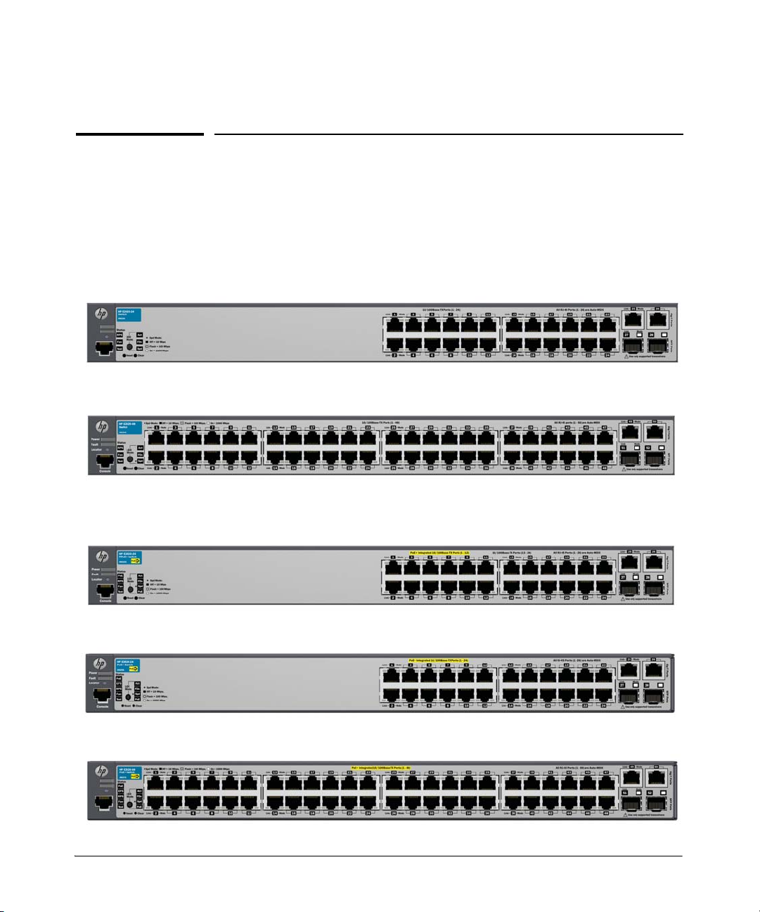
■ The E2620 Switches, have either 24 or 48 auto-sensing 10/100Base-TX RJ-
45 ports with four Gigabit Uplink ports, two RJ-45 and two mini-GBIC
(Small Form Factor Pluggable (SFP)) slots.
The RJ-45 Gigabit Uplink ports are auto-sensing 10/100/1000Base-T. These
ports operate independently, they are not dual-personality and do not support
PoE+ power.
Table 1-1. Optional Network Connectivity, Speeds and Technologies
Transceiver Form-
Factor and
Connector
1
Speed Technology
100 Mbps
1 Gbps
1
For supported transceivers, visit www.hp.com/networking/support.
– In the first textbox, type J4858 (for 100-Mb and Gigabit information).
– Select any of the products that display in the dropdown list.
– Select Product support information. Then click on Manuals and find the Transceiver
Support Matrix.
For technical details of cabling and technologies see "Cabling and Technology Information"
in the appendices.
100-FX Fiber (multimode) LC
100-BX Fiber (single mode) LC
1000-T Copper (twisted-pair) RJ-45
1000-SX Fiber (multimode) LC
1000-LX Fiber (multimode or single mode) LC
1000-LH Fiber (single mode) LC
1000-BX Fiber (single mode) LC
Cabling
SFP ("mini-GBIC")
Connector
The E2620-PoE+ Switches incorporate two additional features. These
switches offer two types of power, one for switch AC operating power, and
the other for Power over Ethernet (PoE+) power:
1-2
Page 13

Introducing the Switch
■ Power-over-Ethernet or PoE+ power - PoE+ technology allows IP
telephones, wireless LAN Access Points and other appliances to receive
power as well as data over existing LAN cabling, without needing to
modify the existing Ethernet infrastructure. The E2620-PoE+ Switches
are designed with an internal PoE+ power supply capable of providing
364 watts of PoE power (126 watts on the E2620-24-PPoE+. The PPoE+
(Partial PoE+) switch provides 24 Ethernet ports, 12 of which can supply
PoE+ power).
All of the Switch E2620-PoE+ ports can provide up to 30 watts (or 4 ports
at 30 watts, or 8 ports at 15.4 watts on the E2620-24-PPoE+) of PoE+ power
to connected devices. For further information regarding PoE/PoE+
power, see the HP Power over Ethernet (PoE/PoE+) Planning and
Implementation Guide, which is on the HP Web site at
www.hp.com/
networking/support.
■ Redundant and External Power Supply Support - The E2620 non-
PoE+ and PPoE+ switches can be connected to an HP 600 Redundant and
External Power Supply (J8168A), hereafter referred to as the 600 RPS/
EPS, for RPS power only. As an RPS unit, the 600 RPS/EPS will provide
all the AC power necessary to keep the switch running should the switch
internal AC power supply fail. The 600 RPS/EPS can not be used for EPS
(PoE+) power for the E2620-PoE+ switches.
■ The E2620 PoE+ switches can be connected to an HP 620 Redundant and
External Power Supply (J8696A), hereafter referred to as the 620 RPS/
EPS, for RPS only. As an RPS unit, the 620 RPS/EPS will provide all the
AC power necessary to keep the switch running should the switch internal
AC power supply fail. The 620 RPS/EPS can not be used for EPS (PoE+)
power for the E2620-PoE+ switches.
■ Also, the E2620 PoE+ switches can be connected to an HP 630 Redundant
and/or External Power Supply (J9443A), hereafter referred to as the 630
RPS/EPS, and receive redundant power from that unit. As an EPS unit,
the 630 RPS/EPS can supply up to 398 watts of PoE power to the switch
if the internal PoE power supply of the switch should fail. When used with
the Switch E2620-48-PoE+, the additional EPS power can provide up to
30 watts per port for 48 ports. For further information regarding the RPS/
EPS PoE+ capabilities, see the HP Power over Ethernet (PoE/PoE+)
Planning and Implementation Guide, or the HP Redundant and/or
External Power Supplies Installation and Getting Started Guide which
is on the HP Web site at
www.hp.com/networking/support.
1-3
Page 14

Introducing the Switch
Table 1-1. RPS/EPS Compatibility Matrix
Switch RPS Support EPS Support
HP E2620-24 (J9623A) 600 N/A
HP E2620-48 (J9626A) 600 N/A
HP E2620-24-PPoE+ (J9624A) 600 N/A
HP E2620-24-PoE+ (J9625A) 620/630 630
HP E2620-48-PoE+ (J9627A) 620/630 630
These switches can be directly connected to computers, printers, and servers
to provide dedicated bandwidth to those devices, and you can build a switched
network infrastructure by connecting the switch to hubs, other switches, or
routers. In addition, the E2620 Switches offer full network management
capabilities.
1-4
Page 15
Front of the Switch
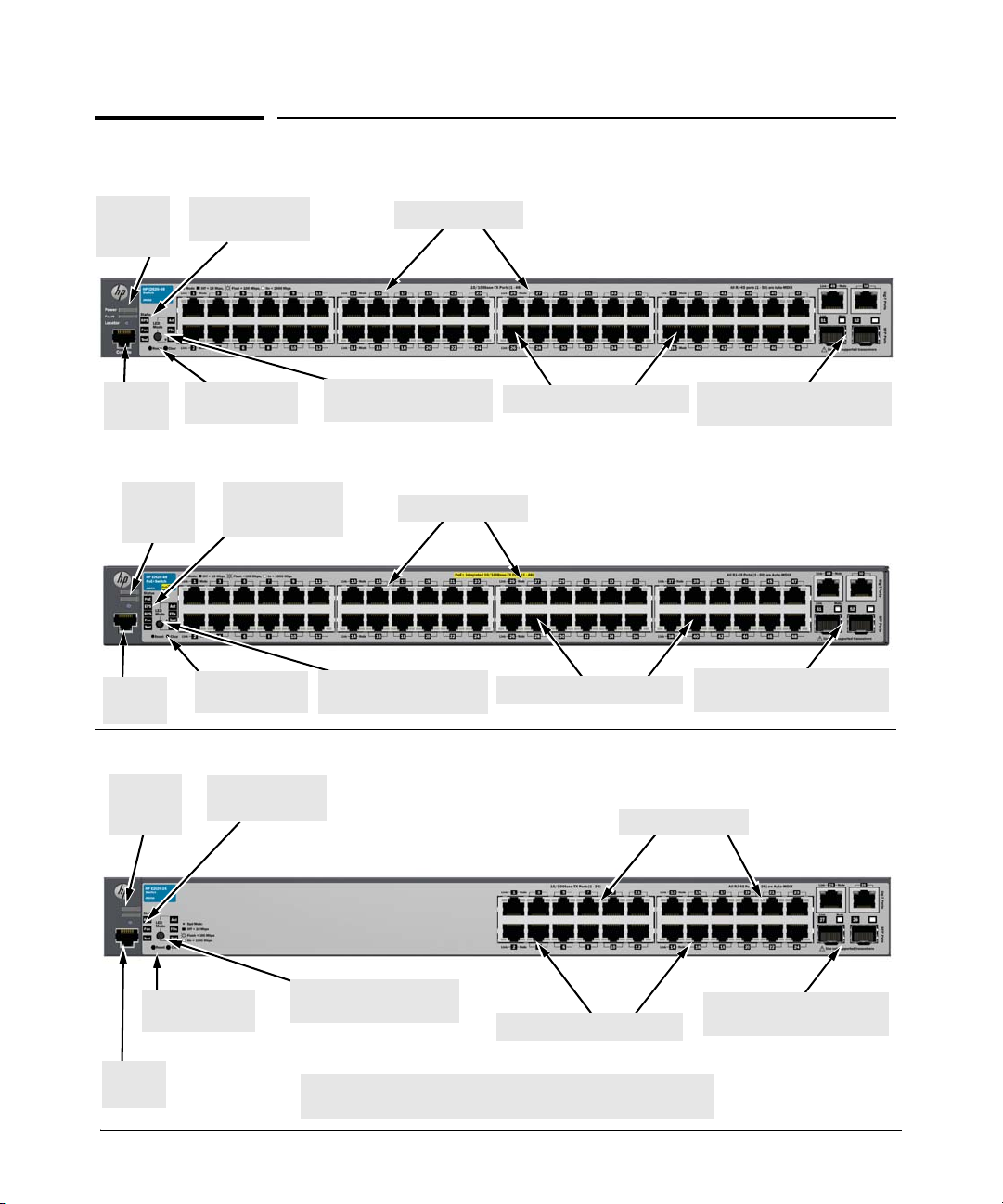
HP E2620-48 Switch (J9626A)
Power
and Fault
LEDs
RPS, Fan and Test
Status LEDs
Switch port LEDs
LED Mode select button
and indicator LEDs
Reset and Clear
buttons
10/100Base-TX RJ-45 ports1
Uplink ports
(1000Base-T
2
and mini-GBIC)
Console
Port
HP E2620-48-PoE+ Switch (J9627A)
Reset and Clear
buttons
LED Mode select button
and indicator LEDs
10/100Base-TX RJ-45 ports1
Uplink ports
(1000Base-T
2
and Mini-GBIC)
Switch port LEDs
RPS, EPS, Fan and
Test Status LEDs
Power
and Fault
LEDs
Console
Port
HP E2620-24 Switch (J9623A)
1
All 10/100Base-TX RJ-45 ports have the Auto-MDIX feature.
2
Two RJ-45 10/100/1000Base-T ports and two Mini-GBIC (SFP) slots.
Console
Port
Reset and Clear
buttons
Switch port LEDs
LED Mode select button
and indicator LEDs
10/100Base-TX RJ-45 ports1
Uplink ports
(1000Base-T
2
and Mini-GBIC)
RPS and Test
Status LEDs
Power
and Fault
LEDs
Introducing the Switch
Front of the Switch
1-5
Page 16

Introducing the Switch
Front of the Switch
Switch LEDs State Meaning
Network Ports
■ 24, or 48 auto-sensing 10/100Base-TX ports.
All these ports have the “Auto-MDIX” feature, which means that you can
use either straight-through or crossover twisted-pair cables to connect
any network devices to the switch.
■ Two RJ-45 10/100/1000Base-T ports for high speed uplink.
■ Two mini-GBIC (SFP) slots for fiber uplinks.
LEDs
On the E2620 Switches, there are three groupings of LEDs:
■ switch status LEDs (Table 1-2)
■ port LEDs (Table 1-3)
■ Port LED Mode indicator LEDs (near the selector button) (Table 1-4)
Table 1-2. Switch Status LEDs
Power
(green)
Fault
(orange)
On The internal power supply is working properly.
Off No power connection. The switch is NOT receiving power.
Flashing2A failure of the internal power supply. It should be flashing simultaneously
with the Fault LED. (If an RPS is connected to the switch, the RPS is
actively powering the switch, the RPS LED will be on.)
Off The normal state; indicates there are no fault conditions on the switch.
Flashing2A fault has occurred with a component on the switch. The Status LED for
the component with the fault will flash simultaneously.
On On briefly after the switch is powered on or reset, at the beginning of
switch self test. If this LED is on for a prolonged time, the switch has
encountered a fatal hardware failure, or has failed its self test. See
chapter 4, “Troubleshooting” for more information.
1-6
Page 17

Switch LEDs State Meaning
Introducing the Switch
Front of the Switch
Locator
(blue)
PoE
(green/
3
orange)
RPS Status
(green/
orange)
EPS Status
(green)
3
On
Flashing
Off
On
Flashing/
orange
Flashing/
orange
On
Flashing
orange
Off
On
The Locator LED is used to locate a specific switch in an area full of
switches. The LED can be set to be on solid or flash for a specified number
of minutes (1-1440). The default is 30 minutes. Use the command
“chassislocate”.
Normal operation. The switch is ready to supply PoE power
One or more ports has experienced a fault condition for PoE delivery. The
2
Fault LED will be flashing simultaneously. If it is a self test failure, the Test
LED will be flashing simultaneously. When the switch is put in PoE LED
Mode, The Mode LED for the port with the problem will also be flashing
simultaneously.
One or more ports has an alert condition for PoE delivery, for example, an
1
oversubscription condition (not enough PoE power available). Only this
LED will be flashing, the Fault LED is off. When the switch is put in PoE
LED Mode, The Mode LEDs for the ports with the alert condition will also
be flashing.
Normal operation. An external power supply is connected and operating
correctly. The external power supply could be powering the unit.
An external power supply is connected but may be powering another
1
switch or the external power supply has experienced a fault. Only this
LED flashes, the Fault LED is off.
An external power supply is not connected.
The switch is connected to an external power supply and operating
correctly.
Fan
(green/
orange)
Flashing
orange
The external power supply has experienced a fault:
1
• There is a fan, overcurrent, power supply, or temp fault on the EPS.
• The Switch detects the EPS is present but cannot communicate with it.
Check the Error Log on the switch for more information.
The switch is not connected to an external power supply or the EPS cable
Off
is connected but the external power supply is not powered up.
On The cooling fan is operating normally.
Flashing
orange
The cooling fan has failed. The switch Fault LED will be flashing
2
simultaneously.
1-7
Page 18

Introducing the Switch
Front of the Switch
Switch LEDs State Meaning
Te st
(green/
orange)
Off The normal operational state; the switch is not undergoing self test.
On The switch self test and initialization are in progress after the switch has
been power cycled or reset. The switch is not operational until this LED
goes off. The Test LED also comes on briefly when you “hot swap” a miniGBIC into the switch; the mini-GBIC is tested when it is hot swapped.
Flashing
orange
1
The flashing behavior is an on/off cycle once every 0.8 seconds approximately, a fast flash.
2
The flashing behavior is an on/off cycle once every 1.6 seconds approximately, a slow flash.
3
HP E2620-24-PoE+ (J9625A) and HP E2620-48-PoE+ Switch (J9627A) Switches only.
A component of the switch has failed its self test. The switch Fault LED,
2
Test LED, and the failed component LED will flash simultaneously.
See the HP Redundant and/or External Power Supply Installation and
Getting Started Guide for information on the LED behavior of the external
power supplies.
1-8
Page 19

Port LEDs
The port LEDs provide information about the individual switch ports.
Table 1-3. Port LEDs
Switch LEDs State Meaning
E2620 non-PoE Switches
Introducing the Switch
Front of the Switch
Port LEDs Displays port link information, network activity information, whether the port is
Mini-GBIC
LEDs:
Link Flashing
Link and Mode
(green)
Switch E2620-PoE Switches
Link
(green)
configured for full-duplex operation, or the speed of the connection depending on the
LED Mode selected. See “LED Mode Select Button and Indicator LEDs” on the next page
for more information.
One of the following conditions exist:
orange
On for 2
seconds
On The port is enabled and receiving a link indication from the connected
Off One of these condition exists:
• the mini-GBIC is not supported by the current software
• the mini-GBIC is not a genuine HP Mini-GBIC and is not supported
• the mini-GBIC is an “A” version in a switch that requires a “B” version
or later.
Both the Link and Mode LED turn on solid for 2 seconds and then go to
normal operation. This indicates the mini-GBIC has been recognized by the
switch.
device. In PoE+ mode, indicates that the port is configured to enable PoE
power delivery to the connected device.
• no active network cable is connected to the port
• the port is not receiving link beat or sufficient light
• the port has been disabled through the switch console, the web browser
interface, ProCurve Manager, or other network management tool.
• In PoE+ mode, indicates that the port is configured such that PoE+ power
delivery is disabled.
Flashing
Mode (green) Depending on the mode selected, displays the following:
• Connection speed information
• network activity information
• PoE+ power delivery status
See “LED Mode Select Button and Indicator LEDs:” below for more information.
1
The flashing behavior is an on/off cycle once every 1.6 seconds, approximately.
1
The port has failed self test. The switch Fault, and Self Test LEDs will flash
simultaneously.
1-9
Page 20
Introducing the Switch
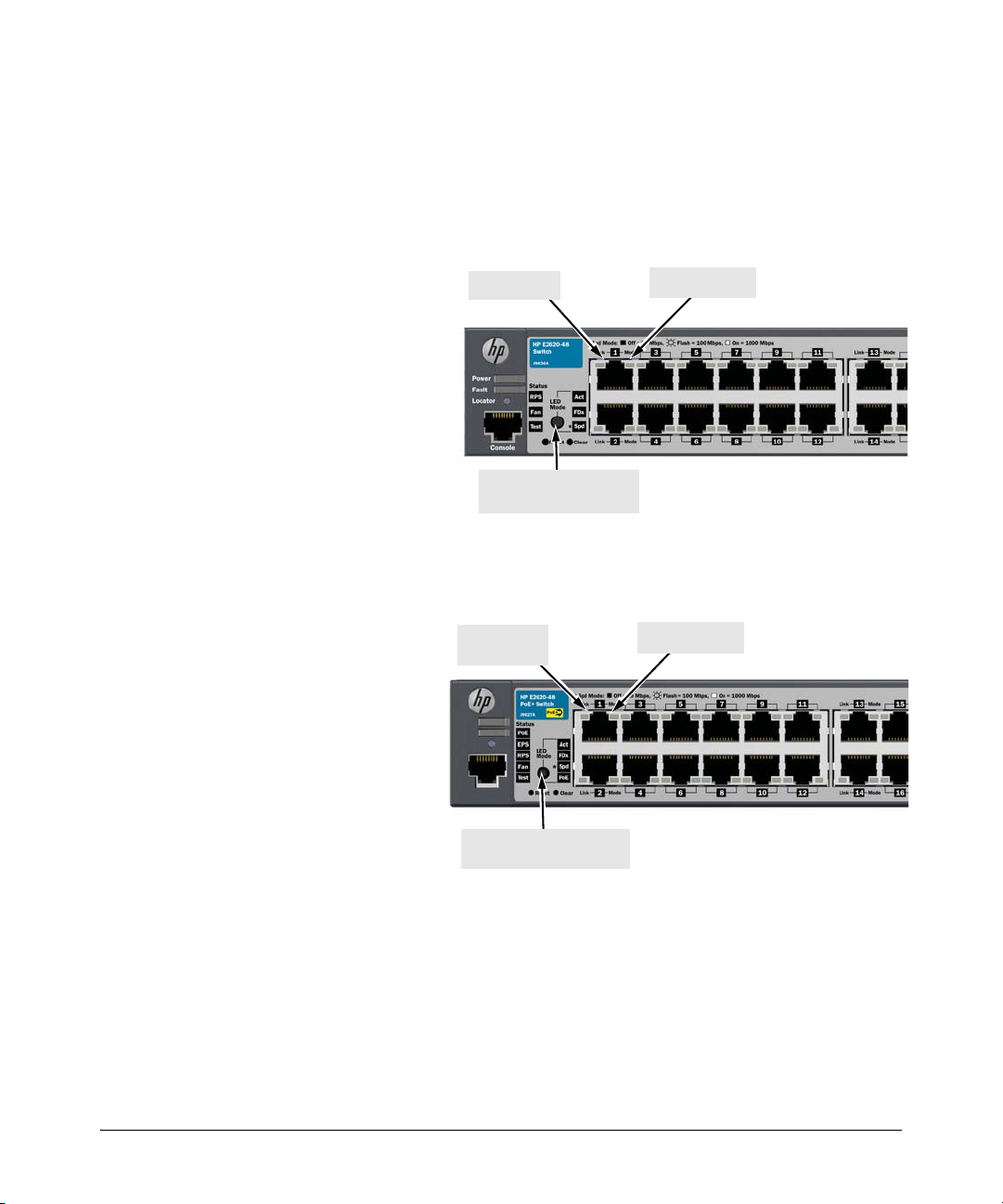
Mode LED
Link LED
LED Mode select button
and indicator LEDs
The non-PoE+ switches, have two
LEDs per port. The Link status is always shown by the Link LED. The operation of the Mode LED is controlled
by the LED Mode select button, and
the current setting is indicated by the
LED Mode indicator LEDs near the
button. Press the button to step from
one view mode to the next. The default view is Activity (Act).
Link LED
(port number)
LED Mode select button
and indicator LEDs
The PoE+ switches also have two
LEDs per port. The Link status is
always shown by the Link LED as
with the non-PoE switches. The
operation of the Mode LED is the
same as the non-PoE switches. The
difference is the PoE+ switches have
an additional mode, and that is
PoE+. In PoE+ mode, the Link LED
indicates the PoE+ configuration for
the port: On if PoE+ is enabled on
the port; Off if PoE+ is disabled on
the port. The default view is Activity
(Act).
Mode LED
Front of the Switch
LED Mode Select Button and Indicator LEDs
To optimize the amount of information that can be displayed for each of the
switch ports in the limited space available, the E2620 Switches use multipledisplay LEDs for each port.
Figure 1-2. E2620 non-PoE Switches
1-10
Figure 1-3. E2620-PoE+ Switches
Page 21

Table 1-4. Multiple-Display Port LEDs
Switch LEDs State Meaning
All E2620 Switches
Introducing the Switch
Front of the Switch
Port LED View
indicator LEDs
3 green LEDs)
Switch E2620-PoE+ Series
LED Mode
indicator LEDs
(PoE+ is the
additional
LED, green)
Act
FDx
Spd
PoE+ Indicates the Port LEDs are lit for ports that are providing PoE+ power to the
Reset Button
This button is for:
■ Resetting the switch - When the switch is powered on. This action clears
any temporary error conditions that may have occurred and executes the
switch self test.
■ Restoring Factory Default Configuration - When pressed with the
Clear button in a specific pattern, any configuration changes you may have
made through the switch console, the web browser interface, and SNMP
management are removed, and the factory default configuration is
restored to the switch. For the specific method to restore the factory
default configuration, see “Restoring the Factory Default Configuration”
on page 12, “Troubleshooting” of this manual.
Indicates the Port LEDs are displaying network activity information.
Indicates the Port LEDs are lit for ports that are in full-duplex mode.
Indicates the Port LEDs are displaying the connection speed at which each
port is operating:
• if the Port LED is off, the port is operating at 10 Mbps.
• if the Port LED is flashing, the port is operating at 100 Mbps.
• if the Port LED is on continuously, the port is operating at 1000 Mbps.
connected device.
Clear Button
This button is used for:
■ Deleting Passwords - When pressed by itself for at least one second, the
button deletes any switch console access passwords that you may have
configured. Use this feature if you have misplaced the password and need
console access. This button is provided as a convenience, however if you
are concerned with the security of the switch configuration and operation,
you should make sure the switch is installed in a secure location. This
button can be disabled by a CLI command.
■ Restoring Factory Default Configuration - See Reset Button above.
1-11
Page 22
Introducing the Switch
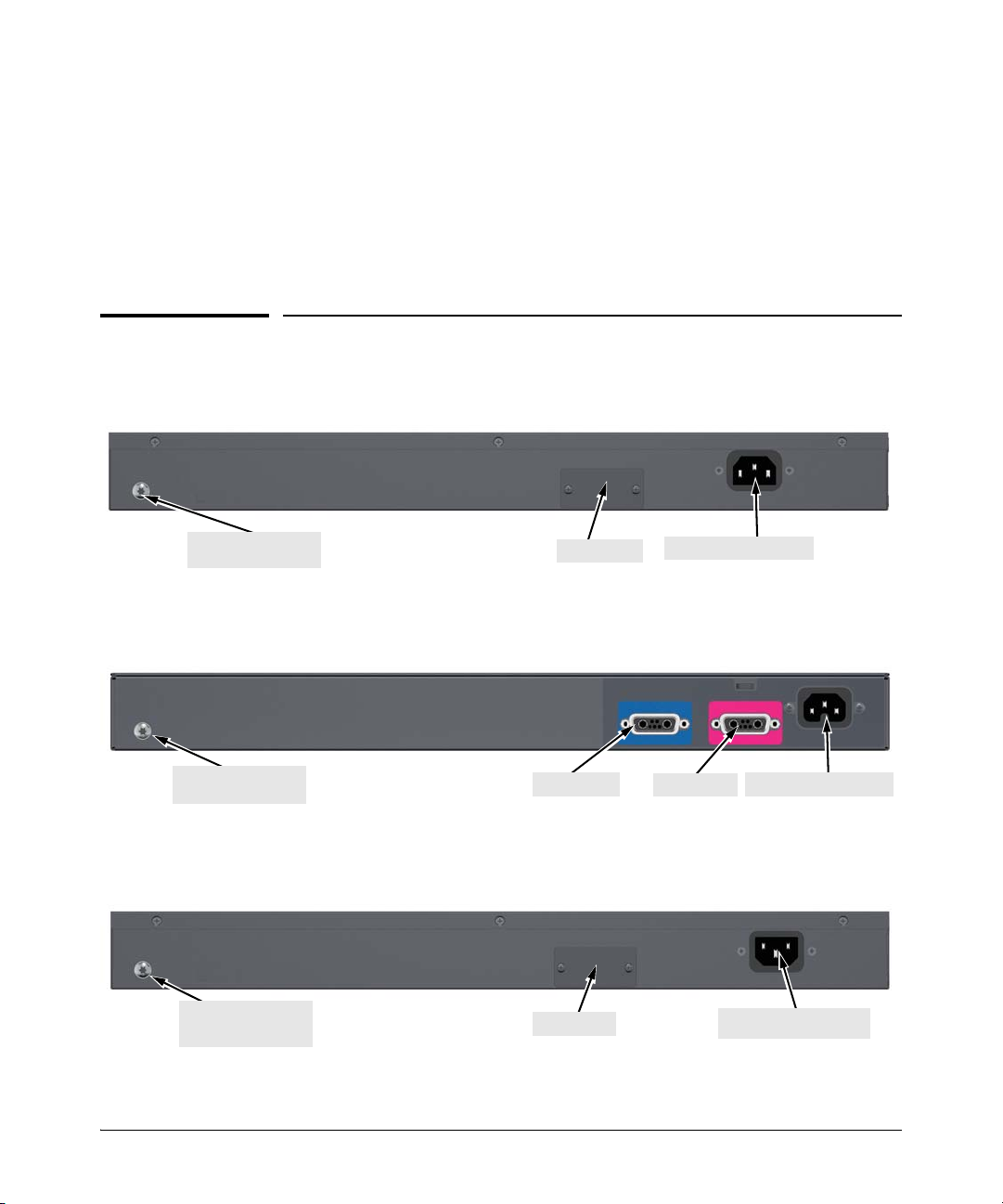
AC power connector
Attach grounding lug
(optional)
RPS Input
AC power connector
RPS Input
Attach grounding lug
(optional)
EPS Input
AC power connector
RPS Input
Attach grounding lug
(optional)
Back of the Switch
Console Port
This port is used to connect a console to a E2620 Switches by using the
RJ-45 to DB9 cable, supplied with the switch. This connection is described
under “8. (Optional) Connect a Console to the Switch” on page 25 in chapter
2, “Installing the Switch.” The console can be a PC or workstation running a
VT-100 terminal emulator, or a VT-100 terminal.
Back of the Switch
Figure 1-4. HP Switch E2620-24 and E2620-48 non-PoE+
Figure 1-5. HP Switch E2620-24-PoE+ and E2620-48-PoE+
Figure 1-6. HP Switch 2620-24-PPoE+
1-12
Page 23

Introducing the Switch
Switch Features
RPS and EPS Input Port
The E2620 Switches support connectivity to three external power supplies
denpending on the switch to be supported.
■ The HP 600 Redundant and External Power Supply (J8168A) can be
connected to:
• E2620-24 (J9623A)
• E2620-48 (J9626A)
• E2620-24-PPoE+ (J9624A)
For RPS power only. EPS power is not supported on these switches.
■ The HP 620 Redundant and External Power Supply (J8696A) and the HP
630 Redundant and/or External Power Supply (J9443A) can be connected
to:
• E2620-24-PoE+ (J9625A)
• E2620-48-PoE+ (J9627A)
The RPS functionality of these external power supplies provide redundant
system power in case the switch’s internal power supply fails. The EPS
functionality of the 630 provides additional PoE+ power. The E2620
Switches do not support EPS power from the 620 RPS/EPS. Also refer to
the RPS/EPS Compatibility Matrix on page 1-4.
Power Connector
The E2620 Switches and E2620-PoE+ Switches do not have a power switch;
they are powered on when connected to an active AC power source. The
switches automatically adjust to any voltage between 100-127 and 200-240
volts and either 50 or 60 Hz. There are no voltage range settings required.
Switch Features
The features of the E2620 Switches and E2620-PoE+ Switches include:
■ 24, or 48 auto-sensing 10/100Base-TX RJ-45 ports with Auto-MDIX.
■ 4 Uplink ports—two are 1000Base-T RJ-45 and two are mini-GBIC (SFP)
slots.
1-13
Page 24

Introducing the Switch
Switch Features
■ Power over Ethernet (PoE/PoE+) operation—the E2620-PoE+ Switches
are IEEE 802.3at compliant and provide up to 30W per port to power IP
phones, wireless access points, web cameras, and more. For more
information, see the HP Power over Ethernet (PoE/PoE+) Planning and
Implementation Guide, which is on the HP Web site at
www.hp.com/
networking/support.
■ The E2620-PoE+ Switches support some pre-standard PoE devices.
However, the use of a cross-over cable may be required. For a current list
see the FAQ page for the E2620-PoE+ Switch, which can be found on the
HP Web site,
■ Plug-and-play networking—all ports are enabled—just connect the
www.hp.com/networking/support.
network cables to active network devices and your switched network is
operational.
■ Auto-MDIX on all twisted-pair ports, 10/100 and 10/100/1000, meaning that
all twisted-pair connections can be made using straight-through cables.
Cross-over cables are not required, although they will also work.
■ Automatic learning of the hardware addresses in each switch’s 8000-
address forwarding table, (with configurable address aging value).
■ Automatically negotiated full-duplex operation for the 10/100 and
10/100/1000 RJ-45 ports when connected to other auto-negotiating
devices—the mini-GBIC ports always operate at full duplex, unless a
100-FX SFP transceiver is installed. The 100-FX SFP transceiver can
operate at half duplex.
■ Easy management of the switches through several available interfaces:
• console interface—a full featured, easy to use, VT-100 terminal
interface that is especially good for out-of-band switch management
or for Telnet access to the switch.
• web browser interface—an easy to use built-in graphical interface
that can be accessed from common web browsers.
• ProCurve Manager—an SNMP-based, graphical network
management tool that you can use to manage your entire network.
■ Support for the Spanning Tree Protocol to eliminate network loops
■ Support for up to 512 IEEE 802.1Q-compliant VLANs so you can divide
the attached end nodes into logical groupings that fit your business needs.
■ Download of new switch software for product enhancements or bug fixes.
■ Variable-speed fans to maintain cooling.
■ Support for many advanced features to enhance network performance—
for a description, see the Management and Configuration Guide, which
is on the HP Web site at
www.hp.com/networking/support.
1-14
Page 25

Installing the Switch
The HP E2620 Switches come with an accessory kit that includes the brackets
for mounting the switch in a standard 19-inch telco rack, or in an equipment
cabinet. The brackets for the non-PoE+ 2620 models also allow them to be
mounted on a wall. The brackets are designed to allow mounting the switch
in a variety of locations and orientations. Rubber feet are provided that can
be attached so the switch can be securely located on a horizontal surface. This
chapter shows how to install the E2620 Switches.
Included Parts
The E2620 Switches have the following components:
■ HP Switch Quick Setup Sheet
■ Read Me First
■ HP Switches General Safety and Regulatory Information booklet
■ E2620 Switch Specific Safety and Regulatory Information sheet
■ Console cable
■ Customer Support/Warranty booklet
■ Accessory kits:
Installing the Switch
Included Parts
2
E2620 Non-PoE+ switches and
the J9624A 24-port PPoE+ switch
Kit number 5069-6535
Contains:
• two mounting brackets
• eight 8-mm M4 screws to attach the
mounting brackets to the switch
• four 5/8-inch number 12-24 screws to
attach the switch to a rack
• four rubber feet
1
The mounting brackets in this kit are longer to support the increased depth of the E2620-
PoE+ products. They cannot be used to wall mount the PoE+ switches.
E2620-PoE+ switches, J9625A
and J9627A
Kit number 5069-5705
Contains:
• two mounting brackets
• eight 8-mm M4 screws to attach the
mounting brackets to the switch
• four 5/8-inch number 12-24 screws to
attach the switch to a rack
• four rubber feet
1
2-1
Page 26

Installing the Switch
Included Parts
AC power cord, one of the following:
Japan Power
Cord Warning
Country/Region Non-PoE+ and PPoE+
Australia/New Zealand
China
Continental Europe
Denmark
Japan
Switzerland
United Kingdom/Hong Kong/Singapore
South Africa
Thailand
Taiwan
United States/Canada/Mexico
Israel
Chile
Brazil
Argentina
1
The cords for the PoE+ Switches support a higher amperage and a C15 connector.
Switches
8121-0834
8120-8377
8120-6802
8120-6806
8120-6804
8120-6807
8120-6809
8121-0919
8121-0673
8121-0964
8120-6805
8121-1035
8120-6980
8121-1069
8120-6869
PoE+ Switches
8121-0857
8121-1034
8120-5336
8120-5340
8120-5342
8120-5339
8120-5334
8120-5341
8121-0671
8121-0967
8121-0973
8121-1009
8120-8389
8121-1132
8120-8375
1
2-2
Page 27

Installing the Switch
Included Parts
Installation Precautions
WARNINGS ■ The rack or cabinet should be adequately secured to prevent it
from becoming unstable and/or falling over.
Devices installed in a rack or cabinet should be mounted as low as
possible, with the heaviest devices at the bottom and progressively
lighter devices installed above.
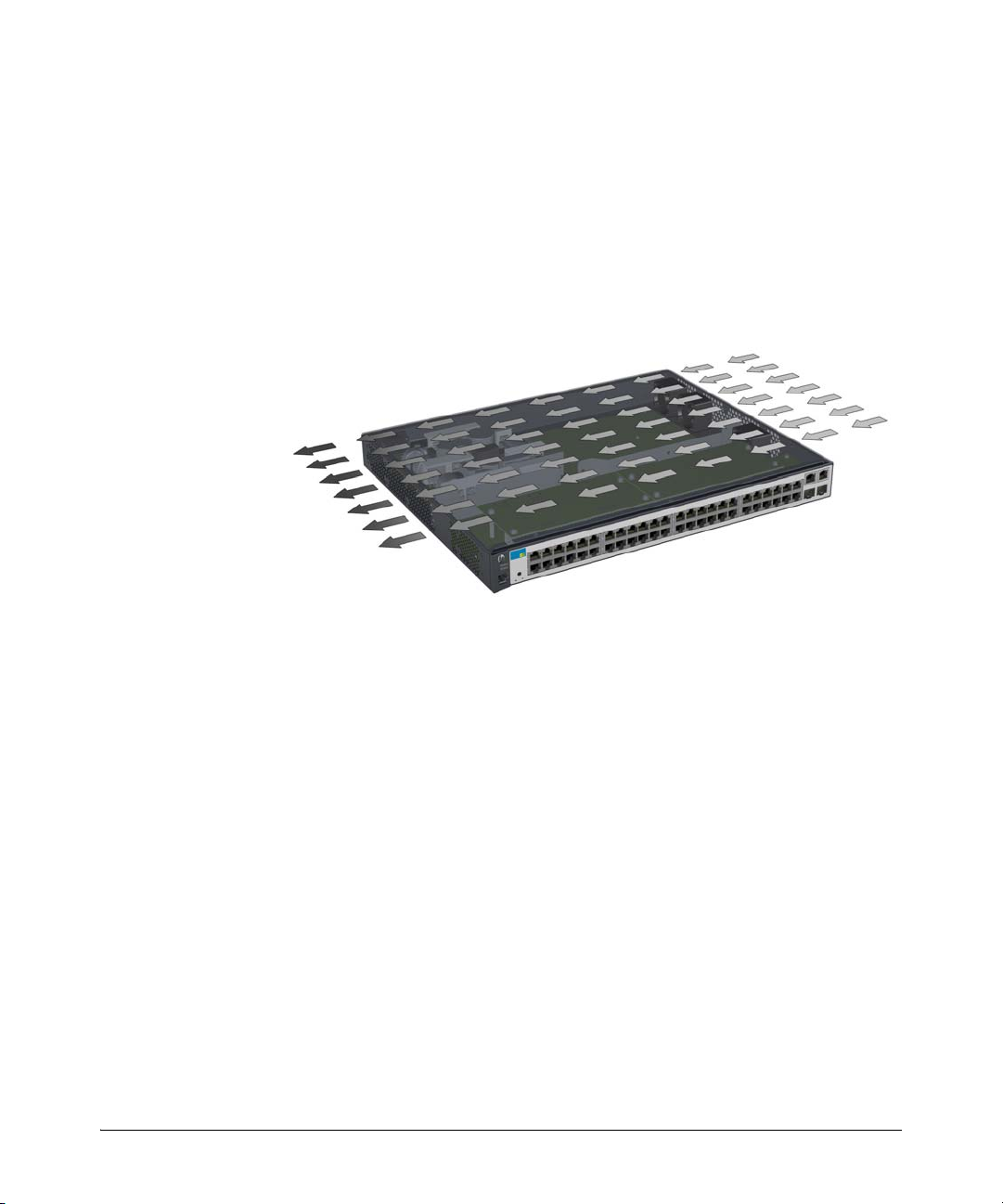
■ For safe operation do not install the switch with the side of the
switch (with the fan vents) facing either downward or upward.
Cautions ■ If one of the following switches is to be mounted in a rack, you can use a
rack kit, J9583A - HP X410 1U Universal 4-Post Rack Mounting Kit for the
following switches only:
• J9085A HP Switch E2620-24
• J9088A HP Switch E2620-48
• J9086A HP Switch E2620-24-PPoE+
■ Ensure the power source circuits are properly grounded, then use the
power cord supplied with the switch to connect it to the power source.
■ If your installation requires a different power cord than the one supplied
with the switch, ensure the cord is adequately sized for the switch’s
current requirements. In addition, be sure to use a power cord displaying
the mark of the safety agency that defines the regulations for power cords
in your country. The mark is your assurance that the power cord can be
used safely with the switch. If the PoE+ device’s supplied power cord does
not fit, contact HP networking support.
■ When installing the switch, the AC outlet should be near the switch and
should be easily accessible in case the switch must be powered off.
■ Ensure the switch does not overload the power circuits, wiring, and over-
current protection. To determine the possibility of overloading the supply
circuits, add together the ampere ratings of all devices installed on the
same circuit as the switch and compare the total with the rating limit for
the circuit. Maximum ampere ratings are usually printed on the devices
near the AC power connectors.
■ Do not install the switch in an environment where the operating ambient
temperature might exceed 55°C (131°F). This includes a fully-enclosed
rack. Ensure the air flow around the sides and back of the switch is not
restricted. Leave at least 7.6 cm (3 inches) for cooling.
■ Ensure all port covers are installed when the port is not in use.
2-3
Page 28

Installing the Switch
Installation Procedures
Installation Procedures
These steps summarize your switch installation. The rest of this chapter
provides details on these steps.
1. Prepare the installation site (page 2-6). Make sure the physical
environment into which you will be installing the switch is properly
prepared, including having the correct network cabling ready to connect
to the switch and having an appropriate location for the switch. See page
2-3 for some installation precautions.
2. Verify the switch passes self test (page 2-6). Plug the switch into a
power source and observe that the LEDs on the switch’s front panel
indicate correct switch operation.
3. Mount the switch (page 2-9). The E2620 Switches can be mounted in a
19-inch telco rack, in an equipment cabinet, or on a horizontal surface.
The non-PoE+ E2620 Switches can also be wall mounted. See page 2-14
for wall mounting instructions.
The following switches can be rack mounted with rack kit, J9583A - HP
X410 1U Universal 4-Post Rack Mounting Kit.
• J9623A HP Switch E2620-24
• J9626A HP Switch E2620-48
• J9624A HP Switch E2620-24-PPoE+
2-4
4. Connect power to the switch (page 2-15). Once the switch is mounted,
plug it into the main power source.
5. Connect the network devices (page 2-15). Using the appropriate
network cables, connect the network devices to the switch ports.
6. (Optional) Install mini-GBICs (page 2-17). The switch has two slots
for installing mini-GBICs. Depending on where you install the switch, it
may be easier to install the mini-GBICs first. Mini-GBICs can be hot
swapped—they can be installed or removed while the switch is powered
on.
7. (Optional) Connect an External Power Supply to the Switch (page
2-19). You may wish to use a 600 RPS/EPS, 620 RPS/EPS, or 630 RPS/EPS
with your E2620-PoE+ Switches. To do so you must connect these
external power supplies using the RPS or EPS cables supplied with these
devices.
Page 29
Installing the Switch
Installation Procedures
8. (Optional) Connect a console to the switch (page 2-25). You may
wish to modify the switch’s configuration, for example, to configure an IP
address so it can be managed using a web browser, from an SNMP network
management station, or through a Telnet session. Configuration changes
can be made by using the included console cable to connect a PC to the
switch’s console port.
At this point, your switch is fully installed. See the rest of this chapter if you
need more detailed information on any of these installation steps.
Figure 2-1. Air flow direction of the E2620 switches
2-5
Page 30
Installing the Switch
Connect power cord to
the power connector
Installation Procedures
1. Prepare the Installation Site
Cabling Infrastructure - Ensure the cabling infrastructure meets the
necessary network specifications. See the following table for cable types and
lengths, and see appendix B, “Cabling and Technology Information” for more
information:
■ Installation Location - Before installing the switch, plan its location and
orientation relative to other devices and equipment:
• In the front of the switch, leave at least 7.6 cm (3 inches) of space for
the twisted-pair and fiber-optic cabling.
• In the back of the switch, leave at least 3.8 cm (1 1/2 inches) of space
for the power cord.
• On the sides of the switch, leave at least 7.6 cm (3 inches) for cooling.
2. Verify the Switch Passes Self Test
Before mounting the switch in its network location, you should first verify it
is working properly by plugging it into a power source and verifying it passes
its self test.
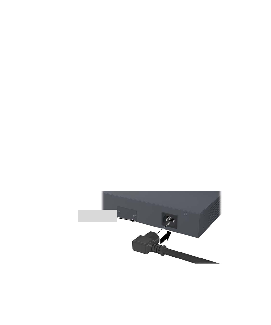
1. Connect the power cord supplied with the switch to the power connector
on the back of the switch, and then into a properly grounded electrical
outlet.
Figure 2-2. Example of connecting the power cord
2-6
Page 31

Installing the Switch
Power and
Fault LEDs
Self Test LED
Switch port LEDs
Installation Procedures
Note The E2620 Switches do not have a power switch. They are powered on when
the power cord is connected to the switch and to a power source. For safety,
the power outlet should be located near the switch installation.
The switch automatically adjusts to any voltage between 100-127 or 200-240
volts and either 50 or 60 Hz. There are no voltage range settings required.
If your installation requires a different power cord than the one supplied with
the switch, be sure the cord is adequately sized for the switch’s current
requirements. In addition, be sure to use a power cord displaying the mark of
the safety agency that defines the regulations for power cords in your country.
The mark is your assurance that the power cord can be used safely with the
switch. If the PoE+ device’s supplied power cord does not fit, contact HP
networking support.
2. Check the LEDs on the switch as described below.
Figure 2-3. Checking the LEDs on the E2620 non-PoE+ switches
2-7
Page 32

Installing the Switch
Power and
Fault LEDs
Self Test LED Switch port LEDs
Installation Procedures
When the switch is powered on, it performs its diagnostic self test. Self test
takes approximately 50 seconds to complete.
Figure 2-4. Checking the LEDs on the E2620-PoE+ switches
LED Behavior
During the self test:
• Initially, all the switch and port LEDs are on. Most of the LEDs go off
and then may come on again during phases of the self test.
• For the duration of the self test, the Self Test LED stays on.
2-8
When the self test completes successfully:
•The Power and Fan LEDs remain on.
•The Fault and Tes t LEDs go off.
• The port LEDs on the front of the switch go into their normal opera-
tional mode:
– If the ports are connected to active network devices, the LEDs
behave according to the Port LED View or LED Mode selected.
The default view mode (Link), the LEDs should be on and the
Mode LEDs will flicker if there is network activity.
– If the ports are not connected to active network devices, the Link
and Act LEDs will stay off.
If the LED display is different than what is described above, especially if
the Fault and Te st LEDs stay on for more than 60 seconds or they start
flashing, the self test has not completed correctly. Refer to chapter 4,
“Troubleshooting” for diagnostic help.
Page 33

Installing the Switch
Installation Procedures
3. Mount the Switch
After the switch passes self test, it is ready to be mounted in a stable location.
The E2620 Switches can be mounted in these ways:
Mounting Location Non-PoE+ Switches PoE+ Switches
In a rack or cabinet Yes Yes
On a horizontal surface Yes Yes
On a wall Yes
Under a desk Yes
1
This also includes the E2620-24-PPoE+ Switch (J9624A).
2
RJ-45 ports facing up only.
Rack or Cabinet Mounting
The E2620 Switches are designed to be mounted in any EIA-standard 19-inch
telco rack or communication equipment cabinet. Note that the mounting
brackets have multiple mounting holes and can be rotated allowing for a wide
variety of mounting options. Secure the rack in accordance with the
manufacture’s safety guidelines.
1,2
1
No
No
WARNING For safe operation, please read the mounting precautions on
page 2-3, before mounting a switch.
Equipment
Cabinet
Note
The 12-24 screws supplied with the switch are the correct threading for
standard EIA/TIA open 19-inch racks. If installing the switch in an equipment
cabinet such as a server cabinet, use the clips and screws that came with the
cabinet in place of the 12-24 screws that are supplied with the switch.
2-9
Page 34

Installing the Switch
Installation Procedures
Rack Mounting the E2620-PoE+ switches
1. Use a #1 Phillips (cross-head) screwdriver and attach the mounting
brackets to the switch with the included 8-mm M4 screws.
Figure 2-5. Attaching large mounting brackets
WARNING For safe reliable installation, only use the screws provided in the
accessory kit to attach the mounting brackets to the switch.
Note The mounting brackets have multiple mounting holes and can be rotated
allowing for a wide variety of mounting options. These include mounting the
switch so that its front face is flush with the face of the rack, or mounting it
in a more balanced position as shown in the illustration above.
2. Hold the switch with attached brackets up to the rack and move it
vertically until rack holes line up with the bracket holes, then insert and
tighten the four number 12-24 screws holding the brackets to the rack.
2-10
Page 35

Installing the Switch
Install 12-24
screws
Installation Procedures
Figure 2-6. Mounting in a rack
2-11
Page 36

Installing the Switch
8 mm
M4 screws
Installation Procedures
Rack Mounting the Non-PoE+ Switches
1. Use a #1 Phillips (cross-head) screwdriver and attach the mounting
brackets to the switch with the included 8-mm M4 screws.
Figure 2-7. Attaching small mounting brackets
Note The mounting brackets have multiple mounting holes and can be rotated
allowing for a wide variety of mounting options. These include mounting the
switch so that its front face is flush with the face of the rack, or mounting it
in a more balanced position as shown in the illustration.
WARNING For safe reliable installation, only use the screws provided in the
accessory kit to attach the mounting brackets to the switch.
2-12
Page 37

Installing the Switch
Install 12-24
screws
Installation Procedures
2. Hold the switch with attached brackets up to the rack and move it
vertically until rack holes line up with the bracket holes, then insert and
tighten the four number 12-24 screws holding the brackets to the rack.
Figure 2-8. Mounting in a rack
2-13
Page 38

Installing the Switch
M4 screws
Wall
5/8-inch
wood screws
RJ-45 Ports
Installation Procedures
Flat Wall Mounting (non-PoE+ models only)
You can mount the non-PoE+ 2620 models on a wall. They should be mounted
with the RJ-45 ports facing up as shown in Figure 2-9.
WARNING For safe operation do not install the switch with either side vent holes
facing downward.
Caution The switch should be mounted only to a wall or wood surface that is at least
1/2-inch (12.7 mm) plywood or its equivalent.
1. Use a #1 Phillips (cross-head) screwdriver and attach the mounting
brackets to the switch with the included 8-mm M4 screws.
2. Attach the switch to the wall or wood surface with two 5/8-inch number
12 wood screws (not included).
Figure 2-9. Wall mounting RJ-45 ports facing up
2-14
Page 39

Installing the Switch
Installation Procedures
Horizontal Surface Mounting
Place the switch on a table or other horizontal surface. The switch comes with
rubber feet in the accessory kit that can be used to help keep the switch from
sliding on the surface.
Attach the rubber feet to the four corners on the bottom of the switch within
the embossed angled lines. Use a sturdy surface in an uncluttered area. You
may want to secure the networking cables and switch power cord to the table
leg or other part of the surface structure to help prevent tripping over the
cords.
Caution Ensure the air flow is not restricted around the sides and back of the switch.
4. Connect the Switch to a Power Source
1. Plug the included power cord into the switch’s power connector and into
a nearby AC power source. See page 2-6.
2. Re-check the LEDs during self test. See “LED Behavior” on page 2-8.
5. Connect the Network Cables
Connect the network cables, described under “Cabling Infrastructure” (page
2-6), from the network devices or your patch panels to the fixed RJ-45 ports
on the switch or to any mini-GBICs you have installed in the switch.
2-15
Page 40

Installing the Switch
RJ-45 connector
Unshielded twisted-pair cable:
• Category 3, 4, or 5 for 10 Mbps ports
• Category 5 or better for 100 Mbps ports
• Category 5e or better for 1000 Mbps ports
Maximum distance: 100 meters
Figure 2-10. Connecting network cables
Installation Procedures
Using the RJ-45 Connectors
To connect:
Push the RJ-45 plug into the RJ-45
port until the tab on the plug clicks
into place. When power is on for the
switch and for the connected device,
the Link LED for the port should
light to confirm a powered-on d evice
(for example, an end node) is at the
other end of the cable.
If the Link LED does not go on when
the network cable is connected to
the port, see “Diagnosing With the
LEDs” in chapter 4,
“Troubleshooting”.
To disconnect:
Press the small tab on the plug and
pull the plug out of the port.
2-16
Page 41

Installing the Switch
Installation Procedures
6. Installing or removing SFP transceivers (mini-GBICs)
You can install or remove an SFP (mini-GBIC) from an SFP slot without having
to power off the switch. Use only HP SFP transceivers.
Notes ■ The SFP slots are not shared with the two 10/100/1000Base-T RJ-45 ports.
When an SFP is installed in a slot, it operates independently of the RJ-45
ports.
■ The SFP ports operate only at full duplex. Half duplex operation is not
supported, unless a 100-FX SFP transceiver is installed. The 100-FX SFP
transceiver can operate at half duplex.
■ Ensure the network cable is NOT connected when you install or remove
an SFP.
Caution Use only supported genuine HP SFP transceivers with your switch. Non-HP
SFP transceivers are not supported, and their use may result in product
malfunction. Should you require additional HP SFP transceivers, contact your
HP networking Sales and Service Office or authorized dealer.
Installing the SFP transceivers:
Remove the protective plastic cover and retain it for later use. Hold the SFP
transceiver by its sides and gently insert it into either of the slots on the switch
until the transceiver clicks into place.
WARNING The HP SFP transceivers are Class 1 laser devices. Avoid direct eye
exposure to the beam coming from the transmit port.
2-17
Page 42

Installing the Switch
Installation Procedures
Figure 2-11. Installing an SFP transceiver
Removing the SFP transceiver
Note You should disconnect the network cable from the SFP transceiver before
removing it from the switch.
Depending on when you purchased your HP SFP transceiver, it may have
either of three different release mechanisms: a plastic tab on the bottom of
the transceiver, a plastic collar around the transceiver, or a wire bail.
To remove the transceivers that have the plastic tab or plastic collar, push the
tab or collar toward the switch until you see the transceiver release from the
switch (you can see it move outward slightly), and then pull it from the slot.
To remove the transceivers that have the wire bail, lower the bail until it is
approximately horizontal, and then using the bail, pull the transceiver from
the slot.
Replace the protective plastic cover on the transceiver.
Connecting Cables to SFP transceivers
If you have any SFP transceivers installed in the switch, the type of network
connections you will need to use depends on the type of transceivers you have
installed. See appendix B, “Cabling and Technology Information”, for cabling
information.
For SFP transceiver ports, and in general for all the switch ports, when a
network cable from an active network device is connected to the port, the port
LED for that port should go on. If the port LED does not go on when the
2-18
Page 43

Installing the Switch
Installation Procedures
network cable is connected to the port, see “Diagnosing with the LEDs” in
chapter 4, “Troubleshooting”.
7. (Optional) Connect an External Power Supply to the
Switch
There are three external power supplies available for these switches:
■ HP 600 Redundant and External Power Supply, J8168A, is an accessory
product for the E2620 switches and specific other HP switches.
■ HP 620 Redundant and External Power Supply, J8696A, is an accessory
product for the E2620 switches and specific other HP switches.
■ HP 630 Redundant and/or External Power Supply, J9443A, is an accessory
product for the E2620-PoE+ switches and specific other HP PoE+
switches.
The external power supplies provide two types of power to the switches:
■ Redundant power, to back up the internal switch power supply in case of
AC power loss, or a fault condition. Should the internal switch power
supply fail, power will be supplied from the external power supply.
■ External Power-over-Ethernet (PoE/PoE+) power. The external power
supplies can supply PoE/PoE+ power to the switch if the internal PoE/
PoE+ power supply fails. For the 48 port switch, the external PoE/PoE+
power is additional power made available to the switch’s ports.
For further information regarding the external power supply PoE/PoE+
capabilities, see the following manuals:
• HP Power over Ethernet (PoE/PoE+) Planning and Implementation
Guide
• HP Redundant and/or External Power Supply Installation and
Getting Started Guide
These manuals are on the HP Web site at
www.hp.com/networking/support.
These external power supplies are unmanaged power supplies that only
provide information by way of LEDs.
2-19
Page 44

Installing the Switch
Installation Procedures
RPS/EPS Operation
The RPS/EPS monitors the power signal from the switch by detecting that the
RPS/EPS is connected to a switch with an RPS/EPS cable. When the power
from the switch is no longer detected, the RPS/EPS will provide power to the
switch within 1 millisecond.
The RPS/EPS supports hot plugging of the RPS/EPS cable without causing a
reboot of the switch or causing the power supply in either the RPS/EPS or
switch to shut down temporarily or permanently. For more information refer
to the documentation that came with the RPS/EPS.
Operating Characteristics of the external power supplies
The 600 external power supply has six RPS ports, the 620 RPS has two RPS
ports, and the 630 external power supply has one RPS port, each of which can
provide redundant +12V power to a connected switch. If a switch with no AC
power is connected to an operating external power supply, it will not receive
power. The switch must be initially powered on using AC power before
external power supply will provide RPS power.
The 600 and 620 external power supplies can not be used by the E2620
switches for PoE/PoE+ (EPS) power. The 630 external power supply has one
EPS port and can provide a maximum of 388 watts of PoE/PoE+ power. PoE
power is provided at 50 volts and PoE+ power is provided at 54 Volts.
■ It is important to understand the PoE/PoE+ power requirements of the
switches because if the PoE/PoE+ power is not planned and implemented
correctly the end devices connected to the switch ports may not receive
power if an internal switch PoE/PoE+ power supply should fail. For
further information regarding the external power supply PoE/PoE+ capabilities, see the following manuals:
• HP Power over Ethernet (PoE/PoE+) Planning and Implementation
Guide
• HP Redundant and/or External Power Supply Installation and
Getting Started Guide
2-20
These manuals are on the HP Web site at
www.hp.com/networking/support.
For redundant AC power, connect the external power supply to the switch
using one of the supplied RPS cables. For redundant or additional PoE/PoE+
power, connect the external power supply to the switch using one of the
supplied EPS cables. The RPS and EPS cables are 2.00 meters (6.56 feet) in
length. These cables are identical. If accidentally cross connected, nothing
will happen. No power will flow until properly connected.
Page 45

Installing the Switch
EPS 1
RPS 5
R5
RPS 3
R3R1
Power Status
RPS 1
R2
RPS 2
RPS 4
R4
R6
RPS 6
E1
E2
EPS 2
Device
Connected
Power
Status
Device Connected
RPS ports
EPS ports
RPS port LEDs
EPS port LEDs
EPS ports
RPS ports
EPS port LEDs
RPS port LEDs
EPS ports
RPS port LEDs
RPS/EPS port LEDs
RPS ports
Installation Procedures
External Power Supply LEDs
The external power supply LEDs are duplicated on the front and back of the
units. The following graphics show examples of the back of the 600 EPS/RPS
and the front and back of the 630 RPS/EPS. There are dual colored (green/
orange) LEDs for each RPS and EPS port:
■ Device Connected
■ Power Status
Figure 2-12. Back of the 600 RPS/EPS
Figure 2-13. Back of the 620 RPS/EPS
Figure 2-14. Front and back of the 630 RPS/EPS
2-21
Page 46

Installing the Switch
Installation Procedures
Table 2-1. RPS/EPS LEDs
LED State Meaning
Power
(green)
Fault
(orange)
On The unit is powered on.
Off The unit is NOT powered on.
Off The normal state; indicates that there are no fault conditions on the unit.
Blink
orange
A fault has occurred on the unit, one of the ports, or the fan. The Status LED for the
1,3
component with the fault will blink simultaneously.
On On briefly after the unit is powered on or reset, at the beginning of unit self test. If
this LED is on for a prolonged time, the unit has encountered a fatal hardware
failure, or has failed its self test. See chapter 3, “Troubleshooting” for more
information.
Temp Status
(green and orange)
On The temperature of the unit is within specification.
Blink
orange
One of these conditions exists:
2
• A cooling fan has failed. The unit Fault LED and Fan Status LED will be blinking
simultaneously.
• There is an over temperature condition in the unit. The unit Fault LED is off.
Fan Status
(green and orange)
On The cooling fans are operating normally.
Blink
orange
A cooling fan has failed. The unit Fault LED will be blinking simultaneously.
1
Port Status (also on back panel of the external power supplies)
Device Connected
(green – over-laid
with the port
On There is a valid connection to a device.
Off There is no valid device connected to the port.
number)
Power Status
(green and orange)
On The unit is supplying power to a connected device.
Off One of these conditions exists:
• There is no connected device.
• A connected RPS device does not require power.
• A connected EPS device has not successfully communicated for EPS power.
Blink
orange
One of these conditions exists:
1
• On the external power supply, RPS power is not available to the connected
device because there is a hardware or power supply failure in the external
power supply.
• When the LED is blinking simultaneously with the Fault LED, there is a fault
condition on the port.
1
The blinking behavior is an on/off cycle once every 1.6 seconds, approximately.
2
The blinking behavior is an on/off cycle once every 0.8 seconds, approximately.
3
Specific fault conditions can be viewed by checking switch log files.
2-22
Page 47

Installing the Switch
Installation Procedures
External Power Supply Connectivity
This section shows some recommended connection topologies using the
external power supplies.
600 RPS/EPS
The 600 RPS/EPS can provide backup power support for up to six HP switches.
In the illustration below, one HP E2620-24-PoE+ switch is connected to an
RPS port on a 600 RPS/EPS.
Figure 2-15. Connecting RPS to one switch
620 RPS/EPS
The 620 RPS/EPS can provide backup power support for two HP switches. In
Figure 2-16, two HP E2620 PoE+ switches are connected to the RPS ports on
a 620 RPS/EPS.
Figure 2-16. Connecting RPS to two switches
2-23
Page 48

Installing the Switch
Installation Procedures
630 RPS/EPS
The 630 RPS/EPS can provide backup power support for one HP switch. In
Figure 2-17, one HP E2620-48-PoE+ switch is connected to the RPS port on a
630 RPS/EPS.
Figure 2-17. Connecting the 630 RPS to a switch
The 630 RPS/EPS is designed to provide primary or backup PoE+ power to
one HP PoE+ switch. In the following illustration, one HP E2620-48-PoE+
switch is being supplied with external PoE+ power from a 630 RPS/EPS. The
switch provides PoE+ power to Ethernet devices connected to the ports.
2-24
Figure 2-18. Connecting the 630 EPS to a switch
■ For further information regarding the external power supply PoE/PoE+
capabilities, see the following manuals:
• HP Power over Ethernet (PoE/PoE+) Planning and Implementation
Guide
• HP Redundant and/or External Power Supply Installation and
Getting Started Guide
These manuals are on the HP Web site at
www.hp.com/networking/support.
Page 49

Installing the Switch
Installation Procedures
8. (Optional) Connect a Console to the Switch
The E2620 Switches have a full-featured, easy to use console interface for
performing switch management tasks including the following:
■ monitor switch and port status and observe network activity statistics
■ modify the switch’s configuration to optimize switch performance,
enhance network traffic control, and improve network security
■ read the event log and access diagnostic tools to help in troubleshooting
■ download new software to the switch
■ add passwords to control access to the switch from the console, web
browser interface, and network management stations
The console can be accessed through these methods:
■ Out-of-band: The E2620 Switches come with a serial cable for connecting
a PC or VT-100 terminal, to be used as a console, directly to the switch.
■ In-Band: Access the console using Telnet from a PC or UNIX station on
the network, and a VT-100 terminal emulator. This method requires that
you first configure the switch with an IP address and subnet mask by using
either out-of-band console access or through DHCP/Bootp. For more
information on IP addressing and on starting a Telnet session, see
chapter 3, “Configuring the Switch”, in the Management and
Configuration Guide, which is on the HP Web site at
networking/support, (See page 1-14).
www.hp.com/
The E2620 Switches can simultaneously support one out-of-band console
session through the Console Port and in-band Telnet console sessions.
Terminal Configuration
To connect a console to the switch, configure the PC terminal emulator as a
DEC VT-100 (ANSI) terminal or use a VT-100 terminal, and configure either
one to operate with these settings:
■ any baud rate from 1200 to 115200 (the switch senses the speed)
■ 8 data bits, 1 stop bit, no parity, and flow control set to Xon/Xoff
■ for the Windows Terminal program, also disable (uncheck) the “Use
Function, Arrow, and C
■ for the Hilgraeve HyperTerminal program, select the “Terminal keys”
option for the “Function, arrow, and ctrl keys act as” parameter
If you want to operate the console using a different configuration, make sure
you change the settings on both the terminal and on the switch so they are
compatible. Change the switch settings first, then change the terminal
settings, then reboot the switch and reestablish the console session.
trl Keys for Windows” option
2-25
Page 50

Installing the Switch
Console port
Console cable supplied
with the switch
PC running a terminal
emulator program, or
a VT-100 terminal
Figure 2-19. Connecting the console cable
Installation Procedures
Direct Console Access
To connect a console to the
switch, follow these steps:
1. Connect the PC or
terminal to the switch’s
Console Port using the
console cable included
with the switch. (If your
PC or terminal has a 25-pin
serial connector, first
attach a 9-pin to 25-pin
straight-through adapter
at one end of the console
cable.)
2. Turn on the terminal or
PC’s power and, if using a
PC, start the PC terminal
program.
3. Press
[Enter] two or three
times and you will see the copyright page and the message “Press any key
to continue”. Press a key, and you will then see the switch console
command (CLI) prompt, for example:
ProCurve Switch #
If you want to continue with console management of the switch at this time,
see chapter 3, “Getting Started With Switch Configuration” for some basic
configuration steps. For more detailed information, refer to the Management
and Configuration Guide, which is on the HP Web site at
www.hp.com/
networking/support, (See page 1-14).
2-26
Page 51

Sample Network Topologies for Non-PoE+ Switches
Switch E2620-48
PCs and
peripherals
Server
Twisted-pair
straight-through
or crossover
cables
Installing the Switch
Sample Network Topologies for
Non-PoE+ Switches
This section shows a few sample network topologies in which the Switch
E2620 is implemented. For more topology information, see the HP networking
products Web site,
As a Desktop Switch
www.hp.com/networking/support.
Figure 2-20. Basic desktop configuration
The E2620 Switches are designed to be used primarily as desktop switches to
which end nodes, printers, other peripherals, and servers are directly
connected, as shown in the above illustration. The end node devices are
connected to the switch by straight-through or crossover twisted-pair cables.
Either cable type can be used because of the Auto-MDIX feature on the E2620
Switches ports.
2-27
Page 52

Installing the Switch
Switch E2620-48
Server with
Gigabit
Ethernet NIC
Category 5e twisted-pair straight-through or
crossover cable for 1000 Mbps connection to server
Gigabit
fiber-optic cable
Switch E2620-48
Switch E2620-48
PCs,
printers,
and local
servers
Twisted-pair
straight-through
cables to
end nodes
Category 5e twisted-pair straight-
through or crossover cable for 1000
Mbps connection to backbone
Sample Network Topologies for Non-PoE+ Switches
As a Segment Switch
2-28
Figure 2-21. Segment network configuration
The E2620 Switches also work well as segment switches. That is, with their
high performance, they can be used for interconnecting network segments—
simply connect the network devices that form those segments to the E2620
Switches.
In the illustration above, two “Fast Ethernet” switches with PCs, printers, and
local servers attached, are both connected to a Switch E2620-48. The devices
attached to the two desktop switches can now communicate with each other
through the switch. They can also all communicate with the server that is
connected to a 1000Base-T port on the switch.
Page 53

Sample Network Topologies for Non-PoE+ Switches
To Gigabit-Ethernet
backbone
E2620-48 Switch
E2620-48 Switch
Gigabit
fiber-optic cables
E5406 zl Switch
E2620-48 Switch
E2620-48 Switch
Installing the Switch
Because the E2620 Switches have the Auto-MDIX feature, the connections
between the switches, and between the switch and end nodes or servers can
be through category 5 straight-through or crossover twisted-pair cable.
Category 3 or 4 cable can also be used if the connection is 10 Mbps only. In all
cases, the device ports must be configured to auto negotiate the link
characteristics for this feature to work.
The switch, in turn, can be connected to a network backbone through fiberoptic cabling connected to a Gigabit-SX, -LX, or -LH mini-GBIC. Now, all the
devices on these network segments can access other network resources that
are connected elsewhere on the network backbone. Always remember when
connecting fiber-optics that all components match in specification.
Connecting to a Backbone Switch
Figure 2-22. Networking to a gigabit ethernet backbone
2-29
Page 54

Installing the Switch
Sample Network Topologies for Non-PoE+ Switches
The simpler desktop and segment networks shown in the previous two
examples can easily be combined and expanded. For example, you could use
a HP E5406 zl Switch to interconnect each of your smaller switched
workgroups to form a larger switched network. All the devices in this network
can communicate with each other. For example, with Gigabit-SX Mini-GBICs
installed in a Mini-GBIC Module, in the E5406 zl Switch, the entire switched
topology could be connected to a campus backbone, as shown in the
illustration above.
Note In the Figure 2-22, the 1000 Mbps fiber-optic connection between the E2620
Switches and the 5406 zl Switch is by way of a Gigabit-SX mini-GBIC installed
in the E2620 Switches connected to a Gigabit SX mini-GBIC installed in the
mini-GBIC Module in the 5406 zl Switch.
2-30
Page 55

Sample Network Topologies for PoE+ Switches
Server
E2620-48-PoE+
PCs and
peripherals
IP Telephones
630 RPS/EPS
Gigabit
fiber-optic cable
to backbone
RPS cable
EPS cable
Twisted-pair
straight-through
or crossover
cables
Installing the Switch
Sample Network Topologies for PoE+
Switches
This section shows a few sample network topologies for implementing the
Switch E2620-PoE+ Series. For more topology information, see the HP
networking products Web site,
As a Desktop Switch Implementing PoE+
www.hp.com/networking/support.
Figure 2-23. Basic desktop configuration with external power
The Switch E2620-PoE+ Series are also designed to be used as desktop
switches to which end nodes, printers and other peripherals, and servers are
directly connected, as shown in the above illustration. Except now these
switches can supply PoE power to end devices such as IP telephones.
As shown in the above illustration the IP telephones can be connected in line,
that is, between the switch and the end device, in this case a PC. The IP
telephones have two ports, one in and one out. Therefore the phone receives
voice and power from the switch and the PC can send and receive data through
the phone to the switch.
The end node devices are connected to the switch by straight-through or
crossover twisted-pair cables. Either cable type can be used because of the
Auto-MDIX feature on the E2620-PoE+ Switches.
2-31
Page 56

Installing the Switch
Server with
Gigabit
Ethernet NIC
E2620-48 Non-PoE+ Switch
E2620-48-PoE+ Switch
630 RPS/EPS
PCs, printers,
and local
servers
Twisted-pair straight-
through or crossover cables
Wireless
Access Points
Category 5e twisted-pair straight-through or
crossover cable for 1000 Mbps connection to server
Gigabit
fiber-optic cable
uplink
620 RPS/EPS
E2620-48-PoE+
Switch
Sample Network Topologies for PoE+ Switches
As a Segment Switch Implementing PoE
2-32
Figure 2-24. Segment network configuration with PoE+ switches
As shown in the illustration above, the IP telephones have been inserted in
between the E2620-48-PoE+ Switch and the PCs, and wireless access points
(WAPs) have been connected to another E2620-48-PoE+ Switch. Both the
telephones and WAPs will receive PoE+ power from each of the switches.
Only devices directly connected to the PoE+ switches can receive PoE+
power. Devices connected to a non-PoE+ segment switch cannot receive
PoE+ power.
Page 57

To Gigabit-Ethernet
backbone
Wireless
Access Point
630 RPS/EPS
E2620-48-
PoE+
Switch
E2620-48-PoE+
Switch
Gigabit
fiber-optic
cable
E5406 zl Switch
E2620-48 non-
PoE+ Switch
Sample Network Topologies for PoE+ Switches
Installing the Switch
Connecting to a Backbone Switch Implementing PoE
Figure 2-25. Networking PoE+ switches to a gigabit ethernet backbone
2-33
Page 58

Installing the Switch
Sample Network Topologies for PoE+ Switches
Stacking the Switch
The E2620 and E2620-PoE+ Switches can be connected together, through
standard network connections, and managed through a single IP address. Up
to 16 switches can be connected together in such a “virtual stack”.
You identify an E2620 or E2620-PoE+ Switch as the “Commander” and give
that switch an IP address. Up to 15 other switches in the network can then
easily be configured as Members of the stack and managed through the
Commander’s IP address. The management includes Telnet access and web
browser interface access to the Commander and to each Member switch
through the Commander.
For more information on stacking your switch, see the Management and
Configuration Guide, which is on the HP Web site at
support, (see page 1-14).
www.hp.com/networking/
2-34
Page 59

Configuring the Switch
This chapter is a guide for using the console Switch Setup screen to quickly
assign an IP (Internet Protocol) address and subnet mask to the switch, set a
Manager password, and, optionally, configure other basic features.
For more information on using the switch console and the web browser
interface, please see the Management and Configuration Guide, which is on
the HP Web site at
Recommended Minimal Configuration
In the factory default configuration, the switch has no IP (Internet Protocol)
address and subnet mask, and no passwords. In this state, it can be managed
only through a direct console connection. To manage the switch through inband (networked) access, you should configure the switch with an IP address
and subnet mask compatible with your network. Also, you should configure
a Manager password to control access privileges from the console and web
browser interface. Other parameters in the Switch Setup screen can be left at
their default settings or you can configure them with values you enter.
www.hp.com/networking/support, (see page 1-14).
3
Many other features can be configured through the switch’s console interface,
to optimize the switch’s performance, to enhance your control of the network
traffic, and to improve network security. Once an IP address has been
configured on the switch, these features can be accessed more conveniently
through a remote Telnet session, through the switch’s web browser interface,
and from an SNMP network management station running a network
management program. For a listing of switch features available with and
without an IP address, refer to “How IP Addressing Affects Switch Operation”
in the Management and Configuration Guide, which is on the HP Web site
at
www.hp.com/networking/support, (see page 1-14).
For more information on IP addressing, refer to “IP Configuration” in the
Management and Configuration Guide.
Note By default, the switch is configured to acquire an IP address configuration
from a DHCP or Bootp server. To use DHCP/Bootp instead of the manual
method described in this chapter, see “DHCP/Bootp Operation” in the
Management and Configuration Guide, which is on the HP Web site at
www.hp.com/networking/support, (see page 1-14).
3-1
Page 60

Configuring the Switch
Recommended Minimal Configuration
Using the Console Setup Screen
The quickest and easiest way to minimally configure the switch for
management and password protection in your network is to use a direct
console connection to the switch, start a console session, and access the
Switch Setup screen.
1. Using the method described in the preceding section, connect a terminal
device to the switch and display the switch console command line
interface (CLI) prompt (the default display).
The CLI prompt appears, for example:
2. At the prompt, enter the setup command to display the Switch Setup
screen. The following illustration shows the Setup screen with the default
settings.
HP#
3-2
Figure 3-1. Example console setup screen
3. Use the
[Tab] key to select the Manager Password field and enter a manager
password of up to 16 printable ASCII characters.
4.
[Tab] to the IP Config (DHCP/Bootp) field and use the Space bar to select the
Manual option.
5.
[Tab] to the IP Address field and enter the IP address that is compatible with
your network.
6.
[Tab] to the Subnet Mask field and enter the subnet mask used for your
network.
7. Press [
Enter], then [S] (for Save).
Page 61

Recommended Minimal Configuration
Here is some information on the fields in the Setup screen. For more
information on these fields, see the Management and Configuration Guide,
which is on the HP Web site at
www.hp.com/networking/support, (see page 1-
14):
Parameter Default
System Name blank Optional; up to 25 characters, including spaces
System Contact blank Optional; up to 48 characters, including spaces
Manager Password blank Recommended; up to 16 characters (no blank spaces)
Configuring the Switch
Logon Default CLI The default setting selects the command line interface for console access.
Time Zone 0 (none) Optional; 1440 to -1440. The number of minutes your location is to the West (-)
Community Name public Default setting recommended.
Spanning Tree Enabled No Default setting recommended unless STP is already running on your network
Default Gateway blank Optional; Enter the IP address of the next-hop gateway node if network traffic
Time Sync Method None Optional; The protocol the switch uses to acquire a time signal. The options
TimeP Mode Disabled Optional; The method the switch uses to acquire the TimeP server address.
IP Config (DHCP/Bootp) DHCP/Bootp Set to Manual unless a DHCP/Bootp server is used on your network to
IP Address xxx.xxx.xxx.xxx Recommended; If you set IP Config to Manual, then enter an IP address
Note: The IP address and subnet mask assigned for the switch must be compatible with the IP addressing used in
your network. For more information on IP addressing, see the Management and Configuration Guide, which is on the
HP Web site at
Subnet Mask xxx.xxx.xxx.xxx Recommended; If you entered an IP address, then enter a subnet mask
www.hp.com/networking/support, (see page 1-14).
The alternative is the menu interface.
or East (+) of GMT.
or the switch will be used in complex network topologies.
needs to be able to reach off-subnet destinations.
are SNTP and TimeP.
configure IP addressing.
compatible with your network.
compatible with your network.
Where to Go From Here
The above procedure configures your switch with a Manager password, IP
address, and subnet mask. As a result, with the proper network connections,
you can now manage the switch from a PC equipped with Telnet, and/or a web
browser interface.
3-3
Page 62

Configuring the Switch
Recommended Minimal Configuration
Some basic information on managing your switch is included in the next
section. For more information on the console, web browser, and SNMP
management interfaces and all the features that can be configured on the
E2620 Switches, see the Management and Configuration Guide, which is on
the HP Web site at
To Recover from a Lost Manager Password:
If you cannot start a console session at the manager level because of a lost
Manager password, you can clear all passwords and user names by getting
physical access to the switch and pressing and holding the Clear button for a
full second.
www.hp.com/networking/support, (see page 1-14).
3-4
Page 63

Using the IP Address for Remote Switch Management
Configuring the Switch
Using the IP Address for Remote Switch
Management
With your switch, you can use the switch’s IP address to manage the switch
from any PC that is on the same subnet as the switch. You can use either a
Telnet session or a standard web browser to manage the switch.
Starting a Telnet Session
To access the switch through a Telnet session, follow these steps:
1. Make sure the switch is configured with an IP address and that the switch
is reachable from the PC that is running the Telnet session (for example,
by using a Ping command to the switch’s IP address).
2. Start the Telnet program on a PC that is on the same subnet as the switch
and connect to the switch’s IP address.
3. You will see the copyright page and the message “Press any key to
continue”. Press a key, and you will then see the switch console command
(CLI) prompt, for example:
HP#
Enter help or ? to see a list of commands that can be executed at the
prompt. Entering any command followed by help provides more detailed
context help information about the command. Entering any command
followed by ? displays a list of options that are available at that point in
the command entry.
Starting a Web Browser Session
The E2620 Switches can be managed through a graphical interface that you
can access from any PC or workstation on the network by running your web
browser and typing in the switch’s IP address as the URL. No additional
software installation is required to make this interface available; it is included
in the switch’s onboard software.
A typical web browser interface screen is shown in the next illustration.
3-5
Page 64

Configuring the Switch
Using the IP Address for Remote Switch Management
Figure 3-2. Example web browser session
For more information on using the web browser interface, please see the
Management and Configuration Guide, which is on the HP Web site at
www.hp.com/networking/support, (see page 1-14).
3-6
An extensive help system is also available for the web browser interface. To
access the help system though, the subnet on which the switch is installed
must have access to the internet.
Page 65

Troubleshooting
This chapter describes how to troubleshoot your HP E2620 Switches. This
document describes troubleshooting mostly from a hardware perspective.
You can perform more in-depth troubleshooting on these devices using the
software tools available with the switches, including the full-featured console
interface, the built-in web browser interface, and ProCurve Manager, the
SNMP-based network management tool. For more information, see the
chapter “Troubleshooting” in the Management and Configuration Guide,
which is on the HP Web site at
(see page 1-14).
This chapter describes the following:
■ basic troubleshooting tips (page 4-1)
■ diagnosing with the LEDs (page 4-4)
■ proactive networking tools (page 4-9)
■ hardware diagnostic tests (page 4-10)
■ restoring the factory default configuration (page 4-12)
■ downloading new software to the E2620 Switches (page 4-13)
■ HP Customer Support Services (page 4-13)
4
www.hp.com/networking/support,
Basic Troubleshooting Tips
Most problems are caused by the following situations. Check for these items
first when starting your troubleshooting:
■ Connecting to devices that have a fixed full-duplex configuration.
The RJ-45 ports are configured as “Auto”. That is, when connecting to
attached devices, the switch operates in one of two ways to determine the
link speed and the communication mode (half duplex or full duplex):
• If the connected device is also configured to Auto, the switch will
automatically negotiate both link speed and communication mode.
• If the connected device has a fixed configuration, for example 100
Mbps,
at half or full duplex, the switch will automatically sense the
link speed, but will default to a communication mode of half duplex.
4-1
Page 66

Troubleshooting
Basic Troubleshooting Tips
Caution Because the E2620 Switches behave in this way (in compliance with the
IEEE 802.3 standard), if a device connected to the switch has a fixed
configuration at full duplex, the device will not connect correctly to the
switch. The result will be high error rates and very inefficient communications between the switch and the device.
Ensure all devices connected to the E2620 Switches are configured to auto
negotiate, or are configured to connect at half duplex (all hubs are
configured this way, for example).
■ Faulty or loose cables. Look for loose or obviously faulty connections.
If the cables appear to be OK, make sure the connections are snug. If that
does not correct the problem, try a different cable.
■ Non-standard cables. Non-standard and miswired cables may cause
network collisions and other network problems, and can seriously impair
network performance. Use a new correctly-wired cable or compare your
cable to the cable in appendix B, “Switch Ports and Network Cables” for
pinouts and correct cable wiring. A category 5 cable tester is a
recommended tool for every 100Base-TX and 1000Base-T network
installation.
■ Improper Network Topologies. It is important to make sure you have
a valid network topology. Common topology faults include excessive
cable length and excessive repeater delays between end nodes. If you have
network problems after recent changes to the network, change back to
the previous topology. If you no longer experience the problems, the new
topology is probably at fault. Sample topologies are shown at the end of
chapter 2 in this book, and some topology configuration guidelines can
be found online at the HP Web site,
www.hp.com/networking/support.
4-2
In addition, you should make sure your network topology contains no
data path loops. Between any two end nodes, there should be only one
active cabling path at any time. Data path loops will cause broadcast
storms that will severely impact your network performance.
For your Switch, if you wish to build redundant paths between important
nodes in your network to provide some fault tolerance, you should enable
Spanning Tree Protocol support on the switch. This ensures that only
one of the redundant paths is active at any time, thus avoiding data path
loops. Spanning Tree can be enabled through the switch console or the
web browser interface.
Page 67

Basic Troubleshooting Tips
Troubleshooting
The E2620 Switches also support Trunking, which allows multiple
network cables to be used for a single network connection without
causing a data path loop. For more information on Spanning Tree and
Trunking, see the Management and Configuration Guide, which is on
the HP Web site at
■ Check the port configuration. A port on your switch may not be
www.hp.com/networking/support, (see page 1-14).
operating as you expect because it has been put into a “blocking” state by
Spanning Tree, GVRP (automatic VLANs), or LACP (automatic trunking).
(Note that the normal operation of the Spanning Tree, GVRP, and LACP
features may put the port in a blocking state.) Or, the port just may have
been configured as disabled through software.
Use the switch console to determine the port’s configuration and verify
that there is not an improper or undesired configuration of any of the
switch features that may be affecting the port. For more information, see
the Management and Configuration Guide, which is on the HP Web site
at
www.hp.com/networking/support, (see page 1-14).
For more information on possible network problems and their solutions, refer
to the technical note “Troubleshooting LAN Performance and Intermittent
Connectivity Problems”, which can be found on the HP Web site,
www.hp.com/networking/support, in the Reference Library section, A-Z Index.
4-3
Page 68

Troubleshooting
Diagnosing with the LEDs
Diagnosing with the LEDs
Table 4-1 shows LED patterns on the switch that indicate problem conditions
for general switch operation troubleshooting.
Table 4-2 shows LED patterns that indicate problem conditions for PoE
troubleshooting.
LED patterns for General Switch Troubleshooting
1. Check in the table for the LED pattern you see on your switch.
2. Refer to the corresponding diagnostic tip on the next few pages.
Table 4-1. LED Error Indicators
LED Pattern Indicating Problems
Power Fault RPS EPS Te st Fan Port Link LED
Off with
power cord
plugged in
On Prolonged On
On Flashing
On Flashing
On Flashing
On Off
On Off
On Flashing Flashing Flashing
1
This LED is not important for the diagnosis.
2
The flashing behavior is an on/off cycle once every 1.6 seconds, approximately.
111 11 1
11
2
2
2
11
11
11
11
11
Prolonged On
Flashing
Flashing
2
Off Flashing
2
Off
Off
11
11
2
1
1
1
11
Flashing
Off with cable
connected
On, but the port is not
communicating
Diagnostic
Tip s
➊
➋
➌
1
2
➍
➎
➏
➐
➑
4-4
Page 69

Diagnostic Tips:
Tip Problem Solution
Diagnosing with the LEDs
Troubleshooting
➊
➋
➌
➍
The switch is not
plugged into an
active AC power
source, or the
switch’s power
supply may have
failed.
A switch
hardware failure
has occurred. All
the LEDs will stay
on indefinitely.
The switch has
experienced a
software failure
during self test.
One of the switch
cooling fans may
have failed.
1. Verify the power cord is plugged into an active power source and to the switch. Make
sure these connections are snug.
2. Try power cycling the switch by unplugging and plugging the power cord back in.
3. If the Power LED is still not on, verify the AC power source works by plugging another
device into the outlet. Or try plugging the switch into a different outlet or try a different
power cord.
If the power source and power cord are OK and this condition persists, the switch power
supply may have failed. Call your HP-authorized LAN dealer, or use the electronic support
services from HP to get assistance. See the Customer Support/Warranty booklet for more
information.
Try power cycling the switch. If the fault indication reoccurs, the switch may have failed.
Call your HP-authorized LAN dealer, or use the electronic support services from HP to get
assistance. See the Customer Support/Warranty booklet for more information.
1. Try resetting the switch by pressing the Reset button on the front of the switch, or by
power cycling the switch.
2. If the fault indication reoccurs, attach a console to the switch (as indicated in chapter
2) and configure it to operate at 9600 baud. Then, reset the switch. Messages should
appear on the console screen and in the console log identifying the error condition.
You can view the console log at that point by selecting it from the console Main Menu
or by typing “Show log” at the Manager command prompt (#).
If necessary to resolve the problem, contact your HP-authorized LAN dealer, or use the
electronic support services from HP to get assistance. See the Customer Support/
Warranty booklet for more information.
Try disconnecting power from the switch and wait a few moments. Then reconnect the
power to the switch and check the LEDs again. If the error indication reoccurs, one of the
fans has failed. In switches with multiple fans the switch may continue to operate under
this condition if the ambient temperature does not exceed normal room temperature, but
for best operation, the switch should be replaced. Contact your HP-authorized LAN dealer,
or use the electronic support services from HP to get assistance. See the Customer
Support/Warranty booklet for more information.
➎
The network port
for which the LED
is flashing has
experienced a
self test or
initialization
failure.
Try power cycling the switch. If the fault indication reoccurs, the switch port may have
failed. Call your HP-authorized LAN dealer, or use the electronic support services from
HP to get assistance. See the Customer Support/Warranty booklet for more information.
If the port is a mini-GBIC, verify that it is one of the mini-GBICs supported by the switch.
Unsupported mini-GBICs will be identified with this fault condition. The supported
mini-GBICs are listed in Chapter 2, “Installing the Switch” on page 2-17. The
mini-GBICs are also tested when they are “hot-swapped”—installed or changed while
the switch is powered on.
To verify the port has failed, remove and reinstall the mini-GBIC without powering off the
switch. If the port fault indication reoccurs, you will have to replace the mini-GBIC. Check
the event log to see why the mini-GBIC failed.
continued on the next page
4-5
Page 70

Troubleshooting
Diagnosing with the LEDs
Tip Problem Solution
➏
The network
connection is not
working
properly.
Try the following procedures:
• For the indicated port, verify that both ends of the cabling, at the switch and the
connected device, are connected properly.
• Verify the connected device and switch are both powered on and operating correctly.
• Verify you have used the correct cable type for the connection:
– For twisted-pair connections to the fixed 10/100 or 10/100/1000 ports, if the port is
configured to “Auto” (auto negotiate), either straight-through or crossover cables
can be used because of the switch’s “Auto-MDIX” feature and the Auto MDI/MDIX feature of the 10/100/1000-T port.
Note: If the switch port configuration is changed to one of the fixed configuration
options (for example, 100 Mbps/Full Duplex), then the port operates as MDI-X only
and you must use the correct type of cable for the connection. In general, for
connecting an end node (MDI port) to the switch, use straight-through cable; for
connecting to MDI-X ports on hubs, other switches, and routers, use crossover
cable.
– For fiber-optic connections, verify the transmit port on the switch is connected to
the receive port on the connected device, and the switch receive port is connected
to the transmit port on the connected device.
• For the dual-personality 10/100/1000-T ports, be sure a mini-GBIC is not installed in the
associated slot.
• For 1000Base-T connections, verify the network cabling complies with the IEEE 802.3ab
standard. The cable should be installed according to the ANSI/TIA/EIA-568-A-5
specifications. Cable testing should comply with the stated limitations for Attenuation,
Near-End Crosstalk, Far-End Crosstalk, Equal-Level Far-End Crosstalk (ELFEXT),
Multiple Disturber ELFEXT, and Return Loss.
The cable verification process must include all patch cables from any end devices,
including the switch, to any patch panels in the cabling path.
• Verify the port has not been disabled through a switch configuration change. You can
use the console interface, or, if you have configured an IP address on the switch, use
the web browser interface to determine the state of the port and re-enable the port if
necessary.
• Verify the switch port configuration matches the configuration of the attached device.
For example, if the switch port is configured as “Auto”, the port on the attached device
also MUST be configured as “Auto”. Depending on the port type, twisted-pair or fiberoptic, if the configurations don’t match, the results could be a very unreliable
connection, or no link at all.
• If the other procedures don’t resolve the problem, try using a different port or a different
cable.
4-6
Page 71

Tip Problem Solution
Diagnosing with the LEDs
Troubleshooting
➐
➑
The port may be
improperly
configured, or
the port may be in
a “blocking”
state by the
normal operation
of the Spanning
Tree, LACP, or
IGMP features.
RPS or EPS is
connected but
has experienced
a fault.
Use the switch console to see if the port is part of a dynamic trunk (through the LACP
feature) or to see if Spanning Tree is enabled on the switch, and to see if the port may
have been put into a “blocking” state by those features. The show lacp command displays
the port status for the LACP feature; the show spanning-tree command displays the port
status for Spanning Tree.
Also check the Port Status screen using the show interfaces command to see if the port
has been configured as “disabled”.
Other switch features that may affect the port operation include VLANs and IGMP. Use
the switch console to see how the port is configured for these features.
For software troubleshooting tips, see the chapter “Troubleshooting” in the Management
and Configuration Guide, which is on the HP Web site at
www.hp.com/networking/
support, (see page 1-14).
Ensure also, that the device at the other end of the connection is indicating a good link
to the switch. If it is not, the problem may be with the cabling between the devices or the
connectors on the cable.
Refer to the HP Redundant and or External Power Supplies documentation.
4-7
Page 72

Troubleshooting
Diagnosing with the LEDs
LED Patterns for PoE Troubleshooting
If the PoE Status LED is flashing, that indicates a problem with the delivery
of PoE power out one or more switch ports. Press the LED Mode button to
put the switch into PoE mode and the port LEDs will show which ports are
experiencing the problem. The following tables identify the specific problems
that are shown by the LEDs.
1. Check in the table for the LED pattern you see on your switch.
2. Refer to the corresponding diagnostic tip.
Table 4-2. LED Error Indicators
LED Pattern Indicating Problems
Fault PoE Status Port Link Port Mode
Off Fast Flash
Orange
Slow Flash Slow Flash
Orange
Slow Flash
Green
Slow Flash
Green
Off
Off
Diagnostic
Tips
➊
➋
Diagnostic Tips:
Tip Problem Solution
PoE oversubscription
➊
condition. All available
PoE power is already
taken by higher-priority
ports.
PoE hardware fault. A
➋
switch hardware
component that is
involved with PoE power
delivery has failed.
If possible add additional PoE power, or redefine port
priorities.
The switch must be replaced.
4-8
Page 73

Troubleshooting
Proactive Networking
Proactive Networking
The HP E2620 Switches have built-in management capabilities that
proactively help you manage your network including:
■ finding and helping you fix the most common network error conditions
(for example, faulty network cabling, and non-standard network
topologies)
■ informing you of the problem with clear, easy-to-understand messages
■ recommending network configuration changes to enhance the
performance of your network
The following interfaces provide tests, indicators, and an event log that can
be used to monitor the switch and its network connections and to help you
take advantage of these proactive networking features:
■ A graphical web browser interface you can use to manage your switch
from a PC running a supported web browser, for example Microsoft
Internet Explorer, and Netscape Communicator.
■ A full-featured easy-to-use console interface you can access by connecting
a standard terminal or PC running a terminal emulator to the switch’s
console port. The cable to make that connection is provided with your
switch. The console interface is also accessible through a Telnet
connection.
For more information on using these software tools to diagnose and manage
your switch, see the “Troubleshooting” chapter in the Management and
Configuration Guide, which is on the HP Web site at
www.hp.com/networking/
support, (see page 1-14).
4-9
Page 74

Troubleshooting
Hardware Diagnostic Tests
Hardware Diagnostic Tests
Testing the Switch by Resetting It
If you believe the switch is not operating correctly, you can reset the switch
to test its circuitry and operating code. To reset a switch, either:
■ unplug and plug in the power cord (power cycling)
■ press the Reset button on the front of the switch
Power cycling the switch and pressing the Reset button both cause the switch
to perform its power-on self test, which almost always will resolve any
temporary operational problems. These reset processes also cause any
network traffic counters to be reset to zero, and cause the System Up Time
timer to reset to zero.
Checking the Switch LEDs
The self test passes if the Fault and Self Test LEDs on the front of the switch
go off after approximately 50 seconds. If these LEDs stay on longer than 60
seconds or begin flashing, there may be a problem with the switch.
4-10
See “Diagnosing With the LEDs” on
the LED patterns.
page 4-4 for information on interpreting
Checking Console Messages
Useful diagnostic messages may be displayed on the console screen when the
switch is reset. As described in chapter 2 under step 7, Connect a Console to
the Switch connect a PC running a VT-100 terminal emulator program or a
standard VT-100 terminal to the switch’s Console Port and configure it to run
at 9600 baud, and with the other terminal communication settings shown on
“Configuring the Switch”. Then, when you reset the switch, note the messages
that are displayed. Additionally, you can check the switch event log, which
can be accessed from the console using the show log command, or from the
console Main Menu after entering the Menu command.
Page 75

Hardware Diagnostic Tests
Troubleshooting
Testing Twisted-Pair Cabling
Network cables that fail to provide a link or provide an unreliable link between
the switch and the connected network device may not be compatible with the
IEEE 802.3 Type 10Base-T, 100Base-TX, or 1000Base-T standards. The twistedpair cables attached to the switch must be compatible with the appropriate
standards. To verify your cable is compatible with these standards, use a
qualified cable test device.
Testing Switch-to-Device Network Communications
You can perform the following communication tests to verify the network is
operating correctly between the switch and any connected device that can
respond correctly to the communication test.
■ Link Test—a physical layer test that sends IEEE 802.2 test packets to any
device identified by its MAC address
■ Ping Test—a network layer test used on IP networks that sends test
packets to any device identified by its IP address
These tests can be performed through the switch console interface from a
terminal connected to the switch or through a Telnet connection, or from the
switch’s web browser interface. For more information, see the Management
and Configuration Guide, which is on the HP Web site at
networking/support, (see page 1-14).
www.hp.com/
Testing End-to-End Network Communications
Both the switch and the cabling can be tested by running an end-to-end
communications test—a test that sends known data from one network device
to another through the switch. For example, if you have two PCs on the
network that have LAN adapters between which you can run a link-level test
or Ping test through the switch, you can use this test to verify that the entire
communication path between the two PCs is functioning correctly. See your
LAN adapter documentation for more information on running a link test or
Ping test.
4-11
Page 76

Troubleshooting
Restoring the Factory Default Configuration
Restoring the Factory Default
Configuration
As part of your troubleshooting process on the Switch, it may become
necessary to return the switch configuration to the factory default settings.
This clears any passwords, clears the console event log, resets the network
counters to zero, performs a complete self test, and reboots the switch into
its factory default configuration including deleting the IP address, if one is
configured.
Note This process removes all switch configuration changes that you have made
from the factory default settings. This includes, for example, configuration of
VLANs, Spanning Tree, trunks, and stacking. Returning the configuration of
these features to their factory default settings (usually disabling them) may
result in network connectivity issues.
If the switch has a valid configuration, and you are restoring the factory default
settings for a reason other than configuration problems, you should save the
switch configuration prior to performing the factory default reset. Then, after
the reset and resolution of the original problem, you can restore the saved
configuration to the switch. For both the save and restore processes, you can
use the console copy command. For more information on this command, see
the Management and Configuration Guide, which is on the HP Web site at
www.hp.com/networking/support, (see page 1-14).
4-12
You can restore the factory default configuration either on the switch itself,
or through the switch console.
To execute the factory default reset on the switch, perform these steps:
1. Using pointed objects, simultaneously press both the Reset and Clear
buttons on the front of the switch. The power and fault lights come on.
2. Continue to press the Clear button while releasing the Reset button.
3. When the Self Test LED begins to flash, release the Clear button.
The switch will then complete its self test and begin operating with its
configuration restored to the factory default settings.
To restore the factory default configuration using the console, execute the
erase startup-config command from the console command prompt.
Page 77

Downloading New Switch Software
Troubleshooting
Downloading New Switch Software
When product enhancements occur for the E2620 Switches, new software can
be downloaded to the switch through several methods, for product
enhancements and new features. For more information, see the Management
and Configuration Guide, which is on the HP Web site at
networking/support, (see page 1-14).
The new switch software would be available on the HP Web site,
www.hp.com/networking/support.
www.hp.com/
HP Customer Support Services
If you are still having trouble with your switch, Hewlett-Packard offers support
24 hours a day, seven days a week through the use of a number of automated
electronic services. The HP Web site,
provides up-to-date support information.
www.hp.com/networking/support also
Additionally, your HP-authorized network reseller can provide you with
assistance, both with services that they offer and with services offered by HP.
Before Calling Support
Before calling your networking dealer or HP Support, to make the support
process most efficient, you first should retrieve the following information:
Information Item Information Location
• product identification, including mini-GBICs the front of the switch and on
labels on the mini-GBICs
• details about the switch’s status including the
software (OS) version, a copy of the switch
configuration, a copy of the switch Event Log, and a
copy of the switch status and counters information
• copy of your network topology map, including
network addresses assigned to the relevant devices
switch console: show tech
command
your network records
4-13
Page 78

Page 79

Switch Specifications
Physical
A
E2620 Non-PoE Switches
E2620-24 (J9623A)
E2620-48 (J9626A)
E2620-PoE+ Switches
E2620-24-PPoE+ (J9624A)
E2620-24-PoE+ (J9625A)
E2620-48-PoE+ (J9627A)
Width
44.3 cm (17.4 in) 25.4 cm (10.0 in) 4.4 cm (1.73 in) 2.58 kg (5.70 lbs)
44.3 cm (17.4 in) 25.4 cm (10.0 in) 4.4 cm (1.73 in) 4.94 kg (6.48 lbs)
44.3 cm (17.4 in) 25.4 cm (10.0 in) 4.4 cm (1.73 in) 3.2 kg (7.04 lbs)
44.3 cm (17.4 in) 36.6 cm (14.4 in) 4.4 cm (1.73 in) 4.83 kg (10.67 lbs)
44.3 cm (17.4 in) 36.6 cm (14.4 in) 4.4 cm (1.73 in) 5.22 kg (11.53 lbs)
Depth Height Weight
Electrical
E2620 Non-PoE Switches
E2620-24 (J9623A)
E2620-48 (J9626A)
E2620-PoE+ Switches
E2620-24-PPoE+ (J9624A)
AC voltage Maximum current Frequency range
100-127 volts
200-240 volts
100-127 volts
200-240 volts
100-127 volts
200-240 volts
0.43A
0.27A
0.68A
0.39A
1.8A
0.97A
50/60 Hz
50/60 Hz
50/60 Hz
50/60 Hz
50/60 Hz
50/60 Hz
E2620-24-PoE+ (J9625A)
E2620-48-PoE+ (J9627A)
100-127 volts
200-240 volts
100-127 volts
200-240 volts
4.9A
2.5A
5.6A
2.8A
50/60 Hz
50/60 Hz
50/60 Hz
50/60 Hz
The switch automatically adjusts to any voltage between 100-127 or 200-240
volts and either 50 or 60 Hz.
A-1
Page 80

Switch Specifications
RPS/EPS Electrical Input
E2620 Non-PoE Switches
E2620-24 (J9623A) RPS Input
E2620-48 (J9626A) RPS Input
AC voltage Input voltage Maximum current
EPS Input
EPS Input
+12 VDC
N/A
+12 VDC
N/A
2.5A
N/A
5.0A
N/A
E2620-PoE+ Switches
E2620-24-PPoE+ (J9624A)
E2620-24-PoE+ (J9625A)
E2620-48-PoE+ (J9627A)
RPS Input
EPS Input
RPS Input
EPS Input
RPS Input
EPS Input
+12 VDC
N/A
+12 VDC
+54 VDC
+12 VDC
+54 VDC
3.0A
N/A
4.0A
8.0A
4.0A
8.0A
Environmental
E2620 Switches Operating Non-Operating
Temperature 0°C to 55°C (32°F to 131°F) -40°C to 70°C (-40°F to 158°F)
Relative humidity
(non-condensing)
15% to 95% at 40°C (104°F) 15% to 90% at 65°C (149°F)
A-2
Maximum altitude 3.0 Km (10,000 ft)* 4.6 Km (15,000 ft)
* The operating maximum altitude should not exceed that of any accessory being connected
to any switch in the E2620 series.
BTU Ratings
Switch Model Combined BTU
E2620-24-PPoE+ 827 181
E2620-24-PoE+ 2281 410
E2620-48-PoE+ 2281 410
E2620-24 Non-PoE 142
E2620-48 Non-PoE 285
1
Includes switch and maximum number of PoE powered devices
connected to the switch at 30 watts.
1
Switch only BTU
Page 81

Switch Specifications
Acoustics
Non-PoE+ Switches
Switch E2620-24 (J9623A) No fans.
Switch E2620-48 (J9626A)
Geraeuschemission LwA=24.5 dB am fiktiven Arbeitsplatz nach DIN
45635 T.19
Noise Emission LpA=36.5 dB at virtual work space according to DIN
45635 T.19
PoE+ switches
Switch E2620-24-PPoE+ (J9624A)
Geraeuschemission LwA=25.9 dB am fiktiven Arbeitsplatz nach DIN
45635 T.19
Noise Emission LpA=37.1 dB at virtual work space according to DIN
45635 T.19
Switch E2620-24-PoE+ (J9625A)
Geraeuschemission LwA=29.7 dB am fiktiven Arbeitsplatz nach DIN 45635
T. 19
Noise Emission LpA=34.0 dB at virtual work space according to DIN 45635
T. 19
Switch E2620-48-PoE+ (J9627A)
Geraeuschemission LwA=25.3 dB am fiktiven Arbeitsplatz nach DIN
45635 T.19
Noise Emission LpA=34.0 dB at virtual work space according to DIN
45635 T.19
RPS/EPS Connectors
■ EPS connector: A 2x7 Molex Micro-Fit connector should be used for EPS
connection.
■ RPS connector: A 2x7 connector is provided for external RPS connection
on the power supply module.
Cable Length
■ EPS cables are 2.0 meters (6.56 feet) in length
■ RPS cables are 1.25 meters (4.10 feet) in length
A-3
Page 82

Switch Specifications
Safety
Complies with:
■ EN60950-1/IEC60950-1
■ CSA 22.2 No. 60950-1
■ UL 60950-1
Standards
Table A-1. Technology Standards and Safety Compliance
Laser safety information
Technology Compatible
10-T
100-TX
1000-T
100-FX
100-BX
1000-SX
1000-LX
1000-LH
with these IEEE
standards
IEEE 802.3
10BASE-T
IEEE 802.3u
100BASE-TX
IEEE 802.3ab
1000BASE-T
IEEE 802.3u
100BASE-FX
IEEE 802.3ah
100BASE-BX10
IEEE 802.3z
1000BASE-SX
IEEE 802.3z
1000BASE-LX
(not an IEEE
standard)
EN/IEC
standard
compliance
EN/IEC 60825 Class 1 Laser
EN/IEC 60825 Class 1 Laser
EN/IEC 60825 Class 1 Laser
EN/IEC 60825 Class 1 Laser
EN/IEC 60825 Class 1 Laser
SFP
("mini-GBIC")
Lasers
Product
Laser Klasse 1
Product
Laser Klasse 1
Product
Laser Klasse 1
Product
Laser Klasse 1
Product
Laser Klasse 1
A-4
1000-BX
IEEE 802.3ah
1000BASE-BX10
EN/IEC 60825 Class 1 Laser
Product
Laser Klasse 1
Page 83

Cabling and Technology Information
This appendix includes network cable information for cables that should be
used with the Switch E2620, including minimum pin-out information and
specifications for twisted-pair cables.
Note Incorrectly wired cabling is the most common cause of problems for LAN
communications. HP recommends that you work with a qualified LAN cable
installer for assistance with your cabling requirements.
Cabling specifications
Table B-2. Cabling Specifications
B
10 Mbps Operation Category 3, 4 or 5, 100-ohm unshielded twisted-pair (UTP) or
Twisted-pair copper
Multimode fiber
Single mode fiber
1
A mode conditioning patch cord may be needed for some Gigabit-LX installations.
See “Mode Conditioning Patch Cord” on page B-3 for more information.
100 Mbps Operation Category 5, 100-ohm UTP or STP cable, complying with IEEE 802.3u
1000 Mbps Operation Category 5, 100-ohm 4-pair UTP or STP cable, complying with IEEE
Note on 1000Base-T Cable Requirements
The Category 5 networking cables that work for 100Base-TX connections
should also work for1000Base-T, as long as all four-pairs are connected. But,
for the most robust connections you should use cabling that complies with
the Category 5e specifications, as described in Addendum 5 to the TIA-568-A
standard (ANSI/TIA/EIA-568-A-5).
shielded twisted-pair (STP) cable, complying with IEEE 802.3
10BASE-T specifications.
100BASE-TX specifications.
802.3ab 1000BASE-T specifications—Category 5e or better is
recommended. See note on 1000BASE-T Cable Requirements
below.
62.5/125 μm or 50/125 μm (core/cladding) diameter, low metal
content, graded index fiber-optic cables, complying with the
ITU-T G.651 and ISO/IEC 793-2 Type A1b or A1a standards
respectively.
9/125 μm (core/cladding) diameter, low metal content fiber-optic
cables, complying with the ITU-T G.652 and
ISO/IEC 793-2 Type B1 standards.
1
B-1
Page 84

Cabling and Technology Information
Because of the increased speed provided by 1000Base-T (Gigabit-T), network
cable quality is more important than for either 10Base-T or 100Base-TX.
Cabling plants being used to carry 1000Base-T networking must comply with
the IEEE 802.3ab standards. In particular, the cabling must pass tests for
Attenuation, Near-End Crosstalk (NEXT), and Far-End Crosstalk (FEXT).
Additionally, unlike the cables for 100Base-TX, the 1000Base-T cables must
pass tests for Equal-Level Far-End Crosstalk (ELFEXT) and Return Loss.
When testing your cabling, be sure to include the patch cables that connect
the switch and other end devices to the patch panels on your site. The patch
cables are frequently overlooked when testing cable and they must also
comply with the cabling standards.
Technology distance specifications
Table B-3. Technology Distance Specifications
Technology Supported cable type Multimode fiber
100-FX multimode fiber any up to 2,000 meters
100-BX single mode fiber N/A 0.5 - 10,000 meters
1000-T twisted-pair copper N/A up to 100 meters
1000-SX multimode fiber 160 MHz*km
1000-LX multimode fiber
single mode fiber
1000-LH single mode fiber N/A 10 - 70,000 meters
1000-BX single mode fiber N/A 0.5 - 10,000 meters
1
For distances less than 20km, a 10dB attenuator must be used. For distances between 20km and 40km, a 5dB
attenuator must be used. Attenuators can be purchased from most cable vendors.
modal bandwidth
200 MHz*km
400 MHz*km
500 MHz*km
400 MHz*km
500 MHz*km
N/A
Supported distances
2 - 220 meters
2 - 275 meters
2 - 500 meters
2 - 550 meters
2 - 550 meters
2 - 550 meters
2 - 10,000 meters
1
B-2
Page 85

Cabling and Technology Information
Mode Conditioning Patch Cord
The following information applies to installations in which multimode fiberoptic cables are connected to a Gigabit-LX port. Multimode cable has a design
characteristic called “Differential Mode Delay”, which requires the
transmission signals be “conditioned” to compensate for the cable design and
thus prevent resulting transmission errors.
Under certain circumstances, depending on the cable used and the lengths of
the cable runs, an external Mode Conditioning Patch Cord may need to be
installed between the Gigabit-LX transmitting device and the multimode
network cable to provide the transmission conditioning. If you experience a
high number of transmission errors on those ports, usually CRC or FCS errors,
you may need to install one of these patch cords between the fiber-optic port
in your switch and your multimode fiber-optic network cabling, at both ends
of the network link.
The patch cord consists of a short length of single mode fiber cable coupled
to graded-index multimode fiber cable on the transmit side, and only
multimode cable on the receive side. The section of single mode fiber is
connected in such a way that it minimizes the effects of the differential mode
delay in the multimode cable.
Note Most of the time, if you are using good quality graded-index multimode fiber
cable that adheres to the standards listed in Appendix B, there should not be
a need to use mode conditioning patch cords in your network. This is
especially true if the fiber runs in your network are relatively short.
Installing the Patch Cord
As shown in the illustration below, connect the patch cord to the ProCurve
transceiver with the section of single mode fiber plugged in to the Tx
(transmit) port. Then, connect the other end of the patch cord to your network
cabling patch panel, or directly to the network multimode fiber.
If you connect the patch cord directly to the network cabling, you may need
to install a female-to-female adapter to allow the cables to be connected
together.
B-3
Page 86

Cabling and Technology Information
To network
multimode
cabling
Mode Conditioning
Patch Cord
Gigabit-LX port
Tx
Rx
Single-mode section plugs into Tx
port on Gigabit-LX Transceiver or
Gigabit-LX mini-GBIC
The multimode cable in the patch cord
must match the characteristics of your
network cable
LC Connector
Twisted-Pair Cable/Connector Pin-Outs
Figure B-1. Connecting a patch cord
Make sure you purchase a patch cord that has appropriate connectors on each
end, and has multimode fibers that match the characteristics of the multimode
fiber in your network. Most important, the core diameter of the multimode
patch cord must match the core diameter of the multimode cable
infrastructure (either 50 or 62.5 microns).
Twisted-Pair Cable/Connector Pin-Outs
The Auto-MDIX Feature:
In the default configuration, “Auto”, the fixed 10/100Base-TX ports on the
E2620 Switches all automatically detect the type of port on the connected
device and operate as either an MDI or MDI-X port, whichever is appropriate.
So for any connection, a straight-through twisted-pair cable can be used—you
no longer have to use crossover cables, although crossover cables can also be
used for any of the connections. (The 10/100/1000-T ports support the IEEE
802.3ab standard, which includes the “Auto MDI/MDI-X” feature, which
operates the same way.)
If you connect a E2620 or E2620-PoE+ Switch twisted-pair port to another
switch or hub, which typically have MDI-X ports, the E2620 Switch port
automatically operates as an MDI port. If you connect it to an end node, such
as a server or PC, which typically have MDI ports, the E2620 Switch port
operates as an MDI-X port. In all cases, you can use standard straight-through
cables or crossover cables.
If you happen to use a correctly wired crossover cable, though, the switch will
still be able to automatically detect the MDI/MDI-X operation and link
correctly to the connected device.
B-4
Page 87

Cabling and Technology Information
Twisted-Pair Cable/Connector Pin-Outs
Other Wiring Rules:
■ All twisted-pair wires used for 10 Mbps, and 100 Mbps operation must be
twisted through the entire length of the cable. The wiring sequence must
conform to EIA/TIA 568-B (not USOC). See “Twisted-Pair Cable Pin
Assignments” later in this appendix for a listing of the signals used on each
pin.
■ For 1000Base-T connections, all four pairs of wires in the cable must be
available for data transmission. See “Note on 1000Base-T Cable Require-
ments” on page B-1 for more information on 1000Base-T cabling.
■ For 10 Mbps connections to the ports, you can use Category 3, 4, or 5
unshielded twisted-pair cable, as supported by the IEEE 802.3 Type
10Base-T standard.
■ For 100 Mbps connections to the ports, use 100-ohm Category 5 UTP or
STP cable only, as supported by the IEEE 802.3u Type 100Base-TX
standard.
■ For 1000 Mbps connections, 100-ohm Category 5e or better cabling is
recommended.
■ To provide Power over Ethernet to the access point, all 4 pairs must be
connected for any network cable attached to this port; the cable must
meet ISO/DIS 11801 Class D requirements and IEEE 802.3af requirements.
B-5
Page 88

Cabling and Technology Information
Twisted-Pair Cable/Connector Pin-Outs
Straight-through Twisted-Pair Cable for 10 Mbps or 100 Mbps Network Connections
Because of the Auto-MDIX operation of the 10/100 ports on the switch, for all
network connections, to PCs, servers or other end nodes, or to hubs or other
switches, you can use straight-through cables.
If any of these ports are given a fixed configuration, for example 100 Mbps/
Full Duplex, the ports operate as MDI-X ports, and straight-through cables
must be then used for connections to PC NICs and other MDI ports.
Cable Diagram
Note Pins 1 and 2 on connector “A” must be wired as a twisted pair to pins 1 and 2
on connector “B”.
Pins 3 and 6 on connector “A” must be wired as a twisted pair to pins 3 and 6
on connector “B”.
Pins 4, 5, 7, and 8 are not used in this application, although they may be wired
in the cable.
.
Pin Assignments
Switch End (MDI-X) Computer, Transceiver, or
Other End
Signal Pins Pins Signal
receive +
receive transmit +
transmit -
B-6
1
2
3
6
1
2
3
6
transmit +
transmit receive +
receive -
Page 89

Cabling and Technology Information
Twisted-Pair Cable/Connector Pin-Outs
Crossover Twisted-Pair Cable for 10 Mbps or 100 Mbps Network Connection
The Auto-MDIX operation of the 10/100 ports on the switch also allows you to
use crossover cables for all network connections, to PCs, servers or other end
nodes, or to hubs or other switches.
If any of these ports are given a fixed configuration, for example 100 Mbps/
Full Duplex, the ports operate as MDI-X ports, and crossover cables must be
then used for connections to hubs or switches or other MDI-X network
devices.
Cable Diagram
Note Pins 1 and 2 on connector “A” must be wired as a twisted pair to pins 3 and 6
on connector “B”.
Pins 3 and 6 on connector “A” must be wired as a twisted pair to pins 1 and 2
on connector “B”.
Pins 4, 5, 7, and 8 are not used in this application, although they may be wired
in the cable.
Pin Assignments
Switch End (MDI-X) Hub or Switch Port, or Other
MDI-X Port End
Signal Pins Pins Signal
receive +
receive transmit +
transmit -
1
2
3
6
6
3
2
1
transmit transmit +
receive receive +
B-7
Page 90
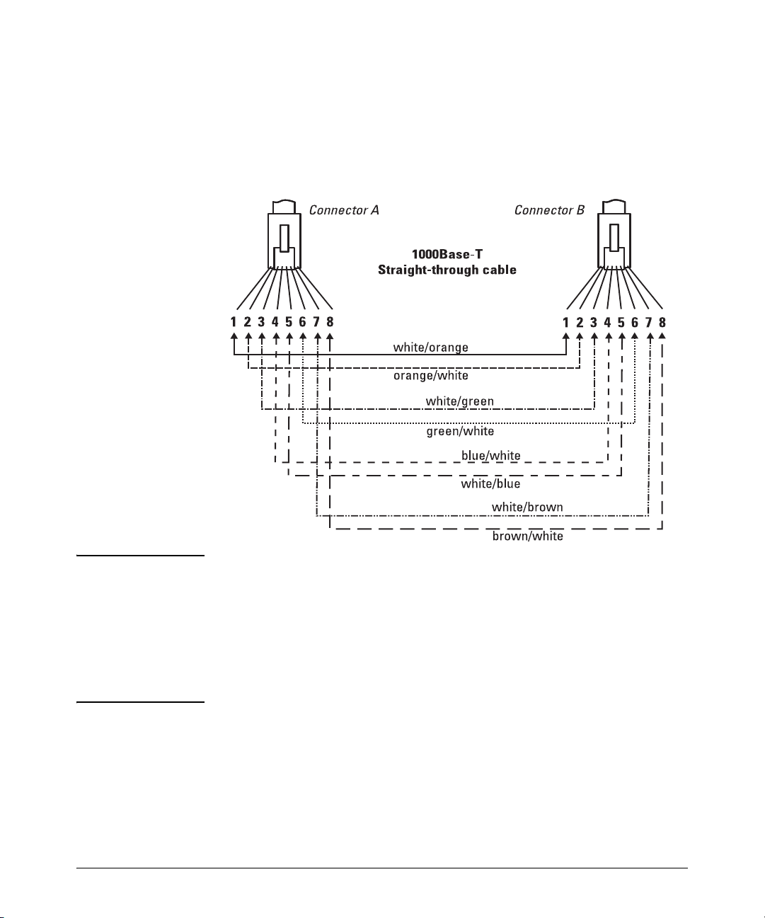
Cabling and Technology Information
Twisted-Pair Cable/Connector Pin-Outs
Straight-Through Twisted-Pair Cable for 1000 Mbps Network Connections
1000Base-T connections require that all four pairs of wires be connected.
Cable Diagram
Note Pins 1 and 2 on connector “A” must be wired as a twisted pair to pins 1 and 2
on connector “B”.
Pins 3 and 6 on connector “A” must be wired as a twisted pair to pins 3 and 6
on connector “B”.
Pins 4 and 5 on connector “A” must be wired as a twisted pair to pins 4 and 5
on connector “B”.
Pins 7 and 8 on connector “A” must be wired as a twisted pair to pins 7 and 8
on connector “B”.
.
Pin Assignments
For 1000Base-T operation, all four pairs of wires are used for both transmit
and receive.
B-8
Page 91

Safety and EMC Regulatory Statements
!
Safety Information
Documentation reference symbol. If the product is marked with this
symbol, refer to the product documentation to get more information
about the product.
C
WARNING A WARNING in the manual denotes a hazard that can cause injury
Caution A Caution in the manual denotes a hazard that can damage equip-
Grounding
These are safety class I products and have protective earthing terminals. There
must be an uninterruptible safety earth ground from the main power source
to the product's input wiring terminals, power cord, or supplied power cord
set. Whenever it is likely that the protection has been impaired, disconnect
the power cord until the ground has been restored.
For LAN cable grounding:
■ If your LAN covers an area served by more than one power distribu-
tion system, be sure their safety grounds are securely interconnected.
■ LAN cables may occasionally be subject to hazardous transient volt-
ages (such as lightning or disturbances in the electrical utilities power
grid). Handle exposed metal components of the network with caution.
Servicing
There are no user-serviceable parts inside these products. Any servicing,
adjustment, maintenance, or repair must be performed only by service-trained
personnel.
or death.
ment.
Do not proceed beyond a WARNING or Caution notice until you
have understood the hazardous conditions and have taken appropriate steps.
These products do not have a power switch; they are powered on when the
power cord is plugged in.
C-1
Page 92

Safety and EMC Regulatory Statements
!
Informations concernant la sécurité
Informations concernant la sécurité
Symbole de référence à la documentation. Si le produit est marqué de
ce symbole, reportez-vous à la documentation du produit afin d'obtenir
des informations plus détaillées.
WARNING Dans la documentation, un WARNING indique un danger susceptible
Caution Un texte de mise en garde intitulé Caution indique un danger suscep-
Cet appareil est un produit de classe I et possède une borne de mise à la terre. La source
d'alimentation principale doit être munie d'une prise de terre de sécurité installée aux
bornes du câblage d'entrée, sur le cordon d'alimentation ou le cordon de raccordement
fourni avec le produit. Lorsque cette protection semble avoir été endommagée,
débrancher le cordon d'alimentation jusqu'à ce que la mise à la terre ait été réparée.
Mise à la terre du câble de réseau local:
■ si votre réseau local s'étend sur une zone desservie par plus d'un système de
distribution de puissance, assurez-vous que les prises de terre de sécurité
soient convenablement interconnectées.
■ Les câbles de réseaux locaux peuvent occasionnellement être soumis à des
surtensions transitoires dangereuses (telles que la foudre ou des perturbations dans le réseau d'alimentation public). Manipulez les composants
métalliques du réseau avec précautions.
Aucune pièce contenue à l'intérieur de ce produit ne peut être réparée par l'utilisateur.
Tout dépannage, réglage, entretien ou réparation devra être confié exclusivement à un
personnel qualifié.
d'entraîner des dommages corporels ou la mort.
tible de causer des dommages à l'équipement.
Ne continuez pas au-delà d'une rubrique WARNING ou Caution avant
d'avoir bien compris les conditions présentant un danger et pris les
mesures appropriées.
Cet appareil ne comporte pas de commutateur principal; la mise sous tension est
effectuée par branchement du cordon d'alimentation.
C-2
Page 93

Hinweise zur Sicherheit
!
Symbol für Dokumentationsverweis. Wenn das Produkt mit diesem
Symbol markiert ist, schlagen Sie bitte in der Produktdokumentation
nach, um mehr Informationen über das Produkt zu erhalten.
Safety and EMC Regulatory Statements
Hinweise zur Sicherheit
WARNING Eine WARNING in der Dokumentation symbolisiert eine Gefahr, die
Caution Caution in der Dokumentation symbolisiert eine Gefahr, die dis Gerät
Dies ist ein Gerät der Sicherheitsklasse I und verfügt über einen schützenden Erdungsterminal. Der Betrieb des Geräts erfordert eine ununterbrochene Sicherheitserdung
von der Hauptstromquelle zu den Geräteingabeterminals, den Netzkabeln oder dem
mit Strom belieferten Netzkabelsatz voraus. Sobald Grund zur Annahme besteht, daß
der Schutz beeinträchtigt worden ist, das Netzkabel aus der Wandsteckdose
herausziehen, bis die Erdung wiederhergestellt ist.
Für LAN-Kabelerdung:
■ Wenn Ihr LAN ein Gebiet umfaßt, das von mehr als einem Stromverteilungs-
system beliefert wird, müssen Sie sich vergewissern, daß die
Sicherheitserdungen fest untereinander verbunden sind.
■ LAN-Kabel können gelegentlich gefährlichen Übergangsspannungen ausge-
setzt werden (beispielsweise durch Blitz oder Störungen in dem
Starkstromnetz des Elektrizitätswerks). Bei der Handhabung exponierter
Metallbestandteile des Netzwerkes Vorsicht walten lassen.
Dieses Gerät enthält innen keine durch den Benutzer zu wartenden Teile. Wartungs-,
Anpassungs-, Instandhaltungs- oder Reparaturarbeiten dürfen nur von geschultem
Bedienungspersonal durchgeführt werden.
Verletzungen oder sogar Todesfälle verursachen kann.
beschädigen kann.
Fahren Sie nach dem Hinweis WARNING oder Caution erst fort,
nachdem Sie den Gefahrenzustand verstanden und die entsprechenden Maßnahmen ergriffen haben.
Dieses Gerät hat keinen Netzschalter; es wird beim Anschließen des Netzkabels
eingeschaltet.
C-3
Page 94

Safety and EMC Regulatory Statements
!
Considerazioni sulla sicurezza
Considerazioni sulla sicurezza
Simbolo di riferimento alla documentazione. Se il prodotto è
contrassegnato da questo simbolo, fare riferimento alla documentazione sul prodotto per ulteriori informazioni su di esso.
WARNING La dicitura WARNINGdenota un pericolo che può causare lesioni o
Caution La dicituraCaution denota un pericolo che può danneggiare le attr-
Questo prodotto è omologato nella classe di sicurezza I ed ha un terminale protettivo
di collegamento a terra. Dev'essere installato un collegamento a terra di sicurezza, non
interrompibile che vada dalla fonte d'alimentazione principale ai terminali d'entrata,
al cavo d'alimentazione oppure al set cavo d'alimentazione fornito con il prodotto.
Ogniqualvolta vi sia probabilità di danneggiamento della protezione, disinserite il cavo
d'alimentazione fino a quando il collegaento a terra non sia stato ripristinato.
Per la messa a terra dei cavi LAN:
■ se la vostra LAN copre un'area servita da più di un sistema di distribuzione
elettrica, accertatevi che i collegamenti a terra di sicurezza siano ben collegati
fra loro;
■ i cavi LAN possono occasionalmente andare soggetti a pericolose tensioni
transitorie (ad esempio, provocate da lampi o disturbi nella griglia d'alimentazione della società elettrica); siate cauti nel toccare parti esposte in metallo
della rete.
Nessun componente di questo prodotto può essere riparato dall'utente. Qualsiasi
lavoro di riparazione, messa a punto, manutenzione o assistenza va effettuato esclusivamente da personale specializzato.
morte.
ezzature.
Non procedere oltre un avviso di WARNING o di Cautionprima di aver
compreso le condizioni di rischio e aver provveduto alle misure del
caso.
Questo apparato non possiede un commutatore principale; si mette scotto tensione
all'inserirsi il cavo d'alimentazione.
C-4
Page 95

Safety and EMC Regulatory Statements
!
Consideraciones sobre seguridad
Consideraciones sobre seguridad
Símbolo de referencia a la documentación. Si el producto va
marcado con este símbolo, consultar la documentación del
producto a fin de obtener mayor información sobre el producto.
WARNING Una WARNING en la documentación señala un riesgo que podría
Caution Una Caution en la documentación señala un riesgo que podría
Este aparato se enmarca dentro de la clase I de seguridad y se encuentra protegido por
una borna de puesta a tierra. Es preciso que exista una puesta a tierra continua desde
la toma de alimentación eléctrica hasta las bornas de los cables de entrada del aparato,
el cable de alimentación o el juego de cable de alimentación suministrado. Si existe la
probabilidad de que la protección a tierra haya sufrido desperfectos, desenchufar el
cable de alimentación hasta haberse subsanado el problema.
Puesta a tierra del cable de la red local (LAN):
■ Si la LAN abarca un área cuyo suministro eléctrico proviene de más de una
red de distribución de electricidad, cerciorarse de que las puestas a tierra
estén conectadas entre sí de modo seguro.
■ Es posible que los cables de la LAN se vean sometidos de vez en cuando a
voltajes momentáneos que entrañen peligro (rayos o alteraciones en la red
de energía eléctrica). Manejar con precaución los componentes de metal de
la LAN que estén al descubierto.
Este aparato no contiene pieza alguna susceptible de reparación por parte del usuario.
Todas las reparaciones, ajustes o servicio de mantenimiento debe realizarlos solamente el técnico.
resultar en lesiones o la muerte.
resultar en averías al equipo.
No proseguir después de un símbolo de WARNING o Caution hasta
no haber entendido las condiciones peligrosas y haber tomado las
medidas apropiadas.
Este producto no tiene interruptor de potencia; se activa cuando se enchufa el cable
de alimentación.
C-5
Page 96

Safety and EMC Regulatory Statements
!
Informações de Segurança
Informações de Segurança
AVISO Um AVISO no manual indica um perigo que possa causar ferimentos
Símbolo de referência à documentação. Se o produto estiver
marcado com este símbolo, consulte a documentação do produto
para obter mais informações sobre ele.
ou morte.
Cuidado Um Cuidado no manual indica um perigo que possa danificar o
Aterramento
Estes são produtos de classe de segurança I, e contam com terminais de
aterramento protetores. É preciso haver um aterramento de segurança ininterrupto da principal fonte de energia até os terminais de ligação de entrada,
o cabo de alimentação ou o conjunto de cabo de alimentação do produto.
Sempre que parecer provável que a proteção tenha sido danificada, desconecte o cabo de alimentação até que o aterramento seja restaurado.
Para aterramento de cabo de LAN:
■ Caso sua LAN cubra uma área servida por mais de um sistema de
distribuição de energia, certifique-se de que os aterramentos de segurança
deles estejam interconectados com segurança.
■ Os cabos de LAN podem ocasionalmente estar sujeitos a tensões tran-
sitórias perigosas (como raios ou perturbações na rede de energia). Tenha
cuidado ao manipular componentes metálicos da rede.
Manutenção
Não há peças internas que possam sofrer manutenção pelo usuário nestes
produtos. Qualquer manutenção, ajuste ou reparo deve ser realizado apenas
por pessoal treinado.
equipamento.
Não passe por um AVISO ou uma indicação de Cuidado sem entender
as condições de perigo e tomar as atitudes apropriadas.
Estes produtos não têm um botão liga/desliga; eles são ativados quando o cabo
de alimentação é conectado.
C-6
Page 97

Safety and EMC Regulatory Statements
Safety Information (Japan)
Safety Information (Japan)
Japan Power
Cord Warning
C-7
Page 98

Safety and EMC Regulatory Statements
Safety Information (China)
Safety Information (China)
C-8
Page 99

Safety and EMC Regulatory Statements
EMC Regulatory Statements
EMC Regulatory Statements
U.S.A.
FCC Class A
This equipment has been tested and found to comply with the limits for a Class
A digital device, pursuant to Part 15 of the FCC Rules. These limits are
designed to provide reasonable protection against interference when the
equipment is operated in a commercial environment. This equipment generates, uses, and can radiate radio frequency energy and, if not installed and
used in accordance with the instruction manual, may cause interference to
radio communications. Operation of this equipment in a residential area may
cause interference in which case the user will be required to correct the
interference at his own expense.
Canada
This product complies with Class A Canadian EMC requirements.
Australia/New Zealand
This product complies with Australia/New Zealand EMC Class A
requirements.
Japan
VCCI Class A
C-9
Page 100

Safety and EMC Regulatory Statements
EMC Regulatory Statements
Korea
Taiwan
C-10
 Loading...