

Page 1

Aruba 2540 Switches
Installation and Getting Started Guide
Abstract
This document contains information on installing the Aruba 2540 switches and performing initial switch configuration.
Part Number: 5200-2084
Published: October 2016
Edition: 1
Page 2

© Copyright 2016 Hewlett Packard Enterprise Development LP
The information contained herein is subject to change without notice. The only warranties for Hewlett Packard Enterprise products and services
are set forth in the express warranty statements accompanying such products and services. Nothing herein should be construed as constituting an
additional warranty. Hewlett Packard Enterprise shall not be liable for technical or editorial errors or omissions contained herein.
Links to third-party websites take you outside the Hewlett Packard Enterprise website. Hewlett Packard Enterprise has no control over and is not
responsible for information outside the Hewlett Packard Enterprise website.
Confidential computer software. Valid license from Hewlett Packard Enterprise required for possession, use, or copying. Consistent with FAR
12.211 and 12.212, Commercial Computer Software, Computer Software Documentation, and Technical Data for Commercial Items are licensed
to the U.S. Government under vendor's standard commercial license.
Acknowledgments
Microsoft® and Windows® are trademarks of the Microsoft group of companies.
Applicable Products
Aruba 2540 24G 4SFP+ Switch JL354A
Aruba 2540 48G 4SFP+ Switch JL355A
Aruba 2540 24G PoE+ 4SFP+ Switch JL356A
Aruba 2540 48G PoE+ 4SFP+ Switch JL357A
Hewlett Packard Enterprise
3000 Hanover Street
Palo Alto, CA 94304
http://www.hpe.com/networking
Page 3

Contents
1 Introducing the 2540 switches ............................................................................... 6
Front of the switches ................................................................................................................................ 6
Network ports ..................................................................................................................................... 7
Management ports ............................................................................................................................. 8
Console Ports .............................................................................................................................. 8
Switch and port LEDs on the front of the switches ............................................................................ 8
LED Mode select button and indicator LEDs ................................................................................... 11
Reset and Clear buttons .................................................................................................................. 12
Back of the switches .............................................................................................................................. 12
Power connector .............................................................................................................................. 13
Switch features ...................................................................................................................................... 13
2 Installing the switch .............................................................................................15
Included parts ........................................................................................................................................ 15
Installation procedures ........................................................................................................................... 16
Summary .......................................................................................................................................... 16
Installation precautions ................................................................................................................... 17
1. Prepare the installation site ............................................................................................................... 17
2. Verify the switch passes self test ....................................................................................................... 18
LED Behavior ................................................................................................................................... 19
3. Mount the switch ................................................................................................................................ 19
Mounting an Aruba 2540 switch ....................................................................................................... 19
Rack mount option: .................................................................................................................... 19
Horizontal surface mount option: ...............................................................................................21
4. Installing or removing SFP/SFP+ transceivers .................................................................................. 21
Installing transceivers: ..................................................................................................................... 22
Removing transceivers: ................................................................................................................... 22
5. Connect the switch to a power source ............................................................................................... 22
6. (Optional) Connect a management console ...................................................................................... 23
Terminal configuration ..................................................................................................................... 24
Direct console access ...................................................................................................................... 24
Console cable pinouts ...................................................................................................................... 25
7. Connect the network cables .............................................................................................................. 26
Using the RJ-45 connectors ............................................................................................................. 26
Connecting cables to SFP/SFP+ transceivers ................................................................................. 26
Sample network topologies .................................................................................................................... 28
As a desktop switch implementing PoE ...........................................................................................28
As a segment switch implementing PoE .......................................................................................... 29
3 Getting started with switch configuration .............................................................30
Recommended minimal configuration ................................................................................................... 30
Using the console setup screen ....................................................................................................... 30
Where to go from here ..................................................................................................................... 32
Software updates ....................................................................................................................... 32
To recover from a lost manager password: ............................................................................... 32
Using the IP address for remote switch management ........................................................................... 32
Starting a Telnet session ................................................................................................................. 32
Starting a web browser session ....................................................................................................... 33
4 Troubleshooting ..................................................................................................34
Basic troubleshooting tips ...................................................................................................................... 34
Diagnosing with the LEDs ...................................................................................................................... 35
LED patterns for general switch troubleshooting ............................................................................. 35
Contents 3
Page 4

Diagnostic tips: ........................................................................................................................... 36
LED patterns for PoE troubleshooting ............................................................................................. 37
Diagnostic Tips: ......................................................................................................................... 38
Proactive networking ............................................................................................................................. 38
Hardware diagnostic tests ..................................................................................................................... 38
Testing the switch by resetting it ...................................................................................................... 38
Checking the switch LEDs ............................................................................................................... 39
Checking console messages ........................................................................................................... 39
Testing twisted-pair cabling ............................................................................................................. 39
Testing switch-to-device network communications .......................................................................... 39
Testing end-to-end network communications .................................................................................. 39
Restoring the factory default configuration ............................................................................................ 39
Downloading new switch software ......................................................................................................... 40
Hewlett Packard Enterprise Customer Support Services ...................................................................... 40
5 Specifications ......................................................................................................41
Switch specifications .............................................................................................................................. 41
Physical ............................................................................................................................................ 41
Electrical .......................................................................................................................................... 41
Environmental .................................................................................................................................. 41
Acoustics .......................................................................................................................................... 41
Safety ............................................................................................................................................... 42
EMC ................................................................................................................................................. 42
Standards .............................................................................................................................................. 42
6 Cabling and technology information .................................................................... 43
Cabling specifications ............................................................................................................................ 43
Technology distance specifications ....................................................................................................... 44
Mode conditioning patch cord ................................................................................................................ 44
Installing the patch cord ................................................................................................................... 45
Twisted-pair cable/connector pinouts .................................................................................................... 45
The Auto-MDIX feature: ................................................................................................................... 45
Other wiring rules: ............................................................................................................................ 46
Straight-through twisted-pair cable for 10 Mbps or 100 Mbps network connections ....................... 46
Cable diagram ............................................................................................................................ 46
Pin assignments ......................................................................................................................... 47
Crossover twisted-pair cable for 10 Mbps or 100 Mbps network connection ................................... 47
Cable diagram ............................................................................................................................ 47
Pin assignments ......................................................................................................................... 47
Straight-through twisted-pair cable for 1000 Mbps network connections ........................................ 47
Cable diagram ............................................................................................................................ 48
Pin assignments ......................................................................................................................... 48
7 Support and other resources ...............................................................................49
Accessing Hewlett Packard Enterprise support ..................................................................................... 49
Before calling support ............................................................................................................................ 49
Accessing updates ................................................................................................................................. 49
Websites ................................................................................................................................................ 50
Customer self repair .............................................................................................................................. 50
Remote support ..................................................................................................................................... 50
Documentation feedback ....................................................................................................................... 51
8 Warranty and regulatory information ................................................................... 52
Warranty information ............................................................................................................................. 52
Regulatory information ........................................................................................................................... 52
Turkey RoHS material content declaration ...................................................................................... 52
Ukraine RoHS material content declaration ..................................................................................... 52
4Contents
Page 5

Index .....................................................................................................................53
Contents 5
Page 6
1 Introducing the 2540 switches
1
2
3
4
The Aruba 2540 are multiport switches that can be used to build high-performance switched
networks. These switches are store-and-forward devices offering low latency for high-speed
networking. The 2540 switches also support Power over Ethernet (PoE/PoE+) technologies and
full network management capabilities.
These switches are described in this manual:
Non-PoE switches PoE+ switches
Aruba 2540 24G 4SFP+ Switch (JL354A) Aruba 2540 24G PoE+ 4SFP+ Switch (JL356A)
Aruba 2540 48G 4SFP+ Switch (JL355A) Aruba 2540 48G PoE+ 4SFP+ Switch (JL357A)
This chapter describes these switches with the following information:
• Front of the switches:
◦ Network ports
◦ Management ports
◦ LEDs
◦ Buttons
• Back of the switches:
◦ Power connectors
• Switch features
Front of the switches
Figure 1 Front of all the 2540 switches
6 Introducing the 2540 switches
Table 1 Front of all the 2540 switches
Label Description
1 Aruba 2540 24G 4SFP+ Switch (JL354A)
2 Aruba 2540 48G 4SFP+ Switch (JL355A)
Page 7
Table 1 Front of all the 2540 switches (continued)
1
5
3
4
6
7
8
9
2
Label Description
3 Aruba 2540 24G PoE+ 4SFP+ Switch (JL356A)
4 Aruba 2540 48G PoE+ 4SFP+ Switch (JL357A)
Figure 2 Example of the Front of the 2540 switches labels and descriptions
Table 2 Front of the 2540 switches labels and descriptions
Label Description
1SFP+ ports
2 SFP+ port LEDs
3 10/100/1000Base-T RJ-45 ports
* PoE Mode LED is present only on switch models that support PoE.
Network ports
Table 3 Network ports
Product
number
JL354A Aruba 2540 24G 4SFP+ Switch 24 4
JL355A Aruba 2540 48G 4SFP+ Switch 48
JL356A Aruba 2540 24G PoE+ 4SFP+ Switch 24 4
JL357A Aruba 2540 48G PoE+ 4SFP+ Switch 48 4
4 Switch port LEDs
5 Global Status, Unit Identification, Speed, PoE*, Usr LEDs
6 RJ Serial Console
7 LED Mode button
8 Reset, Clear buttons
9 Micro USB Console
10/100/1000
PoE/PoE+
1
RJ-45 ports
1
Model name
10/100/1000
non-PoE
RJ-45 ports
SFP+ ports
4
2
Notes:
1
All RJ-45 ports support “Auto-MDIX”, which means you can use either straight-through or crossover
twisted-pair cables to connect network devices to the switch.
2
SFP+ ports support 100Mb (100-FX), 1G SFP, and 10G SFP+ transceivers.
Front of the switches 7
Page 8
These products also support optional network connectivity:
Table 4 Optional network connectivity, speeds and technologies
Speed Technology Cabling
100 Mbps
1000 Mbps
10 Gbps
100-FX Fiber
1000-T Copper
1000-SX Fiber
1000-LX Fiber (multimode
1000-LH Fiber
1000-BX Fiber
10-Gig
Direct Attach
10-Gig SR Fiber
10-Gig LR Fiber
(multimode)
(twisted-pair)
(multimode)
or single mode)
(single mode)
(single mode)
Copper
(twinaxial)
(multimode)
(single mode)
Transceiver form-factor and
connector
SFP
("mini-GBIC")
Connector
LC
RJ-45
LC
LC
LC
LC
1
SFP+ connector
Not applicable
LC
LC
1
For supported transceivers, visit http://www.hpe.com/networking/support.
• In the first textbox, type J4858 (for 100-Mb and Gigabit information), or J8436 (for 10-Gigabit
information).
• Select any of the products that display in the dropdown list and click on Show Selected Items.
•Select Support Center. Then click on Manuals, followed by View All to find the Transceiver
Support Matrix.
For technical details of cabling and technologies, see “Cabling and technology
information” (page 43).
Management ports
Console Ports
There are two serial console port options on the switch, an RJ-45 or Micro USB. These ports are
used to connect a console to the switch either by using the RJ-45 serial cable supplied with the
switch, or a standard Micro USB cable (not supplied). The Micro USB connector has precedence
for input. If both cables are plugged in, the console output is echoed to both the RJ-45 and the
Micro-USB ports, but the input is only accepted from the Micro-USB port.
For more information on the console connection, see “6. (Optional) Connect a management
console” (page 23). The console can be a PC or workstation running a VT-100 terminal emulator,
or a VT-100 terminal.
10-Gig ER Fiber
(single mode)
LC
Switch and port LEDs on the front of the switches
• Table 5 (page 9) describes the switch chassis LEDs and also the Switch Mode LEDs.
• Table 6 (page 9) describes the switch Port LEDs and their different mode behaviors.
8 Introducing the 2540 switches
Page 9
Figure 3 Chassis LEDs for the 2540 switches
1
2
3
4
5
7
6
Table 5 Switch chassis LEDs
Label Description
1 Switch port LEDs
2 Global status LED
3 Unit identification LED
4 Speed LED
5 PoE LED*
6 LED Mode button
7 Usr LED
* PoE Mode LED is present only on switch models that support PoE.
Table 6 Front of switch status and mode LED behavior
Switch LEDs Function State Meaning
Global Status Internal power status of the
switch.
Self-test status
Switch/port fault status
On green The switch has passed self-
test and is powered up
normally.
Slow flash green* The switch self-test and
initialization are in progress
after the switch has been
power cycled or reset. The
switch is not operational until
this LED stops blinking
green.
Slow flash orange* A fault or self-test failure has
occurred on the switch, one
of the switch ports, or a fan.
The Status LED for the
component with the fault will
flash simultaneously.
On orange If this LED is on orange for a
prolonged time, the switch
has encountered a fatal
hardware failure, or has
failed its self-test.
Off The unit is not receiving
power.
Front of the switches 9
Page 10

Table 6 Front of switch status and mode LED behavior (continued)
Switch LEDs Function State Meaning
UID (Unit Identification) The Unit Identification LED
Speed mode selected Indicates when the port
Power over Ethernet (PoE)
mode selected**
is used to help you to identify
a particular unit in a rack or
collection of products.
LEDs are showing port
speed information.
Indicates when the port
LEDs are showing PoE
status information.
On or slow flash* The "chassislocate"
command allows you to blink
or turn on the LED for a
specified number of minutes
(1-1440). The default is 30
minutes.
Off LED will turn off after the
timeout period has expired.
On Speed mode is selected.
Port LEDs indicate port
speed.
Off Speed mode not selected.
On green PoE Mode is selected. Port
LEDs show PoE information.
On orange PoE mode is selected and a
port also has a PoE error.
The Global Status LED and
the LED corresponding to
the port with the error will be
flashing orange. The rest of
the port LEDs will display
normal PoE status.
Slow flash orange* PoE mode has NOT been
selected and a port has a
PoE error. LED will be
flashing orange
simultaneously with the
Global Status LED and the
LED corresponding to the
port with the error. The rest
of the port LEDs will display
normal PoE status.
Off PoE mode is not selected.
User mode selected This mode is reserved for
future use.
* The slow blink behavior is an on/off cycle once every 1.6 seconds, approximately.
** Applies only to switches that support PoE/PoE+.
On green User mode is selected.
Off User mode not selected.
Table 7 Port LEDs and mode behavior
Switch LEDs Function State/Mode Meaning
Port LEDs To display the information for
the port as selected by the
LED Mode select button.
When transceivers and
SFPs are installed, this LED
is also used to indicate that
the installation has occurred
by going on for two seconds
then off.
Activity/Link Shows port Activity and Link
Speed Shows port speed
PoE*** Shows PoE information.
User Shows user selectable user
status.
This is the DEFAULT. There
is no dedicated mode LED
indicating this mode.
The Mode LED function
should return to this
selection 10 minutes after
the last press of the LED
Mode button.
configuration.
behavior.
10 Introducing the 2540 switches
Page 11

Table 7 Port LEDs and mode behavior (continued)
Switch LEDs Function State/Mode Meaning
Activity/Link mode selected Port LEDs are displaying link
status and network activity
information simultaneously.
Activity/Link mode is the
default mode and is in effect
unless another LED mode
has been selected.
Speed mode selected Port LEDs are displaying the
connection speed at which
each port is operating.
Half-bright green The port is enabled and
receiving a link indication
from the connected device.
Activity flicker green The percentage of time that
the LED is full-bright is
roughly proportional to the
percentage of full-bandwidth
utilization of the port.
Half-bright green port link
indication remains on as
activity flickers from halfbright to full-bright.
Slow Flash Orange* The corresponding port has
failed its self-test. Flashes
simultaneously with the
Global Status LED flashing
orange.
Off The port is disabled, not
connected, or not receiving a
link.
On Green The port is operating at
10 Gbps.
Slow Flash Green* The port is operating at
1Gbps.
Off The port is not Linked, or is
operating at 10 or 100 Mbps.
PoE mode selected*** Port LEDs are displaying
PoE information.
* The slow blink behavior is an on/off cycle once every 1.6 seconds, approximately.
** The fast blink behavior is an on/off cycle once every 0.8 seconds, approximately.
*** Applies only to switches that support PoE/PoE+.
LED Mode select button and indicator LEDs
The state of the Mode LEDs is controlled by the LED Mode select button. The current view mode is
indicated by the Mode LEDs next to the button. Press the button to step from one view mode to the
next. See the LED information in Table 6 (page 9).
On Green The port is providing PoE
power.
On Orange PoE is disabled on the port.
Fast Flash Orange** The port is denied power or
is detecting an external PD
fault.
Slow Flash Orange* The port has an internal
hardware failure. Flashes
simultaneously with the
Global Status LED flashing
orange.
Off The port is not providing PoE
power.
Front of the switches 11
Page 12
Reset and Clear buttons
2
3
1
The Reset and Clear buttons are recessed from the front panel (to protect them from being pushed
accidentally) and are accessible through small holes on the top of the front panel. Use pointed
objects, such as unbent paper clips, to push them.
The Reset and Clear buttons are used singly or in combination, as follows:
To accomplish this: Do this: This will happen:
Soft Reset Press and release the Reset button The switch operating system is cleared
Hard Reset Press and hold the Reset button for
Delete console and management
access passwords
Turn off UID LED Press Clear button and release within 5
Restore the factory default
configuration
Note: These buttons are provided for your convenience. If you are concerned with switch security, make sure that the
switch is installed in a secure location, such as a locked wiring closet. You can also disable these buttons by using the
front-panel-security command. See the 2540 Management and Configuration Guide for a description of that command.
more than 5 seconds (until all LEDs
turn on), then release.
Press Clear button for more than 5
seconds, but within 15 seconds (in
between 5 - 15 seconds)
seconds (in between 0.5 - 5 seconds)
1. Press Clear and Reset
simultaneously.
2. While continuing to press Clear,
release Reset.
3. When the Global Status LED begins
to fast flash orange (after
approximately 5 seconds), release
Clear.
gracefully (such as data transfer
completion, temporary error conditions
are cleared), then reboots and runs self
tests.
The switch reboots, similar to a power
cycle. A hard reset is used, for
example, when the switch CPU is in an
unknown state or not responding.
Clears all passwords. Will flash Global
Status Green LED, after 5 seconds has
expired to indicate passwords have
cleared.
Clears the UID LED.
The switch removes all configuration
changes, restores the factory default
configuration, and runs self test.
Back of the switches
The back of all the 24-port and 48-port switches are the same.
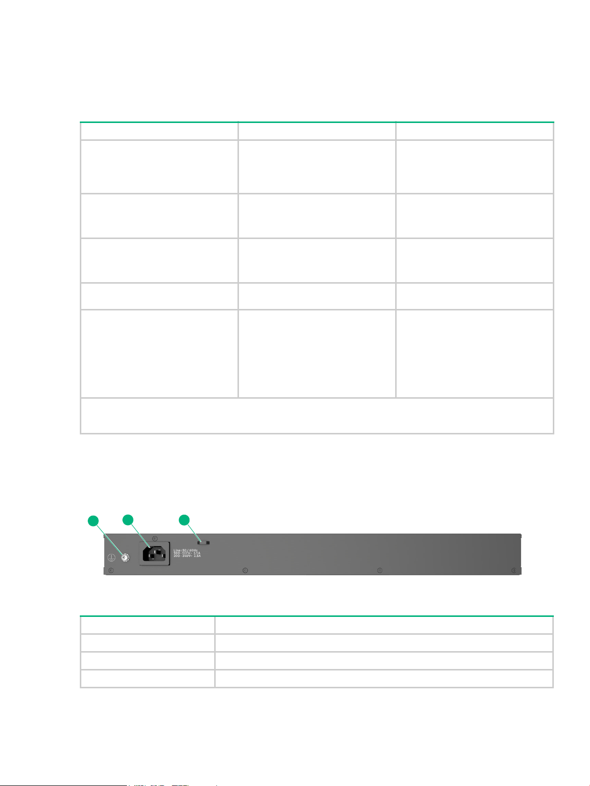
Figure 4 Back of the 2540 switches
Table 8 Back of the 2540 switches labels and descriptions
Label Description
1 Ground point
2 AC power connector
3 Cable tie eyelet
12 Introducing the 2540 switches
Page 13

Power connector
The 2540 switches do not have a power switch; they are powered on when connected to an active
AC power source. The switches automatically adjust to any voltage between 100-127 and 200-240
volts and either 50 or 60 Hz. There are no voltage range settings required.
Switch features
The features of the 2540 Switches include:
• Combinations of fixed 10/100/1000-T and SFP+ ports, as described under “Network
ports” (page 7).
• Power over Ethernet (PoE+) operation (JL356A, JL357A)—The PoE+ switches are IEEE
802.3at standard compliant and provide up to 30W per port to power IP phones, wireless
access points, indoor web cameras, and more. For more information, see the HPE Power over
Ethernet (PoE/PoE+) Planning and Implementation Guide, available from www.hpe.com/
networking/ResourceCenter.
The switches support 802.3af and 802.3at standard devices and some pre-standard PoE
devices. For a list of these devices, see the FAQs (Frequently Asked Questions) for your switch
model. PoE is enabled by default. (For more information, see the 2540 Management and
Configuration Guide for your switch at www.hpe.com/networking/ResourceCenter
• Plug-and-play networking. All ports are enabled by default, just connect the network cables to
active network devices and your switched network is operational.
.
• Auto MDI/MDI-X on all twisted-pair ports (10/100/1000Base-T), meaning that all connections
can be made using straight-through twisted-pair cables. Cross-over cables are not required,
although they will also work. The pin operation of each port is automatically adjusted for the
attached device: if the switch detects that another switch or hub is connected to the port, it
configures the port as MDI; if the switch detects that an end-node device is connected to the
port, it configures the port as MDI-X. (See “Cabling and technology information” (page 43) for
recommended or required cabling.)
• Automatic learning of the network addresses in each switch’s 64000-address forwarding table
(with configurable address aging value).
• Automatically negotiated full-duplex operation for the 10/100/1000 RJ-45 ports when
connected to other auto-negotiating devices. The SFP+ ports always operate at full duplex.
• Easy management of the switch through several available interfaces:
◦ Console interface—A full featured, easy to use, VT-100 terminal interface for out-of-band
or in-band switch management.
◦ Web browser interface—An easy to use built-in graphical interface that can be accessed
from common web browsers.
◦ Aruba AirWave—A powerful and easy-to-use network operations system that manages
wired and wireless infrastructures. For more information, go to www.arubanetworks.com/
products/networking/management/airwave.
◦ IMC (Intelligent Management Center)—An SNMP-based, graphical network management
tool that you can use to manage your entire network. Free trials of IMC can be downloaded
at http://www.hpe.com/networking/imc
.
• Support for the Spanning Tree Protocol to eliminate network loops.
• Support for up to 4096 IEEE 802.1Q-compliant VLANs so you can divide the attached end
nodes into logical groupings that fit your business needs.
• Support for many advanced features to enhance network performance. For a description, see
the 2540 Management and Configuration Guide at www.hpe.com/networking/ResourceCenter
Switch features 13
.
Page 14

• To download product updates, go to either of the following:
◦ Hewlett Packard Enterprise Support Center Get connected with updates page:
www.hpe.com/support/e-updates
◦ HPE Networking Software: www.hpe.com/networking/software
◦ To view and update your entitlements, and to link your contracts and warranties with your
profile, go to the Hewlett Packard Enterprise Support Center More Information on Access
to Support Materials page: www.hpe.com/support/AccessToSupportMaterials
• Low power operation:
◦ Ports on a switch may be set to operate at reduced power.
◦ Port status LEDs may be turned off.
◦ RJ-45 ports operate at reduced power if they are not connected (link partner is not
detected).
14 Introducing the 2540 switches
Page 15
2 Installing the switch
This chapter shows how to install the switch. The Aruba 2540 switches come with an accessory kit
that includes the brackets for mounting the switch in a standard 19-inch telco rack, in an equipment
cabinet, and with rubber feet that can be attached so the switch can be securely located on a
horizontal surface. The brackets are designed to allow mounting the switch in a variety of locations
and orientations. For other mounting options contact your local Hewlett Packard Enterprise
authorized network reseller or Hewlett Packard Enterprise representative.
NOTE: If an Aruba 2540 switch is to be shipped in a rack, it can be mounted and shipped in a
Hewlett Packard Enterprise 10K rack using the HPE X410 Universal Rack Mounting Kit (J9583A).
Additionally, it can also be mounted in any four post rack using the HPE X410 Universal Rack
Mounting Kit (J9583A).
Included parts
The 2540 switches have the following components shipped with them:
• Aruba Switch Quick Setup Guide and Safety/Regulatory Information
• Switch Safety and Regulatory sheet
• Warranty notice
• General Safety and Regulatory booklet
• Accessory kits and console cable
Aruba 2540 switch model Part number Count Included items
JL356A 24G PoE+ 4SFP+ Switch
JL357A 48G PoE+ 4SFP+ Switch
JL354A 24G 4SFP+ Switch
JL355A 48G 4SFP+ Switch
All Aruba 2540 switch models 5188-3836 1 Console cable
5092-0727 2
5092-0769
Rack mount brackets
4
Rubber foot pads
1
Cable tie
8
Small screws; bracket-to-switch
4
Large screws; bracket-to-rack
• There are two warranty documents. One is the HPN warranty and the other is the EG warranty.
◦ 5998-5984 Warranty Statement and Software License
◦ 703828-025 EG Safety, Compliance, and Warranty Information
• Power cord, one of the following
Argentina 8121–0729 Israel 8121–1004
Australia/New Zealand 8121-0837 Japan 8121–1143
Brazil 8121-1071 Switzerland 8121–0738
Chile 8121–0735 South Africa 8121–0737
China 8121–0943 Taiwan 8121-0964
Continental Europe/South Korea 8121–0731 Philippines/Thailand 8121-0734
Denmark 8121–0733 UK/Hong Kong/Singapore/Malaysia 8121–0739
India 8121–0564 US/Canada/Mexico 8121-1141
Included parts 15
Page 16

Installation procedures
Summary
1. Prepare the installation site (“1. Prepare the installation site” (page 17)). Ensure the physical
environment into which you will be installing the switch is properly prepared, including having
the correct network cabling ready to connect to the switch and having an appropriate location
for the switch. See “Installation precautions” (page 17) for some installation precautions.
2. Verify the switch passes self test (“2. Verify the switch passes self test” (page 18)). Plug the
switch into a power source and observe that the LEDs on the switch’s front panel indicate
correct switch operation. When self test is complete, unplug the switch.
3. Mount the switch (“3. Mount the switch” (page 19)). The switch can be mounted in a 19-inch telco rack, in an equipment cabinet, or on a horizontal surface.
4. (Optional) Install SFP/SFP+ transceivers (“4. Installing or removing SFP/SFP+
transceivers” (page 21)). The switch has two or four slots for installing SFP/SFP+ transceivers.
Depending on where you install the switch, it may be easier to install the transceivers first.
Transceivers can be hot swapped—they can be installed or removed while the switch is
powered on.
5. Connect power to the switch (“5. Connect the switch to a power source” (page 22)). Once the switch is mounted, plug it into the main power source.
6. (Optional) Connect a management console to the switch (“6. (Optional) Connect a
management console” (page 23)). You may want to modify the switch’s configuration, for
example, to configure an IP address so it can be managed using a Web browser, from an
SNMP network management station, or through a Telnet session. Configuration changes can
be made by using the included console cable to connect a PC to the switch’s console port.
7. Connect the network devices (“7. Connect the network cables” (page 26)). Using the appropriate network cables, connect the network devices to the switch ports.
At this point, your switch is fully installed. See the rest of this chapter if you need more detailed
information on any of these installation steps.
16 Installing the switch
Page 17

Installation precautions
WARNING!
• The rack or cabinet should be adequately secured to prevent it from becoming unstable and/
or falling over.
• Devices installed in a rack or cabinet should be mounted as low as possible, with the heaviest
devices at the bottom and progressively lighter devices installed above.
CAUTION:
• When installing the switch, the AC outlet should be near the switch and should be easily
accessible in case the switch must be powered off.
• Ensure the power source circuits are properly grounded, then use the power cord supplied
with the switch to connect it to the power source.
• Use only approved power cords with your Aruba Networking Product. Please see the power
cord information in the section titled “Included parts” (page 15) of this guide for acceptable
power cords that are appropriate for this product. Failure to use approved power cords can
result in personal injury and product damage, and may void your product warranty.
• Use only the AC/DC power adapter and power cord (if applicable), supplied with the switch.
Use of other adapters or power cords, including those that came with other Hewlett Packard
Enterprise products, may result in damage to the equipment.
• If your installation requires a different power cord than the one supplied with the switch and
power supply, be sure the cord is adequately sized for the switch’s current requirements. In
addition, be sure to use a power cord displaying the mark of the safety agency that defines the
regulations for power cords in your country. The mark is your assurance that the power cord
can be used safely with the switch and power supply.
• When installing the switch, the AC outlet should be near the switch and should be easily
accessible in case the switch must be powered off.
• Ensure the switch does not overload the power circuits, wiring, and over-current protection. To
determine the possibility of overloading the supply circuits, add together the ampere ratings of
all devices installed on the same circuit as the switch and compare the total with the rating
limit for the circuit. The maximum ampere ratings are usually printed on the devices near the
AC power connectors.
• Do not install the switch in an environment where the operating ambient temperature might
exceed its specification. This includes a fully-enclosed rack. Ensure the air flow around the
sides and back of the switch is not restricted. Leave at least 3 inches (7.6 cm) for cooling for
the switches when installed in a fully-enclosed rack.
1. Prepare the installation site
Cabling Infrastructure - Ensure the cabling infrastructure meets the necessary network
specifications. See appendix A, “Cabling and technology information” (page 43) for more
information:
Installation Location - Before installing the switch, plan its location and orientation relative to
other devices and equipment:
• In the front of the switch, leave at least 3 inches (7.6 cm) of space for the twisted-pair and fiberoptic cabling.
• In the back of the switch, leave at least 1 1/2 inches (3.8 cm) of space for the power cord.
• On the sides of the switch, leave at least 3 inches (7.6 cm) for cooling.
1. Prepare the installation site 17
Page 18
2. Verify the switch passes self test
1
2
3
4
Before mounting the switch in its network location, you should first verify it is working properly by
plugging it into a power source and verifying it passes its self test.
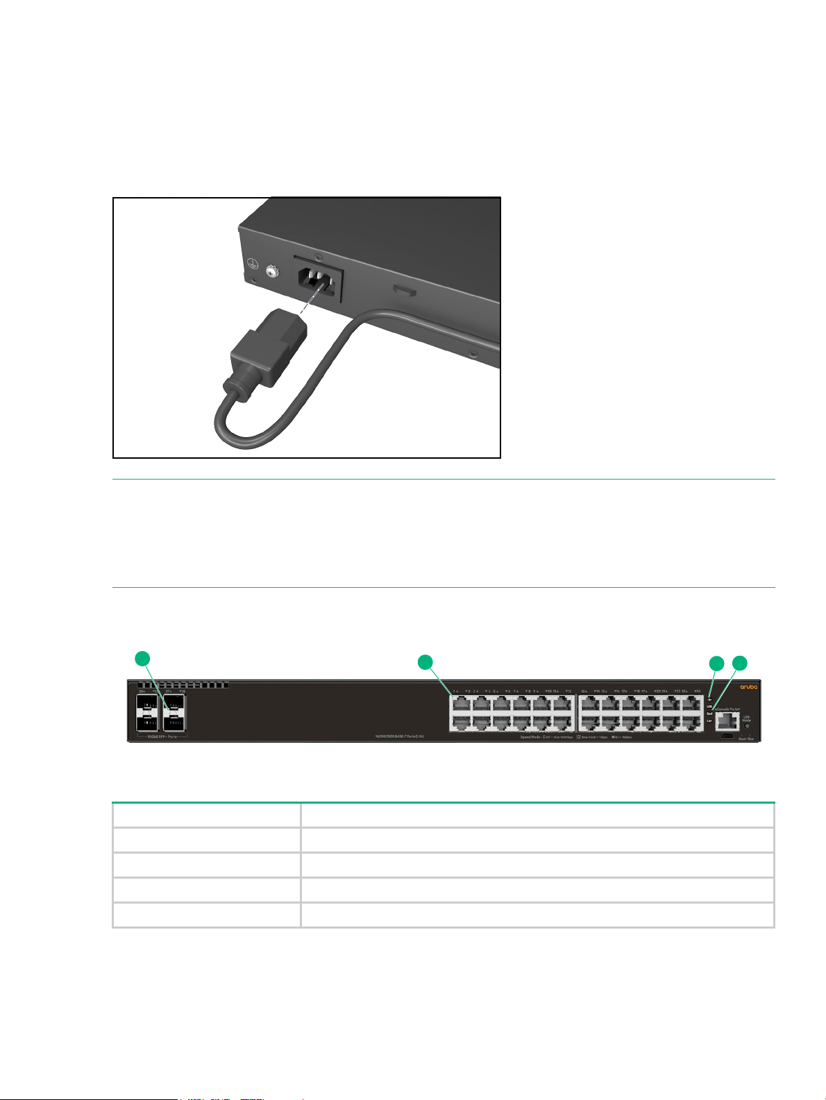
1. Connect the power cord supplied with the switch to the power connector on the back of the switch, and then into a properly grounded electrical outlet.
Figure 5 Connecting the power cord on the Aruba 2540 switches
NOTE: The 2540 switches do not have a power switch. They are powered on when the power
cord is connected to the switch and to a power source. For safety, the power outlet should be
located near the switch installation.
The switch automatically adjusts to any voltage between 100-127 or 200-240 volts and either 50
or 60 Hz. There are no voltage range settings required.
2. Check the LEDs on the switch as described below.
Figure 6 Example of LEDs on the 2540 switches
Table 9 Example of LEDs on the 2540 switches labels and descriptions
Label Description
1 SFP/SFP+ port LEDs
2 RJ-45 port LEDs
3 Global Status and UID LEDs
When the switch is powered on, it performs its diagnostic self test and initialization. This boot
process, depending on switch model and configuration, takes approximately 1-2 minutes to
complete.
18 Installing the switch
4 Mode LEDs
Page 19

LED Behavior
During the switch boot:
• The Global Status, UID, other status and mode LEDs, will initially turn on green and bi-color
LEDs will change to orange, then back to green.
• The Global Status LED will start blinking green, indicating the switch is going through its selftest and will continue to blink green until the switch if fully booted.
• The port LEDs will come on green, turn orange, turn back to green, and then may blink on and
off during phases of the boot.
When the switch boots successfully, the LEDs display as follows:
• Global Status LED will be on solid green.
• UID LED is off.
• Other status LEDs may be on or off depending on the switch configuration and the hardware
installed.
• The port LEDs go into their normal operating mode:
◦ If the ports are connected to active network devices, the port LED may be on and behaves
according to the LED mode selected. In the default LED mode (Activity/Link), the LED
should show half-bright green to indicate Link and be flickering full-bright green to show
network traffic.
◦ If the ports are not connected to active network devices, the port LED will stay off.
If the LED display is different than what is described above, especially if the Global Status LED
continues to blink green for more than 120 seconds or blinks orange continually, then the switch
boot has not completed correctly. Refer to “Troubleshooting” (page 34) for diagnostic help.
3. Mount the switch
Mounting an Aruba 2540 switch
The supported mounting options for the Aruba 2540 switches include:
• Rack mount
• Horizontal surface mount
Rack mount option:
The switch is designed to be mounted in any EIA-standard 19-inch telco rack or communication
equipment cabinet.
The Aruba 2540 switches can also be mounted in 4-post racks and cabinets by using the X410
Switch Rail Kit (J9583A). For instructions on using the kit, see the documentation that is included
with the kit.
NOTE: If an Aruba 2540 switch is to be shipped in a rack, it can be mounted and shipped in a
Hewlett Packard Enterprise 10K rack using the HPE X410 Universal Rack Mounting Kit (J9583A).
Additionally, it can also be mounted in any four post rack using the HPE X410 Universal Rack
Mounting Kit (J9583A).
Some mounting brackets have multiple mounting holes and can be rotated, allowing for a wide
variety of mounting options. Secure the rack in accordance with the manufacture’s safety
guidelines.
3. Mount the switch 19
Page 20
WARNING! For safe operation, please read the mounting precautions in “Installation
precautions” (page 17), before mounting a switch.
EQUIPMENT CABINET NOTE: The 12-24 screws supplied with the switch are the correct
threading for standard EIA/TIA open 19-inch racks. If installing the switch in an equipment cabinet
such as a server cabinet, use the clips and screws that came with the cabinet in place of the 1224 screws that are supplied with the switch.
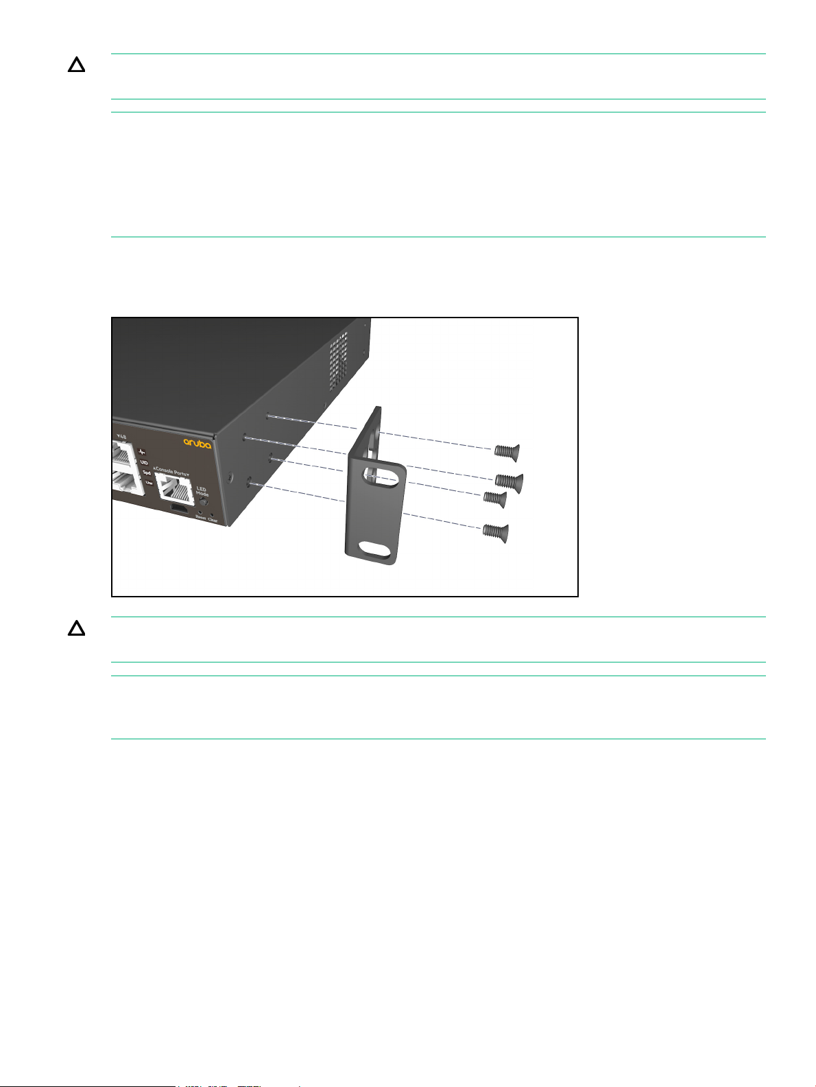
Complete step 1, and plan which four holes you will be using in the cabinet and install all four
clips. Then proceed to step 2.
1. Use a #1 Phillips (cross-head) screwdriver and attach the mounting brackets to the switch with the included 8-mm M4 screws.
Figure 7 Attaching mounting brackets to the 2540 switches
WARNING! For safe reliable installation, only use the screws provided in the accessory kit to
attach the mounting brackets to the switch.
NOTE: The mounting brackets have multiple mounting holes and can be rotated allowing for a
wide variety of mounting options. These include mounting the switch so that its front face is flush
with the face of the rack, or mounting it in a more balanced position.
2. Hold the switch with attached brackets up to the rack and move it vertically until rack holes line up with the bracket holes, then insert and tighten the four number 12-24 screws holding the brackets to the rack.
20 Installing the switch
Page 21
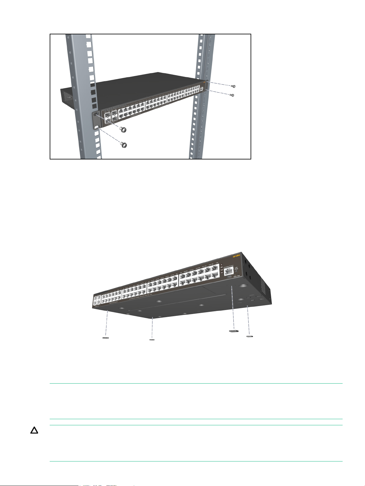
Figure 8 Mounting the 2540 switches in a rack
Horizontal surface mount option:
Place the switch on a table or other horizontal surface. The switch comes with rubber feet in the
accessory kit that can be used to help keep the switch from sliding on the surface.
Attach the rubber feet to the four corners on the bottom of the switch within the embossed angled
lines. Use a sturdy surface in an uncluttered area. You may want to secure the networking cables
and switch power cord to the table leg or other part of the surface structure to help prevent tripping
over the cords.
Figure 9 Mounting the 2540 switches on a horizontal surface
4. Installing or removing SFP/SFP+ transceivers
You can install or remove a transceiver from an SFP+ slot without having to power off the switch.
NOTES:
• The transceivers operate only at full duplex. Half duplex operation is not supported.
• Ensure the network cable is NOT connected when you install or remove a transceiver.
CAUTION: Use only supported genuine HPE Aruba SFP/SFP+ transceivers with your switch.
Non-HPE Aruba SFP/SFP+ transceivers are not supported, and their use may result in product
malfunction. Should you require additional transceivers, contact your HPE Aruba sales
representative or an authorized reseller.
4. Installing or removing SFP/SFP+ transceivers 21
Page 22

Installing transceivers:
Hold the transceiver by its sides and gently insert it into either of the slots on the switch until it
clicks into place. When a transceiver is inserted the switch authenticates it. This can take 1-3
seconds, with the worst case being 5 seconds. If the transceiver is removed before the
authentication completes a self test failure will be reported.
WARNING! The fiber-optic HPE Aruba transceivers are Class 1 laser devices. Avoid direct eye
exposure to the beam coming from the transmit port.
NOTE: Always disconnect the network cable from a transceiver before installing it in the switch.
Figure 10 Installing a transceiver
Removing transceivers:
NOTE: Always disconnect the network cable from the transceiver before removing it from the
switch.
Depending on when the transceiver was purchased, it may have either of three different release
mechanisms: a plastic tab on the bottom of the transceiver, a plastic collar around the transceiver,
or a wire bail.
To remove the transceivers that have the plastic tab or plastic collar, push the tab or collar toward
the switch until the transceiver releases from the switch (it will move outward slightly), then pull it
from the slot.
To remove the transceivers that have the wire bail, lower the bail until it is approximately horizontal,
and then using the bail, pull the transceiver from the slot.
5. Connect the switch to a power source
1. Plug the included power cord into the switch’s power connector and into a nearby AC power source.
22 Installing the switch
Page 23

Figure 11 Connecting the power cord
2. Re-check the LEDs during self test. See “LED Behavior” (page 19).
3. Use the included cable tie to secure the power cord to the switch.
Figure 12 Using the cable tie on the 2540 switches
6. (Optional) Connect a management console
The switches have a full-featured, easy to use console interface for performing switch
management tasks including the following:
• Monitor switch and port status and observe network activity statistics.
• Modify the switch’s configuration to optimize switch performance, enhance network traffic
control, and improve network security.
• Read the event log and access diagnostic tools to help in troubleshooting.
• Download new software to the switch.
• Add passwords to control access to the switch from the console, Web browser interface, and
network management stations.
The console can be accessed through these methods:
• Out-of-band: The switches come with a serial cable for connecting a PC or VT-100 terminal, to
be used as a console, directly to the switch’s RJ-45 Console Port.
6. (Optional) Connect a management console 23
Page 24

There is also the option of using a USB cable (not supplied) to connect the switch’s Micro USB
Console Port to a PC. To use the USB Console Port, you must first download a USB driver to
the PC. See the Note on page 24 for more information.
Note that you cannot use both the RJ-45 Console Port and USB Console Port at the same
time. When the USB Console Port is connected to a live PC, it has priority over the RJ-45
Console Port.
By default, the RJ-45 console port is active (accepts input). To activate the USB console port,
connect it to a live PC. If the USB console session is closed by the inactivity timer, the RJ-45
console port becomes active again to allow remote access via a terminal server. To reactivate
the USB console port, unplug it, then reconnect it to a live PC.
• In-Band: Access the console using Telnet from a PC or UNIX station on the network, and a VT100 terminal emulator. This method requires that you first configure the switch with an IP
address and subnet mask by using either out-of-band console access or through DHCP/Bootp.
For more information on IP addressing and on starting a Telnet session, see chapter 3, “Getting
started with switch configuration” (page 30).
The switches can simultaneously support one out-of-band console session through a Console Port
and in-band Telnet console sessions.
Terminal configuration
To connect a console to the switch, configure the PC terminal emulator as a DEC VT-100 (ANSI)
terminal or use a VT-100 terminal, and configure either one to operate with these settings:
• Any baud rate from 1200 to 115200 (the switch senses the speed).
• 8 data bits, 1 stop bit, no parity, and flow control set to off.
• For the Windows Terminal program, also disable (uncheck) the “Use Function, Arrow, and C
Keys for Windows” option.
• For the Hilgraeve HyperTerminal program, select the “Terminal keys” option for the “Function,
arrow, and ctrl keys act as” parameter.
If you want to operate the console using a different configuration, make sure you change the
settings on both the terminal and on the switch so they are compatible. Change the switch settings
first, then change the terminal settings, then reboot the switch and reestablish the console session.
NOTE: USB Console Port Driver Download. When using the Micro USB Console Port, the
connected PC first requires “virtual COM port” USB drivers to be installed. USB drivers are
available for Windows XP, Windows Vista, and Windows 7.
USB console drivers are available at www.hpe.com/networking/support
(e.g. 2540) or product number in the Auto Search textbox. Select one of the switches from the
drop-down list. Click the Display selected button. From the options that appear, select Software
downloads (on the right-hand side). Download the “USB Console Port Drivers and Information.”
Direct console access
To connect a console to the switch, follow these steps:
trl
. Type a product name
1. Connect the PC or terminal to the switch’s Console Port using the console cable included with
the switch. (If your PC or terminal has a 25-pin serial connector, first attach a 9-pin to 25-pin
straight-through adapter at one end of the console cable.)
Alternatively, connect the PC to the switch’s Micro USB Console Port using a USB cable (not
supplied).
connectors. The maximum allowable length is 5 meters.
24 Installing the switch
Use a USB 2.0 high-speed cable with male type A (4-pin) to male micro-B (5-pin)
Page 25

To use the USB Console Port, you must first download a USB driver to the PC. See the Note on
5 4 3 2 1
9 8 7 6
12345678
page 24 for more information.
Figure 13 Connecting a console cable
2. Turn on the terminal or PC’s power and, if using a PC, start the PC terminal program.
3. Press [Enter] two or three times and you will see the copyright page and the message “Press any key to continue”. Press a key, and you will then see the switch console command (CLI) prompt, for example:
Aruba-2540-24G-4SFPP#
If you want to continue with console management of the switch at this time, see chapter 3, “Getting
started with switch configuration” (page 30) for some basic configuration steps. For more detailed
information, refer to the Basic Operation Guide and the Manangement and Configuration Guide,
which are on the Hewlett Packard Enterprise Web site at www.hpe.com/networking/
ResourceCenter.
Console cable pinouts
The console cable has an RJ-45 plug on one end and a DB-9 female connector on the other end.
Table 10 (page 25) describes the mapping of the RJ-45 to DB-9 pins.
Figure 14 RJ-45 to DB-9 pinouts
Table 10 Mapping of RJ-45 to DB-9
RJ-45 (Signal reference from Chassis) DB-9 (Signal reference from PC)
Reserved 1 8 CTS
Reserved 2 6 DSR
TXD 3 2 RXD
Reserved 4 1 DCD
GND 5 5 GND
RXD 6 3 TXD
Reserved 7 4 DTR
6. (Optional) Connect a management console 25
Page 26

Table 10 Mapping of RJ-45 to DB-9 (Continued)
RJ-45 (Signal reference from Chassis) DB-9 (Signal reference from PC)
Reserved 8 7 RTS
7. Connect the network cables
Connect the network cables, described under “Cabling Infrastructure” (“1. Prepare the installation
site” (page 17)), from the network devices or your patch panels to the fixed RJ-45 ports on the
switch or to any SFPs you have installed in the switch.
Using the RJ-45 connectors
To connect:
Push the RJ-45 plug into the RJ-45 port until the tab on the plug clicks into place. When power is
on for the switch and for the connected device, the Link LED for the port should light to confirm a
powered-on device (for example, an end node) is at the other end of the cable.
If the Link LED does not go on when the network cable is connected to the port, see “Diagnosing
with the LEDs” (page 35) in chapter 4, “Troubleshooting”.
To disconnect:
Press the small tab on the plug and pull the plug out of the port.
9RI
Figure 15 Connecting an RJ-45
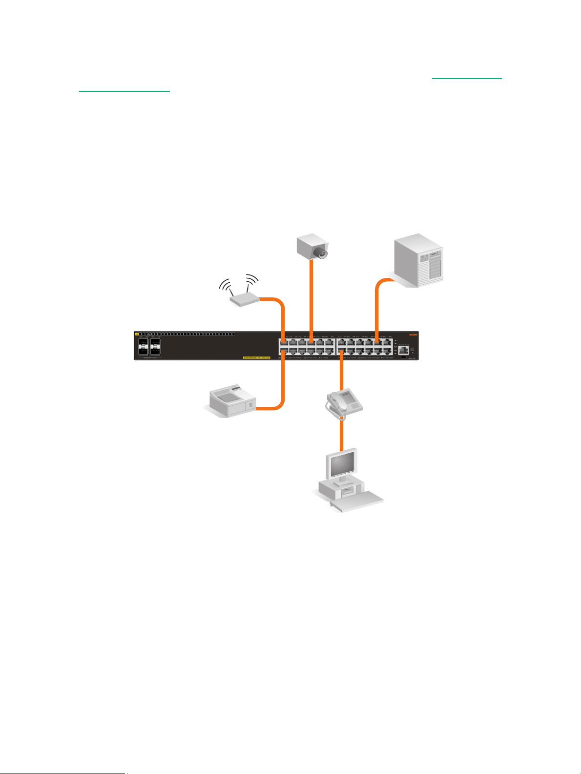
Connecting cables to SFP/SFP+ transceivers
If you have any transceivers installed in the switch, the type of network connections you will need
to use depends on the type of transceivers installed. See chapter 6, “Cabling and technology
information” (page 43), for cabling information.
For transceiver ports, and in general for all the switch ports, a network cable from an active network
device is connected to the port. If the port LED does not come on half-bright when the network
cable is connected to the port, see “Diagnosing with the LEDs” (page 35) in chapter 4,
“Troubleshooting.”
26 Installing the switch
Page 27
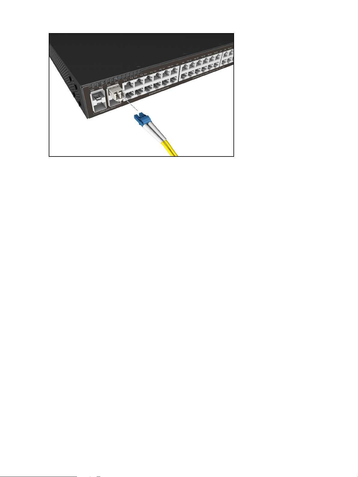
Figure 16 Connecting cable to a transceiver
7. Connect the network cables 27
Page 28
Sample network topologies
This section shows a few sample network topologies in which the Aruba 2540 switches are
implemented. For more topology information, visit the product’s website at www.hpe.com/
networking/support.
As a desktop switch implementing PoE
The switch is designed to be used primarily as a desktop switch to which end nodes, printers and
other peripherals, and servers are directly connected, as shown in the following illustration.
Notice that the end node devices are connected to the switch by straight-through or crossover
twisted-pair cables. Either cable type can be used because of the “IEEE Auto MDI/MDI-X” features
on the switch.
Figure 17 Basic desktop configuration
The above illustration is an example of the switch being configured to supply PoE/PoE+ power to
end devices such as IP telephones and wireless access points (WAPs).
As shown in Figure 17 (page 28), the IP telephones can be connected in line, that is, between the
switch and the end device, in this case a PC. The IP telephones have two ports, one in and one
out. Therefore the phone receives voice and power from the switch and the PC can send and
receive data through the phone to the switch.
The end node devices are connected to the switch by straight-through or crossover twisted-pair
cables. Either cable type can be used because of the Auto-MDIX feature on the switch.
28 Installing the switch
Page 29
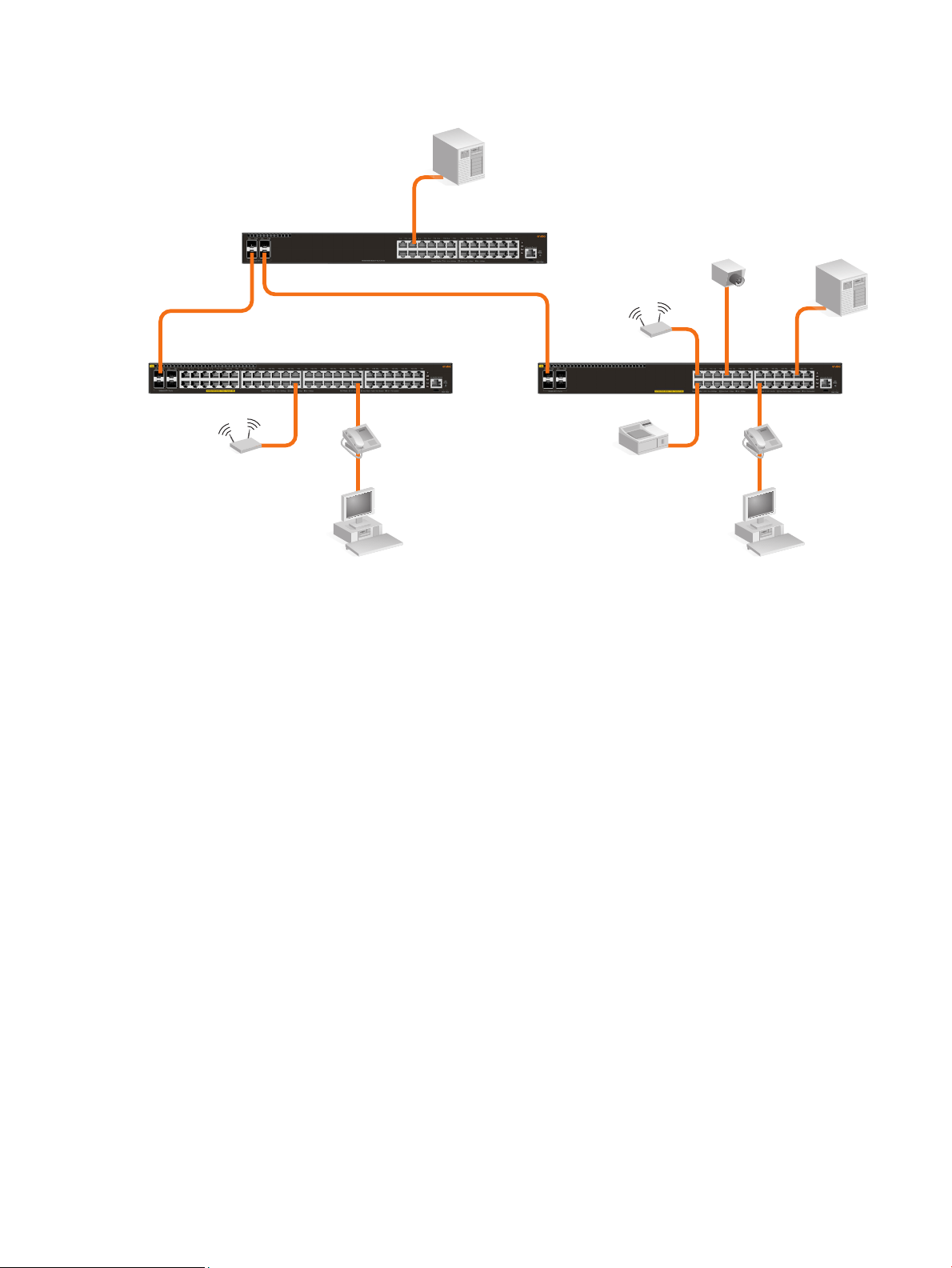
As a segment switch implementing PoE
Figure 18 Segment network configuration with PoE switches
The Aruba 2540 switch also works well as a segment switch. That is, with its high performance, it
can be used for interconnecting network segments—simply connect the network devices that form
those segments to the switch, or you can also connect other switches.
In the illustration above, two 2540 PoE+ switches with PCs, printers, and local servers attached,
are both connected to a non-PoE switch. The devices attached to the two 2540 PoE+ switches can
now communicate with each other through the non-PoE switch. They can also all communicate
with the server that is connected to a 1000BASE-T port on the switch.
As shown in the illustration above, the IP telephones have been inserted in between the 2540
PoE+ switch and the PCs, and a wireless access point (WAP) has been connected to the 2540
PoE+ switch. Only devices directly connected to PoE switches can receive PoE power. Devices
connected to the non-PoE switch cannot receive PoE power.
Because the 2540 switches have the Auto-MDIX feature, the connections between the switches
and end nodes or servers can be through category 5 straight-through or crossover twisted-pair
cable. Category 3 or 4 cable can also be used if the connection is 10 Mbps only. In all cases, the
device ports must be configured to auto negotiate the link characteristics for this feature to work.
The switch, in turn, can be connected to a network backbone through fiber-optic cabling connected
to a Gigabit or 10 Gigabit transceiver installed in the switch. Now, all the devices on these network
segments can access other network resources that are connected elsewhere on the network
backbone.
Sample network topologies 29
Page 30

3 Getting started with switch configuration
This chapter is a guide for using the console Switch Setup screen to quickly assign an IP (Internet
Protocol) address and subnet mask to the switch, set a Manager password, and, optionally,
configure other basic features.
For more information on using the switch console, see the Basic Operation Guide and the
Management and Configuration Guide for your switch at www.hpe.com/networking/
ResourceCenter. For information on the HPE IMC (Intelligent Management Center), contact your
HPE/Aruba representative. For information on Aruba AirWave, go to www.arubanetworks.com/
products/networking/management/airwave.
Recommended minimal configuration
In the factory default configuration, the switch has no IP (Internet Protocol) address and subnet
mask, and no passwords. In this state, it can be managed only through a direct console
connection. To manage the switch through in-band (networked) access, you should configure the
switch with an IP address and subnet mask compatible with your network.
Also, you should configure a Manager password to control access privileges from the console and
Web browser interface. Other parameters in the Switch Setup screen can be left at their default
settings or you can configure them with values you enter.
Many other features can be configured through the switch’s console interface, to optimize the
switch’s performance, to enhance your control of the network traffic, and to improve network
security. Once an IP address has been configured on the switch, these features can be accessed
more conveniently through a remote Telnet session, through the switch’s Web browser interface,
and from an SNMP network management station running a network management program. For a
listing of switch features available with and without an IP address, refer to “How IP Addressing
Affects Switch Operation” in the Management and Configuration Guide.
For more information on IP addressing, refer to the Basic Operation Guide at www.hpe.com/
networking/ResourceCenter.
NOTE: By default, the switch is configured to acquire an IP address configuration from a DHCP
or Bootp server. To use DHCP/Bootp instead of the manual method described in this chapter, see
“DHCP/Bootp Operation” in the Management and Configuration Guide.
Using the console setup screen
The quickest and easiest way to minimally configure the switch for management and password
protection in your network is to use a direct console connection to the switch, start a console
session, and access the Switch Setup screen.
1. Using the method described in “Terminal configuration” (page 24), connect a terminal device to the switch and display the switch console command line interface (CLI) prompt (the default display).
The CLI prompt appears, for example:
Aruba-2540-24G-4SFPP#
2. At the prompt, enter the setup command to display the Switch Setup screen. The following illustration shows the Setup screen with the default settings.
30 Getting started with switch configuration
Page 31
Figure 19 Example console setup screen
Aruba-2540-24G-PoEP-4SFPP 6-Aug-2016 8:23:16
==========================- CONSOLE - MANAGER MODE -==========================
Switch Setup
System Name : Aruba-2540-24G-4SFPP
System Contact :
Manager Password : ****************
Confirm Password : ****************
Logon Default : CLI Time Zone [0] : 0
Community Name : public
Spanning Tree Enabled [No] : No Default Gateway :
Time Sync Method [TIMEP/SNTP] : TIMEP/SNTP
TIMEP Mode [Disabled] : Disabled
IP Config [Manual] : DHCP/Bootp
IP Address : 15.255.133.94
Subnet Mask : 255.255.248.0
Actions-> Cancel Edit Save Help
Enter System Name - up to 32 characters.
Use arrow keys to change field selection, <Space> to toggle field choices,
and <Enter> to go to Actions.
1. Use the Tab key to select the Manager Password field and enter a manager password of up to 16 printable ASCII characters.
2. Tab to the IP Config (DHCP/Bootp) field and use the Space bar to select the Manual option.
3. Tab to the IP Address field and enter the IP address that is compatible with your network.
4. Tab to the Subnet Mask field and enter the subnet mask used for your network.
5. Press Enter, then S (for Save).
The following fields are displayed in the Setup screen. For more information on these fields, see
the Management and Configuration Guide:
Table 11 Default parameters
Parameter Default
System Name model name Optional; up to 25 characters, including spaces
System Contact blank Optional; up to 48 characters, including spaces
Manager Password blank Recommended; up to 64 characters (no blank spaces)
Logon Default CLI The default setting selects the command line interface for console
Time Zone 0 (none) Optional; 1440 to -1440. The number of minutes your location is to the
Community Name public Default setting recommended.
Spanning Tree
Enabled
Default Gateway blank Optional; Enter the IP address of the next-hop gateway node if
Time Sync Method None Optional; The protocol the switch uses to acquire a time signal. The
TimeP Mode Disabled Optional; The method the switch uses to acquire the TimeP server
No Default setting recommended unless STP is already running on your
access. The alternative is the menu interface.
West (-) or East (+) of GMT.
network or the switch will be used in complex network topologies.
network traffic needs to be able to reach off-subnet destinations.
options are NTP, SNTP, TimeP, and TimeP/SNTP.
address.
Recommended minimal configuration 31
Page 32

Table 11 Default parameters (continued)
Parameter Default
IP Config (DHCP/
Bootp)
IP Address xxx.xxx.xxx.xxx Recommended; If you set IP Config to Manual, then enter an IP
Note: The IP address and subnet mask assigned for the switch must be compatible with the IP addressing used
in your network. For more information on IP addressing, see the Management and Configuration Guide.
Subnet Mask xxx.xxx.xxx.xxx Recommended; If you entered an IP address, then enter a subnet
DHCP/Bootp Set to Manual unless a DHCP/Bootp server is used on your network
to configure IP addressing.
address compatible with your network.
mask compatible with your network.
Where to go from here
The above procedure configures your switch with a Manager password, IP address, and subnet
mask. As a result, with the proper network connections, you can now manage the switch from a PC
equipped with Telnet, and/or a web browser interface.
Some basic information on managing your switch is included in the next section. For more
information on the console, web browser, and SNMP management interfaces and all the features
that can be configured on the switch, see the Basic Operation Guide and the Management and
Configuration Guide at www.hpe.com/networking/ResourceCenter
Software updates
See “Accessing updates” (page 49).
To recover from a lost manager password:
If you cannot start a console session at the manager level because of a lost Manager password,
you can clear all passwords and user names by getting physical access to the switch and pressing
and holding the Clear button for more than 5 seconds. See “Reset and Clear buttons” (page 12).
.
Using the IP address for remote switch management
The switch’s IP address can be used to manage the switch from any PC on the same or on a
different subnet as the switch. In a networked connection, you can use a Telnet session or a
standard web browser to manage the switch.
Starting a Telnet session
To access the switch through a Telnet session, follow these steps:
1. Make sure the switch is configured with an IP address and that the switch is reachable from the PC that is running the Telnet session (for example, by using a Ping command to the switch’s IP address).
2. Start the Telnet program on a PC that is on the same subnet as the switch and connect to the switch’s IP address.
3. You will see the copyright page and the message “Press any key to continue”. Press a key, and you will then see the switch console command (CLI) prompt, for example:
Aruba-2540-24G-4SFPP#
Enter help or ? to see a list of commands that can be executed at the prompt. Entering any
command followed by help provides more detailed context help information about the command.
Entering any command followed by ? displays a list of options that are available at that point in the
command entry.
32 Getting started with switch configuration
Page 33

Starting a web browser session
The Aruba 2540 switches can be managed through a graphical interface that you can access from
any PC or workstation on the network by running your web browser and typing in the switch’s IP
address as the URL. No additional software installation is required to make this interface available;
it is included in the switch’s onboard software.
The following illustration shows a typical web browser interface screen.
Figure 20 Web browser interface screen
An extensive help system is also available for the web browser interface. To access the help
system, the subnet on which the switch is installed must have access to the Internet, or IMC needs
to be installed on a network management station that is on the subnet.
Using the IP address for remote switch management 33
Page 34

4 Troubleshooting
This chapter describes how to troubleshoot your switch. This document describes troubleshooting
mostly from a hardware perspective. You can perform more in-depth troubleshooting on these
devices using the software tools available with the switches, including the full-featured console
interface, the built-in web browser interface, and IMC, the SNMP-based network management tool,
or Aruba AirWave. For more information, see the chapter “Troubleshooting” in the Management
and Configuration Guide, which is on the Hewlett Packard Enterprise website at www.hpe.com/
networking/ResourceCenter.
This chapter describes the following:
• Basic troubleshooting tips (see “Basic troubleshooting tips” (page 34))
• Diagnosing with the LEDs (see “Diagnosing with the LEDs” (page 35))
• Proactive networking tools (see “Proactive networking” (page 38))
• Hardware diagnostic tests (see “Hardware diagnostic tests” (page 38))
• Restoring the factory default configuration (see “Restoring the factory default
configuration” (page 39))
• Downloading new software to the Aruba 2540 switches (see “Downloading new switch
software” (page 40))
• Hewlett Packard Enterprise Customer Support Services (see “Hewlett Packard Enterprise
Customer Support Services” (page 40))
Basic troubleshooting tips
Most problems are caused by the following situations. Check for these items first when starting
your troubleshooting:
• Connecting to devices that have a fixed full-duplex configuration. The RJ-45 ports are
configured as “Auto”. That is, when connecting to attached devices, the switch operates in one
of two ways to determine the link speed and the communication mode (half duplex or full
duplex):
◦ If the connected device is also configured to Auto, the switch will automatically negotiate
both link speed and communication mode.
◦ If the connected device has a fixed configuration, for example 100 Mbps, at half or full
duplex, the switch will automatically sense the link speed, but will default to a communication mode of half duplex.
CAUTION! Because the switch behaves in this way (in compliance with the IEEE 802.3
standard), if a device connected to the switch has a fixed configuration at full duplex, the device
will not connect correctly to the switch. The result will be high error rates and very inefficient
communications between the switch and the device.
Ensure all devices connected to the switch are configured to auto negotiate, or are configured to
speed and duplex settings matching those configured on the corresponding switch port.
• Faulty or loose cables. Look for loose or obviously faulty connections. If the cables appear to
be OK, make sure the connections are snug. If that does not correct the problem, try a different
cable.
• Non-standard cables. Non-standard and miswired cables may cause network collisions and
other network problems, and can seriously impair network performance. Use a new correctlywired cable or compare your cable to the cable in chapter 6, “Cabling and technology
34 Troubleshooting
Page 35

information” (page 43) for pinouts and correct cable wiring. A category 5 cable tester is a
recommended tool for every 100BASE-TX and 1000BASE-T network installation.
• Improper network topologies. It is important to make sure you have a valid network topology.
Common topology faults include excessive cable length and excessive repeater delays
between end nodes. If you have network problems after recent changes to the network, change
back to the previous topology. If you no longer experience the problems, the new topology is
probably at fault. Sample topologies are shown at the end of chapter 2 in this book.
In addition, you should make sure that your network topology contains no data path loops.
Between any two end nodes, there should be only one active cabling path at any time. Data
path loops can cause broadcast storms that will severely impact your network performance.
For your switch, if you want to build redundant paths between important nodes in your network
to provide some fault tolerance, you should enable Spanning Tree Protocol support on the
switch. This ensures that only one of the redundant paths is active at any time, thus avoiding
data path loops. Spanning Tree can be enabled through the switch console or the web browser
interface. For more information on Spanning Tree, see the Advanced Traffic Management
Guide for your switch at www.hpe.com/networking/ResourceCenter
.
The switch also supports Trunking, which allows multiple network cables to be used for a
single network connection without causing a data path loop. For more information on Trunking,
see the Management and Configuration Guide, which is on the Hewlett Packard Enterprise
website at www.hpe.com/networking/ResourceCenter
.
• Check the port configuration. A port on your switch may not be operating as expected
because it is administratively disabled in the configuration. It may also be placed into a
“blocking” state by a protocol operating on the port (dynamic VLANs), or LACP (dynamic
trunking). For example, the normal operation of the Spanning Tree, GVRP, LACP, and other
features may put the port in a blocking state.
Use the switch console to determine the port’s configuration and verify that there is not an
improper or undesired configuration of any of the switch features that may be affecting the port.
For more information, see the Management and Configuration Guide for your switch at
www.hpe.com/networking/ResourceCenter
.
Diagnosing with the LEDs
Table 12 (page 35) shows LED patterns on the switch that indicate problem conditions for general
switch operation troubleshooting.
Table 13 (page 38) shows LED patterns that indicate problem conditions for PoE troubleshooting.
LED patterns for general switch troubleshooting
1. Check in the table for the LED pattern you see on your switch.
2. Refer to the corresponding diagnostic tip on the next few pages.
Table 12 LED error indicators
LED Pattern Indicating Problems
Diagnostic TipGlobal Status Port LED
Off with power cord plugged in
Solid orange 2
Slow flash orange 3
Slow flash orange
Solid green Off with cable connected 5
Slow Flash Orange
1
Diagnosing with the LEDs 35
1
4
Page 36

Table 12 LED error indicators (continued)
Solid green On, but the port is not communicating 6
1
The flashing behavior is an on/off cycle once every 1.6 seconds, approximately.
Diagnostic tips:
Tip Problem Solution
LED Pattern Indicating Problems
Diagnostic TipGlobal Status Port LED
1 The switch is not plugged
into an active AC power
source, or the switch’s
power supply may have
failed.
2 A switch hardware failure
has occurred. All the
LEDs will stay on
indefinitely.
3 The switch has
experienced a software
failure during self test, or
one of the switch cooling
fans may have failed.
Verify the power cord is plugged into an active power source and to the switch. Make
sure these connections are snug.
Try power cycling the switch by unplugging and plugging the power cord back in.
If the Global Status LED is still not on, verify the AC power source works by plugging
another device into the outlet. Or try plugging the switch into a different outlet or try a
different power cord.
If the power source and power cord are OK and this condition persists, the switch
power supply may have failed. Call your Hewlett Packard Enterprise-authorized
network reseller, or use the electronic support services from Hewlett Packard
Enterprise to get assistance.
Try power cycling the switch. If the fault indication reoccurs, the switch may have
failed. Call your Hewlett Packard Enterprise-authorized network reseller, or use the
electronic support services from Hewlett Packard Enterprise to get assistance.
Try resetting the switch by pressing the Reset button on the front of the switch, or by
power cycling the switch.
If the fault indication reoccurs, attach a console to the switch (as indicated in
chapter 2) and configure it to operate at 9600 baud. Then, reset the switch. Messages
should appear on the console screen and in the console log identifying the error
condition. You can view the console log at that point by selecting it from the console
Main Menu or by typing “Show log” at the Manager command prompt (#).
The error may indicate that one of the fans has failed. In switches with multiple fans
the switch may continue to operate under this condition if the ambient temperature
does not exceed normal room temperature, but for best operation, the switch should
be replaced.
If necessary to resolve the problem, contact your Hewlett Packard Enterpriseauthorized network reseller, or use the electronic support services from Hewlett
Packard Enterprise to get assistance.
4 The network port for
which the LED is flashing
has experienced a self
test or initialization
failure.
36 Troubleshooting
Try power cycling the switch. If the fault indication reoccurs, the switch port may have
failed. Call your Hewlett Packard Enterprise-authorized network reseller, or use the
electronic support services from Hewlett Packard Enterprise to get assistance.
If the port is an SFP, verify that it is one of the SFPs supported by the switch.
Unsupported SFPs will be identified with this fault condition. The supported SFPs are
listed in Chapter 1, “Introducing the 2540 switches” (page 6). The SFPs are also
tested when they are “hot-swapped”—installed or changed while the switch is
powered on.
To verify the port has failed, remove and reinstall the SFP without powering off the
switch. If the port fault indication reoccurs, you will have to replace the SFP. Check
the event log to see why the SFP failed.
Page 37

Tip Problem Solution
5 The network connection
is not working properly.
Try the following procedures:
For the indicated port, verify that both ends of the cabling, at the switch and the
connected device, are connected properly.
Verify the connected device and switch are both powered on and operating correctly.
Verify you have used the correct cable type for the connection:
For twisted-pair connections to the fixed 10/100/1000 ports, if the port is configured
to “Auto” (auto negotiate), either straight-through or crossover cables can be used
because of the switch’s “Auto-MDIX” feature and the Auto MDI/MDI-X feature of the
10/100/1000-T port.
Note: If the switch port configuration is changed to one of the fixed configuration
options (for example, 100 Mbps/Full Duplex), then the port operates as MDI-X only
and you must use the correct type of cable for the connection. In general, for
connecting an end node (MDI port) to the switch, use straight-through cable; for
connecting to MDI-X ports on hubs, other switches, and routers, use crossover cable.
For fiber-optic connections, verify the transmit port on the switch is connected to the
receive port on the connected device, and the switch receive port is connected to the
transmit port on the connected device.
For 1000BASE-T connections, verify the network cabling complies with the IEEE
802.3ab standard. The cable should be installed according to the ANSI/TIA/EIA-568A-5 specifications. Cable testing should comply with the stated limitations for
Attenuation, Near-End Crosstalk, Far-End Crosstalk, Equal-Level Far-End Crosstalk
(ELFEXT), Multiple Disturber ELFEXT, and Return Loss.
The cable verification process must include all patch cables from any end devices,
including the switch, to any patch panels in the cabling path.
Verify the port has not been disabled through a switch configuration change. You can
use the console interface, or, if you have configured an IP address on the switch, use
the Web browser interface to determine the state of the port and re-enable the port if
necessary.
Verify the switch port configuration matches the configuration of the attached device.
For example, if the switch port is configured as “Auto”, the port on the attached device
also MUST be configured as “Auto”. Depending on the port type, twisted-pair or fiberoptic, if the configurations don’t match, the results could be a very unreliable
connection, or no link at all.
If the other procedures don’t resolve the problem, try using a different port or a
different cable.
6 The port may be
improperly configured, or
the port may be in a
“blocking” state by the
normal operation of the
Spanning Tree, LACP, or
IGMP features.
Use the switch console to see if the port is part of a dynamic trunk (through the LACP
feature) or to see if Spanning Tree is enabled on the switch, and to see if the port may
have been put into a “blocking” state by those features. The show lacp command
displays the port status for the LACP feature; the show spanning-tree command
displays the port status for Spanning Tree.
Also check the Port Status screen using the show interfaces command to see if the
port has been configured as “disabled”.
Other switch features that may affect the port operation include VLANs and IGMP.
Use the switch console to see how the port is configured for these features.
For software troubleshooting tips, see the chapter “Troubleshooting” in the
Management and Configuration Guide, which is on the Hewlett Packard Enterprise
website at www.hpe.com/networking/ResourceCenter.
Ensure also, that the device at the other end of the connection is indicating a good
link to the switch. If it is not, the problem may be with the cabling between the devices
or the connectors on the cable.
LED patterns for PoE troubleshooting
If the PoE Status LED is flashing, that indicates a problem with the delivery of PoE power out one
or more switch ports. Press the LED Mode button to put the switch into PoE mode and the port
LEDs will show which ports are experiencing the problem. The following tables identify the specific
problems that are shown by the LEDs.
1. Check in the table for the LED pattern you see on your switch.
2. Refer to the corresponding diagnostic tip.
Diagnosing with the LEDs 37
Page 38

Table 13 LED error indicators for PoE
Solid green Fast Flash Orange 1
Slow flash orange Slow Flash Orange 2
Diagnostic Tips:
Tip Problem Solution
LED Pattern Indicating Problems
Diagnostic TipsGlobal Status Port LED (PoE mode)
1 PoE oversubscription condition. All
available PoE power is already taken by
higher-priority ports.
The port may be detecting an external PD
fault.
2 PoE hardware fault. A switch hardware
component that is involved with PoE
power delivery has failed.
Proactive networking
The Aruba 2540 switch has built-in management capabilities that proactively help you manage
your network including:
• finding and helping you fix the most common network error conditions (for example, faulty
network cabling, and non-standard network topologies)
• informing you of the problem with clear, easy-to-understand messages
• recommending network configuration changes to enhance the performance of your network
The following interfaces and management tools provide tests, indicators, and an event log that can
be used to monitor the switch and its network connections and to help you take advantage of these
proactive networking features:
• Aruba AirWave—A powerful and easy-to-use network operations system that manages wired
and wireless infrastructures. For more information, go to www.arubanetworks.com/products/
networking/management/airwave.
If possible, redefine port priorities.
Also, check the external PD for a fault.
Check the port for a hardware failure, this may require a reboot of the
switch. If a hardware failure is confirmed, replace the switch.
• IMC (Intelligent Management Center)—an SNMP-based network management tool. Free trials
of IMC can be downloaded at http://www.hpe.com/networking/imc
• A graphical web browser interface you can use to manage your switch from a PC running a
supported web browser, for example Microsoft Internet Explorer.
• A full-featured easy-to-use console interface you can access by connecting a standard terminal
or PC running a terminal emulator to the switch’s console port. The cable to make that
connection is provided with your switch. The console interface is also accessible through a
Telnet connection.
Hardware diagnostic tests
Testing the switch by resetting it
If you believe the switch is not operating correctly, you can reset the switch to test its circuitry and
operating code. To reset a switch, either:
• unplug and plug in the power cord (power cycling)
• press the Reset button on the front of the switch
38 Troubleshooting
.
Page 39

• reboot the switch via the management console’s boot system command.
Power cycling the switch and pressing the Reset button both cause the switch to perform its poweron self test. These reset processes also cause any network traffic counters to be reset to zero, and
cause the System Up Time timer to reset to zero.
Checking the switch LEDs
See “Diagnosing with the LEDs” (page 35) for information on interpreting the LED patterns.
Checking console messages
Useful diagnostic messages may be displayed on the console screen when the switch is reset. As
described in chapter 2 under step 6, connect a PC running a VT-100 terminal emulator program or
a standard VT-100 terminal to the switch’s Console Port and configure it to run at 9600 baud, and
with the other terminal communication settings shown on “Terminal configuration” (page 24). Then,
when you reset the switch, note the messages that are displayed. Additionally, you can check the
switch event log, which can be accessed from the console using the show log command, or from
the console Main Menu.
Testing twisted-pair cabling
Network cables that fail to provide a link or provide an unreliable link between the switch and the
connected network device may not be compatible with the IEEE 802.3 Type 10BASE-T, 100BASETX, or 1000BASE-T standards. The twisted-pair cables attached to the switch must be compatible
with the appropriate standards. To verify your cable is compatible with these standards, use a
qualified cable test device.
Testing switch-to-device network communications
You can perform the following communication tests to verify the network is operating correctly
between the switch and any connected device that can respond correctly to the communication
test.
• Link Test—a physical layer test that sends IEEE 802.2 test packets to any device identified by
its MAC address
• Ping Test—a network layer test used on IP networks that sends test packets to any device
identified by its IP address
These tests can be performed through the switch console interface from a terminal connected to
the switch or through a Telnet connection, or from the switch’s web browser interface. For more
information, see the Basic Operation Guide, which is on the Hewlett Packard Enterprise website at
www.hpe.com/networking/ResourceCenter.
Testing end-to-end network communications
Both the switch and the cabling can be tested by running an end-to-end communications test—a
test that sends known data from one network device to another through the switch. For example, if
you have two PCs on the network that have LAN adapters between which you can run a link-level
test or Ping test through the switch, you can use this test to verify that the entire communication
path between the two PCs is functioning correctly. See your LAN adapter documentation for more
information on running a link test or Ping test.
Restoring the factory default configuration
As part of your troubleshooting process on the switch, it may become necessary to return the
switch configuration to the factory default settings. This clears any passwords, clears the console
Restoring the factory default configuration 39
Page 40

event log, resets the network counters to zero, performs a complete self test, and reboots the
switch into its factory default configuration including deleting the IP address, if one is configured.
NOTE: This process removes all switch configuration changes that you have made from the
factory default settings. This includes, for example, configuration of VLANs, Spanning Tree, and
trunks. Returning the configuration of these features to their factory default settings (usually
disabling them) may result in network connectivity issues.
If the switch has a valid configuration, and you are restoring the factory default settings for a
reason other than configuration problems, you should save the switch configuration prior to
performing the factory default reset. Then, after the reset and resolution of the original problem,
you can restore the saved configuration to the switch.
You can restore the factory default configuration either on the switch itself, or through the switch
console.
To execute the factory default reset on the switch, perform these steps:
1. Using pointed objects, simultaneously press both the Reset and Clear buttons on the front of the switch.
2. Continue to press the Clear button while releasing the Reset button.
3. When the Global Status LED begins to fast flash orange (after approximately 5 seconds), release the Clear button.
The switch will then complete its self test and begin operating with its configuration restored to
the factory default settings.
To restore the factory default configuration using the console, execute the erase startup-config
command from the console command prompt.
Downloading new switch software
Software Updates can be downloaded to the switch through several methods. See “Accessing
updates” (page 49).
Hewlett Packard Enterprise Customer Support Services
If you are still having trouble with your product, see “Support and other resources” (page 49).
40 Troubleshooting
Page 41
5 Specifications
Switch specifications
Physical
Product Width Depth Height Weight
Aruba 2540 24G 4SFP+ Switch
(JL354A)
Aruba 2540 48G 4SFP+ Switch
(JL355A)
Aruba 2540 24G PoE+ 4SFP+
Switch (JL356A)
Aruba 2540 48G PoE+ 4SFP+
Switch (JL357A)
Electrical
Product AC Voltage Maximum current Frequency range
Aruba 2540 24G 4SFP+ Switch (JL354A)
Aruba 2540 48G 4SFP+ Switch (JL355A)
Aruba 2540 24G PoE+ 4SFP+ Switch (JL356A)
Aruba 2540 48G PoE+ 4SFP+ Switch (JL357A)
1
or 60 Hz.
442.5 mm (17.42 in) 200 cm (7.87 in) 43.95 mm (1.73 in) 2.39 kg (5.26 lb)
442.5 mm (17.42 in) 246 cm (9.69 in) 43.95 mm (1.73 in) 3.12 kg (6.88 lb)
442.5 mm (17.42 in) 304 cm (11.97 in) 43.95 mm (1.73 in) 4.05 kg (8.93 lb)
442.5 mm (17.42 in) 304 cm (11.97 in) 43.95 mm (1.73 in) 4.45 kg (9.82 lb)
1
1
100-127 volts
200-240 volts
100-127 volts
200-240 volts
1
100-127 volts
200-240 volts
1
100-127 volts
200-240 volts
0.6 A
0.4 A
0.9 A
0.6 A
4.9 A
2.4 A
5.1 A
2.5 A
50/60 Hz
50/60 Hz
50/60 Hz
50/60 Hz
The switch automatically adjusts to any voltage between 100-127 or 200-240 volts and either 50
Environmental
Temperature 0°C to 45°C (32°F to 113°F) up to 5000 ft
Relative humidity
(non-condensing)
Maximum altitude 3.0 Km (10,000 ft)** 4.6 Km (15,000 ft)
* De-rate -1°C for every 1000 ft from 5000 ft onwards.
** The operating maximum altitude should not exceed that of any accessory being connected to
any Aruba 2540 switch.
Acoustics
Switch Model Acoustics
Aruba 2540 24G 4SFP+ Switch (JL354A) Sound Power (LWAd) 5.0 Bel
Aruba 2540 48G 4SFP+ Switch (JL355A) Sound Power (LWAd) 5.4 Bel
Operating Non-Operating
-40°C to 70°C (-40°F to 158°F) up to 15,000 ft
0°C to 40°C (32°F to 104°F) up to 10,000 ft*
15% to 95% at 40°C (104°F) 15% to 90% at 65°C (149°F)
Sound Pressure (LpAm) (Bystander) 37.1 dB
Sound Pressure (LpAm) (Bystander) 40.2 dB
Switch specifications 41
Page 42

Aruba 2540 24G PoE+ 4SFP+ Switch (JL356A) Sound Power (LWAd) 5.4 Bel
Sound Pressure (LpAm) (Bystander) 40.6 dB
Aruba 2540 48G PoE+ 4SFP+ Switch (JL357A) Sound Power (LWAd) 5.6 Bel
Safety
• EN60950-1:2006+A11:2009+A1:2010+A12:2011+A2:2013
• IEC60950-1:2005+Am1:2009 +A2:2013
• CSA22.2 No. 60950-1-07 2nd Ed.; UL60950-1 2nd Ed.
• EN 60825-1:2007 / IEC 60825-1:2007 Class 1
EMC
• EN 55022:2010, Class A
• EN 55024:2010
• EN 61000-3-2:2014
• EN 61000-3-3:2013
• FCC CFR 47 Part 15B: 2014, Class A
• ICES-003 Issue 6
Standards
Table 14 Technology standards and safety compliance
Sound Pressure (LpAm) (Bystander) 41.7 dB
Laser safety information
Technology Compatible with these IEEE
10-T
100-TX
1000-T
100-FX IEEE 802.3u 100BASE-FX EN/IEC 60825 Class 1 Laser Product
1000-SX IEEE 802.3z 1000BASE-SX EN/IEC 60825 Class 1 Laser Product
1000-LX IEEE 802.3z 1000BASE-LX EN/IEC 60825 Class 1 Laser Product
1000-LH (not an IEEE standard) EN/IEC 60825 Class 1 Laser Product
1000-BX IEEE 802.3ah 1000BASE-
standards
IEEE 802.3 10BASE-T
IEEE 802.3u 100BASE-TX
IEEE 802.3ab 1000BASE-T
BX10
EN/IEC standard
compliance
EN/IEC 60825 Class 1 Laser Product
SFP Lasers
Laser Klasse 1
Laser Klasse 1
Laser Klasse 1
Laser Klasse 1
Laser Klasse 1
42 Specifications
Page 43

6 Cabling and technology information
This appendix includes switch connector information and network cable information for cables that
should be used with the Hewlett Packard Enterprise switches.
NOTE: Incorrectly wired cabling is a common cause of problems for LAN communications.
Hewlett Packard Enterprise recommends that you work with a qualified LAN cable installer for
assistance with your cabling requirements.
Cabling specifications
Table 15 Cabling specifications
Twisted-pair copper 10 Mbps Operation Category 3, 4 or 5, 100-ohm unshielded twisted-pair
100 Mbps Operation Category 5, 100-ohm UTP or STP cable, complying with
1000 Mbps Operation Category 5, 100-ohm 4-pair UTP or STP cable,
10 Gbps Operation Category 6 or 6A, 100-ohm 4-pair UTP cable, or
Twinaxial copper Direct attach cables One-piece devices consisting of a cable with SFP+
Multimode fiber
Single mode fiber 9/125 μm (core/cladding) diameter, low metal content
1
A mode conditioning patch cord may be needed for some Gigabit-LX installations.
See “Mode conditioning patch cord” (page 44) for more information.
(UTP) or shielded twisted-pair (STP) cable, complying
with IEEE 802.3 10BASE-T specifications.
IEEE 802.3u 100BASE-TX specifications.
complying with IEEE 802.3ab 1000BASE-T
specifications—Category 5e or better is recommended.
See “Note on 1000BASE-T cable
requirements” (page 43).
Category 6A or 7, 100-ohm 4-pair STP cable, complying
with IEEE 802.3an 10GBASE-T specifications.
See “Technology distance specifications” (page 44) for
distances supported with each cable type.
connectors permanently attached to each end,
complying with SFF 8431 SFP+ specifications.
62.5/125 μm or 50/125 μm (core/cladding) diameter, low
metal content, graded index fiber-optic cables,
complying with the ITU-T G.651 and ISO/IEC 793-2 Type
A1b or A1a standards respectively.
fiber-optic cables, complying with the ITU-T G.652 and
ISO/IEC 793-2 Type B1 standards.
1
Note on 1000BASE-T cable requirements
The Category 5 networking cables that work for 100BASE-TX connections should also work for
1000BASE-T, as long as all four-pairs are connected. But, for the most robust connections, you
should use cabling that complies with the Category 5e specifications, as described in Addendum 5
to the TIA-568-A standard (ANSI/TIA/EIA-568-A-5).
Because of the increased speed provided by 1000BASE-T (Gigabit-T), network cable quality is
more important than for either 10BASE-T or 100BASE-TX. Cabling plants being used to carry
1000BASE-T networking must comply with the IEEE 802.3ab standards. In particular, the cabling
must pass tests for Attenuation, Near-End Crosstalk (NEXT), and Far-End Crosstalk (FEXT).
Additionally, unlike the cables for 100BASE-TX, the 1000BASE-T cables must pass tests for EqualLevel Far-End Crosstalk (ELFEXT) and Return Loss.
When testing your cabling, be sure to include the patch cables that connect the switch and other
end devices to the patch panels on your site. The patch cables are frequently overlooked when
testing cable and they must also comply with the cabling standards.
Cabling specifications 43
Page 44

Technology distance specifications
Table 16 Technology distance specifications
Technology Supported cable type Multimode fiber
100-FX multimode fiber any up to 2,000 meters
1000-T
1000-SX multimode fiber 160 MHz*km
1000-LX multimode fiber
1000-LH
1000-BX
10-Gig Direct Attach twinaxial copper N/A (various lengths offered)
10-Gig SR multimode fiber 160 MHz*km
10-Gig LR single mode fiber N/A 2 - 10,000 meters
10-Gig ER single mode fiber N/A 2 - 40,000 meters
1
For distances less than 20km, a 10dB attenuator must be used. For distances between 20km and 40km, a
5dB attenuator must be used. Attenuators can be purchased from most cable vendors.
twisted-pair copper N/A up to 100 meters
single mode fiber
single mode fiber N/A
single mode fiber N/A 0.5 - 10,000 meters
modal bandwidth
200 MHz*km
400 MHz*km
500 MHz*km
400 MHz*km
500 MHz*km
N/A
200 MHz*km
400 MHz*km
500 MHz*km
2000 MHz*km
Supported distances
2 - 220 meters
2 - 275 meters
2 - 500 meters
2 - 550 meters
2 - 550 meters
2 - 550 meters
2 - 10,000 meters
10 - 70,000 meters
2 - 26 meters
2 - 33 meters
2 - 66 meters
2 - 82 meters
2 - 300 meters
1
Mode conditioning patch cord
The following information applies to installations in which multimode fiber-optic cables are
connected to a Gigabit-LX port. Multimode cable has a design characteristic called “Differential
Mode Delay”, which requires the transmission signals be “conditioned” to compensate for the cable
design and thus prevent resulting transmission errors.
Under certain circumstances, depending on the cable used and the lengths of the cable runs, an
external Mode Conditioning Patch Cord may need to be installed between the Gigabit-LX
transmitting device and the multimode network cable to provide the transmission conditioning. If
you experience a high number of transmission errors on those ports, usually CRC or FCS errors,
you may need to install one of these patch cords between the fiber-optic port in your switch and
your multimode fiber-optic network cabling, at both ends of the network link.
The patch cord consists of a short length of single mode fiber cable coupled to graded-index
multimode fiber cable on the transmit side, and only multimode cable on the receive side. The
section of single mode fiber is connected in such a way that it minimizes the effects of the
differential mode delay in the multimode cable.
NOTE: Most of the time, if you are using good quality graded-index multimode fiber cable that
adheres to the standards listed in this appendix, there should not be a need to use mode
conditioning patch cords in your network. This is especially true if the fiber runs in your network
are relatively short.
44 Cabling and technology information
Page 45

Installing the patch cord
Tx
Rx
To network
multimode
cabling
Mode Conditioning
Patch Cord
The multimode cable in the
patch cord must match the
characteristics of your network
cable
Gigabit-LX port
Single mode section plugs into
Tx port on Gigabit-LX
Transceiver or Gigabit-LX
SFP
As shown in the illustration below, connect the patch cord to the transceiver with the section of
single mode fiber plugged in to the Tx (transmit) port. Then, connect the other end of the patch
cord to your network cabling patch panel, or directly to the network multimode fiber.
If you connect the patch cord directly to the network cabling, you may need to install a female-tofemale adapter to allow the cables to be connected together.
Figure 21 Example: Connecting a mode conditioning patch cord for Gigabit-LX
Make sure you purchase a patch cord that has appropriate connectors on each end, and has
multimode fibers that match the characteristics of the multimode fiber in your network. Most
important, the core diameter of the multimode patch cord must match the core diameter of the
multimode cable infrastructure (either 50 or 62.5 microns).
Twisted-pair cable/connector pinouts
The Auto-MDIX feature:
In the default configuration, “Auto”, the fixed 10/100/1000BASE-T ports on the Aruba 2540
Switches all automatically detect the type of port on the connected device and operate as either an
MDI or MDI-X port, whichever is appropriate. So for any connection, a straight-through twisted-pair
cable can be used—you no longer have to use crossover cables, although crossover cables can
also be used for any of the connections. (The 10/100/1000-T ports support the IEEE 802.3ab
standard, which includes the “Auto-MDIX” feature.)
If you connect an Aruba 2540 Switch twisted-pair port to another switch or hub, which typically
have MDI-X ports, the Aruba 2540 Switch port automatically operates as an MDI port. If you
connect it to an end node, such as a server or PC, which typically have MDI ports, the Aruba 2540
Switch port operates as an MDI-X port. In all cases, you can use standard straight-through cables
or crossover cables.
If you happen to use a correctly wired crossover cable, though, the switch will still be able to
automatically detect the MDI/MDI-X operation and link correctly to the connected device.
NOTE: Using fixed configurations.
If the port configuration is changed to any of the fixed configurations though, for example 100
Mbps/full duplex, the port operates as MDI-X only and the correct cable type must be used: for
connections to MDI ports, such as end nodes, use a straight-through cable; for connections to
MDI-X ports, such as on hubs and other switches, use a crossover cable.
Twisted-pair cable/connector pinouts 45
Page 46

Other wiring rules:
• All twisted-pair wires used for 10 Mbps, and 100 Mbps operation must be twisted through the
entire length of the cable. The wiring sequence must conform to EIA/TIA 568-B (not USOC).
See “Twisted-Pair Cable Pin Assignments” later in this appendix for a listing of the signals used
on each pin.
• For 1000BASE-T connections, all four pairs of wires in the cable must be available for data
transmission.
• For 10 Mbps connections to the ports, you can use Category 3, 4, or 5 unshielded twisted-pair
cable, as supported by the IEEE 802.3 Type 10Base-T standard.
• For 100 Mbps connections to the ports, use 100-ohm Category 5 UTP or STP cable only, as
supported by the IEEE 802.3u Type 100BASE-TX
standard.
• For 1000 Mbps connections, 100-ohm Category 5e or better cabling is recommended.
• To provide Power over Ethernet to the access point, all 4 pairs must be connected for any network cable attached to this port; the cable must meet ISO/DIS 11801 Class D requirements and
IEEE 802.3af requirements.
Straight-through twisted-pair cable for 10 Mbps or 100 Mbps network connections
Because of the Auto-MDIX operation of the 10/100 ports on the switch, for all network connections,
to PCs, servers or other end nodes, or to hubs or other switches, you can use straight-through
cables.
If any of these ports are given a fixed configuration, for example 100 Mbps/Full Duplex, the ports
operate as MDI-X ports, and straight-through cables must be then used for connections to PC
NICs and other MDI ports.
Cable diagram
NOTE:
Pins 1 and 2 on connector “A” must be wired as a twisted pair to pins 1 and 2 on connector “B”.
Pins 3 and 6 on connector “A” must be wired as a twisted pair to pins 3 and 6 on connector “B”.
Pins 4, 5, 7, and 8 are not used in this application, although they may be wired in the cable.
46 Cabling and technology information
Page 47

Pin assignments
Switch end (MDI-X) Computer, transceiver, or
Signal Pins Pins Signal
other end
receive +
receive transmit +
transmit -
1
2
3
6
1
2
3
6
transmit +
transmit receive +
receive -
Crossover twisted-pair cable for 10 Mbps or 100 Mbps network connection
The Auto-MDIX operation of the 10/100 ports on the switch also allows you to use crossover
cables for all network connections, to PCs, servers or other end nodes, or to hubs or other
switches.
If any of these ports are given a fixed configuration, for example 100 Mbps/Full Duplex, the ports
operate as MDI-X ports, and crossover cables must be then used for connections to hubs or
switches or other MDI-X network devices.
Cable diagram
NOTE:
Pins 1 and 2 on connector “A” must be wired as a twisted pair to pins 3 and 6 on connector “B”.
Pins 3 and 6 on connector “A” must be wired as a twisted pair to pins 1 and 2 on connector “B”.
Pins 4, 5, 7, and 8 are not used in this application, although they may be wired in the cable.
Pin assignments
Switch end (MDI-X) Hub or switch port, or
Signal Pins Pins Signal
receive +
receive transmit +
transmit -
1
2
3
6
other MDI-X port end
6
3
2
1
transmit transmit +
receive receive +
Straight-through twisted-pair cable for 1000 Mbps network connections
1000BASE-T connections require that all four pairs of wires be connected.
Twisted-pair cable/connector pinouts 47
Page 48

Cable diagram
NOTE:
Pins 1 and 2 on connector “A” must be wired as a twisted pair to pins 1 and 2 on connector “B”.
Pins 3 and 6 on connector “A” must be wired as a twisted pair to pins 3 and 6 on connector “B”.
Pins 4 and 5 on connector “A” must be wired as a twisted pair to pins 4 and 5 on connector “B”.
Pins 7 and 8 on connector “A” must be wired as a twisted pair to pins 7 and 8 on connector “B”.
Pin assignments
For 1000BASE-T operation, all four pairs of wires are used for both transmit and receive.
48 Cabling and technology information
Page 49

7 Support and other resources
Accessing Hewlett Packard Enterprise support
• For live assistance, go to the Contact Hewlett Packard Enterprise Worldwide Support website:
www.hpe.com/assistance
• To access documentation and support services, go to the Hewlett Packard Enterprise Support
Center website:
www.hpe.com/support/hpesc
Information to collect
• Technical support registration number (if applicable)
• Product name, model or version, and serial number
• Operating system name and version
• Firmware version
• Error messages
• Product-specific reports and logs
• Add-on products or components
• Third-party products or components
Hewlett Packard Enterprise offers support 24 hours a day, seven days a week through the use of a
number of automated electronic services. Hewlett Packard Enterprise provides up-to-date
customer care, support and warranty information at http://www.hpe.com/networking/support
Additionally, your Hewlett Packard Enterprise authorized network reseller can provide you with
assistance, both with services that they offer and with services offered by Hewlett Packard
Enterprise.
Before calling support
To make most efficient use of the support process, you must retrieve the following information
before calling your authorized network reseller or Hewlett Packard Enterprise Support.
Information item Information location
• Product identification, including SFP/SFP+ transceivers The front of the switch and on labels on the SFP/SFP+
• Details about the switch’s status including the software
(OS) version, a copy of the switch configuration, a copy
of the switch Event Log, and a copy of the switch status
and counters information
• Copy of your network topology map, including network
addresses assigned to the relevant devices
.
transceivers
Switch console: show tech command
Your network records
Accessing updates
• Some software products provide a mechanism for accessing software updates through the
product interface. Review your product documentation to identify the recommended software
update method.
• To download product updates, go to either of the following:
◦ Hewlett Packard Enterprise Support Center's Subscription Service/Support Alerts page:
Accessing Hewlett Packard Enterprise support 49
Page 50

• To view and update your entitlements, and to link your contracts, Care Packs, and warranties
IMPORTANT: Access to some updates might require product entitlement when accessed
through the Hewlett Packard Enterprise Support Center. You must have a Hewlett Packard
Enterprise Passport set up with relevant entitlements.
• Software updates can be downloaded to the switch through several methods. Switch software
• For information on methods for downloading and installing software, see the Basic Operation
Websites
Website Link
My Networking Support lookup tool www.hpe.com/networking/support
www.hpe.com/support/e-updates
with your profile, go to the Hewlett Packard Enterprise Support Center More Information on
Access to HP Support Materials page:
www.hpe.com/support/AccessToSupportMaterials
updates are available at http://www.hpe.com/networking/software
.
Guide for your switch in the HPE Information Library at www.hpe.com/networking/
ResourceCenter.
Hewlett Packard Enterprise Information Library www.hpe.com/info/enterprise/docs
Hewlett Packard Enterprise Support Center www.hpe.com/support/hpesc
Contact Hewlett Packard Enterprise Worldwide www.hpe.com/assistance
Hewlett Packard Enterprise Support Center's Subscription
Service/Support Alerts
Software Download www.hpe.com/networking/software
Customer Self Repair www.hpe.com/support/selfrepair
Insight Remote Support www.hpe.com/info/insightremotesupport/docs
Serviceguard Solutions for HP-UX www.hpe.com/info/hpux-serviceguard-docs
Customer self repair
Hewlett Packard Enterprise customer self repair (CSR) programs allow you to repair your product.
If a CSR part needs to be replaced, it will be shipped directly to you so that you can install it at your
convenience. Some parts do not qualify for CSR. Your Hewlett Packard Enterprise authorized
service provider will determine whether a repair can be accomplished by CSR.
For more information about CSR, contact your local service provider or go to the CSR website:
www.hpe.com/support/selfrepair
www.hpe.com/support/e-updates
Remote support
Remote support is available with supported devices as part of your warranty, Care Pack Service, or
contractual support agreement. It provides intelligent event diagnosis, and automatic, secure
submission of hardware event notifications to Hewlett Packard Enterprise, which will initiate a fast
and accurate resolution based on your product’s service level. Hewlett Packard Enterprise strongly
recommends that you register your device for remote support.
For more information and device support details, go to the following website:
www.hpe.com/info/insightremotesupport/docs
50 Support and other resources
Page 51

Documentation feedback
Hewlett Packard Enterprise is committed to providing documentation that meets your needs. To
help us improve the documentation, send any errors, suggestions, or comments to
DocumentationFeedback (docsfeedback@hpe.com). When submitting your feedback, include
the document title, part number, edition, and publication date located on the front cover of the
document. For online help content, include the product name, product version, help edition, and
publication date located on the legal notices page.
Documentation feedback 51
Page 52

8 Warranty and regulatory information
For important safety, environmental, and regulatory information, see Safety and Compliance
Information for Server, Storage, Power, Networking, and Rack Products, available at
www.hpe.com/support/Safety-Compliance-EnterpriseProducts
Warranty information
HPE networking products
www.hpe.com/support/Networking-Warranties
Regulatory information
Turkey RoHS material content declaration
Türkiye Cumhuriyeti: EEE Yönetmeliğine Uygundur.
Ukraine RoHS material content declaration
Обладнання відповідає вимогам Технічного регламенту щодо обмеження використання
деяких небезпечних речовин в електричному та електронному обладнанні, затвердженого
постановою Кабінету Міністрів України від 3 грудня 2008 № 1057.
.
52 Warranty and regulatory information
Page 53

Index
Numerics
1000Base-BX 44
fiber-optic cable specifications 44
1000Base-LH 44
fiber-optic cable specifications 44
1000Base-T
1000Base-T
fiber-optic cable specifications 44
A
acoustic specifications 41
auto MDI/MDI-X operation 46, 47
HPE Auto-MDIX feature 45
B
basic switch configuration
IP address 31
manager password 31
subnet mask 31
Switch Setup screen 30
basic troubleshooting tips 34
Bootp
automatic switch configuration 15, 19, 30
for in-band access 24
C
cables
connecting cables to switch ports 26
effects of non-standard cables 34
infrastructure requirements 17
serial, for direct console connection 24
cables, twisted pair
category 3, 4, 5 46
cross-over cable pin-out 47
MDI-X to MDI connections 46, 47
MDI-X to MDI-X connections 47
pin-outs 47, 48
straight-through cable pin-out 47, 48
switch-to-computer connection 46, 47
switch-to-switch or hub connection 47
cables, twisted-pair
HPE Auto-MDIX feature 45
wiring rules 46
cables, twisted-pair connector pin-outs 45
cabling infrastructure 17
Clear button
restoring factory default configuration 40
to delete password protection 32
CLI prompt, console
displaying 25
configuration
checking when troubleshooting 35
DHCP/Bootp 15, 19, 30
IP address 31
IP address, manually 30
manager password 31
restoring factory defaults 39
subnet mask 31
Switch Setup screen 30
connecting the switch to a power source 22
console
checking messages during troubleshooting 39
displaying the CLI prompt 25
features 23
how to connect in-band 24
how to connect out-of-band 23
RJ-45 pinouts 25
serial cable connection 24
Switch Setup screen 30
Telnet access 32
terminal configuration 24
cross-over cable
pin-out 47
D
desktop switch
sample topology 28
DHCP
automatic switch configuration 15, 19, 30
for in-band access 24
diagnostic tests 38
checking the console messages 39
checking the LEDs 39
end-to-end connectivity 39
testing the switch only 38
testing twisted-pair cabling 39
downloading new switch software 40
E
electrical specifications, switch 41
environmental specifications, switch 15, 41
F
factory default configuration, restoring 39
features
console 23
fiber-optic cables
1000Base-BX 44
1000Base-LH 44
1000Base-T 44
flashing LEDs
error indications 35
full-duplex fixed configuration
effects on network connections 34
H
HPE Auto-MDIX
feature description 45
I
in-band 30
in-band console access
types of 24
installation
connecting the switch to a power source 22
location considerations 17
network cable requirements 17
Index 53
Page 54

precautions 17
site preparation 17
IP address
configuring 31
IP telephones 28
L
LEDs
checking during troubleshooting 39
error indications 35
link test 39
location for the switch, considerations 17
M
MDI-X to MDI network cable 46, 47
MDI-X to MDI-X network cable 47
mounting the switch
in a rack or cabinet
precautions 17
N
network cables
HPE Auto-MDIX feature 45
required types 17
twisted-pair connector pin-outs 45
twisted-pair, wiring rules 46
network devices
connecting to the switch 26
network ports
connecting to 26
non-standard network cables, effects 34
O
out-of-band console access 32
P
password
configuring 31
passwords
deleting with the Clear button 32
if you lose the password 32
physical specifications, switch 41
Ping test 39
pin-outs
twisted-pair cables 45
PoE LED patterns 37
PoE troubleshooting 37
port configuration
checking when troubleshooting 35
ports
connecting to 26
console 23
HPE Auto-MDIX feature 45
network connections 26
power source
connecting the switch to 22
precautions
mounting the switch 17
power requirements 17
preparing the installation site 17
Proactive Network tools
diagnostics with 38
R
rack
mounting precautions 17
Reset button
restoring factory default configuration 40
resetting the switch
factory default reset 39
troubleshooting procedure 38
RJ-45 console pinouts 25
S
safety specifications 42
Self Test LED
behavior during factory default reset 40
serial cable
for direct console connection 24
specifications
acoustic 41
electrical 41
environmental 15, 41
physical 41
safety 42
straight-through cable
pin-out 47, 48
subnet mask
configuring 31
switch
connecting to a power source 22
downloading new software 40
electrical specifications 41
environmental specifications 15, 41
physical specifications 41
switch operation
verifying after installation 18
Switch Setup screen 30
configuring a subnet mask 31
configuring an IP address 31
field descriptions 31
T
Telnet access to the console 32
terminal configuration 24
testing
checking the console messages 39
checking the LEDs 39
diagnostic tests 38
end-to-end communications 39
link test 39
Ping test 39
switch operation 38
switch-to-device communications 39
twisted-pair cabling 39
tips for troubleshooting 34
topologies
effects of improper topology 35
samples of 28
troubleshooting
basic tips 34
checking port configuration 35
54 Index
Page 55

checking the console messages 39
checking the LEDs 39
common network problems 34
connecting to fixed full-duplex devices 34
diagnostic tests 38
effects of improper topology 35
effects of non-standard cables 34
link test 39
Ping test 39
Proactive Network tools 38
restoring factory default configuration 39
testing connections to other devices 39
testing end-to-end communications 39
testing the switch 38
testing the twisted-pair cables 39
twisted-pair cable
cross-over cable pin-out 47
pin-outs 45, 47, 48
straight-through cable pin-out 47, 48
switch-to-computer connection 46, 47
switch-to-switch or hub connection 47
testing 39
twisted-pair ports
HPE Auto-MDIX feature 45
V
VT-100 terminal
serial cable connection for 24
W
wiring rules for twisted-pair cables 46
Index 55
 Loading...