

Page 1

Page 2

Page 3

Page 4

Page 5
Page 6
Page 7
Page 8
Page 9

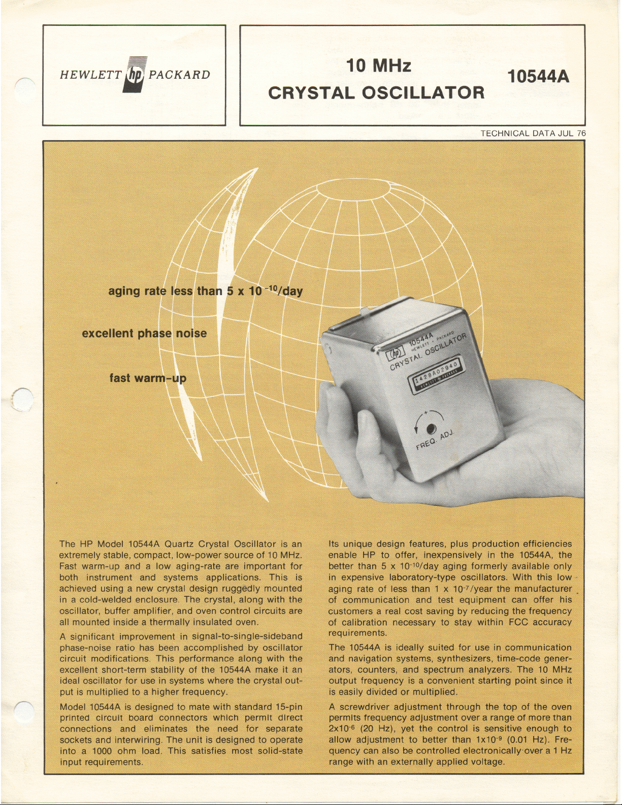
The HP Model 10544A Quartz Crystal Oscillator is an
extremely stable, compact, low power, source of 10
MHz. Fast warm-up and low aging are important for
both instrument and systems applications. This is
achieved using a new crystal design ruggedly mounted
in a cold-welded enclosure. The crystal, along with the
oscillator, buffer amplifier, and oven control circuits
are all mounted inside a thermally insulated oven.
calibration necessary to stay within FCC accuracy
requirements.
The 10544A is ideally suited for use in communication
and navigation systems, synthesizers, time-code gener-
ators, counters, and spectrum analyzers. The 10 MHz
output frequency is a convenient starting point since it
is easily divided or multiplied.
Model 10544A is designed to mate with standard 15-
pin printed circuit board connectors which permit direct
connections and elimrnates the need for separate
sockets and interwiring. The 1000-0hm output imped-
ance satisfies most solid-state input requirements.
Its unique design features, plus production efficiencies
enable HP to offer, inexpensively in the 10544A, the
better than 5 x 10⁻¹°/day aging formerly available only
in expensive laboratory type oscillators. With this low
aging rate of less than 1.5 x 10⁻⁷/year the manufacturer
of communication and test equipment can offer his cus-
tomers a .real cost saving by reducing the frequency of
I
A screwdriver adjustment through the top of the oven
enclosure permits frequency adjustment over a range of
4 x 10⁻⁶ (40 Hz), yet the control is sensitive enough to
allow adjustment to better than 1 x 10⁻⁹ (0.01 Hz).
Frequency can also be controlled electronically over a
1 Hz range with an externally applied voltage.
To permit optimum performance and use of available
voltages, the power inputs for the oscillator/amplifier,
oven controller and oven circuits are available sepa-
rately. However, with a simple external IC regulator a
single voltage regulated to 10 percent may qe used.
Page 10

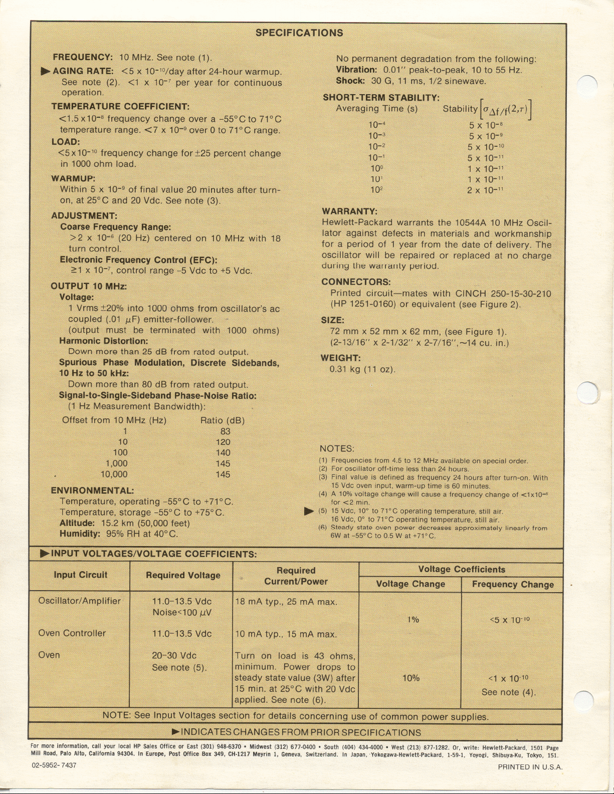
SPECIFICATIONS
FREQUENCY: 10 MHz.(1)
AGING RATE: <5 x 10⁻¹°/day after 24-hour warm-up.(2)
and <1.5 x 10⁻⁷/year.
SHORT TERM STABILITY:
1 x 10-"/1 s Avg. time.
1 x 10-"/10 s Avg. time.
2 x 10⁻¹'/100 s Avg. time.
..INPUT VOl TAGES/VOl TAGE COEFFICIENTS:
Input Circuit
Oscillator/ Amplifier 15 mA
Required Voltage
10.6-11.7 Vdc
Noise <100 ,uV
Oven Controller
Oven
10.6-11.7 Vdc
15-30Vdc
Turn-on load is 50-
Ohms. Power drops to
2'!2W at 25° C after
15 minutes.
NOTE See Input Voltages section for details concerning use of common power supplies
..TEMPERATURE COEFFICIENT: <1 x 10-B frequency
change over a -55° C to 71° C temperature range.
<3 x 10⁻⁹overOto71°C range.
LOAD:<5 x 10⁻¹⁰ frequency change for2500hm load change
WARM UP: Within 5 x 10⁻⁹ of final value 15 minutes after
turn-on, at 25°C(3)
Required
Current/Power
Voltage Change
Voltage Coefficients
1%
5mA
10%
~
Frequency Change
<5 x 10-'0
<1 x 10⁻¹⁰(4)
..ADJUSTMENT:
Coarse Frequency Range: >j:2 x 10⁻⁶ from 10 MHz with
18-turn control.
Electronic Frequency Control (EFC): ~1 x 10⁻⁷. control
range -5 Vdc to +5 Vdc.
CONNECTORS:
Printed circuit -Mates with CINCH 250-15-30-261 (HP
1251-0159) or equivalent.
OUTPUT 10 MHz:
Voltage: 1V rms :!:20% into 1000 Ohms from ac coupled
( .01 I1F) emitter-follower .
Harmonic Distortion: Down more than 25 dB from rated
output.
Nonharmonic Components: Down more than 80 dB from
rated output.
Signal-to-Slngle-Sldeband Phase-Noise Ratio: (1 Hz
Measurement Bandwidth).
Offset from
10 MHz (Hz)
10
100
1,000
10,000
Ratio (dB)
115
120
125
130
..ENVIRONMENT AL:
Temperature, operating -55° C to +71°C.
Temperature, storage -55°C to +75°C.
AltItude: 50,000 feet (15,2 km).
Humidity: 95% AH at 40° C.
Vibration: 0.01 " peak-to-peak, 10 to 55 Hz.
WARRANTY:
Hewlett-Packard warrants the 10544A 10 MHz Oscillator
against defects in materials and workmanship for a period
of 1 year from the date of delivery. The oscillator will be
repaired or replaced at the factory at no charge during the
warranty period.
SIZE:
2-3/4" x 2-1/32" x 2-7/16" (13.6 cu. in.), (6.985 x 5.159 x
6.191 cm) (see Figure 1).
WEIGHT:
11 oz (0.31 kg).
~
~
~ INDt.CAJESOHANGESFR9MPR.I!iii~$peCrFICI\TI0NS
.
~
Page 11

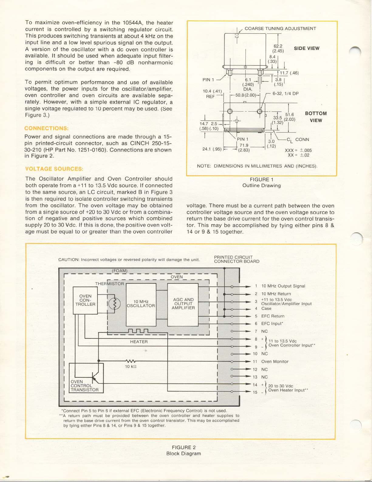
INSTALLATION:
The 10544A 10 MHz Oscillator may be mounted into a
15-pin printed-circuit connector in any convenient
position. The oscillator is secured with 6-32 machine
screws and lock washers using the two threaded mount-
ing studs on its base (see Figure 1 ).
Table A
Pin 1: 10 MHz Output.
Pin 2: Ground
Pin 3: +10.6to11.7Vdc. Oscillator/Amplifier
Input (15 mA nominal).
Pin 4
Oscillator/Amplifier and 10 MHz Signal
Ground.
: EFC Ground (tied internally to pin 4),*
Pin 5:
': EFC Input (Control range -5 to +5 Vdc),*
Pin 6:
'. NC
Pin 7:
I: +10.6 to 11.7 Vdc, Oven Controller Input
Pin 8:
(5 mA nominal).
I: Oven Controller Negative.
Pin 9:
10: NC
Pin 10:
11: Oven Monitor
Pin 11:
2: NC
Pin 12:
3: NC
Pin 13:
4: +15 to 30 Vdc. Oven Power Input, (Turn-
Pin 14:
on load is 50-Ohms. Power drops to 2Y2W
at 25°C after 15 minutes).
15: Oven Power Negative.
Pin 15
"Connect Pin 5 to Pin 6 if external EFC control is not used.
FIGURE 1
Outline Drawing
CONNECTIONS:
~~~~~ '\..~~ ~~~~ ~~~~""' ~~ ~~~ *'-~~'-!:..~~ ~ 1.-.~
pin printed-circuit Connector, such as CINCH 250-15-
.30-261 (HP Part No.1251-0159). Connections are
shown in Figure 2 and listed in Table A.
INPUT VOlTAGES:
The oscillator-amplifier and the oven controller (pins 3
and 8) may be connected to the same 10.6 to 11.7 Vdc
source. However, to isolate controller switching-
transients from the oscillator, the following LC circuit
is recommended:
FIGURE 3
Decoupling Filtel
r-
FIGURE 2
Block Diagra/T
Page 12

OVEN MONITOR:
put voltage or frequency is not within specification,
An output signal is available at pin 11 which indicates
the temperature condition of the oscillator oven. The
signal voltage level depends on the value of oven supply
voltage at pins 14 and 15.
Duty-cycle of the signal at pin 11 depends on the oven
temperature; long duty-cycle at turn-on and short
duty-cycle at operating temperature. The corre-
sponding dc voltage monitored with a high-impedance
voltmeter is; maximum voltage level when the oven is
check the input voltages and determine that the
regulation and noise are within specific-ation. If the
input power or current are substantially different from
those shown in Table A, return the oscillator to HP for
repair. The oven input power should decrease within a
few minutes after turn-on as the oven temperature
stabilizes. Continued full input power indicates a mal-
function of the oven controller and will damage the
oscillator by overheating.
cold (at turn-on) and minimum voltage level when the
oven is at operating temperature.
OPERATION:
Connect the oscillator through a 15-pin printed-circuit
connector. Allow a 24-hour warm-up time for stabili-
zation before adjusting frequency.
SERVICE:
The 10544A is designed for factory repair and field
repair should not be attempted. Repairs are handled
promptly on an exchange basis through the nearest HP
Sales and Service Office.
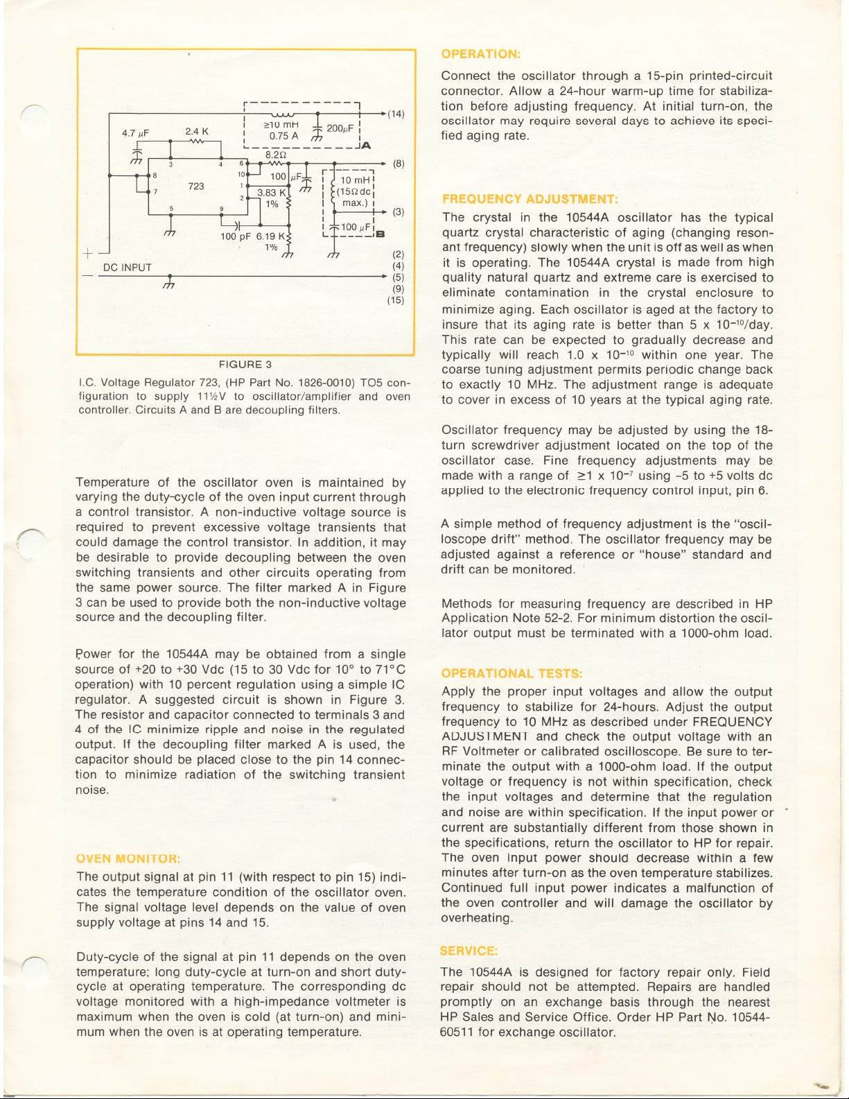
VOl TAGE SOURCES:
FREQUENCY ADJUSTMENT:
Oscillator frequency may be adjusted within a range of
4 x 10⁻⁶ (40 Hz) by using the 18-turn screwdriver ad-
justment located on the top of the oscillator case. Fine
frequency adjustments may be made within a range of
~1 x 10⁻⁷ using -5 to +5 volts dc as a tuning source.
A simple method of frequency adjustment is the "oscil-
"
i
loscope drift" method. The oscillator frequency may
be adjusted against a reference or "house" standard
Since the Oscillator/Amplifier and EFC circuits are not
tied internally to the Oven Controller and Oven circuits,
the voltage to supply the oven may have either a
positive or negative ground or be a combination of
sources to give the required 15 to 30 Vdc. The positive
Oven voltage must be at least two volts above the
positive Oven Controller voltage.
and drift can be monitored.
Methods for measuring frequency are described in
Section III of HP Application Note 52. For minimum
distortion the oscillator output should be terminated
with a 1000-0hm load.
Aging and StabIlIty Measurement:
Refer to HP Application Note 116 and Computing
15 -30 VDC
~ ~ 6(
, 8 1(
jlA723C
7
5 9
T
'-i/--4
lOOpf
8.2 n
~
6.81K ~ 1
, , ..Controller
< 3.83K ( -To
S 1% ~°sc/Amp
1% th
..Oven (14)
To Oven
" (8)
IOmH
10llF (31
Counter Applications Library for information on
methods of making precise aging and short-term
stability measurements of the Model 10544A Oscillator.
Operational Tests
Apply the proper input voltages and allow the output
Voltage Regulator using Fairchild jJ.A723C,
(HP Part No.1820-01961 TO5 Configuration
FIGURE 4
frequency to stabilize for 24-hours. Adjust the output
frequency to 10 MHz as described under FREQUENCY
ADJUSTMENT and check the output voltage with an
RF Voltmeter or calibrated oscilloscope. Be sure to
terminate the output with a 1000-0hm load. If the out-
A source of +15 to +30 Vdc with 10 percent regulation
may be used as a power source if a simple IC regulator
is used. A suggested circuit is shown in Figure 4.
~
For more information, call your local HP Sales Office or East (201) 265.5000 .Midwest (312) 677-0400 .South (404) 436.6181
West (213) 877-1281. Or, write: Hewlett-Packard, 1501 Page Mill Road, Palo Alto, California 94304. In Europe, 1217 Mevrin.Geneva
Printed in USA £# 02-5952-0751
~
Page 13

Page 14

Page 15

Page 16

Page 17

Page 18

Page 19

Page 20

Gerald
Its about 30 years since I had one of these apart for (sucessful) repair
without the aid of any circuit diagram.
At least one can calculate that the nominal crystal current is about 240
uA rms somewhat less than the 1mA in the 10811 with its SC cut crystal.
Bruce
Gerald Molenkamp wrote:
> Hi Bruce,
>
> You are right. I havn't checked my unit against the schematic at all. It is
> well secured calibrated and operating in my HP 5342 operating well within
> the specifications. The scanned schematic came from Leapsecond a few years
> ago, and I have not had to use it as yet. Lets hope it stays that way.
>
> Cheers
>
> Gerald
>
_______________________________________________
time-nuts mailing list
time-nuts@febo.com
https://www.febo.com/cgi-bin/mailman/listinfo/time-nuts
Page 21

Gerald Molenkamp wrote:
> Hi Howard,
>
> Please find attached a schematic of the 10544, hope it helps in anyway.
>
> Regards
>
>
>
> Gerald
>
Gerald
The connection of the 10K oven monitor resistor R12 in the schematic is
incorrect.
In this position only the very small deviations in the oven supply
voltage due to its finite output impedance will be seen as Q4 turns on
and off.
The resistor should surely be connected to the junction of the
darlington (Q4) emitter and the oven heater winding resistor??
The datasheet clearly states that the duty cycle of the oven monitor
varies, as is seen with working 10544As.
Bruce
Page 22

Gerald Molenkamp wrote:
> Hi Bruce,
>
> You are right. I havn't checked my unit against the schematic at all. It is
> well secured calibrated and operating in my HP 5342 operating well within
> the specifications. The scanned schematic came from Leapsecond a few years
> ago, and I have not had to use it as yet. Lets hope it stays that way.
>
> Cheers
>
> Gerald
>
Gerald
On closer inspection it would appear that to be consistent with the
specified output R8 in the AGC cascode amplifier should be 100 ohms as
in the output cascode amplifier that feeds the emitter follower
otherwise the AGC detector will not develop enough output.
Some modifications to the oscillator circuit were made to improve the
phase noise floor by about 15dB between the early and later versions of
the 10544A.
Thus you will need to know if your oscillator is an early or later
production unit.
I suspect the circuit schematic that Tom scanned is for the early
production unit as the ouput cascode amplifier has an RF voltage gain of
about 13.2x (22.4dB) and a corresponding RF input voltage at the base of
the input transistor of about 76mV rms which is quite low.
Bruce
Page 23

CORRECTION
Judging from the oscillator and oven controller voltage ranges Tom's
scanned circuit is actually for the later production models of the
10544A with the improved phase noise specification. The input signal to
the oscillator buffer cascode was probably somewhat smaller than 76mV
rms in the earlier versions.
Bruce
Page 24

Lester Veenstra M0YCM wrote:
> I have a bad 10544 (received from AST) that I am planning to look into.
> No 10 MHz out and very low 12 VDC current.
> Has anyone the translation from HP PN to Commercial equiv for the
> semiconductors ?
> Thanks
> Les
>
> Lester B Veenstra
> M0YCM K1YCM K1YCM/6Y5
>
> Mail Address:
>
> Lester Veenstra
> PSC 45 Box 781
> APO AE 09468
>
> Telephones:
>
> Office 940-6456
> Office +44-(0)1423-846-385
> Home: +44-(0)1943-880-963
> UK Cell +44-(0)7716-298-224
>
>
Lester
A parts conversion list is available at
http://www.hparchive.com/PARTS/300-hpxref.pdf
The part numbers on the circuit schematic are somewhat abbreviated.
54-215 = 1854-0215 = 2N3904.
53-20 = 1853-0020 = 2N3905?? my guess this should work. but stick a
ferrite bead on the base as this device may oscillate with all 3
terminals AC grounded.
26-59 = 1826-0059 = ?? some low bias current opamp with external
frequency compensation LM208??
3-347 = 1853-0347 = MJE700 PNP power Darlington
4-560 = 1854-0560 = MPSA12 NPN small signal darlington
5-10 = 1853-0010 = 2N2646 unijunction transistor
01-535 = 1901-0535 = Silicon RF detector diode probably not Schottky.
02-033 = 1902-0033 = 1N823 6.2V temperature compensated zener reference
diode.
Bruce
Page 25

Lester Veenstra M0YCM wrote:
> I have a bad 10544 (received from AST) that I am planning to look into.
> No 10 MHz out and very low 12 VDC current.
> Has anyone the translation from HP PN to Commercial equiv for the
> semiconductors ?
> Thanks
> Les
>
> Lester B Veenstra
> M0YCM K1YCM K1YCM/6Y5
>
> Mail Address:
>
> Lester Veenstra
> PSC 45 Box 781
> APO AE 09468
>
> Telephones:
>
> Office 940-6456
> Office +44-(0)1423-846-385
> Home: +44-(0)1943-880-963
> UK Cell +44-(0)7716-298-224
>
>
Lester
CORRECTIONS
a 1901-0535 is a schottky RF detector diode - see 10811 parts list.
1826-0059 is not an LM208 which has a part no 1826-0072.
01-40 = 1901-0040 = 1N4148
Bruce
Page 26

Les
Lester Veenstra M0YCM wrote:
> Excellent, Thanks
> Les
>
> Lester B Veenstra
> M0YCM K1YCM K1YCM/6Y5
>
> Mail Address:
>
> Lester Veenstra
> PSC 45 Box 781
> APO AE 09468
>
> Telephones:
>
> Office 940-6456
> Office +44-(0)1423-846-385
> Home: +44-(0)1943-880-963
> UK Cell +44-(0)7716-298-224
>
>
Further correction
1826-0072 is actually a uA208 from Fairchild.
so 1826-0059 could still be an LM208 -different vendor.
Bruce
 Loading...