

Page 1

C 34S G1 UA/HAC 34S G1 UA/HAC 34S G1 UA/HA
C 34S G3 UA /HAC 34S G3 UA /HAC 34S G3 UA /HA
GB
English
Operating Instructions
COOKER AND OVEN
Contents
Operating Instructions,1
Description of the appliance-Overall view,2
Description of the appliance-Control Panel,3
Installation,4
Start-up and use,8
Precautions and tips,11
Care and maintenance,12
Assistance,12
RS
Русский
Руководство по эксплуатации
КУХОННАЯ ПЛИТА С ДУХОВЫМ ШКАФОМ
Содержание
UA
Украінська
Інструкціі з експлуатаціі
КУХНЯ
Зміст
Інструкціі з експлуатаціі,1
Опис установки-Загальнии вигляд,2
Опис установки-Панель управління,3
Встановлення,22
Включення і використання,26
Запобіжні засоби і поради,29
Догляд i технічне обслуговування,30
Допомога,30
RO
Românã
Instrucюiuni de folosire
ARAGAZ ЄI CUPTOR
Sumar
Руководство по эксплуатации,1
Описание изделия-Общий вид,2
Описание изделия-Панель управления,3
Монтаж,13
Включение и эксплуатация,17
Предосторожности и рекомендации,20
Техническое обслуживание и уход,21
Техническое обслуживание,21
Instrucюiuni de folosire,1
Descrierea aparatului- Vedere de ansamblu,2
Descrierea aparatului-Panoul de control,3
Instalare,31
Pornire єi utilizare, 35
Precauюii єi sfaturi,38
Оntreюinere єi curгюire,39
Asistenюг,39
Page 2
14
1
2
3
4
5
6
GB
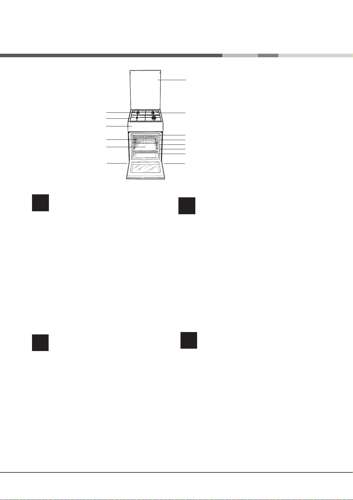
Description of the appliance
Overall view
1 Hob burner
2 Hob Grid
3.Control panel
4.Sliding grill rack
5.DRIPPING pan
6.Adjustable foot
7.Containment surface for spills
8.GUIDE RAILS for the sliding racks
9.position 5
10.position 4
11.position 3
12.position 2
13.position 1
14. Glass Cover *(Available only on certain
models)
7
8
9
10
11
12
13
6
Опис плити
UA
1. Газовий пальник
2. Піддон на випадок переливань
3.Панель управління
4.Полка РЕШІТKИ
5.Полка ДEКО
6.Лапка для налаштування
7.Пoверхня для збирання збiглoї piдини
8.HAПPABЛЯЮЧІ для полиць
9.положення 5
10.положення 4
11.положення 3
12.положення 2
13.положення 1
14.Скляна кришка (Є лише в деяких моделях.)
Загальнии вигляд
Описание изделия
RS
Общий вид
1 Газовые горелки
2 Рабочая поверхность
3 Панель управления
4 Решетка духовки
5 Противень или жарочный лист
6 Регулируемые ножки
7 Электрические конфорки
HAПPAB ЛЯЮЩИE для противеней решеток
8
9 Положение 1
10 Положение 2
11 Положение 3
12 Положение 4
13 Положение 5
Cтеклянная крышка
14
Имеется только в некоторых моделях.)
(
2
RO
Descriere aparatului
Vedere de ansamblu
1.Arzătoare pe gaz
2.Grătare plită
3.Panou frontal de control
4.Grătarul cuptorului
5.Tavă de coacere
6.Picioare reglabile
7.Plită
8.GHIDAJE alunecare rafturi
9.nivelul 5
10. nivelul 5
11.nivelul 5
12.nivelul 5
13.nivelul 5
14.Capacul din sticlă
(prezent doar la anumite modele)
Page 3
1
1
5
3
2
4
2
5
GB
5
5
3
GB
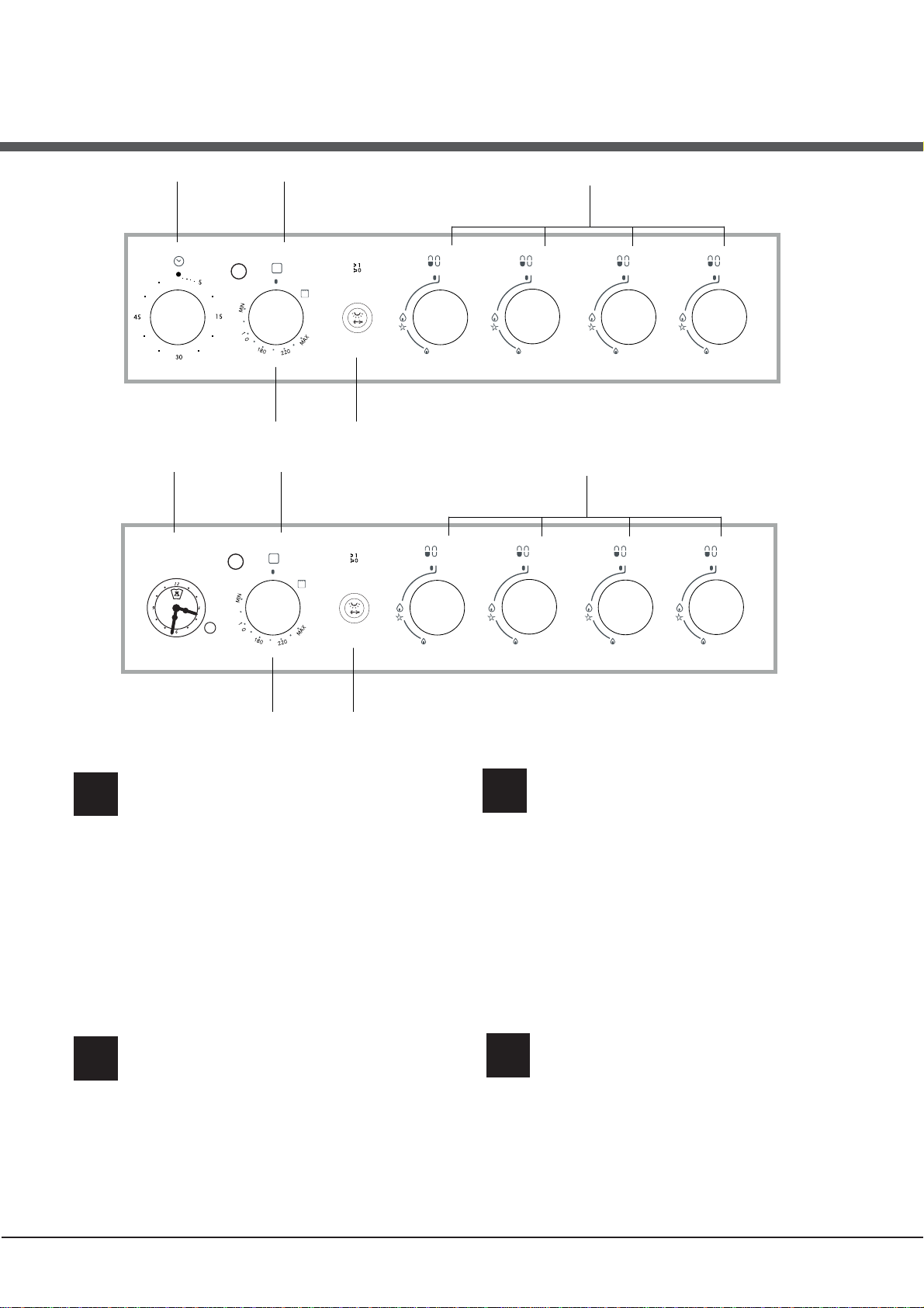
Description of the appliance
Control panel
1.TIMER knob*
2.THERMOSTAT indicator light
3.OVEN AND GRILL CONTROL knob
4.OVEN LIGHT / ROTISSERIE button
5. Hob BURNER control knob
*Available only on certain models
Описание изделия
RS
Панель управления
4
Опис плити
UA
1.Сукоятка ТАЙМЕРА*
2. Індикатор TEPMOCTATУ
3. Ручка ДУХОВКА й гриля
4.КНОПКА РОЖНА та ОСВІТЛЕННЯ ДУХОВКИ
5.Ручки для керування газовими
пальниками на варильній поверхні
*
Є лише в деяких моделях
Панель управління
RO
Descriere aparatului
Panoul de control
1.Таймер*
2.Световой индикатор термостата духового шкафа
3.Рукоятка управления духовкой и грилем
4.Кнопка включения/выключения освещения духовки
5. Рукоятки включения газовых конфорок
варочной панели
*Имеется только в некоторых моделях
1.Buton cronometru*
2.Indicator TERMOSTAT
3.Buton de comandã pentru cuptor i grill
4.Buton pentru activarea luminii din cuptor/ rotisserie
5.Butoane comandi ochiuri aragaz
*prezent doar la anumite modele
3
Page 4
Installation
GB
! Before operating your new appliance please read
this instruction booklet carefully. It contains important
information concerning the safe installation and
operation of the appliance.
! Please keep these operating instructions for future
reference. Make sure that the instructions are kept with
the appliance if it is sold, given away or moved.
! The appliance must be installed by a qualified
professional according to the instructions provided.
! Any necessary adjustment or maintenance must be
performed after the cooker has been disconnected
from the electricity supply.
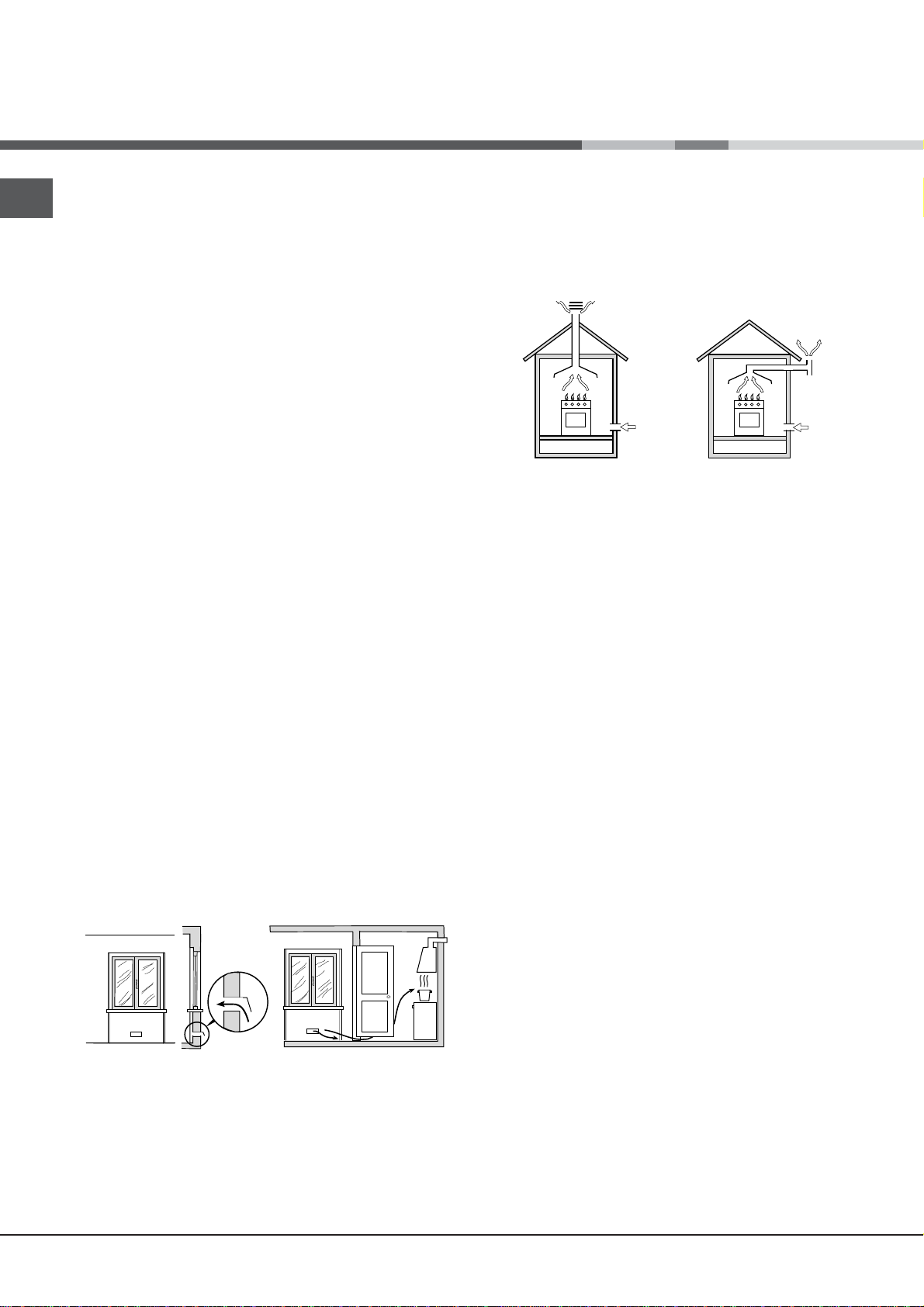
Room ventilation
The appliance may only be installed in permanentlyventilated rooms, according to current national
legislation. The room in which the appliance is installed
must be ventilated adequately so as to provide as
much air as is needed by the normal gas combustion
3
process (the flow of air must not be lower than 2 m
/h
per kW of installed power).
The air inlets, protected by grilles, should have a duct
2
with an inner cross section of at least 100 cm
and
should be positioned so that they are not liable to even
partial obstruction (see gure A).
These inlets should be enlarged by 100% - with a
2
minimum of 200 cm
- whenever the surface of the
hob is not equipped with a flame failure safety device.
When the flow of air is provided in an indirect manner
from adjacent rooms (see gure B), provided that these
are not communal parts of a building, areas with
increased fire hazards or bedrooms, the inlets should
be fitted with a ventilation duct leading outside as
described above.
A B
Adjacent room Room requiring
ventilation
Disposing of combustion fumes
The disposal of combustion fumes should be
guaranteed using a hood connected to a safe and
efficient natural suction chimney, or using an electric
fan that begins to operate automatically every time the
appliance is switched on (see gure).
Fumes channelled
straight outside
Fumes channelled through
a chimney or branched
flue system reserved for
cooking appliances)
! The liquefied petroleum gases are heavier than air
and collect by the floor, therefore all rooms containing
LPG cylinders must have openings leading outside so
that any leaked gas can escape easily.
LPG cylinders, therefore, whether partially or
completely full, must not be installed or stored in rooms
or storage areas that are below ground level (cellars,
etc.). Only the
cylinder being used should be stored in the room; this
should also be kept well away from sources
of heat (ovens, chimneys, stoves) that may cause
the temperature of the cylinder to rise above 50°C.
Positioning and levelling
! It is possible to install the appliance alongside
cupboards whose height does not exceed that of the
hob surface.
! Make sure that the wall in contact with the back of
the appliance is made from a non-flammable, heatresistant material (T 90°C).
A
Ventilation opening for
comburent air
Increase in the gap between
the door and the flooring
! After prolonged use of the appliance, it is advisable to
open a window or increase the speed of any fans used.
4
To install the appliance correctly:
• Place it in the kitchen, dining room or the bed-sit (not
in the bathroom).
• If the top of the hob is higher than the cupboards,
the appliance must be installed at least 200 mm away
from them.
• If the cooker is installed underneath a wall cabinet,
there must be a minimum distance of 420 mm
between this cabinet and the top of the hob.
This distance should be increased to 700 mm if the
wall cabinets are flammable (see gure).
• Do not position blinds behind the cooker or less than
Page 5
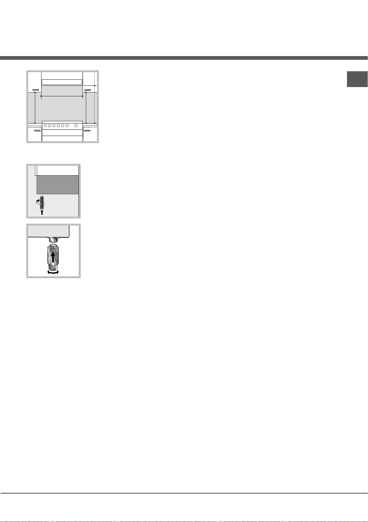
200 mm away from its
HOOD
420
Min.
min.
650
mm. with hood
min.
700
mm. without hood
mm.
600
Min. mm.
420
Min. mm.
sides.
• Any hoods must be
installed according to
the instructions listed in
the relevant operating
manual.
• The socket is compatible with the plug of the
appliance. If the socket is incompatible with the
plug, ask an authorised technician to replace it. Do
not use extension cords or multiple sockets.
! Once the appliance has been installed, the power
supply cable and the electrical socket must be easily
accessible.
! The cable must not be bent or compressed.
GB
Levelling
If it is necessary to level the
appliance, screw the adjustable
feet into the places provided on
each corner of the base of the
cooker (see gure).
The legs* fit into the slots on the
underside of the base of the
cooker.
Electrical connection
Install a standardised plug corresponding to the load
indicated on the appliance data plate (see Technical
data table).
The appliance must be directly connected to the mains
using an omnipolar circuit-breaker with a minimum contact
opening of 3 mm installed between the appliance and the
mains. The circuit-breaker must be suitable for the charge
indicated and must comply with NFC 15-100 regulations
(the earthing wire must not be interrupted by the circuitbreaker). The supply cable must be positioned so that it
does not come into contact with temperatures higher than
50°C at any point.
Before connecting the appliance to the power supply,
make sure that:
• The appliance is earthed and the plug is compliant with
the law.
• The socket can withstand the maximum power of the
appliance, which is indicated by the data plate.
• The voltage is in the range between the values
indicated on the data plate.
* Only available in certain models
! The cable must be checked regularly and replaced
by authorised technicians only.
! The manufacturer declines any liability should
these safety measures not be observed.
Gas connection
Connection to the gas network or to the gas cylinder
may be carried out using a flexible rubber or steel hose,
in accordance with current national legislation and after
making sure that the appliance is suited to the type of gas
with which it will be supplied (see the rating sticker on
the cover: if this is not the case see below). When using
liquid gas from a cylinder, install a pressure regulator
which complies with current national regulations. To
make connection easier, the gas supply may be turned
sideways*: reverse the position of the hose holder with
that of the cap and replace the gasket that is supplied
with the appliance.
! Check that the pressure of the gas supply is
consistent with the values indicated in the Table
of burner and nozzle specifications (see below).
This will ensure the safe operation and durability of
your appliance while maintaining efficient energy
consumption.
Gas connection using a flexible rubber hose
Make sure that the hose complies with current national
legislation. The internal diameter of the hose must
measure: 8 mm for liquid gas supply; 13 mm for
methane gas supply.
Once the connection has been performed, make sure
that the hose:
• Does not come into contact with any parts that reach
temperatures of over 50°C.
• Is not subject to any pulling or twisting forces and
that it is not kinked or bent.
• Does not come into contact with blades, sharp
corners or moving parts and that it is not
compressed.
5
Page 6
GB
A
V
• Is easy to inspect along its whole length so that its
condition may be checked.
• Is shorter than 1500 mm.
• Fits firmly into place at both ends, where it will
be fixed using clamps that comply with current
regulations.
! If one or more of these conditions is not fulfilled
or if the cooker must be installed according to the
conditions listed for class 2 - subclass 1 appliances
(installed between two cupboards), the flexible steel
hose must be used instead (see below).
! If the appliance is connected to a liquid gas supply,
the regulatory screw must be fastened as tightly as
possible.
3. While the burner is alight, quickly change the position of
the knob from minimum to maximum and vice versa several
times, checking that the flame is not extinguished.
! The hob burners do not require primary air
adjustment.
Adapting the oven
Connecting a flexible jointless stainless steel pipe to
a threaded attachment
Make sure that the hose and gaskets comply with
current national legislation.
To begin using the hose, remove the hose holder on the
appliance (the gas supply inlet on the appliance is a
cylindrical threaded 1/2 gas male attachment).
! Perform the connection in such a way that the hose
length does not exceed a maximum of 2 metres,
making sure that the hose is not compressed and does
not come into contact with moving parts.
Checking the connection for leaks
When the installation process is complete, check the
hose fittings for leaks using a soapy solution. Never
use a flame.
Adapting to different types of gas
It is possible to adapt the appliance to a type of gas
other than the default type (this is indicated on the
rating label on the cover).
Adapting the hob
Replacing the nozzles for the
hob burners:
1. Remove the hob grids and
slide the burners off their seats.
2. Unscrew the nozzles using a 7
mm socket spanner (see gure), and replace them with
nozzles suited to the new type of gas(see Burner and
nozzle speci cations table).
3. Replace all the components by following the above
instructions in reverse.
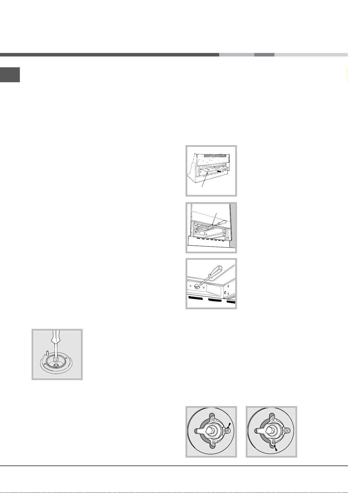
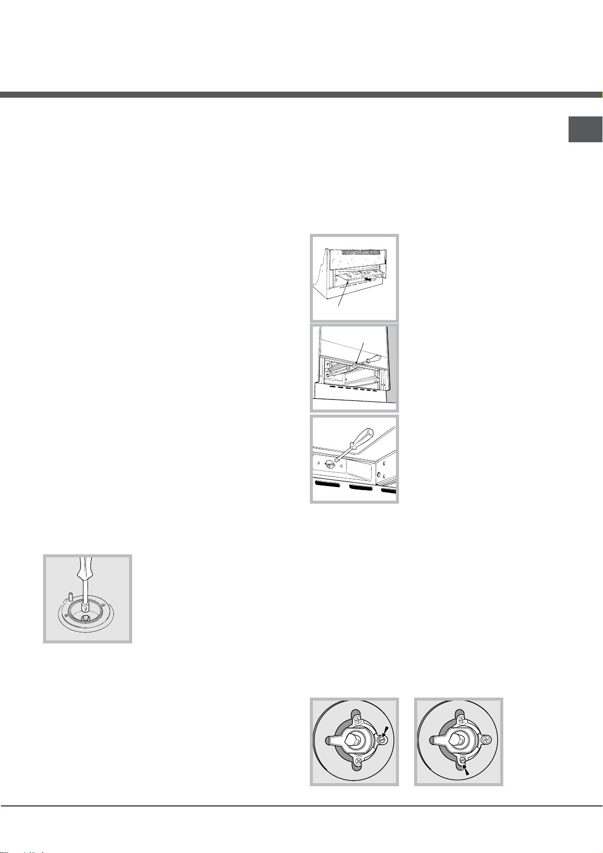
Replacing the oven burner
nozzle:
1. Remove the oven
compartment.
2. Slide out the protection panel
A
(see diagram).
3. Remove the oven burner
after unscrewing the screws V
(see gure).
The whole operation will be
made easier if the oven door is
removed.
4. Unscrew the nozzle using a
special nozzle socket spanner
(see gure) or with a 7 mm
socket spanner, and replace it with a new nozzle that
is suited to the new type of gas (see Burner and nozzle
speci cations table).
Adjusting the gas oven burner’s minimum setting:
1. Light the burner (see Start-up and Use).
2. Turn the knob to the minimum position (MIN)
after it has been in the maximum position (MAX) for
approximately 10 minutes.
3. Remove the knob.
4. Tighten or loosen the adjustment screws on the
outside of the thermostat pin (see gure) until the flame
is small but steady.
Adjusting the hob burners’ minimum setting:
1. Turn the tap to the minimum position.
2. Remove the knob and adjust the regulatory screw,
which is positioned inside or next to the tap pin, until
the flame is small but steady.
6
Page 7
! If the appliance is connected to liquid gas, the
S
S
R
A
adjustment screw must be fastened as tightly as
possible.
5. Turn the knob from the MAX position to the MIN
position quickly or open and shut the oven door,
making sure that the burner is not extinguished.
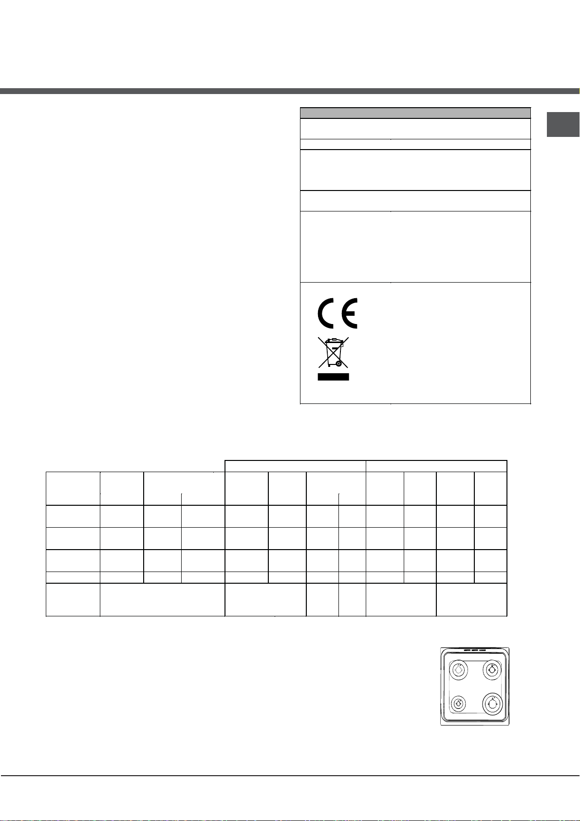
TECHNICAL DATA
Oven dimensions
(HxWxD)
Volume
Useful
measurements
relating to the oven
compartment
Power supply voltage
and frequency
Burners
34x38x44 cm
57 l
width 42 cm
depth 44 cm
height 17 cm
see data plate
may be adapted for use with any
type of gas shown on the data
plate, which is located inside the
flap or, after the oven
compartment has been opened,
on the left-hand wall inside the
oven.
EC Directives: 2006/95/EC dated
12/12/06 (Low Voltage) and
subsequent amendments 2004/108/EC dated 15/12/04
(Electromagnetic Compatibility)
and subsequent amendments 2009/142/EC dated 30/11/09
(Gas) and subsequent
amendments - 93/68/EEC dated
22/07/93 and subsequent
amendments - 2002/96/EC.
1275/2008 (Stand-by/ Off mode)
GB
Table of burner and nozzle specifications
Table 1 Liquid Gas Natural Gas
Burner Diameter
(mm)
Nominal Reduced (mm) (mm) *** ** (mm) (mm)
Fast
(Large)(R)
Semi Fast
(Medium)(S)
Auxiliary
(Small)(A)
Oven - 2.80 1.0 46 80 204 200 119 267 132 257
Supply
Pressures
* At 15°C 1013 mbar-dry gas *** Butane P.C.S. = 49,47 MJ/Kg
** Propane P.C.S. = 50,37 MJ/Kg Natural P.C.S. = 37,78 MJ/m³
100 3.00 0.7 41 87 218 214 128 286 143 286
75 1.90 0.4 30 70 138 136 104 181 118 181
51 1.00 0.4 30 52 73 71 76 95 80 95
Thermal Power
kW (p.c.s.*)
Nominal (mbar)
Minimum (mbar)
Maximum (mbar)
By Pass
1/100
Nozzle
1/100
Flow*
g/h
28-30
20
35
37
25
45
Nozzle
1/100
20
17
25
Flow*
l/h
Nozzle
1/100
Flow*
l/h
13
6,5
18
C 34S G1 UA/HAC 34S G1 UA/HAC 34S G1 UA/HA
C 34S G3 UA /HAC 34S G3 UA /HAC 34S G3 UA /HA
7
Page 8
Start-up and use
F
X
C
GB
Using the hob
Lighting the burners
For each BURNER knob there is a complete ring showing
the strength of the flame for the relevant burner.
To light one of the burners on the hob:
1. Bring a flame or gas lighter close to the burner.
2. Press the BURNER knob and turn it in an
anticlockwise direction so that it is pointing to the
maximum flame setting .
3. Adjust the intensity of the flame to the desired level
by turning the BURNER knob in an anticlockwise
direction. This may be the minimum setting , the
maximum setting or any position in between the two.
If the appliance is fitted with an electronic lighting
device* (see gure), press the ignition button, marked
with the symbol
hold the BURNER knob down
and turn it in an anticlockwise
direction, towards the
maximum flame setting, until
the burner is lit.
Several models are equipped
with an ignition device
which is built into the knob; in this case the electronic
ignition device* is present (C) but the ignition button
is not. Simply press the BURNER knob and turn it
in an anticlockwise direction so that it is pointing
to the maximum flame setting, until the burner is lit.
The burner may be extinguished when the knob is
released. If this occurs, repeat the operation, holding
the knob down for a longer period of time.
! If the flame is accidentally extinguished, switch off the
burner and wait for at least 1 minute before attempting
to relight it.
If the appliance is equipped with a flame failure safety
device*(X), press and hold the BURNER knob for
approximately 2-3 seconds to keep the flame alight
and to activate the device.
To switch the burner off, turn the knob until it reaches
the stop position •.
, then
on the amount of gas consumed, it is recommended
that only pans that have a lid and a flat base are used.
They should also be suited to the size of the burner.
Burner ř Cookware diameter (cm)
Fast (R) 24 - 26
Semi Fast (S) 16 - 20
Auxiliary (A) 10 - 14
To identify the type of burner, please refer to the
diagrams contained in the “Burner and nozzle
specifications”.
Using the oven
! The first time you use your appliance, heat the empty
oven with its door closed at its maximum temperature
for at least half an hour. Ensure that the room is well
ventilated before switching the oven off and opening
the oven door. The appliance may emit a slightly
unpleasant odour caused by protective substances
used during the manufacturing process burning away.
! Before operating the product, remove all plastic film
from the sides of the appliance.
! Never put objects directly on the bottom of the oven;
this will avoid the enamel coating being damaged.
Only use position 1 in the oven when cooking with the
rotisserie spit.
Lighting the oven
To light the oven burner, bring a flame or gas lighter
close to opening F (see gure) and press the OVEN
control knob while turning it in an anticlockwise
direction until it reaches the MAX position.
If, after 15 seconds, the burner
is still not alight, release the
knob, open the oven door and
wait for at least 1 minute before
trying to light it again.
! The oven is fitted with a
safety device and it is therefore
Practical advice on using the burners
WARNING! The glass lid can break
For the burners to work in the most
in if it is heated up. Turn off all the
efficient way possible and to save
burners and the electric plates before
closing the lid. *Applies to the models
with glass cover only.
8
control knob down for approximately 6 seconds.
! If the flame is accidentally extinguished, switch off the
burner and wait for at least 1 minute before attempting
to relight the oven.
* Only available in certain models.
necessary to hold the OVEN
Page 9
Adjusting the temperature
To set the desired cooking temperature, turn the
OVEN control knob in an anticlockwise direction.
Temperatures are displayed on the control panel and
may vary between MIN (140°C) and MAX (250°C).
Once the set temperature has been reached, the oven
will keep it constant by using its thermostat.
Grill
By turning the OVEN control knob in an anticlockwise
direction until it reaches the
ray grill is activated. The grill enables the surface of
food to be browned evenly and is particularly suitable
for roast dishes, schnitzel and sausages. Place the
rack in position 4 or 5 and the dripping pan in position
1 to collect fat and prevent the formation of smoke.
! The GRILL indicator light shows when the grill is
operating.
position, the infrared
Timer*
To activate the Timer proceed as follows:
1. Turn the TIMER knob in a clockwise direction for
almost one complete revolution to set the buzzer.
2. Turn the TIMER knob in an anticlockwise direction
to set the desired length of time.
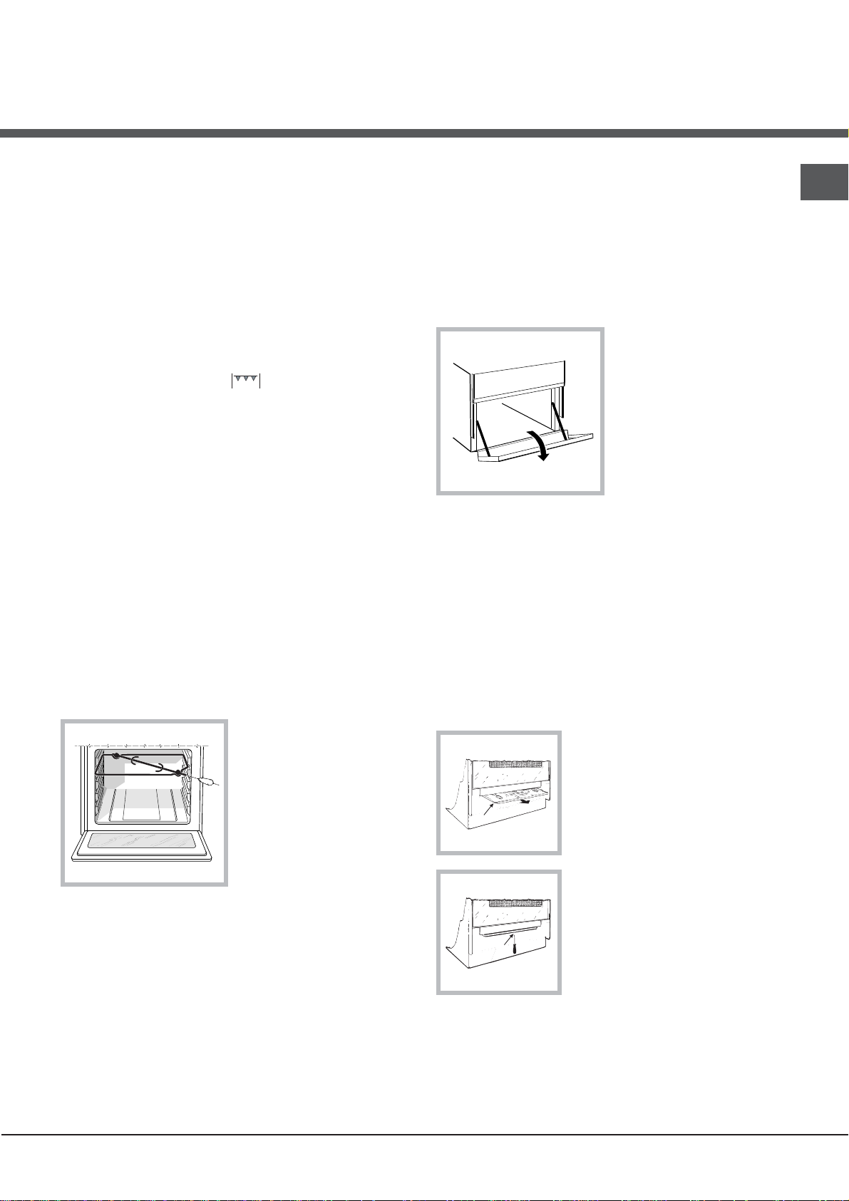
Lower compartment*
There is a compartment underneath the oven that may
be used to store oven
accessories or deep
dishes. To open the door
pull it downwards (see
gure).
! The internal surfaces of
the compartment (where
present) may become hot.
GB
! Always use the grill with the oven door shut; this
achieves better cooking results and saves energy
(approximately 10%).
Turnspit
To operate the rotisserie (see diagram) proceed as
follows:
1. Place the dripping
pan in position 1.
2. Place the rotisserie
support in position 4 and
insert the spit in the hole
provided on the back
panel of the oven.
3. Acitvate the function
by pressing the
TURNSPIT button.
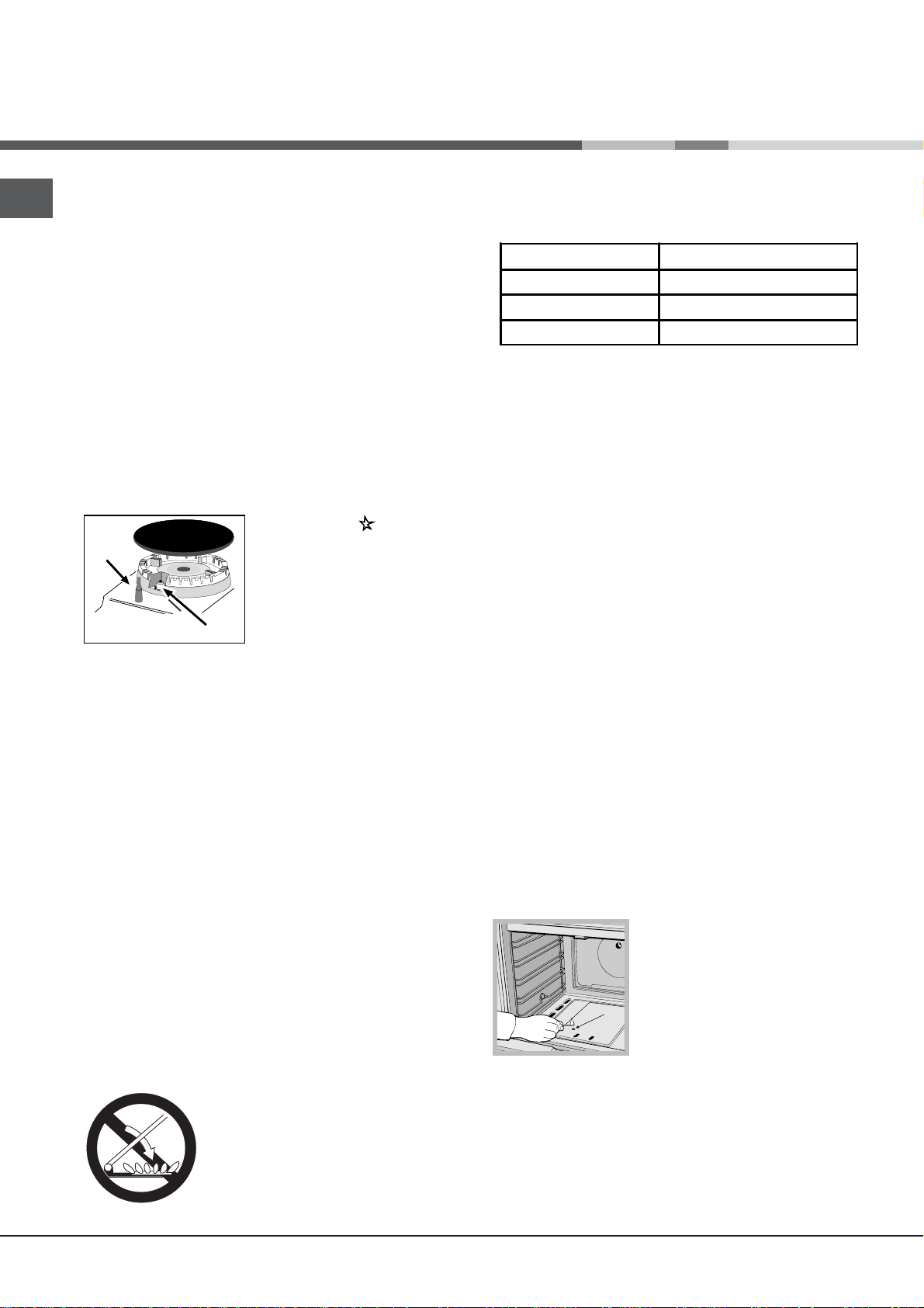
! Do not place flammable materials in the lower oven
compartment.
In gas cooker models, there is a sliding protection layer
A that shields the lower compartment from the heat
generated by the burner (see gure).
To remove the sliding protection remove the screw S
(see gure). To replace it, lock it
in place with the screw S.
A
! Before using the oven make
sure that the sliding protection
is fixed correctly.
S
Oven light
The light may be switched on at any moment by
pressing the OVEN LIGHT button.
* Only available in certain models.
9
Page 10
GB
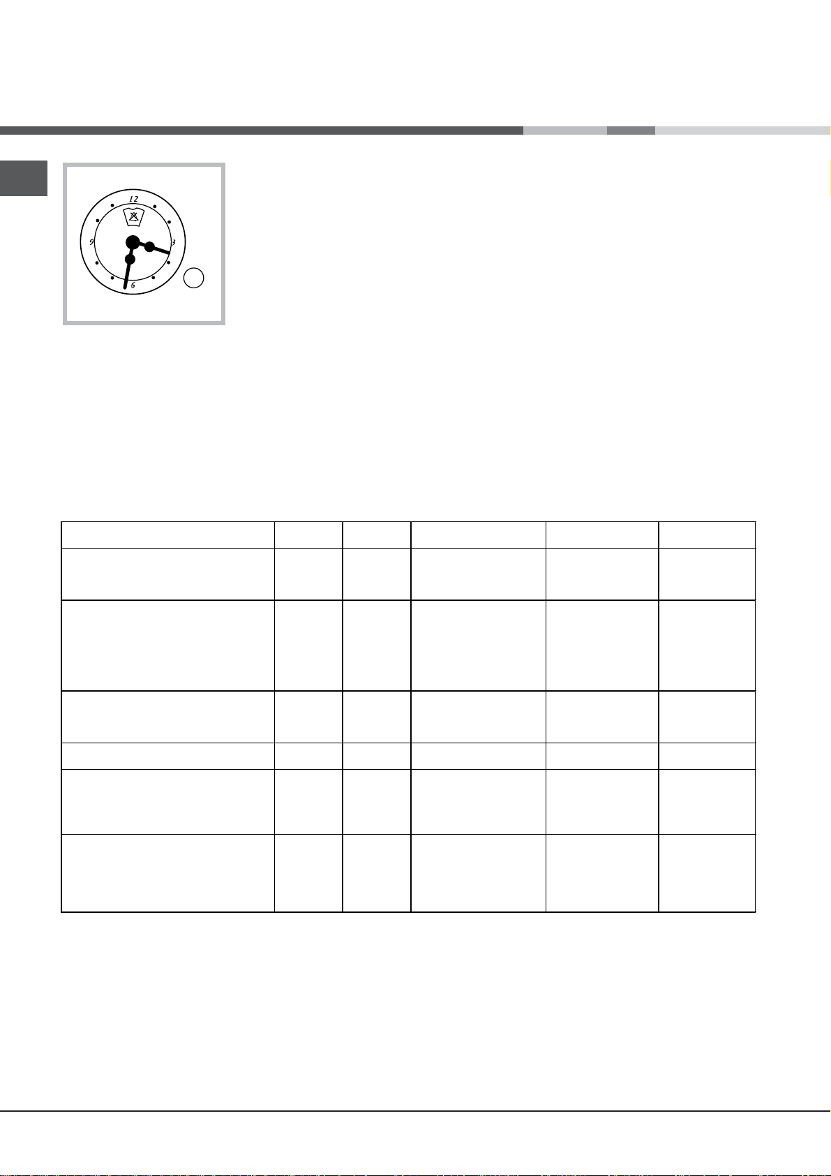
Clock with Country Style timer *
How to reset the correct time
The oven must be plugged in.
Pull the knob and turn it clockwise until you set the
correct time.
Oven cooking advice table
! !
! The programmer is electrically powered, therefore
! !
in the event of a power shortage, it will stop working
for the entire duration of the same. Following this
power failure, the correct time will have to be reset.
Timer Feature
The timer feature allows you to enter a given amount
of time from which the timer begins to count down.
This feature does not turn the oven on or off; it
merely sounds when the time has elapsed.
How to set the timer
Turn the knob clockwise until the marker lines up
with the desired time (internal scale), which can be
seen in the “window”.
The time countdown will begin immediately.
To interrupt the timer buzzer, or to use only the clock
feature, set the marker to the ! symbol.
Foods
Pasta
Lasagne
Cannelloni
Gratin dishes
Meat
Veal
Chicken
Duck
Rabbit
Pork
Lamb
Fish
Mackerel
Dentex
Trout baked in foil
Pizza
Neapolitan-style
Pies
Biscuits
Tart
Savoury pies
Leavened cakes
Grilled foods
Veal steak
Cutlets
Hamburgers
Mackerel
Toast
Weight (in
kg)
2.5
2.5
2.5
1.5
1.5
1.8
2.0
2.1
1.8
1.1
1.5
1.0
1.0
0.5
1.1
1.0
1.0
1
1.5
1
1
4 шт.
Rack
position
2
2
2
3
3
3
3
3
3
3
3
3
4
4
4
4
4
4
4
3
4
4
Preheating time (min)
200-210
200-210
210-220
180-200
180-200
180-200
210-220
200
200
200
200
200
200
180
180
180
170
5
5
5
5
5
Recommended
Temperature (°C)
10
10
10
10
10
10
10
10
10
10
10
10
15
15
15
15
15
Cooking time
(minutes)
100-110
100-105
-
-
-
-
-
75-85
50-60
50-60
95-100
90-100
70-80
70-80
45-50
45-55
45-50
20-25
25-35
40-45
50-55
40-45
15-20
20
20-30
15-20
4-5
NB: cooking times are approximate and may vary according to personal taste. When cooking using the grill, the
dripping pan must always be placed on the 1st oven rack from the bottom.
* Only available in certain models.
10
Page 11
Precautions and tips
! This appliance has been designed and manufactured in
compliance with international safety standards.
The following warnings are provided for safety reasons and
must be read carefully.
General safety
• These instructions are only valid for the countries
whose symbols appear in the manual and on the serial
number plate.• The appliance was designed for domestic
use inside the home and is not intended for commercial or
industrial use.
• The appliance must not be installed outdoors, even in
covered areas. It is extremely dangerous to leave the
appliance exposed to rain and storms.
• Do not touch the appliance with bare feet or with wet or
damp hands and feet.
• The appliance must be used by adults only for
the preparation of food, in accordance with the
instructions outlined in this booklet. Any other
use of the appliance (e.g. for heating the room)
constitutes improper use and is dangerous.
The manufacturer may not be held liable for any
damage resulting from improper, incorrect and
unreasonable use of the appliance.
• The instruction booklet accompanies a class 1 (insulated)
or class 2 - subclass 1 (recessed between 2 cupboards)
appliance.
• Keep children away from the oven.
• Make sure that the power supply cables of other electrical
appliances do not come into contact with the hot parts of
the oven.
• The openings used for the ventilation and dispersion of
heat must never be covered.
• Do not close the glass hob cover (selected models only)
when the burners are alight or when they are still hot.
• If the appliance breaks down, under no circumstances
should you attempt to repair the appliance yourself.
Repairs carried out by inexperienced persons may cause
injury or further malfunctioning of the appliance. Contact
Assistance.
• Do not rest heavy objects on the open oven door.
• The appliance should not be operated by people
(including children) with reduced physical, sensory
or mental capacities, by inexperienced individuals
or by anyone who is not familiar with the product.
These individuals should, at the very least, be
supervised by someone who assumes responsibility
for their safety or receive preliminary instructions
relating to the operation of the appliance.
• Do not let children play with the appliance.
Disposal
• When disposing of packaging material: observe local
legislation so that the packaging may be reused.
• The European Directive 2002/96/EC relating to Waste
Electrical and Electronic Equipment (WEEE) states that
household appliances should not be disposed of using
the normal solid urban waste cycle. Exhausted appliances
should be collected separately in order to optimise
the cost of re-using and recycling the materials inside
the machine, while preventing potential damage to the
atmosphere and to public health. The crossed-out dustbin
is marked on all products to remind the owner of their
obligations regarding separated waste collection.
Exhausted appliances may be collected by the public
waste collection service, taken to suitable collection areas
in the area or, if permitted by current national legislation,
they may be returned to the dealers as part of an
exchange deal for a new equivalent product.
All major manufacturers of household appliances
participate in the creation and organisation of systems for
the collection and disposal of old and disused appliances.
GB
• Always use oven gloves when placing cookware in the
oven or when removing it.
• Do not use flammable liquids (alcohol, petrol, etc...) near
the appliance while it is in use.
• Do not place flammable material in the lower storage
compartment or in the oven itself. If the appliance is
switched on accidentally, it could catch fire.
• Always make sure the knobs are in the • position and that
the gas tap is closed when the appliance is not in use.
• When unplugging the appliance, always pull the plug from
the mains socket; do not pull on the cable.
• Never perform any cleaning or maintenance work without
having disconnected the appliance from the electricity
mains.
Respecting and conserving the environment
• You can help to reduce the peak load of the electricity
supply network companies by using the oven in the hours
between late afternoon and the early hours of the morning.
• Check the door seals regularly and wipe them clean to
ensure they are free of debris so that they adhere properly
to the door, thus avoiding
heat dispersion.
11
Page 12
Care and maintenance
GB
Switching the appliance off
Disconnect your appliance from the electricity supply
before carrying out any work on it.
Cleaning the appliance
! Do not use abrasive or corrosive detergents such as
stain removers, anti-rust products, powder detergents
or sponges with abrasive surfaces: these may scratch
the surface beyond repair.
! Never use steam cleaners or pressure cleaners on
the appliance.
• It is usually sufficient simply to wash the hob using a
damp sponge and dry it with absorbent kitchen roll.
• The stainless steel or enamel-coated external parts
and the rubber seals may be cleaned using a
sponge that has been soaked in lukewarm water
and neutral soap. Use specialised products for the
removal of stubborn stains. After cleaning, rinse well
and dry thoroughly. Do not use abrasive powders or
corrosive substances.
remaining drops of water should also be dried.
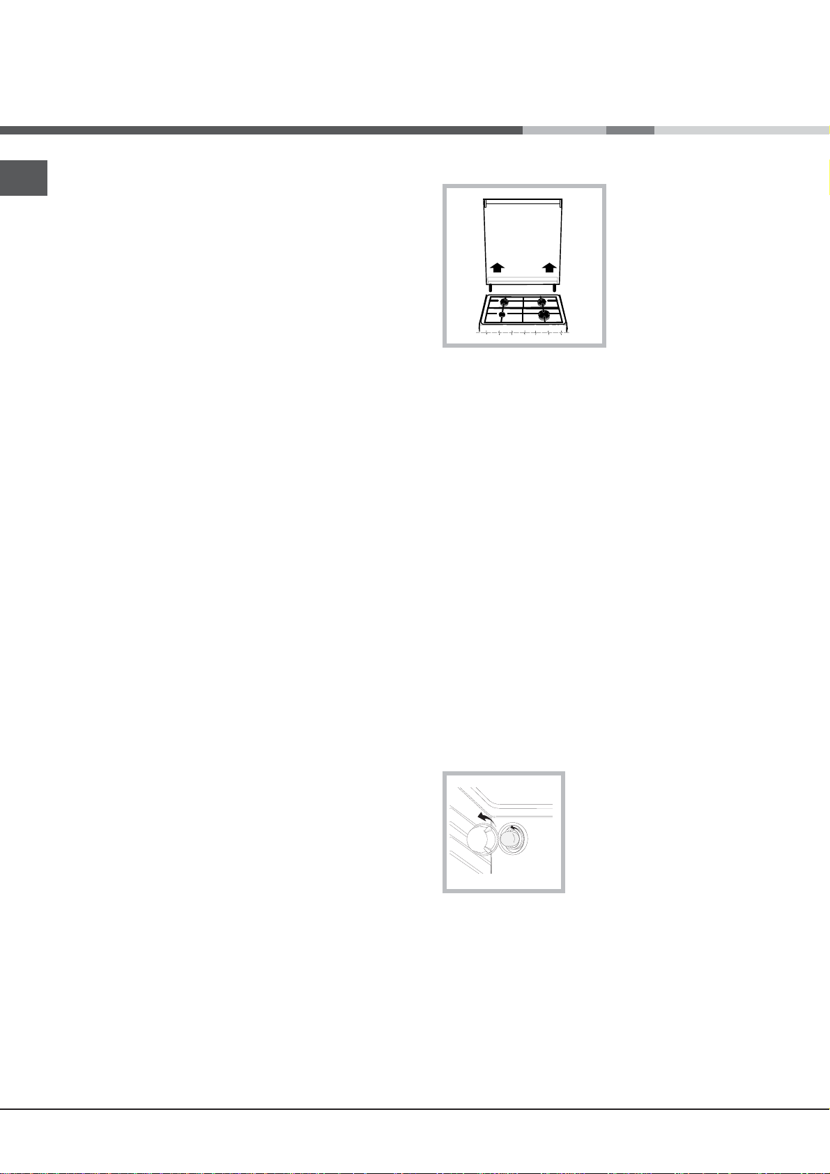
The cover
If the cooker is fitted with
a glass cover, this cover
should be cleaned using
lukewarm water. Do not
use abrasive products.
It is possible to remove
the cover in order to make
cleaning the area behind
the hob easier. Open
the cover fully and pull it
upwards (see gure).
! Do not close the cover when the burners are alight or
when they are still hot.
Inspecting the oven seals
Check the door seals around the oven periodically. If
the seals are damaged, please contact your nearest
Authorised After-sales Service Centre. We recommend
that the oven is not used until the seals have been
replaced.
• The hob grids, burner caps, flame spreader rings
and the hob burners can be removed
to make cleaning easier; wash them in hot water and
non-abrasive detergent, making sure all burnt-on
residue is removed before drying them thoroughly.
• For hobs with electronic ignition, the terminal part of
the electronic lighting devices should be cleaned
frequently and the gas outlet holes should be
checked for blockages.
• The inside of the oven should ideally be cleaned
after each use, while it is still lukewarm. Use hot
water and detergent, then rinse well and dry with a
soft cloth. Do not use abrasive products.
Clean the glass part of the oven door using a
•
sponge and a non-abrasive cleaning product, then
dry thoroughly with a soft cloth. Do not use rough
abrasive material or sharp metal scrapers as these
could scratch the surface and cause the glass to
crack.
• The accessories can be washed like everyday
crockery, and are even dishwasher safe.
• Stainless steel can be marked by hard water that
has been left on the surface for a long time, or by
aggressive detergents containing phosphorus.
After cleaning, rinse well and dry thoroughly. Any
Gas tap maintenance
Over time, the taps may become jammed or difficult to
turn. If this occurs, the tap must be replaced.
! This procedure must be performed by a qualified
technician who has been authorised by the
manufacturer.
Replacing the oven
light bulb
1. After disconnecting the
oven from the electricity mains,
remove the glass lid covering
the lamp socket (see gure).
2. Remove the light bulb and
replace it with a similar one: voltage 230 V, wattage 25
W, cap E 14.
3. Replace the lid and reconnect the oven to the
electricity supply.
Assistance
Please have the following information handy:
• The appliance model (Mod.).
• The serial number (S/N).
This information can be found on the data plate located
on the appliance and/or on the packaging.
12
Page 13

Установка
! Важно сохранить данное руководство для его
последующих консультации. В случае продажи,
передачи или переезда проверьте, чтобы данное
руководство сопровождало изделие.
! Внимательно прочитаите инструкции: в них
содержатся важные сведения об установке,
эксплуатации и безопасности изделия.
! Установка изделия производится в соответствии
с данными инструкциями квалифицированными
специалистами.
! Любая операция по
регуляции или техническому
обслуживанию должна производиться только
после отсоединения кухоннои плиты от сети
электропитания.
Вентиляция помещении
Изделие может быть установлено в помещениях
с постояннои вентиляциеи в соответствии с
деиствующими национальными нормативами. В
помещении, в котором устанавливается изделие,
должен быть обеспечен приток воздуха в объеме,
необходимом для оптимального горения газа (расход
воздуха
не должен быть меньше 2 м3/час на 1 кВт
установленнои мощности).
Вентиляционные отверстия, защищенные
решетками, должны иметь воздуховод площадью не
2
менее 100 мм
полезного сечения и распологаться
таким образом, чтобы их нельзя было закрыть, даже
частично (см. рисунок А).
Эти отверстия должны быть увеличины на 100% - то
2
есть иметь минимальную площадь 200 см
- если
варочная панель не оснащена предохранительным
устроиством отсутствия пламени и если воздух
в помещение поступает из смежных помещении
(см. рисунок В) – при условии, что это не общая
площадь здания, не пожароопасное помещение или
спальня - оснащенных воздуховодом, выходящим на
улицу, как описано выше.
A
A
Вентиляционные
отверстия для притока
Смежное
помещение
B
Увеличение зазора между
дверью и полом
Вентилируемое
помещение
воздуха
! После продолжительного использования изделия
рекомендуется открыть
окно или включить более
интенсивныи режим вентиляторов.
Дымоудаление
Дымоудаление должно осуществляться через вытяжнои
зонт, соединенныи с эффективным дымоходом с
натуральнои тягои, или посредством электровентилятора,
которыи автоматически включается каждыи раз при
включении изделия (см. рисунок).
Прямое
дымоудаление в
атмосферу
Дымоудаление через камин или
дымоход с медным покрытием
(для кухонных устроиств для
приготовления пищи)
! Сжиженные натуральные газы тяжелее воздуха,
застиваются внизу, по этои причине помещения
для хранения баллонов с СНГ
должны иметь
внетиляционные отверстия у пола для вентиляции
возможных утечек газа.
Баллоны с СНГ, полные или частично
израсходованные, не дожны размещаться или
храниться в помещениях или хранилищах,
расположенных в подземных помещениях (подвалы,
и т.д.). Храните в помещении только рабочии баллон,
установив его вдали от источников тепла (духовок,
каминов, печеи), которые
могут нагреть его до
температуры выше 50°C.
Расположение и нивелировка
! Изделие может быть установлено рядом с
кухонными элементами, высота которых не
превышает поверхность варочнои панели.
! Проверьте, чтобы стена, к которои прилегает
задняя часть изделия, была из невозгораемого
материала и устоичивои к теплу (Т 90°C).
Порядок монтажа:
• изделие может быть установлено на кухне, в
столовои или в однокомнатнои квартире (не
ваннои комнате);
• если варочная панель кухоннои плиты выше
мебельных элементов, необходимо отодвинуть их
от плиты на расстояние не менее 200 мм.
• если кухонная плита устанавливается под
навесным шкафом, он должен располагаться на
высоте не менее 420 мм от поверхности варочнои
панели.
Это расстояние должно быть 700 мм, если
навесные шкафы выполнены
из возгораемого
материала (см. рисунок);
• не заправляите занавески за кухонную плиту и не
приближаите их на расстояние меньше 200 мм.
в
RS
13
Page 14

RS
HOOD
420
Min.
min.
650
mm. with hood
min.
700
mm. without hood
mm.
600
Min. mm.
420
Min. mm.
• возможная кухонная
вытяжка должна
быть установлена
в соответствии
с инструкциями,
приведенными
в техническом
руководстве к вытяжке.
! Изделие должно быть установлено таким образом,
чтобы электрическии кабель и электророзетка были
легко доступны.
! Электрическии кабель изделия не должен быть
согнут или сжат.
! Регулярно проверяите состояние кабеля
электропитания и при необходимости поручаите его
замену только уполномоченным техникам.
Выравнивание
При необходимости
выровнять изделие вкрутите
в специальные отверстия по
углам в основании кухоннои
плиты прилагающиеся
регуляционные ножки (см.
рисунок).
Прилагающиеся ножки*
вставляются под основание
кухоннои плиты.
Электрическое подключение
Установите на кабель электропитания
нормализованную штепсельную вилку, расчитанную
на нагрузку, указанную на заводскои табличке
изделия (см. табличку с техническими данными).
В случае прямого подключения к сети электропитания
между кухоннои плитои и сетью необходимо установить
мультиполярныи выключатель с минимальным
расстоянием между контактами 3 мм, расчитанныи на
данную нагрузку и соответствующии нормативу NFC
15-100 (выключатель
заземления). Кабель электропитания должен быть
расположен таким образом, чтобы ни в однои точке его
температура не превышала температуру помещения
более чем на 50°C.
Перед подсоединением кабеля проверьте
следующее:
• электрическая розетка должна быть соединена с
заземлением и соответствовать нормативам;
• электрическая розетка должна быть рассчитана
на максимальную потребляемую мощность
изделия, указанную на заводскои таблике;
• напряжение и частота тока сети должны
соответствовать электрическим данным изделия;
• электрическая розетка должна быть совместима
со штепсельнои вилкои изделия. В противном
случае замените розетку или вилку; не
используите удлинители или троиники.
*Имеется только в некоторых моделях
14
не должен размыкать провод
! Фирма снимает с себя всякую
ответственность
в случае несоблюдения вышеописанных
правил.
Подсоединение к газопроводу
Подсоединение к газопроводу или к газовому
баллону выполняется посредством гибкого
резинового или стального шланга в соответствии с
деиствующими национальными нормативами, после
проверки настроики изделия на тип используемого
газа (см. этикетку настроики на крышке: в противном
случае см. ниже). В случае использования
сжиженного газа из баллона необходимо
установить регуляторы давления, соответствующие
деиствующему
облегчения подсоединения газовыи патрубок
является ориентируемым*: поменяите местами
крепежную блокировочную гаику на заглушку и
замените прилагающееся уплотнение.
! Для надежного функционирования, рационального
использования энергии и более длительного срока
службы изделия проверьте, чтобы давление подачи
газа соответствовало значениям, указанным в
таблице «Характеристики газовых конфорок и
форсунок» (см. ниже).
Газовое подсоединение посредством резинового
шланга
Проверьте, чтобы шланг соответствовал
деиствующим национальным нормативам.
Внутреннии диаметр шланга должен быть: 8 мм для
сжижженного газа; 13 см для газа метана.
После подсоединения проверьте, чтобы шланг:
• не касался частеи, температура которых может
превысить 50°C;
• не был растянут, перекручен, сжат или заломлен;
• не касался режущих предметов, острых углов
подвижных предметов и не был сжат;
• был легко доступен для проверки по всеи длине;
• не был длиннее 1500 мм;
• был прочно закреплен с обоих концов при
помощи хомутов, соответствующих деиствующим
национальным нормативам.
! Если одно или несколько из вышеописанных
условии не будет соблюдено, и если кухонная плита
национальному нормативу. Для
,
Page 15
A
V
устанавливается в условиях класса 2, подгруппа
1 (изделие, встроенное между двух мебельных
элементов), необходимо использовать гибкии
стальнои шланг (см. ниже).
Газовое подсоединение посредством шланга
из нержавеющеи стали со сплошнои оплеткои с
резьбовыми соединениями.
Проверьте, чтобы шланг и уплотнения
соответствовали деиствующим национальным
нормативам.
Для подсоединения шланга снимите блокировочную
гаику с изделия (патрубок подачи
газа в изделие имеет
цилиндрическу резьбу Ѕ газ «папа»).
! Длина подсоединяемого шланга не должна
превышать 2 метра при максимальном растяжении.
Проверьте, чтобы шланг не касался подвижных
деталеи, которые могут его сжать.
Проверка уплотнения
! Конфорки варочнои панели не нуждаются в
какои-
либо регуляции первичного воздуха.
Настроика духового шкафа
Замените форсунку газовои горелки духового шкафа:
1. выньте ящик для подогрева продуктов;
2. снимите выдвижную панель А (см. рисунок);
3. выньте горелку из духового
шкафа, сняв V-бразныи винт
(см. рисунок);
выполнение этои операции
можно облегчить, сняв дверцу
духового шкафа.
RS
По завершении подсоединения проверьте прочность
уплотнения всех патрубков при помощи мыльного
раствора, но никогда не пламенем.
Настроика на различные типы газа
Изделие может быть настроено на тип газа,
отличающиися от оригинального (указан на этикетке
настроики на крышке).
Настроика варочнои панели
Порядок замены форсунок конфорок на варочнои
панели:
1. снимите решетки с варочнои панели и выньте
горелки из своих гнезд;
2. отвинтите форсунки при помощи полого гаечного
ключа 7 мм (см. рисунок) и замените их
расчитанные на новыи тип газа
(см. таблицу Характеристики
горелок и форсунок);
3. восстановите на место все
комплектующие, выполняя
операции в обратном порядке по
отношению к описанным выше.
Порядок регуляции
минимального пламени конфорок на варочнои
панели:
1. поверните рукоятку в положение минимального
пламени;
2. снимите рукоятку и поверните регуляционныи винт,
расположенныи внутри или рядом со стержнем крана,
вплоть до получения стабильного малого пламени.
! В случае использования сжиженного газа винт
регуляции должен быть завинчен до упора.
3. проверьте, чтобы конфорка не гасла при резком
повороте крана из положения максимального
пламени в положение минимального пламени.
на форсунки,
4. отвинтите форсунку горелки
при помощи
специального
полого ключа для форсунок (см.
рисунок) или полого ключа
7 мм и замените форсунку
на новую, расчитанную на
новыи тип газа (см. таблицу
Характеристики горелок и
форсунок).
Регуляция минимального
пламени горелки духового
шкафа:
1. включите горелку (см. Пуск и Эксплуатация);
2. оставьте рукоятку примерно в течение 10 минут в
положении максимального
пламени (МАКС), затем
поверните ее в положение минимального пламени
(МИН);
3. снимите рукоятку;
4. поверните регулировочныи винт, расположенныи
внутри стержня термостата (см. рисунок), вплоть до
получения малого стабильного пламени.
! В случае использования сжиженного газа винт
регуляции должен быть завинчен до упора;
5. проверьте, чтобы горелка не гасла при резком
вращении
рукоятки-регулятора из положения МАКС
в положение МИН или при резком открывании или
закрывании дверцы духовки.
15
Page 16

RS
S
S
R
A
S
A
Отвинтите винт S и снимите выдвижную панель (см.
рисунок). Для
ее обратнои установки завинтите винт
S.
! Перед использованием
духового шкафа проверьте,
чтобы выдвижная панель
была прочно зафиксирована.
ВНИМАНИЕ! При нагреве
стеклянная крышка может
лопнуть. Прежде чем закрыть ее,
выключить все конфорки или
электрические горелки.*Только
для моделей со стеклянной
крышкой
ТЕХНИЧЕСКИЕ ДАННЫЕ
Габаритные
размеры духового
34x38x44 см
шкафа ВхШхГ
Объем
Рабочие размеры
ящика для
разогревания
пищи
Напряжение и
частота
электропитания
л 57
ширина 42 см.
глубина 44 см.
высота 17 см.
см. табличку с техническими
характеристиками
настраиваются на любой тип
газа, указанный на заводской
Горелки
табличке с внутренней стороны
откидной крышки или на левой
внутренней стенке ящика для
разогревания пищи.
Директива ЕС: 2006/95/EC от
12/12/06 (Низкое напряжение) с
последующими изменениями –
2004/108/ЕC от 15/12/04
(Электромагнитная
совместимость) с
последующими изменениями –
2009/142/ЕC от 30/11/09 (Газ) -
90/68/ЕЕC от 22/07/93 с
последующими изменениями –
2002/96/ЕС.
1275/2008 (Stand-by/ Off mode)
Таблица характеристик горелок и форсунок
Таблица 1
Горелка Диаметр
Быстрая
(Большая)(R)
Полубыстрая
(Средняя)(S)
Вспомогательн
ая (Малая) (А)
Духовка
Давление
подачи
* При 15°C и 1013 мбар – сухой газ *** Бутан P.C.S. = 49,47 Мдж/кг
** Пропан P.C.S. = 50,37 Мдж/кг Натуральный P.C.S. = 37,78 Мдж/кг
(мм)
100 3.00 0.7 41 87 218 214 128 286 143 286
75 1.90 0.4 30 70 138 136 104 181 118 181
51 1.00 0.4 30 52 73 71 76 95 80 95
Тепловая мощность
кВт (p.c.s.*)
Номинал. Сокращ. (мм)
- 2.80 1.0 46 80 204 200 119 267 132 257
Номинальное (мбар)
Минимальное (мбар)
Максимальное (мбар)
Байпас
1/100
Сжиженный газ Природный газ
форсунка
1/100
(мм)
*** **
28-30
расход*
гр/час
20
35
37
25
45
форсунка
1/100
(мм)
расход*
л/час
форсунка
1/100
20
17
25
C 34S G1 UA/HAC 34S G1 UA/HAC 34S G1 UA/HA
C 34S G3 UA /HAC 34S G3 UA /HAC 34S G3 UA /HA
(мм)
13
6,5
18
расход*
л/час
16
Page 17

Включение и эксплуатация
F
X
C
Эксплуатация варочнои панели
Включение конфорок
Напротив каждого рукоятки КОНФОРКИ закрашенным
кружком показано положение даннои конфорки на
варочнои панели.
Порядок включения конфорки на варочнои панели:
1. поднесите к конфорке зажженую спичку или
кухонную зажигалку;
2. нажмите и одновременно поверните против
часовои стрелки рукоятку КОНФОРКИ на символ
максимального пламени .
3. отрегулируите нужную мощность пламени,
поворачивая рукоятку КОНФОРКИ
стрелки: на минимум , на максимум или на
среднюю мощность.
Если изделие оснащено
электроннои системои
зажигания* (C), вначале
нажмите кнопку зажигания,
обозначенную символом
, затем нажмите до упора
и одновременно поверните
против часовои стрелки
рукоятку КОНФОРКИ на символ максимального
пламени вплоть до зажигания пламени.
Некоторые модели оснащены устроиством
зажигания, встроенным внутри рукоятки. В этом
случае варочная панель оснащена электронным
устроиством зажигания* (см. рисунок), но не кнопкои
зажигания. Нажмите и одновременно поверните
против часовои
на символ максимального пламени вплоть до
зажигания конфорки. Может случиться, что
конфорка погаснет в момент, когда вы отпустите
рукоятку. В этом случае повторите операцию
зажигания, удерживая рукоятку нажатои подольше.
! В случае внезапного гашения пламени выключите
конфорку и подождите примерно 1 минуту перед ее
повторным включением.
Если изделие оснащено
устроиством* (X) отсутствия пламени, держите
рукоятку КОНФОРКИ нажатои примерно 2-3 секунды
для того, чтобы пламя конфорки активировало это
устроиство.
Для выключения конфорки поверните рукоятку
вплоть до гашения пламени •.
Практические советы по эксплуатации газовых
конфорок
стрелки рукоятку КОНФОРКИ
предохранительным
против часовои
* Имеется только в некоторых моделях
Для оптимальнои работы конфорок и для экономии
газа следует использовать кухонную посуду с
плоским дном, с диаметром, соответствующим
конфорке, и с крышкои:
c%!åë*= d,=ìå2! ä…= C%“3ä/
a/“2!= (R) 24 - 26
o%ë3K/“2!= (S) 16 - 20
d%C%ë…,2åëü…= (A) 10 - 14
Для определения типа конфорки смотрите рисунки в
параграфе «Характеристики конфорок и форсунок».
(cì)
Эксплуатация духового шкафа
! При первом включении духового шкафа
рекомендуем прокалить его примерно в течение 30
минут при максимальнои температуре с закрытои
дверцеи. Затем выключите духовои шкаф, откроите
дверцу и проветрите помещение. Запах, которыи вы
можете почувствовать, вызван испарением веществ,
использованных для предохранения духового
шкафа.
! Перед началом эксплуатации необходимо снять
пленку, наклеенную с боков
! Никогда не ставьте никаких предметов на дно
духового шкафа, так как они могут повредить
эмалированное покрытие. Используите положение
1 настроики духового шкафа только для
приготовления на вертеле.
Включение духового шкафа
Для зажигания горелки духового шкафа поднесите
к отверстию F (см. рисунок) зажженную спичку
отпустите рукоятку, откроите дверцу духового шкафа
и подождите примерно 1 минуту перед повторным
зажиганием.
! Духовои шкаф оснащен предохранительным
устроиством, поэтому необходимо держать рукоятку
ДУХОВКИ нажатои примерно 6 секунд.
! В случае внезапного гашения пламени выключите
горелку
повторным включением духовки.
Регуляция температуры
и подождите примерно 1 минуту перед ее
изделия.
или кухонную зажигалку,
нажмите и одновременно
поверните
стрелки рукоятку ДУХОВКИ в
положение МАКС.
Если по прошествии 15
секунд горелка не загориться,
против часовои
RS
17
Page 18

RS
Для получения нужнои температуры приготовления
поверните против часовои стрелки рукоятку
ДУХОВКИ. Значения температуры указаны на
панели управления и начинаются с МИН (140°C)
до МАКС (250°C). По достижении заданнои
температуры в духовке она будет поддерживаться
постояннои термостатом.
Гриль
Гриль с инфракрасным излучением включается
при помощи рукоятки OVEN (ДУХОВКА),
поворачиваемой по часовой стрелке в
положение
продукта равномерно подрумянивается. Этот
режим особенно рекомендуется для запекания
продуктов, приготовления шницелей и жареных
колбасок. Установите решетку на 4-ый или
5-ый уровень и, во избежание образования
чада, вставьте поддон для сбора сока на 1-ый
уровень.
! Включенный индикатор ГРИЛЬ показывает, что
режим гриль включен.
.
В режиме гриль поверхность
Нижнии отсек*
Снизу духового шкафа имеется отсек, которыи
может быть использован для хранения кухонных
принадлежностеи или кастрюль. Для открывания
дверцы поверните
плит оснащены выдвижнои панелью А для
предохранения нижнего отсека от тепла,
выделяемого горелкои (см. рисунок).
ее вниз (см. рисунок).
! Не помещаите
возгораемых предметов
в нижнии отсек.
! Внутренняя
поверхность ящика
(если он имеется)
может сильно
нагреться.
Модели газовых
кухонных
! Всегда
использовании режима Гриль; это обеспечит лучший
результат приготовления и поможет сэкономить
электроэнергию (примерно 10%).
Вертел
Порядок включения вертела (см. рисунок):
1. установите противень на 1-ыи уровень;
2. установите держатель вертела на 4-ыи уровень
включена в любои момент при помощи кнопки
ОСВЕЩЕНИЕ ДУХОВОГО ШКАФА.
Таимер
Порядок включения Таимера (часов):
1. поверните по часовои стрелке рукоятку
ТАИМЕР почти на один полныи поворот для завода
таимера;
2. поверните против часовои стрелки рукоятку
ТАИМЕР, выбрав нужное время.
* Имеется только в некоторых моделях
* Имеется только в некоторых моделях
закрывайте дверцу духового шкафа при
и вставьте вертел в
специальное отверстие
в заднеи стенке
духового шкафа;
3. включите вертел,
нажав на кнопку
ВЕРТЕЛ.
Освещение духового
шкафа
Лампочка может быть
Часы с таймером в стиле Кантри*
Порядок выставления текущего времени
Духовой шкаф должен быть подключен к сети
электропитания.
Потяните за рукоятку и поверните ее по часовой
стрелке до установления правильного времени.
! Программер электрически запитан, тем не менее
в случае прерывания электроснабжения, его
работа прерывается на весь период отсутствия
энергоснабжения. После восстановления
энергоснабжения необходимо заново настроить
часы.
Функция Таймер
Функция таймер позволит
времени для обратного отсчета. Данная функция
не включает или не выключает духовой шкаф; она
только включает звуковой сигнал по истечении
заданного времени.
Порядок настройки таймера
Поверните регулятор по часовой стрелке так,
чтобы линия совпала с нужным значением
времени (внутренняя шкала), которое видно в
окошке.
Обратный отсчет времени начинается сразу же
Для отключения звукового сигнала таймера или для
переключения в режим часов установите линию
регулятора на символ
Вам задать от отрезок
.
!
.
18
Page 19

Таблица приготовления в духовом шкафу
Продукты Вес
Макаронные изделия
Лазанья
Каннеллони
Макаронная запеканка
Мясо
Телятина
Курица
Утка
Кролик
Свинина
Баранина
Рыба
Скумбрия
Камбала
Форель в фольге
Пицца
По-неаполитански
Выпечка
Печенье
Торт с вареньем
Несладкие торты
Выпечка из дрожжевого теста
Приготовление на гриле
Телячьи отбивные
Отбивные
Гамбургер
Скумбрия
Горячие бутерброды
(кг)
2.5
2.5
2.5
1.5
1.5
1.8
2.0
2.1
1.8
1.1
1.5
1.0
1.0
0.5
1.1
1.0
1.0
1.5
4 шт.
Уровень Время нагревания
1
1
1
2
2
2
3
3
3
3
3
3
3
3
3
4
4
4
4
4
4
4
3
4
4
(мин.)
200-210
200
200
200-210
210-220
200
200
200
200
180-200
180-200
180-200
210-220
180
180
180
170
5
5
5
5
5
Рекомендуемая
температура (°C)
10
10
10
10
10
10
10
10
10
10
10
10
15
15
15
15
15
-
-
-
-
-
Продолжит-ть
приготовления
(минуты)
75-85
50-60
50-60
95-100
90-100
100-110
70-80
70-80
100-105
45-50
45-55
45-50
20-25
25-35
40-45
50-55
40-45
15-20
20
20-30
15-20
4-5
RS
Мы заботимся о своих покупателях и
стараемся сделать сервисное обслуживание
наиболее качественным. Мы постоянно
совершенствуем наши продукты, чтобы
сделать Ваше общение с техникой простым и
приятным.
Уход за техникой
Продлите срок эксплуатации и снизьте
вероятность поломки техники.
Воспользуйтесь профессиональными средствами
для ухода за техникой от Indesit Professional для
наиболее простого, эффективного и легкого ухода
за Вашей бытовой техникой.
Продукты Indesit Professional производятся в
Италии с соблюдением высоких европейских
стандартов в области качества, экологии и
безопасности использования и созданы с учетом
многолетнего опыта производителя техники.
Узнайте подробнее на сайте
www.hotpoint-ariston.com в разделе «Сервис» и
спрашивайте в магазинах Вашего города.
Авторизованные сервисные центры
Чтобы быть ближе к нашим потребителям, мы
создали широкую сервисную сеть, особенностью
которой является высокая подготовка,
профессионализм и честность сервисных
мастеров. На сегодняшний день она насчитывает
около 350 сервисных центров на территории
России и СНГ.
Их контакты Вы можете найти в сервисном
сертификате и на сайте www.hotpoint-ariston.
com в разделе «Сервис».
Если вам надо обратиться в сервисный
центр:
Внимание! При ремонте требуйте
использования оригинальных запасных
частей.
Другую полезную информацию и новости Вы
можете найти на сайте
www.hotpoint-ariston.com в разделе «Сервис».
19
Page 20

Предосторожности и
рекомендации
RS
! Изделие спроектировано и изготовлено в соответствии
с международными нормативами по безопасности.
Необходимо внимательно прочитать настоящие
предупреждения, составленные в целях вашеи
безопасности.
Общие требования к безопасности
• Инструкции относятся только к странам,
обозначения которых приведены в руководстве и
на заводскои табличке изделия.
• Данное изделие предназначается для
непрофессионального использования в домашних
условиях.
• Запрещается устанавливать изделие на улице, даже
под навесом, так как воздеиствие на него дождя и
грозы является чрезвычаино опасным.
• Не прикасаитесь к изделию влажными руками
или с мокрыми ногами.
• Изделие предназначено для приготовления
пищевых продуктов, может быть использовано
только взрослыми лицами в соответствии
с инструкциями, приведенными в данном
техническом руководстве. Любое другое его
использование (например: отопление помещения)
считается ненадлежащим и следовательно
опасным. Производитель не несет ответственности
за возможный ущерб, вызванный ненадлежащим,
неправильным и
изделия.
• Данное техническое руководство относится к бытовому
электроприбору класса 1 (отдельное изделие) или
класса 2 – подгруппа 1 (встроенное между 2 кухонными
элементами).
• Не разрешаите детям играть рядом с изделием.
• Избегаите контактов проводов электропитания других
бытовых электроприборов с горячими частями изделия.
• Не закрываите вентиляционные решетки и отверстия
рассеивания тепла.
• Не следует
панели (имеется в некоторых моделях), когда конфорки
включены или еще не остыли.
• Всегда надеваите кухонные варежки, когда ставите или
вынимаете блюда из духовки.
• Не используите горючие жидкости (спирт, бензин и т.д.)
рядом с работающеи кухоннои плитои.
• Не кладите возгораемые материалы в нижнии отсек или
духовои шкаф: при случаином включении изделия такие
материалы могут загореться.
• Когда изделие не используется, всегда проверяите,
чтобы рукоятки на варочнои панели находились в
положении •, и чтобы газовыи кран был перекрыт.
• Не тяните за провод электропитания для отсоединения
неразумным использованием
закрывать стеклянную крышку варочнои
, босиком
в
вилки изделия из электрическои розетки, возьмитесь за
вилку рукои.
• Перед началом
изделия всегда вынимаите штепсельную вилку из
электророзетки.
• В случае неисправности категорически запрещается
открывать внутренние механизмы изделия с целью
самостоятельного ремонта. Обратитесь в центр
технического обслуживания.
• Не ставьте тяжелые предметы на открытую дверцу
духового шкафа
• Не допускается эксплуатация изделия лицами с
ограниченными физическими, сенсориальными
или умственными способностями (включая детей),
неопытными лицами или лицами, необученными
обращению с изделием без контроля со стороны
лица, ответственного за их безопасность или после
надлежащего обучения обращению с изделием.
• Не разрешайте детям играть с бытовым
электроприбором.
чистки или технического обслуживания
Утилизация
• Уничтожение упаковочных материалов: соблюдаите
местные нормативы по утилизации упаковочных
материалов.
• Согласно Европеискои Директиве 2002/96/СЕ
касательно утилизации электронных и электрических
электроприборов (RAEE) электроприборы не должны
выбрасываться вместе с обычным городским мусором.
Выведенные из строя приборы должны собираться
отдельно для оптимизации их утилизации и рекуперации
составляющих их материалов, а также для безопасности
окружающеи
мусорная корзинка, имеющиися на всех приборах,
служит напоминанием об их отдельнои утилизации.
Старые бытовые электроприборы могут быть переданы
в общественныи центр утилизации, отвезены в
специальные муниципальные зоны или, если это
предусмотрено национальными нормативами,
возвращены в магазин при покупке нового изделия
аналогичного типа.
Все ведущие
содеиствуют созданию и управлению системами по
сбору и утилизации старых электроприборов.
среды и здоровья. Символ зачеркнутая
производители бытовых электроприборов
Экономия электроэнергии и охрана
окружающеи среды
• Если вы будете пользоваться духовым шкафом
вечером и до раннего утра, это поможет
сократить нагрузку потребления электроэнергии
электростанциями.
• Содержите уплотнения в исправном и чистом
состоянии, проверяите, чтобы они плотно прилегали к
дверце и не пропускали
утечек тепла.
20
Page 21

Техническое
обслуживание и уход
Отключение электропитания
Перед началом какои-либо операции по обслуживанию
или чистке отсоедините изделие от сети электропитания.
Чистка изделия
! Не следует пользоваться абразивными или
коррозивными чистящими средствами такими как
выводители пятен или средства для удаления ржавчины,
порошковыми чистящими средствами или абразивными
губками: они могут необратимо поцарапать поверхность
изделия.
! Никогда не используйте паровые чистящие агрегаты или
агрегаты под высоким давлением для чистки изделия.
• В качестве регулярного ухода достаточно
варочную панель влажнои губкои и затем высушить
кухонным бумажным полотенцем.
• Наружные эмалированные элементы или детали из
нержавеющеи стали, а также резиновые уплотнения
можно протирать губкои, смоченнои в теплои воде
или в растворе неитрального моющего средства.
Для удаления особо трудных пятен используите
специальные чистящие средства, имеющиеся в
продаже. Тщательно ополосните
насухо после чистки. Не используите абразивные
порошки или коррозииные вещества.
• Решетки, рассеиватели и диффузоры
и горелки варочнои панели являются съемными
для облегчения их чистки. Их можно мыть горячеи
водои с неабразивным моющим средством, тщательно
удаляя все налеты. По окончании моики вытереть
насухо.
• На варочных панелях, оснащенных автоматическим
зажиганием, следует регулярно чистить наконечники
устроиств электронного зажигания и проверять, чтобы
отверстия газовых конфорок не были засорены.
• Следует производить внутреннюю чистку духового шкафа
после каждого его использования, не дожидаясь его
полного охлаждения. Используите теплую воду и моющее
средство, ополосните и протрите мягкои тряпкои.
Избегаите использования абразивных средств.
• Для чистки
губки и чистящие средства, затем вытрите насухо
мягкой тряпкой. Не используйте твердые абразивные
материалы или острые металлические скребки,
которые могут поцарапать поверхность и разбить
стекло.
• Съемные детали можно легко вымыть как любую другую
посуду, также в посудомоечнои машине.
• На деталях из нержавеющеи стали могут образоваться
пятна
времени в контакте с водои повышеннои жесткости или
с агрессивными моющими средствами (содержащими
стекла дверцы используйте неабразивные
, если они остаются в течение длительного
вымыть
водои и вытрите
фосфор). После чистки рекомендуется тщательно удалить
остатки моющего средства влажнои тряпкои и высушить
духовку. Кроме того следует незамедлительно удалять
возможные утечки воды.
Крышка
Если модель вашего изделия оснащена стеклянной
крышкой, мойте ее
Проверяите уплотнения духового шкафа.
Регулярно проверяите состояние уплотнения вокруг
дверцы духового
уплотнения обращаитесь в ближаишии уполномоченныи
Центр Технического Обслуживания. Не рекомендуется
пользоваться духовкои с поврежденным уплотнением.
теплой водой. Избегайте
использования
абразивных средств.
Крышку можно снять для
облегчения чистки задней
части варочной панели.
полностью откройте
крышу и потяните ее
вверх (см. рисунок).
! Не следует закрывать
крышку варочной панели,
если конфорки включены
или еще не остыли.
шкафа. В случае повреждения
Уход за рукоятками газовои варочнои
панели
Со временем рукоятки варочнои панели могут
заблокироваться или вращаться с трудом, поэтому
потребуется произвести их внутреннюю чистку и замену
всеи рукоятки.
! Данная операция должна выполняться техником,
уполномоченным производителем.
Замена лампочки в духовом шкафу
1. Отключите духовои шкаф от
сети электропитания, снимите
стеклянную защитную крышку
лампы (см. рисунок).
2. Выкрутите лампочку и замените
ее на новую такого же типа:
напряжение 230 В, мощность 25
Вт, резьба Е 14.
3. Восстановите на место крышку
и вновь подключите духовои шкаф к сети электропитания.
Техническое обслуживание
При обращении в Центр Технического Обслуживания
необходимо сообщить:
• модель изделия (Мод.)
• номер тех. паспорта (серииныи №)
Последние сведения находятся на заводскои табличке,
расположеннои на изделии и/или на упаковке.
RS
21
Page 22

Встановленн
UA
! Важливо зберегти цю брошуру, щоб можна було
до неі звернутися при необхідності у будь-якому
випадку. У разі продажу, передачi iншiи особi
або переізду, переконаитеся в тому, що вона
залишається разом з виробом.
! Уважно прочитаите інструкціі: інформація про
обладнання, використання и безпеку грає дуже
важливу роль.
! Установка
вироба має виконуватися згідно даноі
інструкціі кваліфікованим персоналом.
! Будь-яке втручання в регулювання або технічне
обслуговування має виконуватися на плиті,
відключеніи від електроживлення.
Вентиляція приміщень
Обладнання може бути встановлене тільки у
постіино вентильованих приміщеннях, згідно діючим
нормам в краінi, де вироб буде викорисовано. У
приміщенні, в якому встановлено обладнання, має
відбуватися зміна повітря, у ступені, необхідному
для нормального горіння газу (швидкість зміни
3
повітря не має бути меншою 2м
/год на кожнии кВт
встановленоі потужності).
Вхід приточноі вентиляціі, захищении ґраткою, повинен
2
мати корисну площу не менше 100 см
корисного
перетину і має бути розміщении так, щоб він не міг
забитися, навіть частково ( див. малюнок A).
Такии вхід повинен бути збільшении на 100%, тобто
2
мінімум 200 см
– якщо робоча поверхня плити не
має пристрою безпеки у разі зникнення полум’я, і
коли можливии непрямии потік повітря із прилеглих
приміщень (див.малюнок B) – якщо це не спільні
частини будівлі, пожежонебезпечне приміщення
або спальні кімнати, обладнані вентиляціиним
трубопроводом назовні, як описано вище.
B
Прилеглі
приміщення
A
Вентильовані
приміщення
Відведення продуктів згорання
Відведення продуктів згорання має бути
забезпечене через витяжку, підключену до каналу з
природною тягою з належною ефективністю, або за
допомогою електровентилятора, якии би включався
автоматично кожного разу при включенні плити (див.
малюнки).
Відведення через канал або
Відведення
безпосередньо
назовні
розгалужении димар
(зарезервовании для
кухонного устаткування)
! Зріджені нафтові гази, важчі за повітря, бираються
внизу, тому приміщення
, де знаходяться балони з
газом, повинні бути обладнані витяжними отворами,
що виходять назовні для евакуаціі знизу при
можливому витоку газу.
Балони із зрідженим нафтовим газом, порожні або
частково повні, не повинні бути встановлені або
берігатися в приміщеннях нижче за рівень грунту
(льохи і т.п.). У приміщенні можна тримати тільки
використовувании балон, далеко від джерел тепла
(печі, каміни, обігрівачі), які нагріваються вище від
50°C.
Розміщення і вирівнювання
! Можна встановлювати плиту збоку від меблів, які
не вищі за робочу поверхню.
! Переконаитеся в тому, що поверхня стіни, яка
контактує із задньою частиною плити, виготовлена
з негорючого та теплостіикого матеріалу і витримує
нагрівання (90°C).
A
Вентиляціинии отвір для
відпрацьованого повітря
Збільшення щілини між
дверима і підлогою
! Після тривалого використання плити, доцільно
відкрити
вікно або збільшити швидкість
вентиляторів.
22
Для правильного встановлення
• розміщуите плиту в кухні, обідніи залі або в
однокімнатніи квартирі-студіі (не
у ванні);
• якщо поверхня плити є трохи вищою, ніж
поверхня меблів, меблі повинні знаходитися не
ближче ніж 200 мм від плити;
• якщо плита буде встановлена під секцією навісних
меблів, esso відстань до іі поверхні не повинна
бути меншою за 420 мм.
Така відстань повинна складати 700 мм, якщо
секція навісних меблів зроблена з
горючого
матеріалу (див. малюнок);
Page 23

HOOD
420
Min.
min.
650
mm. with hood
min.
700
mm. without hood
mm.
600
Min. mm.
420
Min. mm.
• не розміщуите
занавісок позаду плити
або ближче ніж 200 мм
від іі сторін;
• витяжки повинні
встановлюватися згідно
вказівкам відповідноі
інструкціі.
Вирівнювання
Якщо необхідно вирівняти
плиту, вкрутіть регулюючі
ніжки, що входять до
комплекту постачання,
у спеціальні місця, що
знаходяться у кутках основи
(див. малюнок).
Ніжки* вмонтовуються у гнізда
під основою плити.
Підключення електроенергіі
Встановіть на кабелі вилку, розраховану на
навантаження, вказане на табличці з технічними
характеристиками, розміщеніи на плиті (див.
таблицю Технічних Даних).
У разі прямого підключення до мережі необхідно
помістити між плитою і мережею всеполярнии
вимикач з мінімальною відстанню між контактами 3
мм, розраховании на вказане навантаження і такии,
що відповідає нормі NFC 15-100 (дріт заземлення
повинен перериватися вимикачем). Кабель живлення
повинен бути розташовании так, щоб жодна з иого
частин не піддавалася нагріванню вище, ніж на 50°C
від температури довкілля.
До виконання підключення переконаитеся, що:
• розетка має заземлення, відповідно до встановлених
норм;
• розетка витримує максимальне навантаження
потужності обладнання, вказане на табличці з
характеристиками;
• напруга живлення
вказаних на табличці;
• розетка сумісна з вилкою плити. В іншому випадку
замініть розетку або вилку; не використовуите
подовжувачі и тріиники.
* Є лише в деяких моделях.
знаходиться в межах значень,
не
! У встановленіи плиті, має бути забезпечении
легкии доступ до електричного кабелю і розетки.
! Кабель не повинен мати перегинів або бути
стиснутим.
! Кабель має періодично перевірятися і мінятися
тільки фахівцями.
! Підприємство не несе будь-якоі
відповідальності, якщо ці норми не
дотримуватимуться.
Підключення газу
Підключення до газовоі мережі або балона може
виконуватися за допомогою гнучкого гумового шланга
або шланга в сталевому обплетенні, згідно діючим
національним нормам і після того, як встановлено,
що плита була налаштована на тип газу, на якому
вона працюватиме (див. Калібрувальна бирка на
кришці: в іншому випадку див. нижче). У разі
плити від балона із зрідженим газом, використовуите
редуктори відповідно до діючих норм у странi,
де буде використовано вироб. Щоб полегшити
підключення, живлення газу може подаватися
збоку *: переставте в обратному напрямi утримувач
гумки для підключення замикаючоі пробки і замініть
ущільнювач, що входить у комплект постачання.
! Для безперебіиноі роботи, для
адекватного
використання енергіі і для більшого терміну служби
плити, забезпечте тиск подачі газу в межах значень,
вказаних в таблиці Характеристик пальників і
форсунок (див. нижче).
Підключення газу за допомогою гнучкого
гумового шланга
Перевірте, щоб шланг відповідав діючим державним
нормам. Внутрішніи діаметр шланга повинен бути: 8
мм для зрідженого газу; 13 мм для метану.
Виконавши з’єднання, переконаитеся в тому, що
шланг:
• не торкається частин, які нагріваються вище
температури в 50оC;
• не має будь-якого натягнення або скручування, не
має згинів або стискань;
• не торкається гострих предметів, краів, рухомих
частин і не здавлении;
• може бути легко оглянутии по всіи довжині для
контролю иого
стану;
• має довжину меншу ніж 1500 мм;
• добре закріплении на обох кінцях за допомогою
хомутів, відповідно до діючих державних норм.
! Якщо одна або більше з цих умов не будуть
роботи
23
UA
Page 24

UA
A
V
дотримані, або якщо плита встановлена згідно
умовам класу 2 - підклас 1 (плита, встановлена між
двома шафами), необхідно використовувати гнучкии
шланг в сталевому обплетенні (див. нижче).
Підключення газу за допомогою гнучкого шланга
в обплетенні з неіржавіючоі сталі до безперервноі
стіни за допомогою патронів із різьбою
Перевірте, щоб шланг і обплетення відповідали
діючим державним нормам.
Щоб підключити шланг, видаліть утримувач гумки, що
міститься в плиті (місце підключення газу до плити має
вигляд цилiндричноі трубки з різьбою папа 1/2 дюима)
! Виконаите з’єднання так, щоб довжина
трубопроводу не перевищувала 2 метрів, при
цьому не допускаите контакту шланга з рухомими
частинами та иого стиснення.
3. перевірте, щоб при швидкому обертанні крана з
максимального в мінімальне положення, пальник не
гаснув.
! Пальники робочоі поверхні не потребують
регулювання первинного повітря.
Налаштування духовки
Заміна форсунки пальника духовки:
1. витягніть коробку духовки;
витягніть висувнии захист A
2.
(див. малюнок);
Контроль герметичності
Після повного
встановлення перевірте герметичність
всіх з’єднань, використовуючи тільки мильнии
розчин і у жодному випадку сірник.
Адаптація до різних типів газу
Є можливість налаштування плити під тип газу,
відміннии від типу, на якии вона була налаштована
підприємством-виробником (вказании на
калібрувальніи бирці на кришці).
Налаштування робочоі поверхні
Заміна форсунок пальників поверхні:
1. Зніміть ґратки и пальники з іх посадочних місць;
2. Відгвинтіть форсунки, користуючись трубним
ключем 7 мм (див. малюнок), і замініть іх
форсунками,
новому типу газу (див.
таблицю Характеристики
пальників і форсунок);
3. Встановіть на місце всі
компоненти, виконавши
вказані вище операціі у
зворотніи послідовності.
що відповідають
3. видаліть пальник духовки
після того, як відкрутите гвинти
V (див. малюнок);
процедуру виконати легше,
якщо зняти дверцята духовки.
4. відгвинтіть форсунку пальника
спеціальним трубним ключем
для форсунок (див. малюнок)
або трубним ключем 7 мм
і замініть іі форсункою, що
відповідає новому типу газу
(див. таблицю
Характеристики
пальників і форсунок).
Налаштування мінімального рівня подачі газу в
пальник духовки:
1. запаліть пальник (див. Включення і Використання);
2. встановіть рукоятку у положення мінімуму (МІН)
після того, як вона залишалася приблизно протягом
10 хвилин у максимальному положенні (MAКС);
3. зніміть рукоятку;
4. користуючись регулювальним гвинтом на
зовнішніи стороні стрижня термостата (див.
малюнки),
добиитеся маленького стіикого полум’я.
Налаштування мінімального рівня пальників
поверхні:
1. встановіть кран у мінімальне положення;
2. зніміть рукоятку і користуючись регулювальним
гвинтом, що знаходиться на внутрішніи частині
або збоку на стрижні крана
, добиитеся маленького
стабільного полум’я.
! У разі зріджених газів, регулювальнии гвинт
повинен бути вкручении до упору;
24
Page 25

! У разі зріджених газів, регулювальнии гвинт
S
S
R
A
повинен бути вкручении до упору;
5. Перевірте, щоб, при швидкому обертанні
рукоятки з положення MAКС у положення МІН або
при швидкому відкритті і закриті дверцят духовки
пальник не гаснув.
ТЕХНІЧНІ ДАНІ
Розміри Духовки
ВxШxГ
Об'єм
Корисні
розміри
коробки
духовки
Напруга та
частота
живлення
Пальники
34x38x44 см
58
ширина см 42
глибина см 44
висота см 17
Див. на табличці з даними
літрiв
Налаштовуються на всі типи
газу, вказані на табличці з
даними, розташованій в
середині виступу, або, коли
відкривається духовка, на
внутрішній лівій стінці.
Директиви ЄС: 2006/95/EC від
12/`2/06 (Низька Напруга) та
подальші зміни - 2004/108/EC
від 15/12/04 (Електромагнітна
сумісність) та подальші зміни -
2009/142/EC від 30/11/09
(Gas) та подальші зміни -
93/68/EEC від 22/07/93 та
подальші зміни - 2002/96/EC.
1275/2008 (Stand-by/ Off mode)
UA
Таблиця характеристик пальників і форсунок
Таблиця 1 Зріджений газ Природний газ
Пальник
Швидк ий
(великий) (R)
Напівшвидкий
(Середній) (S)
Допомі жний
(Маленьк ий) (A)
Духовка
Тиск, що
подається
для 15°C 1013 мбар-сухий газ *** Бутан P.C. S. = 49, 47 МДж/кг
* Пропан P.C.S. = 50,37 МДж/кг Природний газ P. C.S. = 37,78 МДж/м³
.c.s.* - найвища теплота згорання
Діаметр
(мм)
100 3.00 0.7 41 87 218 214 128 286 143 286
- 2.80 1.0 46 80 204 200 119 267 132 257
Теплова ефективність
кВт (p.c.s.*)
Номінальна Зменшена
75 1.90 0.4 30 70 138 136 104 181 118 181
51 1.00 0.4 30 52 73 71 76 95 80 95
Номінальний (мбар)
Мі ні мальний (мбар)
Максимальний (мбар)
Канал
1/100
(мм) (мм) *** ** (мм) (мм)
Форсунка
1/100
Пропускна
здатність*
28-30
20
35
г/год
37
25
45
Форсунка
1/100
Пропускна
здатність*
л/год
20
17
25
Форсунк
1/100
а
Пропускна
здатність*
л/год
13
6,5
18
C 34S G1 UA/HAC 34S G1 UA/HAC 34S G1 UA/HA
C 34S G3 UA /HAC 34S G3 UA /HAC 34S G3 UA /HA
25
Page 26

Включення і використання
F
X
C
UA
Користування робочою поверхнею
Включення пальників
У кожноі рукоятки ПАЛЬНИК, що відноситься до неі,
показании у вигляді круга.
Щоб запалити пальник робочоі поверхні:
1. піднесіть до пальника сірник або електрозапальничку;
2. натисніть і одночасно обертаите проти
годинниковоі стрілки рукоятку ПАЛЬНИКА до
позначки максимального полум’я .
3. відрегулюите силу бажаного полум’я, обертаючи
проти годинниковоі стрілки рукоятку
мінімум , на максимум або в проміжне положення.
Якщо плита обладнана електророзпалюванням*
(C), спочатку натисніть на кнопку включення,
відмічену символом
, потім натисніть до упору
і одночасно обертаите
проти годинниковоі стрілки
рукоятку ПАЛЬНИКА до
позначки максимального
полум’я, аж доки не з’виться
полум’я.
Деякі моделі обладнані системою
електророзпалюванням, вбудованою в рукоятки, у
цьому випадку є пристріи електророзпалюванням*
(див. малюнок), не має кнопки. Досить натиснути
и одночасно повернути проти
рукоятку ПАЛЬНИКА до позначки максимального
полум’я, щоб запалити газ. Може трапитися так,
що пальник згасне у момент відпускання рукоятки.
У цьому випадку повторіть операцію, утримуючи
рукоятку натиснутою на протязі довшого часу.
! У разі випадкового згасання полум’я, вимкніть
пальник і почекаите принаимні 1 хвилину, перш ніж
повторно спробувати
Якщо плита обладнана пристроєм безпеки*(X) за
відсутності полум’я, утримуите натиснутою рукоятку
ПАЛЬНИКА близько 2-3 секунд, щоб підтримати
горіння і активізувати плиту.
Щоб погасити пальник обертаите рукоятку до упору
•.
включення.
ПАЛЬНИКА: на
годинниковоі стрілки
Практичні поради з використання пальників
Для кращоі продуктивності пальників і мінімального
споживання газу необхідно використовувати посуд з
плоским дном, накритии кришкою, і якии відповідає
за розміром пальнику:
Пальник ø Дiаметр мiсткостей (см)
Швидкий (R) 24 – 26
Напівшвидкий (S) 16 – 20
Допоміжний (A) 10 – 14
Щоб визначити тип пальника, зверніться до
малюнків у параграфі “Характеристики пальників і
форсунок”.
Користування духовкою
! При першому включенні запустіть духовку у
холостому режимі не менше, ніж на одну годину
з максимальним положенням термостата та з
закритими дверцятами. Потім вимкніть, відкриите
дверцята духовки и провітріть приміщення. Запах,
що з’явився, є результатом випаровування речовин,
необхідних для захисту духовки.
! Ніколи нічого не кладіть на дно духовки
ви ризикуєте пошкодити емаль. Використовуите
положення 1 духовки тільки у разі використання
рожна.
Включення духовки
Щоб включити пальник духовки піднесіть до отвору
F (див. малюнок) сірник або електрозапальничку,
натисніть і одночасно обертаите проти годинниковоі
стрілки рукоятку ДУХОВКА до положення МАКС.
Якщо протягом 15 секунд
пальник не загорівся,
відпустіть рукоятку, відкриите
дверцята духовки
не менше 1 хвилини, перш
ніж повторно спробувати
включення.
! Духовка обладнана пристроєм безпеки, для
якого необхідно утримувати натиснутою рукоятку
ДУХОВКА приблизно 6 секунд.
, оскільки
і почекаите
ВНИМАНИЕ! При нагреве
стеклянная крышка может
лопнуть. Прежде чем
закрыть ее, выключить все
конфорки или электрические
горелки.*Только для моделей
26
со стеклянной крышкой
! У разі випадкового згасання полум’я, вимкніть
пальник і почекаите принаимні 1 хвилину, перш ніж
повторно спробувати включення духовки.
* Є лише в деяких моделях.
Page 27

A
Регулювання температури
Щоб одержати бажану температуру приготування іжі,
обертаите рукоятку ДУХОВКА проти годинниковоі
стрілки. Значення температури показані на панелі
управління і починаються з МІН (140оC) до MAКС
(250оC). Досягнувши заданоі температури, духовка
підтримуватиме іі постіиною завдяки термостату.
Таимер
Для включення Таимера (лічильник хвилин ) діите
таким чином:
1. поверніть за годинниковою стрілкою рукоятку
ТАИМЕР маиже на повнии оберт, щоб завести
сигнальнии дзвінок;
2. поверніть проти годинниковоі стрілки рукоятку
ТАИМЕР, виставивши бажании
час.
UA
Гриль
Обертанням проти годинникової стрілки
регулятору ДУХОВКИ у положення
досягається вмикання грилю з ультрачервоним
випромінюванням. Гриль забезпечує
підрум’янювання страв і рекомендується для
готування ростбіфів, запіченого м’яса, шніцелів,
домашніх ковбасок, . Розташуйте ґратку-гриль
на рівні 4 або 5 і один деко на рівні 1 для
збирання жиру і попередження утворення диму.
! Про роботу гриля сповіщає увімкнений індикатор
ГРИЛЮ.
! Готування
дверцятами духовки, щоб отримати найкращі
результати і значне заощадження енергії (приблизно
10%).
Рожен
Щоб включити рожен (див. малюнок), діите таким
Освітлення духовки
Лампочка може бути включена у будь-якии момент,
якщо натиснути на кнопку ОСВІТЛЕННЯ ДУХОВКИ.
на грилі має виконуватися з закритими
чином:
1. помістіть деко в
положення 1;
2. помістіть опору
рожна в положення
4 і вставте рожен в
спеціальнии отвір на
задніи стінці духовки;
3. включіть, натиснувши
на кнопку
РОЖЕН.
Нижніи відсік*
Під духовкою є
відсік, якии може
використовуватися для
зберігання речеи або
посуду. Щоб відкрити
дверцята, поверніть іх
донизу (див. малюнок).
! Не кладіть горючі
матеріали в нижніи
відсік.
! Внутрішні поверхні лотка (при його наявності)
можуть стати гарячими.
У моделях газових духовок є висувнии захист A,
для захисту нижнього
пальника (див. малюнок).
S
відсіку від тепла, що иде від
Щоб видалити висувнии
захист відгвинтіть гвинт S
(див. малюнок). Для монтажу
заблокуите иого за допомогою
гвинта S.
! До використання духовки
перевірте, щоб висувнии
захист був правильно
закріплении.
* Є лише в деяких моделях.
27
Page 28

UA
Аналоговии таимер*
Годинник із таймером у сільському стилі
Як знову задати правильний час
Вилка пічки має бути вставлена в розетку.
Потягніть за рукоятку
та поверніть її за
годинниковою
стрілкою до
встановлення
правильного часу.
! Програматор
живиться від
електричного струму,
тому у випадку
Таблиця приготування в духовці
перебоїв із живленням, він перерве свою роботу
на весь час такого перебою. Після такого перебою
у живленні необхідно повторно встановити
правильний час.
Функція таймера
Функція таймера дозволяє вам увести певний
проміжок часу для роботи таймера. Ця функція не
вмикає та не вимикає пічку; вона тільки вмикає
звуковий сигнал після проходження заданого
часу.
Як налаштувати таймер
Поверніть рукоятку за годинниковою стрілкою,
поки мітка не співпаде із бажаним часом
(внутрішня шкала), який можна побачити у
“віконці”
Відлік часу розпочинається негайно.
Щоб перервати роботу зумера таймера, або
використовувати тільки функцію годинника,
сумістіть мітку із символом
!!
!
!!
.
Страви Вага
(кг)
Макаронні вироби (паста)
Лазан’я
Каннеллоні
Запечена паста
М’ясо
Телятина
Курка
Качка
Кріль
Свинина
Баранина
Риба
Скумбрія
Зубатка
Форель в обгортці
Піца
Неаполітанська
Торти
Печиво
Пирiг
Солонi торти
Дріжджове тісто
Смажені вироби на грилі
Біфштекси з телятини
Котлети
Гамбургери
Скумбрія
Тости
2.5
2.5
2.5
1.7
1.5
1.8
2
2.1
1.8
1.1
1.5
1
1
0.5
1.1
1
1
1
1.5
1
1
n.4
Положення
деко
3
3
3
3
3
3
3
3
3
3
3
3
3
3
3
3
3
4
4
3
4
4
Попереднє
розігрівання
(хвилини)
10
10
10
10
10
10
10
10
10
10
10
10
15
15
15
15
15
5
5
5
5
5
Рекомендована
температура
(°C)
210
200
200
200
220
200
200
200
200
180-200
180-200
180-200
220
180
180
180
180
-
-
-
-
-
Тривалість
приготування
(хвилини)
60-75
40-50
40-50
85-90
90-100
100-110
70-80
70-80
90-95
35-40
40-50
40-45
15-20
30-35
30-35
45-50
35-40
15-20
20
20-30
15-20
4-5
* Є лише в деяких моделях.
28
Page 29

Запобіжні засоби и поради
! Газова плита була розроблена і сконструиована
відповідно до міжнародних норм безпеки.
Дані вказівки обумовлені вимогами безпеки і повинні бути
уважно вивчені.
Загальна безпека
• Дані вказівки діисні тільки для краін призначення,
чиі символи зображені на брошурі и на серiинiи
табличцi.
• Газова плита призначена для непрофесіиного
використання всередині житлових приміщень
• Газову плиту не можна встановлювати поза
приміщеннями, навіть, у разі захищеного простору, тому
що дуже небезпечно піддавати іі діі дощу і грози.
Не торкатися плити мокрими або вологими ногами або
•
руками.
• Прилад має використовуватися для приготування
їжі, тільки дорослими особами і згідно
інструкціям, вказаним у цій брошурі. Будь-яке
інше використання (наприклад: для обігріву
приміщень) вважатиметься не за призначенням і,
тобто, некоректним. Виробник відхиляє будь-яку
відповідальність за можливі збитки внаслідок
використання
або нерозумного застосування.
• Брошура відноситься до устаткування класу 1
(ізольоване) або класу 2 - підклас 1 (встановлене між
двома елементами меблів).
• Берегти від дітеи.
• Уникаите контакту кабелів живлення інших побутових
електроприладів з гарячими частинами плити.
• Не закриваите вентиляціині отвори и отвори для
відведення тепла.
• Не накриваите скляною
на деяких моделях), коли пальники включені або ще
гарячі.
• Завжди використовуите рукавиці для завантаження або
витягання місткостеи для іжі.
• Не користуитеся рідкими горючими засобами (спирт,
бензин і т.п.) поблизу від плити, коли вона включена.
• Не кладіть горючі матеріали в нижніи відсік або в саму
духовку: при включенні плити вони можуть загорітися.
• Якщо плитою не користуються, стежте за тим, щоб
рукоятки були в положенні • і газовии кран був закритии.
• Не виимаите вилку з розетки, потягнувши за кабель,
тягніть тільки за саму вилку.
не за призначенням, помилкового
кришкою робочу поверхню (є
• Не виконуите чищення або технічне обслуговування,
перш ніж витягти вилку з електричноі
• У разі пошкодження, в жодному випадку не намагаитеся
самостіино полагодити внутрішні механізми. Зв’яжіться
із Сервiсною службою.
• Не ставте важкі предмети на відкриті дверцята духовки.
Не передбачається використання пристрою особами
•
(включаючи дітей) з обмеженими фізичними,
сенсорними або розумовими здібностями,
недосвідченими особами або такими, що не
ознайомилися з виробом, за виключенням випадків
нагляду з боку особи, відповідальної за їхню безпеку;
не передбачається використання пристрою особами,
якi не отримали попередніх вказівок щодо використання
пристрою.
розетки.
Утилізація
• Утилізація матеріалу пакування: дотримуитесь
місцевих норм, так як пакування може бути повторно
використане.
• Європеиська директива 2002/96/CE з відходів
від електричноі и електронноі апаратури (RAEE),
передбачає, що побутові електроприлади не можуть
перероблятися у звичаиному порядку для твердих
міських відходів. Зняті з експлуатаціі побутові прилади
мають бути зібрані окремо для оптимізаціі ступеню
відновлення и
до іхнього складу і з метою усунення потенціиноі шкоди
для здоров’я та середовища. Символ закресленоі
корзини, зображеніи на всіх виробах, нагадує про
необхідність окремоі утилізаціі
Відпрацьовані побутові електроприлади можуть
передаватися в державну службу по збору, на
спеціальні комунальні територіі або, якщо це
передбачено діючим національним
передаватися постачальникам для одночасного обміну
з доплатою на нові вироби відповідного типа.
Всі основні виробники побутових електроприладів
беруть участь у створенні та управлінні системами
збору і переробки відпрацьованоі техніки.
рециклювання матеріалів, що входять
законом,
Охорона і дбаиливе відношення до
довкілля
• Включення духовки в проміжку з пізнього
пiсляобiденного часу до раннього ранку дозволить
зменшити навантаження на підприємства виробники
електроенергіі.
• Підтримуите в робочому стані і миите ущільнювачі так,
щоб вони добре прилягали до дверцят і не дозволяли б
виникати
втратам тепла.
UA
29
Page 30

UA
Догляд i технічне
обслуговування
Відключіть електричне живлення
До початку всіх робіт ізолюите прилад від мережі
електричного живлення.
Чищення вироба
! Уникаите використання абразивних або роз’ідаючих
чистячих засобів, таких як засоби для виведення плям і
продукти для антикорозіиноі обробки, миючих засобів у
порошку і губок з абразивною поверхнею: вони можуть
подряпати поверхню без можливості відновлення.
! Ніколи не використовуите прилади для миття парою або
високим тиском.
• Для звичаиного технічного
вимити поверхню вологою губкою і висушити кухонним
паперовим рушником.
обслуговування досить
Кришка
У моделях зі скляною
кришкою очищення
здіиснюється за
допомогою теплоі води.
Уникаите абразиві.
Можна зняти кришку для
полегшення очищення
позаду робочоі поверхні:
повністю відкрити іі и
потягнути наверх (див.
малюнок).
! Уникати закривання кришки, коли пальники включені або
ще гарячі.
Контроль ущільнень духовки
• Зовнішні емальовані або неіржавіючі деталі и гумові
ущільнювачі можуть бути очищені губкою, просоченою
теплою водою і неитральним милом. Якщо плями
є такими, що важко виводяться, використовуите
спеціальні засоби. Добре промиите водою і висушіть
після миття. Не використовуите абразивні порошки
ідкі речовини.
• Ґратки, ковпачки, розсікачі полум’я
і пальники робочоі поверхні легко знімаються,
щоб полегшити миття плити; миите іх в гарячіи воді з
неабразивним миючим засобом, ретельно видаляючи
накип і повністю висушивши перед встановленням на
місце.
• Для плит, що мають електророзпалювання, необхідно
регулярно виконувати акуратне чищення кінцевих
пристрою електророзпалювання и перевіряти,
частин
щоб отвори для виходу газу не були забиті.
• Внутрішню частину духовки бажано мити кожного
разу після іі використання, коли вона ще тепла.
Використовуите гарячу воду і миючии засіб, добре
промиите і витріть м’якою тканиною. Уникаите абразиві.
• Очищайте скло дверцят за допомогою м’якої губки і
неабразивних засобів , після чого висушіть його м’якою
тканиною; забороняється використовувати шорсткуваті
абразивні матеріали чи загострені металеві шкребки:
вони можуть подряпати поверхню і викликати розкол
скла.
• Аксесуари можуть митися як звичаинии посуд, зокрема
в посудомииніи машині.
• Неіржавіюча сталь може мати плями, якщо знаходилася
в тривалому контакті з вапняною водою
агресивними чистячими засобами (що містять фосфор).
Рекомендується добре промити і висушити після миття.
І, крім того, варто висушити можливі місця пролиття
води.
або з
або
Регулярно перевіряите стан ущільнення навколо
дверцят духовки. У разі иого пошкодження, зверніться
в наиближчии авторизовании Сервiснии центр. Не
рекомендується використовувати духовку до завершення
ремонту.
Технічне обслуговування газових кранів
З часом може трапитися так, що кран буде заблоковании
або иого буде важко обертати, тому буде необхідно
подумати про заміну самого крана.
! Ця операція має виконуватися фахівцем,
уповноваженим виробником.
Заміна лампочки освітлення духовки
1. Після відключення духовки
від електричноі мережі, зніміть
скляну кришку патрона (див.
малюнок).
2. Відгвинтіть лампочку і замініть
іі аналогічною: напруга 230В,
потужність 25 Вт, цоколь E 14.
3. Знов встановіть кришку и
повторно підключіть духовку до електричноі мережі.
Допомога
Повiдомте:
• модель плити (модель)
• серіинии номер (S/N)
Дана інформація міститься на табличці з
характеристиками, прикріпленіи до плити і / або на
упаковці.
30
Page 31

Instalare
! Este important să păstraţi acest manual pentru a-l
putea consulta în orice moment. În caz de vânzare,
cedare sau mutare, asiguraţi-vă că acesta rămâne cu
aparatul.
! Citiţi cu atenţie instrucţiunile: veţi găsi informaţii
importante cu privire la instalare, la folosire şi la
siguranţă.
! Instalarea aparatului se va face conform acestor
instrucţiuni, de către persoanele califi cate profesional.
! Orice intervenţie de reglare, întreţinere, etc., trebuie
efectuată cu aragazul deconectat de la reţea.
Aerisirea încăperilor
Acest aparat poate fi instalat şi poate funcţiona doar
în încăperi aerisite în permanenţă, conform Normelor
Naţionale în vigoare. Încăperea în care va fi montat
aragazul trebuie să fi e alimentată cu o cantitate de aer
sufi cientă pentru a asigura arderea gazelor (debitul
de aer nu poate fi mai mic de 2 m
instalată).
Prizele de aer, protejate de grătare, trebuie să aibă o
secţiune a conductei de cel puţin 100 cm
fi e amplasate astfel încât să nu fi e acoperite, nici măcar
parţial (vezi fi gura A).
Acestea trebuie să fi e mărite 100% - minim cu 200
2
– dacă aragazul nu este dotat cu dispozitivul de
cm
siguranţă împotriva scăpărilor de gaz sau dacă aerul
necesar arderii este tras dintr-o încăpere alăturată
(vezi fi gura B), care oricum nu poate fi o parte comună
a imobilului, o încăpere cu pericol de incendiu sau un
dormitor. Prizele de aer trebuie să aibă o conductă de
comunicare cu exteriorul, după descrierea de mai sus.
A B
3
/h pe kW de putere
Încăpere
adiacentă
2
şi trebuie să
Încăperea de
aerisit
Evacuarea gazelor de ardere
Evacuarea gazelor de ardere trebuie să fi e asigurată de
o hotă legată la un coş cu tiraj natural, efi cient, sau de un
ventilator electric care să intre în funcţiune automat, la
fi ecare aprindere a aragazului (vezi fi gurile).
Evacuarea la exterior
Evacuarea gazelor prin
şemineu sau
coş de fum ramifi cat
(numai pentru aparatele
de coacere)
! Gazele de petrol lichefi ate, mai grele ca aerul,
stagnează în partea de jos a încă
perii ; de aceea,
încăperea unde este amplasat aragazul - dacă folosiţi
butelii cu GPL – trebuie să aibă fante de aerisire spre
exterior, împotriva eventualelor scăpări de gaz.
Buteliile GPL, atât goale cât şi umplute parţial, nu
trebuie instalate sau depozitate în încăperi sau camere
situate sub nivelul solului (pivniţe, etc.). Păstraţi în
încăperea cu aragazul numai butelia pe care o utilizaţi,
amplasată departe de sursele de căldură (cuptoare,
sobe), care ar putea încălzi butelia la peste 50°C.
Poziţionarea şi punerea la nivel
! Este posibil să instalaţi aparatul între alte piese
de mobilier, dacă înălţimea acestora nu depăşeşte
înălţimea aragazului.
! Asiguraţi-vă că peretele din spatele aragazului este
făcut dintr-un material neinfl amabil, rezistent la căldură
(t 90°C).
RO
A
Canale de aerisire pentru
aerul necesar arderii
Major area spaţiului dintre
uşă şi podea
! După folosirea îndelungată a aparatului, se
recomandă să deschideţi fereastra sau să măriţi viteza
de rotaţie a ventilatoarelor.
Pentru o instalare corectă:
• amplasaţi aparatul în bucătărie, în sala de masă
sau într-o garsonieră fără pereţi despărţitori, dar
niciodată în baie.
• dacă aragazul este mai înalt decât celelalte piese de
mobilier, acestea trebuie să fi e distanţate cu 200 mm
de aparat ;
• dacă aragazul se instalează sub un raft, acesta din
urmă va trebui să fi e montat la o distanţă de minim
420 mm de blatul de lucru.
Dacă rafturile sunt infl amabile, distan
ţa trebuie să fi e
de 700 mm (vezi fi gura);
31
Page 32
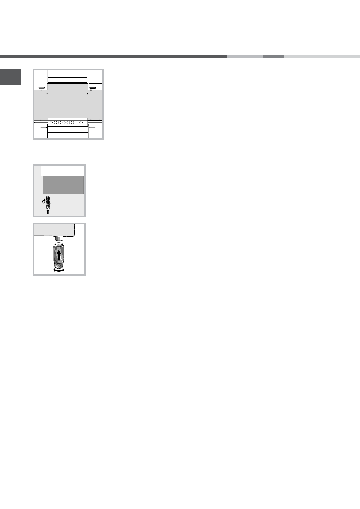
RO
HOOD
420
Min.
min.
650
mm. with hood
min.
700
mm. without hood
mm.
600
Min. mm.
420
Min. mm.
Punerea la nivel
• perdelele nu trebuie
să fi e montate în spatele
aragazului şi nici la mai
puţin de 200 mm de
fl ancurile acestuia;
• eventualele hote
trebuie să fi e instalate
conform indicaţiilor
conţinute în manualul de
instrucţiuni ale acestora.
! După instalarea aparatului, cablul de alimentare şi
priza de curent trebuie să fi e uşor accesibile.
! Cablul nu trebuie să fi e îndoit sau comprimat.
! Cablul trebuie să fi e controlat periodic şi înlocuit de
electricieni autorizaţi.
! Firma îşi declină orice responsabilitate în cazul în
care aceste norme nu se respectă.
Dacă este necesar să puneţi
la nivel aparatul, înşurubaţi
şuruburile de reglare - din
dotare – în locaşurile speciale
de sub aragaz (vezi fi gura).
Picioarele* vor fi introduse în
orifi ciile de sub aragaz.
Conectarea electrică
Montaţi pe cablu un ştecăr normalizat, capabil să suporte
sarcina indicată pe plăcuţa cu caracteristici a aparatului
(vezi tabelul cu Date tehnice).
În cazul efectuării legăturii directe la reţea, este necesar
să se monteze între aparat şi reţea un întrerupător
omnipolar cu deschiderea minimă a contactelor de 3
mm, dimensionat la sarcină, conform normelor NFC
15-100 (fi rul de împământare nu trebuie să fi e întrerupt
de întrerupător). Cablul de alimentare trebuie să fi e
poziţionat astfel încât să nu atingă în nici un punct
o temperatură cu 50°C peste temperatura mediului
ambiant.
Înainte de a efectua legătura, asiguraţivă că:
• priza să fi e cu împământare şi conform prevederilor de
lege;
• priza să poată suporta sarcina maximă de putere a
maşinii, indicată pe plăcu
• tensiunea de alimentare să fi e cuprinsă în valorile
indicate pe plăcuţa cu caracteristici;
• priza să fi e compatibilă cu ştecărul aparatului. În
caz contrar înlocuiţi priza sau ştecărul; nu folosiţi
prelungitoare sau prize multiple.
*doar pe anumite modele.
32
ţa de caracteristici;
Racordarea la gaze
Racordarea la gaze sau la butelie poate fi efectuată cu
un furtun fl exibil din cauciuc sau oţel, conform normelor
naţionale în vigoare, numai după ce aţi verifi cat că
aparatul este reglat pentru tipul de gaz pe care îl veţi
folosi (vezi eticheta de pe capac: în caz contrar vezi mai
jos). În caz de alimentare cu gaz lichefi at, de la butelie,
folosiţi regulatoare de presiune care să fi e conforme
cu normele naţionale în vigoare. Pentru a facilita
racordarea, alimentarea aragazului se poate orienta
lateral*: închideţi racordul pe care se fi xează furtunul cu
capacul respectiv şi înlocuiţi garnitura de etanşare (din
dotarea aparatului).
! Pentru o funcţionare sigură, pentru o folosire adecvată
a energiei şi o durabilitate sporită a aparaturii, asiguraţivă
că presiunea de alimentare respectă valorile indicate în
tabelul cu „Caracteristicile arzătoarelor şi duzelor” (vezi
mai jos).
Racordarea la gaze cu furtun din cauciuc
Verifi caţi ca furtunul să corespundă normelor naţionale
în vigoare. Diametrul intern al tubului de utilizat trebuie
e de: 8 mm pentru alimentarea cu gaz lichefi at şi 13
să fi
mm pentru alimentarea cu gaz metan.
După racordare, asiguraţi-vă că furtunul:
• nu atinge nici o componentă susceptibilă de a depăşi
50°C;
• nu este supus nici unui fel de forţe, de tracţiune şi de
torsiune, şi nu este curbat excesiv sau îngustat;
• nu intră în contact cu obiecte sau colţuri ascuţite,
părţi mobile şi că nu este presat;
• este uşor accesibil, pe tot traseul său, cu scopul de
al putea controla;
• are o lungime sub 1500 mm;
• este bine introdus la capete şi fi xat cu coliere de
strângere, conform normelor naţionale în vigoare.
! Dacă una sau mai multe din aceste condiţii nu sunt
respectate sau dacă aragazul este încastrat între două
Page 33

A
V
piese de mobilier – condiţii clasa a 2a, subcategoria 1 –
va trebui să utilizaţi pentru racordare un tub fl exibil din
oţel (vezi mai jos).
Racordarea la gaze cu tub fl exibil din oţel
inoxidabil, pe perete, cu cuplări fi letate
Verifi caţi ca tubul şi garniturile să corespundă normelor
naţionale în vigoare.
Pentru a monta tubul, este necesar să îndepărtaţi mufa
furtunului de pe aragaz (robinetul de alimentare cu gaz este
„tată”, de 1/2, fi letat, cilindric).
! Efectuaţi legătura astfel încât lungimea tubului să nu
depăşească 2 m (la întinderea maximă); asiguraţi-vă că
acesta nu atinge nici o componentă mobilă şi nu este
strivit.
Controlul etanşeităţii
După terminarea instalării, controlaţi perfecta
etanşeitate a tuturor racordurilor folosind o soluţie de
săpun, însă
niciodată o fl acără.
Adaptarea la diferite tipuri de gaz
Aragazul poate fi adaptat şi la alte tipuri de gaz, în afara
celui pentru care a fost predispus (indicat pe eticheta
de pe capac).
Adaptarea blatului de lucru
Înlocuirea duzelor arzătoarelor:
1. înlăturaţi grătarul şi extrageţi arzătoarele din sediul lor;
2. deşurubaţi duzele, folosind o cheie tubulară de 7 mm
(vezi fi gura), şi înlocuiţile cu cele adecvate pentru noul
tip de gaz (vezi tabelul cu “Caracteristicile arzătoarelor
şi duzelor”); .
3. montaţi la loc toate
componentele efectuând
aceleaşi operaţii ca la
demontare, dar în sens invers.
Reglarea arzătoarelor
aragazului la minim:
1. rotiţi buşonul la minim;
2. scoateţi buşonul şi rotiţi şurubul de reglare (din
interiorul sau de lângă tija centrală) până când obţineţi
o fl acără mică, constantă;
! În cazul unui gaz lichefi at, ş
să fi e înşurubat complet.
3. verifi caţi apoi ca, rotind rapid buşonul aragazului, de
la maxim la minim, să nu se stingă ochiul.
urubul de reglare trebuie
! Arzătoarele blatului nu au nevoie de reglarea aerului
primar.
Adaptarea cuptorului
Înlocuirea duzei arzătorului din cuptor:
1. scoateţi sertarul pentru încălzit alimente
2. scoateţi protecţia glisantă “A” (vezi fi gura);
3. extrageţi arzătorul cuptorului
după ce aţi scos şurubul V (vezi
fi gura);
Operaţia va fi facilitată dacă
demontaţi uşa cuptorului.
4. deşurubaţi duza arzătorului
folosind o cheie tubulară pentru
duze (vezi fi gura) sau o cheie
tubulară de 7 mm şi înlocuiţi-o
cu cea adecvată, în funcţie de
tipul de gaz (vezi tabelul cu
Caracteristicile arzătoarelor şi
duzelor).
Reglarea arzătoarelor
cuptorului la minim:
1. aprindeţi arzătorul (vezi
Pornire şi utilizare);
2. rotiţi buşonul la minim (MIN) după ce aţi lăsat arzătorul
să funcţioneze cam 10 minute la maxim (MAX);
3. scoateţi buşonul;
4. rotiţi şurubul de reglare de lângă tija termostatului
(vezi fi gurile) până când obţineţi o fl acără mică,
constantă;
! În cazul unui gaz lichefi at, şurubul de reglare trebuie
să fi e înşurubat complet;
5. verifi caţi dacă, rotind repede buşonul de la MAX
la MIN sau dacă închideţ
i şi deschideţi repede uşa
cuptorului, fl acăra rămâne aprinsă.
RO
33
Page 34

RO
S
S
R
A
DATE TEHNICE
Dimensiuni cuptor H
x L x P
Volum
Dimensiunile utile ale
sertarului de păstrare
a alimentelor la cald
Tensiunea şi
frecvenţa de
alimentare
Arzătoare
34x38x44 cm
l 57
lăţime42 cm
profunzime 44 cm
înălţime 17cm
a se vedea plăcuţa de caracteristici
se pot adapta la toate tipurile de gaz
indicate pe plăcuţa cu caracteristici,
lipită pe partea internă a uşii
rabatabile sau, după deschiderea
sertarului de sub cuptor, pe peretele
interior din stânga.
Directive Comunitare: 2006/95/EC
din 12/12/06 (Tensiune Joasă) şi
modificările succesive 2004/108/EC din 15/12/04
(Compatibilitate Electromagnetică)
şi modificările succesive 2009/142/EC din 30/11/09 (Gaze)
şi modificările succesive -93/68/CEE
din 22/07/93 şi modificările
succesive - 2002/96/EC.
1275/2008 (Stand-by/ Off mode)
Tabelul cu caracteristicile arzătoarelor şi duzelor
Tabelul 1 Gaz lichefiat Gaz natural
Arzător Diametru
Rapid (mare)
(R)
Semirapid
(mediu) (S)
Auxiliar (mic)
(A)
Cuptor - 2,80 1.0 46 80 204 200 119 267
Presiuni de
alimentare
* La 15°C 1013 mbar-gaz uscat *** Butan P.C.S. = 49,47 MJ/Kg
** Propan P.C.S. = 50,37 MJ/Kg Gaze naturale P.C.S. = 37,78 MJ/Kg
(mm)
Nominală Redusă (mm) (mm) *** ** (mm)
100 3.00 0.7 41 87 218 214 128 286
75 1.90 0.4 30 70 138 136 104 181
51 1.00 0.4 30 52 73 71 76 95
34
Putere termică
kW (p.c.s.*)
Nominală (mbar)
Minimă (mbar)
Maximă (mbar)
By Pass
1/100
duză
1/100
28-30
20
35
debit*
g/h
37
25
45
duză
1/100
20
17
25
debit*
l/h
C 34S G1 UA/HAC 34S G1 UA/HAC 34S G1 UA/HA
C 34S G3 UA /HAC 34S G3 UA /HAC 34S G3 UA /HA
Page 35

Pornire şi utilizare
F
X
C
Utilizarea aragazului
Aprinderea arzătoarelor
Fiecare buşon al aragazului are, în dreptul său, schiţa
arzătoarelor; ARZĂTORUL comandat de buşon este
reprezentat cu un cerc evidenţiat.
Pentru a aprinde un arzător al aragazului:
1. apropiaţi de arzător o fl acără sau o brichetă de aragaz;
2. apăsaţi şi, în acelaşi timp, rotiţi buşonul arzătorului
în sens contrar acelor de ceasornic, până în poziţia
maxim .
3. reglaţi intensitatea fl ăcării, după dorinţă, rotind
în sens contrar acelor de ceasornic buşonul
ARZĂTORULUI: la minim , la maxim sau într-o
poziţie intermediară.
Dacă aparatul este dotat cu
un dispozitiv electronic de
aprindere* (C), apăsaţi mai
întâi butonul de aprindere,
indicat cu simbolul
apoi apăsaţi şi rotiţi buşonul
ARZĂTORULUI în sens
contrar acelor de ceasornic,
până când reperul ajunge în dreptul poziţiei maxim;
aşteptaţi aprinderea fl ăcării.
Anumite modele sunt dotate cu un dispozitiv de
aprindere integrat în buşon; în acest caz, veţi observa
numai dispozitivul de aprindere electronic* (vezi fi gura)
dar nu şi butonul de aprindere. Este sufi cient să apăsaţi
şi, în acelaşi timp, să rotiţi buşonul ARZĂTORULUI
în sens contrar acelor de ceasornic, până în poziţia
maxim şi să aşteptaţi aprinderea fl ăcării. În momentul în
care lăsaţi buşonul, se poate întâmpla ca fl acăra să se
stingă. În acest caz, repeta
apăsat mai mult timp.
! Dacă fl acăra se stinge accidental, opriţi arzătorul şi
aşteptaţi minim 1 minut înainte să încercaţi din nou.
Dacă aparatul este dotat cu un dispozitiv de
siguranţă*(X) împotriva scăpării d e gaz, ţineţi apăsat
buşonul ARZĂTORULUI timp de 2-3- secunde, pentru a
menţine fl acăra aprinsă şi a activa dispozitivul.
Pentru a stinge arzătorul, rotiţi buşonul până la •.
ţi operaţiile, ţinând buşonul
,
Sfaturi practice pentru utilizarea arzătoarelor
Pentru a obţine un randament maxim al arzătoarelor,
precum şi a economisi gazul, utilizaţi numai recipiente
cu fundul plat, acoperite cu capac, de dimensiuni
proporţionale cu ale arzătoarelor:
Arzător Diametru
recipienţi (cm)
Rapid (R) 24-26
Semi-rapid
16-20
(S)
Auxiliar (A) 10-14
Pentru a identifi ca tipul arzătorului faceţi referire la
desenele din paragraful „Caracteristicile arzătoarelor şi
duzelor”.
Utilizarea cuptorului
! La prima aprindere, vă recomandăm să lăsaţi cuptorul
să funcţioneze în gol timp de aproximativ 1 oră, cu
termostatul la maxim şi uşa închisă. Stingeţi apoi
cuptorul, deschideţi uşa şi aerisiţi camera. Mirosul care
se degajă este datorat evaporării substanţelor utilizate
pentru a proteja cuptorul.
! Înainte de utilizare, este strict necesar să dezlipiţi folia
de plastic de pe laturile aparatului!
! Nu aşezaţi niciodată obiecte pe fundul cuptorului,
pentru că riscaţi să deterioraţi smalţul. Utilizaţi primul
nivel al cuptorului numai când folosiţi rotisorul.
Aprinderea cuptorului
Pentru a aprinde arzătorul cuptorului, apropiaţi de
orifi ciul F (vezi fi gura) o fl acără sau o brichetă şi, în
i timp, apăsaţi şi rotiţi în sens antiorar buşonul
acelaş
CUPTORULUI până la poziţia MAX.
Dacă, după 15 secunde,
arzătorul nu se aprinde,
lăsaţi buşonul, deschideţi uşa
cuptorului şi aşteptaţi cel puţin
1 minut înainte de a încerca din
nou să-l aprindeţi.
RO
! Cuptorul este dotat cu un dispozitiv de siguranţă;
ATENŢIE! Capacul din sticlă se
poate sparge dacă este încălzit.
Stingeţi toate arzătoarele sau
eventualele plite electrice înainte
de a-l închide.*Se referă numai la
modelele cu capac de sticlă
de aceea este necesar să ţineţi apăsat buşonul
CUPTORULUI timp de 6 secunde circa.
*doar pe anumite modele.
35
Page 36

RO
A
S
! Dacă fl acăra se stinge accidental, opriţi arzătorul şi
aşteptaţi minim 1 minut înainte să încercaţi din nou.
Reglarea temperaturii
Pentru a obţine temperatura ideală coacerii alimentelor,
rotiţi buşonul CUPTORULUI în sens contrar acelor de
ceasornic. Temperaturile sunt indicate pe panoul de
control şi variază de la MIN (140°C) la MAX (250°C).
După obţinerea temperaturii dorite, cuptorul o va
menţine constantă, graţie termostatului.
Grill
rotaţie aproape completă pentru a încărca soneria;
2. rotiţi buşonul TIMER în sens contrar acelor de
ceasornic pentru a regla timpul dorit.
Sertarul inferior*
Sub cuptor este un sertar care poate fi utilizat pentru
a păstra accesoriile sau vasele de bucătărie. Pentru a
deschide uşa compartimentului, rotiţi-o în jos (vezi
fi gura).
! Suprafeţele interne ale sertarului (dacă este prezent)
se pot încălzi.
Rotind în sens antiorar butonul CUPTOR până la
poziţia
infraroşii. Cu ajutorul grătarului se obţin alimente
rumenite, acesta fi ind indicat în special pentru
pregătirea rosbifului, fripturilor la cuptor, cotletelor
sau cârnaţilor. Aşezaţi grătarul la nivelul 4 sau 5
şi tava cuptorului la primul nivel, pentru a colecta
grăsimea şi a evita formarea fumului.
! Funcţionarea grătarului este semnalată prin
aprinderea indicatorului GRILL.
! Efectuaţi coacerea la grătar cu uşa cuptorului închisă,
pentru a obţine rezultate superioare şi o economie
sensibilă de energie electrică (circa 10%).
Rotisor
Pentru a pune în funcţiune rotisorul (vezi fi gura)
procedaţi astfel:
1. aşezaţi tava la primul nivel;
se pune în funcţiune grătarul cu raze
2. puneţi suportul
rotisorului la al 4lea nivel
şi introduceţi frigarea în
orifi ciul de pe peretele
din spate al cuptorului;
3. porniţi ROTISORUL
apăsând butonul
corespunzător.
! Nu depozitaţi materiale
infl amabile în sertarul de
sub cuptor.
Pe modelele de aragaz
pe gaz există o protecţie
glisantă A care serveşte
la protejarea sertarului
de sub cuptor de căldura
emanată de arzător (vezi fi gura).
Pentru a scoate protecţia
culisantă, de
(vezi fi gura). Pentru a o monta
la loc, blocaţi-o cu şurubul S.
! Înainte de a utiliza cuptorul,
verifi caţi dacă protecţia
culisantă este fi xată corect.
şurubaţi şurubul S
Becul cuptorului
Becul poate fi
BECUL CUPTORULUI.
Timer
Pentru a pune în funcţiune Timerul (Cronometrul)
procedaţi astfel:
1. rotiţi buşonul Timer în sens orar ; executaţi o
36
aprins în orice moment, apăsând tasta
*doar pe anumite modele.
Page 37
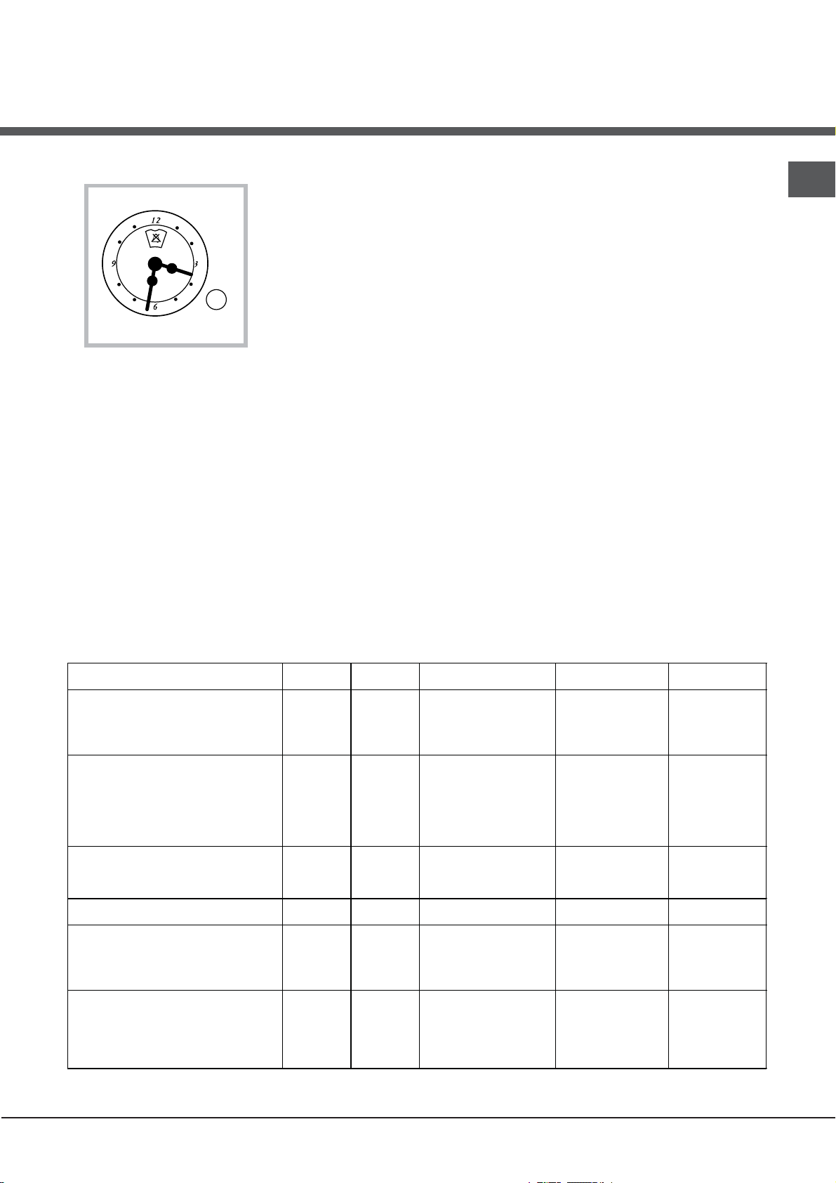
Ceas cu temporizator stil rustic*
Cum trebuie să fie resetată ora corectă
Cuptorul trebuie să fie cuplat la reţeaua de
alimentare.
Trageţi butonul şi rotiţi-l în sensul acelor de ceasornic
până în momentul în care este setată ora corectă.
! Dispozitivul de programare este alimentat electric;
prin urmare, în cazul unei căderi de tensiune, acesta
nu va funcţiona pe întreaga durată a lipsei de
alimentare cu curent electric. După această cădere
de tensiune, ora curentă trebuie să fie resetată.
Funcţia de temporizator
Funcţia de temporizator vă permite să introduceţi o
anumită perioadă de timp de la care temporizatorul
începe să efectueze numărătoarea inversă. Această
funcţie nu porneşte sau întrerupe funcţionarea
cuptorului; aceasta doar emite un semnal sonor
atunci când s-a scurs timpul.
Modul de setare a temporizatorului
Rotiţi butonul în sensul acelor de ceasornic până
când liniile marcajului se aliniază cu ora dorită (scala
internă), care poate fi vizualizată în “fereastră”.
Numărătoarea inversă a orei va începe imediat.
Pentru a întrerupe semnalul sonor al temporizatorului,
sau pentru a utiliza doar funcţia de ceas, setaţi marcajul
la simbolul
!
.
RO
Tabelul cu recomandări pt coacerea în cuptor
Alimente Greutate
Paste făinoase
Lasagne (Foi de aluat dispuse în straturi,
umplute)
Cannelloni (macaroane groase umplute)
Paste gratinate
Carne
Viţel
Pui
Raţă
Iepure
Porc
Miel
Peşte
Scrumbie
Dentex dentex
Păstrăv în folie de aluminiu
Pizza
Napoletana
Tort
Biscuiţi
Tarte
Tarte sărate
Dulciuri din aluat dospit
Gril
Cotlete de viţel
Costiţe
Hamburger
Scrumbie
Toast
(Kg)
2.5
2.5
2.5
1.5
1.5
1.8
2.0
2.1
1.8
1.1
1.5
1.0
1.0
0.5
1.1
1.0
1.0
1
1.5
1
1
4
Poziţia
rafturilor
2
2
2
3
3
3
3
3
3
3
3
3
4
4
4
4
4
4
4
3
4
4
Preîncălzire (minute) Temperatură
200-210
200
200
200-210
210-220
200
200
200
200
180-200
180-200
180-200
210-220
180
180
180
170
5
5
5
5
5
recomandată (°C)
10
10
10
10
10
10
10
10
10
10
10
10
15
15
15
15
15
Durata ciclului
(minute)
75-85
50-60
50-60
95-100
90-100
100-110
70-80
70-80
100-105
45-50
45-55
45-50
20-25
25-35
40-45
50-55
40-45
15-20
20
20-30
15-20
4-5
37
Page 38

Precauţii şi sfaturi
RO
!Aparatul a fost proiectat şi construit conform normelor
internaţionale de siguranţă.
Aceste avertizări sunt furnizate din motive de siguranţă
şi trebuie să fi e citite cu atenţie.
Norme de protecţie şi siguranţă generale
• Aceste instrucţiuni sunt valabile doar pentru
ţările ale căror simboluri apar în manualul
de instrucţiuni şi pe tăbliţa de identifi care a
aparatului.
• Acest aparat de uz casnic fost conceput pentru a fi
folosit numai în interiorul locuinţelor.
• Aparatul nu trebuie instalat în aer liber, nici chiar
în cazul în care spaţiul este adăpostit, deoarece
expunerea acestuia la ploi şi furtuni este foarte
periculoasă.
• Nu atingeţi maşina când sunteţi desculţi sau cu
mâinile sau picioarele ude sau umede.
• Aparatul trebuie sa fie utilizat numai pentru
coacerea alimentelor si numai de persoane
adulte, conform instructiunilor din manual. Orice
alta utilizare (de exemplu: încalzirea locuintei)
este considerata improprie si deci periculoasa.
Fabricantul nu va putea fi considerat responsabil
pentru eventuale daune provenite din utilizarea
improprie, gresita sau irationala a aparatului.
• Acest manual face parte din aparatele de clasa 1
(izolat) sau 2 – subcategoria 1 (fi xat între două piese
de mobilier).
• Îndepărtaţi copiii de aparat.
• Evitaţi ca şi cablurile de alimentare ale altor aparate
electrocasnice să atingă părţile încălzite ale
aparatului.
• Nu obstrucţionaţi fantele de aerisire sau de ieşire a
căldurii.
• Evitaţi să închideţi capacul din sticlă al aragazului
(numai pe anumite modele) dacă
aprinse sau calde.
• Utilizaţi întotdeauna mănuşi speciale pentru a băga
sau scoate recipientele din cuptor.
• Nu utilizaţi lichide infl amabile (alcool, benzină) în
apropierea aparatului, când acesta este în funcţiune.
arzătoarele sunt
întreţinere înainte de a fi scos ştecărul din priză.
• În caz de defecţiune, nu umblaţi în nici un caz la
mecanismele din interior şi nu încercaţi să o reparaţi
singuri. Apela
• Nu aşezaţi obiecte grele pe uşa cuptorului, când este
deschisă.
• Este interzisă utilizarea aparatului de persoanele
(inclusiv copiii) care au o redusă capacitate fi zică
sau senzorială sau mentală, precum şi de cele fără
experienţă sau care nu s-au familiarizat cu produsul,
dacă nu sunt supravegheate de un responsabil sau
dacă nu au primit în prealabil instrucţiuni asupra
modului de folosire a aparaturii.
• Nu lăsaţi copiii să se joace cu aparatul.
ţi la serviciul de asistenţă.
Scoaterea aparatului din uz
• Eliminarea ambalajelor: respectaţi normele locale, în
acest fel ambalajele vor putea fi utilizate din nou.
• Directiva Europeană 2002/96/CE cu privire la
deşeurile care provin de la aparatura electrică
sau electronică (RAEE) prevede ca aparatele
electrocasnice să nu fi e colectate împreună cu
deşeurile urbane solide, obişnuite. Aparatele
scoase din uz trebuie să fi e colectate separat atât
pentru a optimiza rata de recuperare şi de reciclare
a materialelor componente cât şi pentru a evita
pericolele care pot duce la dăunarea sănătăţii
omului sau poluarea mediului înconjurător. Simbolul
tomberonului tăiat care apare pe toate produsele vă
aminteşte tocmai obligaţia de a le colecta separat.
Aparatele electrocasnice scoase din uz pot fi trimise
unui centru public de colectare, centrelor orăşeneşti
sau, dacă legea naţională prevede, ele pot fi
returnate vânzătorului, în momentul achiziţionării
unor noi produse, echivalente.
Toţi producătorii importanţi de aparatură
electrocasnică şi-au unit eforturile pentru a crea
sisteme speciale de gestionare, care se ocupă cu
colectarea şi scoaterea din uz a aparatelor vechi.
Economisirea energiei şi protecţia
mediului înconjurător
• Utilizând aragazul între orele serale şi primele
ore ale dimineţii, colaboraţi la reducerea sarcinii
întreprinderilor electrice.
• Nu depozitaţi materiale infl amabile în sertarul de
sub cuptor: dacă cuptorul se aprinde din greşeală,
materialele depozitate pot lua foc.
• Când aparatul nu este utilizat, verifi caţi ca buşoanele
să fi e în poziţia • şi că robinetul de gaz este închis.
• Nu scoateţi ştecărul din priză trăgând de cablu.
• Nu executaţi nici o operaţie de curăţire sau
38
• Asiguraţi-vă că garniturile sunt curate, efi ciente, că
aderă bine pe uşa cuptorului şi nu provoacă
dispersii de căldură.
Page 39

Întreţinere şi curăţire
Decuplarea electrică
Înainte de orice operaţie, debranşaţi aparatul de la
reţeaua de alimentare cu curent electric.
Curăţarea aparatului
! Evitaţi utilizarea de detergenţi abrazivi sau corosivi,
ca de ex. soluţiile de scos pete sau produsele împotriva
ruginii, detergenţii praf sau bureţii care au o suprafaţă
rugoasă: ele pot zgâria iremediabil suprafaţa aparatului.
! Nu utilizaţi niciodată produse pe bază de vapori sau
cu presiune ridicată în vederea curăţării aparatelor.
• Pentru operaţiile de întreţinere curente, este sufi cient
să spălaţi aragazul cu un burete umed, după care
să-l ştergeţi cu hârtie absorbantă de bucătărie.
• Părţile externe, smălţuite sau din inox, precum şi
garniturile din cauciuc pot fi curăţate cu un burete
îmbibat în apă călduţă şi săpun neutru. Dacă petele
sunt persistente, folosiţi produse speciale. Clătiţi cu
multă ap
abrazive sau substanţe corosive.
• Grătarele, plitele de deasupra ochiurilor, coroanele
de separat fl acăra
şi arzătoarele aragazului sunt detaşabile,
pentru a facilita curăţarea lor: spălaţi-le cu apă caldă
şi detergent delicat, având grijă să scoateţi orice
depunere. Apoi aşteptaţi până când sunt perfect
uscate.
ă şi ştergeţi, după curăţire. Nu folosiţi prafuri
calcar, sau cu detergenţii agresivi (care conţin fosfor).
După fi ecare spălare, se recomandă să îl clătiţi bine şi
să îl ştergeţi. Este oportun în acelaşi timp să ştergeţi
şi eventualele urme de apă.
Capacul
Modelele dotate cu capac
din sticlă se vor spăla
cu apă călduţă. Evitaţi
substanţele abrazive.
Puteţi demonta capacul
pentru a facilita operaţiile
de curăţare, mai ales în
spatele aragazului: pentru
aceasta, deschideţi
capacul şi ridicaţi-l (vezi
fi gura).
! Evitaţi să închideţi capacul aragazului când
arzătoarele sunt calde sau aprinse.
Controlaţi garniturile cuptorului.
Controlaţi periodic garnitura din jurul uşii cuptorului.
este deteriorată, apelaţi la cel mai apropiat
Dacă
Centru de Asistenţă Autorizat. Se recomandă să nu
folosiţi cuptorul până la înlocuirea garniturii.
Întreţinerea robinetelor de gaz
Cu timpul, se poate întâmpla ca buşoanele să se
blocheze sau să se rotească mai greu; în acest caz,
este necesar să le înlocuiţi.
RO
• Dacă aparatul dvs are aprindere electronică, este
necesar să îl curăţaţi cât mai des - în special capătul
dispozitivelor de aprindere instantanee – şi să
verifi caţi dacă orifi ciile prin care iese gazul nu sunt
înfundate.
• Interiorul cuptorului se va spăla, de preferinţă, după
fi ecare utilizare, când este cald. Utilizaţi apă cald
detergent; clătiţi bine şi ştergeţi cu o lavetă moale.
Evitaţi substanţele abrazive.
• Curăţaţi geamul uşii cu un burete; nu utilizaţi produse
abrazive; ştergeţi cu o lavetă moale; nu folosiţi
articole abrazive sau răzuitoare din metal, ascuţite,
deoarece acestea pot deteriora suprafaţa geamului
sau îl pot sparge.
• Accesoriile pot fi spălate ca orice alt vas, chiar şi în
maşina de spălat vase.
• Oţelul inox poate rămâne pătat dacă intră des în
contact cu apa, mai ales dacă are un conţinut mare de
ă şi
! Această operaţie trebuie să fi e executată numai de
un instalator autorizat de fabricant.
Înlocuirea becului cuptorului
1. După ce aţi debranşat
aparatul de la alimentarea
electrică, scoateţi capacul din
sticlă care acoperă becul (vezi
fi gura).
2. Deşurubaţi becul şi înlocuiţi-l
cu unul similar: tensiune 230 V,
putere 25 W, cuplare E 14.
3. Montaţi la loc capacul de sticlă şi racordaţi din nou
aragazul la instalaţia electrică.
Asistenţă
Comunicaţi:
• modelul aparatului (Mod.);
• numărul de serie (S/N).
Aceste informaţii se găsesc pe tăbliţa cu caracteristici
lipită pe aparat şi/sau pe ambalaj.
39
Page 40

RO
12/2011- 195086623.03
XEROX FABRIANO
40
 Loading...