


Operating Instructions
COOKER AND OVEN
|
|
|
|
|
|
|
|
|
|
|
Contents |
|
GB |
|
RS |
|
|
|
|
|
Installation, 2-3 |
||
|
|
|
|
|
|
|
English, 1 |
РУССКИЙ,12 |
|||
|
Positioning and levelling |
||||
|
|
|
|
|
Electrical connections |
|
|
|
|
|
Technical data |
|
Description of the appliance, 4 |
|
|
Overall view |
|
|
Control panel |
|
|
Start-up and use, 5-8 |
|
|
Starting the oven |
|
|
Cooking modes |
|
|
Electronic timer |
|
|
Oven cooking advice table |
|
C3VM57RU /HA |
Using the glass ceramic hob, 9 |
|
Switching the cooking zones on and off |
||
|
||
|
Cooking zones |
|
|
Precautions and tips, 10 |
|
|
General safety |
|
|
Disposal |
|
|
Respecting and conserving the environment |
|
|
Care and maintenance, 11 |
|
|
Switching the appliance off |
|
|
Cleaning the oven |
|
|
Replacing the oven light bulb |
|
|
Cleaning the glass ceramic hob |
|
|
Assistance |

Installation
|
! Before operating your new appliance please read |
|
|
this instruction booklet carefully. It contains |
|
GB |
||
important information concerning the safe installation |
||
|
and operation of the appliance. |
|
|
||
|
! Please keep these operating instructions for future |
|
|
reference. Make sure that the instructions are kept |
|
|
with the appliance if it is sold, given away or moved. |
|
|
! The appliance must be installed by a qualified |
|
|
professional according to the instructions provided. |
|
|
! Any necessary adjustment or maintenance must be |
|
|
performed after the appliance has been |
|
|
disconnected from the electricity supply. |
|
|
We recommend cleaning the oven before |
|
|
using it for the first time, following the |
|
|
instructions provided in the "Care and |
|
|
maintenance" section. |
Positioning and levelling
cupboards whose height does not exceed that of the ! It is possible to install the appliance alongside
hob surface.
! Make sure that the wall in contact with the back of the appliance is made from a non-flammable, heatresistant material (T 90°C).
• Place it in the kitchen, the dining room or the bedTo install the appliance correctly:
cupboards,
sit (not in the bathroom).
• If the top of the hob is higher than the
the appliance must be installed at least 200 mm
away from them. |
installed underneath a wall |
|
• If the cooker is |
|
HOOD |
|
|
|
cabinet, there must be a |
|
|
|
|
|
||
Min. 600mm. |
|
|
|
mm between this cabinet |
|
|
min. 650 mm. with hood |
min. 700 mm. without hood |
minimum distance of 420 |
||
Min. 420mm. |
Min. 420mm. |
This distance should be |
|||
and the top of the hob. |
|||||
increased to 700 mm if |
|||||
|
|
|
|
||
|
|
|
|
the wall cabinets are |
|
|
|
|
|
flammable (see figure). |
•Do not position blinds behind the cooker or less
than 200 mm away from its sides.
instructions listed in the relevant operating manual.
•Any hoods must be installed according to the
Levelling
If it is necessary to level the appliance, screw the adjustable feet* into the places provided on each corner of the base of the cooker (see figure).
The legs* provided with the appliance fit into the slots on the underside of the base of the cooker.
Electrical connections
Fitting the power supply cable
The cable should be suited to the type of electrical connection used, according to the following connection diagram:
400 3N |
1 |
|
2 |
|
3 |
4 |
5 |
|
|||||
H05RR-F 5x2.5 CEI-UNEL 35363 R |
|
|
|
S |
T |
|
|
|
|
N |
|||
|
|
|
|
|
|
|
|||||||
H05VV-F 5x2.5 CEI-UNEL 35746 |
1 |
|
|
|
|
|
3 |
4 |
5 |
|
|||
400V 2N |
|
|
2 |
|
|
||||||||
|
|
|
|
|
|
|
|
|
|
|
|
|
|
H05RR-F 4x4 CEI-UNEL 35363 |
|
|
|
|
|
|
R |
S |
|
|
N |
|
|
H05VV-F 4x4 CEI-UNEL 35746 |
|
|
|
|
|
|
|
|
|
|
|
|
|
|
|
|
|
2 |
|
3 |
|
4 |
5 |
||||
230V |
1 |
|
|
||||||||||
|
|
|
|
|
|
|
|||||||
H05RR-F 3x4 CEI-UNEL 35363 |
|
R |
|
|
|
|
|
|
|
N |
|
|
|
|
|
|
|
|
|
|
|
|
|
||||
H05VV-F 3x4 CEI-UNEL 35746 |
|
|
|
|
|
|
|
|
|
|
|
|
|
To install the power supply cable correctly:
V |
1. Loosen the screw V in the terminal board and pull the cover to open it (see figure).
2 |
3 |
1 |
|
|
B |
N |
A |
|
2. Position the connection support A (see figure) according to the connection diagram shown above. The terminal board is designed for singlephase 230 V connection: terminals 1, 2 and 3 are connected to each other; jumper 4-5 is located in the
lower area of the terminal board.
3.Position wires N and 6 according to the diagram (see figure) and perform the connection by tightening the terminal board screws as much as possible.
4.Position the remaining wires on terminals 1-2-3 and tighten the screws.
2
5.Fix the power supply cable in place by fastening the cable clamp screw.
6.Close the terminal board cover by tightening the screws V.
Connecting the supply cable to the mains
Install a standardised plug corresponding to the load indicated on the data plate located on the appliance.
The appliance must be directly connected to the mains using an omnipolar circuit-breaker with a minimum contact opening of 3 mm installed between the appliance and the mains. The circuit-breaker must be suitable for the charge indicated and must comply with current electrical regulations (the earthing wire must not be interrupted by the circuitbreaker). The supply cable must be positioned so that it does not come into contact with temperatures higher than 50°C at any point.
Before connecting the appliance to the power supply, make sure that:
•The appliance is earthed and the plug is compliant with the law.
•The socket can withstand the maximum power of the appliance, which is indicated by the data plate.
•The voltage is in the range between the values indicated on the data plate.
•The socket is compatible with the plug of the appliance. If the socket is incompatible with the plug, ask an authorised technician to replace it. Do not use extension cords or multiple sockets.
!Once the appliance has been installed, the power supply cable and the electrical socket must be easily accessible.
!The cable must not be bent or compressed.
!The cable must be checked regularly and replaced by authorised technicians only.
!The manufacturer declines any liability should these safety measures not be observed.
TECHNICAL DATA |
GB |
|
|
||
Oven dimensions |
34x38x41 cm |
|
(HxWxD) |
||
|
||
Volume |
53 l |
|
Useful |
width 42 cm |
|
measurements |
||
depth 44 cm |
||
relating to the oven |
||
height 17 cm |
||
compartment |
||
|
||
Power supply |
see data plate |
|
voltage and |
||
frequency |
|
|
Ceramic hob |
|
|
Front Left |
1200 W |
|
Back Left |
1800 W |
|
Back Right |
1200 W |
|
Front Right |
1800 W |
|
Max. ceramic hob |
|
|
consumption |
6000 W |
|
|
Directive 2002/40/EC on the label of |
|
|
electric ovens. Standard EN 50304 |
|
|
Energy consumption for Natural |
|
ENERGY LABEL |
convection – heating mode: Static; |
|
|
||
|
Declared energy consumption for |
|
|
Forced convection Class – heating |
|
|
mode: Fan-assisted. |
|
|
EC Directives: 06/95/EC dated 12/12/06 |
|
|
(Low Voltage) and subsequent |
|
|
amendments – |
|
|
04/108/EC dated 15/12/04 |
|
|
(Electromagnetic Compatibility) and |
|
|
subsequent amendments – |
|
|
93/68/EEC dated 22/07/93 and |
|
|
subsequent amendments – |
|
|
2002/96/EC. |
|
|
1275/2008 Stand-by/ Off mode |
*Only available in certain models.
3
Description of the appliance
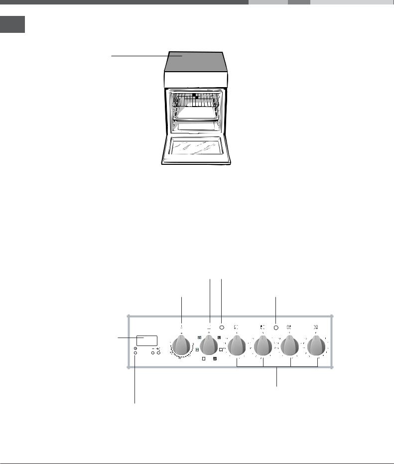
Overall view
GB
Glass ceramic hob
Control panel |
|
|
|
|
|
|
|
|
|
|
|
|
|
GUIDE RAILS |
|
|
|
|
|
|
|
||||||||
|
|
|
|
|
|
|
|
|
|
|
|
|
|
for the sliding racks |
GRILL rack |
|
|
|
|
|
|
|
|
|
|
|
|
position 5 |
|
|
|
|
|
|
|
|
|
|
|
|
position 4 |
|||
|
|
|
|
|
|
|
|
|
|
|
|
|||
DRIPPING PAN |
|
|
|
|
|
|
|
|
|
|
|
|
position 3 |
|
|
|
|
|
|
|
|
|
|
|
|
|
|||
|
|
|
|
|
|
|
|
|
|
position 2 |
||||
|
|
|
|
|
|
|
|
|
|
|
|
|
|
|
Adjustable foot |
|
|
|
|
|
|
|
|
|
|
|
position 1 |
||
|
|
|
|
|
|
|
|
|
|
|
||||
|
|
|
|
|
|
|
|
|
Adjustable foot |
|||||
|
|
|
|
|
|
|
|
|
|
|
||||
|
|
|
|
|
|
|
|
|
|
|
|
|
|
|
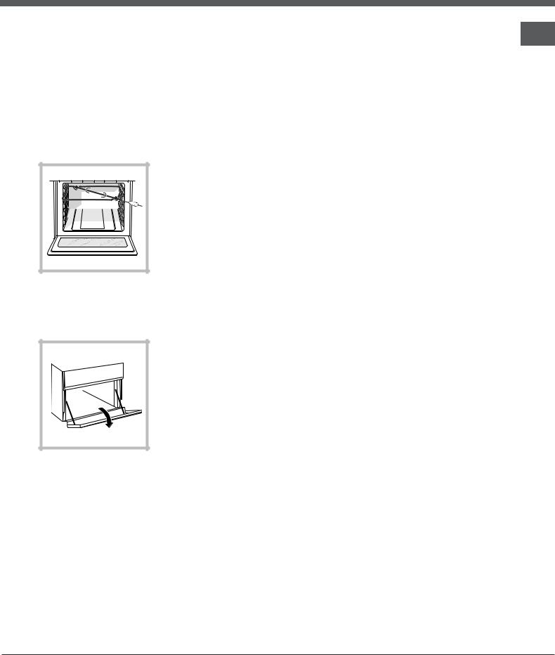
Control panel
SELECTOR |
THERMOSTAT |
knob |
indicator light |
THERMOSTAT |
ACTIVE HOTPLATE |
knob |
indicator light |
Electronic |
|
timer |
|
|
HALOGEN |
|
hotplate knobs |
TIMER |
|
button |
|
4

Start-up and use
!The first time you use your appliance, heat the empty oven with its door closed at its maximum temperature for at least half an hour. Ensure that the room is well ventilated before switching the oven off and opening the oven door. The appliance may emit a slightly unpleasant odour caused by protective substances used during the manufacturing process burning away.
!Before operating the product, remove all plastic film from the sides of the appliance.
Starting the oven
1.Select the desired cooking mode by turning the SELECTOR knob.
2.Select the recommended temperature for the cooking mode or the desired temperature by turning the THERMOSTAT knob.
A list detailing cooking modes and suggested cooking temperatures can be found in the relevant table (see Oven cooking advice table).
During cooking it is always possible to:
•Change the cooking mode by turning the SELECTOR knob.
•Change the temperature by turning the THERMOSTAT knob.
•Set the total cooking time and the cooking end time (see below).
•Stop cooking by turning the SELECTOR knob to the “0” position.
!Never put objects directly on the bottom of the oven; this will avoid the enamel coating being damaged. Only use position 1 in the oven when cooking with the rotisserie spit.
!Always place cookware on the rack(s) provided.
THERMOSTAT indicator light
GB
When this is illuminated, the oven is generating heat. It switches off when the inside of the oven reaches the selected temperature. At this point the light illuminates and switches off alternately, indicating that the thermostat is working and is maintaining the temperature at a constant level.
Oven light
This is switched on by turning the SELECTOR knob to any position other than “0”. It remains lit as long as the oven is operating. By selecting 8 with the knob, the light is switched on without any of the heating elements being activated.
5

Cooking modes
GB
! A temperature value can be set for all cooking modes between 50°C and Max, except for the following modes
•GRILL and DOUBLE GRILL (recommended: set only to MAX power level).
•FAN-ASSISTED DOUBLE GRILL (recommended: do not exceed 200°C).
aSTATIC OVEN mode
Both the top and bottom heating elements will be activated. When using this traditional cooking mode, it is best to use only one rack at a time, otherwise the heat will not be distributed evenly.
bFAN OVEN mode
The top and bottom heating elements will switch on and the fan will begin to operate. Since the heat remains constant throughout the oven, the air cooks and browns food in a uniform manner. A maximum of two racks may be used at the same time.
cGRILL mode
The central part of the top heating element is switched on. The high and direct temperature of the grill is recommended for food that requires a high surface temperature (veal and beef steaks, fillet steak and entrecôte). This cooking mode uses a limited amount of energy and is ideal for grilling small dishes. Place the food in the centre of the rack, as it will not be cooked properly if it is placed in the corners.
2DOUBLE GRILL mode
The top heating element and the rotisserie spit will be activated.
This provides a larger grill than the normal grill setting and has an innovative design that improves cooking efficiency by 50% and eliminates the cooler corner areas. Use this grilling mode to achieve a uniform browning on top of the food.
TDOUBLE GRILL mode
The top heating element and the turnspit are activated and the fan begins to operate. This combination of features increases the effectiveness of the unidirectional thermal radiation of the heating
elements through forced circulation of the air throughout the oven. This prevents the food from burning on top by enabling heat to penetrate into the food more effectively; it is therefore an ideal way of cooking food quickly under the grill or for grilling large pieces of meat without having to use the turnspit.
!The GRILL, DOUBLE GRILL and FAN-ASSISTED DOUBLE GRILL cooking modes must be performed with the oven door shut.
!When using the GRILL and DOUBLE GRILL cooking modes, place the rack in position 5 and the dripping pan in position 1 to collect cooking residues (fat and/or grease). When using the FAN-ASSISTED DOUBLE GRILL cooking mode, place the rack in position 2 or 3 and the dripping pan in position 1 to collect cooking residues.
Electronic timer
This function displays the time and works as a timer which counts down to zero.
! All functions will be implemented approximately 7 seconds after they have been set.
Resetting the clock
After the appliance has been connected to the power supply, or after a power cut, the clock display will begin to blink, showing the figure: 0:00
•Press button G and then buttons - and + to set the exact time. Press and hold the buttons to
quicken the count upwards.
Any necessary modifications can be made by repeating the above process.
Timer feature
This function may be accessed by pressing the n button, after which the display will show the symbol n. Every time the + button is pressed it corresponds
to a time increase of 10 seconds, until it reaches 99 minutes and 50 seconds. After this point, each press of the button represents an increase of one minute, up to a maximum of 10 hours.
Pressing the - button reduces the time.
After the time period has been set, the timer will begin to count down. When the timer reaches zero, the buzzer will sound (this may be stopped by pressing any button).
The time may be displayed by pressing the G
button, and the n symbol indicates that the timer
function has been set. After approximately 7 seconds, the display will automatically revert to the timer.
6
Cancelling a time that has already been set
Press the – button until the display shows 0:00.
Adjusting the buzzer volume
After selecting and confirming the clock settings, use the – button to adjust the volume of the alarm buzzer.
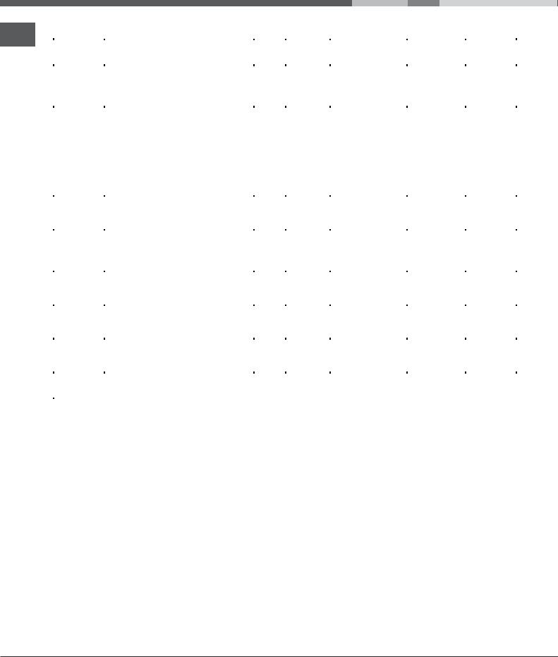
Rotisserie
To operate the rotisserie (see diagram)
proceed as follows:
1. Place the dripping
pan in position 1.
2. Place the rotisserie support in position 4 and insert the spit in
the hole provided on the back panel of the oven.
3. Activate the rotisserie by selecting 2 or T with the SELECTOR knob.
Lower compartment*
There is a compartment underneath the oven that may be used to store oven accessories or deep dishes. To open the door pull it downwards (see figure).
!Do not place flammable materials in the lower oven compartment.
!The internal surfaces of the compartment (where present) may become hot.
Cooking on several shelves simultaneously
GB
If it is necessary to use two racks, use the FAN OVEN cooking mode b, as this is the only cooking mode suited to this type of cooking. We also recommend that:
•Positions 1 and 5 are not used. This is because excessive direct heat can burn temperature sensitive foods.
•Positions 2 and 4 are used and that food that requires more heat is placed on the rack in position 2.
•When cooking foods that require different cooking times and temperatures, set a temperature that is halfway between the two recommended temperatures (see Oven cooking advice table) and place the more delicate food on the rack in position 4. Remove the food that requires a shorter cooking time first.
•When cooking pizzas on several racks with the temperature set to 220°C, the oven is preheated for 15 minutes. Generally speaking, cooking on the rack in position 4 takes longer: we recommend that the pizza cooked on the lowest rack position is removed first, followed by the pizza cooked in position 4 a few minutes later.
•Place the dripping pan on the bottom and the rack on top.
*Only available in certain models.
7
Oven cooking advice table
GB
Cooking |
Foods |
Weight |
Rack |
Preheating time |
Recommended |
Cooking |
|
modes |
Temperature |
time |
|||||
(in kg) |
position |
(min) |
|||||
|
|
(°C) |
(minutes) |
||||
|
|
|
|
|
|||
|
Duck |
1 |
3 |
15 |
200 |
65-75 |
|
Static |
Roast veal or beef |
1 |
3 |
15 |
200 |
70-75 |
|
Roast pork |
1 |
3 |
15 |
200 |
70-80 |
||
|
Biscuits (shortcrust pastry) |
- |
3 |
15 |
180 |
15-20 |
|
|
Tarts |
1 |
3 |
15 |
180 |
30-35 |
|
|
Pizza (on 2 racks) |
1 |
2 and 4 |
15 |
230 |
15-20 |
|
|
Lasagne |
1 |
3 |
10 |
180 |
30-35 |
|
|
Lamb |
1 |
2 |
10 |
180 |
40-45 |
|
|
Roast chicken + potatoes |
1+1 |
2 and 4 |
15 |
200 |
60-70 |
|
Fan-assisted |
Mackerel |
1 |
2 |
10 |
180 |
30-35 |
|
Sponge cake made with yoghurt |
1 |
2 |
10 |
170 |
40-50 |
||
|
Cream puffs (on 2 racks) |
0.5 |
2 and 4 |
10 |
190 |
20-25 |
|
|
Biscuits (on 2 racks) |
0.5 |
2 and 4 |
10 |
180 |
10-15 |
|
|
Sponge cake (on 1 rack) |
0.5 |
2 |
10 |
170 |
15-20 |
|
|
Sponge cake (on 2 racks) |
1 |
2 and 4 |
10 |
170 |
20-25 |
|
|
Savoury pies |
1.5 |
3 |
15 |
200 |
25-30 |
|
|
Sole and cuttlefish |
1 |
4 |
5 |
Max |
8-10 |
|
Grill |
Squid and prawn kebabs |
1 |
4 |
5 |
Max |
6-8 |
|
Cod fillet |
1 |
4 |
5 |
Max |
10 |
||
|
|||||||
|
Grilled vegetables |
1 |
3/4 |
5 |
Max |
10-15 |
|
|
Veal steak |
1 |
4 |
5 |
Max |
15-20 |
|
|
Cutlets |
1 |
4 |
5 |
Max |
15-20 |
|
|
Hamburgers |
1 |
4 |
5 |
Max |
7-10 |
|
|
Mackerel |
1 |
4 |
5 |
Max |
15-20 |
|
Double Grill |
Toast |
4 pcs |
4 |
5 |
Max |
2-3 |
|
|
With the rotisserie |
1.0 |
- |
5 |
Max |
80-90 |
|
|
Spit-roast veal |
||||||
|
Spit-roast chicken |
1.5 |
- |
5 |
Max |
70-80 |
|
|
Spit-roast lamb |
1.0 |
- |
5 |
Max |
70-80 |
|
|
Grilled chicken |
1.5 |
2 |
5 |
200 |
55-60 |
|
|
Cuttlefish |
1.5 |
2 |
5 |
200 |
30-35 |
|
|
Chicken (on the spit) + |
1.5 |
- |
5 |
200 |
70-75 |
|
|
potatoes (on the dripping pan) |
- |
2 |
5 |
200 |
70-75 |
|
Fan-assisted |
With the rotisserie |
1.5 |
- |
5 |
200 |
70-80 |
|
Double Grill |
Spit-roast veal |
||||||
Spit-roast chicken |
1.5 |
- |
5 |
200 |
70-80 |
||
|
|||||||
|
Spit-roast lamb |
1.5 |
- |
5 |
200 |
70-80 |
|
|
With multi-spit rotisserie (where present) |
|
|
|
|
|
|
|
Meat kebabs |
1.0 |
- |
5 |
200 |
40-45 |
|
|
Vegetable kebabs |
0.8 |
- |
5 |
200 |
25-30 |
8
 Loading...