

Page 1
PIANI COTTURA (type PL73 e PL74)
ISTRUZIONI PER L’USO
Grafica RB - 02-2007 - Cod. 41017812 - Imprimè en Italie
HOOVER - Via Privata Eden Fumagalli - 20047 Brugherio (Milano) - Italy
IT
HOBS (type PL73 e PL74)
USER INSTRUCTION
GB IE
PLACAS (type PL73 e PL74)
INSTRUÇÕES DE UTILIZAÇÃO
KOOKPLATEN (type PL73 e PL74)
GEBRUIKSAANWIJZING
PT
NL
Page 2

2
ISTRUZIONI PER L’INSTALLATORE
INSTALLAZIONE
L’installazione è a carico dell’acquirente. La Casa Costruttrice è esonerata da questo
servizio. Gli eventuali interventi richiesti alla Casa Costruttrice, se dipendono da un’errata installazione, non sono compresi nella garanzia.
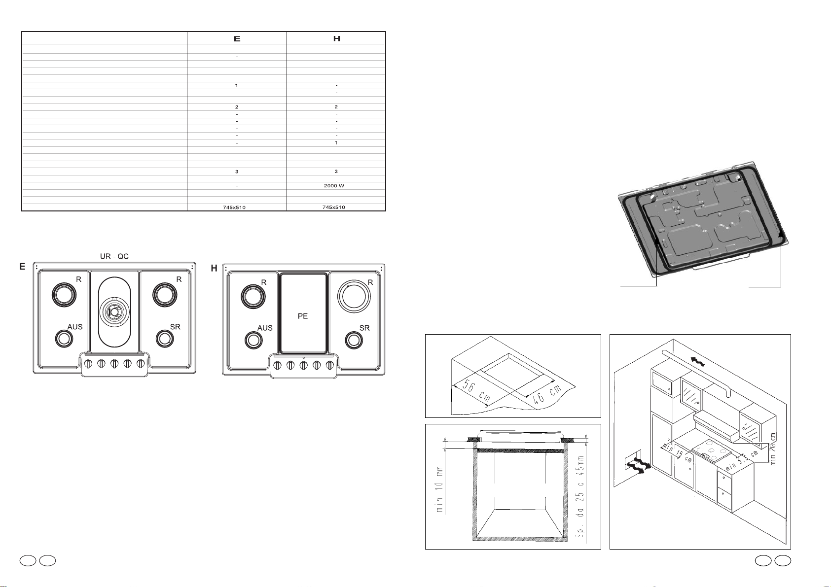
I piani da incasso sono predisposti per l’installazione in tops realizzati in qualsiasi materiale, purché resistente ad una temperatura di 100° C, e di spessore variabile fra 25 e
45 mm. Le dimensioni del foro per l’incasso devono rispettare le misure riportate in figura 1.
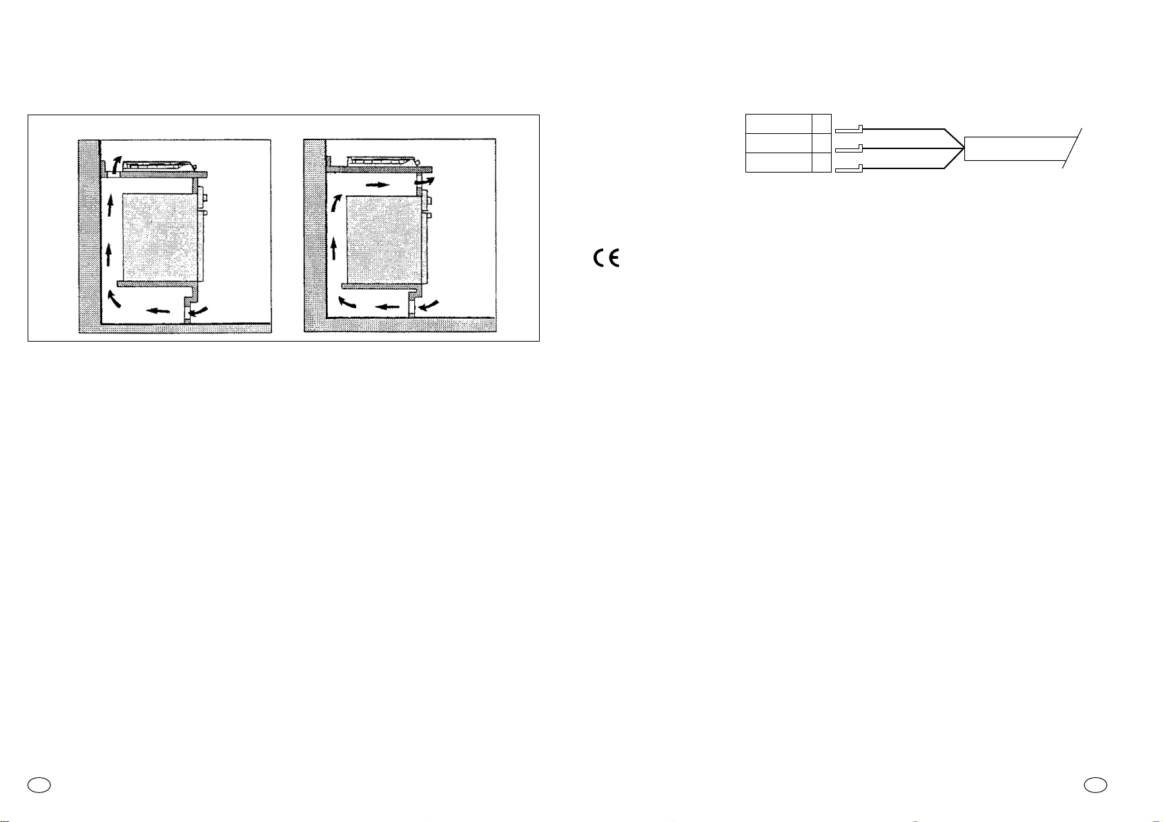
Qualora il piano venga incassato in modo che sul suo lato sinistro o destro ci
sia la parete di un mobile, la distanza tra la parete verticale ed il bordo del piano,
deve essere di almeno 15 cm (fig. 2); la distanza tra la parete posteriore ed il bordo
del piano deve essere di almeno 5,5 cm (fig. 2); la distanza tra il piano cottura ed
un’eventuale elemento superiore (es. cappa) deve essere di almeno 70 cm (fig. 2).
Quando sotto il piano è presente un vano
accessibile, fra il piano da incasso ed il vano sottostante, deve essere inserita una
parete di divisione in materiale isolante (legno o similari).
Tale parete deve avere le dimensioni pari
al modulo da incasso e deve distare almeno 10 mm dal fondo della cassetta (fig. 3).
IMPORTATE: La figura qui a fianco indica come deve essere applicato il sigillante.
Il fissaggio al mobile è ottenuto tramite staffe di fissaggio che vengono fornite come
accessori. Nella parte inferiore della cassetta sono presenti i fori a cui devono essere
avvitate le staffe di fissaggio.
IT
Fig. 1
Fig. 2
Fig. 3
Plan 60 Plan 75
Bruciatore ausiliario ø 50mm
Bruciatore ultra rapido UR ø 110 mm
Bruciatore semirapido SR ø 75 mm
Bruciatore rapido R ø 100 mm
Piastra elettrica ø80 PE
Piastra elettrica ø145 PE
Piastra elettrica 160x265 mm PE
G20 20mbar* (METANO)
Tensione/Frequenza V/Hz
PIANI COTTURA
Fuochi
Referimento di tipo Type
Dispositivo di sicurezza gas
Bruciatore doppia corona QC ø 135 mm
Bistecchiera 174x160 mm
Bistecchiera 229x379
Potenza gas installata:
G30 28-30mbar (GPL)
Classe d'installazione
Potenza elettrica installata:
Accensione elettronica
Dimensione del prodotto l x p (mm)
5 a gas
4 a gas
1 electr.
- / si
- / si
si
si
PL 73/PL 74
PL 73/PL 74
1
1
1
1
1
11,25 kW
7,75 kW
818 g/h
636 g/h
220-240/50
220-240/50
1
* Predisposizione di fabbrica IT cat. II2H3 +
Tab. 1
Questo apparecchio è stato concepito per un uso non professionale all’interno
delle abitazioni.
IT
Page 3
4
Se il cavo di alimentazione è danneggiato, esso deve essere sostituito dal costruttore
o dal suo servizio assistenza tecnica o comunque da una persona con qualifica similare, in modo da prevenire ogni rischio. Il conduttore di terra (giallo-verde) deve essere
obbligatoriamente più lungo di 10 mm. La sezione dei conduttori interni deve essere
appropriata alla potenza assorbita dal piano cottura (vedi etichetta) ed il tipo di cavo
deve essere H05RR-F , H05VV-F, H05V2V2-F.
Dichiarazione di conformità. Questa apparecchiatura, nelle parti destinate a venire
a contatto con sostanze alimentari, è conforme alla prescrizione della dir. CEE 89/109
e al D.L. di attuazione N° 108 del 25/01/92.
Apparecchio conforme alle direttive europee 89/336/CEE, 90/396/CEE, 73/23/CEE
e successive modifiche.
LINEA L
TERRA
NEUTRO N
RETE DI
ALIMENTAZIONE
ELETTRICA
MARRONE
GIALLO/VERDE
BLU
CAVO DI
ALIMENTAZIONE
Le istruzioni sono rivolte al personale autorizzato all’installazione dell’apparecchio in
conformità alle norme UNI-CIG 7129-7131. Qualsiasi intervento deve essere eseguito con apparecchiatura disinserita elettricamente.
Sul piano di lavoro è indicato, con apposite targhette, il tipo di gas per il quale l’apparecchio è predisposto.
È tuttavia possibile usare altri tipi di gas dopo aver eseguito dei semplici adattamenti.
(Vedere indicazioni paragrafi seguenti)
ll collegamento dell’apparecchio alla tubazione o alla bombola del gas dovrà essere effettuato come prescritto dalle Norme UNI-CIG 7129 e 7131, solo dopo essersi accertati
che esso è regolato per il tipo di gas con cui sarà alimentato. In caso contrario eseguire
le operazioni indicate al paragrafo «Adattamento ai diversi tipi di gas». Nel caso di alimentazione con gas liquido da bombola, utilizzare regolatori di pressione conformi alle
Norme UNI-CIG 7432.
Importante: per un sicuro funzionamento, per un adeguato uso dell’energia e maggiore
durata dell’apparecchiatura, assicurarsi che la pressione di alimentazione rispetti i valori
indicati nella tabella consumi gas.
Utilizzare esclusivamente tubi conformi alla Norma UNI-CIG 9891 e guarnizioni di tenuta conformi alla norma EN549.
La messa in opera dei tubi flessibili deve essere effettuata in modo che la loro lunghezza, in condizioni di massima estensione, non sia maggiore di 2 m.
IMPORTANTE : ad installazione ultimata controllare la PERFETTA TENUTA di tutti i raccordi utilizzando una soluzione saponosa e MAI UNA FIAMMA. Assicurarsi
inoltre, che il tubo flessibile non possa essere a contatto con una parte mobile
del modulo da incasso (es. cassetto) e che non sia situato in luoghi dove possa
essere danneggiato.
ALLACCIAMENTO ALLA RETE GAS
IT
3
LOCALE DI INSTALLAZIONE
L’utilizzo di un apparecchio di cottura a gas produce calore e umidità nel locale in cui
è installato. Vogliate assicurare una buona areazione del locale mantenendo aperti gli
orifizi di ventilazione naturale o installando una cappa di aspirazione con condotto di
scarico (Fig. 2). Un utilizzo intensivo e prolungato dell’apparecchio può necessitare di
una areazione supplementare per esempio l’apertura di una finestra o un’areazione
più efficace aumentando la potenza di aspirazione meccanica se essa esiste. Nel caso in cui l’apparecchio fosse sprovvisto di termocoppia (dispositivo di sicurezza) la
presa di ventilazione di fig. 2 dovrà essere di 200 cm
2
minimo.
In caso non sia possibile installare la cappa è necessario l’impiego di un elettroventilatore applicato alla parete esterna o alla finestra dell’ambiente purché esistano nel locale le aperture per l’entrata di aria.
Questo elettroventilatore deve avere una portata tale da garantire, per un ambiente
cucina un ricambio orario d’aria di 3-5 volte il suo volume.
L’installatore deve attenersi alle norme in vigore: UNI-CIG 7129 e 7131.
Se sotto al piano cottura da 60 cm. è installato un forno senza ventilatore di raffreddamento è necessario praticare delle aperture nel modulo da incasso per garantire
una corretta circolazione dell’aria. Tali aperture devono garantire una superficie libera di almeno 300 cm2ripartiti come mostrato nella figura 4.
Sotto al piano di cottura da 75 cm. può essere installato solo un forno fornito di un
ventilatore di raffreddamento.
ALLACCIAMENTO ALLA RETE ELETTRICA
Controllare i dati riportati sulla targhetta dell’apparecchio, ubicata sulla parte inferiore
esterna della cassetta, quindi accertarsi che tensione nominale di rete e potenza disponibili, siano adatte al suo funzionamento.
Prima di effettuare il collegamento verificare l’efficienza dell’impianto di messa a terra.
La messa a terra dell’apparecchio è obbligatoria per Legge. La Casa Costruttrice declina ogni responsabilità per eventuali danni a persone o a cose derivanti dalla mancata
osservanza di questa norma.
Per eventuali modelli sprovvisti di spina, montare sul cavo una spina normalizzata che
sia in grado di sopportare il carico indicato in targhetta. Il conduttore di terra del cavo è
contraddistinto dai colori giallo verde. In ogni caso la spina deve essere accessibile.
Nel caso si desideri una connessione fissa alla rete, si dovrà interporre, tra l’apparecchio e la rete, un dispositivo omnipolare di interruzione con distanza dei contatti di almeno 3 mm.
IT
FIGURA 4
60 Cm
2
240 Cm
2
120 Cm
2
180 Cm
2
Page 4
REGOLAZIONE DEL MINIMO DELLA FIAMMA
Dopo aver sostituito l’iniettore è necessario effettuare la regolazione della fiamma.
Accendere i bruciatori portando il rubinetto in posizione di minimo e sfilare la manopola (estraibile in quanto montata a pressione).
Con un piccolo cacciavite agire sulla vite di regolazione del rubinetto (fig. 7) in senso
antiorario per aumentare la portata del gas, in senso orario per diminuirla fino ad ottenere una fiamma lunga 3 o 4 mm.
Per l’impiego di gas GPL (in bombola) la vite di regolazione del minimo deve essere avvitata (senso orario) a fine corsa.
Vite di regolazione minimo rubinetto (in funzione dei diversi modelli)
6
Fig. 7
Una volta effettuata la nuova regolazione gas sostituire sulla cassetta del vostro apparecchio la vecchia etichetta di taratura con quella corrispondente al nuovo gas.
L’etichetta è data in dotazione.
ISTRUZIONI PER L’UTENTE
USO DEL PIANO COTTURA
Questo apparecchio dovrà essere destinato solo all’uso per il quale è stato concepito,
e cioè per la cottura ad uso domestico. Ogni altro uso è da considerarsi improprio e
quindi pericoloso.
Il costruttore non può essere considerato responsabile per eventuali danni derivati da
usi impropri, erronei ed irragionevoli.
IT
Tabella consumi GAS 1 W 0,86 Kcal/h
Bruciatore in
funzione
Ausiliario
Semi rapido
Rapido
Ultra-rapido
Quadrupla corona
G20
G25
ø Ugello
1/100 mm
G30
G31
ø Ugello
1/100 mm
GZ 350
ø Ugello
1/100 mm
G20 20mbar G30 28-30mbar
G31 37mbar GZ350 13mbar
Qn
kW
QminWl/h
G20
l/h
GZ350
g/h
G30
g/h
G31
G20 25mbar
G30 36mbar
G25 25mbar
G31 30mbar
Qn
kW
QminWl/h
G20
g/h
G30
Qn
kW
QminWl/h
G25
g/h
G31
76
101
118
144
141
50
66
80
94
96
104
132
160
190
191
1
1,75
2,5
3,5
3,5
230
360
530
700
1750
95
167
238
333
333
132
232
331
463
463
73
127
182
254
254
71
125
179
250
250
1,2
2
2,8
4
4
260
410
620
830
1900
114
190
267
381
381
87
145
204
291
291
0,9
1,6
2,25
3,2
3,2
230
360
530
700
1750
100
177
255
354
354
64
114
161
229
229
CILINDRICO
CONICO
5
ADATTAMENTO AI DIVERSI TIPI DI GAS
Per adattare il piano ad un tipo di gas diverso da quello per il quale è predisposto eseguire nell’ordine le seguenti operazioni:
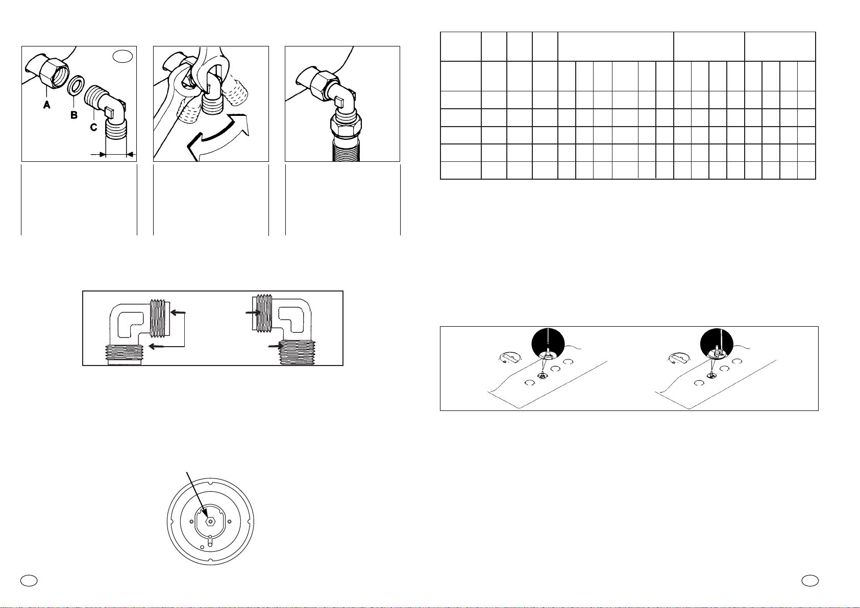
— asportare la griglia ed il bruciatore
—
introdurre una chiave esagonale a tubo (7 mm) dentro il supporto bruciatore (fig. 6).
— svitare l’iniettore e sostituirlo con quello adatto al tipo di gas disponibile, vedere ta-
bella consumi gas
1/2 GAS
CILINDRICO
1) Avvitare le parti nella
sequenza illustrata
A) Tubazione rampa
B) Guarnizione
C) Raccordo orientabile
2) Serrare forte i raccordi utilizzando le chiavi
esagonali tenendo presente, durante il serrag
gio, di orientare il
raccor
do nella direzione
desiderata.
3) Collegare il raccordo C
alla rete di alimentazione
gas tramite tubazione rigida in rame o flessiblle
in acciaio.
IT
Per non provocare sollecitazioni all’apparecchio si consiglia di eseguire l’allacciamento all’impianto nella sequenza indicata:
Fig. 6
Fig. 5
IT
INIETTORE
Per alcuni modelli si fornisce a corredo un raccordo conico per la installazione nei
paesi dove questo tipo di raccordo è obbligatorio (Gran Bretagna, Olanda,
Germania,...); nelle figure seguenti viene indicato come riconoscere i diversi tipi di
raccordi. In ogni caso la parte cilindrica del raccordo deve essere collegata al piano
cottura.
Page 5
8
MANUTENZIONE E PULIZIA
Prima di effettuare qualsiasi operazione si deve staccare la spina dalla presa di corrente o togliere la corrente a mezzo dell’interruttore generale dell’impianto elettrico.
Prima di effettuare la pulizia è necessario attendere che l’apparecchio si raffreddi,
quindi lavare le parti smaltate, verniciate o cromate, con acqua tiepida e sapone o
detersivo liquido non corrosivo.
Per le parti in acciaio usare alcool o le apposite soluzioni esistenti in commercio. Per
pannelli e profili in alluminio usare cotone o panno imbevuto di olio di vasellina o di
semi. Pulire e passare con l’alcool.
Durante le operazioni di pulizia non usare mai abrasivi, detersivi corrosivi, candeggina o acidi.
Fig. 10
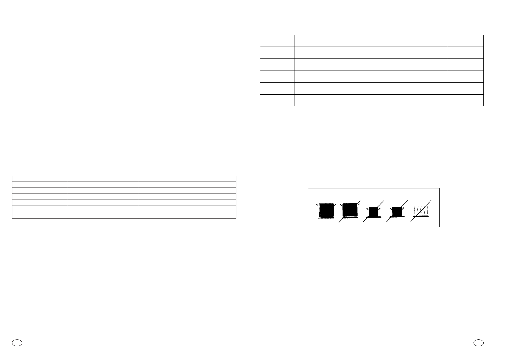
SÍ NO NO NO NO
La spia segnala il funzionamento delle piastre, per cui sarà accesa in tutte le posizioni
fuorchè la posizione di spento. Nei piani cottura ove è prevista la piastra vetro ceramica
una spia rossa supplementare segnerà il calore residuo sino al completo raffreddamento.
L’inserimento della piastra è segnalato dall’apposita spia.
Nell’uso delle piastre elettriche si raccomanda di utilizzare solo recipienti con fondo perfettamente piatto e con il diametro più vicino a quello della piastra prescelta e comunque mai inferiore ad esso (fig. 10). Si consiglia di asciugare bene il fondo dei recipienti,
di evitare trabocchi dovuti all’ebollizione e di non lasciare mai le piastre accese senza
pentola o con pentola vuota.
alimento
Cottura a fuoco lento, besciamella, stufato, riso al latte, uova al piatto...
Legumi secchi, surgelati, frutta, acqua bollente...
Mele al vapore, verdure fresche, pasta, crepe, pesce...
Cotture più impegnative, omlette, bistecche, trippa...
IT
USO DELLE PIASTRE ELETTRICHE O IN GHISA
Per il miglior funzionamento ed il minor consumo di energia, regolare la posizione delle
manopole delle piastre elettriche attenendosi ai consigli della tabella seguente.
potenza
SPENTO
LENTO
MODERATO
MEDIO
FORTE
0
1
2
3
4
POS. pastra
vetro ceramica
(Per piani in vetroceramica o similare): “ATTENZIONE - se la superficie è incrinata,
spegnere l’apparecchio per evitare l’eventualità di scosse elettriche”
Attenzione: per le versioni dotate di piastra elettrica “ausiliaria” la scelta dei recipienti
è da effettuarsi solo dopo aver letto il paragrafo “Uso delle piastre elettriche”.
7
USO DEI BRUCIATORI
Per accendere i bruciatori del piano di cottura, avvicinare una fiamma al bruciatore,
quindi premere e girare in senso antiorario la manopola corrispondente, fino alla posizione di massimo.
Se i bruciatori non vengono usati per diversi giorni attendere qualche secondo prima
dell’accensione per dare modo all’aria esistente nelle tubazioni di uscire.
Per apparecchi dotati di accensione elettronica agire come segue:
— premere e ruotare la manopola in senso antiorario fino alla piccola stella
H
— azionare l’accensione premendo l’apposito tasto.
Per i piani cottura dotati di accensione automatica è sufficiente premere e ruotare la
manopola fino alla piccola stella
H
Il generatore produrrà una serie di scariche fintanto che è mantenuta la pressione sulla manopola.
Se la fiamma non si accende entro 5 secondi riportare la manopola in posizione 0 e
ripetere l’operazione.
Per i modelli dotati di rubinetto con sicurezza (che interrompono il flusso del gas in
caso di spegnimento accidentale della fiamma) i bruciatori vengono accesi come sopra descritto, facendo attenzione
a mantenere premuta a fondo la manopola
per circa 5-6 secondi dopo l’accensione della fiamma
.
Trascorso tale tempo, necessario al dispositivo di sicurezza per inserirsi, la fiamma risulterà permanente.
ATTENZIONE: prima di accendere i bruciatori accertarsi che essi siano ben alloggiati nelle loro sedi e non interferiscano con le candele di accensione.
Per una migliore utilizzazione dei bruciatori, si raccomanda di usare pentole a fondo
piatto di diametro adatto al bruciatore prescelto. Consultare le figure a pagina 1.
Nel caso di tegami o pentole di piccolo diametro (caffettiere, teiere, ecc.), si dovrà regolare
la potenza del bruciatore interessato accertandosi che la fiamma lambisca il fondo del tegame senza fuoriuscirne. Non è consentito l’uso di tegami con fondo concavo o convesso.
IT
Piano cottura tipo Tipo di bruciatore Ø pentola (cm)
E;H. Bruciatore anteriore dx 12÷18
E;H. Bruciatore anteriore sx 10÷18
E;H. Bruciatore posteriore dx 18÷24
E;H. Bruciatore posteriore sx 18÷24
E Bruciatore cx 24÷28
H Piastra radiante cx
non superare le dimensioni della piastra radiante
AVVERTENZA: Nel caso di una estinzione accidentale della fiamma del bruciatore, chiudere la manopola di comando e non ritentare l’accensione se non dopo almeno 1 minuto.
Prima di chiudere il coperchio, al fine di salvaguardare il cristallo temperato da eccessivi sbalzi termici, è indispensabile attendere che piastre elettriche e bruciatori si siano
raffreddati.
Se col passare del tempo i rubinetti del gas dovessero indurirsi è necessaria una nuova lubrificazione con apposito lubrificante. Tale operazione dovrà essere effettuata
esclusivamente dal Servizio Assistenza.
Page 6
Questo elettrodomestico è marcato conformemente alla Direttiva
Europea 2002/96/CE sui rifiuti da apparecchiature elettriche ed
elettroniche (WEEE).
Assicurandovi che questo prodotto sia smaltito correttamente, aiuterete ad evitare possibili conseguenze negative all’ambiente e alla salute delle persone, che potrebbero verificarsi a causa d’un errato trattamento di questo prodotto giunto a fine vita. Il simbolo sul
prodotto indica che questo apparecchio non può essere trattato
come un normale rifiuto domestico; dovrà invece essere consegnato al punto più vicino di raccolta per il riciclo delle apparecchiature elettriche ed
elettroniche.Lo smaltimento deve essere effettuato in accordo con le regole ambientali vigenti per lo smaltimento dei rifiuti.Per informazioni più dettagliate sul trattamento, recupero e riciclo di questo prodotto, per favore contattare l’ufficio pubblico di competenza (del dipartimento ecologia e ambiente), o il vostro servizio di raccolta rifiuti a domicilio, o il negozio dove avete acquistato il prodotto.
Le griglie e i piattelli cromati:
Le griglie e i piattelli cromati tendono a scurirsi con l’uso.
Questo è un fenomeno del tutto normale ed inevitabile, ma non compromette assolutamente la funzionalità del piano.
Sono tuttavia disponibili su richiesta, presso il Vostro rivenditore od i nostri Centri di
Assistenza Tecnica, i ricambi.
COPERCHIO
Il coperchio è disponibile a richiesta come dispositivo opzionabile!
Non è possibile chiudere il coperchio con la bistecchiera posizionata sulla griglia.
ATTENZIONE - Prima di chiudere il coperchio, al fine di salvaguardare il cristallo temperato da eccessivi sbalzi termici, è indispensabile attendere che piastre elettriche e
bruciatori si siano raffreddati.
ATTENZIONE - eventuali tracce di liquidi tracimati dal coperchio devono essere rimosse prima di aprirlo per evitare che i liquidi possano raggiungere parti sotto tensione elettrica.
La Casa Costruttrice non risponde delle possibili inesattezze imputabili a errori di stampa o di trascrizione, contenute
nel presente opuscolo. Si riserva di apportare ai propri prodotti quelle modifiche che ritenesse necessarie
o utili, anche nell’interesse dell’utenza, senza pregiudicare le caratteristiche di funzionalità e sicurezza.
10
IT
9
SERVIZIO ASSISTENZA CLIENTI
CERTIFICATO DI GARANZIA: cosa fare?
Il Suo prodotto è garantito, alle condizioni e nei termini riportati sul certificato inserito nel
prodotto ed in base alle previsioni del decreto legislativo 24/02, nonché del decreto legislativo 6 settembre 2005, n. 206, per un periodo di 24 mesi decorrenti dalla data di consegna del bene.
Così come riportato nei testi dei Decreti Legislativi citati, il certificato di garanzia dovrà
essere da Lei conservato, debitamente compilato, per essere mostrato al Servizio
Assistenza Tecnica Autorizzato, in caso di necessità, unitamente ad un documento fiscalmente valido rilasciato dal rivenditore al momento dell’acquisto (bolla di consegna,
fattura, scontrino fiscale, altro) sul quale siano indicati il nominativo del rivenditore, la data di consegna, gli estremi identificativi del prodotto ed il prezzo di cessione.
Resta pure inteso che, salvo prova contraria, poiché si presume che i difetti di conformità che si manifestano entro sei mesi dalla consegna del bene esistessero già a tale
data, a meno che tale ipotesi sia incompatibile con la natura del bene o con la natura del
difetto di conformità, il Servizio di Assistenza Tecnica Autorizzato Gias, verificato il diritto
all’intervento, lo effettuerà senza addebitare il diritto fisso di intervento a domicilio, la
IT
Evitare di lasciare sulle parti smaltate, verniciate o in acciaio inox sostanze acide o
alcaline (succo di limone, aceto, ecc.).
I bruciatori vanno puliti con acqua saponata; se si vuole conferire loro l’originale brillantezza, basta pulirli con i prodotti specifici per le leghe di alluminio.
Dopo ogni pulitura asciugare perfettamente i bruciatori e ricollocarli nelle loro sedi.
È indispensabile controllare che il rimontaggio avvenga in modo perfetto, in
quanto un non corretto posizionamento dei componenti può essere causa di
gravi anomalie nella combustione.
(Tutti i piani): “ATTENZIONE - per la pulizia del piano non deve essere utilizzato un
pulitore a vapore”
manodopera ed i ricambi. Per contro, nel successivo periodo di diciotto mesi di vigenza
della garanzia, sarà invece onere del consumatore che intenda fruire dei rimedi accordati dalla garanzia stessa provare l’esistenza del difetto di conformità del bene sin dal
momento della consegna; nel caso in cui il consumatore non fosse in grado di fornire
detta prova, non potranno essere applicate le condizioni di garanzia previste e pertanto
il Servizio di Assistenza Tecnica Autorizzato Gias effettuerà l’intervento addebitando al
consumatore tutti i costi relativi.
ESTENSIONE DELLA GARANZIA FINO A 5 ANNI : come?
Le ricordiamo inoltre che sullo stesso certificato di garanzia convenzionale Lei troverà le
informazioni ed i documenti necessari per prolungare la garanzia dell’apparecchio sino
a 5 anni e così, in caso di guasto, non pagare il diritto fisso di intervento a domicilio, la
manodopera ed i ricambi.
Per qualsiasi informazione necessitasse, La preghiamo rivolgersi al numero telefonico
del Servizio Clienti 0392086811.
ANOMALIE E MALFUNZIONAMENTI: a chi rivolgersi ?
Per qualsiasi necessità il centro assistenza autorizzato è a Sua completa disposizione
per fornirLe i chiarimenti necessari.
UN SOLO NUMERO TELEFONICO PER OTTENERE ASSISTENZA.
Qualora il problema dovesse persistere, componendo il
“Numero Utile” sotto indicato, sarà messo in contatto direttamente con il Servizio Assistenza Tecnica Autorizzato che
opera nella Sua zona di residenza.
Attenzione, la chiamata è a pagamento; il costo verrà comunicato, tramite messaggio vocale, dal Servizio clienti dell’o-
peratore telefonico utilizzato. Dettagli sono presenti sul sito internet www.hoover.it.
MATRICOLA DEL PRODOTTO. Dove si trova?
È indispensabile che comunichi al Servizio Assistenza Tecnica Autorizzato la sigla del
prodotto ed il numero di matricola (16 caratteri che iniziano con la cifra 3) che troverà
sul certificato di garanzia oppure sulla targa matricola del prodotto (applicata sotto al
prodotto). In questo modo Lei potrà contribuire ad evitare trasferte inutili del tecnico, risparmiando oltretutto i relativi costi.
Page 7
12
INSTRUCTIONS FOR THE INSTALLER
INSTALLATION
The Purchaser is responsible for the installation of the hob. The Manufacturer does not
accept any responsibility for any damage or loss resulting from incorrect installation,
and as such this will not covered by the Manufacturer’s Guarantee.
The hob may be installed in any worktop which is heat resistant to a temperature of
100° C, and has a thickness of 25 - 45 mm. The dimensions of the insert to be cut out
of the worktop are in shown in Fig. 1.
If the Hob is fitted next to a cabinet on either side, the distance between the Hob and the
cabinet must be at least 15 cm (see Fig. 2); while the distance between the hob and the
rear wall must be at least 5,5 cm.
The distance between the hob and any
other unit or appliance above it (e.g. An extractor hood) must be no less than 70 cm
(fig.2).
When there is an accessible space between
the built-in hob and the cavity below, a dividing wall made of insulating material should
be inserted (wood or a similar material)
(fig.
3).
Important - The diagram below shows
how the sealant should be applied.
The Hob unit is fitted by attaching the Fixing
Clamps supplied, using the holes at the base of the unit.
Fig. 1
Fig. 2
Fig. 3
accessible space
GB IE
Plan 60 Plan 75
5 a gas
- / si
si
PL 73/PL 74
1
1
1
11,25 kW
818 g/h
220-240/50
BUILT IN HOBS
Burners/hotplates
Type / reference
Flame failure device
Little burner AUS ø 50 mm
Double ring burner QC ø 135 mm
Ultra rapid burner UR ø 110 mm
Semirapid burner SR ø 75 mm
Rapid burner R ø 100 mm
Griddle 174x160 mm
Griddle 229x379
Electric plate ø80 PE
Electric plate ø145 PE
Electric plate 160x265 mm PE
Installed gas Type/Power:
G20 20mbar* (METHANE)
G30 28-30mbar (GPL)
Installation class
Voltage/Frequency V/Hz
Electrical imput power
Electronic ignition
Product dimension WXD (mm)
4 a gas
1 electr.
- / si
si
PL 73/PL 74
1
1
7,75 kW
636 g/h
220-240/50
11
* Manufacturer setting IE cat. II2H3 + GB cat. II2H3 +
Tab. 1
This appliance has been designed for non-professional, i.e. domestic, use.
GB IE
Page 8

14
ELECTRICAL CONNECTION (FOR U.K. ONLY)
Warning - this appliance must be earthed
This appliance is designed for domestic use only. Connection to the mains supply must
be made by a competant electrician, ensuring that all current regulations concerning
such installations are observed.
The appliance must only be connected to a suitably rated spur point, a 3 pin 13 amp
plug/socket is not suitable. A double pole switch must be provided and the circuit must
have appropriate fuse protection. Further details of the power requirement of the individual product will be found in the users’ instruction and on the appliance rating plate.
In
the case of built-in product you are advised, should you wish to use a longer cable than
the one supplied, that a suitably rated heat resistant type must be used.
The wiring must be connected to the mains supply as follows:
CONNECT TO SPUR TERMINAL
Green & Yellow Wire Earth Connection
Blue Wire Neutral Connection
Brown Wire Live Connection
Note: We do not advocate the use of earth leakage devices with electric cooking appliances installed to spur points because of the «nuisance tripping» which may occur. You are
again reminded that the appliance must be correctly earthed, the manufacturer declines any responsibility for any event occurring as a result of incorrect electrical installation.
Declaration of compliance: This equipment, in the parts intended to come into contact with food, complies with the regulations laid down in EEC directives 89/109.
This appliance complies with directive 89/336/EEC, 73/23/EEC, 90/396/EEC and
the following changes.
GAS CONNECTION (FOR U.K. ONLY)
The labels on the Hob indicate the types of gas that can be used.
It is possible to use other types of gas after carrying out simple modifications.
Warning: If gas can be smelt in the vicinity of this appliance turn off the gas supply to the
appliance and call the engineer directly. Do not search for a leak with a naked flame.
GB IE
13
FOR U.K. ONLY
INSTRUCTIONS FOR THE INSTALLER
The following information is intended for qualified and competant persons only who will
ensure that your appliance is installed correctly. All current legislation concerning the installation of Gas appliances must be observed by the installer*
* For the U.K. only - By law, the gas installation/commissioning must be carried out by a
«Corgi», registered installer.
This appliance must be installed in accordance with applicable regulations and should only be
used in well-ventilated locations. Before using this appliance carefully study the instruction book.
Suitable location
A gas-powered cooking appliance produces heat and humidity in the area in which it is
installed. For this reason you should ensure good ventilation either by keeping all natural air passages open or by installing an extractor hood with an exhaust flue. Intensive
and prolonged use of the appliance may require extra ventilation, such the opening of a
window or an increase in speed of the electric fan, if you have one.
If a hood cannot be installed, an electric fan should be fitted to an outside wall or window as long there are air vents in the area.
The electric fan should be able to carry out a complete change of air in the kitchen 3-5
times every hour. The installer should follow the relavant national standards.
If a hob of 60 cm is fitted above an oven which is not equipped with fan cooling system
it is recommended that openings are created within the built in furniture to ensure correct air circulation.
The size of these openings must be at least 300 cm
2
and placed as shown in fig. 4.
When a 75 cm hob is fitted over a built in oven, the latter must be fan cooled.
FIG. 4
60 Cm
2
240 Cm
2
120 Cm
2
180 Cm
2
GBIE
Page 9

16
ADAPTING THE HOB TO DIFFERENT TYPES OF GAS
To adapt the Hob for use with different types of gas, carry out the following instructions:
— remove the grids and burners
— insert on hexagonal spanner (7 mm) into the burner support (Fig. 6)
— unscrew the injector and replace it with one suitable for the gas to be used (see
Table of gas consumption)
1/2 GAS
CONICAL
A) As illustrated, assemble parts in sequence:
A) fixed pipe
B) washer
C) Elbow fitting with
tapered thred
connection
2) Tighten the joints
with the Spanners,
remembering to twist
the pipes into position.
3) Attach fitting C to
mains gas supply using rigid copper pipe
or flexible steel pipe.
IEGB
For some models a conic link is furnished to outfit for the installation in the countries where this type of link is obligatory; in the following figures it is pointed out how to recognize
the different types of links. In every case the cylindrical part of the link has to be connected to the hob.
To prevent any potential damage to the hob please carry out the installation following
this sequence:
GB IE
Fig. 6
INJECTOR
CYLINDRICAL
CONICAL
Fig. 5
15
LIVE L
EARTH
NEUTRAL N
MAINS
SUPPLY
BROWN WIRE
GREEN/YELLOW WIRE
BLUE WIRE
POWER
CABLE
These instructions are for Fitters qualified for installation of equipment in line with the
relevant national standard. All work must be carried out with the electricity supply disconnected.
The rating plate on the hob shows the type of gas with which it is designed to be used.
It is possible to use other types of gas after carrying out some simple modifications.
(See the instructions in the following paragraphs).
connection to the mains gas supply or gas cylinder should be carried out according to
the relevant national standards, after having checked that it is regulated for the type of
gas with which it will be supplied. If it is not correctly regulated follow the instructions in
the paragraph entitlet «Adaption for different types of gas». For liquid gas (cylinder
gas) use pressure regulators which comply with the relevant national standards.
N.B.: for safe operation, economic use of energy and to ensure greater durability
of the
appliance, make sure that the supply pressure conforms with the values shown
in the
table on page 44.
Use only pipes, washers and sealing washers which comply with the relevant national
standards.
When connecting the hob to the gas supply via use of flexible hoses please ensure
that the maximum distance covered by the hose does not exceed 2 metres.
N.B.: carry out a final check for leaks on the pipework using a soapy solution.
Never use a flame. Also, make sure that the flexible pipe cannot come into contact with a moving part of
the cabinet (eg, a drawer) and that it is not situa
ted
where it could be damaged.
GAS CONNECTION
ELECTRICAL CONNECTION
Check the data on the rating plate, located on the outside of the unit, to ensure that the
supply and input voltage are suitable.
Before connection, check the earthing system.
By Law, this appliance must be earthed. If this regulation is not complied with, the
Manufacturer will not be responsible for any damage caused to persons or property.
If a plug is not already attached, fit a plug appropriate to the load indicated on the rating
plate. The earth wire is coloured yellow/green. The plug should always be accessible.
Where the Hob is connected direct to the electricity supply, a circuit breaker must be
fitted with at least a 3 mm contact spacing when in the open position.
If the power supply cord is damaged this is to be replaced by a qualified engineer so as
to prevent any potential risk.
The earth wire ( green a yellow coloured) must be at least 10 mm longer than the live
and neutral wires.
The section of the cable used must be of the correct size in relation to the absorbed
power of the hob.
Please check rating plate for the power details and ensure that the power supply cord
is of the type H05RR-F, H05VV-F, H05V2V2-F.
GBIE
Page 10

If over the years the gas taps become stiff to turn it is necessary to lubricate them.
Such operation must be carried out only by qualified Service Engineers.
Warning use the electric ring/hotplate only after reading the paragraph related to choi-
ce of pans specifically with reference to “Use of electric hotplates”.
18
USING THE GAS BURNER
To ignite the burners, place a lighted taper close to the burner, press in and turn the
control knob anti-clockwise.
If the burners have not been used for a couple of days, wait for a few seconds before
lighting the burner, this will allow any air present in the pipes to escape.
For appliances fitted with electronic ignition carry out the following:
• push in and turn the knob anticlockwise to the
H
symbol.
• ignite the burner by pressing the sparker button.
For hobs fitted with automatic ignition simply push in and turn the knob to the
H
symbol.
The ignition system will continue to generate sparks as long as the gas tap is being
pressed.
If the burner is not ignited within 5 seconds, turn the knob to the 0 position and repeat
the operation.
For models fitted with a safety tap (which cuts-off the flow of gas if the flame is accidentally extinguished) the burners are ignited ad described above, but care must be
taken to keep the knob pressed in for 5 or 6 seconds after the flame is ignited.
ATTENTION:
Prior to switching on the gas hob ensure that the burners and bur-
ner caps are correctly placed within their position.
GENERAL ADVICE
For the best results, the flat-bottomed pans size should match the gas burner size as
follows. See fig. pag. 11.
For smaller containers the gas burner should be regulated so that the flame does not
overlap the base of the pan. Vessels with concave or convex base should not be used.
WARNING: If a burner is accidentally extinguehed, turn the knob to the off position and do not attempt to re-ignite if for at least 1 minute.
To protect the glass lid from damage and in the interests of safety, the burners/plates
must be turned off and the burner/pan support/plate area must be cool before closing
the lid down.
GB IE
Hob type Burner type Ø pan / pot (cm)
E;H. R/H front burner 12÷18
E;H. L/H front burner 10÷18
E;H. R/H rear burner 18÷24
E;H. L/H rear burner 18÷24
E. Central burner 24÷28
H. Central radial plate CX do not overhang the radiant plate
REGULATING THE MINIMUM FLAME
After lighting the burners, turn the control knob to the minimum setting and then remove the knob (this can easily be removed by apply a gentle pressure).
Using a small «Terminal» type screwdriver the regulating screw can be adjusted as in
Fig. 7. Turning the screw clockwise reduces the gas flow, whilst turning it anticlockwise
increases the flow – Use this adjustment to obtain a flame of approximately 3 to 4 mm
in length and then replace the control knob.
When the gas supply available is LPG (Bottle gas)- the screw to set the idle flame must
be turned (clockwise) to the end stop.
Screws regulating
(for differend models)
17
Fig.7
Working
burner
little
large
medium
maxi
double ring
G20
G25
ø gas jet
1/100 mm
G30
G31
ø gas jet
1/100 mm
GZ 350
ø gas jet
1/100 mm
G20 20mbar G30 28-30mbar
G31 37mbar GZ350 13mbar
Qn
kW
QminWl/h
G20
l/h
GZ350
g/h
G30
g/h
G31
G20 25mbar
G30 36mbar
G25 25mbar
G31 30mbar
Qn
kW
QminWl/h
G20
g/h
G30
Qn
kW
QminWl/h
G25
g/h
G31
76
101
118
144
141
50
66
80
94
96
104
132
160
190
191
1
1,75
2,5
3,5
3,5
230
360
530
700
1750
95
167
238
333
333
132
232
331
463
463
73
127
182
254
254
71
125
179
250
250
1,2
2
2,8
4
4
260
410
620
830
1900
114
190
267
381
381
87
145
204
291
291
0,9
1,6
2,25
3,2
3,2
230
360
530
700
1750
100
177
255
354
354
64
114
161
229
229
Table of gas consumption 1 W 0,860 Kcal/h
When you have carried out the new gas regulation, replace the old gas rating plate on your appliance with one (supplied with hob) suitable for the type of gas for
which it has been regulated.
USE OF HOB
USER INSTRUCTIONS
This appliance must only be used for the purpose for which it is intended, domestic
cooking, and any other use will be considered improper and could therefore be dangerous. The Manufacturer will not be responsible for any damage or loss resulting from
improper use.
Page 11

AFTERCARE
Before calling out a Service Engineer please check the following:
— that the plug is correctly inserted and fused;
— that the gas supply is not faulty.
If the fault cannot be identified:
switch off the appliance — do not tamper with it — call the Aftercare Service Centre.
COVER
The cover is available as optional accessory.
It is not possible to close the lid with the steak griddle placed over a burner.
WARNING - should any spillage occur on the lid ensure the liquid spilt is wiped off the
lid before opening the lid and cause the liquid to reach any electric part.
WARNING - Before closing the cover, to protect it from excessive temperature changes, always wait until burners or plates have completely cooled down.
Chromed grids and burners
Chromed grids and burners have the tendency to dark with the use.
This is a normal and inevitable phenomenon, but it doesn’t jeopardize absolutely the
functionality of the hob.
In anycase from our after sales service centre the spare parts are available.
The Manufacturer will not be responsible for any inaccuracy resulting from printing or transcript errors contained in this brochure. We reserve the right to carry out modifications to products as required, including
the interests of consumption, without prejiudice to the characteristics relating to safety or function.
Never use abrasives, corrosive detergents, bleaching agents or acids. Avoid any acid
or alkaline substances (lemon, juice, vinegar etc.) on the enamelled, varnisched or stainless steel sections.
The burners can be cleaned with soapy water. To restore their original shine, use a
household stainless steel cleaner. After cleaning, dry the burners and replace.
It is important the Burners are replaced correctly.
(For all hobs): “WARNING - do not use steam cleaners to clean the hobs”.
20
MAINTENANCE AND CLEANING
Before cleaning the Hob, ensure the appliance has cooled down. Remove the plug from
the socket or (if connected directly) switch off the electricity supply.
When cleaning the enamelled, varnished or chrome sections, use warm soapy water
or a non caustic detergent. For stainless steel use an appropriate cleaning solution.
Hotplates should only be cleaned with a cotton cloth coated with vaseline or seed oil.
GB IE
19
GBIE
Fig. 10
YES NO NO NO NO
The light indicates the hotplate is on irrespective of the power setting.
In the vetroceramic hobs a residual heat indicator light comes on and remains lit till the
hob plate is cooled down.
Only pans which have smooth flat bases should be used on the electric hotplates. The
size of the pan should be as close as possible to the diameter of the hotplate, and never smaller (see Fig. 10). The base of the pan should be dry and spillages should be
avoided. Empty pans should not be left on the plates, nor should the plates left switched
on without a pan.
food stuff
Simmering, sauces, stews, milk puddings, poached eggs
Vegetables, frozen foods, boiling water
Fresh Vegetables, pasta, fish, pancakes.
Omelettes, steaks
power setting
OFF
LOW
MODERATE
MEDIUM
HIGH
USE OF ELECTRIC HOTPLATES OR CERAMIC ELEMENTS.
For the best use of the electric hotplates and to minimise energy consumption, the following recommendations should be noted.
0
1
2
3
4
No. setting ceramic element
(Ceramic hobs or similar): “WARNING - should any crack appear on the surface turn
the appliance off to prevent potential electric shock.
Page 12

21
GBIE
This appliance is marked according to the European directive
2002/96/EC on Waste Electrical and Electronic Equipment
(WEEE).
By ensuring this product is disposed of correctly, you will help prevent potential negative consequences for the environment and human health, which could otherwise be caused by inappropriate
waste handling of this product.
The symbol on the product indicates that this product may not be
treated as household waste. Instead it shall be handed over to the
applicable collection point for the recycling of electrical and elec-
tronic equipment.
Disposal must be carried out in accordance with local environmental regulations
for waste disposal.
For more detailed information about treatment, recovery and recycling of this product, please contact your local city office, your household waste disposal service or
the shop where you purchased the product.
Page 13

23
ISTRUÇÕES DE INSTALAÇÃO
INSTALAÇÃO
A instalação é efectuada pelo comprador. O fabricante não é responsável por este trabalho. Qualquer intervenção solicitada ao fabricante devido a uma instalação incorrecta não está ao abrigo da garantia.
As placas encastráveis estão previstas para serem instaladas em qualquer material,
que seja resistente a temperaturas de 100 °C e cuja espessura varie entre os 25 e
45 mm. As dimensões do forno para ser encastrado devem respeitar as dimensões
indicadas na fig. 1. No caso de as placas
serem encastradas sobre o lado esquerdo ou
direito do móvel, a distância da parede vertical e a borda da placa deve ser pelo menos de 15 cm (fig. 2); a distância entre a parede posterior e a borda da placa deve ser
no minimo 5,5 cm.
A placa deve sempre ficar a uma distância
de, pelo menos, 70 cm de qualquer unidade
ou aparelho instalado sobre ela (como, por
exemplo, um extractor) (fig.2).
Quando existe um espaço acessível entre a
boca incorporada e a cavidade inferior, deve
ser inserida uma parede divisória feita de
material isolante (madeira ou um material similar)
(fig. 3).
Importante - a figura que se segue indica como aplicar o produto vedante.
A fixação ao móvel é feita através de braçadeiras de fixação fornecidas como acessórios. Na parte inferior da placa encontram-se
os orificios nos quais devem ser enroscadas as braçadeiras de fixação.
PT
Fig. 1
Fig. 2
Fig. 3
espaço acessível
Plan 60 Plan 75
22
* Parâmetros de fabrico PTcat. II2H3 +
Tab. 1
Este aparelho foi concebido para uma utilização não profissional.
PT
5 a gas 4 a gas
1 electr.
- / si - / si
si si
PL 73/PL 74
PL 73/PL 74
11
1
1
1
11,25 kW
7,75 kW
818 g/h 636 g/h
220-240/50 220-240/50
PLACAS ENCASTRÁVEIS
Queimadores/Zonas de calor
Modelos
Dispositivo de segurança em caso de apagamento de chama
Queimador pequeno AUS ø 50 mm
Queimador duplo DQ ø 135 mm
Queimador ultra rápido UR ø 110 mm
Queimador semi rápido SR ø 75 mm
Queimador rápido R ø 100 mm
Zona para grelhar 174x160
Zona para grelhar 229x379
Chapa eléctrica ø80 PE
Chapa eléctrica ø145 PE
Chapa eléctrica 160x265 PE
Tipo e potência de gás:
G20 mbar* (METHANE)
G30 28-30mbar (GLP)
Classe de instalação
Voltagem/Frequência V/Hz
Potência eléctrica
Ignição electrónica
Dimensões do produto L x P (mm)
Page 14

25
Sempre que o cabo de alimentação de energia estiver danificado deverá o mesmo ser
substituído por um técnico devidamente qualificado, de modo a evitar qualquer risco
potencial.
O fio de ligação à terra (verde e amarelo) deve ser pelo menos 10 mm mais comprido
do que os fios sob tensão e neutro.
O cabo de alimentação de energia deve ter uma secção transversal adequada à potência máxima absorvida pela placa.
O fabricante recomenda que consulte a placa de características do aparelho para se
informar sobre as características eléctricas do mesmo e ainda que se assegure de que
o cabo de alimentação de energia seja do tipo H05RR-F, H05VV-F, H05V2V2-F.
Declaração de conformidade. Este aparelho destina-se ao contacto com produtos
alimentares e está em conformidade com a norma CEE 89/109.
Aparelho em conformidade com as directivas europeias 89/336/CEE, 90/396/CEE,
73/23/CEE e modificações sucessivas.
Estas instruções são dirigidas ao pessoal autorizado para a instalação deste electrodoméstico em conformidade com as normas vigentes. Qualquer intervenção deverá
ser efectuada com o aparelho desligado da corrente eléctrica.
Na bancada de trabalho está indicado o tipo de gás para o qual o aparelho está preparado. No entanto pode utilizar-se outros tipos de gás; torna-se necessário proceder apenas a algumas simples adaptações
(ver instruções nos parágrafos seguintes).
A ligação do aparelho ao tubo ou à botija de gás deve ser efectuada conforme indicado pelas normas, no entanto, previamente deve-se certificar se o aparelho está regulado para o tipo de gás escolhido para a alimentação. Caso contrário deve-se proceder ás operações indicadas no capítulo «Adaptação a diversos tipos de gás».
Se o
aparelho for alimentado com gás liquido de botija, deve-se utilizar reguladores
de pressão de acordo com as normas vigentes.
Importante: para um funcionamento com o máximo de segurança, para uma utilização adequada da energia e uma maior duração de aparelho, verifique se a pres
são
de alimentação está de acordo com os valores indicados na tabela da pág. 56).
Utilizar exclusivamente tubos e guarnições de fixação em conformidade com as normas vigentes.
Sempre que a placa for ligada à fonte de abastecimento de gás por meio de mangueiras flexíveis, o seu comprimento não poderá ser superior a 2 metros.
Importante: uma vez concluida a instalação é fundamental verificar se as uniões
e os tubos, e demais componentes de ligação, se encontram devidamente ligados, a melhor forma de proceder a esta verifificação é recorrer a uma solução de
água com sabão. A existência de eventuais fugas nunca deverá ser verificada
com uma chama. Certifique-se de que o tubo flexível não esteja em contacto com
uma parte móvel do módulo de encastre (gaveta) e que não seja colocado em locais onde possa ser danificado.
LIGAÇÃO À ALIMENTAÇÃO DE GÁS
PT
FASE L
TERRA
NEUTRO N
FONTE DE
ALIMENTAÇÃO
ELECTRICA
FIO CASTANHO
FIO VERDE/AMARELO
FIO AZUL
CABO DE
ALIMENTAÇÃO
24
LOCAL DE INSTALAÇÃO
A utilização de um aparelho de cozedura a gás produz calor e humidade no local onde
está instalado.
Por conseguinte deve proporcionar-se uma boa ven
tilação do local, mantendo abertos
os orificios de ventilação ou instalando um exaustor com canal de descarga (fig. 2).
Uma utilização intensa e prolongada do aparelho poderá necessitar de uma ventilação
adicional, por exempio a abertura de uma janela ou de uma ventilação mais eficaz aumentando a potência de aspiração mecânica se esta for
existente. No caso de o apa-
relho nâo estiver provido
de um dispositivo de segurança, a ventilação (fig. 2) deve de
ser no mínimo de 200 cm.
2
.
No caso de não ser possível instalar um exaustor torna-se necessário utilizar um ventilador eléctrico aplicado na parede exterior ou à janela sempre que existem no local
aberturas para a entrada de ar.
Este ventilador eléctrico deve ter capacidade suficiente que assegure a renovação de
ar de 3 a 5 vezes o seu volume de ar por hora. O instalador deve observar as normas
vigentes.
Sempre que a placa de 60 cm seja instalada sobre um forno que não esteja equipado
com um sistema de refrigeração por ventoinha, o fabricante recomenda que sejam introduzidas aberturas no móvel em que as unidades estão encastradas, a fim de assegurar uma circulação correcta do ar. Estas aberturas devem ter uma área mínima de
300 cm2e devem estar localizadas nos pontos indicados na figura 4.
As placas de 75 cm devem ser combinadas com fornos equipados com o sistema integral de refrigeração por ventoinha.
LIGAÇÃO ELÉCTRICA
Controlar os dados indicados na placa de características colocada no aparelho, que
se encontra na parte inferior do lado exterior do mesmo. Verifique também a tensão
nominal de rede e a potência que devem ser adequadas para o seu funcionamento.
Antes de proceder à ligação deve verificar a eficácia da instalação da tomada de ligação à terra. Atomada de ligação à terra é obrigatória. O fabricante declina toda e qualquer
responsabilidade por quaisquer prejuizos materiais ou pessoais derivados da falta
de ligação à terra ou por falta de observação das normas em vigor.
No caso dos modelos sem ficha adapte ao cabo eléctrico do aparelho uma ficha standard capaz de suportar a carga indicada na placa de características. O fio de terra do
cabo distingue-se por sua cor amarela e verde. A ficha deve ficar sempre acessível.
Pode efectuar-se a ligação à rede intercalando entre o aparelho e a rede um dispositivo omnipolar de interrupção com uma distância minima entre contactos de 3 mm.
PT
FIG. 4
60 Cm
2
240 Cm
2
120 Cm
2
180 Cm
2
Page 15

Uma vez concluida a regulaçao do gás, substituir na placa do seu aparelho a
placa de características por uma nova correspondendo ao gás instalado.
UTILIZAÇÃO DA PLACA
INSTRUÇÕES
Este aparelho só se destina ao uso para que foi especificamente concebido, ou seja
para cozinhados domésticos. Qualquer outro tipo de utilização é considerado impróprio e, portanto, perigoso.
O fabricante não se responsabiliza por eventuais danos decorrentes de uma utilização
incorrecta.
REGULAÇÃO DA ALTURA MÍNIMA DA CHAMA
Acenda os queimadores, colocando a torneira na posição correspondente ao mínimo,
e retire o botão de comando para fora (este botão de comando pode ser facilmente
extraido porquanto está montado por pressão). Isto feito, e servindo-se de uma chave
de fendas pequena, rode o parafuso de regulação da torneira (fig. 7) no sentido contrário ao dos ponteiros do relógio para aumentar a saida de gás e no sentido dos ponteiros do relógio para a diminuir, de modo a obter uma chama com uma altura de 3 a 4 mm.
Sempre que o gás disponível for o gás GPL (gás de garrafa), o parafuso de regulação
da chama piloto tem de ser rodado (no sentido dos ponteiros do relógio) até prender.
Parafuso de regulação mínima da torneira
(em função dos diversos modelos)
27
Fig. 7
PT
Tabela de consumos de gás 1W = 0,860 kcal/h
Queimador
em função
Pequeno
Rápido
Semi-rápido
Ultra-rápido
Duplo
G20
G25
ø jniectores
1/100 mm
G30
G31
ø jniectores
1/100 mm
GZ 350
ø jniectores
1/100 mm
G20 20mbar G30 28-30mbar
G31 37mbar GZ350 13mbar
Qn
kW
QminWl/h
G20
l/h
GZ350
g/h
G30
g/h
G31
G20 25mbar
G30 36mbar
G25 25mbar
G31 30mbar
Qn
kW
QminWl/h
G20
g/h
G30
Qn
kW
QminWl/h
G25
g/h
G31
76
101
118
144
141
50
66
80
94
96
104
132
160
190
191
1
1,75
2,5
3,5
3,5
230
360
530
700
1750
95
167
238
333
333
132
232
331
463
463
73
127
182
254
254
71
125
179
250
250
1,2
2
2,8
4
4
260
410
620
830
1900
114
190
267
381
381
87
145
204
291
291
0,9
1,6
2,25
3,2
3,2
230
360
530
700
1750
100
177
255
354
354
64
114
161
229
229
26
ADAPTAÇÃO A DIVERSOS TIPOS DE GÁS
Para adaptar a placa a um tipo de gás diferente aquele para o qual está preparada,
deve-se proceder as seguintes operações:
— remover a grelha e o queimador
—
introduzir uma chave hexagonal para tubos (7 mm) no suporte do queimador (fig.
6).
— desaparafusar o injector e substitui-lo pelo que melhor se adeque ao tipo de gás
disponível ver tabela de consumo de gás.
1/2 GAS
CILINDRICO
1) Enroscar as partes
na sequência ilustrada
A) Tubagem
B) Anilha
C) Junta
2) Apertar com força
as juntas, utilizando
as chaves hexagonais,
tendo atenção para
orientar a junta na direcção desejada antes
de começar a apertar.
3) Ligar a iunta C à rede de alimentação de
gás através de um tubo rígido de cobre ou
um tubo flexível de
aco inoxidável.
PT
Alguns modelos de placas de cozedura são fornecidos com uma ligação cónica, para
permitir a instalação desses modelos de placa de cozedura nos países em que este
tipo de ligação é obrigatória; as figuras que se seguem mostram como reconhecer os
diferentes tipos de ligações. O componente cilíndrico da ligação tem sempre de ser
ligado à placa de cozedura.
A fim de evitar potenciais danos na placa, a instalação da mesma deverá ser feita de
acordo com a seguinte sequência:
PT
Fig. 6
INJECTOR
Fig. 5
Page 16

29
MANUTENÇÃO E LIMPEZA
Antes de efectuar qualquer operação, desligue sempre a ficha da tomada de corrente ou desligue o aparelho da corrente por meio do interruptor geral da instalação
eléctrica.
Espere sempre que a placa arrefeça antes de proceder a qualquer limpeza.
Limpe as peças esmaltadas, envernizadas ou cromadas com água morna e sabão ou
detergente líquido não abrasivo.
Para as peças de aço inoxidável, utilize um algodão ou um pano embebido em óleo
de vaselina ou de sementes. Limpe e passe com álcool.
Nunca utilize produtos abrasivos, detergentes corrosivos, branqueadores e ácidos na
limpeza.
PT
Fig. 10
SIM NO NO NO NO
A luz indicadora do funcionamento dos discos é independente do indicador da potência. Nas placas vitrocerâmicas a luz indicadora do calor residual liga-se até atingir a
temperatura pretendida e desliga-se quando o calor vai diminuindo.
O funcionamento da chapa é assinalado pelos indicadores especificos.
Sempre que utilizar as placas eléctricas, utilize somente recipientes de fundo perfeitamente plano e com o diâmetro similar ao da placa escolhida, mas nunca inferior a este
(fig. 10). Seque bem o fundo dos recipientes, evite derramar os líquidos em ebulição
e não deixe nunca as placas acesas sem um recipiente, cheio ou vazio, em cima.
Para cozinhar um prato a lume brando, para fazer molho béchamel, para
guisados, arroz doce, ovos estrelados, etc.
Legumes secos, alimentos congelados, fruta, ferver água, etc.
Para cozer maçãs a vapor, legumes frescos, massas, crepes, peixes, etc.
Para cozinhar pratos a lume mais forte, para fritar omeletes, para cozinhar
bifes, tripas, etc.
DESLIGADO
BAIXO
MODERADO
MÉDIO
ALTO
indicator
de Potência
ingredientes
UTILIZAÇÃO DAS CHAPAS ELÉCTRICAS OU CERAMICÂS
Para uma melhor utilização das chapas eléctricas e um menor consumo de energia
é recomendável regular a posição dos botões de comando das chapas de acordo com
os dados da tabela que se segue:
0
1
2
3
4
Níveis de calor
das placas cerâmicas
(Placas cerâmicas ou similares): ATENÇÃO - caso encontre alguma racha na placa,
deverá desligá-la de imediato para prevenir um eventual choque eléctrico.
Atenção Só deverá utilizar a placa depois de ter lido o capítulo relativo à escolha dos
recipientes correctos para serem utilizados com a sua placa, ou seja, o capítulo intitulado “Utilização de placas eléctricas”.
28
UTILIZAÇÃO DOS QUEIMADORES
Para acender os queimadores da placa basta aproximar uma chama do queimador, e,
isto feito, premir e rodar o respectivo botão para a esquerda, até à posição correspondente ao máximo. Se os queimadores não forem utilizados durante vários dias,
será conveniente esperar alguns segundos antes de os acender, para dar tempo ao
ar existente nos tubos para sair.
Para fogões equipados com acendedor electrónico, proceder assim:
• premir e rodar o botão do sentido contrário ao dos ponteiros do relógio para o símbolo
H
• acender o queimador premindo o botão de faisca
Para bocas equipadas com ignição automática, basta premir e rodar o botão para o símbolo
H
O sistema de ignição (isqueiro) continuará a gerar faíscas enquanto o botão de comando estiver a ser premido.
Se o queimador não acender em 5 segundos, rodar o botão para a posição 0 e repetir a
operação.
Para os modelos equipados com torneira de segurança (que corta o fluxo de gás quando
a chama se extingue acidentalmente) os queimadores são acesos como descrito anteriormente, mas deve ter-se o cuidado de manter o botão premido durante 5 ou 6 segun-
dos após o acendimento.
Este tempo permite ao dispositivo de segurança activar-se e que a chama permaneça
acesa.
Atenção: Antes de ligar a placa a gás, deverá certificar-se de que os queimado-
res e os espalhadores estão correctamente instalados.
Para garantir uma melhor utilização dos queimadores, recomendamos a utilização de tachos e panelas com diâmetros adequados ao queimador escolhido (ver fig. pag. 22):
Se os recipientes a utilizar apresentarem um diâmetro muito reduzido (cafeteiras, chaleiras, etc.) regule a chama de modo a que esta toque no fundo do recipiente sem, no
entanto, sair pelos lados. Nunca utilize recipientes com fundo côncavo o convexo.
ADVERTÊNCIA: Em caso de a chama do queimador se apagar acidentalmente,
desligar o botão e esperar no mínimo 1 minuto até voltar a acender o queimador.
Antes de fechar a tampa, a fim de proteger o vidro temperado de variações térmicas
bruscas, espere sempre que as placas eléctricas e os queimadores arrefeçam.
Se, com o passar do tempo, as torneiras do gás ficarem perras é necessário lubrificálas. Trata-se de uma operação que só deve ser levada a cabo por um técnico de-
vidamente qualificado.
PT
Tipo de placa Tipo de queimador Ø pan. / pot (cm)
E;H. Queimador frontal dx 12÷18
E;H. Queimador frontal sx 12÷18
E;H. Queimador traseiro dx 18÷24
E;H. Queimador traseiro sx 18÷24
E Queimador central 24÷28
H Queimador radiante central cx
não colocar as mãos em cima do queimador radiante
Page 17

30
Grelhas cromadas e queimadores
As grelhas cromadas e os queimadores têm tendência para escurecer com o uso.
Este è o fenómeno natural e inevitável, mas não põe de forma alguma, em perigo, o
funcionamento da placa.
TAMPA
A tampa está disponivel como acessorio opcional.
Não é possível fechar a tampa com comida na grelha da placa.
ATENÇÃO - Antes de fechar a tampa, a fim de proteger o vidro temperado de variações térmicas bruscas, espere que as placas eléctricas e os queimadores arrefeçam.
ATENÇÃO - Nunca deverá haver um derrame de líquidos na tampa da placa.
Assegure-se de que, caso aconteça algum derrame de líquidos na placa, esta deverá
ser limpa antes de a abrir para que não vá nenhum líquido para as partes eléctricas.
Salvaguardam-se erros e alterações!
PT
31
PT
ASSISTÊNCIA TÉCNICA
Se o seu electrodoméstico não estiver a funcionar nas devidas condições, e antes de
recorrer aos Serviços de Assistência Técnica autorizados, verifique se:
— a ficha está correctamente introduzida na tomada de corrente
— o fluxo de gás seja regular e os tubos de borracha não estejam dobrados em nen-
hum ponto.
Em caso de não conseguir descobrir a causa do mau funcionamento:
— desligue o electrodoméstico, não o manipule e chame os Serviços de Assistência
Técnica.
Este electrodoméstico está abrangido por uma Garantia que Ihe permite desfrutar gratuitamente dos Serviços de Assistência Técnica.
Não deixe substâncias ácidas ou corrosivas (sumo de limão, vinagre, etc.) em cima
das peças esmaltadas, envernizadas ou de aço inoxidável.
Limpe os queimadores com água e sabão: se quiser recuperar o seu brilho original,
limpe-os com produtos específicos para ligas de alumínio.
Depois de limpar os queimadores, seque-os bem e torne a colocá-los nos seus sítios
correspondentes.
Certifique-se sempre de que os queimadores ficaram correctamente montados,
já que uma montagem incorrecta pode ser causa de graves anomalias na combustão.
(PARA TODAS AS PLACAS): ATENÇÃO - Não utilize máquinas a vapor para limpar
as tampas.
Este electrodoméstico está marcado de acordo com o disposto na
directiva europeia 2002/96/CE relativa aos resíduos de equipamentos eléctricos e electrónicos (REEE).
Ao assegurar que este produto seja correctamente eliminado,
estará a prevenir eventuais consequências negativas para o ambiente e para a saúde, que, de outra forma, poderiam resultar de
um tratamento incorrecto deste produto, quando eliminado.
O símbolo patente neste produto indica que ele não pode ser tratado como lixo doméstico. Em vez disso, deve ser entregue no centro de recolha apropriado, para reciclagem do equipamento eléctri-
co e electrónico.
A eliminação deste produto deve ser levada a cabo de acordo com os regulamentos localmente aplicáveis à eliminação e ao tratamento de lixo e resíduos.
Para obter informações mais detalhadas sobre o tratamento, a recuperação e a reciclagem deste produto, agradecemos que entre em contacto com a entidade municipal competente, com o serviço de eliminação de lixos e resíduos ou com o estabelecimento comercial onde adquiriu o produto.
Page 18

33
INSTALLATIE
Aanwijzigen voor de installateur
De installatie is de verantwoording van de koper. De fabrikant is vrijgesteld van deze
verantwoordelijkheid. Als de service dients wordt ingeschakeld voor een defect ontstaan
door foutieve installatie valt dit niet onder de garantie.
Deze inbouwkookplaten zijn bestemd voor installatie in een werkblad dat bestand is
tegen temperaturen van 100 °C en een dikte hebben tussen 25 en 40 mm. Voor de
inbouwmaat dient u zich te houden aan de maten zoals aangegeven in figuur 1.
De kookplaat dient zo te worden ingebouwd dat er aan de linker- en rechterzijde minstens 150 mm. ruimte is tussen kookplaat en kasten of verticale panelen. De afstand
tussen kookplaat en
achterwand dient minstens 55 mm. te zijn (fig. 2).
De afstand tussen de kookplaat en een
afzuigkap moet minimaal 70 cm zijn.
(afb. 2).
Wanneer er een ruimte is tussen de inbouw
kookplaat en de ruimte daaronder moet er
een scheidingsplaat van isolatiemateriaal
geplaatst worden (bijvoorbeeld hout).
Tussen de scheidingsplaat en de bodem
van de lade moet een ruimte zitten van minsten 10 mm (Fig. 3).
Belangrijk- op onderstaande tekening
kunt u zien hoe de afdichtingskit moet
worden aangebracht.
Het vastzetten in het meubel geschiedt door
de bijgeleverde bevestigingsbeugels die aan de onderzijde op de daarvoor bestemde
plaats worden vastgedraaid.
of the unit.
Fig. 1
Fig. 2
Fig. 3
accessible space
NL
Plan 60 Plan 75
5 a gas
- / si
si
PL 73/PL 74
1
1
1
11,25 kW
818 g/h
220-240/50
KOOKPLATEN
Kookzones
Type verwijzing
Vlambeveiliging
Kleine brander AUS ø 50 mm
Dubbelrings brander QC ø 135 mm
Turbo brander UR ø 110 mm
Medium brander SR ø 75 mm
Grote brander R ø 100 mm
Grill plaat 174x160 mm
Griddle 229x379
Electrische plaat ø80 PE
Electrische plaat ø145 PE
Electrische plaat 160x265 mm PE
Installed gas Type/Power:
G20 20mbar* (METHANE)
G30 28-30mbar (GPL)
Installation class
Spanning/frequentie V/Hz
Vermogen elektrische installatie
Vonkonsteking*
Afmeting (mm)
4 a gas
1 electr.
- / si
si
PL 73/PL 74
1
1
7,75 kW
636 g/h
220-240/50
32
* op sommige modellen *** (NL) Fabrieksopgave - NL cat. II2L38/P ** (BE) Fabrieksopgave - BE cat.II2+3 +
Tab. 1
Dit apparaat is uitsluitend ontwikkeld voor huishoudelijk gebruik.
NL
Page 19

35
NL
34
Als een 60 cm kookplaat boven een oven wordt geplaatst zonder matelkoeling, moet u
er voor zorgen dat er voldoende ruimte is tussen de apparaten, zodat er een goede
ventilatie kan plaats vinden.
Zie de afbeelding.
FIG. 4
60 Cm
2
240 Cm
2
120 Cm
2
180 Cm
2
NL
Een gaskookplaat produceert tijdens het gebruik
warmte en vocht in de ruimte waarin deze is geïnstalleerd. Wilt u zeker zijn van een goede ventilatie
van de ruimte open daar dan de ventilatieroosters
(fig. 3-4) of installeer een afzuigkap met een afvoer.
Bij een intensief en langdurig gebruik van het apparaat kan het nodig zijn extra te ventileren door
bijvoorbeeld een raam open te zetten of de afzuigkap op de hoogste stand te zetten. Bij een kookplaat met vlambeveiliging dient de ventilatieopening
(fig. 3) minimaal 200 cm2te zijn.
In het geval dat er geen mogelijkheid is om een
afzuigkap te installeren, is het nodig een elektrische ventilator te plaatsen, met afvoer of in het
raam. Deze ventilator moet geschikt zijn voor een
keuken en een capaciteit hebben van 3 tot 5 maal
het volume van de keuken per uur. De installateur
dient zich te houden aan de geldende wetgeving.
De omgeving voor installatie
Fig. 3
Fig. 4
Controleer of de gegevens op het typeplaatje op het apparaat, die zich bevindt aan
de binnenzijde onder in de kookplaat, en verzeker u er vervolgens van dat dit overeenkomt met de plaatselijk geldende normen nodig voor een goed functioneren.
Voordat u het apparaat aansluit controleer of het goed is geaard.
De aarding van het apparaat is wettelijk verplicht. De fabrikant is niet verantwoordelijk
voor eventuele materiële of persoonlijke schade als gevolg van foutieve installaltie.
Voor apparaten zonder stekker dient u een stekker op het aansluitsnoer te monteren
die het vermogen als aangegeven op het typje plaatje kan verwerken. De aarde kabel
is uitgevoerd in groengeel.
De kabel moet altijd bereikbaar zijn.
Als u het aansluitsnoer gaat vervangen dient de aarde kabel 10 mm. Ianger te zijn dan
de andere kabels. Gebruik uitsluitend een aansluitsnoer (type H05RR-F, H05VV-F,
H05V2V2-F).
De doorsnede van de draden dient minimaal 1 mm2. Daarnaast mag de diameter van
de kabel aan de buitenzijde niet groter zijn dan 7 mm.
Aansluiten (elektrische gedeelte)
VOLGORDE VAN DE MONTAGE
Voor montage van de gasnippel zijn een steek sleutel van 17 en 23 mm. nodig.
1) Draai de onderdelen vast volgens de tekening.
A) Gasbuis
B) Pakking
C)
Draaibare gasnippel
2) Draai de nippel in
de gewenste richting
en draai vervolgens
met de steksleutels
stevig vast.
3) Verbindt de gasnippel aan de toevoer
(buis/of slang).
Conformiteitsverklaring. Dit apparaat, het gedeelte dat wordt aangesloten op het lichtnet, is conform de richtlijnen van de CEE 89/109.
Het apparaat is conform de Europese richtlijnen 89/336/CEE, 90/396/CEE,
73/23/CEE en daaropvolgende modificaties.
ONDERSTROOM
L
GEAARD
NEUTRAAL N
HOOFDAANVOER
BRUINE DRAAD
GROEN/GELE DRAAD
BLAUWE DRAAD
ELECTRICITEITSKABEL
Page 20

37
NL
Fig. 6
GAS JET
36
NL
Bij sommige modellen wordt een conisch koppelstuk meegeleverd voor de installatie, op de afbeeldingen wordt duidelijk gemaakt hoe u de verschillende aansluiti-
gen kan herkennen (voorbeld:
Verenigd, Koninkrijk, nederland,
duitsland,...). Het cilindrische
deel van het koppelstuk moet
aan de kookplaat worden aangesloten.
CILINDRISCHE
CONISCH
Aanpassen aan diverse soorten gas
Om de kookplaat aan een andere gassoort aan te passen, dient u de volgende handelingen uit te voeren.
— verwijder pannendrager en branders
—
draai de inspuiter los en vervang deze door het passende type (zie tabel gasverbruik)
Werkende
brander
groot rechtsachter
groot linksvoor
normaal
kleine
dubbelrings
G20
G25
ø gas jet
1/100 mm
G30
G31
ø gas jet
1/100 mm
GZ 350
ø gas jet
1/100 mm
G20 20mbar G30 28-30mbar
G31 37mbar GZ350 13mbar
Qn
kW
QminWl/h
G20
l/h
GZ350
g/h
G30
g/h
G31
G20 25mbar
G30 36mbar
G25 25mbar
G31 30mbar
Qn
kW
QminWl/h
G20
g/h
G30
Qn
kW
QminWl/h
G25
g/h
G31
76
101
118
144
141
50
66
80
94
96
104
132
160
190
191
1
1,75
2,5
3,5
3,5
230
360
530
700
1750
95
167
238
333
333
132
232
331
463
463
73
127
182
254
254
71
125
179
250
250
1,2
2
2,8
4
4
260
410
620
830
1900
114
190
267
381
381
87
145
204
291
291
0,9
1,6
2,25
3,2
3,2
230
360
530
700
1750
100
177
255
354
354
64
114
161
229
229
Tabel gasverbruik 1 W 0,860 Kcal/h
Als u deze aanpassingen heeft afgerond verwijder dan het etiket met de gaswaarden en vervang deze door een etiket met de juiste waarden.
De laagstandafstelling
Steek de brander aan en draai de knop op de laagste positie en verwijder de knop.
Vervolgens kunt u met een kleine schroevedraaier een schroefje bovenop de gaskraan
draaien (fig. 7). Tegen de wijzers van de klok in voor een hogere gastoevoer, met de
wijzers van de klok mee voor een lagere gastoevoer. Probeer een vlam van 3 á 4 mm.
te krijgen. Wanneer cylindergas gebruikt wordt, draai dan de schroef met de klok mee
tot het eind.
Afstelschroefje laagstand van de branders
Fig. 7
INSTRUCTIES VOOR GEBRUIK
Dit apparaat is ontwikkeld en geproduceerd voor koken bij huishoudelijk gebruik. Elke
andere vorm van gebruik is onjuist en derhalve gevaarlijk.
De fabrikant kan niet aansprakelijk worden gesteld voor eventuele schade veroorzaakt
door onjuist, onredelijk en onverantwoord gebruik.
Gebruik van de gasbranders
Om de brander aan te steken (bij versie zonder vonkontsteking) houdt u eerst een vlam
bij de brander en drukt u de knop naar beneden en draait u de knop tegen de wijzers
van de klok in tot maximum.
Als u de branders lange tijd niet gebruikt heeft, kan het zijn dat er een beetje lucht
in de gasbuizen zit. Houdt er rekening mee dat de onsteking dan iets langer kan duren.
Voor apparaten met een elektronische onsteking geldt het volgende:
• Druk en draai de knop tegen de klok in naar het * symbool.
• Onsteekt de brander door het indrukken van een ontstekingsknop.
Voor kookplaten met vonk ontsteking, Druk de knop in en draai de knop naar de
H
Het ontsteking systeem zal een vonk blijven geven totdat u de knop los laat.
Wanneer de vlam niet binnen 5 seconden is ontstoken draai de knop terug naar nul en
herhaal de procedure.
Voor modellen uitgevoerd met een veiligheidsventiel, welke de gastoevoer afsluit wanneer de vlam gedoofd is, worden de branders op dezelfde manier ontstoken. Het is
belangrijk om de knop 5 seconden in gedrukt te houden nadat de vlam ontstoken is.
Daarna zal de vlam blijven branden.
LET OP: Verzeker u na het schoonmaken van de kookplaat er van dat de branders goed gepositioneerd zijn ten opzichte van de vonkontsteking.
Page 21

Als in de loop der jaren de knoppen moeilijk gaan draaien, is het noodzakelijk deze te
smeren. Dit moet gedaan worden door gekwalificeerde service monteurs.
LET OP: Gebruik de electrische warmhouder pas nadat u de instructie over het gebruik
van electrische kookzones heeft gelezen.
39
NL NL
Type kookplaat Type Brander Ø Pan (cm)
E;H. R/H Rechts voor 12÷18
E;H. L/H Links voor 10÷18
E;H. R/H Rechts achter 18÷24
E;H. L/H Links achter 18÷24
E. Middelste brander 24÷28
H. Wokbrander Pas op met overstekende pannen.
38
Voor optimaal gebruik van de branders raden wij u aan pannen te gebruiken die
bij de branders passen. Zie figuur pagina 11.
In het geval dat u kleinere pannen wilt gebruiken, dient u zich er van te verzekeren
dat u de vlam zo instelt dat deze net de onderzijde van de pan raakt. Het gebruik van
holle of bolle pannen wordt ernstig afgeraden.
WAARSCHUWING: in het geval dat de vlam een keer te groot wordt, draai dan
de knop dicht en wacht minstens 1 minuut alvorens u de gaspit weer ontsteekt.
Voordat u de glasdeksel (optioneel) sluit, dient u zich er van te verzekeren dat de branders uit en volledig afgekoeld zijn. Dit om breuk door een thermische schok te voorko-
ONDERHOUD EN REINIGEN
Voordat u gaat demonteren of schoonmaken dient u de stroomvoorziening af te sluiten
door de stekker uit het stopcontact te halen of de stroomtoevoer via de zekering af te
sluiten. Zorg ervoor dat het apparaat volledig is afgekoeld.
Reinig de geëmailleerde, verchroomde en geverfde delen met handwarm water en met
een niet agressieve allesreiniger.
Gebruik voor de roestvrijstalen delen een rvs reiniger die gewoon in de winkel verkrijgbaar is.
Aluminium kunt u het beste reinigen door eerst met een met olie doordrenkte doek te
poetsen en dit vervolgens met een alcoholhoudend middel af te nemen.
Gebruik tijdens het schoonmaken nooit: schuurmiddelen, bijtende schoonmaakmiddelen, bleekmiddel of zuren.
Voorkom dat er op de geëmaillerde, roestvrijstalen of geverfde delen zuren blijven liggen (azijn, citroensap etc.)
De brandervoet kunt u reinigen met water en allesreinger. Als u de oorspronkelijk glans
terug wilt krijgen, kunt u een speciaal schoonmaakmiddel voor aluminiumlegeringen
gebruiken.
De branderdeksel, gemaakt van staal met emaille, kunt u reinigen in warm water met
reinigingsmiddel. U dient alle aangekoekte deeltjes te verwijderen die onregelmatigheid
in de vlam kunnen veroorzaken.
Na het reinigen moeten brandervoet en branderdeksel goed worden gedroogd. Let hierbij
op de de buisjes in de brandervoet. Zet daarna de branders zorgvuldig op hun plaats.
LET OP: Zorg er voor dat na het schoonmaken de branders op de juiste plaats zitten en dat de branderdeksel goed op de brandervoet zit. Dit om een slecht vlam beeld en schade aan de brandervoet te voorkomen.
Verchroomde roosters en branders hebben de neiging donker te worden tijdens
Fig. 10
YES NO NO NO NO
Het lampje geeft aan dat de kookplaat aan staat.
Bij een keramische kookplaat gaat een lampje branden en deze zal pas uitgaan als de
kookplaat volledig is afgekoeld.
Bij het gebruik van de elektrische kookzones raden wij u aan pannen te gebruiken met
een vlakke bodem en een diameter die overeenkomt met die van de gekozen kookzone. Zeker geen kleinere diameter gebruiken (fig. 10). Wij raden u aan de bodem van
de pan goed te drogen bij eventueel overkoken. Laat nooit een kookzone aanstaan
zonder pan of met een lege pan.
food stuff
Opwarmen van kleine hoeveelheden en malen van sauzen...
Koken van zachte groente, fruit. Aan de kook houden van water...
Doorkoken van groente, pasta en bereiden van vis...
Vlees braden...
Positie
UIT
LAAG
ZACHT
GEMIDDELD
HOOG
Gebruik van elektrische kookzones
Om de elektrische kookzones aan te zetten, is het voldoende om de knop op de
gewenste kookstand te zetten. Voor optimale prestaties met een minimum aan energieverbruik kunt u de volgende tabel raadplegen.
0
1
2
3
4
No. setting ceramic element
(Keramische kookplaat) LET OP: als er een scheur in de kookplaat ontstaat zet deze
dan meteen uit om een potentiële elektroschock te voorkomen.
Verchroomde roosters en branders hebben de neiging donker te worden tijdens
het gebruik. Dit is een normaal en een onvermijdelijk fenomeen, het zal de werking
van de kookplaat niet schaden.
U kunt natuurlijk altijd bij onze onderdelen service nieuwe onderdelen bestellen.
Page 22

Afdekplaat
De afdekplaat is optioneel als accessoire.
Het is niet mogelijk om de afdekplaat te sluiten als de grilplaat op de kookplaat zit.
Let op: Als u iets vloeibaars knoeid op de afdekplaat, verwijder dit dan voordat u de
afdekplaat opend, zodat dit niet in het electrische deel van de kookplaat kan lopen!
Let op: wacht tot plaat is afgekoeld voordat u de afdekplaat sluit.
4140
NL NL
Technische dienst
Het kan natuurlijk gebeuren dat er met uw kookplaat iets niet in orde is. Alvorens de
service dients te bellen (in het geval dat de kookplaat niet goed werkt):
— controleer of de stekker juist is aangesloten en in het stopcontact zit;
— controleer of de gastoevoer goed is.
In het geval dat er iets niet functioneert, haal dan de stroom van het apparaat. Maak
het apparaat in geen geval open maar neem contact op met de Technische dienst.
Het apparaat is voorzien van een standaard garantie certificaat. Dit geeft u, in combinatie met de aankoopnota, recht op twee jaar volledige garantie.
Gias Service Nederland: 0900-9999109
Gias Service België: 0903 99109
De frabrikant is niet verantwoordelijk voor mogelijke fouten in de gebruiksaanwijzing veroorzaakt door drukof zetfouten. De fabrikant behoudt zich het recht voor de produkten tussentijds te wijzigen indien zij dit
nodig of nuttig acht.
Deze gebruiksaanwijzing is beschikbaar in Duitse versie.
Dit apparaat voldoet aan de Europese richtlijnen 2002/96/EC voor
elektrische en elektronische afval.
Door dit apparaat correct te verwijderen, helpt u het potentiële negatieve gevolg voor de omgeving en menselijke gezondheid te
voorkomen., welke anders door onjuiste verwijdering zou kunnen
worden veroorzaakt.
Het symbool op het product duidt aan dat dit product niet behandeld zal worden als huishuidelijk afval. In plaats daarvan zal het
apparaat naar het verzamelpunt voor de recycling van elektrische
en elektronische uitrusting gaan.
De verwijdering moet in overeenstemming met plaatselijke milieuvoorschriften voor
afvalverwerking uitgevoerd worden
Voor meer gedetailleerde informatie over de verwijderingvan dit product, neemt u
contact op met uw gemeenlijke reinigingsdienst of de dealer waar u het apparaat
heeft gekocht.
 Loading...