

Page 1
HOBS
USER INSTRUCTIONS
TABLES DE CUISSON
NOTICE D’EMPLOI
VARNÉ DESKY
NÁVOD POUŽITĺ
UND BEDIENUNGSANLEITUNG
INSTALLATIONS
ENCIMERAS
INSTRUCCIONES DE USO
INSTRUKCJE
UŻYCIA I MONTAŻU
ANKASTRE OCAK
KULLANIM KLAVUZU
GB - IE
FR
CZ
DE
ES
PL
TR
ВАРОЧНЫЕ ПОВЕРХНОСТИ
ИНСТРУКЦИЯ ПОЛЬЗОВАТЕЛЯ
NAVODILA ZA UPORABO
VGRADNJO IN PRIKLJUČITEV
PIANI COTTURA
ISTRUZIONI PER L’USO
PLACAS
INSTRUÇÕES DE UTILIZAÇÃO
RU
SL
IT
PT
CANDY HOOVER GROUP S.R.L. • Via Privata Eden Fumagalli • 20047 Brugherio Milano Italy
Page 2

Page 3

CONTENT
GB - IE
CONTENU
FR
Safety Instuructions
1. Instructions For The Installer
1.1. Bulding In
1.2. Suitable Location
2. Electrical Connection (For U.K. Only)
2.1. Electrical Connection
2.2. Gas Connection (For U.K. Only)
2.3. Adapting The Hob To Different Types Of Gas
2.4. Regulating The Minimum Flame
3. Use Of Hob - User Instructions
3.1. Using The Gas Burner
4. Maintenance and Cleaning
5. Aftercare
6. Protection Of The Environment
................................................................................06
...................................................................................07
..................................................................05
..................................................06
....................................................................06
....................................06
..............................................................06
..............................................07
..............................................07
...............................................07
.............................................................07
......................................................07
..............................................08
OBSAH
Bezpečnostní Pokyny
1. Pokyny pro instalatéra
1.1 Vestavba
1.2 Vhodné místo instalace
2.1. Připojení k elektrické síti
2.2. Připojení plynu
2.3. Změna varné desky na jiný druh plynu
2.4. Nastavení minimálního plamene
3. Použití varné desky
3.1. Použití plynového hořáku
4. Údržba a čištění
5. Servis
6. Ochrana životního prostředí
..................................................................................14
.........................................................................................15
.................................................................13
............................................................14
............................................................14
........................................................14
.........................................................................14
...................................15
.............................................15
.................................................................15
........................................................15
.......................................................................15
...................................................15
.........................07
CZ
Conseıls De Sécurıté
1. Installation
1.1 Encastrement
1.2. Caracteristiques Requises
Raccordement Electrique2.1.
Raccordement Gaz2.2.
Adapter La Table A Differents Types De Gaz2.3.
Reguler La Flamme Au Minimum2.4.
3. Utilisation De La Table
3.1. Using The Gas Burner
4. Maintenance Et Entretien
5. Assistance Technique
6. Protection De L'environnement
....................................................................09
................................................................................10
..........................................................................10
......................................................10
........................................................10
.................................................................11
............................................................11
............................................................11
........................................................11
..............................................................11
.............................................12
INHALT
Sıcherheıtsvorschrıften
1. Installationsanweisung
1.1 Einbau
1.2. Geeigneter Standort
2.1. Elektrischer Anschluss
2.2. Gasanschluss
2.3. Umstellung Auf Eine Andere Gasar
2.4. Einstellen Der Gasmindestzufuhrt
3. Bedienungsanleitung
3.1. Inbetriebnahme Der Brenner
4. Wartung Und Reinigung
5. Technischer Kundendienst
6. Umweltgerechte Entsorgung
......................................................................................18
.............................................................17
...........................................................18
...............................................................18
.............................................................18
.........................................................................18
...............................................................19
..................................................19
..........................................................19
.....................................................19
..................................................20
...........................................11
..........................11
DE
........................................19
.........................................19
CONTENIDO
Instruccıones Para Un Uso Seguro
1. Instrucciones Para El Instalador
1.1 Integración
1.2 Ubicación Ideal
2.1 Conexión Eléctrica
2.2 Conexión Del Gas
2.3 Adaptación De La Placa A Distintos Tipos De Gas
2.4 Regulación De La Llama Mínima
3. Utilización De La Placa Instrucciones Para El Usuario
3.1 Utilización Del Quemador De Gas
4. Mantenimiento Y Limpieza
5. Servicio Técnico
6. Protección Del Medioambiente
...............................................................................22
.........................................................................22
...................................................................22
...................................................................22
......................................................................23
............................................21
...........................................22
.................23
.............................................23
...........................................23
.....................................................23
..............................................24
İÇİNDEKİLER
Güvenlik Talimatları
1. Kurulum Talimatları
1.1. Ankastre Montaj
1.2. Uygun Yer Tespiti
2.1. Elektrik Bağlantısı
2.2. Gaz Bağlantısı
2.3. Ocağın Farklı Gaz Türlerine Uyarlanması
2.4. Minimum Alevin Ayarlanması
3. Ocak Kullanımı Kullanım Talimatları
3.1. Gazlı Ocak Gözlerinin Kullanımı
4. Bakim Ve Temizlik
5. Satış Sonrası Servis
6. Çevrenin Korunması
....................................................................29
.................................................................30
......................................................................30
....................................................................30
...................................................................30
.........................................................................30
..............................31
.................................................31
.....................................31
............................................31
....................................................................31
.................................................................31
...............................................................32
ES
........23
TR
SPIS TREŚCI
Instrukcje Bezpıeczeństwa
1. Instrukcje Dla Instalatora
1.1 Zabudowa
1.2 Odpowiednie Pomieszczenie
2.1 Podłączenie Do Sieci Elektrycznej
2.2 Podłączenie Do Gazu
2.3 Przystosowanie Płyty Do Różnych Rodzajów Gazu
2.4 Regulacja Płomienia Minimalnego
3. Użytkowanie Płyty - Instrukcje Dla Użytkownika
3.1 Używanie Palników Gazowych
4. Czyszczenie I Konserwacja
5. Obsługa Serwisowa
6. Ochrona Środowiska
................................................................................26
.........................................................25
.......................................................26
...................................................26
..........................................26
..............................................................26
...........................................27
..................27
................................................27
.....................................................27
.................................................................28
...............................................................28
СОДЕРЖАНИЕ
ПРАВИЛА ТЕХНИКИ БЕЗОПАСНОСТИ
1. Инструкции по выполнению установки
1.1. Встраиваемые варочные поверхности
1.2. Выбор места для установки варочной поверхности
2. Подключение к электросети (только для Великобритании)
2.1. Подключение к электросети
2.2. Подключение к линии газоснабжения (только для Великобритании)
2.3. Адаптация варочной поверхности на другие типы газа
2.4. Регулировка минимального пламени
3. Инструкции по эксплуатации варочной поверхности
3.1 использование газовой конфорки
4. Обслуживание и чистка
5. Послепродажное обслуживание
6. Защита окружающей среды
.........................................................35
..............................................................37
........................................................37
..........................................34
......................................35
.........................................35
........................35
...................36
............................................36
...................36
..................................................36
.................................................37
PL
...............27
RU
.........35
35
VSEBINA
Varnostna Navodıla
1. Vgradnja In Priključitev
1.1 . Vgradnja
1.2. Ustrezen Prostor
.2.1 Priključitev Na Električno Omrežje
2.2. Priključitev Plina
2.3. Prilagajanje Kuhalne Plošče Za Drugo Vrsto Plina
2.4. Nastavljanje Minimalnega Plamena Gorilnika
3. Uporaba Kuhalne Plošče Navodila Za Uporabnika
3.1. Uporaba Gorilnikov
4. Vzdrževanje In Čiščenje
5. Servisiranje
6. Protection De L'environnement
.....................................................................38
............................................................39
.................................................................................39
.....................................................................39
..........................................39
......................................................................39
.........................40
.................................................................40
...........................................................40
...............................................................................40
.............................................40
SL
.................39
..............40
INDICE
Indıcazıonı Dı Sıcurezza
1. Istruzioni Per L'installatore
1.1. Installazione
1.2. Locazioni Consigliate
2.1. Connessione Elettrica
2.2. Connessione Gas
2.3. Adattare Il Piano Cottura Con Diversi Tipi Di Gas
2.4. Regolare Il Minimo Della Fiamma
3. Uso Del Piano - Istruzioni Utente
3.1. Uso Del Bruciatore Gas
4. Manutenzione E Pulizia
5. Ripristino
6. Rispetto Dell'ambiente
............................................................................43
..................................................................................44
..............................................................42
.....................................................43
..............................................................43
..............................................................43
...................................................................43
...........................................44
............................................44
..........................................................44
...........................................................44
............................................................44
IT
..................44
Page 4

ÍNDICE
PT
INSTRUÇÕES DE SEGURANÇA
1. Instruções Para O Instalador
1.1 Preparação
1.2 Localização Adequada
2.1. Ligação Eléctrica
2.2. Ligação À Rede De Gás
2.3. Adaptação Da Placa A Diferentes Tipos De Gás
2.4. Regulação Da Altura Mínima Da Chama
3. Utilização Da Placa Instruções Para O Utilizador
3.1. Como Utilizar O Queimador De Gás
4. Manutenção E Limpeza
5. Antes De Chamar A Assistência Técnica
6. Protecção Do Ambiente
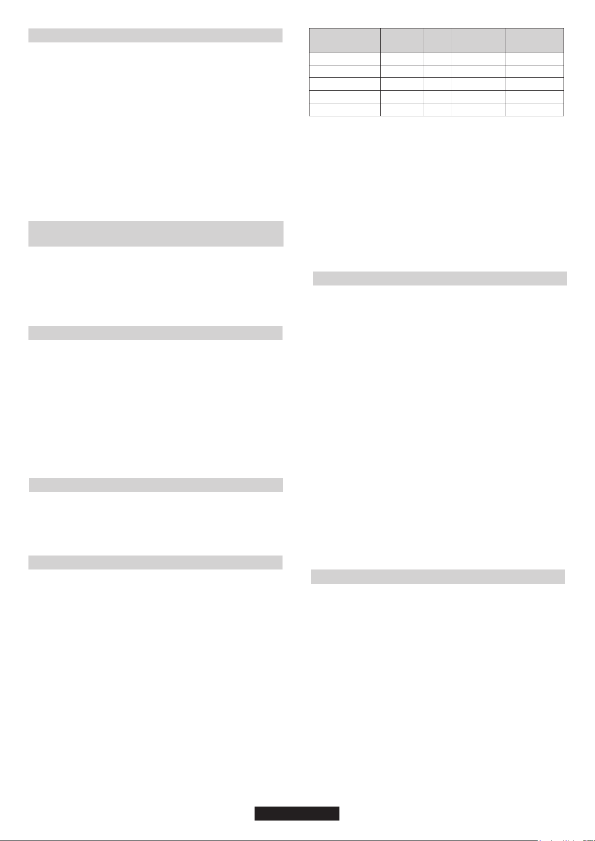
Gas Type
...............................................................................47
.....................................................................47
.............................................................................50-51-52
.................................................46
...................................................47
.............................................................47
..........................................................47
................................48
.......................................48
............................................................49
...............................49
...........................................................49
....................48
................48
Page 5
accessible space
C
A B
60 cm
75 cm
60 cm
Min 10 mm
Figure 2Figure 1
2
2
240 cm
Figure 3
Figure 5Figure 4
120 cm
180 cm
Sp.da 25 a 45 mm
2
2
1/2 GAS
CONICAL
CYLINDRICAL
CONICAL
Figure 8
Figure 6
INJECTOR
Figure 7
04 GB - IE
Page 6

SAFETY INSTURUCTIONS
WARNING: The appliance and its accessible parts become hot during use. Care should be taken to avoid
touching heating elements.
• Children under 8 Year of age must be kept away from the appliance unless they are continuously
supervised.
• This appliance can be used by children aged from 8 years and above and persons with reduced
physical, sensory or mental capabilities or lack of experience and knowledge if they have been given
supervision or instruction concerning use of the appliance in a safe way and understand the hazards
involved.
• Children must not play with the appliance.
• Cleaning and user maintenance shall not be made by children without supervision
WARNING: Unattended cooking on a hob with fat or oil can be dangerous and may result in fire.
• NEVER try to extinguish a fire with water, but switch off the appliance and then cover flame e.g. with a lid
or a fire blanket.
WARNING: Danger of fire: do not store items on the cooking surfaces.
WARNING: If the surface is cracked, switch off the appliance to avoid the possibility of electric shock.
• Do not use a steam cleaner for cleaning operations.
• Any spillage should be removed from the lid before opening.
• The hob surface must be allowed to cool down before closing the lid.
• This appliance is not intended to be operated by means of an external timer or separate remote-control
system.
• The means for disconnection must be incorporated in the fixed wiring in accordance with the wiring
rules.
• The instructions state the type of cord to be used, taking into account the temperature of the rear surface
of the appliance.
• If the supply cord is damaged, it must be replaced by a special cord or assembly available from the
manufacturer or its service agent.
CAUTION: In order to avoid a hazard due to inadvertent resetting of the thermal cutout, this appliance
must not be supplied through an external switching device, such as a timer, or connected to a circuit that
is regularly switched on and off by the utility.
• This appliance must be installed in accordance with the regulations in force and only used in a well
ventilated space. Read the instructions before installing or using this appliance.
• "These instructions are only valid if the country symbol appears on the appliance. If the symbol does not
appear on the appliance, it is necessary to refer to the technical instructions which will provide the
necessary instructions concerning modification of the appliance to the conditions of use of the country".
• "Prior to installation, ensure that the local distribution conditions (nature of the gas and gas pressure)
and the adjustment of the appliance are compatible";
• "The adjustment conditions for this appliance are stated on the label (or data plate)";
• "This appliance is not connected to a combustion products evacuation device. It shall be installed and
connected in accordance with current installation regulations. Particular attention shall be given to the
relevant requirements regarding ventilation".
• The use of a gas cooking appliance results in the production of heat and moisture in the room in which it
is installed. Ensure that the kitchen is well ventilated: keep natural ventilation holes open or install a
mechanical ventilation device (mechanical extractor hood). Prolonged intensive use of the appliance
may call for additional ventilation, for example opening of a window, or more effective ventilation, for
example increasing the level of mechanical ventilation where present.
05 GB
Page 7
1. INSTRUCTIONS FOR THE INSTALLER
INSTALLING A DOMESTIC APPLIANCE CAN BE A COMPLICATED OPERATION WHICH IF NOT CARRIED OUT CORRECTLY, CAN SERIOUSLY
AFFECT CONSUMER SAFETY. IT IS FOR THIS REASON THAT THE TASK SHOULD BE UNDERTAKEN BY A PROFESSIONALLY QUALIFIED
PERSON WHO WILL CARRY IT OUT IN ACCORDANCE WITH THE TECHNICAL REGULATIONS IN FORCE. IN THE EVENT THAT THIS ADVICE IS
IGNORED AND THE INSTALLATION IS CARRIED OUT BY AN UNQUALIFIED PERSON, THE MANUFACTURER DECLINES ALL RESPONSIBILITY
FOR ANY TECHNICAL FAILURE OF THE PRODUCT WHETHER OR NOT IT RESULTS IN DAMAGE TO GOODS OR INJURY TO INDIVIDUALS.
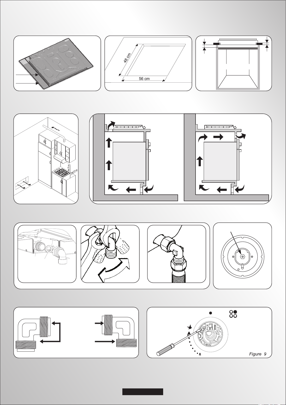
1.1 BUILDING IN
The hob may be installed in any worktop which is heat resistant to a
temperature of 100°C, and has a thickness of 25-45 mm. The
dimensions of the insert to be cut out of the worktop are in shown in
Figure 2.
If the Hob is fitted next to a cabinet on either side, the distance
between the Hob and the cabinet must be at least 15 cm (see Figure
4); while the distance between the hob and the rear wall must be at
least 5,5 cm.
The distance between the hob and any other unit or appliance above it
(e.g. An extractor hood) must be no less than 70 cm (Figure 4).
When there is an accessible space between the built-in hob and the
cavity below, a dividing wall made of insulating material should be
inserted (wood or a similar material) (Figure 3).
Important - The diagram in figure 1 shows how the sealant should
be applied.
The Hob unit is fitted by attaching the Fixing Clamps supplied, using
the holes at the base of the unit.
If a hob of 60 cm is fitted above an oven which is not equipped with fan
cooling system it is recommended that openings are created within
the built in furniture to ensure correct air circulation.
The size of these openings must be at least 300 cm2 and placed as
shown in Figure 5.
When a 75 cm hob is fitted over a built in oven, the latter must be fan
cooled.
1.2. SUITABLE LOCATION
This appliance must be installed in accordance with the regulations in
force and only used in a well ventilated space. Read the instructions
before installing or using this appliance.
A gas-powered cooking appliance produces heat and humidity in the
area in which it is installed. For this reason you should ensure good
ventilation either by keeping all natural air passages open or by
installing an extractor hood with an exhaust flue. Intensive and
prolonged use of the appliance may require extra ventilation, such as
the opening of a window or an increase in speed of the electric fan, if
you have one.
If a hood can not be installed, an electric fan should be fitted to an
outside wall or window to ensure that there is adequate ventilation.
The electric fan should be able to carry out a complete change of air in
the kitchen 3-5 times every hour. The installer should follow the
relevant national standards.
2.1. ELECTRICAL CONNECTION
Check the data on the rating plate, located on the outside of the unit, to
ensure that the supply and input voltage are suitable.
Before connection, check the earthing system.
By Law, this appliance must be earthed. If this regulation is not complied
with, the Manufacturer will not be responsible for any damage caused to
persons or property. If a plug is not already attached, fit a plug
appropriate to the load indicated on the rating plate. The earth wire is
coloured yellow/green. The plug should always be accessible.
Where the Hob is connected direct to the electricity supply, a circuit
breaker must be fitted.
If the power supply cord is damaged this is to be replaced by a qualified
engineer so as to prevent any potential risk.
The earth wire ( green and yellow coloured ) must be at least 10 mm
longer than the live and neutral wires.
The section of the cable used must be of the correct size in relation to
the absorbed power of the hob.
Please check rating plate for the power details and ensure that the
power supply cord is of the type 3x0.75 mm² H05RR-F.
LIVE
Mains Supply
If an appliance is not fitted with a supply cord and a plug, or with other
means for disconnection from the supply mains having a contact
separation in all poles that provide full disconnection under overvoltage
category III conditions, the instructions shall state that means for
disconnection must be incorporated in the fixed wiring in accordance with
the wiring rules.
When connecting the hob to the gas supply via use offlexible hoses
please ensure that the maximum distance covered by the hose does not
exceed 2 metres.
The flexible tube shall be fitted in such a way that it cannot come into
contact with a moveable part of the housing unit (e.g. a drawer) and does
not pass through any space where it may become crushed/ kinked or
damaged in any way.
To prevent any potential damage to the hob please carry out the
installation following this sequence (picture 6):
EARTH
NEUTRALLN
Brown Wire
Green/Yellow Wire
Blue Wire
Power Cable
2. ELECTRICAL CONNECTION (FOR U.K. ONLY)
Warning - this appliance must be earthed
This appliance is designed for domestic use only. Connection to the main
supply must be made by a competant electrician, ensuring that all current
regulations concerning such installations are observed.
The appliance must only be connected to a suitably rated spur point, a
3 pin 13 amp plug/socket is not suitable. A double pole switch must be
provided and the circuit must have appropriate fuse protection.
Further details of the power requirement of the individual product will
be found in the users’ instruction and on the appliance rating plate. In
the case of built-in product you are advised, should you wish to use a
longer cable than the one supplied, that a suitably rated heat resistant
type must be used.
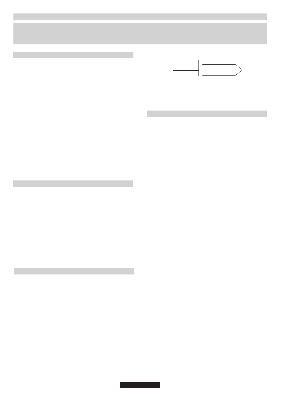
The wiring must be connected to the mains supply as follows:
CONNECT TO SPUR TERMINAL
Green & Yellow Wire Earth Connection
Blue Wire Neutral Connection
Brown Wire Live Connection
Note: We do not advocate the use of earth leakage devices with
electric cooking appliances installed to spur points because of the
«nuisance tripping» which may occur. You are again reminded that the
appliance must be correctly earthed, the manufacturer declines any
responsibility for any event occurring as a result of incorrect electrical
installation.
1)As illustrated, assemble parts in sequence:
A: 1/2 Male Adaptor Cylindirical
B: 1/2 Seal
C: 1/2 Female Gas Adaptor Conical-Cylindirical or
Cylindirical-Cylindirical
2)Tighten the joints with the spanner, remembering to twist the
pipes into position.
3)Attach fitting C to mains gas supply using rigid copper pipe or
flexible steel pipe.
IMPORTANT: carry out a final check for leaks on the pipe
connections using a soapy solution. NEVER USE A FLAME. Also,
make sure that the flexible pipe cannot come into contact with a
moving part of the cabinet (eg.adrawer) and that it is not situated
where it could be damaged.
Warning: If gas can be smelt in the vicinity of this appliance turn off the
gas supply to the appliance and call the engineer directly. Do not
search for a leak with a naked flame.
06 GB
Page 8
2.2. GAS CONNECTION
These instructions are for qualified personnel, installation of equipment
must be in line with the relevant national standard. (For U.K. only: by law
the gas installation\commissioning must be carried out by a "Gas
Safe" installer)
All work must be carried out with the electricity supply disconnected.
The rating plate on the hob shows the type of gas with which it is designed to
be used. Connection to the mains gas supply or gas cylinder should be
carried out after having checked that it is regulated for the type of gas with
which it will be supplied. If it is not correctly regulated see the instructions in
the following paragraphs to change gas setting.
For liquid gas (cylinder gas) use pressure regulators which comply with the
relevant national standards.
Use only pipes,washers and sealing washers which comply with the
relevant national standards.
For some models a conic link is furnished to outfit for the installation in the
countries where this type of link is obligatory; in picture 8 it is pointed out
how to recognize the different types of links (CY = cylindrical, CO = conic).
In every case the cylindrical part of the link has to be connected to the hob.
2.3. ADAPTING THE HOB TO DIFFERENT
TYPES OF GAS
To adapt the Hob for use with different types of gas, carry out the
following instructions:
•Remove the grids and burners
•Insert on hexagonal spanner (7 mm) into the burner support (Figure
7)
•Unscrew the injector and replace it with one suitable for the gas to be
used (see gas type table)
2.4. REGULATING THE MINIMUM FLAME
After lighting the burners, turn the control knob to the minimum setting
and then remove the knob (this can easily be removed by applying
gentle pressure).
Using a small «Terminal» type screwdriver the regulating screw can
be adjusted as in Figure 9. Turning the screw clockwise reduces the
gas flow, whilst turning it anticlockwise increases the flow – Use this
adjustment to obtain a flame of approximately 3 to 4 mm in length and
then replace the control knob.
When the gas supply available is LPG - the screw to set the idle flame
must be turned (clockwise) to the end stop.
When you have carried out the new gas regulation, replace the old gas
rating plate on your appliance with one (supplied with hob) suitable for
the type of gas for which it has been regulated.
3. USE OF HOB - USER INSTRUCTIONS
This appliance must only be used for the purpose for which it is
intended, domestic cooking, and any other use will be considered
improper and could therefore be dangerous. The Manufacturer will
not be responsible for any damage or loss resulting from improper
use.
Burner Type
AUX
Auxiliary
SR
Semi Rapid
R
Rapid
UR
Ultra Rapid
QC
Double Ring
For smaller containers the gas burner should be regulated so that the
flame does not overlap the base of the pan. Vessels with a concave or
convex base should not be used.
WARNING: If a flame is accidentally extinguished, turn the knob
to the off position and do not attempt to re-ignite if for at least 1
minute.
If over the years the gas taps become stiff to turn it is necessary to
lubricate them.
Such operation must be carried out only by qualified Service
Engineers.
Ø pan/pot
(cm)
12 - 18
18 - 24
24 - 26
24 - 28
24 - 28
Power
(kW)
1,00
1,75
2,50
3,50
4,00
G20/20 mbar
(methane)
95 l/h
167 l/h
238 l/h
333 l/h
381 l/h
G30/28-30 mbar
(LPG)
73 g/h
127 g/h
182 g/h
255 g/h
291 g/h
Table A
4. MAINTENANCE AND CLEANING
Before cleaning the hob, ensure the appliance has cooled down.
Remove the plug from the socket or (if connected directly) switch off
the electricity supply.
Cleaning and user maintenance shall not be made by children without
supervision
Never use abrasives, corrosive detergents, bleaching agents or
acids. Avoid any acid or alkaline substances (lemon, juice, vinegar
etc.) on the enamelled, varnished or stainless steel sections.
When cleaning the enamelled, varnished or chrome sections, use
warm soapy water or a non caustic detergent. For stainless steel use
an appropriate cleaning solution.
The burners can be cleaned with soapy water. To restore their original
shine, use a household stainless steel cleaner. After cleaning, dry the
burners and replace.
It is important the Burners are replaced correctly.
Chromed grids and burners
Chromed grids and burners have a tendency to discolour with use.
This does not jeopardize the functionality of the hob.
Our After Sales Service Centre can provide spare parts if required.
3.1. USING THE GAS BURNER
To ignite the burners, place a lighted taper close to the burner, press in
and turn the control knob anti-clockwise.
If the burners have not been used for a couple of days, wait for a few
seconds before lighting the burner, this will allow any air present in the
pipes to escape.
For appliances fitted with electronic ignition carry out the following:
• Push in and turn the knob anticlockwise to the ignition symbol.
• İgnite the burner by pressing the sparker button.
For hobs fitted with automatic ignition simply push in and turn the knob
to the ignition symbol.
The ignition system will continue to generate sparks as long as the
control knob is being pressed.
If the burner has not ignited within 5 seconds, turn the knob to the 0
position and repeat the operation.
For models fitted with a safety tap (which cuts-off the flow of gas if the
flame is accidentally extinguished) the burners are ignited and
described above, but care must be taken.
Prior to switching on the gas hob ensure that the burners and burner
caps are correctly placed within their position.
GENERAL ADVISE
For best results, use cooking vessels with a flat surface. The size of
the surface should match the gas burner side as follows. Table A.
5. AFTERCARE
Before calling out a Service Engineer please check the following:
• that the plug is correctly inserted and fused;
• that the gas supply is not faulty.
If the fault cannot be detected:
Switch off the appliance and call the After Service Centre. DO NOT
TAMPER WITH THE APPLIANCE.
07 GB
Page 9
6. PROTECTION OF THE ENVIRONMENT
This appliance is marked according to the European
directive 2012/19/EU on Waste Electrical and
Electronic Equipment (WEEE). WEEE contains both
polluting substances (which can cause negative
consequences for the environment) and basic
components (which can be re-used). It is important to
have WEEE subjected to specific treatments, in order
recover and recycle all materials.
Individuals can play an important role in ensuring that WEEE does not
become an environmental issue; it is essential to follow some basic
rules:
• WEEE shall not be treated as household waste.
• WEEE shall be handed over to the relevant collection points
managed by the municipality or by registered companies. In many
countries, for large WEEE, home collection could be present.
• When you buy a new appliance, the old one may be returned to the
retailer who has to collect it free of charge on a one-to-one basis, as
long as the equipment is of equivalent type and has the same
functions as the supplied equipment.
Declaration of compliance: This equipment, in the parts intended to
come into contact with food, complies with the regulations laid down in
EEC directives 89/109.
Appliance complies with European Directives 2006/95/EC,
2004/108/EC and 2009/142/EC, and subsequent amendments.
The Manufacturer will not be responsible for any inaccuracy resulting
from printing or transcript errors contained in this brochure. We
reserve the right to carry out modifications to products as required,
including the interests of consumption, without prejiudice to the
characteristics relating to safety or function.
to remove and dispose properly all pollutants, and
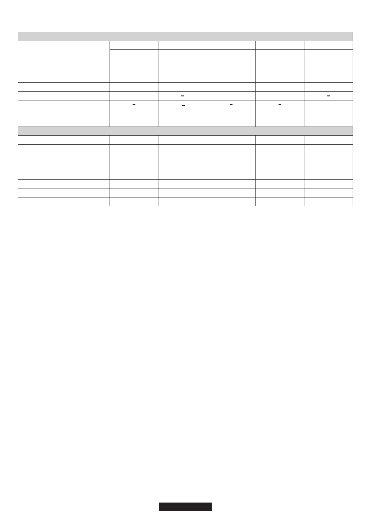
BUILT IN HOBS
1
Burner
Type / reference
Flame failure device
Auxiliary burner ( AUX Ø 50 mm)
Double ring burner ( QC Ø 135 mm)
Ultra rapid burner ( UR Ø 110 mm)
Semirapid burner ( SR Ø 75 mm)
Rapid burner ( R Ø 100 mm)
Installed Gas Type / Power:
Power
G 20/20 mbar (methane)
G 30/28-30 mbar (LPG)
Installation Class
Voltage / Frequency V / Hz
Electrical input power
Electric ignition
Product dimension
This appliance has been designed for non-professional, i.e. domestic, use.
4 gas
QC / R / SR / AUX
S67 / HBGPL2X
YES
1
1
1
1
9.25 kW
881 L/h
673 g/h
3
220-240 V / 50-60 Hz 220-240 V / 50-60 Hz 220-240 V / 50-60 Hz 220-240 V / 50-60 Hz
15 W
YES
595 x 510
1
4 gas
R / 2SR / AUX
S67 / HBGPL2X
YES
1
2
1
7.00 kW
666 L/h
509 g/h
3
15 W
YES
595 x 510
2
5 gas
QC / 2R / SR / AUX
S67 / HBGPL2X
YES
1
1
1
2
11.75 kW
1119 L/h
854 g/h
3
15 W
YES
745 x 510
3
4 gas
QC / R / SR / AUX
S67 / HBGPL2X
YES
1
1
1
1
9.25 kW
881 L/h
673 g/h
3
15 W
YES
745 x 510
Table 1
2
5 gas
UR / 2R / SR / AUX
S67 / HBGPL2X
YES
1
1
1
1
11.25 kW
1071 L/h
818 g/h
3
220-240 V / 50-60 Hz
15 W
YES
745 x 510
08 GB
Page 10

CONSEILS DE SÉCURITÉ
AVERTISSEMENT: L'appareil et les parties accessibles deviennent chauds pendant l'utilisation. Des
précautions doivent être prises pour éviter de toucher les éléments chauffants.
• Les enfants de moins de 8 ans doivent être tenus à l'écart à moins d'être surveillés continuellement.
• Cet appareil n'est pas destiné à être utilisé par des personnes (y compris les enfants) dont les capacités
physiques, sensorielles ou mentales sont réduites, ou ayant un manque d'expérience et de
connaissances, à moins qu'elles n'aient été formées à l'utilisation de l'appareil, par une personne
responsable de leur sécurité.
• Les enfants ne doivent jouer avec l'appareil.
• Le nettoyage et l'entretien par l'utilisateur ne doit pas être fait par des enfants sans surveillance.
ATTENTION: La cuisson sans surveillance sur une plaque de cuisson avec de la graisse ou d'huile peut
être dangereuse et peut entraîner un incendie.
• Ne jamais tenter d'éteindre un incendie avec de l'eau, mais éteindre l'appareil, puis couvrir la flamme
par exemple avec un couvercle ou une couverture anti-feu.
AVERTISSEMENT: Danger d'incendie: ne pas stocker des éléments sur les surfaces de cuisson.
ATTENTION: Si la surface est fêlée, éteindre l'appareil pour éviter les risques de choc électrique.
• Ne pas utiliser de nettoyants vapeur pour le nettoyage.
• Tout liquide doivent être enlevé du couvercle avant ouverture.
• Il est recommandé de laisser refroidir la table de cuisson avant de refermer le couvercle.
• l'appareil n'est pas destiné à être utiliser avec une minuterie externe ou un système de contrôle à
distance.
• Un système de déconnexion doit être incorporé dans le compteur conformément aux règles de
câblage.
• Les instructions ndiquent le type de cordon à utiliser, en tenant compte de la température de la surface
arrière de l'appareil.
• Si le cordon d'alimentation est endommagé, il doit être remplacé par un cordon spécial disponible
auprès du fabricant ou de stations de dépannage agrées.
ATTENTION: Pour éviter tout danger dû à une réinitialisation accidentelle, cet appareil ne doit pas être
alimenté par un dispositif de commutation externe, comme une minuterie, ou connecté à un circuit qui est
régulièrement allumé et éteint par l'utilitaire.
• Cet appareil doit être installé en conformité avec la réglementation en vigueur et utilisé uniquement
dans un espace ventilé. Lisez les instructions avant d'installer ou utiliser cet appareil.
• Ces instructions ne sont valables que si le symbole du pays apparaît sur l'appareil. Si le symbole
n'apparaît pas sur l'appareil, il est nécessaire de se référer à la notice technique qui fournira les
instructions nécessaires concernant la modification de l'appareil selon les conditions d'utilisation du
pays.
• Avant l'installation, s'assurer que les conditions de distribution locale (la nature du gaz et la pression) et
le réglage de l'appareil sont compatibles"
• Les conditions de réglage de cet appareil sont indiqués sur l'étiquette (ou données de la plaque) ;
• "Cet appareil n'est pas relié à un dispositif d'évacuation des produits de combustion. Il doit être installé
et raccordé conformément aux règles d'installation en cours. Une attention particulière doit être
accordée aux exigences concernant la ventilation ".
• "Les résultats de la table gaz dans la production de chaleur depend de l'humidité dans la pièce dans
laquelle elle est installé Veiller à ce que la cuisine soit bien ventilée. Laissez les ouvertures de ventilation
naturelle ouvertes ou installez un dispositif de ventilation mécanique (hotte aspirante mécanique). Une
utilisation intensive prolongée de l'appareil peut faire appel à l'utilsation d'une ventilation
supplémentaire, par exemple d'ouverture d'une fenêtre, ou plus efficace de ventilation mécanique, par
exemple en augmentant le niveau de la ventilation mécanique présent.
09 FR
Page 11
1. INSTALLATION
La mise en place fonctionnelle des appareils ménagers dans leur environnement est une opération délicate qui, si elle n'est pas correctement
effectuée, peut avoir de graves conséquences sur la sécurité des consommateurs. Dans ces conditions, il est impératif de confier cette tâche à
un professionnel qui la réalisera conformément aux normes techniques en vigueur. Si malgré cette recommandation, le consommateur
réalisait lui-même l'installation, le constructeur déclinerait toute responsabilité en cas de défaillance technique du produit entraînant ou non
des dommages aux biens et/ou aux personnes.
1.1. ENCASTREMENT
Le meuble ou le support dans lequel doit être encastrée la table, ainsi
que les parois du meuble qui pourraient juxtaposer celui-ci, doivent
être d'une matière résistant à une température élevée (jusqu'à 100°C)
et d'une épaisseur comprise entre 25 et 45 cm.
Les dimensions d'encastrement sont indiquées sur le schéma 2.
Si la table est installée entre deux meubles de cuisine, la distance
entre la table et les meubles doit être au moins de 15 cm (voir schéma
4); tandis que la distance entre la table et le mur du fond doit être au
moins de 5,5 cm. La distance entre la table et tout autre appareil ou
meuble situé au dessus (par exemple une hotte) doit être au moins de
70 cm (voir schéma 4).
Si, en fonction de l'installation de la table, la partie inférieure de son
caisson se trouve à proximité d'une zone normalement accessible
lors de manipulations et/ou de rangements, placer une cloison (bois
ou similaire) pour éviter tous risques de brûlure ou de détérioration
(schéma 3).
Attention : Lors de la mise en place, un soin particulier doit être
porté au joint entourant le bord de la table afin d'éviter toute
infiltration dans le meuble support (schéma 1).
Lors de la mise en place du joint sur la partie arrière, veiller à ne pas
obstruer les passages d'air nécessaires à la combustion.
Le caisson de la table est équipé en dessous de 4 emplacements
prévus pour recevoir les brides de fixation destinées à l'immobilisation
de la table sur le meuble. Placer les 4 brides de fixation de manière à
ce que la table de travail soit parfaitement plaquée au meuble.
Si une table de 60 cm de large est installée au-dessus d'un four qui
n'est pas équipé de ventilation tangentielle, il est recommandé de
créer des ouvertures dans le caisson de cuisine pour faire ainsi
circuler l'air.
La taille de ces ouvertures doit être au moins de et placées 300 cm²
comme indiqué sur le schéma 5.
Si c'est une table de 75cm de large qui est installée au-dessus du four,
ce dernier doit être équipé d'une ventilation tangentielle.
1.2. CARACTERISTIQUES REQUISES
Cet appareil doit être installé en conformité avec la réglementation en
vigueur et utilisé uniquement dans un espace ventilé. Lisez les
instructions avant d'installer ou utiliser cet appareil.
Une utilisation intensive et prolongée de l'appareil peut requérir une
ventilation plus importante, telle que l'ouverture d'une fenêtre ou une
puissance d'aspiration plus intense de la VMC si vous en êtes
équipés.
S'il n'est pas possible d'installer une hotte, une VMC devrait être
installée sur un mur donnant sur l'extérieur ou sur une fenêtre.
La VMC devrait être en mesure d'apporter un changement complet de
l'air de la cuisine 3 à 5 fois par heure. L'installateur doit installer la VMC
conformément aux règles en vigueur dans le pays d'installation.
2.1. RACCORDEMENT ELECTRIQUE
"L'installation recevant l'appareil cité en référence doit être
conforme à la norme en vigueur dans le pays d'installation".
Le constructeur décline toute responsabilité en cas de non
respect de cette disposition.
Vérifier les données sur la plaque signalétique, située à l'extérieur de
l'unité, pour assurer que l'alimentation et le voltage conviennent.
Avant le branchement, vérifier le système de mise à la terre.
Attention : vérifier la continuité de la terre de l'installation avant
de procéder au raccordement. Notre responsabilité ne saurait
être engagée pour tout incident ou ses conséquences
éventuelles qui pourraient survenir à l'usage d'un appareil non
relié à la terre, ou relié à une terre dont la continuité serait
défectueuse.
Si une prise n'est pas déjà fournie, installer une prise appropriée pour
la charge indiquée sur la plaque signalétique.
La prise devrait toujours être accessible.
Le fil de terre est de couleur jaune / vert.
Lorsque la table de cuisson est r eliée directement à
l'approvisionnement en électricité, un disjoncteur doit être installé.
Si le cordon d'alimentation est endommagé, il doit être remplacé par
un technicien qualifié afin d'éviter tout risque potentiel.
Le fil de terre (couleur vert et jaune) doit être au moins 10mm plus long
que les fils de phase et neutre.
La section du câble utilisé doit être de la bonne taille par rapport à la
puissance absorbée de la table de cuisson.
Veuillez vérifier la plaque signalétique pour les détails de puissance et
veiller à ce que le cordon d'alimentation électrique soit de type 3x0.75
mm² l'H05RR F.
PHASE
Alimentation
Un système de déconnexion doit être incorporé dans le compteur
conformément aux règles de câblage.
TERRE
NEUTRELN
Fil Marron
Fil Vert/jaune
Fil Bleu
2.2. RACCORDEMENT GAZ
L'appareil doit être installé et raccordé conformément aux règles
En vigueur dans le pays d'installa-tion. Une attention
particulière sera accordée aux dispositions applicables en matière
De ventilation.
Tous les travaux d'installation doivent être effectués avec l'électricité
déconnectée.
La plaque signalétique sur la plaque indique le type de gaz qui doit
être utilisé. Le raccordement au réseau d'approvisionnement en gaz
cylindre doit être effectuée qu'après avoir vérifié qu'il est réglementé
pour le type de gaz avec lequel il sera distribué. S'il n'est pas
correctement réglementé, voir les instructions dans les paragraphes
suivants pour modifier les paramètres du gaz.
Pour le gaz liquide (bouteille de gaz), utiliser des régulateurs de
pression conformes aux normes en vigueur.
Utilisez uniquement des tuyaux, des rondelles et des rondelles
d'étanchéité conformes aux normes en vigueur.
Pour certains modèles un lien conique est fourni pour installation
l'appareil, dans les pays où ce type de lien est obligatoire ; sur le
schéma 8, il est indiqué comment reconnaître les différents types de
liens (CY = cylindrique, CO = conique). Dans tous les cas, la partie
cylindre du lien doit être connecté à la table.
Lorsque vous connectez la table de cuisson à l'alimentation du gaz via
l'utilisation de tuyaux flexibles, veuillez faire en sorte que la distance
maximum couverte par le tuyau ne dépasse pas 2 mètres.
Le tube flexible doit être installé de manière à ne pas entrer en contact
avec un élément mobile de la cuisine (par exemple un tiroir) et à ne
pas passer dans un espace pouvant être encombré.
Pour éviter tout dommage potentiel à la table de cuisson, veuillez
effectuer l'installation suivant les indications du schéma 6.
1) Comme illustré dans le schéma, assembler les pièces en
séquence :
A: ½ Adaptateur Cylindrique mâle
B: ½ Obturation
C: ½ Adaptateur gaz Femelle conique-cylindrique ou cylindriquecylindrique.
2) Serrer les joints avec des clés à molette, pensez à placer les
tuyaux en position.
3) Fixer le raccord C au réseau d'approvisionne-ment en gaz à
l'aide tuyau rigide ou en acier flexi-ble.
IMPORTANT: effectuer une dernière vérification pour détecter
les fuites sur les raccords de tuyauterie en utilisant une solution
savonneuse. Ne jamais utiliser une flamme. Aussi, assurez vous
que le tuyau flexible ne peut pas entrer en contact avec une
partie mobile du meuble de cuisine (par exemple un tiroir) et qu'il
ne se trouve pas à un endroit où il pourrait être endommagé.
Attention: Si vous sentez des émanations de gaz en provenance de
l'appareil, coupez immédiatement l'alimentation en gaz et appelez
directement une personne qualifiée. Ne cherchez pas une fuite à
l'aide d'une flamme.
10 FR
Câble
lectriqueé
d’alim
Page 12
2.3. ADAPTER LA TABLE A DIFFERENTS
TYPES DE GAZ
Pour adapter la table de cuisson à différents types de gaz, veuillez
exécuter les instructions suivantes:
• Enlever les grilles, chapeaux et corps de brûleurs
• Insérez une clé à pipe (7 mm) dans le support du brûleur (schéma 7)
• Dévisser le/les injecteurs et le/les remplacer par un/des injecteurs
adaptés au gaz à utiliser (voir le type de gaz préconisé sur la table)
• Visser le/les injecteurs à fond
• Régler la bague d'air
• Replacer les corps de brûleurs, le chapeau de brûleur et les grilles.
Type de brûleurs
A
Brûleur auxiliaire
SR
Brûleur semi-rapide
R
Brûleur rapide
UR
Brûleur ultra rapide
QC
Brûleur quadruple
couronne
Ø casserole
(cm)
12 - 18
18 - 24
24 - 26
24 - 28
24 - 28
Puissance
totale
(kW)
1,00
1,75
2,50
3,50
4,00
G20/20 mbar
(Gaz de naturel :
Méthane)
95 I/h
167 I/h
238 I/h
333 I/h
381 I/h
G30/28-30 mbar
(Butane/Propane)
73 g/h
127 g/h
182 g/h
255 g/h
291 g/h
Table A
2.4. REGULER LA FLAMME AU MINIMUM
Après l'allumage du brûleur, tourner le bouton de commande au
réglage minimum, puis enlever la manette de commande (ce qui
peut facilement être enlevé par appliquer une légère pression).
En utilisant un petit «Terminal » type tournevis, la vis de réglage peut
être ajustée (cf Schéma 9). En tournant la vis dans le sens des
aiguilles d'une montre, cela réduit le débit de la flamme, alors qu'en
tournant dans le sens inverse, cela l'augmente. Utilisez ce réglage
pour obtenir une flamme d'environ 3 à 4 mm de longueur, puis
replacer la manette de commande.
Lorsque l'approvisionnement en gaz disponible est du
butane/propane (gaz de bouteilles), la vis pour régler la flamme au
ralenti doit être tournée dans le sens des aiguilles d'une montre,
jusqu'à la butée.
Lorsque vous avez effectué la régulation du gaz, remplacer
l'ancienne plaque signalétique de votre appareil avec celle adaptée
au type de gaz installé (fournie avec plaque de cuisson).
3. UTILISATION DE LA TABLE
Cet appareil ne doit être utilisé que pour des fins pour lesquelles il est
destiné : la cuisson domestique. Toute autre utilisation sera
considérée comme abusive et peut donc être dangereuse. Le
fabricant ne sera pas responsable pour tout dommage ou perte
découlant d'une utilisation abusive.
3.1. USING THE GAS BURNER
Pour allumer les brûleurs, placez une flamme (allume-feu, allumette,
briquet etc…) près du brûleur, appuyez et tournez la manette de
commande.
Si les brûleurs n'ont pas été utilisés depuis quelques jours, attendre
quelques secondes avant d'allumer le brûleur, ce qui permettra l'air
éventuellement présent dans les tuyaux de s'échapper.
Pour les appareils équipés d'allumage électronique, effectuer les
opérations suivantes:
• Pousser et tourner la manette de commande sur le symbole
d'allumage.
• Allumer le brûleur en appuyant sur le bouton d'allumage
Pour les tables de cuisson équipées d'allumage électronique intégré,
il suffit de pousser et tourner le bouton sur le symbole d'allumage.
Le système d'allumage continuera à produire des étincelles aussi
longtemps que le robinet de gaz est actionné.
Si le brûleur ne s'enflamme pas dans les 5 secondes, tournez le
bouton vers la position 0 et répéter l'opération.
Pour les modèles équipés d'un robinet de sécurité par thermocouple
(qui coupe l'écoulement du gaz si la flamme est accidentellement
éteint), les brûleurs sont allumés et décrit ci-dessus, mais il faut
prendre soin de garder la manette de commandes enfoncée pendant
5 ou 6 secondes après que la flamme est allumée.
Pour les petites casseroles/poêles, le brûleur à gaz doit être réglé de
telle manière que la flamme ne chevauche pas le fond de la casserole.
Les récipients à fond concave ou convexe ne doivent pas être utilisés.
ATTENTION: Si un brûleur est accidentellement éteint, tournez le
bouton vers la position fermée et ne pas tenter de relancer
pendant au moins 1 minute.
Si au fil des années les robinets de gaz deviennent raides, il est
nécessaire de les lubrifier.
Cette opération doit être effectuée que par un technicien agréé.
4. MAINTENANCE ET ENTRETIEN
Avant de nettoyer la table de cuisson, assurez-vous que cet appareil
est refroidi. Retirez la fiche de la prise ou (s'il est connecté
directement), éteindre l'alimentation d'électricité.
Le nettoyage et l'entretien par l'utilisateur ne doit pas être fait par des
enfants sans surveillance.
Ne jamais utiliser de produits abrasifs, de détergents corrosifs, agents
de blanchiment ou d'acides. Éviter les substances acides ou alcalines
(citron, jus, vinaigre etc…) sur l'émail ou l'acier.
Lors du nettoyage de l'émail, vernis ou des sections chromées,
utilisez de l'eau chaude savonneuse ou un détergent non corrosif.
Pour l'acier inoxydable, utilisez une solution de nettoyage appropriée.
Les brûleurs peuvent être nettoyés avec de l'eau savonneuse. Pour
restaurer leur éclat d'origine, utilisez un nettoyant ménager pour acier
inoxydable. Après nettoyage, séchez les brûleurs et les replacer.
Il est important que les brûleurs soient remplacés correctement
à leur position.
Grilles chromées et brûleurs
Les grilles chromées et les brûleurs ont tendance à foncer à
l'utilisation. Il s'agit d'un phénomène normal et inévitable, mais elle ne
compromet pas la fonctionnalité de la table de cuisson.
Si besoin, des pièces de rechange sont disponibles dans notre centre
de service après-vente.
5. ASSISTANCE TECHNIQUE
Avant d'appeler le Service d'Assistance Technique, vérifier les points
suivants:
• La prise est bien insérée ;
• L'approvisionnement en gaz n'est pas défectueux.
Si la panne ne peut être identifiée:
Éteignez l'appareil (ne pas l'utiliser) et appeler le Service d'Assistance
Technique.
ATTENTION : Avant d'allumer la table gaz, veillez à ce que les
brûleurs et les chapeaux de brûleur soient correctement placés dans
leur position.
CONSEIL
Pour de meilleurs résultats, la taille de casseroles à fond plat doit
correspondre à la taille des brûleurs comme suit :
11 FR
Page 13
6. PROTECTION DE L'ENVIRONNEMENT
Le présent appareil est marqué conformément à la directive
polluantes, puis de récupérer et recycler tous les matériaux.
Chacun peut jouer un rôle important quant à la protection de
l'environnement contre les DEEE. Pour atteindre cet objectif, il est
impératif de suivre quelques règles élémentaires :
• Les DEEE ne doivent pas être traités comme des déchets
ménagers.
• Ils doivent être remis aux points de collecte appropriés gérés par la
municipalité ou par des sociétés immatriculées. Dans plusieurs pays,
il est possible de collecter à domicile les DEEE volumineux.
• Lorsque vous achetez un nouvel appareil, vous devez retourner
l'ancien au vendeur qui le récupère gratuitement, au cas par cas, à
condition que l'équipement soit de type équivalent et possède les
mêmes fonctions que celui fourni.
L'appareil est conforme aux directives européennes 2006/95/EC,
2004/108/EC et 2009/142/EC, et ses modifications ultérieures.
2012/19/UE relative aux déchets d'équipements
électriques et électroniques (DEEE). Les DEEE
contiennent à la fois des substances polluantes (qui
peuvent avoir des conséquences négatives sur
l'envi ronnement) et des éléments de base
(réutilisables). Il est important de soumettre les DEEE
à des traitements spécifiques, en vue d'extraire et
d'éliminer de façon appropriée toutes les substances
Déclaration de conformité: cet équipement, dans les parties
destinées à entrer en contact avec les aliments, est conforme
aux normes fixées par les directives CEE 89/109.
Le constructeur décline toute responsabilité concernant
d'éventuelles inexactitudes imputables à des erreurs d'impression ou
de transcription contenue dans cette notice. Le constructeur se
réserve le droit de modifier les produits en cas de nécessité, même
dans l'intérêt de l'utilisation, sans causer de préjudices aux
caractéristiques de fonctionnement de sécurité des appareils.
TABLES DE CUISSON
1
Foyers
Modèle
Sécurité gaz par thermocouple
Brûleur auxiliaire (AØ 50 mm)
Brûleur quadruple couronne (QC Ø 135 mm)
Brûleur ultra rapide (UR Ø 110 mm)
Brûleur semi-rapide (SR Ø 75 mm)
Brûleur rapide (R Ø 100 mm)
Type de gaz installé / Puissance :
Puissance totale
G 20/20 mbar (Gaz de naturel : Méthane)
G 30/28-30 mbar (Butane/Propane)
Classe d'installation
Voltage / Frequency V / Hz
Puissance électrique
Allumage électronique intégré
Dimensions appareil (LxP) mm
Cet appareil a été dessiné pour un usage non professionnel, usage domestique uniquement
4 gaz
QC / R / SR / AUX
S67 / HBGPL2X
YES
1
1
1
1
9.25 kW
881 L/h
673 g/h
3
220-240 V / 50-60 Hz 220-240 V / 50-60 Hz 220-240 V / 50-60 Hz 220-240 V / 50-60 Hz
15 W
YES
595 x 510
1
4 gaz
R / 2SR / AUX
S67 / HBGPL2X
YES
1
2
1
7.00 kW
666 L/h
509 g/h
3
15 W
YES
595 x 510
5 gaz
QC / 2R / SR / AUX
S67 / HBGPL2X
YES
11.75 kW
1119 L/h
854 g/h
15 W
YES
745 x 510
12 FR
Table 1
2
QC / R / SR / AUX
1
1
1
2
3
3
4 gaz
UR / 2R / SR / AUX
S67 / HBGPL2X
YES
1
1
1
1
9.25 kW
881 L/h
673 g/h
3
220-240 V / 50-60 Hz
15 W
YES
745 x 510
2
5 gaz
S67 / HBGPL2X
YES
1
1
1
1
11.25 kW
1071 L/h
818 g/h
3
15 W
YES
745 x 510
Page 14

BEZPEČNOSTNÍ POKYNY
UPOZORNĚNÍ: Spotřebič a jeho přístupné části se během použití zahřívají. Nedotýkejte se topných
prvků.
• Děti do 8 let držte mimo dosah spotřebiče, pokud nejsou neustále pod dohledem.
• Tento spotřebič smí používat děti starší 8 let a osoby se sníženými fyzickými, senzorickými nebo
mentálními schopnostmi nebo bez dostatečných zkušeností, pokud jsou pod dohledem a byly poučeny o
použití spotřebiče a možném riziku.
• Nedovolte dětem hrát si se spotřebičem.
• Čištění a údržbu nesmí provádět děti bez dohledu.
UPOZORNĚNÍ: Vaření na desce s tuky a oleji bez dohledu je nebezpečné a může způsobit požár.
• NIKDY se nepokoušejte uhasit plamen vodou, vypněte spotřebič a poté překryjte plamen pokličkou
nebo protipožární přikrývkou.
UPOZORNĚNÍ: Pokud je povrch varné desky prasklý, spotřebič vypněte, abyste zabránili riziku
zasažení elektrickým proudem.
• K čištění nepoužívejte vysokotlaké parní čističe.
• Nečistoty z krytu odstraňte před otevřením.
• Varnou desku nechte před zavřením krytu vychladnout.
• Spotřebič nesmíte ovládat pomocí externího časovače nebo samostatného dálkového ovládání.
• Odpojovací zařízení musí být včleněno do napájení v souladu s platnými předpisy.
• Pokud je poškozený přívodní kabel, musíte jej vyměnit za speciální kabel dostupný u výrobce nebo
servisního technika.
UPOZORNĚNÍ: abyste zabránili nebezpečí z neúmyslného resetování tepelné pojistky, tento spotřebič
nesmíte napájet přes externí spínací zařízení, jako je časovač, nebo připojovat k obvodu, který se
pravidelně zapíná a vypíná elektrikářskou službou.
•Tento spotřebič musí být instalován v souladu s platnými předpisy a používat na dobře větraném místě.
Před instalací a použitím spotřebiče si přečtěte pokyny k použití.
• "Tyto pokyny platí pouze v případě, pokud je symbol země uvedený na spotřebiči. Pokud není, je nutné
prostudovat si technické instrukce, týkající se příslušných změn spotřebiče podle dané země".
• "Před instalací se ujistěte, zda místní napájecí podmínky (typ plynu a tlak plynu) a nastavení spotřebiče
odpovídají";
• "Podmínky nastavení tohto spotřebiče jsou uvedeny na výrobním štítku";
• "Tento spotřebič není připojený k systému odvodu spalin. Musí být instalován a připojován v souladu s
platnými instalačními předpisy. Zvyšte pozornost na příslušné požadavky týkající se ventilace".
• "Použití plynových varných spotřebičů způsobuje tvorbu tepla a vlhkosti v místnosti, kde je spotřebič
instalován. Ujistěte se, zda je kuchyň dobře větraná: udržujte přirozené větrací otvory volné nebo
instalujte mechanické větrací zařízení (odsavač par). Dlouhodobé intenzivní použití spotřebiče může
vyžadovat další větrání, například otevření dveří nebo okna, nebo efektivnější větrání, například
zvýšením úrovně mechanické ventilace".
UPOZORNĚNÍ: Riziko požáru: neskladujte žádné předměty na varné desce.
13 CZ
Page 15
1. POKYNY PRO INSTALATÉRA
INSTALACE DOMÁCÍCH SPOTŘEBIČŮ MŮŽE BÝT SLOŽITÁ OPERACE, KTERÁ, POKUD NENÍ PROVEDENA SPRÁVNĚ, MŮŽE VÁŽNĚ
OHROZIT BEZPEČNOST UŽIVATELE. Z TOHOTO DŮVODU POŽÁDEJTE O INSTALACI KVALIFIKOVANÉHO SERVISNÍHO TECHNIKA,
KTERÝ INSTALACI PROVEDE PODLE PLATNÝCH PŘEDPISŮ. V PŘÍPADĚ NEOPRÁVNĚNÉ INSTALACE VÝROBCE NENESE ŽÁDNOU
ODPOVĚDNOST ZA TECHNICKÉ ZÁVADY VÝROBKU, KTERÉ MOHOU VÉST KE POŠKOZENÍ VÝROBKU NEBO ZRANĚNÍ OSOB.
1.1 VESTAVBA
Varnou desku lze instalovat do pracovní desky, která je z teplu
odolného materiálu do 100°C a má tloušťku 25-45 mm. Rozměry
výřezu v pracovní desce jsou na obrázku 2.
Pokud je varná deska připevněná k nábytku na kterékoli straně,
vzdálenost mezi varnou deskou a nábytkem musí být nejméně 15 cm
(viz obrázek 4); zatímco vzdálenost mezi varnou deskou a zadní
stěnou musí být nejméně 5,5 cm.
Vzdálenost mezi varnou deskou a spotřebičem nad ní (např. odsavač
par) musí být nejméně 70 cm (obrázek 4).
Pokud není volný prostor mezi varnou deskou a skříňkou pod ní, je
nutné instalovat vhodné mezidno (dřevěné nebo z podobného
materiálu) (obrázek 3).
Důležité - Obrázek 1 znázorňuje aplikaci těsnění.
Varná deska se upevňuje pomocí dodaných upevňovacích svorek,
pomocí otvorů ve spodní části spotřebiče.
Pokud je 60 cm varná deska nad troubou, která není vybavená
chladicím ventilátorem, doporučujeme udělat větrací otvory v nábytku
pro zajištění správné ventilace.
Velikost otvorů musí být nejméně 300 cm2 a umístění podle obrázku
5.
Pokud je 75 cm varná deska nad troubou, musí být přidán chladicí
Ventilátor.
Živý
Napájení
Pokud spotřebič není vybaven přívodním kabelem se zástrčkou, nebo
jiným typem odpojovacího ařízení nabízejícím odstup kontaktu v
odpojeném stavu podle požadavků proti přepětí III kategorie, musíte
uskutečnit toto připojení podle platných směrnic.
Uzemnění
Neutrální
2.2. PŘIPOJENÍ PLYNU
Tyto pokyny jsou pro kvalifikovaného technika, instalace musí být v
souladu s národními předpisy.
Všechny práce se musí provádět při odpojeném napájení.
Výrobní štítek na varné desce definuje typ plynu, pro který je
navržená. Připojení k hlavní přípojce plynu nebo k plynové láhvi může
být provedeno po ověření, že je vhodný pro typ přiváděného plynu.
Pokud není správně regulovaný, viz pokyny v následujících
odstavcích pro úpravu nastavení.
Pro tekutý plyn (plyn v láhvi) použijte regulátor tlaku plynu vyhovující
mezinárodním standardům.
Hnědý vodič
L
Zelenožlutý vodič
Modrý vodič
N
Přívodní
kabel
1.2 VHODNÉ MÍSTO INSTALACE
Tento spotřebič musí být instalován v souladu s platnými předpisy a
používat na dobře větraném místě. Před instalací a použitím
spotřebiče si přečtěte pokyny k použití.
PLynové spotřebiče produkují teplo a vlhkost v místě instalace. Z
tohoto důvodu musíte zajistit dostatečnou ventilaci udržením volných
přirozených otvorů nebo instalací odsavače.
Intenzivní a dlouhodobé použití spotřebiče může vyžadovat extra
ventilaci, jako je otevření okna nebo zvýšení výkonu ventilátoru,
pokud je.
Pokud nelze instalovat odsavač, je nutné instalovat ventilátor do
vnější stěny nebo okna. Elektrický ventilátor musí být schopný
vyměnit vzduch 3-5 násobku objemu kuchyně každou hodinu,
instalatér musí dodržovat platná pravidla.
2.1. PŘIPOJENÍ K ELEKTRICKÉ SÍTI
Zkontrolujte data na výrobním štítku, na vnější straně přístroje, pro
kontrolu, zda napětí odpovídá napětí elektrické sítě. Před připojením
zkontrolujte uzemnění. Tento spotřebič musí být uzemněný. Pokud
tuto podmínku nesplníte, výrobce nenese žádnou odpovědnost za
poškození spotřebiče nebo úrazy osob. Pokud přívodní kabel není
vybavený zástrčkou, připojte vhodnou zástrčku podle údajů na
výrobním štítku.
Uzemňovací systém je barevně označený žlutozelenou. Zástrčka
musí zůstat i po instalaci snadno přístupná.
Některé modely jsou vybavené kónickou přípojkou pro instalace v
zemích, kde je tento typ povinný; v obrázku 8 je popsané jak rozeznat
různé typy spojů (CY = cylindrický, CO = kónický). V každém případě,
cylindrická část připojení musí být připojená k varné desce.
Pokud připojujete varnou desku k přípojce plynu pomocí ohebné
hadice, zajistěte, aby maximální délka hadice nepřesahovala 2 metry.
Flexibilní trubku je nutné připevnit tak, aby nepřišla do kontaktu s
pohyblivými díly skříňky (např.šuplíkem) a nepřecházela přes příliš
úzké prostory.
Abyste zabránili možnému nebezpečí, proveďte instalaci v
následujícím pořadí (obrázek 6):
1) Podle obrázku sestavte díly v pořadí:
A: 1/2 cylindrický adaptér,
B: 1/2 těsnění,
C: 1/2 kónický-cylindrický nebo cylindrickýcylindrický
adaptér plynu
2) Utáhněte spoje kleštěmi, umístěte trubky do správné pozice.
3) Připevněte díl C k hlavní přípojce plynu pomocí pevné měděné
trubky nebo ohebné ocelové trubky.
DŮLEŽITÉ: proveďte konečnou kontrolu těsnosti spojů pomocí
roztoku vody a saponátu. Nikdy nepoužívejte plamen. Také se
ujistěte, zda ohebná trubka není v kontaktu s pohyblivými díly
skříňky (např. šuplíkem) a není instalovaná v místě, kde se může
poškodit.
Pokud je varná deska připojená přímo k elektrické síti, musíte
instalovat odpojovací zařízení. Pokud se poškodí přívodní kabel,
musí jej vyměnit kvalifikovaný servisní technik, aby se zabránilo
možnému nebezpečí.
Uzemňovací vodič (žlutozelený) musí být nejméně o 10 mm delší než
živý a neutrální vodič.Použijte vhodný kabel podle parametrů výkonu
trouby. Zkontrolujte výrobní štítek a ujistěte se, zda je přívodní kabel
typu 3x0.75 mm² H05RR-F.
Upozornění: Pokud ucítíte plyn v okolí spotřebiče, okamžitě vypněte
přívod plynu a kontaktujte servisního technika. Nepokoušejte se najít
únik plynu pomocí plamene.
14 CZ
Page 16
2.3. ZMĚNA VARNÉ DESKY NA JINÝ DRUH
PLYNU
Pro úpravu varné desky na jiný typ plynu proveďte následující kroky:
• sejměte mřížky a hořáky
• vložte klíč (7 mm) do podložky hořáku (obrázek 7)
• vyšroubujte trysku a nahraďte vhodnou pro daný typ
používaného plynu (viz tabulku typů Plynu)
Pro menší nádoby nastavte plyn tak, aby plamen nepřesahoval za
okraj dna nádoby. Nepoužívejte nádoby s vypuklým dnem.
UPOZORNĚNÍ: Pokud plamen nečekaně zhasne, otočte
knoflíkem do pozice vypnuté a nepokousejte se jej zapalovat do
1 minuty.
Pokud se knoflík po letech použití otáčí těžko, je nutné jej namazat.
Tuto činnost smí provádět pouze kvalifikovaný technik.
2.4. NASTAVENÍ MINIMÁLNÍHO PLAMENE
Po zapálení hořáků, otočte ovládacím knoflíkem na minimální
nastavení a poté sejměte ovládací knoflík (můžete jej sejmout
jemným potažením).
Pomocí malého šroubováku nastavte regulační šroub podle obrázku
9. Otočením šroubu ve směru hodinových ručiček snížíte plamen,
otočením proti směru hodinových ručiček plamen zvětšíte. Pomocí
tohoto nastavení nastavte plamen o délce přibližně 3 až 4 a poté
nasaďte ovládací knoflík.
Pokud je dodávaný plyn LPG (plyn v láhvích) - šroub pro nastavení
počátečního plamene musíte otočit ve směru hodinových ručiček do
konce.
Po dokončení nastavení plynu nahraďte výrobní štítek s typem plynu
za nový, podle instalovaného Plynu.
3. POUŽITÍ VARNÉ DESKY
Tento spotřebič se musí používat pouze k účelům, pro které byl
navržený a to pro vaření v domácnosti. Jakékoli jiné použití je
nesprávné a může být nebezpečné. Výrobce nenese žádnou
odpovědnost za poškozené vyplývající z nesprávného použití tohoto
spotřebiče.
3.1. POUŽITÍ PLYNOVÉHO HOŘÁKU
4. ÚDRŽBA A ČIŠTĚNÍ
Před čištěním varné desky se ujistěte, zda dostatečně vychladla.
Odpojte zástrčku od elektrické zásuvky nebo vypněte jistič.
Čištění a údržbu nesmí provádět děti bez dohledu.
K čištění nepoužívejte drsné, korosivní prostředky, bělidla, nebo
kyseliny. Vyhněte se jakýkoli kyselinám (citrónová šťáva, ocet, apod.)
Na smaltovaném nebo nerezovém povrchu.
Pokud čistíte smaltovaný, lakovaný nebo chrómový povrch, použijte
roztok saponátu a vody. Pro nerezovou ocel používejte vhodný čisticí
prostředek.
Hořáky můžete čistit vodou se saponátem. K obnovení původního
lesku použijte čistič na nerezovou ocel. Po vyčistění nechte hořáky
vysušit a vraťte na své místo.
Je důležité nasadit hořáky správně.
Chromové mřížky a hořáky
Chromové mřížky a hořáky mají při použití tendenci ztmavnout. Toto
je normální a neodvratný fenomén, ale nemá vliv na funkčnost varné
desky. V případě potřeby jsou náhradní díly dostupné v servisním
středisku.
5. SERVIS
Dříve než zavoláte servis, zkontrolujte následující:
• je připojená zástrčka k síťové zásuvce;
• není problém v přípojce plynu.
K zapálení hořáků přiložte zdroj otevřeného plamene k hořáku,
stiskněte a otočte knoflíkem ovládání plynu proti směru hodinových
ručiček.
Pokud jste hořák nepoužívali několik dní, před zapálením počkejte
několik sekund, toto odstraní přítomný vzduch v trubkách.
Pro spotřebiče s elektrickým zapalováním proveďte následující kroky:
• stiskněte a otočte knoflík proti směru hodinových ručiček na symbol
zapálení.
• zapalte hořák stisknutím tlačítka jiskření.
Pro varné desky vybavené automatickým zapalováním pouze
stiskněte a otočte knoflík na symbol zapálení.
Systém zapalování opakuje jiskření, dokud držíte stisknutí ovládací
knoflík.
Pokud se hořák nezapálí do 5 sekund, otočte knoflík na pozici 0 a
postup opakujte.
Pro modely vybavené bezpečnostním ventilem (který vypne přívod
plynu v případě náhodného zhasnutí plamene) se hořák zapaluje
podle výše uvedeného postupu, ale knoflík musíte držet stisknutý 6
sekund po zapálení plamene.
UPOZORNĚNÍ:
Před zapnutím varné desky se ujistěte, zda jsou hořáky a víčka
hořáků správně nasazené.
VŠEOBECNÉ POKYNY
Pro nejlepší výsledky používejte nádobí s rovným dnem, které
vyhovují průměru hořáků. Tabulka A.
Výkon
Typ hořáku
A
Pomocný hořák
SR
Půlrychlý hořák
R
Silný hořák
UR
Ultra silný hořák
QC
Dvouokruhový hořák
Ø pánev
(cm)
12 - 18
18 - 24
24 - 26
24 - 28
24 - 28
(kW)
1,00
1,75
2,50
3,50
4,00
G20/20 mbar
(Metan)
95 I/h
167 I/h
238 I/h
333 I/h
381 I/h
G30/28-30 mbar
(LPG)
73 g/h
127 g/h
182 g/h
255 g/h
291 g/h
Tabulka A
Pokud nelze závadu odstranit: vypněte spotřebič, nedemontujte
jej a kontaktujte autorizované servisní středisko.
6. OCHRANA ŽIVOTNÍHO PROSTŘEDÍ
Tento spotřebič je označen v souladu s evropskou směrnicí
2012/19/EU o odpadu z elektrického a elektronického zařízení
(WEEE). WEEE obsahuje jak škodlivé látky (které
mohou vyvolat nepříznivý dopad na životní
prostředí), tak i suroviny (které lze použít
opakovaně). Je nutno používat speciální
zacházení vzhledem k WEEE, aby se všechny
nečistoty likvidovaly správně a bylo možno
recyklovat všechny materiály.
Jednotlivci mohou hrát významnou úlohu při zajišťování toho, aby
se z WEEE nestal ekologický problém; je nezbytné dodržovat
některá základní pravidla:
• WEEE nelikvidujte jako běžný domovní odpad.
• WEEE předávejte na příslušná sběrná místa řízená městskými
úřady nebo registrovanými společnostmi. V řadě zemí může být
používán systém domácího odběru velkých WEEE.
• Když kupujete nový spotřebič, můžete starý vrátit prodejci, který
jej musí zdarma odebrat na principu kus za kus, pokud jde o
zařízení odpovídajícího typu, které má stejné funkce jako
dodávané zařízení
Prohlášení o shodě: Tento spotřebič přicházející do kontaktu s
potravinami vyhovuje předpisům směrnice EEC 89/109.
Spotřebič vyhovuje Evropské směrnici 2006/95/EC a
2004/108/EC a 2009/142/EC, a následným změnám.
Výrobce nenese žádnou odpovědnost za nepřednosti vyplývající
z tisku nebo překladu v tomto návodu. Vyhrazujeme si právo na
změny výrobku, včetně bodů o spotřebě, bez předchozího
upozornění, které nemají vliv na funkčnost nebo bezpečnost
výrobku.
15 CZ
Page 17
Vestavné varné desky
1
Hořák
Typ / reference
Bezpečnostní zařízení
Pomocný hořák (A Ø 50 mm)
Dvouokruhový hořák (QC Ø 135 mm)
Ultra silný hořák (UR Ø 110 mm)
Normální hořák (SR Ø 75 mm)
Silný hořák (R Ø 100 mm)
Typ plynu/výkon:
Výkon
G 20/20 mbar (metan)
G 30/28-30 mbar (LPG)
Instalační třída
Napětí/frekvence V / Hz
Příkon
Elektrické zapalování
Rozměry spotřebiče
4 plynové
QC / R / SR / AUX
S67 / HBGPL2X
ANO
1
1
1
1
9.25 kW
881 L/h
673 g/h
3
220-240 V / 50-60 Hz 220-240 V / 50-60 Hz 220-240 V / 50-60 Hz 220-240 V / 50-60 Hz
15 W
ANO
595 x 510
4 plynové
R / 2 SR / AUX
S67 / HBGPL2X
7.00 kW
666 L/h
509 g/h
595 x 510
Tento spotřebič je navržený pro nekomerční použití v domácnosti.
1
ANO
1
2
1
3
15 W
ANO
2
5 plynové
QC / 2R / SR / AUX
S67 / HBGPL2X
ANO
1
1
1
2
11.75 kW
1119 L/h
854 g/h
3
15 W
ANO
745 x 510
3
4 plynové
QC / R / SR / AUX
S67 / HBGPL2X
ANO
1
1
1
1
9.25 kW
881 L/h
673 g/h
3
15 W
ANO
745 x 510
Tabulka 1
2
5 plynové
UR / 2R / SR / AUX
S67 / HBGPL2X
ANO
1
1
1
1
11.25 kW
1071 L/h
818 g/h
3
220-240 V / 50-60 Hz
15 W
ANO
745 x 510
16 CZ
Page 18

SICHERHEITSVORSCHRIFTEN
WARNUNG: Das Gerät und die zugänglichen Teile des Gerätes werden während des Betriebs heiß. Das
Berühren der heißen Geräteteile sollte vermieden werden.
• Kinder unter 8 Jahren sollten ohne Aufsicht nicht in die Nähe des Gerätes gelassen werden.
• Dieses Gerät ist nicht bestimmt zum Gebrauch durch Personen (einschließlich Kindern) mit
beeinträchtigten körperlichen, sensorischen oder geistigen Fähigkeiten oder durch Personen, die keine
entsprechenden Erfahrungen oder Kenntnisse besitzen, es sei denn, sie werden beaufsichtigt oder
angewiesen durch eine Person, die für ihre Sicherheit verantwortlich ist.
• Kinder dürfen nicht mit dem Gerät spielen.
• Die Reinigung und Wartung des Gerätes darf nicht durch Kinder ohne Aufsicht durchgeführt werden.
WARNUNG: unbeaufsichtigtes Kochen auf dem Herd mit Fett oder Öl kann gefährlich sein und
Feuerentstehung verursachen.
• Versuchen Sie NIEMALS das Feuer mit Wasser zu löschen; schalten Sie den Herd aus und bedecken
sie die Flamme mit z.B. einem Deckel oder einer Feuerlöschdecke.
WARNUNG: FEUERGEFAHR - Bewahren Sie keine Gegenstände auf der Herdoberfläche auf.
WARNUNG: ist die Herdoberfläche beschädigt, schalten Sie das Gerät aus, um einen Stromschlag zu
vermeiden.
• Nutzen Sie kein Dampfreinigungsgerät zur Reinigung des Ofens.
• Jegliche verschüttete Lebensmittel sollten vom Deckel entfernt werden, bevor Sie diesen öffnen.
• Die Herdoberfläche sollte erst abkühlen, bevor Sie den Deckel schließen.
• Das Gerät sollte nicht durch einen externen Timer oder eine Fernbedienung gesteuert werden.
• Die Abschaltung muss mit einer festen Verdrahtung im Einklang mit den Verkabelungsregeln
durchgeführt werden.
• Ist das Gerätekabel beschädigt, muss es durch ein spezielles Kabel ersetzt werden, welches beim
Kundendienst/Hersteller erhältlic ist.
ACHTUNG: Um elektrische Schläge durch unbeabsichtigtes Zurückstellen des Wärmerelais zu
vermeiden, sollte das Gerät nicht über eine externe Schalteinrichtung versorgt werden, wie
beispielsweise ein Timer oder einem Stromkreislauf, der regelmäßig ausgeschaltet wird.
• Das Gerät sollte gemäß den Installationsanweisungen installiert werden und genügend Belüftung
gewährleistet werden. Lesen Sie bitte die Anweisungen, bevor Sie das Gerät installieren.
• "Diese Anleitung ist nur gültig, wenn das entsprechende Landessymbol auf dem Gerät zu finden ist.
Wenn das Symbol nicht auf dem Gerät angebracht ist, ist es notwendig, die technischen Anweisungen,
welche die notwendigen Anweisungen zur Änderung des Gerätes an die Einsatzbedingungen des
jeweiligen Landes beinhalten, zu beachten ".
• Vor der Installation vergewissern Sie sich, dass die örtliche Bedingungen (Art des Gases und
Gasdruck) und die Anpassung des Gerätes kompatibel sind»
• Die Einstellung für dieses Gerät sind auf dem Etikett (oder Typenschild) angegeben"
• "Dieses Gerät nicht in die Nähe von leicht entflammbaren Materialien positionieren. Es soll gemäß den
geltenden Installationsvorschriften montiert und angeschlossen werden. Besonderes Augenmerk sollte
auf die Anforderungen hinsichtlich der Belüftung gelegt werden."
• «Der Einsatz eines Gaskochgerätes erzeugt Wärme und Feuchtigkeit in dem Raum, in dem es
installiert ist. Vergewissern Sie sich, dass die Küche gut belüftet ist. Halten Sie die Belüftungsschlitze
geöffnet oder installieren Sie eine mechanische Lüftungseinrichtung (mechanische
Dunstabzugshaube). Längere intensive Nutzung des Gerätes kann eine zusätzliche Belüftung
erfordern, z. B. Öffnen eines Fensters oder die Erhöhung der mechanischen Belüftung, falls vorhanden."
17 DE
Page 19

1. INSTALLATIONSANWEISUNG
Die Installation eines Haushaltsgeräts kann unter Umständen eine komplexe Arbeit sein; wenn diese nicht korrekt ausgeführt wird,
könnte es zu schweren Beeinträchtigungen der Sicherheit des Benutzers kommen. Das ist der Grund, warum sie von einem
qualifizierten Fachmann unter Einhaltung der geltenden technischen Regeln durchgeführt werden soll. Falls diese Empfehlung nicht
beachtet und die Installation des Gerätes durch eine nicht qualifizierte Person durchgeführt werden sollte, lehnt der Hersteller jede
Verantwortung für eventuelle technische Fehler des Produktes ab, gleichviel, ob es zu Schäden an Personen oder Sachen führt.
1.1. EINBAU
Die Arbeitsplatte, in der diese Kochmulde eingebaut werden soll, kann
aus beliebigem Material sein, vorausgesetzt, es ist hitzebeständig
und kann eine Temperatur von 100°C aushalten. Die Arbeitsplatte
kann zwischen 25 und 40 mm dick sein. Die Einbaumaße entnehmen
Sie bitte der Abb. 2.
Falls an einer Seite der Kochmulde die Wand eines Möbels ist, muss
der Abstand der Mulde zur Möbelwand mindestens 15 cm betragen (s.
Abb. 4). Zwischen Küchenwand und Mulde muss ein Abstand von
mindestens 5,5 cm eingehalten werden. Der Abstand zwischen der
Kochmulde und einem eventuell darüber befindlichen Element (z.B.
Dunstabzugshaube) muss mindestens 70 cm betragen (s. Abb. 4).
Wenn unter der Kochmulde ein zugängliches Möbelteil vorhanden ist,
muss zwischen der Kochmulde und der unteren Möbelnische eine
Trennplatte aus isolierendem, hitzebeständigem Material (Holzplatte
o.Ä.) dazwischen gebaut werden (s. Abb. 3).
Wichtig: Entnehmen Sie der Abb. 1, wie die Dichtungsstreifen
angebracht werden müssen.
Die Befestigung an das Möbel erfolgt mit Fixierbügel, die als Zubehör
zur Mulde mitgeliefert werden. Am Geräteboden sind die Bohrungen
zum Verschrauben der Fixierbügel bereits vorhanden.
Falls unter der Kochmulde (60 cm) ein Backofen ohne
Kühlungsventilator installiert sein sollte, müssen in der Einbaunische
Öffnungen angebracht werden, damit die Luftzirkulation
gewährleistet ist. Diese Öffnungen müssen eine freie Oberfläche von
mindestens 300 cm² gewährleisten, verteilt wie in der Abb. 5 gezeigt.
Unter der Kochmulde mit 75 cm Breite kann nur ein Backofen mit
Kühlungsventilator installiert werden.
1.2. GEEIGNETER STANDORT
Das Gerät sollte gemäß den Installationsanweisungen installiert
werden und genügend Belüftung gewährleistet werden. Lesen Sie
bitte die Anweisungen, bevor Sie das Gerät installieren.
Beim Gebrauch eines Gasherdes entstehen Hitze und Feuchtigkeit,
die sich im Raum verbreiten. Daher ist es wichtig, eine ausreichende
Belüftung des Raumes zu gewährleisten, entweder durch
Lüftungsöffnungen oder durch eine Dunstabzugshaube mit
Außenanschluss. Bei einem längeren Gebrauch des Gerätes ist es
ratsam, die Belüftung zu fördern, z.B. durch zusätzliches Öffnen eines
Fensters oder durch Erhöhung der Dunstabzugsleistung.
Sollte der Einbau einer Dunstabzugshaube nicht möglich sein, ist die
Verwendung eines Elektroventilators vonnöten, der entweder an der
Außenwand oder am Fenster angebracht wird, sofern der Raum über
ausreichend Lufteinlassöffnungen verfügt. Der Elektroventilator muss
eine Leistung aufweisen, die ausreicht, um den 3- bis 5- fachen
Luftvolumen der Küche pro Stunde auszutauschen.
Beachten Sie bitte die im jeweiligen Land geltenden Standardregeln
für Gasinstallationen.
2.1. ELEKTRISCHER ANSCHLUSS
Überprüfen Sie die auf dem Matrikelschild angegebenen Daten. Das
Matrikelschild befindet sich auf der unteren Seite des
Gerätegehäuses. Notieren Sie alle Daten wie Matrikel- und
Seriennummer am besten direkt auf dem Deckblatt der
Bedienungsanleitung, da diese Angaben in einem eventuellen
Servicefall vom Kundendienst benötigt werden. Überprüfen Sie, dass
die Netzspannung und die Leistung für den Betrieb des Gerätes
geeignet sind.
Vor dem elektrischen Anschluss ist die einwandfreie Erdung der
elektrischen Hausinstallation zu prüfen. Die Erdung des Gerätes ist
gesetzlich vorgeschrieben. Der Hersteller weist jede Verantwortung
für Sach- oder Personenschäden zurück, die auf fehlende bzw.
mangelhafte Erdung zurückzuführen sind. Bei den Modellen, die
ohne Stecker geliefert werden, ist ein genormter Stecker an das Kabel
zu montieren, welcher für die auf das Matrikelschild angegebene
Belastung geeignet ist. Der Erdleiter ist durch das gelb-grüne Kabel
gekennzeichnet. Der Stecker muss in jedem Fall zugänglich sein.
Soll das Gerät an einer festen Anschlussdose angeschlossen
werden, ist zwischen dem Gerät und dem Versorgungsnetz eine der
Last entsprechende, genormte Abschaltvorrichtung einzubauen.
Sollte das Netzkabel beschädigt sein, muss dieser durch einen
qualifizierten Fachmann ausgewechselt werden.
Der gelb-grüne Erdleiter muss mindestens 10 mm länger sein als die
Phasenleiter. Der Querschnitt der Kabel muss der Leistung der
Kochmulde entsprechen (s. Matrikelschild). Benutzen Sie
ausschließlich ein Netzkabel des Typs 3x0.75 mm² H05RR-F.
Stromversorgungsnetz
Die Abschaltung muss mit einer festen Verdrahtung im Einklang mit den
Verkabelungsregeln durchgeführt werden.
Um das Gerät direkt an das Stromnetz anzuschließen, beachten Sie bei
der Verkabelung die elektronischen Vorschriften sowie die Bedingungen
eines Überspannungsschutz Klasse 3.
PHASE
ERDE
NULL
L
N
Broun
Gelb/Grün
Blau
Netzkabel
2.2. GASANSCHLUSS
Diese Anweisung richtet sich an das für die Installation autorisierte
Fachpersonal und muss lt. geltenden Richtlinien ausgeführt werden.
Jeder Eingriff am Gerät muss bei ausgeschalteter Stromversorgung
erfolgen.
Auf dem Gerät finden Sie Aufkleber, auf denen der Gastyp angegeben
ist, für den die Kochmulde eingestellt ist. Der Anschluss am
Gasversorgungsnetz bzw. an der Gasflasche muss unter
Berücksichtigung der geltenden Vorschriften durchgeführt werden.
Stellen Sie sicher, dass das Gerät für das von Ihnen verwendete Gas
eingestellt ist.
Sollte das Gerät mit Flüssiggas aus Gasflaschen betrieben werden,
benutzen Sie bitte nur vorschriftsmäßige Druckregler, die den
geltenden Normen entsprechen.
Benutzen Sie ausschließlich genormte Schläuche und Dichtungen,
die den nationalen Standards entsprechen.
Bei einigen Modellen wird ein konischer Anschlussadapter
mitgeliefert, da die Gasinstallation in einigen Ländern diesen Adapter
vorschreibt. In der Abb. 8 werden die zwei unterschiedlichen
Adaptertypen dargestellt (CY: zylindrisch, CO: konisch). In jedem
Fall muss die zylindrische Seite des Anschlussadapters an die
Gaskochmulde angeschlossen werden.
Werden bei der Installation biegsame Rohre benutzt, achten Sie bitte
darauf, dass sie nicht länger als 2 Meter sind.
Der Schlauch soll so eingebaut werden, so dass er nicht mit einem
beweglichen Teil des Gehäuses in Berührung kommen kann (z.B.
einer Schublade). Der Schlauch darf nicht durch Räumlichkeiten
verlegt werden indem er Überlastungen standhalten muss.
Um den Installationsvorgang zu erleichtern und um Undichtigkeiten
am Gasrohr zu vermeiden, empfiehlt es sich, den Anschluss des
Gasversorgungsrohres in der untenstehenden Reihenfolge
vorzunehmen (s. Abb. 6)
1. Montieren Sie die Teile in der abgebildeten Reihenfolge:
A: 1/2 Anschlussstutzen zylindrisch
B: 1/2 Dichtung
C: 1/2 Gasadapter konisch-zylindrisch bzw. zylindrisch-zylindrisch
2) Schr aube n Si e da s Verb indu ngsst ück mit dem
Sechskantschlüssel fest an. Richten Sie dabei die bewegliche
Verbindung in die gewünschte Position.
3) Verbinden Sie den Rohrbogen C mit dem Gasversorgungsnetz
entweder mit einem starren Rohr aus Kupfer oder mit einem
biegsamen aus Stahl.
18 DE
Page 20

Achtung: Nach der Montage überprüfen Sie die Verbindungen
auf ihre Dichtigkeit durch Beschmieren mit einfachem
Seifenwasser. Benutzen Sie hierzu niemals eine offene Flamme!
Versichern Sie sich außerdem, dass das biegsame Rohr nicht
eingeklemmt oder beschädigt werden kann (z.B. durch eine
Schublade des Einbauschrankes).
Achtung: Sollten Sie Gasgeruch in der Nähe des Gerätes
wahrnehmen, schalten Sie die Gasversorgung umgehend ab und
rufen Sie den Kundendienst. Suchen Sie Gasleckagen niemals mit
offener Flamme!
2.3. UMSTELLUNG AUF EINE ANDERE
GASART
Für die Länder, für die das Gerät für den Betrieb mit einer anderen
Gasart zugelassen ist, kann das Gerät von der werkseitigen
Einstellung auf eine andere Gasart umgestellt werden. Gehen Sie
dabei wie folgt vor:
• Topfträger entfernen
• Brennerdeckel und Brennerköpfe entfernen
• Schrauben Sie die Düsen ab und ersetzen Sie diese mit einer für
die gewünschte Gasart geeigneten Düse (s. Tabelle der Gasarten)
Anmerkung: In Deutschland und Österreich ist der Betrieb nur für
Erdgas vorgesehen.
Topfdurch-
Brennertyp
Hilfsbrenner
A
SR
Normalbrenner
R
Schnellbrenner
UR
Ultraschnellbrenner
QC
Doppelringbrenner
Bei Pfannen oder Töpfen mit kleinem Durchmesser regulieren Sie die
Leistung des Brenners so, dass die Flamme den Topf- bzw.
Pfannenboden nicht überlappt.
Verwenden Sie bitte nur Pfannen oder Töpfe mit flachem Boden!
HINWEIS: Sollte die Flamme ungewollt ausgehen, schalten Sie die
Gaszufuhr durch Drehen des Schalterknopfes aus und warten Sie
mindestens eine Minute, bevor Sie den Brenner wieder anzünden.
Sollten die Gashähne mit der Zeit schwergängig werden, müssen sie
mit einem geeigneten Schmierstoff neu geschmiert werden. Dieser
Vorgang darf ausschließlich durch den Werkskundendienst
durchgeführt werden.
messer
12 - 18
18 - 24
24 - 26
24 - 28
24 - 28
(cm)
Leistung
(kW)
1,00
1,75
2,50
3,50
4,00
G20/20 mbar
(Erdgas)
95 I/h
167 I/h
238 I/h
333 I/h
381 I/h
G30/28-30 mbar
(LPG)
73 g/h
127 g/h
182 g/h
255 g/h
291 g/h
Tabelle A
4. WARTUNG UND REINIGUNG
2.4. EINSTELLEN DER GASMINDESTZUFUHR
Zünden Sie jeden Brenner und drehen Sie den entsprechenden
Drehschalter auf die kleinste Stufe, ziehen Sie dann den Drehschalter
durch leichte Kraftanwendung heraus.
Mithilfe eines Schraubendrehers regulieren Sie die Einstellschraube
wie in der Abb. 9 dargestellt. Durch Drehen der Einstellschraube im
Uhrzeigersinn wird die Gaszufuhr reduziert, in die andere Richtung
dagegen erhöht. Stellen Sie die Schraube so ein, dass die Flamme
ca. 3-4 mm lang ist und setzen Sie schließlich den Drehschalter
wieder ein.
Nach der Einstellung der Gasflamme ersetzen Sie das Matrikelschild
mit der alten Gasart durch ein neues (mitgeliefertes) Matrikelschild
entsprechend der neuen Gasart.
3. BEDIENUNGSANLEITUNG
Dieses Gerät ist ausschließlich für den Gebrauch gedacht, Speisen
zuzubereiten. Jede andere Verwendung wäre zweckentfremdend
und gegebenenfalls gefährlich. Der Hersteller kann für eventuelle
Schäden, die auf einen ungeeigneten, fehlerhaften und
unvernünftigen Einsatz zurückzuführen sind, nicht haftbar gemacht
werden.
3.1. INBETRIEBNAHME DER BRENNER
Um die Brenner des Kochfeldes anzuzünden, nähern Sie eine
Flamme an den gewünschten Brenner. Drücken Sie dann und drehen
Sie den entsprechenden Schalterknopf gegen den Uhrzeigersinn.
Für Geräte mit elektronischer Zündvorrichtung gehen Sie wie folgt
vor:
• Drücken Sie und drehen Sie den Schalterknopf gegen den
Uhrzeigersinn bis zum Zündungssymbol
• Zünden Sie den Brenner durch Betätigen der Zündungstaste
Für Geräte mit automatischer Zündvorrichtung genügt es, den
Schalterknopf zu drücken und bis zum Zündsymbol zu drehen.
Solange Sie den Knopf gedrückt halten, werden kleine Funken durch
die Zündvorrichtung entladen. Wenn die Flamme sich nicht innerhalb
von 5 Sekunden anzündet, drehen Sie den Schalterknopf wider auf
die Position 0 und wiederholen Sie den Vorgang.
Bei den Geräten mit Sicherheitsgashahn wird die Gaszufuhr bei
einem ungewollten Auslöschen der Flamme automatisch
unterbrochen. Das Zünden der Brenner erfolgt bei diesen Geräten
wie oben beschrieben, jedoch muss der Schalterknopf
mindestens 5-6 Sekunden nach Entzünden der Flamme
gedrückt gehalten werden . Nach d ieser Zeit ist die
Sicherheitsvorrichtung eingeschaltet und die Flamme bleibt stabil.
Vor jedem Vorgang zur Reinigung des Gerätes schalten Sie den Strom
durch Ziehen des Steckers aus der Steckdose oder durch Ausschalten
der Haussicherung ab. Bevor Sie das Gerät reinigen, warten Sie, bis es
vollständig abgekühlt ist.
Die Reinigung und Wartung des Gerätes darf nicht durch Kinder ohne
Aufsicht durchgeführt werden.
Verwenden Sie bitte niemals scheuernde oder korrosive
Reinigungsmittel, auch kleine Bleichmittel oder Säuren. Achten Sie
darauf, dass keine säurehaltigen bzw. ätzenden Substanzen
(Zitronensäure, Essig. o.Ä.) auf die emaillierten bzw. lackierten Flächen
liegen bleiben.
Reinigen Sie die emaillierten, verchromten oder lackierten Teile mit
lauwarmem Seifenwasser oder mit nicht scheuernden Flüssigmitteln.
Für die Edelstahlteile verwenden Sie bitte die handelsüblichen Mittel
zur Pflege von Edelstahl.
Reinigen Sie die Gasbrenner mit Seifenwasser. Um den ursprünglichen
Glanz zu bewahren, verwenden Sie einen handelsüblichen
Spezialreiniger für Aluminiumlegierungen. Nach der Reinigung sind die
Brenner sorgfältig zu trocken, bevor sie wieder aufgesetzt werden.
Kontrollieren Sie bitte unbedingt, dass die Brenner wieder richtig
aufliegen, da eine fehlerhafte Montage der Brenner zur
mangelhaften Verbrennung des Gases führen kann.
Gitterroste und Chromteile
Die Gitterroste und die verchromten Teile neigen mit der Zeit dazu, sich
zu verfärben.
Dies ist ein natürliches Phänomen, das sich zwar nicht vermeiden lässt,
jedoch in keiner Weise die Funktion des Gerätes beeinträchtigt. Auf
Wunsch sind entsprechende Ersatzteile erhältlich. Fragen Sie bitte bei
beim Werkskundendienst nach.
5.TECHNISCHER KUNDENDIENST
Sollte Ihr Gerät einmal nicht ordnungsgemäß funktionieren,
kontrollieren Sie bitte folgendes, bevor Sie den technischen
Kundendienst rufen:
• überprüfen Sie, dass das Gerät stromversorgt ist
• überprüfen Sie, dass die Gaszufuhr in Ordnung ist.
Sollte die Ursache für die Funktionsstörung nicht ermittelt werden
können, trennen Sie das Gerät vom Stromnetz und rufen Sie den
Kundendienst. Unternehmen Sie nichts auf eigene Faust!
ACHTUNG:
Bevor Sie das Gaskochfeld einschalten, überprüfen Sie, dass die
Brenner richtig aufliegen und die Funktion der Zündkerzen nicht
beeinträchtigen.
ALLGEMEINER HINWEIS
Um die Flamme optimal und energiesparend auszunutzen, benutzen
Sie nur Töpfe und Pfannen, deren Durchmesser für den jeweiligen
Brenner geeignet ist. Vergleichen Sie dazu folgende Tabelle A:
19 DE
Page 21

6. UMWELTGERECHTE ENTSORGUNG
Dieses Gerät ist in Übereinstimmung mit der
europäischen Richtlinie 2012/19/EU zu elektrischen und
elektronischen Altgeräten (WEEE) gekennzeichnet.
Elektrische und elektronische Altgeräte enthalten
sowohl Schadstoffe (die negative Auswirkungen auf die
Umwelt haben können) als auch Basiskomponenten (die
wiederverwendet werden können). Es ist wichtig, dass
Handhabung unterliegen, damit alle Schadstoffe angemessen entfernt
und entsorgt und alle Materialien wiederverwertet und recycelt werden.
Verbraucher spielen eine wichtige Rolle bei der Gewährleistung, dass
elektrische und elektronische Altgeräte nicht zu Umweltproblemen
werden; es ist wichtig, einige grundlegende Regeln zu befolgen:
• Elektrische und elektronische Altgeräte können nicht als
Haushaltsabfall behandelt werden.
• Elektrische und elektronische Altgeräte sollten an relevante
Sammelpunkte übergeben werden, die von der Stadtverwaltung oder
eingetragenen Unternehmen verwaltet werden. In vielen Ländern
können bei großen elektrischen und elektronischen Altgeräten
heimische Sammeldienste verfügbar sein.
• Wenn Sie ein neues Gerät erwerben, kann das alte Gerät
möglicherweise an den Händler übergeben werden, der es kostenlos
auf einer 1:1-Basis sammeln muss, solange das Gerät von dem
gleichen Typ ist und dieselben Funktionen hat wie das gelieferte Gerät.
Konformitätserklärung: Dieses Gerät entspricht in den Teilen, die mit
Lebensmitteln in Berührung kommen, den Vorgaben der Europäischen
Richtlinie EEC 89/109.
Das Gerät entspricht den Europäischen Richtlinien
und deren 2006/95/EC, 2004/108/EC und 2009/142/EC
nachfolgenden Änderungen.
elektrische und elektronische Altgeräte spezifischer
Der Hersteller übernimmt keine Haftung für eventuelle Fehler, die durch
den Druck, die Transkription oder Übersetzung dieser Broschüre
entstanden sein könnten, ab. Wir behalten uns das Recht vor, technische
Änderungen im Interesse der Konsumenten an den Produkten
vorzunehmen, ohne die Sicherheitseigenschaften oder die Funktion der
Geräte zu verändern.
EINBAUKOCHMULDE
1
4 gas
R / 2 SR / AUX
S67 / HBGPL2X
JA
1
2
5 gas
QC / 2R / SR / AUX
S67 / HBGPL2X
JA
1
1
Brenner
Typ / Bezeichnung
Thermosicherung
Hilfsbrenner ( A Ø 50 mm)
Doppelringbrenner ( QC Ø 135 mm)
1
4 gas
QC / R / SR / AUX
S67 / HBGPL2X
JA
1
1
Ultraschnellbrenner ( UR Ø 110 mm)
Normalbrenner ( SR Ø 75 mm)
Schnellbrenner ( R Ø 100 mm)
1
1
2
1
1
2
Eingestellter Gastyp/Leistung:
Leistung
G 20/20 mbar (Erdgas)
G 30/28-30 mbar (LPG)
Installationsklasse
Spannung / Frequenz V / Hz
Gesamtanschlusswert
Elektrische Zündung
Gerätemaße
9.25 kW
881 L/h
673 g/h
3
7.00 kW
666 L/h
509 g/h
3
11.75 kW
1119 L/h
854 g/h
3
220-240 V / 50-60 Hz 220-240 V / 50-60 Hz 220-240 V / 50-60 Hz 220-240 V / 50-60 Hz
15 W
JA
595 x 510
15 W
JA
595 x 510
15 W
JA
745 x 510
Dieses Gerät ist für die nichtprofessionelle Benutzung, d.h. Für Haushaltsnutzung, vorgesehen
3
4 gas
QC / R / SR / AUX
S67 / HBGPL2X
JA
1
1
1
1
9.25 kW
881 L/h
673 g/h
3
15 W
JA
745 x 510
Tabelle 1
2
5 gas
UR / 2R / SR / AUX
S67 / HBGPL2X
JA
1
1
1
1
11.25 kW
1071 L/h
818 g/h
3
220-240 V / 50-60 Hz
15 W
JA
745 x 510
20 DE
Page 22

INSTRUCCIONES PARA UN USO SEGURO
ADVERTENCIA: El aparato y sus componentes accesibles se calientan durante el uso. Se debe tener
cuidado de no tocar los elementos calefactores.
• Los niños menores de 8 años deben permanecer alejados o supervisados de forma continuada por
una persona adulta.
• Este aparato puede ser usado por niños mayores de 8 años y personas con capacidades físicas,
sensoriales o mentales reducidas o falta de experiencia y conocimiento siempre y cuando hayan sido
supervisadas o instruidas sobre el uso del aparato de forma segura y del conocimiento de los riesgos
que comporta.
• Los niños no deben jugar con el aparato.
• La limpieza y el mantenimiento que debe realizar el usuario no será realizada por niños sin supervisión.
ADVERTENCIA: Desatender cocinas, utilizando grasas o aceites, es peligroso y puede ocasionar un
incendio.
• NUNCA trate de apagar un incendio con agua, apague el aparato y cubra la llama con una tapa o
manta ignifuga.
ADVERTENCIA: Peligro de incendio: no almacene artículos en las superficies de cocción.
ADVERTENCIA: Si la superficie está agrietada, apague el aparato para evitar la posibilidad de una
descarga eléctrica.
• No utilice limpiadores de vapor para la limpieza del aparato.
• Elimine cualquier tipo de derrame de la tapa antes de abrirlo.
se debe enfriar la superficie de la placa antes de cerrar la tapa.
• El aparato no está ideado para ser utilizado mediante un temporizador externo o un sistema de control
remoto independiente.
• Los medios de desconexión deben ser incorporados en el cableado fijo en conformidad con las reglas
del cableado.
las instrucciones indicarán el tipo de cable a utilizar, teniendo en cuenta la temperature de la parte
posterior del aparato.
• Si el cable de alimentación está dañado, se debe sustituir por un cable o conjunto especial suministrado
por el fabricante o el servicio técnico.
PRECAUCIÓN: Con el fin de evitar peligros derivados de alteraciones en el suministro energético, este
aparato no debe ser suministrado a través de un dispositivo de conmutación externo, como un
temporizador, o conectado a un circuito que sea encendido y apagado frecuentemente por los servicios
públicos.
• “Este aparato debe ser instalado según normativa vigente y utilizado en un espacio lo suficientemente
ventilado. Lea las instrucciones antes de instalar o de utilizar este aparato.”
• “Estas instrucciones son válidas únicamente si aparece en símbolo del país en el aparato. Si no
aparece el símbolo en el aparato, es necesario referirse a las instrucciones técnicas que proporcionarán
las instrucciones necesarias referentes sobre la modificación del aparato según las condiciones de uso
del país.”
• “Antes de la instalación, asegúrese de que las condiciones de distribución locales (naturaleza del gas y
presión) y el ajuste del aparato son compatibles”
• “Las condiciones de ajuste para este aparato están indicadas en la etiqueta (o placa de datos)”.
• “Este aparato no está conectado a un dispositivo de evacuación de productos de combustión. Deberá
ser instalado y conectado conforme a la normativa de instalación actual. Se deberá prestar especial
atención a los requerimientos sobre ventilación”
• “El uso de un aparato de cocción a gas resulta de la producción de calor y humedad del lugar donde
está instalado. Asegúrese de que la cocina está bien ventilada: mantenga abierto los conductos de
ventilación o instale un sistema de ventilación mecánico (campana extractora mecánica). Un uso
intensivo prolongado puede requerir ventilación adicional, por ejemplo, de la apertura de una ventana, o
de una ventilación más efectiva, incrementando el nivel de ventilación mecánica presente”
21 ES
Page 23

1. INSTRUCCIONES PARA EL INSTALADOR
LA INSTALACIÓN DE UN ELECTRODOMÉSTICO PUEDE SER UNA OPERACIÓN QUE PUEDE AFECTAR GRAVEMENTE A LA
SEGURIDAD DEL USUARIO SI NO SE REALIZA ADECUADAMENTE. POR ELLO ES UNA TAREA QUE HA DE REALIZAR UNA PERSONA
AUTORIZADA Y CUALIFICADA QUE PUEDA HACER LA INSTALACIÓN DE ACUERDO CON LA NORMATIVA TÉCNICA EN VIGOR. EN
CASO DE DESATENDER ESTA ADVERTENCIA Y QUE QUIEN REALICE LA INSTALACIÓN NO SEA UNA PERSONA CUALIFICADA, EL
FABRICANTE NO ASUME RESPONMSABILIDAD ALGUNA POR POSIBLES FALLOS TÉCNICOS DEL PRODUCTO DERIVEN O NO EN
DAÑOS MATERIALES O PERSONALES.
1.1. INTEGRACIÓN
La placa puede instalarse en cualquier superficie que sea resistente
al calor a 100ºC y cuyo grosor sea de entre 25 y 45 mm. Las
dimensiones para el corte de la superficie y la inclusión de la placa se
muestran en la Figura 2.
Si la placa se coloca entre dos armarios, la distancia entre la misma y
el armario ha de ser de al menos 15 cm (véase Figura 4); mientras que
la distancia entre la placa y la pared posterior tiene que ser de al
menos 5,5 cm.
La distancia entre la placa y otra unidad o electrodoméstico que tenga
encima (por ejemplo, el extractor) tiene que ser superior a 70 cm
(Figura 4).
En caso de haber espacio entre la placa incrustada y la cavidad
inferior, ha de colocarse una separación divisoria hecha de un
material aislante (madera o similar) (Figura 3).
Importante el diagrama de la figura 1 muestra cómo ha de
aplicarse el sellado.
La placa se encaja con las sujeciones proporcionadas utilizando los
agujeros de la base de la unidad.
Si se coloca una placa de 60 cm encima de un horno que no disponga
de un sistema de refrigeración por ventilador, se recomienda la
creación de aperturas en el mueble en el que se vaya a colocar para
garantizar una circulación correcta del aire.
La dimensión de estas aperturas ha de ser de al menos 30 cm2 y han
de hacerse como se muestra en la Figura 5.
Cuando se coloque una placa de 75 cm sobre un horno, el honro ha
de tener un sistema de refrigeración por ventilador.
1.2. UBICACIÓN IDEAL
Este aparato debe ser instalado según normativa vigente y utilizado
en un espacio lo suficientemente ventilado. Lea las instrucciones
antes de instalar o de utilizar este aparato.
Un electrodoméstico que funciona con gas produce calor y humedad
en la zona en la que se coloca. Por ello ha de asegurarse una buena
ventilación así como conductos de ventilación natural o extractores
de gran potencia. La utilización intensa y prolongada del
electrodoméstico puede requerir una ventilación adicional tal como
abrir una ventana o aumentar la velocidad del ventilador eléctrico si
dispone de uno.
Si no puede instalar una campana extractora debe disponerse de un
ventilador eléctrico en la pared exterior o en la ventana para que se
formen corrientes de aire en la zona.
El ventilador eléctrico tiene que poder cambiar el aire de la cocina
entre 3 y 5 veces en una hora. El instalador ha de tener en cuenta los
estándares nacionales pertinentes.
2.1. CONEXIÓN ELÉCTRICA
Comprobar la placa informativa situada en la parte exterior de la
unidad para asegurar que el voltaje de entrada es el adecuado.
Antes de la conexión compruebe la toma de tierra.
Por ley este electrodoméstico tiene que tener toma de tierra. En caso
de no cumplirse ese requisito el Fabricante no se responsabiliza de
daños personales o materiales. Si no se adjunta enchufe alguno
conecte un enchufe adecuado con la carga indicada en la placa de
información. El cable de la toma de tierra es verde/amarillo. El
enchufe tiene que estar siempre accesible.
Cuando la Cocina se conecta directamente a la corriente eléctrica ha
de instalarse también un cortacircuitos.
Si el cable está dañado le corresponde a una persona autorizada su
sustitución para evitar posibles riesgos.
El cable de la toma de tierra (verde o amarillo) tiene que tener una
longitud mínima de 10 mm más que los cables neutro y de corriente.
La sección del cable utilizada tiene que tener la dimensión correcta
según la potencia que requiera la placa.
Compruébese la placa de información para información sobre
suministro eléctrico y asegúrese de que el cable eléctrico es del
tipo3x0.75 mm² H05RR-F.
Suministro
eléctrico
Los medios de desconexión deben ser incorporados en el cableado
fijo en conformidad con las reglas del cableado.
Si una unidad no dispone de cable eléctrico y un enchufe, y no
dispone de otros medios de desconexión de la red eléctrica como por
ejemplo una separación de contacto de los polos que proporcione
una desconexión total según las condiciones de sobrecarga de
voltaje de la categoría III, las instrucciones han de indicar que han de
incorporarse al cableado fijo medios de desconexión de acuerdo con
las normas de cableado.
CORRIENTE L
TOMA DE TIERRA
NEUTRO N
Cable Marrón
L
Cable verde/Amarillo
Cable Azul
N
Cable de
corriente
2.2. CONEXIÓN DEL GAS
Estas instrucciones son para el personal cualificado, la instalación del
equipo ha de hacerse de acuerdo con los estándares nacionales de
aplicació n. (Sólo para el Reino Uni do: por leu l a
instalación/conexión del gas tiene que realizarlo un instalador
“Corgi” autorizado).
Todos los trabajos han de realizarse con la corriente desconectada.
La placa de información de la placa muestra el tipo de gas para el que
está diseñada. La conexión con el suministro de gas o el cilindro de
gas debe realizarse una vez comprobada la regulación del tipo de gas
suministrado. Si no está correctamente regulado véanse las
instrucciones en los apartados siguientes para cambiar la
configuración del gas.
Para el caso de gas líquido (gas en cilindro) utilícense reguladores de
presión que cumplan los estándares nacionales pertinentes.
Utilícense sólo tuberías, lavadores y lavadores de sellado que
cumplan los estándares nacionales pertinentes.
En algunos modelos se proporciona una conexión cónica para
colocar en el momento de la instalación en países en los que este tipo
de conexión es obligatoria; en la imagen 8 se señala cómo reconocer
los diferentes tipos de conexiones (CY= cilíndrica; CO= cónica). En
cada caso la parte cilíndrica de la conexión tiene que conectarse a la
placa.
Cuando se conecte la placa al gas mediante los latiguillos flexibles
asegúrese de que la distancia máxima que abarca el latiguillo no
excede los dos metros.
El tubo flexible se deberá instalar de tal forma que no pueda entrar en
contacto con alguna parte móvil de la unidad de la vivienda (por
ejemplo, un cajón) y no atraviese algún espacio susceptible de
bloqueo.
Para evitar posibles daños en la placa proceda con la instalación
como se indica en la secuencia (imagen 6):
1) Como se muestra, montaje de las piezas en la secuencia
A: Adaptador cilíndrico macho ½
B: Sello ½
C: Adaptador de Gas Cónico-Cilíndrico Hembra ½ o CilíndricoCilíndrico
2) Ajustar las juntas con la llave inglesa, recuérdese colocar las
tuberías.
3) Adjuntar la pieza C al gas utilizando una tubería rígida de cobre
o una tubería flexible de acero.
IMPORTANTE: realícese una comprobación final de posibles
péridas en las conexiones de las tuberías ustilzando una
solución jabonosa. No utilice jamás llamas para dicha
comprobación. Asegúrese también que la tubería flexible no
puede tocar pieza móvil alguna de la caldera (por ejemplo, la
parte inferior) y que no se encuentra en un lugar donde pueda
dañarse.
Advertencia: si huele a gas cerca de la unidad corte el suministro
de gas y llámese directamente al técnico. No busque la fuga
mediante llama directa.
22 ES
Page 24

2.3. ADAPTACIÓN DE LA PLACA A DISTINTOS
TIPOS DE GAS
Para adaptar la placa a los distintos tipos de gas, síganse las
instrucciones siguientes:
• retire las rejillas y los quemadores
• inserte una llave hexagonal (de 7 mm) en el soporte del quemador
(Imagen 7)
• Desenrosque el inyector y sustitúyase por uno adecuado al tipo de
gas que se va a utilizar (véase la tabla del tipo de gas)
2.4. REGULACIÓN DE LA LLAMA MÍNIMA
Una vez encendidos los quemadores, gire el mando de control al
mínimo y luego retire el mando (se puede retirar con facilidad
presionando ligeramente).
Con un destornillador pequeño tipo “Terminal” se puede ajustar el
regulador como se muestra en la Imagen 9. Girar el tornillo en el
sentido de las agujas del reloj reduje el flujo de gas, mientras que si se
gira en sentido contrario el flujo aumenta Utilice este ajuste para
lograr una llama de unos 3 ó 4 mm de altura y vuelva a colocar el
mando de control.
Cuando el tipo de gas disponible es LPG (Bombona) el tornillo para
configurar la llama permanente ha de girarse (en el sentido de las
agujas del reloj) hasta el final.
Cuando se realice un nuevo ajuste del gas sustitúyase la placa de
información del gas anterior que figura en la unidad por una (que se
proporciona con la placa) adecuada para el tipo de gas para el que
está regulada)
3. UTILIZACIÓN DE LA PLACA
INSTRUCCIONES PARA EL USUARIO
La unidad sólo puede utilizarse para el fin para el que está diseñado,
la cocina casera, y otros posibles utilizaciones se considerarán
inadecuados y podrían ser peligrosos. El Fabricante declina toda
responsabilidad por daños o pérdidas que puedan derivarse de una
utilización inadecuada.
En caso de recipientes más pequeños el quemador ha de regularse
con el fin de que la llama no sobrepase la base de la cazuela o sartén.
No es recomendable utilizar baterías con bases cóncavas o
convexas.
ADVENTENCIA: Si un quemador se apaga por accidente, gire el
mando hasta la posición de apagado y no intente volver a
encender la llama hasta que transcurra como mínimo 1 minuto.
Si con los años los reguladores del gas se endurecen y resulta difícil
girarlos será necesario lubricarlos.
Esta operación sólo la puede realizar, única y exclusivamente,
personas del Servicio Técnico cualificadas.
4. MANTENIMIENTO Y LIMPIEZA
Antes de limpiar la placa ésta tiene que estar fría. Desenchúfese o
(si está conectada directamente) desconéctese de la corriente.
La limpieza y el mantenimiento que debe realizar el usuario no será
realizada por niños sin supervisión.
No utilice jamás detergentes abrasivos y corrosivos, lejía o ácidos.
Evite los ácidos o sustancias parecidas (zumo de limón, vinagre, etc.)
en las secciones lacadas, barnizadas o de acero inoxidable.
Para limpiar las zonas esmaltadas, barnizadas o cromadas utilícese
agua templada con jabón o detergente no cáustico. Después de
limpiarla séquense los quemadores y vuelvan a colocarse.
Es importante que los Quemadores se coloquen correctamente.
Rejillas cromadas y quemadores
Las rejillas cromadas y los quemadores tienen tendencia a ponerse
oscuros con el uso. Es algo normal e inevitable, pero es algo que
no altera en absoluto el funcionamiento de la placa de cocina.
En todo caso en nuestro centro de servicio de post-venta pueden
encontrarse piezas de recambio.
3.1. UTILIZACIÓN DEL QUEMADOR DE GAS
Para encender los quemadores colóquese una vela encendida al
quemador, presionar y girar el mando de control en el sentido
contrario a las agujas del reloj.
Si los quemadores no se han utilizado en un par de días espérese
unos segundos antes de encender el quemador, esto permitirá que se
elimine el aire que haya en los conductos.
Para unidades de ignición eléctrica realícese lo siguiente:
* empuje hacia dentro y gire el mando en el sentido contrario a las
agujas del reloj hasta el símbolo de ignición.
* enciéndase el quemador presionando el botón de chispa.
Para las placas de ignición automática simplemente empújese hacia
dentro y gírese el mando hasta la posición de ignición.
El sistema de ignición seguirá generando chispazos hasta que
presione el mando del gas.
Si el quemador no se prende en 5 segundos gírese el mando a la
posición 0 y repítase la operación.
En el caso de modelos con válvula de seguridad (que interrumpe el
flujo de gas si la llama de apaga por accidente), los quemadores se
encienden como se describe arriba, pero ha de mantenerse
pulsado el mando durante 5 o 6 segundos una vez prendida la
llama.
ATENCIÓN:
Antes de encender la placa de gas asegúrese de que los quemadores
y los mandos correspondientes están en la posición adecuada.
CONSEJO GENERAL
Para un mejor resultado la dimensión de la base de la batería de
cocina ha de coincidir con la dimensión del quemador tal y como se
indica. Tabla A.
Tipo de Quemador
Quemador Auxiliar
A
SR
Quemador Semi-rápido
UR
Quemador Rápido
QC
Quemador Ultra rápido
R
Quemador doble
Tabla A
Ø batería
12 - 18
18 - 24
24 - 26
24 - 28
24 - 28
(cm)
Potencia
(kW)
1,00
1,75
2,50
3,50
4,00
G20/20 mbar
(Metano)
95 I/h
167 I/h
238 I/h
333 I/h
381 I/h
G30/28-30 mbar
(LPG)
73 g/h
127 g/h
182 g/h
255 g/h
291 g/h
5. SERVICIO TÉCNICO
Antes de llamar al Servicio Técnico compruebe lo siguiente:
• que el enchufe está correctamente insertado y que el fusible
funciona;
• que no hay problema con el suministro de gas.
Si no puede identificarse el fallo:
Desenchufe la placa no intente averiguarlo- llame al Servicio
Técnico.
23 ES
Page 25

6. PROTECCIÓN DEL MEDIOAMBIENTE
Este aparato está etiquetado conforme a la Directiva
europea 2012/19/EU sobre residuos de aparatos
eléctricos y electrónicos.
(RAEE). La RAEE contiene tanto sustancias
contaminantes (que pueden generar consecuencias
negativas pa ra el medio a mbi ent e) como
componentes básicos (que pueden reutilizarse). Es
específicos, con el fin de retirar y eliminar correctamente todos los
contaminantes y reciclar todos los materiales.
Los usuarios pueden desempeñar una función importante para
garantizar que los RAEE no representen un problema ambiental; es
esencial que se sigan algunas reglas:
• Los RAEE no se deben tratar como residuos domésticos.
• Los RAEE se deben depositar en los puntos de recolección
correspondientes gestionados por la municipalidad o por empresas
registradas. En muchos países, para los RAEE de gran tamaño,
puede existir la recolección domiciliaria.
• Cuando compre un nuevo aparato, el anterior debe devolverse al
vendedor que lo debe recolectar gratuitamente de manera individual,
siempre que el equipo sea de un tipo equivalente y que tenga las
mismas funciones que el equipo entregado.
Declaración de cumplimiento: en este equipo, las piezas que se
prevé que puedan estar en contacto con los alimentos, cumplen las
regulaciones de la CEE indicadas en la directiva 89/109.
Electrodoméstico que cumple las Directivas europeas
2006/95/EC y 2004/108/EC y 2009/142/EC y sus
Correspondientes enmiendas.
El Fabricante no se responsabiliza de las posibles imprecisiones
derivadas de la impresión o transcripción que se contengan en este
libreto. Nos reservamos el derecho de realizar las modificaciones
necesarias de los productos, incluidos los intereses de consumo, sin
perjuicio de las características relacionadas con la seguridad o el
funcionamiento.
importante someter los RAEE a tratamientos
PLACAS INTEGRADAS
1
Quemador
4 gas
QC / R / SR / AUX
Tipo / referencia
Dispositivo de fallo en llama
Quemador auxiliar (A Ø 50 mm)
Quemador doble (QC Ø 135 mm)
Quemador Ultra rápido (UR Ø 110 mm)
Quemador Semi-rápido (SR Ø 75 mm)
Quemador Rápido (R Ø 100 mm)
Tipo de Gas Instalado/ Potencia
Potencia
G 20/20 mbar (metano)
G 30/28-30 mbar (LPG)
Clase de instalación
Voltaje / Frecuencia V / Hz
Potencia de entrada
Ignición eléctrica
Dimensión del producto
Este electrodoméstico está pensado para aquellos que no son profesionales, es decir, uso casero.
S67 / HBGPL2X
Sİ
1
1
1
1
9.25 kW
881 L/h
673 g/h
3
220-240 V / 50-60 Hz 220-240 V / 50-60 Hz 220-240 V / 50-60 Hz 220-240 V / 50-60 Hz
15 W
Sİ
595 x 510
1
4 gas
R /2 SR / AUX
S67 / HBGPL2X
Sİ
1
2
1
7.00 kW
666 L/h
509 g/h
3
15 W
Sİ
595 x 510
2
5 gas
QC / 2R / SR / AUX
S67 / HBGPL2X
Sİ
2
11.75 kW
1119 L/h
854 g/h
3
15 W
Sİ
745 x 510
Tabla 1
3
4 gas
QC / R / SR / AUX
UR / 2R / SR / AUX
S67 / HBGPL2X
Sİ
1
1
1
1
2
5 gas
S67 / HBGPL2X
Sİ
1
1
1
1
1
9.25 kW
881 L/h
673 g/h
3
1
1
11.25 kW
1071 L/h
818 g/h
3
220-240 V / 50-60 Hz
15 W
Sİ
745 x 510
15 W
Sİ
745 x 510
24 ES
Page 26

INSTRUKCJE BEZPIECZEŃSTWA
UWAGA: Podczas pracy urządzenie oraz jego elementy są gorące. Należy zachowac ostrożność i nie
dotykać gorących części.
• Dzieci w wieku do 8 lat nie mogą zbliżać się do urządzenia chyba że pozostaja one pod ciągłym
nadzorem.
• Dzieci w wieku powyżej 8 lat oraz ososby z ograniczeniami ruchowymi, umysłowymi, czuciowymi lub
nie posiadające odpowiedniej wiedzy lub doświadczenia mogą obsługiwać urządzenie jedynie pod
nadzorem lub po przeszkoleniu odnośnie bezpiecznego uzykowania urządzenia i związanych z tym
zagrożeń.
• Dzieci nie mogą bawić się urządzeniem.
• Dzieci bez nadzoru nie mogą obsługiwac ani czyścić urządzenia.
UWAGA: gotowanie na płycie z użyciem oleju lub tłuszczu bez nadzoru może być niebezpieczne i
spowodować pożar.
• NIGDY nie gasić ognia wodą, należy wyłączyc urządzenie i przykryć płomień np. pokrywką lub kocem
ognioodpornym.
UWAGA: niebezpieczeństwo pożaru. Nie wolno przchowywać przedmiotów na powierzchniach
grzejnych.
UWAGA: w razie uszkodzenia powierzchni należy wyłączyć urządzenie aby uniknąć niebezpieczeństwa
porażenia prądem elektrycznym.
• Nie stosować do czyszczenia urządzeń parowych.
usunąć wylany płyn z pokrywy przed otwarciem.
• Poczekać aż powierzchnia płyty ostygnie przed zamknięciem pokrywy.
• Urządzenie nie jest przeznaczone do sterowania zewnętrznym minutnikiem lub oddzielnym układem
zdalnego sterowania.
• Wyłącznik musi być podłączony do okablowania zgodnie z obowiązujacymi przepisami.
instrukcja musi określać jaki rodzaj przewodu może być zastosowany, z uwzglednieniem temperatury
tylnej ścianki urządzenia.
• Jeżeli przewód zasilający jest uszkodzony należy go wymienić na nowy dostarczony przez producenta
lub autoryzowany serwis.
UWAGA: w celu uniknięcia zagrożeń związanych z przypadkowym zadziałaniem zabezpieczeń
termicznych urządzenie nie może być zasilane z sieci sterowanej niezależnie lub z obwodów które są
regularnie włączane i wyłączane.
• Urządzenie pusi być zainstalowane zgodnie z obowiązującymi przepisami i w miejscu dobrze
wentylowanym. Proszę zapoznać się z instrukcją przed przystapieniem do instalacji.
Te instrukcje są ważne jedynie dla krajów których symbol pojawia się na urządzeniu. Jeżeli symbol kraju
jest nieobecny należy odnieść się do insterukcji technicznej określającej zmiany urządzenia
wprowadzone dla danego kraju.
• "Przed instalacją należy upewnić się czy lokalne warunki (rodzaj i ciśnienie gazu) są zgodne z
ustawieniami urządzenia";
• "Ustawienia urządzenia są podane na tabliczce znamionowej";
• Urządzenie nie jest podłączone do układu odprowadzania gazów spalinowych. Musi być podłączone
do takiego układu zgodnie z przepisami ze szczególnym uwzględnieniem wymagań odnośnie
wentylacji.
• Użytkowanie gazowych urządzeń kuchennych wiąże się z wytwarzaniem ciepła i wilgoci w
pomieszczeniu. Kuchnia musi być dobrze wentylowana za pomoca wentylacji grawitacyjnej lub
wymuszonej (mechanicznej). Dłuższe intensywne gotowanie może wymagać dodatkowj wentylacji jak
otwarcia okien lub zwiększenia mocy wentylacji wymuszonej.
25 PL
Page 27

1. INSTRUKCJE DLA INSTALATORA
INSTALACJA URZĄDZENIA DOMOWEGO MOŻE BYĆ SKOMPLIKOWANĄ OPERACJĄ, KTÓRA JEŻELI NIE BĘDZIE WYKONANA
PRAWIDŁOWO, MOŻE POWAŻNIE ZAGROZIĆ BEZPIECZEŃSTWU UŻYTKOWNIKA. DLATEGO TEŻ, ZADANIE TO POWINNO BYĆ
WYKONANE PRZEZ OSOBĘ O ODPOWIEDNICH KWALIFIKACJACH ORAZ ZGODNIE Z OBOWIĄZUJĄCYMI PRZEPISAMI. W
PRZYPADKU ZIGNOROWANIA NINIEJSZEGO ZALECENIA I WYKONANIA INSTALACJI PRZEZ OSOBĘ BEZ ODPOWIEDNICH
KWALIFIKACJI, PRODUCENT NIE PONOSI ŻADNEJ ODPOWIEDZIALNOŚCI ZA JAKIEKOLWIEK USTERKI TECHNICZNE, BEZ
WZGLĘDU NA TO, CZY SPOWODUJĄ ONE SZKODY W MIENIU, CZY TEŻ USZKODZENIA CIAŁA U LUDZI.
1.1. ZABUDOWA
Płytę można zamontować w dowolnym blacie kuchennym, który jest
odporny na działanie temperatury do 100C oraz posiada grubość 25-
45 mm. Wymiary otworu, który należy wyciąć w blacie kuchennym,
podane są na Rysunku 2.
Jeżeli kuchenka jest montowana obok szafki kuchennej, odległość
pomiędzy płytą i szafką musi być co najmniej 15 cm (patrz Rysunek 4);
natomiast odległość pomiędzy płytą i ścianą kuchni musi być co
najmniej 5,5 cm.
Odległość pomiędzy płytą i szafką lub jakimkolwiek urządzeniem
zamontowanym nad kuchenką (np. okapem) musi być nie mniejsza
niż 70 cm (Rysunek 4).
Jeżeli pod zabudowaną płytą znajduje się dostępna przestrzeń,
konieczne jest zamontowanie przegrody z materiału izolacyjnego (np.
drewna) (Rysunek 3).
Uwaga - Na Rysunku 1 pokazano sposób przyklejenia uszczelki.
Płytę należy zamocować przy użyciu uchwytów znajdujących się w jej
wyposażeniu, korzystając z otworów wykonanych w podstawie płyty.
Sprawdzić na tabliczce znamionowej dane dotyczące podłączenia do
sieci elektrycznej oraz upewnić się, że kabel zasilający jest typu
3x0.75 mm² H05RR-F.
Zacisk sieci
zasilającej
Wyłącznik musi być podłączony do okablowania zgodnie z
obowiązujacymi przepisami.
Jeśli urządzenie nie posiada kabla i wtyczki lub innego rozwiązania
umożlwiającego odłączenie od odpowiednio zabezpieczonej sieci
elektrycznej pozwalającej na pełne odłączenie przy wystąpieniu
nadnapięcia spełniającego warunki kategorii III,instrukcja stwierdza,
że sposoby odłączenia muszą być wbudowane w instalację
elektryczną, zgodnie z zasadami okablowania.
FAZOWY
UZIEMIENIE
NEUTRALNY
Przewód brązowy
L
Przewód żółtozielony
Przewód niebieski
N
Kabel
zasilający
W przypadku montowania płyty o szerokości 60 cm nad piekarnikiem,
który nie jest wyposażony w obieg chłodzący, zaleca się utworzenie
otworów w zabudowie w celu zapewnienia prawidłowego przepływu
powietrza.
Wielkość tych otworów powinna wynosić co najmniej 300 cm i należy
je rozmieścić w sposób pokazany na Rysunku 5.
W przypadku montowania płyty o szerokości 75 cm nad piekarnikiem
do zabudowy, piekarnik musi być wyposażony w obieg chłodzący.
2
1.2. ODPOWIEDNIE POMIESZCZENIE
Urządzenie pusi być zainstalowane zgodnie z obowiązującymi
przepisami i w miejscu dobrze wentylowanym. Proszę zapoznać się z
instrukcją przed przystapieniem do instalacji.
W przestrzeni, w której zainstalowana jest kuchenka gazowa
powstają duże ilości ciepła i pary. Dlatego też, konieczne jest
zapewnienie dobrej wentylacji poprzez utrzymywanie naturalnego
obiegu powietrza lub poprzez zamontowanie okapu kuchennego z
wyciągiem. W przypadku długiego i intensywnego użytkowania
kuchenki, konieczne może być zastosowanie dodatkowej wentylacji,
na przykład poprzez otwarcie okna lub zwiększenie obrotów
wentylatora.
Przy braku możliwości zamontowania okapu, w ścianie zewnętrznej
lub w oknie należy zainstalować wentylator elektryczny pod
warunkiem, że pomieszczenie posiada otwory odpowietrzające.
Wentylator elektryczny powinien zapewniać pełną wymianę
powietrza w kuchni w tempie 3-5 razy na godzinę. Instalator powinien
przestrzegać obowiązujących w danym kraju przepisów.
2.1. PODŁĄCZENIE DO SIECI ELEKTRYCZNEJ
Upewnić się, że napięcie w sieci odpowiada napięciu podanemu na
tabliczce znamionowej znajdującej się na obudowie urządzenia.
Przed podłączeniem, sprawdzić obwód uziemienia.
Zgodnie z przepisami prawa, niniejsze urządzenie musi być
uziemione. W razie nie przestrzegania tego wymagania, producent
nie poniesie żadnej odpowiedzialności za jakiekolwiek szkody w
stosunku do osób lub mienia. Jeżeli kabel zasilający nie posiada
wtyczki, należy zamontować wtyczkę dopasowaną do obciążenia
wskazanego na tabliczce znamionowej urządzenia. Przewód
uziemienia jest w kolorze żółtozielonym. Wtyczka powinna być
zawsze dostępna.
W przypadku gdy płyta podłączona jest bezpośrednio do sieci
el ektryczn ej, koni eczne je st zainstal owani e w yłącznik a
automatycznego.
W razie uszkodzenia kabla zasilającego, musi on być wymieniony
przez wykwalifikowanego elektryka w celu wyeliminowania
potencjalnych zagrożeń.
Przewód uziemienia (w kolorze żółtozielonym) musi być co najmniej
10 mm dłuższy niż przewód fazowy i neutralny.
Przekrój poprzeczny kabla zasilającego musi być o wielkości
dostosowanej do mocy pobieranej przez płytę.
2.2. PODŁĄCZENIE DO GAZU
Poniższe instrukcje przeznaczone są dla wykwalifikowanego
personelu, instalacja urządzenia musi być zgodna z obowiązującymi
normami krajowymi. (Wyłącznie dla Wielkiej Brytanii: zgodnie z
przepisami prawa, instalacja gazowa i jej odbiór muszą być
przeprowadzone przez instalatora zarejestrowanego w CORGI)
Wszystkie prace muszą być wykonane przy odłączonym zasilaniu
elektrycznym.
Na tabliczce znamionowej urządzenia wskazany jest rodzaj gazu do
którego zostało ono przystosowane. Podłączenie do sieci gazowej
lub do butli z gazem płynnym należy przeprowadzić po uprzednim
upewnieniu się, że urządzenie jest wyregulowane dla danego rodzaju
gazu, który ma być podłączony. Jeżeli urządzenie nie jest prawidłowo
wyregulowane, patrz instrukcje w kolejnym punkcie na temat zmiany
ustawień gazowych.
W przypadku butli z gazem płynnym (butli gazowej) należy
zastosować regulator ciśnienia zgodny z obowiązującymi normami
krajowymi.
Należy stosować wyłącznie rury, podkładki i uszczelki, które są
zgodne z obowiązującymi normami krajowymi.
W niektórych modelach, na wyposażeniu urządzenia znajduje się
łącznik stożkowy, przeznaczony do zamontowania na terenie krajów,
w których ten typ łącznika jest obligatoryjny; na rysunku 8 pokazano w
jaki sposób rozróżnić poszczególne typy łącznika (CY = cylindryczny,
CO = stożkowy). W każdym przypadku, cylindryczna część łącznika
musi być podłączona do płyty gazowej.
W przypadku podłączania płyty do gazu przy użyciu przewodów
elastycznych, należy zapewnić, aby maksymalna odległość łączenia
tym przewodem nie przekroczyła 2 metrów.
Giętkiej rurki, powinny być wyposażone w taki sposób, że nie może
wejść w kontakt z ruchomą część mieszkania (np. szuflady) i nie
przechodzi przez wszelkie miejsca, gdzie może stać się zgnieciony /
załamane lub uszkodzone w inny sposób.
Aby zapobiec ewentualnemu uszkodzeniu płyty, należy zachować
następującą kolejność podczas instalacji (rysunek 6):
1) Jak pokazano na rysunku, kolejno zamontować:
A: Łącznik cylindryczny męski 1/2"
B: Uszczelka 1/2"
C: Łącznik gazowy damski stożek-cylinder lub cylinder -cylinder 1/2"
2) Zacisnąć połączenie przy użyciu kluczy, pamiętając o ułożeniu
przewodów rurowych w odpowiednim położeniu.
3) Podłączyć łącznik C do domowej instalacji gazowej przy
użyciu sztywnego przewodu miedzianego lub stalowego
przewodu elastycznego.
26 PL
Page 28

UWAGA: sprawdzić szczelność połączeń przewodów rurowych
przy użyciu roztworu wody z mydłem. Nigdy nie należy do tego
celu używać płomienia. Należy również upewnić się, że przewód
elastyczny nie wejdzie w kontakt z ruchomą częścią szafki (np.
szufladą), oraz że jest on ułożony w sposób wykluczający jego
uszkodzenie.
Ostrzeżenie: Jeżeli w pobliżu urządzenie wyczuwalny jest gaz,
należy natychmiast odciąć dopływ gazu do urządzenia i wezwać
instalatora. Nie próbować wykrywania nieszczelności przy pomocy
otwartego płomienia.
2.3. PRZYSTOSOWANIE PŁYTY DO RÓŻNYCH
RODZAJÓW GAZU
W celu przystosowania płyty do różnych rodzajów gazu, należy
wykonać następujące czynności:
• Zdjąć ruszty i palniki
• Umieścić klucz sześciokątny (7 mm) we wsporniku palnika(Rysunek 7)
• Odkręcić dysze i wymienić je na dysze odpowiednie do danego
rodzaju gazu (patrz tabela rodzajów gazu).
UWAGA:
Przed włączeniem płyty gazowej, należy upewnić się, że palniki i
nakrywki palników są prawidłowo umieszczone na swoich miejscach.
UWAGA OGÓLNA
W celu maksymalnego wykorzystania palników, należy używać
naczyń z płaskim dnem o średnicy odpowiednio dopasowanej do
wielkości palnika. Tabela A.
Typ palnika
A
Quemador Auxiliar
SR
Quemador Semi-rápido
R
Quemador Rápido
UR
Quemador Ultra rápido
QC
Quemador doble
Średnica
naczynia/
garnka (cm)
12 - 18
18 - 24
24 - 26
24 - 28
24 - 28
Moc
(kW)
1,00
1,75
2,50
3,50
4,00
G20/20 mbar
(Metan)
95 I/h
167 I/h
238 I/h
333 I/h
381 I/h
G30/28-30 mbar
(LPG)
73 g/h
127 g/h
182 g/h
255 g/h
291 g/h
Tabela A
2.4. REGULACJA PŁOMIENIA MINIMALNEGO
Po zapaleniu palników, ustawić pokrętło w pozycji płomienia
minimalnego i następnie zdjąć pokrętło (można je łatwo zdjąć
wywierając niewielki nacisk).
Przy użyciu małego wkrętaka można następnie wyregulować śrubę
regulacyjną w sposób pokazany na Rysunku 9. Obracanie śruby w
kierunku zgodnym z ruchem wskazówek zegara powoduje
zmniejszenie przepływu gazu, natomiast obracanie w kierunku
przeciwnym do ruchu wskazówek zegara powoduje zwiększenie
przepływu. Regulację należy przeprowadzać do momentu uzyskania
płomienia o długości około 3-4 mm, poczym należy założyć pokrętło.
W przypadku korzystania z butli z gazem płynnym (LPG) śrubę do
regulacji płomienia minimalnego należy obrócić (zgodnie z
kierunkiem ruchu wskazówek zegara) aż do oporu.
Po przeprowadzeniu regulacji dla nowego rodzaju gazu, należy
wymienić starą tabliczkę znamionową umieszczoną na urządzeniu na
nową tabliczkę (znajdującą się na wyposażeniu płyty) odpowiednią
dla rodzaju gazu, dla którego przeprowadzono regulację.
3. UŻYTKOWANIE PŁYTY - INSTRUKCJE DLA
UŻYTKOWNIKA
Urządzenie może być używane wyłącznie do celu, do którego zostało
przeznaczone, tzn. do przyrządzania potraw w gospodarstwie
domowym, i jego używanie do wszelkich innych celów będzie
traktowane jako niewłaściwe i może być niebezpieczne. Producent
nie ponosi odpowiedzialności za wszelkie szkody spowodowane
niewłaściwym użytkowaniem urządzenia.
3.1. UŻYWANIE PALNIKÓW GAZOWYCH
Aby zapalić palnik, należy umieścić w jego pobliżu zapaloną
świeczkę, nacisnąć i obrócić pokrętło w kierunku przeciwnym do
ruchu wskazówek zegara.
Jeżeli palniki nie były używane przez klika dni, należy odczekać kilka
sekund przed zapaleniem palnika, pozwoli to na wydostanie się
powietrza zgromadzonego w przewodach rurowych.
W przypadku urządzeń wyposażonych w zapalacze elektroniczne,
należy wykonać następujące czynności:
nacisnąć i obrócić pokrętło w kierunku przeciwnym do ruchu
wskazówek zegara do pozycji symbolu zapłonu,
zapalić palnik naciskając na przycisk iskrownika.
W przypadku płyt wyposażonych w zapalcze automatyczne,
wystarczy po prostu nacisnąć i obrócić pokrętło do pozycji symbolu
zapłonu.
System zapłonowy będzie generował iskry przez cały czas, gdy
naciśnięty jest kurek gazowy.
Jeżeli palnik nie zostanie zapalony po upływie 5 sekund, należy
obrócić pokrętło do pozycji 0 i powtórzyć czynność.
W prz ypadk u m odeli wy posażonych w zab ezpiecze nie
prze ciwwypływowe (które odcina dopływ gazu w razie
przypadkowego zgaśnięcia płomienia), zapalanie palników odbywa
się w sposób opisany powyżej, przy czym należy pamiętać, że po
zapaleniu płomienia pokrętło należy jeszcze przytrzymać w
pozycji wciśniętej przez 5 do 6 sekund.
W przypadku korzystania z mniejszych naczyń, palnik należy
wyregulować tak, aby płomień nie wychodził poza brzeg naczynia.
Naczynia z wypukłym lub wklęsłym dnem nie powinny być używane.
OSTRZEŻENIE: W razie przypadkowego zgaśnięcia płomienia,
należy wyłączyć palnik i spróbować powtórnie go zapalić
dopiero po upływie co najmniej 1 minuty.
Jeżeli z biegiem lat kurki gazowe zaczną się ciężko obracać,
konieczne będzie ich naoliwienie.
Czynność ta może być przeprowadzona wyłącznie przez
wykwalifikowany personel serwisu.
4. CZYSZCZENIE I KONSERWACJA
Przed przystąpieniem do czyszczenia, należy upewnić się, że płyta
wystygła. Wyjąc wtyczkę z gniazdka zasilania lub (w przypadku
podłączenie bezpośredniego) wyłączyć zasilanie elektryczne.
Do czyszczenia płyty nigdy nie należy używać środków ściernych,
środków zawierających substancje żrące, wybielające lub kwasy.
Należy również unikać stosowania substancji kwaśnych lub
alkalicznych (sok z cytryny, ocet itp.) do części emaliowanych,
lakierowanych lub wykonanych ze stali nierdzewnej.
OSTRZEŻENIE Do czyszczenia płyt gazowych nie wolno używać
oczyszczaczy parowych.”
Podczas czyszczenia emaliowa nych, lakier owanych lub
chromowanych części, należy używać ciepłej wody z mydłem lub
detergentu nie zawierającego substancji żrących. Do czyszczenie
części ze stali nierdzewnej, należy używać odpowiedniego roztworu
czyszczącego.
Palniki można czyścić wodą z mydłem. Aby przywrócić ich oryginalny
blask, należy stosować domowy płyn do czyszczenia stali
nierdzewnej. Po wyczyszczeniu, palniki należy wysuszyć i umieścić
na płycie.
Istotne jest, aby palniki były umieszczone dokładnie na swoim
miejscu.
Chromowane ruszty i palniki
Chromowane ruszty i palniki maja tendencję do ciemnienia w miarę
ich używania. Jest to zjawisko normalne i nieuchronne, w żadnym
stopniu jednak nie pogarszające funkcjonalności płyty gazowej.
W każdym bądź razie, są one dostępne w naszym centrum
serwisowym jako części zamienne.
27 PL
Page 29

5. OBSŁUGA SERWISOWA
Przed zadzwonieniem do pracownika serwisu, należy upewnić się,
że:
• wtyczka jest prawidłowa umieszczona w gniazdku;
• nie ma awarii zasilania gazowego.
Jeżeli nie można zidentyfikować źródła usterki:
urządzenie należy wyłączyć - nie próbować go samodzielnie
naprawiać - zadzwonić do centrum serwisowego.
6. OCHRONA ŚRODOWISKA
Urządzenie to jest oznaczone zgodnie z Dyrektywą
Europejską 2012/19 / UE w sprawie zużytego sprzętu
elektrycznego i elektronicznego (WEEE). Zużyty
sprzęt elektryczny i elektroniczny zawiera zarówno
substancje zanieczyszczające (o negatywnym
oddziaływaniu na środowisko naturalne), jak i
podstawowe elementy (które można użytkować
wielokrotnie). Ważne, aby zużyty sprzęt elektryczny i
elektroniczny poddawać specjalnej obróbce w celu bezpiecznego
usunięcia i pozbycia się wszystkich środków zanieczyszczających i
odzyskania wszystkich surowców wtórnych.
Poszczególne osoby odgrywają ważną rolę w zapobieganiu
szkodliwemu oddziaływaniu zużytego sprzętu elektrycznego i
elektronicznego na środowisko, ważne aby przestrzegać kilku
podstawowych zasad:
• Zużyty sprzęt elektryczny i elektroniczny nie może być traktowany
jako odpad komunalny.
• Zużyty sprzęt elektryczny i elektroniczny przekazuje się do
właściwych punktów zbiórki prowadzonych przez gminy lub
koncesjonowane firmy. W wielu krajach, gdzie jest dużo zużytego
sprzętu elektrycznego i elektronicznego, odbiera się go z domów.
• gdy kupuje się nowe urządzenie, zużyte można zwrócić do
sprzedawcy, który musi je przyjąć bezpłatnie, na zasadzie zamiany
jeden za jeden, o ile urządzenie to jest tego samego rodzaju i ma takie
same funkcje, jak urządzenie dostarczone
Deklaracja zgodności: Niniejs ze urządzenie, w części
przeznaczonej do kontaktu ze środkami spożywczymi spełnia
wymagania przepisów ustanowionych w Dyrektywie 89/109/EWG.
Urządzenie spełnia wymagania Dyrektyw 2006/95/EC i
2004/108/EC i 2009/142/EC, z późniejszymi zmianami.
Producent nie ponosi odpowiedzialności za jakiekolwiek niedokładności
spowodowane błędami w druku lub w transkrypcji zawarte w niniejszej
broszurze. Zastrzegamy sobie prawo do dokonywania modyfikacji
produktu zgodnie z potrzebami, w tym w interesie konsumenta, bez
uszczerbku dla charakterystyki dotyczącej bezpieczeństwa lub
funkcjonalności.
1
Palnik
4 palniki gazowe
QC / R / SR / AUX
Typ / odnośnik
Zabezpieczenie przeciwwypływowe
Palnik pomocniczy (A Ø 50 mm)
Palnik dwupierścieniowy (QC Ø 135 mm)
Palnik bardzo szybki (UR Ø 110 mm)
Palnik średni (SR Ø 75 mm)
Palnik szybki (R Ø 100 mm)
Rodzaj gazu / Moc
Moc
G 20/20 mbar (metan)
G 30/28-30 mbar (LPG)
Klasa instalacji
Napięcie / Częstotliwość V / Hz
Moc elektryczna pobierana
Zapłon elektryczny
Wymiary produktu
Niniejsze urządzenie przeznaczone jest do użytku domowego.
S67 / HBGPL2X
TAK
1
1
1
1
9.25 kW
881 L/h
673 g/h
3
220-240 V / 50-60 Hz 220-240 V / 50-60 Hz 220-240 V / 50-60 Hz 220-240 V / 50-60 Hz
15 W
TAK
595 x 510
PŁYTY DO ZABUDOWY
1
4 palniki gazowe
R / 2 SR / AUX
QC / 2R / SR / AUX
S67 / HBGPL2X
TAK
1
2
1
7.00 kW
666 L/h
509 g/h
3
15 W
TAK
595 x 510
2
5 palniki gazowe
S67 / HBGPL2X
TAK
1
1
1
2
11.75 kW
1119 L/h
854 g/h
3
15 W
TAK
745 x 510
3
4 palniki gazowe
QC / R / SR / AUX
S67 / HBGPL2X
TAK
1
1
1
1
9.25 kW
881 L/h
673 g/h
3
15 W
TAK
745 x 510
Tabela 1
2
5 palniki gazowe
UR / 2R / SR / AUX
S67 / HBGPL2X
TAK
1
1
1
1
11.25 kW
1071 L/h
818 g/h
3
220-240 V / 50-60 Hz
15 W
TAK
745 x 510
28 PL
Page 30

GÜVENLİK UYARILARI
UYARI: Cihaz ve aparatları kullanım sırasında ısınır. Isınmış parçalara dokunmaktan kaçınınız.
• 8 yaşın altındaki çocukları cihazdan uzakta tutmalı ve sürekli denetlemelisiniz.
• Bu cihaz, 8 yaş ve üzeri çocuklar ve fiziksel, duyusal veya zihinsel yetenekleri veya bilgi ve tecrübe
açısından yetersiz kişiler tarafından ancak yetişkin bir bireyin denetiminde ve cihazın nasıl
kullanılacağına dair verilen talimatların uygulanması durumunda ve oluşabilecek tehlikleri kavradıkları
takdirde güvenle kullanılabilir.
• Çocuklar cihazla oynamamalıdırlar.
• Cihazın temizlik ve bakımı gözetmen olmaksızın çocuklar tarafından yapılmamalıdır.
UYARI: Sadece yağın ocak üzerinde bırakılması tehlikeli olabilir ve yangına neden olabilir.
• Yangını HİÇBİR ZAMAN su ile söndürmeyin, cihazı kapatınız ve kapak gibi bir aparatla yada yangın
battaniyesi ile alevi örterek kontrol altına alınız.
UYARI: Yangın tehlikesi: Ocak yüzeyini bir takım malzemelerinizi depolamak için kullanmayınız, yüzeyi
boş bırakınız.
UYARI: Yüzey kırık ise elektrik çarpması olasılığını önlemek için, cihazı kapatınız.
• Fırını temizlemerken buharlı temizleyiciler kullanmayınız.
• Kapağa dökülen artıklar temizliğe başlamadan önce çıkarılmalıdır.
• Ocak yüzey kapağını kapatmadan önce soğumasına izin verilmelidir.
• Cihaz, harici bir zamanlayıcı veya ayrı uzaktan kumanda sistemi ile kontrol edilmeye uygun değildir.
• Bağlantının sağlanamaması kablolama kurallarına göre kabloların bağlanmamasından
kaynaklanmıştır.
• Talimatlarda kullanılacak prizin tipi cihazın arka kısmındaki sıcaklık düşünülerek belirtilmelidir.
•Elektrik kablosu hasarlı ise, özel bir kablo ya da üretici veya yetkili servisin uygun gördüğü kablo ile
değiştirilmelidir.
Uyarı: Termal ısı kesici dikkatsizce yerleşiminden doğacak zararları engellemek için, bu cihaz kaynağı
zamanlayıcı veya sürekli açık ya da kapalı olacak devre gibi dış devre cihazlarına bağlanmamalıdır.
• Bu cihaz, yürürlükteki mevzuata uygun olarak kurulmalıdır ve sadece iyi havalandırılan bir alanda
kullanılmalıdır.
• Cihazı kurarken veya kullanmadan önce talimatları okuyun."
• Bu talimatlar sadece ülke sembolleri cihaz üzerinde olduğu zaman geçerlidir. Eğer cihaz üzerinde
sembol yoksa, ürün üzerinde kullanılacak ülkenin koşullarına uygun modifikasyonların nasıl
yapılacağını tarif eden teknik talimatları incelemek gerekmektedir.
• "Kurulum işleminden önce, yerel dağıtım koşulları (gaz ve gaz basıncı niteliği) ve cihazın ayarlara
uyumlu olması garanti altına alınmalıdır."
• "Bu cihaz için gerekli tüm koşullar tip etiket üzerinde belirtilmiştir."
• Bu cihaz yanmalı ürünlerin tahliye aparatlarına bağlanmamalıdır.Cihaz mevcut montaj yönetmeliğine
göre kurulup bağlanmalıdır. Havalandırma ile ilgili gerekli şartların sağlaması için özel önem
gösterilmelidir.
• Gazlı pişirme cihazlarının kullanımı montajlandığı yere göre oda içinde ısı ve nem yaratmaktadır.
Mutfağın iyi havalandırılmış olduğundan emin olun: Doğal havalandırma delikleri açın veya mekanik bir
havalandırma cihazı(mekanik aspiratör) takın.Cihazın uzun süre yoğun kullanımı durumunda ilave bir
havalandırma yapın; örneğin bir pencere açın veya mekanik ventilasyon düzeyini artırarak daha etkili bir
havalandırma yapın.
29 TR
Page 31

1. KURULUM TALİMATLARI
EVDE KULLANIMA YÖNELİK BİR CİHAZIN KURULUMU, DOĞRU ŞEKİLDE YAPILMAZSA MÜŞTERİNİN GÜVENLİĞİNİ CİDDİ BİÇİMDE
ETKİLEYEBİLECEK KARMAŞIK BİR İŞLEM OLABİLİR. BU NEDENLE, BU İŞLEM MESLEKİ YETERLİLİĞE SAHİP BİR KİŞİ
TARAFINDAN, YÜRÜRLÜKTEKİ TEKNİK MEVZUATA UYGUN OLARAK GERÇEKLEŞTİRİLMELİDİR. BU ÖNERİNİN GÖZ ARDI EDİLMESİ
VE KURULUMUN YETKİSİZ BİR KİŞİ TARAFINDAN YAPILMASI DURUMUNDA ÜRETİCİ, İSTER ÜRÜNLERİN, İSTER KİŞİLERİN ZARAR
GÖRMESİYLE SONUÇLANSIN, ÜRÜNÜN HİÇBİR TEKNİK ARIZASINDA SORUMLULUK KABUL ETMEZ.
1.1. ANKASTRE MONTAJ
Ocak 100 °C sıcaklığa dayanıklı ve 25-45 mm kalınlıkta bir tezgah
içine yerleştirilebilir. Tezgah içinde oluşturulacak bölmenin boyutları
Şekil 2'de verilmiştir.
Ocak bir kabinin yanına yerleştirilecekse, Ocak ile kabin arasındaki
mesafe en az 15 cm olmalıdır (Şekil 4'e bakın); ocak ile arkasındaki
duvar arasındaki mesafe de en az 5,5 cm olmalıdır.
Ocak ile diğer herhangi bir ünite veya cihaz (örn, hava tahliye
aspiratörü) arasındaki mesafe 70 cm'den az olmamalıdır (Şekil 4).
Ankastre ocak ile aşağıdaki boşluk arasındaki erişilebilir bir mesafe
olduğunda, izole bir malzemeden yapılmış bir bölme duvarı
yerleştirilmelidir (ahşap malzeme veya benzeri bir başka malzeme)
(Şekil 3).
Önemli Şekil 1'deki diyagram dolgu malzemesinin nasıl
uygulanacağını göstermektedir.
Ocak ünitesi, ünite kaidesindeki delikler kullanılarak Sabitleme
Kelepçeleriyle yerleştirilir.
60 cm'lik ocak, soğutucu sistemi olmayan bir fırın üzerine
yerleştirilecekse, doğru hava sirkülasyonunun sağlanması için
ankastre mobilyada hava çıkışlarının oluşturulması tavsiye edilir. Bu
hava delikleri en az 300cm olmalıdır ve Şekilde gösterildiği gibi
yerleştirilmelidir.
Ankastre fırın üzerinde 75 cm'lik bir ocak yerleştirilecekse, fırının fan
soğutucusu olmalıdır.
1.2. UYGUN YER TESPİTİ
Bu cihaz, yürürlükteki mevzuata uygun olarak kurulmalıdır ve sadece
iyi havalandırılan bir alanda kullanılmalıdır. Cihazı kurarken veya
kullanmadan önce talimatları okuyun.
Gazla çalışan bir pişirme cihazı, monte edildiği mekanda ısı ve nem
üretimine yol açar. Bu nedenle, tüm doğal hava yolları açık tutarak
veya bir bacalı aspiratör kullanılarak havalandırma sağlamalısınız.
Cihazın yoğun ve uzun süreli kullanımı pencereyi açmak gibi ilave
havalandırmayı veya varsa elektrikli soğutucunun hızını artırmayı
gerektirebilir.
Aspiratör kurulamıyorsa, mekanda hava çıkışı olduğu sürece, duvarın
veya pencerenin dışına bir elektrikli soğutucu yerleştirilmelidir.
Elektrikli soğutucu saatte 3-5 kez havayı tamamen sirküle edebilecek
kapasitede olmalıdır. Montaj uzmanı ilgili ulusal standartları
izlemelidir.
2.1. ELEKTRİK BAĞLANTISI
Ünitenin dışına yerleştirilmiş olan değer plakasındaki verilerin, güç
kaynağı ve giriş voltajı değerlerine uygun olduğunu kontrol edin.
Bağlantı öncesinde, topraklama sistemini kontrol edin. Kanun
gereğince, bu cihaz topraklanmalıdır. Bu düzenlemeye uyulmadığı
taktirde, Üretici kişilere veya mülkiyete verilecek zararlardan sorumlu
olmayacaktır. Fiş henüz takılmadıysa, değer plakasında gösterilen
yüke uygun bir fiş takınız. Topraklama teli sarı/yeşil renklidir. Fiş her
zaman erişilebilir durumda olmalıdır.
Ocağın doğrudan bir elektrik kaynağına bağlandığı yerde, bir devre
kesicisi (şalter) tesis edilmelidir.
Güç kaynağı kablosu zarar görürse, potansiyel bir riski önlemek için
ehliyetli bir mühendis tarafından değiştirilmelidir. Topraklama kablosu
(yeşil veya sarı renkli) aktif ve nötr kablolardan en az 10 mm daha
uzun olmalıdır.
Kullanılan kablo bölümü, ocağın çektiği elektriğe göre uygun
ölçülerde olmalıdır.
Ana Güç
Kaynağı
Bağlantının sağlanamaması kablolama kurallarına göre kabloların
bağlanmamasından kaynaklanmıştır.Eğer ocak, kablo veya fiş
bağlantısına sahip değilse veya diğer bir deyişle aşırı voltaj kategorisi
şartları altında bütün kutuplar ana şebeke bağlantısından ayrılma
durumu varsa yönergelerce belirlenen kablolama kurallarına uygun
bağlantı sağlanmalıdır.
AKTİF
TOPRAK
NOTR
2.2. GAZ BAĞLANTISI
Bu talimatlar sadece ehliyet sahibi uzman personel için
hazırlanmıştır, ekipmanın kurulumu geçerli ulusal standartlara uygun
olmalıdır.
Tüm işler elektrik bağlantısı kesilmiş durumda yapılmalıdır.Ocak
üzerindeki değer plakası, ocakla birlikte kullanılması tasarlanmış olan
gaz türünü göstermektedir. Ana gaz kaynağına veya gaz tüpüne
yapılan bağlantı, cihazın verilecek gaz türüne göre ayarlandığı kontrol
edildikten sonra, gerçekleştirilmelidir.
Doğru şekilde ayarlanmamışsa, gaz ayarını değiştirmek için
aşağıdaki paragraflardaki talimatlara bakın.
Likit gaz için (tüp gaz), geçerli ulusal standartlara uyumlu olan basınçlı
regülatörleri kullanın.
Sadece ulusal standartlara uyumlu olan boru, pul veya conta pulu
kullanın.
Bazı modeller için, konik bağlantı tipinin zorunlu olduğu ülkelerde,
montaj için konik bir bağlantı verilmektedir; Resim 8'de farklı bağlantı
türlerinin nasıl tanınacağı anlatılmaktadır (CY= silindirik, CO = konik).
Her tür durumda, bağlantının konik parçası ocağa bağlanmalıdır.
Ocağı gaz kaynağına esnek hortumlarla bağlayacaksanız, lütfen
hortumun kaplayacağı maksimum mesafenin 2 metreyi geçmemesini
temin edin.
Esnek hortum, ocağın yerleştirildiği mobilyanın çekmece gibi
hareketli parçalarına temas etmeyecek şekilde montajlanmalı ve
tıkanıklık yaratabilecek hassas bölümlerden geçmemelidir.
Ocağın herhangi bir şekilde zarar görmesinin önüne geçmek için,
lütfen aşağıdaki adımları sırayla takip ederek montaj işlemini
gerçekleştirin (Resim 6)
1) Gösterildiği şekilde, parçaları sırayla birleştirin:
A: 1/2 Erkek Adaptör Silindirik,
B: 1/2Conta,
C: 1/2 Dişi Gaz Adaptörü Konik-Silindirik veya Silindirik-Silindirik
2) Boruları pozisyona sokmak için, anahtarlarla bağlantı yerlerini
sıkın.
3) Sert bakır boru veya esnek çelik boru kullanarak ana gaz
kaynağına C rakoru takın.
ÖNEMLİ: Sabunlu bir çözelti yardımıyla son kez borularda sızıntı
olup olmadığını kontrol edin. Asla ateş kullanmayın. Ayrıca
esnek boruyu, kabinin hareket eden bir parçasıyla (örn çekmece)
ile temas etmeyecek şekilde ayarlayın veya borunun zarar
görebilecek bir konumda olmamasını temin edin.
Uyarı: Bu cihazın yanında herhangi bir gaz kokusu aldığınız zaman,
cihaza giden gaz kaynağını kapatın ve doğrudan mühendisi arayın.
Sızıntıyı tespit etmek için çıplak ateş kullanmayın.
Kahverengi Kablo
L
Yeşil/Sarı Kablo
Mavi Kablo
N
Güç
Kablosu
Lütfen güç bilgileri için değer plakasını kontrol edin ve güç kaynağı
kablosunun 3x0.75 mm² H05RR-F, tipinde olmasını sağlayın.
30 TR
Page 32

2.3. OCAĞIN FARKLI GAZ TÜRLERİNE
UYARLANMASI
Ocağı farklı gaz türleriyle birlikte kullanmak için, aşağıdaki talimatları
gerçekleştirin.
• Izgaraları ve ocak gözlerini çıkarın
• Ocak gözü desteği için altıgen bir anahtar (7mm), (Şekil 7) kullanın
• Enjektörü çıkarın ve kullanılacak olan gaz türü için uygun olan yen
enjektörü takın (gaz türleri tablosuna bakın)
2.4. MİNİMUM ALEVİN AYARLANMASI
Ocak gözlerini yaktıktan sonra, kontrol düğmesini kısık ayara getirin
ve sonra da düğmeyi yerinden çıkarın (hafifçe bastırmak suretiyle
kolayca çıkarılabilir).
Küçük bir «Terminal» tipi tornavida kullanarak, ayar vidası Şekil 9'da
gösterildiği gibi ayarlanabilir. Vidayı saat yönüne çevirirseniz, gaz
akışını azaltırsınız, saat yönünün tersine çevirirseniz, akışı artırırsınız
- yaklaşık 3-4 mm uzunlukta bir alev seviyesi ayarlayın ve daha sonra
kontrol düğmesini tekrar yerine takın.
Gaz kaynağı LPG ise (tüp gaz) - boş alevi ayarlama vidası, uçtaki stop
noktasına kadar (saat yönünde) döndürülmelidir.
Yeni gaz ayarlamasını yaptığınızda, cihazınızın üzerindeki eski gaz
değer plakasını, yeni ayarladığınız gaz türüne uygun olan değer
plakasıyla (ocakla birlikte teslim edilmiştir) değiştirin.
Daha küçük kaplar için, gaz ocağı gözlerinin, alevin tavanın tabanını
aşmayacak şekilde ayarlanması gerekir. Konkav veya konveks
tabanlı kaplar kullanılmamalıdır.
UYARI: Ocak yanlışlıkla söndürülürse, düğmeyi kapalı (off)
konuma getirin ve tekrar yakmadan önce en az 1 dakika bekleyin.
Zaman içerisinde, gaz vanaları açılıp kapatılırken sertleşirse,
yağlanmaları gerekir.
Bu işlem sadece ehliyetli Bakım Mühendisleri tarafından
yapılmalıdır.
4. BAKIM VE TEMİZLİK
Ocağı temizlemeden önce, cihazın soğutulmasını sağlayın. Fişini
prizden çekin veya (direkt bağlıysa) güç kaynağını kapatın.
Cihazın temizlik ve bakımı gözetmen olmaksızın çocuklar tarafından
yapılmamalıdır.
Asla, zımpara, yıpratıcı deterjan, ağartıcı veya asit ürünü
kullanmayın. Emaye kaplı, vernikli veya paslanmaz çelik bölümlerin
üzerine asit veya alkalin madde (limon suyu, sirke, vb.) dökmeyin.
Emaye kaplı, vernikli veya krom yüzeyleri temizlerken, sıcak sabunlu
su veya aşındırıcı olmayan deterjanlar kullanın. Paslanmaz çelik için,
uygun bir temizleme solüsyonu kullanın.
3. OCAK KULLANIMI KULLANIM TALİMATLARI
Bu cihaz sadece evde yemek pişirmek için tasarlanmıştır ve bu amaçla
kullanılmalıdır. Diğer kullanım türleri sakıncalı olup tehlikeli durumlara
neden olabilir. Üretici uygunsuz ve sakıncalı kullanımlardan
kaynaklanan zarar ve ziyandan sorumlu olmayacaktır.
3.1. GAZLI OCAK GÖZLERİNİN KULLANIMI
Ocağın gözlerini yakmak için, ateş kaynağını gözün yakınında tutun,
kontrol düğmesine bastırın ve saat yönüne çevirin.
Ocak birkaç günlüğüne kullanılmadıysa, yakmadan önce birkaç
saniye bekleyin, böylece borularda mevcut olan havanın tahliye
olması sağlanmış olacaktır.
Elektronik tutuşturma sistemi olan cihazlar için, aşağıdaki işlemleri
gerçekleştirin.
• Düğmeye bastırın ve tutuşturma sembolüne kadar saat yönünün
tersine çevirin.
• Ateşleme butonuna basarak ocak gözünü yakın.
Otomatik çakmağı olan ocaklar için, sadece düğmeye bastırın ve
tutuşturma sembolüne kadar çevirin.
Ateşleme sistemi gaz vanasına basıldığı sürece kıvılcım çıkarmaya
devam edecektir.
Ocak gözü 5 saniye içerisinde yanmazsa, düğmeyi 0 konumuna
getirin ve işlemi tekrarlayın.
Güvenlik vanasına sahip modellerde (ateş kazayla söndüğünde
gaz akışını kesen modeller), ocak gözü yukarıda anlatılan şekilde
yakılır; fakat yakma sonrasında düğme 5 veya 6 saniye boyunca
basılı tutulmalıdır.
Ocak gözleri sabunlu suyla temizlenebilir. Orijinal parlaklıklarını
muhafaza etmek için, evsel bir paslanmaz çelik temizleyici kullanın.
Temizleme işlemi sonunda, ocak gözlerini kurutun ve yerine takın.
Ocak gözlerinin doğru yerleştirilmesi önemlidir.
Krom ızgara ve ocak gözleri
Krom ızgaralar ve ocak gözleri kullanıldıkça kararma eğilimi
gösterirler. Bu durum normaldir ve kaçınılmazdır ama ocağın
işlevselliğini tamamen tehlikeye atmaz.
Herhangi bir durumda, satış sonrası servis merkezimizden, yedek
parçaları alabilirsiniz.
5. SATIŞ SONRASI SERVİS
Bir Servis Teknisyeni çağırmadan önce, lütfen aşağıdaki kontrolleri
yapın:
• fiş doğru şekilde takılmış ve yerine oturmuş;
• gaz kaynağı hatalı değil.
Arıza belirlenemiyorsa:
cihazı kapatın -kurcalamayın- ve Satış Sonrası Servis Merkezini
arayın.
DİKKAT:
Gaz ocağını açmadan önce, ocak gözlerinin ve ocak gözü
kapaklarının yerlerine yerleştirildiğinden emin olun.
GENEL TAVSİYELER
En iyi sonuçları almak için, düz tabanlı tencerelerin ölçüleri aşağıdaki
şekilde gaz ocağı gözü ölçülerine uygun olmalıdır: Tablo A.
Ocak Gözü Türü
A
Yardımcı Ocak Gözü
SR
Yarı Hızlı Ocak Gözleri
R
Hızlı Ocak Gözü
UR
Ultra Hızlı Ocak Gözleri
QC
Çift Halkalı Ocak Gözleri
Ø Tava/
Tencere (cm)
12 - 18
18 - 24
24 - 26
24 - 28
24 - 28
Güç
(kW)
1,00
1,75
2,50
3,50
4,00
G20/20 mbar
(Methane)
95 I/h
167 I/h
238 I/h
333 I/h
381 I/h
G30/28-30 mbar
(LPG)
73 g/h
127 g/h
182 g/h
255 g/h
291 g/h
Tablo A
31 TR
Page 33

6. ÇEVRENİN KORUNMASI
Bu cihaz, Atık Elektrikli ve Elektronik Cihazlar (AEEE)
hakkındaki 2012/19/EU Avrupa Birliği Yönergesine
uygun biçimde işaretlenmiştir.
AEEE, hem kirletici maddeleri (bunlar çevre üzerinde
olumsuz etkilere neden olabilir) hem de temel
bileşenleri (bunlar yeniden kullanılabilir) içerir. Tüm
kirleticilerin düzgün bir şekilde bertaraf edilmesi ve
dönüştürülmesi için AEEE'nin özel işlemlere tabi tutulması önemlidir.
Kişiler, AEEE'nin bir çevre sorununa dönüşmemesini sağlamakta
önemli bir rol üstlenir; bazı basit kuralların izlenmesi gerekir:
• AEEE'lere ev atıkları olarak davranılmamalıdır.
• AEEE'ler, belediye veya kayıtlı şirketler tarafından yönetilen ilgili
toplama noktalarına teslim edilmelidir. Pek çok ülkede, büyük
AEEE'ler için evden toplama hizmeti verilir.
• Yeni bir cihaz satın aldığınızda, eskisi satıcıya verilebilir ve satıcı
yeni teslim ettiği cihaz başına bir adet olmak üzere ücretsiz olarak bu
cihazı teslim alabilir, bunun için alınacak ekipmanın teslim edilen
ekipman ile aynı türden ve aynı fonksiyonlara sahip olması gerekir.
Uygunluk Beyanı: Bu ekipman, gıdalarla temas ettiği parçalarda,
89/109 sayılı EEC Direktifinde öngörülen düzenlemelere uygundur.
Cihaz, 2006/95/EC, 2004/108/EC ve 2009/142/EC
sayılı Avrupa Direktiflerine uygundur.
Üretici bu broşürde bulunan basım veya kopyalama hatalarından
kaynaklanan herhangi bir eksiklikten sorumlu olmayacaktır. Güvenlik
veya işlevle ilgili özelliklere zarar vermeden tüketim istekleri dahil olmak
üzere ürünlerde gerektiğinde değişiklik yapma hakkımız mahfuzdur.
atılması ve tüm malzemelerin geri kazanılıp ve
ANKASTRE OCAKLAR
1
Gazlı Ocak Gözü
4 gaz
QC / R / SR / AUX
Tür / referans
Gaz Emniyeti
Yardımcı Ocak Gözü (A Ø 50 mm)
Çift Halkalı Ocak Gözleri (OQ Ø 135 mm)
Ultra Hızlı Ocak Gözleri (UR Ø 110 mm)
Yarı Hızlı Ocak Gözü (SR Ø 75 mm)
Hızlı Ocak Gözü (R Ø 100 mm)
Kurulumu Yapılan Gaz Türü/Elektrik :
Güç
G 20/20 mbar
G 30/28-30 mbar (LPG)
Montaj Sınıfı
Voltaj / Frekans V/Hz
Elektrik Giriş Gücü
Elektrikli Ateşleme
Ürün Boyutları
Bu cihaz, profesyonel kullanım için değil yalnızca evde kullanılmak üzere tasarlanmıştır.
S67 / HBGPL2X
EVET
1
1
1
1
9.25 kW
881 L/h
673 g/h
3
220-240 V / 50-60 Hz 220-240 V / 50-60 Hz 220-240 V / 50-60 Hz 220-240 V / 50-60 Hz
15 W
EVET
595 x 510
1
4 gaz
R / 2 SR / AUX
S67 / HBGPL2X
EVET
1
2
1
7.00 kW
666 L/h
509 g/h
3
15 W
EVET
595 x 510
2
5 gaz
QC / 2R / SR / AUX
S67 / HBGPL2X
EVET
1
1
1
2
11.75 kW
1119 L/h
854 g/h
3
15 W
EVET
745 x 510
3
4 gaz
QC / R / SR / AUX
S67 / HBGPL2X
EVET
1
1
1
1
9.25 kW
881 L/h
673 g/h
3
15 W
EVET
745 x 510
Tablo 1
2
5 gaz
UR / 2R / SR / AUX
S67 / HBGPL2X
EVET
1
1
1
1
11.25 kW
1071 L/h
818 g/h
3
220-240 V / 50-60 Hz
15 W
EVET
745 x 510
32 TR
Page 34

TÜKETİCİ HİZMETLERİ
Yetkili servislerimizden hizmet talebiniz olduğunda veya ürünlerimizle ilgili genel öneri ve talepleriniz için aşağıdaki numaradan ulaşabilirsiniz.
TÜKETİCİ HATTI: 444 03 98
Sabit telefonlardan veya cep telefonlarından alan kodu çevirmeden arayınız.
Ürününüzü kullanmadan önce montaj ve kullanma kılavuzunu mutlaka okuyunuz. Ürünün montaj ve kullanım kılavuzunda yer alan hususlara aykırı
kullanılması, kullanım hataları ve cihazın standart kullanım şartları / amaçları haricinde kullanılması halinde ürün garanti kapsamı dışında kalacaktır.
Ürünün standart ve sorunsuz çalışma koşullarının sağlanması için gerekli / zorunlu olan montaj ve kullanım kılavuzunda belirtilen teknik özelliklerinin (su
basıncı, voltaj değeri, gaz besleme basıncı, sigorta değeri, topraklama, yakıt cinsi, yakıt kalitesi vb.) uygun olmaması, sabit olmaması ve/veya değişken
olması halinde, cihazda meydana gelebilecek arızalar ve sorunlar garanti kapsamı dışında kalacaktır.
Candy Hoover Euroasia tarafından sağlanan garanti şartları aşağıdaki koşullarda geçersiz olacaktır.
• Ürüne, yetkili servis dışındaki kişiler tarafından müdahale edilmesi, elektrik-su kesintisi ve üründen kaynaklanmayan kaçaklar garanti kapsamı dışındadır.
• Kullanım hatalarından dolayı oluşan arıza ve hasarlar, elektrik-gaz -su tesisatı ve / veya tesisat ekipmanları nedeniyle meydana gelebilecek arızalar garanti
kapsamı dışındadır.
•Ürünün, müşteriye ulaştırılması sonrası yapılan taşıma işlemine bağlı arıza ve hasarlar, tüketici tarafından yapılan yanlış depolama ve ortam koşulları
nedeniyle cihazda meydana gelen hasarlar ve arızalar garanti kapsamı dışındadır.
• Hatalı elektrik tesisatı, ürünün üzerinde belirtilen voltajdan farklı voltajda kullanılması veya şebeke voltajındaki dalgalanmalar sonucu oluşan arıza ve
hasarlar, doğal afetler, üründen kaynaklanmayan harici/fiziki dış etkenler, mevsimsel hava şartları ve çevresel etkenler (deprem, yangın, sel, su basması,
şiddetli rüzgar, yıldırım düşmesi, kireç, nem, rutubet, toz, nakliye, taşıma, ürünün dona maruz kalması, susuz çalışma vb.) nedeniyle oluşan arızalar garanti
kapması dışında kalacaktır.
• Kullanım kılavuzunda belirtilen hususlara aykırı kullanılmasından kaynaklanan arızalar ve hasarlar.
Yukarıda belirtilen arızaların giderilmesi ücret karşılığı yapılır.
Ürünün kullanım ömrü 10 (on) yıldır. Bu ürünün tanımlandığı şekilde çalışabilmesi için gerekli yedek parçaları bulundurma süresidir.
Üretim yeri Türkiye 'dir.
İTHALATCI FİRMA:
CANDY HOOVER EUROASIA EV GEREÇLERİ SAN. VE TİC. A.Ş.
İçerenköy Mh. Hal Yolu Cd. Çayır Yolu Sk. No: 11
Sayar İş Merkezi Kat: 7 34752 Ataşehir / İSTANBUL/ TÜRKİYE
Tel: 0216 466 42 42 • Fax: 0216 466 15 45
www.hoover.com.tr • servis@hoover.com.tr
ÜRETİCİ FİRMA:
CANDY HOOVER GROUP
Via Privata E. Fumagalli 20861 Brugherio (MB) - ITALY
Tel: 039.2086.1 • Fax: 039.2086.403
www.candy-group.com
GARANTİ BELGESİ
Ankastre ocak kullanma kılavuzunda gösterildiği şekilde kullanılması ve yetkili kıldığımız servis elemanları dışındaki şahıslar tarafından bakımı, onarımı
veya başka bir nedenle müdahale edilmemiş olması şartıyla bütün parçaları dahil olmak üzere tamamı malzeme, işçilik ve üretim hatalarına karşı
ürünün teslim tarihinden itibaren 3 ( ÜÇ ) YIL SÜRE İLE CANDY HOOVER EUROASIA A.Ş. TARAFINDAN GARANTİ EDİLMİŞTİR.
Malın bütün parçaları dahil olmak üzere tamamı garanti kapsamındadır.
Malın ayıplı olduğunun anlaşılması durumunda tüketici, 6502 sayılı Tüketicinin Korunması Hakkında Kanunun 11 inci maddesinde yer alan;
a) Satılanı geri vermeye hazır olduğunu bildirerek sözleşmeden dönme,
b) Satılanı alıkoyup ayıp oranında satış bedelinde indirim isteme,
c) Aşırı bir masraf gerektirmediği takdirde, bütün masrafları satıcıya ait olmak üzere satılanın ücretsiz onarılmasını istem,
ç) İmkan varsa, satılanın ayıpsız bir misli ile değiştirilmesini isteme, seçimlik haklarından birini kullanabilir.
Tüketicinin, Kanunun 11. maddesinde yer alan seçimlik haklarından ücretsiz onarım hakkını seçmesi durumunda satıcı; işçilik masrafı, değiştirilen
parça bedeli ya da başka herhangi bir ad altında hiçbir ücret talep etmeksizin malın onırımını yapmak veya yaptırmakla yükümlüdür. Tüketici ücretsiz
onarım hakkını üretici veya ithalatçıya karşı da kullanılabilir. Satıcı, üretici ve ithalatçı tüketicinin bu hakkını kullanmasından müteselsilen sorumludur.
Tüketicinin, ücretsiz onarım hakkını kullanması halinde malın;
• Garanti süresi içinde tekrar arızalanması,
• Tamiri için gereken azami sürenin aşılması,
• Tamirinin mümkün olmadığının, yetkili servis istasyonu, satıcı, üretici veya ithalatçı tarafından bir raporla belirlenmesi durumlarında;
tüketici malın bedel iadesini alıp, ayıp oranında beden indirimini veya imkan varsa malın ayıpsız misli ile değiştirilmesini satıcıdan talep edebilir. Satıcı,
tüketicinin talebini reddetmez. Bu talebin yerine getirilmemesi durumunda satıcı, üretici ve ithalatçı müteselsilen sorumludur.
Garanti uygulaması sırasında değiştirilen malın garanti süresi, satın alınan malın kalan garanti süresi ile sınırlıdır.
Malın tamir süresi 20 iş gününü geçemez. Bu süre, garanti süresi içerisinde mala ilişkin arızanın yetkili servis istasyonuna veya satıcıya bildirimi
tarihinde, garanti süresi dışında ise malın yetkili servis istasyonuna teslim tarihinden itibaren başlar. Malın arızasının 10 iş günü içerisinde
giderilememesi halinde, üretici veya ithalatçı; malın tüketicinin kullanımına tahsis etmek zorundadır. Malın garanti süresi içerisinde arızalanması
durumunda, tamirde geçen süre garanti süresine eklenir.
Malın kullanma kılavuzunda yer alan hususlara uykırı kullanılmasından kaynaklanın arızalar garanti kapsamı dışındadır.
Tüketici, garantiden doğan haklarının kullanılması ile ilgili olarak çıkabilecek uyuşmazlıklarda yerleşim yerinin bulunduğu veya tüketici işleminin
yapıldığı yerdeki Tüketici Hakem Heyetine veya Tüketici Mahkemesine başvurabilir.
Garanti belgesinin tekemmül ettirilerek tüketiciye verilmesi ve bu yükümlülüğün yerine getirildiğinin ispatı satıcıya aittir.
Satılan mala ilişkin olarak düzenlenen faturalar garanti belgesi yerine geçmez.
Satıcı tarafından bu Garanti Belgesinin verilmemesi durumunda, tüketici Gümrük ve Ticaret Bakanlığı Tüketicinin Korunması ve Piyasa Gözetimi Genel
Müdürlüğüne başvurabilir.
CANDY-HOOVER-EUROASIA EV GEREÇLERİ SAN VE TİC. A.Ş.
ANKASTRE OCAK
Genel Müdür:
Model:...............................................
Bandrol ve Seri No:............................
Fatura Tarihi No: ..............................................
Satıcı Firma Ünvanı: ........................................
Teslim Tarihi Yeri: ...............................
Bu bölümü, ürünü aldığınız Yetkili Satıcı imzalayacak ve kaşeleyecektir.
Bu garanti belgesi ile kesilen fatura garanti süresi boyunca garanti belgesi ile muhafaza edilmesi önerilir.
Adres: .........................................................
...................................................................
Tel - Fax: .....................................................
Satıcı Firma (Kaşe ve İmza):........................
Page 35

ПРАВИЛА ТЕХНИКИ БЕЗОПАСНОСТИ
ПРЕДУПРЕЖДЕНИЕ: Бытовой электроприбор и его открытые части во время работы могут
нагреваться до высокой температуры. Соблюдайте осторожность, не дотрагивайтесь до них.
• Дети моложе 8 лет не должны приближаться к бытовому прибору без постоянного надзора.
• Данным бытовым электроприбором могут пользоваться дети старше 8 лет, а также люди с
нарушенными физическими или умственными способностями или с отсутствием надлежащего
опыта в том случае, если они находятся под наблюдением и проинструктированы относительно
безопасного использования бытового прибора, а также, если они осведомлены об имеющихся
опасностях.
• Не разрешайте детям играть с бытовым прибором.
• Чистка и обслуживание бытового прибора не должны выполняться детьми без надзора
взрослых.
ПРЕДУПРЕЖДЕНИЕ: Приготовление пищи на варочной поверхности с использованием жира или
масла без надлежащего присмотра может быть опасным и может привести к пожару.
НИКОГДА не пытайтесь погасить пламя водой. Выключите бытовой электроприбор, и накройте
пламя крышкой, или огнестойкой тканью.
ПРЕДУПРЕЖДЕНИЕ: Опасность возгорания: не используйте варочную поверхность для
хранения на ней предметов.
ПРЕДУПРЕЖДЕНИЕ: В случае появления на варочной поверхности трещины выключите
бытовой прибор, чтобы предотвратить поражение электрическим током.
• Не пользуйтесь для чистки парогенератором.
• перед закрыванием крышки дайте варочной поверхности остынуть.
• бытовой электроприбор не предназначен для управления с помощью внешнего таймера или
отдельной системы дистанционного управления.
• Электрическое подключение бытовой прибора должно быть выполнено с использованием
разъединительного устройства в соответствии с действующими правилами и нормами
электробезопасности.
• в инструкции должен быть указан тип электрошнура. При этом должна учитываться температура
задней стенки электроприбора.
• В случае повреждения шнура питания он должен быть заменен специальным шнуром питания,
который можно приобрести у производителя или у агента по техобслуживанию.
ВНИМАНИЕ: Чтобы избежать опасности, связанной со случайным сбросом устройства тепловой
защиты, данный бытовой электроприбор не должен запитываться через наружные
переключающие устройства, например, таймер, или другое устройство, которое регулярно
включает и выключает электроприбор.
"Данный бытовой прибор должен устанавливаться в соответствии с действующими правилами, и
только в хорошо проветриваемых помещениях. Перед установкой или использованием бытового
прибора прочтите инструкцию".
• "Данная инструкция имеет силу только в том случае, если на бытовом приборе имеется символ
страны. Если такого символа нет, то необходимо обратиться к техническому описанию, в котором
содержатся необходимые инструкции относительно модификации прибора в соответствии с
условиями эксплуатации в данной стране.".
• "перед выполнением установки проверьте, что местные условия распределения (тип газа и
давление газа) и регулировки прибора совместимы друг с другом";
• "условия регулировок для данного бытового прибора указаны на ярлыке (или в паспортной
табличке)";
• "данный бытовой прибор не подсоединен к вытяжке продуктов сгорания. Он должен быть
установлен и подключен в соответствии с действующими правилами подключения. Необходимо
обратить особое внимание на требования относительно вентиляции ".
•"Эксплуатация газовой плиты сопровождается выделением тепла и влаги в комнате, где
установлена плита. Убедитесь в том, что кухня хорошо вентилируется: отверстия естественной
вентиляции не должны быть загорожены, или установите механическое вентиляционное
устройство (вытяжка). При продолжительном и интенсивном использовании печи может
потребоваться дополнительная вентиляция, например открывание окна, или более эффективная
вентиляция, например, увеличение производительности вытяжки (если она используется).
34 RU
Page 36

1. ИНСТРУКЦИИ ПО ВЫПОЛНЕНИЮ УСТАНОВКИ
УСТАНОВКА БЫТОВОЙ ТЕХНИКИ ЯВЛЯЕТСЯ СЛОЖНОЙ РАБОТОЙ, НЕПРАВИЛЬНОЕ ВЫПОЛНЕНИЕ КОТОРОЙ МОЖЕТ
ОТРИЦАТЕЛЬНО СКАЗАТЬСЯ НА БЕЗОПАСНОСТИ ПОЛЬЗОВАТЕЛЯ. ПО ЭТОЙ ПРИЧИНЕ УСТАНОВКА БЫТОВОЙ ТЕХНИКИ ДОЛЖНА
ВЫПОЛНЯТЬСЯ ВЫСОКОКВАЛИФИЦИРОВАННЫМИ СПЕЦИАЛИСТАМИ, КОТОРЫЕ ВЫПОЛНЯТ УСТАНОВКУ С СОБЛЮДЕНИЕМ ВСЕХ
ДЕЙСТВУЮЩИХ ПРАВИЛ И НОРМ. В ТОМ СЛУЧАЕ, ЕСЛИ ЭТО ПРЕДОСТЕРЕЖЕНИЕ БУДЕТ ПРОИГНОРИРОВАНО, И УСТАНОВКА БУДЕТ
ВЫПОЛНЕНА ЛИЦОМ, НЕ ИМЕЮЩИМ ДОСТАТОЧНОЙ КВАЛИФИКАЦИИ, ПРОИЗВОДИТЕЛЬ НЕ БУДЕТ ПРИНИМАТЬ НИКАКИХ
ПРЕТЕНЗИЙ ОТНОСИТЕЛЬНО ВЫХОДА ОБОРУДОВАНИЯ ИЗ СТРОЯ И НАНЕСЕННОГО ПРИ ЭТОМ УЩЕРБА ИМУЩЕСТВУ ИЛИ
ЗДОРОВЬЮ ЛЮДЕЙ.
1.1. ВСТРАИВАЕМЫЕ ВАРОЧНЫЕ ПОВЕРХНОСТИ
Варочная поверхность может устанавливаться на любой рабочей
поверхности кухонного стола, которая выдерживает нагрев до
температуры 100 °С, и имеет толщину от 25 до 40 мм. Размеры
отверстия, которое должно быть вырезано в рабочей поверхности
кухонного стола, показаны на рис. 2.
Если варочная поверхность устанавливается так, что по обе ее
стороны располагаются шкафы, то расстояние между варочной
поверхностью и шкафом должно быть не меньше 15 см (см. рис. 4), а
расстояние между варочной поверхностью и расположенной сзади
стеной должно быть не меньше 5,5 см.
Расстояние между варочной поверхностью и другим электроприбором
(например, вытяжной колпак) должно быть не меньше 70 см (см. рис.
4).
Если под варочной поверхностью имеется свободное пространство, то
под варочной поверхностью нужно установить разделительную
панель, изготовленную из теплоизоляционного материала (например,
из дерева) (см. рис. 3).
Важная информация На рис. 1 показано, как наносится герметик
Варочная поверхность крепится с помощью фиксирующих зажимов,
которые вставляются в отверстия, расположенные на основании
варочной поверхности.
Если варочная поверхность 60 см устанавливается над духовкой, в
которой нет системы охлаждения с вентилятором, то во встраиваемой
мебели рекомендуется сделать отверстия для обеспечения
нормальной циркуляции воздуха.
Площадь этих отверстий должна быть не меньше 300 см2 и эти
отверстия должны располагаться так, как показано на рис. 5.
Если варочная поверхность 75 см крепится над духовкой, то в духовке
должна быть система охлаждения с вентилятором.
1.2. ВЫБОР МЕСТА ДЛЯ УСТАНОВКИ
ВАРОЧНОЙ ПОВЕРХНОСТИ
Данный бытовой прибор должен устанавливаться в соответствии с
действующими правилами, и только в хорошо проветриваемых
помещениях. Перед установкой или использованием бытового
прибора прочтите инструкцию.
В местах, где установлены газовые плиты, выделяется тепло и влага.
Поэтому вы должны обеспечить хорошую вентиляцию в помещении
либо с помощью отверстий для естественной вентиляции, либо с
помощью элек трической вытяжки. При интенсивной и
продолжительной эксплуатации плиты может потребоваться
дополнительная вентиляция, обеспечиваемая, например, с помощью
открывания окна, и проветривания помещения или с помощью
увеличения скорости вращения электрического вентилятора системы
принудительной вентиляции (если он установлен).
Если нет возможности установить вытяжной колпак, то в стене или в
оконном проеме нужно установить электрический втяжной
вентилятор.
Вытяжной вентилятор должен иметь мощность, достаточную для
того, чтобы воздух в кухне полностью заменялся 3-5 раз в час.
Установка должна выполняться в соответствии с требованиями
национальных правил и норм.
2. ПОДКЛЮЧЕНИЕ К ЭЛЕКТРОСЕТИ
(ТОЛЬКО ДЛЯ ВЕЛИКОБРИТАНИИ)
Внимание данный электроприбор должен быть заземлен
Данный электроприбор предназначен только для бытовых
применений. Подключение к электросети должно выполняться
только опытным электриком с соблюдением всех действующих
привил и норм электробезопасности.
Данный электроприбор должен подключаться к ответвлению
электросети с достаточной нагрузочной способностью. 3штырьковая вилка/розетка на 13 А не подходит для данного
подключения. В линии электропитания должен быть установлен
двухполюсный выключатель, и цепь должна быть защищена с
помощью плавкого предохранителя соответствующего номинала.
Более подробная информация относительно требований,
предъявляемых к электропитанию для конкретного изделия,
представлена в инструкции по эксплуатации и в паспортной
табличке, закрепленной на изделии. Если длина кабеля питания,
поставляемого в комплекте с варочной поверхностью, является
недостаточной, то следует использовать более длинный
теплостойкий кабель питания с достаточной нагрузочной
способностью. Подключение к электросети должно быть
выполнено следующим образом:
ПОДСОЕДИНИТЕ К КЛЕММЕ ОТВОДА ЭЛЕКТРОСЕТИ
Зелено-желтый провод Земля
Синий провод Нейтраль
Коричневый провод Фаза
Примечание: Не подключайте варочную поверхность через
устройство обнаружения утечки тока на землю, так как это может
привести к "ложным отключениям". Еще раз напоминаем, что
электроприбор должен быть правильно заземлен, и что
производитель не принимает никаких претензий в случае
повреждений и несчастных случаев, возникших в результате
неправильного подключения электроприбора к электросети.
2.1. ПОДКЛЮЧЕНИЕ К ЭЛЕКТРОСЕТИ
Проверьте данные, приведенные в паспортной табличке,
закрепленной снаружи на варочной поверхности, для того, чтобы
убедиться в том, что входное напряжение варочной поверхности
соответствует напряжению электросети.
Перед подключением варочной поверхности к электросети
проверьте систему заземления.
Данный электроприбор обязательно должен быть заземлен. В
случае несоблюдения этого требования производитель снимает с
себя ответственность за нанесение вреда здоровью людей и
повреждение имущества. Если к кабелю питания не подсоединена
вилка, подсоедините к кабелю питания вилку, нагрузочная
способность которой соответствует указанной в паспортной
табличке. Провод заземления имеет желто-зеленый цвет. К
электрической розетке должен всегда обеспечиваться свободный
доступ.
Если варочная поверхность подключается к электросети напрямую,
то должен быть установлен автоматический выключатель.
Для предотвращения опасностей замена поврежденного кабеля
питания должна выполняться только квалифицированным
специалистом.
Провод заземления (желто-зеленый) должен быть приблизительно
на 10 мм длиннее проводов фазы и нейтрали.
Сечение проводников кабеля питания должно соответствует
мощности, потребляемой варочной поверхностью.
Проверьте значение мощности, потребляемой электроприбором,
указанное в паспортной табличке, а также проверьте, что
используется кабель питания типа 3x0.75 mm² HO5RR-F.
Линия
электропитания
I класс защиты от поражения током.
Электрическое подключение бытовой прибора должно быть
выполнено с использованием разъединительного устройства в
соответствии с действующими правилами и нормами
электробезопасности.
Если электроприбор поставляется без кабеля питания с вилкой,
или без других устройств для отсоединения от электросети с
отсоединением всех фаз, что обеспечивает полное отсоединение
электроприбора от электросети в случае возникновения
перенапряжения категории III, то электроприбор должен
подключаться через разъединяющее устройство с жесткой
электропроводкой, смонтированной в соответствии с правилами
прокладки электропроводки.
ФАЗА
ЗЕМЛЯ
НЕЙТРАЛЬ
Коричневый провод
L
Желто-зеленый провод
Синий провод
N
2.2. ПОДКЛЮЧЕНИЕ К ЛИНИИ ГАЗОСНАБЖЕНИЯ
Данные инструкции предназначены для специалистов, имеющих
достаточную квалификацию для выполнения установки
оборудования в соответствии с требованиями национальных
правил и норм.
То л ь ко для В е л и кобритании. С о г л а с н о зако н у,
установка/ввод в эксплуатацию должны выполняться
только сотрудником службы "Gas Safe".
35 RU
Кабель
питания
Page 37

Все ра боты дол жны вып олняться с отсо единенным
электропитанием.
В закрепленной на варочной поверхности паспортной табличке
указан тип газа, на котором должна работать варочная
поверхность. Перед подключением варочной поверхности к
линии газоснабжения или к газовому баллону необходимо
проверить, что варочная поверхность отрегулирована на тот тип
газа, который будет в нее подаваться. Если варочная
поверхность не отрегулирована на нужный тип газа, обратитесь к
инструкциям, приведенным в последующих параграфах, где
описано, как изменить регулировки.
При работе на сжиженном газе (газ в баллоне) следует
пользоваться регулятором давления, отвечающего требованиям
национальных стандартов.
Тру бы, шайбы и уплотнительн ые пр оклад ки долж ны
соответствовать требованиям национальных стандартов.
Некоторые модели поставляются с коленом (переходником),
имеющи м к оническ ую рез ьбу. В нек оторых ст ранах
использование таких переходников является обязательным. На
рис. 8 показано, как отличить переходник с цилиндрической
резьбой от переходника с конической резьбой (CY =
цилиндрическая, СО = коническая). В любом случае
цилиндрическая резьба должна быть
В любом случае, конец переходника с цилиндрической резьбой
должен подсоединяться к варочной поверхности.
Если подключение варочной поверхности к линии газоснабжения
осуществляется с помощью гибкого шланга, проверьте, что
длина гибкого шланга не превышает 2 м.
Гибкая трубка монтируется таким образом, чтобы она не
контактировала с подвижными частями мебели (например,
ящиком) и не пролегала в местах, где может быть пережата.
Чтобы не повредить варочную поверхность, выполните ее
установку, как описано (см. рис. 6).
1) Подсоедините детали, как показано на рисунке:
А) Переходник с наружной цилиндрической резьбой 1/2 дюйма
В) Прокладка 1/2 дюйма
С) Газовый переходник с внутренней резьбой 1/2 дюйма, коническая
цилиндрическая, или цилиндрическая цилиндрическая.
2) Затяните соединение с помощью гаечных ключей. Перед тем
как затянуть соединение установите трубы в нужное положение.
3) Подсоедините колено С к линии подачи газа с помощью
жесткой медной трубы или гибкой стальной трубы.
ВАЖНОЕ ЗАМЕЧАНИЕ: После подсоединения варочной
поверхности к линии газоснабжения проверьте на отсутствие
утечек газа все трубные соединения с помощью мыльного
раствора. НИКОГДА НЕ ИСПОЛЬЗУЙТЕ ДЛЯ ПРОВЕРКИ УТЕЧЕК
ГАЗА ПЛАМЯ. Проверьте также, что гибкий шланг не
соприкасается с движущимися частями кухонной мебели
(например, выдвижной ящик) и не проходит в таком месте, где
он может быть поврежден.
Предупреждение: Если вблизи варочной поверхности вы
почувствуете запах газа, перекройте подачу газа на варочную
поверхность и вызовите специалиста. Не ищите место утечки газа с
помощью открытого пламени.
После выполнения регулировок для адаптации варочной
поверхности на другой тип газа замените старую табличку,
закрепленную на варочной поверхности, в которой указан тип
газа, на новую (поставляется в комплекте с варочной
поверхностью), в которой указан тип газа, на который переведена
варочная поверхность.
3. ИНСТРУКЦИИ ПО ЭКСПЛУАТАЦИИ
ВАРОЧНОЙ ПОВЕРХНОСТИ
Данный электроприбор предназначен только для использования
по его прямому назначению, то есть, для приготовления пищи в
домашних условиях. Любое другое применение варочной
поверхности считается неправильным, и поэтому может быть
опасным. Производитель не несет ответственности за
повреждения и потери, являющиеся следствием неправильного
использования варочной поверхности.
3.1. ИСПОЛЬЗОВАНИЕ ГАЗОВОЙ КОНФОРКИ
Чтобы зажечь конфорку, поднесите к ней зажженную спичку,
нажмите на ручку регулировки высоты пламени, и поверните ее
против часовой стрелки.
Если конфорки не использовались в течение двух или более
дней, то прежде чем зажечь конфорку подождите несколько
секунд для того, чтобы из трубок вышел воздух.
Чтобы зажечь конфорку варочной поверхности, снабженную
устройством электроподжига, выполните следующие операции:
• нажмите на ручку регулировки высоты пламени и поверните ее
против часовой стрелки в положение, обозначенное поджига.
• зажгите конфорку с помощью нажатия кнопки электроподжига.
Если варочная поверхность снабжена автоматическим
электроподжигом, просто нажмите на ручку регулировки высоты
пламени и установите ее в положение, обозначенное значком
поджига. Система эл ектр оподжиг а б уд ет постоян но
генерировать искры, до тех пор, пока ручка регулировки пламени
будет находиться в нажатом положении.
Если конфорка не загорается в течение 5 секунд, установите
ручку регулировки в положение 0, и повторите описанную выше
операцию.
В моделях, снабженных защитным клапаном, который
автоматически перекрывает подачу газа в случае внезапного
погасания пламени, конфорки зажигаются, как описано выше, но
при этом после зажигания конфорки необходимо соблюдать
осторожность.
Перед включением газовой варочной поверхности проверьте, что
конфорки и крышки конфорок правильно установлены на
варочную поверхность.
ПОЛЕЗНЫЕ СОВЕТЫ
Для получени я наилу чши х результато в п оль зуй тес ь
сковородами и кастрюлями с плоским дном, размеры которых
соответствуют размерам газовых конфорок (см. Табл. А).
2.3. АДАПТАЦИЯ ВАРОЧНОЙ ПОВЕРХНОСТИ
НА ДРУГИЕ ТИПЫ ГАЗА
Для адаптации варочной поверхности для работы с другими газами
выполните описанные ниже инструкции:
•снимите решетки и конфорки
•вставьте шестигранный ключ (7 мм) в основание конфорки (рис. 7)
•Выверните форсунку и замените ее форсункой, соответствующей
тому типу газа, который будет использоваться (см. таблицу типов
газа).
2.4. РЕГУЛИРОВКА МИНИМАЛЬНОГО ПЛАМЕНИ
После зажигания конфорки установите ручку регулятора высоты
пламени в положение, соответствующее минимальному
пламени, а затем снимите ручку регулятора, приложив
небольшое усилие.
Регулировка минимального пламени выполняется с помощью
винта и маленькой отвертки, как показано на рис. 9. Поворот
винта по часовой стрелке уменьшает поток газа, а поворот винта
против часовой стрелки увеличивает поток газа. С помощью этой
регулировки получите пламя высотой 3-4 мм, а затем установите
на место ручку регулятора.
Если используется сжиженный нефтяной газ (СНГ), поверните
винт до упора по часовой стрелке.
Тип конфорки
AUX
Маленькая конфорка
SR
Полубыстрая конфорка
R
Быстрая конфорка
UR
Сверхбыстрая конфорка
QC
Конфорка с двумя венцами
При использовании сковороды или кастрюли меньшего размера
пламя должно быть отрегулировано таким образом, чтобы оно не
выходило за пределы дна сковороды или кастрюли. Не следует
пользоваться посудой с выпуклым или вогнутым дном.
ПРЕДУПРЕЖДЕНИЕ: Если горелка случайно погаснет,
установите ручку регулировки в положение ВЫКЛ., и не
пытайтесь зажечь пламя в течение, по крайней мере, одной
минуты.
Если через несколько лет работы варочной поверхности газовые
краны будут туго поворачиваться, то их необходимо смазать.
Э т а р а б о т а д о л ж н а в ы п о л н я т ь с я т о л ь к о
квалифицированным специалистом по обслуживанию.
Ø сковороды/
кастрюли (cm)
12 - 18
18 - 24
24 - 26
24 - 28
24 - 28
Мощность
(кВт)
1,00
1,75
2,50
3,50
4,00
G20/20 мбар
(метан)
95 л/час
167 л/час
238 л/час
333 л/час
381 л/час
36 RU
G30/28-30 мбар
(СНГ)
73 л/час
127 л/час
182 л/час
255 л/час
291 л/час
Таблица A
Page 38

4. ОБСЛУЖИВАНИЕ И ЧИСТКА
Перед тем как приступить к выполнению чистки варочной
поверхности, проверьте, что она остыла. Выньте вилку из
розетки, или (если варочная поверхность подсоединена к
электросети напрямую), выключите питающее напряжение.
Чистка и обслуживание бытового прибора не должны
выполняться детьми без надзора взрослых.
Запрещается использовать абразивные и коррозирующие
чистящие средства, отбеливающие вещества, или кислоты. Не
пользуйтесь для чистки эмалированных и лакированных
деталей, а также деталей из нержавеющей стали кислотами и
щелочами (лимонный сок, уксус и т. п.)
Очистка эмалированных, лакированных и хромированных
поверхностей должна выполняться с помощью мыльной воды
или нейтрального моющего средства. Для очистки поверхностей
из нержавеющей стали необходимо пользоваться подходящим
чистящим раствором.
Конфорки можно очищать с помощью мыльной воды. Для
восстановления их первоначального блеска используйте
бытовое чистящее средство для нержавеющей стали. После
чистки горелок высушите их и установите на место.
Проследите за тем, чтобы конфорки были собраны
правильно.
Хромированные решетки и конфорки
Хромированные решетки и конфорки со временем темнеют.
Это нормальное и неизбежное явление, которое не оказывает
негативного влияния на работу варочной поверхности.
Вы м о жете приобр е с т и зап а с н ые ча с т и в о тдел е
послепродажного обслуживания нашей компании.
5. ПОСЛЕПРОДАЖНОЕ ОБСЛУЖИВАНИЕ
Перед тем как вызвать специалиста по техническому
обслуживанию для выполнения ремонта варочной поверхности,
выполните следующие проверки:
• Проверьте, что вилка кабеля питания правильно вставлена в
электрическую розетку, и что не перегорел плавкий
предохранитель.
• Проверьте, что газ подается.
Если вы не можете самостоятельно определить причину
неисправности:
Выключите варочную поверхность и обратитесь в центр
посл е п р о д а ж н о г о обслу ж и в а н и я . Н Е ПЫТАЙТЕСЬ
ОТРЕМОНТИРОВАТЬ ЭЛЕКТРОПРИБОР САМОСТОЯТЕЛЬНО.
Серийный номер состоит из 16 цифр. Первые 8 цифр – код
модели. Следующие 4 цифры – дата производства (год, неделя).
Последние 4 цифры – заводские номера.
6. ЗАЩИТА ОКРУЖАЮЩЕЙ СРЕДЫ
Данный прибор имеет маркировку в соответствии с
Европейской директивой 2012/19/ЕС об отходах
производства электрического и электронного
оборудования (WEEE). Отходы производства
электрического и электронного оборудования содержат
загрязняющие вещества (которые могут негативно
влиять на окружающую среду) и основные компоненты
(которые подлежат повторному использованию).
Важно, чтобы отходы производства электрического и
электронного оборудования подвергались специальной
обработке с целью удаления и утилизации всех загрязняющих веществ,
а также регенерации и повторного использования всех материалов.
Каждый может сделать существенный вклад в предотвращение
экологических проблем, вызываемых отходами производства
электрического и электронного оборудования; для этого важно
придерживаться некоторых основных правил:
• Нельзя обращаться с отходами производства электрического и
электронного оборудования, как с бытовыми отходами.
• Отходы производства электрического и электронного оборудования
следует передавать в пункты сбора, контролируемые органами местной
власти или зарегистрированными компаниями. Во многих странах при
наличии большого количества отходов производства электрического и
электронного оборудования сбор отходов осуществляется на дому.
• При покупке нового прибора старый прибор можно возвратить
розничному торговому предприятию, которое обязано принять его
бесплатно на основе взаимно-однозначного соответствия, если это
приборы аналогичного типа, и возвращаемый прибор имеет те же
функции, что и продаваемый.
Декларация соответствия: Данное оборудование, детали которого
вступают в контакт с пищей, отвечает требованиям Европейской
директивы 89/109/ЕЕС.
Это т элек т ропр и бор соот вет ствует тр ебов а ниям
Европейских 2006/95/EC, 2004/108/EC и 2009/142/EC и
последующих поправок к ним.
Производитель не несет ответственности за опечатки и
неточности, которые могут встретиться в данной инструкции.
Мы оставляем за собой право вносить изменения в конструкцию
выпускаемых нами изделий с целью улучшения качества
выпускаемой продукции. При этом основные функции изделия и его
безопасность будут оставаться неизменными.
ВСТРАИВАЕМЫЕ ВАРОЧНЫЕ ПОВЕРХНОСТИ
1
Конфорки
Тип / обозначение
Устройство защиты от погасания пламени
Маленькая конфорка ( AUX Ø 50 mm)
Конфорка с двумя венцами ( QC Ø 135 mm)
Сверхбыстрая конфорка ( UR Ø 110 mm)
Полубыстрая конфорка ( SR Ø 75 mm)
Быстрая конфорка ( R Ø 100 mm)
Используемый газ / мощность:
Мощность
G20/20 мбар (метан)
G30/28-30 мбар (СНГ)
Класс установки
Напряжение/Частота В/Гц
Входная электрическая мощность
Электроподжиг
Размеры варочной поверхности
* Установка производителя
Данное изделие предназначено только для бытовых применений.
4 газовые
QC / R / SR / AUX
S67 / HBGPL2X
ДА
1
1
1
1
9.25 кВт
881 л/час
673 л/час
3
220-240 / 50-60
15 Вт
ДА
595 x 510
R / 2 SR / AUX
S67 / HBGPL2X
220-240 / 50-60
IE категория II2H3 + GB категория II2H3 +
1
4 газовые
ДА
1
2
1
7.00 кВт
666 л/час
509 л/час
3
15 Вт
ДА
595 x 510
2
5 газовые
QC / 2R / SR / AUX
S67 / HBGPL2X
ДА
1
1
1
2
11.75 кВт
1119 л/час
854 л/час
3
220-240 / 50-60
15 Вт
ДА
745 x 510
3
4 газовые
QC / R / SR / AUX
S67 / HBGPL2X
ДА
1
1
1
1
9.25 кВт
881 л/час
673 л/час
3
220-240 / 50-60
15 Вт
ДА
745 x 510
Таблица 1
2
5 газовые
UR / 2R / SR / AUX
S67 / HBGPL2X
ДА
1
1
1
1
11.25 кВт
1071 л/час
818 л/час
3
220-240/ 50-60
15 Вт
ДА
745 x 510
37 RU
Page 39

VARNOSTNA NAVODILA
OPOZORILO: Aparat in njegovi dostopni deli se med uporabo segrejejo. Pazite, da se ne dotaknete
grelcev!
• Otroci, mlajši od 8 let, naj se aparatu ne približujejo nenadzorovani.
• Otroci, starejši od 8 let, ter osebe z zmanjšanimi fizičnimi, zaznavnimi ali umskimi sposobnostmi ali
pomanjkljivimi izkušnjami ter znanjem lahko uporabljajo aparat le pod nadzorom oseb, ki so odgovorne
za njihovo varnost, in ki so jih seznanili z varno uporabo aparata ter le v primeru, da razumejo tveganje, ki
je s tem povezano.
• Otroci se ne smejo igrati z aparatom.
• Otroci lahko sodelujejo pri čiščenju in vzdrževalnih delih le pod nadzorom odraslih.
OPOZORILO: Pri segrevanju maščobe ali olja se ne oddaljujte od aparata, saj se te snovi zlahka
vnamejo in povzročijo požar.
• NIKOLI ne gasite ognja z vodo, ampak izklopite aparat in nato pokrijte plamen - npr. s pokrovko ali
primerno nevnetljivo krpo ali odejo.
OPOZORILO: Nevarnost vžiga! Na kuhalno površino ne odlagajte nikakršnih predmetov.
OPOZORILO: Če je površina razpokana, takoj izklopite aparat, da se izognete tveganju za električni
udar!
• Pri čiščenju ne uporabljajte aparatov za čiščenje s paro.
• Če se vam po pokrovu razlije tekočina, jo pred dviganjem pokrova obrišite.
• Pred zapiranjem pokrova počakajte, da se kuhalna plošča ohladi.
• Aparat ni namenjen priključitvi na zunanjo programsko uro ali poseben sistem za daljinsko upravljanje.
• Pri fiksni priključitvi mora biti zagotovljena možnost izklopa iz električnega omrežja skladno z veljavnimi
predpisi.
• V navodilih je navedena ustrezna vrsta priključnega kabla, saj je potrebno upoštevati temperaturo na
hrbtni strani aparata.
• Če je priključni električni kabel poškodovan, ga je treba zamenjati z enakovrednim ali sklopom, ki vam je
na voljo pri pooblaščenem servisu.
POZOR: Da bi se izognili slučajnemu resetiranju termičnega prekinjala, aparat ne sme biti napajan preko
zunanje naprave, npr. programske ure, ter ne sme biti priključen na tokokrog, ki ga redno vklaplja oz.
izklaplja dobavitelj energije.
• "Aparat mora biti inštaliran skladno z vsemi veljavnimi predpisi in uporabljan samo v ustrezno zračnih
prostorih. Pred inštalacijo in uporabo preberite navodila za uporabo.»
• "Ta navodila veljajo samo v državi, s katere simbolom je aparat označen. Če simbola ni na aparatu,
upoštevajte tehnična navodila, v katerih so podana potrebna navodila za prilagoditev aparata pogojem
uporabe v vaši državi."
• "Pred inštalacijo se prepričajte o ustreznosti lokalnih pogojev (vrsta in tlak plina) ature of the gas and
gas pressure) in možnostjo prilagoditve aparata na te pogoje";
• "POgoji za prilagoditev aparata so navedeni na nalepki (ali tablici s podatki)";
• "Ta aparat se ne priključi na napravo za odvajanje plinov, ki nastajajo pri izgorevanju. Inštaliran in
priključen mora biti skladno z vsemi veljavnimi predpisi. Posebno pozornost posvetite ustreznim
predpisom o zračenju".
•Uporaba plinskih štedilnikov in kuhalnih plošč povzroča toploto in vlago v prostoru, kjer se uporabljajo.
Poskrbite za dobro prezračevanje kuhinje; naravne odprtine za prezračevanje morajo biti odprte, ali pa
vgradite mehansko napravo za prezračevanje (mehansko kuhinjsko napo). Dolgotrajna intenzivna
uporaba aparata bo morda pogojevala dodatno prezračevanje, npr. odpiranje okna, ali bolj učinkovito
prezračevanje, npr. vklop višje stopnje pri obstoječi napravi za prezračevanje.
38 SL
Page 40

1. VGRADNJA IN PRIKLJUČITEV
VGRADNJA IN PRIKLJUČITEV GOSPODINJSKEGA APARATA JE DOKAJ ZAPLETEN POSTOPEK, KI MORA BITI OPRAVLJEN
BREZHIBNO, SICER OBSTAJA TVEGANJE ZA VARNOST UPORABNIKA. ZATO PRIPOROČAMO, DA DELO PREPUSTITE USTREZNO
USPOSOBLJENIM STROKOVNJAKOM, KI BODO PRI TEM UPOŠTEVALI TUDI VSE VELJAVNE PREDPISE. PROIZVAJALEC NE
PREVZEMA ODGOVORNOSTI ZA ŠKODO ALI POŠKODBE ZARADI NEPRAVILNE VGRADNJE IN PRIKLJUČITVE.
1.1 . VGRADNJA
Kuhalna plošča je namenjena vgradnji v kuhinjski pult debeline med
25 in 45 mm, ki so odporne na temperature do 100ºC. Mere izreza v
kuhinjskem pultu so prikazane na sliki 2.
Če namestite kuhalno ploščo ob visoko kuhinjsko omarico na eni
strani, mora biti razdalja med kuhalno ploščo in stranico omarice vsaj
15 cm (gl. sliko 4), kuhalna plošča pa mora biti na zadnji strani od zidu
oddaljena vsaj 5,5 cm.
Razdalja med kuhalno ploščo in elementom nad njo (npr. kuhinjsko
napo) mora znašati vsaj 70 cm (slika 4).
Če je pod vgradno kuhalno ploščo prazen prostor, mora biti dostop do
nje s spodnje strani onemogočen z vgradnjo predelne stene iz
izolacijskega materiala (les ali podoben material) (slika 3).
Pomembno: Na sliki 1 je prikazano nameščanje tesnila.
Kuhalna plošča je opremljena s sponkami za pritrditev, ki jih namestite
v za to predvidene luknje na spodnji strani kuhalne plošče.
Če je kuhalna plošča širine 60 cm vgrajena nad pečico, ki ni
opremljena z ventilatorskim sistemom za hlajenje, priporočamo, da z
izrezom v kuhinjski omarici omogočite pravilno kroženje zraka.
Površina odprtine za zračenje mora biti vsaj 300 cm2, izrežite pa jo
tako, kot je to prikazano na sliki 5.
Če vgradite nad pečico kuhalno ploščo širine 75 cm, mora biti pečica
opremljena z ventilatorjem za hlajenje.
1.2. USTREZEN PROSTOR
Aparat mora biti inštaliran skladno z vsemi veljavnimi predpisi in
uporabljan samo v ustrezno zračnih prostorih. Pred inštalacijo in
uporabo preberite navodila za uporabo.
Upoštevajte, da plinski kuhalniki v prostoru, kjer se uporabljajo,
ustvarjajo toploto in vlago. Zato morate poskrbeti za primerno
zračenje ali s pomočjo odprtin, ki omogočajo izmenjavo zraka, ali s
pomočjo kuhinjske nape, ki odvaja zrak na prosto. Ob intenzivni ali
dolgotrajni raba kuhalne plošče bo morda potrebno dodatno zračenje,
na primer z odpiranjem okna na prosto ali povečanjem stopnje hitrosti
delovanja električnega ventilatorja, če je prostor z njim opremljen.
Če v kuhinji ni možno namestiti kuhinjske nape, lahko na zunanji zid ali
na okno namestite električni ventilator, če je prostor opremljen z
odprtinami za zračenje.
Električni ventilator mora biti tako zmogljiv, da omogoča izmenjavo
zraka v prostoru v celoti 3- do 5-krat na uro. Pri priključitvi je potrebno
upoštevati vse veljavne predpise.
2.1. PRIKLJUČITEV NA ELEKTRIČNO OMREŽJE
Prepričajte se, da vrednosti v hišnem električnem omrežju ustrezajo
predpisanemu napajanju in napetosti. Podatki so navedeni na tablici
na zunanji strani kuhalne plošče.
Kuhalna plošča mora biti ozemljena. Proizvajalec ne prevzema
odgovornosti za morebitno škodo ali poškodbe v primeru
neupoštevanja teh navodil. Če kuhalna plošča ni opremljena z
vtikačem, uporabite ustrezen vtikač za obremenitev, navedeno na
tablici s podatki. Ozemljitveni vod je obarvan rumeno/zeleno. Vtikač
mora biti dosegljiv tudi po vgradnji.
V primeru fiksne priključitve je potrebno vgraditi prekinjalo.
Če je priključni električni kabel poškodovan, ga mora zamenjati
ustrezno usposobljen strokovnjak pooblaščenega servisa, da se
izognete morebitnemu tveganju.
Ozemljitveni vod (obarvan rumeno/zeleno) mora biti vsaj 10 mm daljši
od faze in nule.
Presek kabla mora po velikosti ustrezati odvzemni moči kuhalne
plošče.
Prosimo, da preverite vrednosti, navedene na tablici s podatki, in se
prepričate, da je uporabljen kabel tipa 3x0.75 mm H05RR-F.
rjava žica
L
zelena/rumena žica
modra žica
N
priključni kabel
Napajanje
Faza
Ozemljitev
Nula
Pri fiksni priključitvi mora biti zagotovljena možnost izklopa iz
električnega omrežja skladno z veljavnimi predpisi.
Če aparat ni opremljen s priključnim električnim kablom in vtikačem,
ali z drugo napravo za izključitev iz električnega omrežja z ločenimi
kontakti na vseh polih, ki zagotavlja popolno izključitev v primeru
preobremenjenosti v pogojih kategorije III, mora biti v navodilih za
priključitev navedeno, da mora biti naprava za izključitev vgrajena v
fiksni priklop skladno z vsemi veljavnimi predpisi.
2.2. PRIKLJUČITEV PLINA
Vsa potrebna dela morajo opraviti ustrezno usposobljene strokovne
osebe skladno z vsemi veljavnimi predpisi.
Med priključevanjem mora biti kuhalna plošča izklopljena iz
električnega omrežja.
Na tablici s podatki je navedena vrsta plina, za katero je kuhalna
plošča tovarniško prirejena. Pred priključitvijo na dovod plina ali
plinsko jeklenko preverite, da je kuhalna plošča prirejena za izbrano
vrsto plina. V nasprotnem primeru morate opraviti v nadaljevanju
opisane prilagoditve.
Če kuhalno ploščo priključite na tekoči plin (v jeklenki), uporabite
regulatorje tlaka skladno z vsemi veljavnimi predpisi.
Uporabiti smete samo take cevi, podložke in tesnila, ki so skladni z
vsemi veljavnimi predpisi.
Nekaterim modelom je priložen konusni priključek, ki je v določenih
državah predpisani način priključitve. Na sliki 8 so prikazani različni
načini priključevanja (CY cilindrični, CO konusni). V vsakem primeru
pa mora biti cilindrični del priključka priključen na kuhalno ploščo.
Če za priključitev plina uporabite gibljivo cev, dolžina cevi ne sme
presegati 2 m.
Gibljivo cev namestite tako, da ne more priti v stik s premičnimi deli
ohišja (npr. predalom). Pazite, da je ne napeljete mimo mest, kjer
obstaja možnost, da bi prišlo do oviranja pretoka zaradi stisnjenosti.
Da bi preprečili morebitno poškodbo kuhalne plošče, pri
priključevanju upoštevajte spodaj navedeno zaporedje (slika 6):
1) Kot je to prikazano na skici, sestavite dele v naslednjem
zaporedju:
A: ½ moški cilindrični adaptor
B: ½ tesnilo
C: ½ ženski adaptor za plin, konusni-cilindrični ali cilindrični-cilindrični
2) Zategnite spoje s pomočjo ključa; ne pozabite pravilno
namestiti cevi.
3) Priključek C namestite na cev za dovod plina; uporabite togo
bakreno cev ali gibljivo cev iz nerjavečega jekla.
POMEMBNO: Preverite, da spoji ne puščajo; uporabite milnico.
Nikoli ne preverjajte tesnosti z odprtim plamenom! Prepričajte se
tudi, da gibljiva cev ne more priti v stik s premičnimi deli omarice
(npr. Predalom) ter da je napeljana tako, da se ne more
poškodovati.
Opozorilo: Če zavohate plin v bližini kuhalne plošče, takoj zaprite
dovod plina do kuhalne plošče ter pokličite strokovnjaka. Ne
poskušajte ugotoviti mesta puščanja z odprtim plamenom!
2.3. PRILAGAJANJE KUHALNE PLOŠČE
ZA DRUGO VRSTO PLINA
Kuhalno ploščo prilagodite za drugo vrsto plina na naslednji način:
• odstranite mreže za posodo in gorilnike
• namestite šesterokotni ključ (7 mm) na nosilec gorilnika (slika 7)
• odvijte šobo in jo nadomestite z ustrezno za izbrano vrsto plina (gl.
vrsto plina na tablici s podatki)
39 SL
Page 41

2.4. NASTAVLJANJE MINIMALNEGA PLAMENA
GORILNIKA
Po vžiganju gorilnikov obrnite gumb na minimalno stopnjo, nato pa
odstranite gumb (povsem enostavno, z rahlim pritiskom).
Z majhnim izvijačem lahko regulirate vijak, kot je to prikazano na sliki
9. Z obračanjem vijaka na desno dotok plina zmanjšate, z obračanjem
vijaka na levo pa dotok plina povečate. Na ta način nastavite velikost
plamena na približno 3 do 4 mm, nato pa ponovno namestite gumb.
Če uporabljate plin LPG (v jeklenkah), vijak za nastavljanje
minimalnega plamena obrnite do konca na desno.
Ko prilagodite kuhalno ploščo za drugo vrsto plina, nadomestite tudi
tablico s podatki o vrsti plina z ustrezno (priložena kuhalni plošči), tako
da se bodo podatki ujemali z vrsto plina, za katero je kuhalna plošča
prilagojena.
3. UPORABA KUHALNE PLOŠČE NAVODILA
ZA UPORABNIKA
Dovoljena je samo namenska uporaba kuhalne plošče, tj. za kuhanje
v gospodinjstvih. Drugačna uporaba ni dovoljena in predstavlja
tveganje za uporabnika. Proizvajalec ne prevzema odgovornosti za
poškodbe ali škodo zaradi nenamenske uporabe.
3.1. UPORABA GORILNIKOV
Gorilnik prižgete tako, da pridržite npr. vžigalico ob gorilniku,
pritisnete na gumb za izbrani gorilnik in ga obrnete na levo.
Če gorilnika nekaj dni niste uporabljali, pred prižiganjem počakajte
nekaj sekund, kar omogoči uhajanje zraka, ki je morda prisoten v
ceveh.
Pri kuhalnih ploščah, opremljenih z elektronskim vžigom, pa:
• pritisnite na gumb za izbrani gorilnik in ga obrnite na lev, na simbol
iskre;
• s pritiskom na gumb za proizvajanje isker prižgite plamen.
Pri kuhalnih ploščah, opremljenih s samodejnim vžigom, pa
enostavno pritisnite na gumb za izbrani gorilnik in ga obrnite na simbol
iskre. Sistem za vžig bo proizvajal isker, dokler pritiskate na gumb.
Če plamen v roku 5 sekund ne zagori, obrnite gumb nazaj na 0 in
poskusite ponovno.
Pri modelih, ki so opremljeni z varnostnim priključkom, ki prekine
dotok plina, če plamen slučajno ugasne, gorilnike prižigate na enak
način, toda pri tem morate paziti, da ohranite pritisk na gumb še 5
do 6 sekund potem, ko plamen zagori.
Pozor:
Pred prižiganjem gorilnikov se prepričajte, da so vsi deli pravilno
nameščeni.
KORISTEN NASVET
Priporočamo, da uporabljate posodo z ravnim dnom in ustrezne
velikosti za izbrani gorilnik (gl. Razpredelnico):
Vrsta gorilnika
A
Pomožni gorilnik
SR
Srednje hitri gorilnik
R
Hitri gorilnik
UR
Ultra hitri gorilnik
QC
Gorilnik z dvojno krono
Če uporabite manjšo posodo, zmanjšajte plamen, tako da ne sega
izpod dna posode. Ne uporabljajte posodo s konkavnim ali
konveksnim dnom.
OPOZORILO: Če plamen slučajno ugasne, obrnite gumb v
izklopljeni položaj in počakajte vsaj 1 minuto, šele nato ponovno
prižgite gorilnik.
Ø posode
(cm)
12 - 18
18 - 24
24 - 26
24 - 28
24 - 28
Moč
(kW)
1,00
1,75
2,50
3,50
4,00
G20/20 mbar
(Metan)
95 I/h
167 I/h
238 I/h
333 I/h
381 I/h
gl. Razpredelnico
G30/28-30 mbar
(LPG-propan)
73 g/h
127 g/h
182 g/h
255 g/h
291 g/h
4. VZDRŽEVANJE IN ČIŠČENJE
Pred čiščenjem počakajte, da se vsi deli ohladijo. Potegnite vtikač iz
vtičnice ali odvijte varovalko, da izključite kuhalno ploščo iz
električnega omrežja.
Otroci lahko sodelujejo pri čiščenju in vzdrževalnih delih le pod
nadzorom odraslih.
Nikoli ne uporabljajte grobih čistil ali čistilnih pripomočkov; korozivnih
detergentov, belil ali kislin. Izogibajte se tudi kislim ali alkalnim
snovem (limonin sok, kis ipd.) na emajliranih ali lakiranih površinah ali
površinah iz nerjavečega jekla.
Za čiščenje emajliranih, lakiranih ali kromiranih površin uporabljajte
toplo milnico in blagi detergent. Površine iz nerjavečega jekla čistite z
namenskim čistilom.
Gorilnike čistite z milnico; lesk jim lahko povrnete z namenskim
čistilom za nerjaveče jeklo. Po čiščenju jih obrišite do suhega in
ponovno namestite.
Pomembno je, da so gorilniki pravilno sestavljeni.
Kromirane mreže in gorilniki
Kromirane mreže in gorilniki z uporabo potemnijo. To je običajen
pojav, ki se mu ni mogoče izogniti, ki pa na delovanje kuhalne plošče
ne vpliva.
Pri pooblaščenem servisu lahko naročite nadomestne dele.
5. SERVISIRANJE
Preden se obrnete na pooblaščeni servis, preverite:
• da je vtikač pravilno v vtičnici;
• da je dovod plina brezhiben
Če vam ne uspe odpraviti nepravilnosti v delovanju, izključite kuhalno
ploščo in pokličite najbližji pooblaščeni servis.
6. PROTECTION DE L'ENVIRONNEMENT
Ta naprava je označena v skladu z določili Evropske
direktive 2012/17/EU o odpadni električni in
elektronski opremi (OEEO). OEEO so tako snovi, ki
onesnažujejo okolje (lahko negativno učinkujejo na
okolje) kot osnovni sestavni deli (ki jih je možno
ponovno uporabiti). Pomembno je pravilno ravnati z
OEEO, da pravilno odstranimo in zavržemo vse
snovi, ki onesnažujejo, okolje, ter obnovimo in
recikliramo vse materiale.
Kot posamezniki lahko pomembno vplivamo na to, da OEEO ne
postane okoljska težava; upoštevati moramo le nekaj osnovnih pravil:
• Z OEEO ne smemo ravnati kot z ostalimi hišnimi odpadki.
• OEEO moramo odnesti v ustrezne centre za zbiranje odpadkov, ki jih
upravlja občina ali pooblaščeno podjetje. V več državah imajo urejen
prevzem večjih kosov OEEO na domu.
• Ob nakupu nove lahko staro napravo vrnemo prodajalcu, ki jo je
dolžen brezplačno prevzeti na osnovi ena za eno, če je oprema enake
vrste in ima enake funkcije kot dobavljena.
Izjava o skladnosti: Deli aparata, ki prihajajo v stik z živili, so
izdelani skladno z določili, navedenimi v direktivi 89/106.
Aparat ustreza evropskim smernicam št. 2006/95/EC,
2004/108/EC in 2009/142/EC ter kasnejšim spremembam in
dopolnitvam.
Proizvajalec ne prevzema odgovornosti za morebitne tiskarske
napake v tej knjižici. Pridržujemo si pravico do sprememb na izdelku
brez predhodnega obvestila.
Če po večletni uporabi opazite, da se gumbi težje obračajo, je to znak,
da jih je treba podmazati. Obrnite se na najbližji pooblaščeni
servis.
40 SL
Page 42

VGRADNE KUHALNE PLOŠČE
1
Število gorilnikov
Tip/referenca
Varnostna naprava
Pomožni gorilnik (…
Gorilnik z dvojno krono
4 gaz
QC / R / SR / AUX
S67 / HBGPL2X
DA
1
1
R / 2 SR / AUX
S67 / HBGPL2X
Ultra hitri gorilnik
Srednje hitri gorilnik
Hitri gorilnik
1
1
Vrsta plina / Moč
Moč
G20/20 mbar (metan)
G30/28-30 mbar (LPG-propan)
Razred
Napetost/Frekvenca
El. priključna moč
Električni vžig
Mere izdelka
9.25 kW
881 L/h
673 g/h
3
220-240 V / 50-60 Hz 220-240 V / 50-60 Hz 220-240 V / 50-60 Hz 220-240 V / 50-60 Hz
15 W
DA
595 x 510
Aparat je namenjen za neprofesionalno uporabo v gospodinjstvih.
1
4 gaz
DA
1
2
1
7.00 kW
666 L/h
509 g/h
3
15 W
DA
595 x 510
2
5 gaz
QC / 2R / SR / AUX
S67 / HBGPL2X
DA
1
1
1
2
11.75 kW
1119 L/h
854 g/h
3
15 W
DA
745 x 510
3
4 gaz
QC / R / SR / AUX
S67 / HBGPL2X
DA
1
1
1
1
9.25 kW
881 L/h
673 g/h
3
15 W
DA
745 x 510
Razpredelnica 1
2
5 gaz
UR / 2R / SR / AUX
S67 / HBGPL2X
DA
1
1
1
1
11.25 kW
1071 L/h
818 g/h
3
220-240 V / 50-60 Hz
15 W
DA
745 x 510
41 SL
Page 43

INDICAZIONI DI SICUREZZA
ATTENZIONE: l'apparecchio e le parti accessibili diventano calde durante l'uso. Prestare attenzione a
non toccare le parti calde.
• I bambini al di sotto di 8 anni dovrebbero essere tenuti a distanza se non continuamente supervisionati.
• L'apparecchio può essere usato da bambini dagli 8 anni in su e persone con ridotte capacità fisiche,
sensoriali o mentali o senza esperienza e conoscenza del prodotto se supervisionate o dando loro
istruzioni riguardo al funzionamento dell'apparecchio in maniera sicura e coscente del rischio possibile.
• I bambini non dovrebbero giocare con l'apparecchio.
• La pulizia e la manutenzione non dovrebbero essere fatte da bambini senza supervisione.
ATTENZIONE: cucinare senza supervisione grasso o olio sul piano cottura può essere pericoloso e può
provocare incendi.
• MAI provare a spegnere il fuoco con acqua. Prima spegnere l'apparecchio e poi coprire le fiamme, ad
esempio con un coperchio o un telo non infiammabile.
ATTENZIONE: pericolo di incendo: non lasciare oggetti sul piano cottura.
ATTENZIONE: Se la superficie è incrinata, spegnere l’apparecchio per evitare la possibilità di scosse
elettriche.
• Non utilizzare un pulitore a vapore.
• Rimuovere gli eventuali liquidi tracimati dal coperchio prima di aprirlo.
• Far raffreddare la superficie del piano di cottura prima di chiudere il coperchio.
• L'apparecchio non è progettato per funzionare con un timer esterno o con un sistema di comando
separato.
• Il mezzo di disconnessione deve essere incorporato nel cablaggio fisso in accordo con le leggi di
cablaggio.
• Le istruzioni devono indicare quale tipo di cavo debba essere utilizzato, tenendo presente la
temperatura della superficie posteriore dell’apparecchio.
• Se il cavo di alimentazione è danneggiato, esso deve essere sostituito da un cavo o un assieme speciali
disponibili presso il costruttore o il suo servizio assistenza tecnica.
ATTENZIONE: Al fine di evitare ogni pericolo dovuto al riarmo accidentale del dispositivo termico di
interruzione, il presente apparecchio non deve essere alimentato con un dispositivo di manovra esterno,
quale un temporizzatore oppure essere connesso a un circuito che viene regolarmente alimentato o
disalimentato dal servizio.
• Questo apparecchio può essere installato in accordo con il regolamento vigente e solo in un ambiente
ben ventilato. Leggere le istruzzioni prima dell'installazione o l'uso dell'apparecchio.
• Queste istruzioni sono valide solamente se appare il simbolo del paese sull'apparecchio. Se non
appare il simbolo sull'apparecchio, è necessario consultare le istruzioni tecniche che vi daranno le
istruzioni necessarie riguardo alle modifiche delle condizioni d'uso dell'apparecchio nel paese di
riferimento.
• Prima dell'installazione, assicurarsi che le condizioni di distribuzione del locale (natura del gas e
pressione del gas) e l'aggiustamento dell'apparecchio siano compatibili;
• le condizione di aggiustamento dell'apparecchio sono indicate nell'etichetta (o nella targa);
• l'apparecchio non è connesso a un sistema di avacuazione dei prodotti di combustione. Dovrebbe
essere installato e connesso in accordo con le correnti norme di installazione. Particolare attenzione
deve essere posta sui rilevanti requisiti riguardo alla ventilazione.
• L'utilizzo di un apparecchio a gas causa calore e umidità nella stanza in cui è installato. Assicurarsi che
la cucina sia ben ventilata: lasciare aperti i fori di ventilazione naturale o installare un dispositivi di
ventilazione meccanica (cappa meccanica aspirante). L'uso intensivo prolungato dell'apparecchio
potrebbe richiedere un sistema di ventilazione addizionale, per esempio aumentando il livello di
ventilazione meccanica dove presente.
42 IT
Page 44

1. ISTRUZIONI PER L'INSTALLATORE
INSTALLARE UN ELETTRODOMESTICO PUÒ ESSERE UN'OPERAZIONE COMPLICATA CHE, SE NON ESEGUITA CORRETTAMENTE, PUÒ
COMPROMETTERE SERIAMENTE LA SICUREZZA DELL'UTENTE. È PER QUESTA RAGIONE CHE L'OPERAZIONE DEV'ESSERE CONDOTTA
DA PERSONALE PROFESSIONALMENTE QUALIFICATO CHE TENGA PRESENTE LE NORME VIGENTI. NEL CASO IN CUI QUESTO AVVISO
VENGA IGNORATO E L'INSTALLAZIONE VENGA ESEGUITA DA PERSONALE NON QUALIFICATO, IL PRODUTTORE DECLINA OGNI
RESPONSABILITÀ PER OGNI PROBLEMA TECNICO DEL PRODOTTO SIA IN CASO DI DANNI A COSE O PERSONE SIA IN ASSENZA DI ESSI.
1.1. INSTALLAZIONE
Il plano cottura può essere Installato In qualsiasi top che sia resistente
ad una temperatura di 100°C e abbia uno spessore di 25-45 mm. La
dimensione del vano di Inserimento del plano cottura è mostrata In
Figura 2.
Qualora II plano venga Incassato In modo che sul suo lato sinistro o
destro ci sia una parete, la distanza non dev'essere Inferiore a 15 cm
(vedere Figura 4); mentre la distanza tra la parete posteriore e II plano
deve essere di almeno 5,5 cm.
La distanza tra II plano cottura e qualsiasi altro apparecchio sopra di
esso (es. una cappa) non deve essere Inferiore a 70 cm (Figura 4).
Qualora sotto II plano cottura vi sia un vano accessibile bisogna
predisporre un parete di divisione In materiale Isolante (legno o slmili)
(Figura 3).
Importante - Il diagramma In figura 1 mostra come deve essere
applicato il sigillante.
Il piano cottura è fissato grazie a morsetti di supporto agganciati alla
base.
Se un piano cottura da 60 cm è posizionato sopra un forno non
equipaggiato con un sistema di raffreddamento a ventola si
raccomanda di predisporre delle aperture che assicurino una corretta
circolazione d'aria.
La dimensione di queste aperture deve essere di almeno 300 cm² e
posizionate come in Figura 5.
Quando un piano cottura da 75 cm viene posizionato sopra un forno,
la parte posteriore deve essere raffreddata ad aria.
1.2. LOCAZIONI CONSIGLIATE
Questo apparecchio può essere installato in accordo con il
regolamento vigente e solo in un ambiente ben ventilato. Leggere le
istruzzioni prima dell'installazione o l'uso dell'apparecchio.
Un piano gas produce umidità e calore nell'area in cui è installato. Per
questa ragione bisogna garantire una buona ventilazione sia tramite
passaggio di aria naturale sia grazie all'installazione di una cappa
d'aspirazione. Un uso intensivo e prolungato dell'apparecchio
richiede una ventilazione maggiore, come l'apertura di una finestra o
aumentando la velocità di ventole di raffreddamento, se possibile. Se
non vi è la possibilità di installare una cappa, un aspiratore può essere
installato su una parete esterna o su una finestra affinché ci siano
delle correnti d'aria nell'area.
Una ventola elettrica è in grado di assicurare un cambio d'aria
completo nella cucina 3-5 volte ogni ora. L'installatore dovrà seguire
gli standard nazionali pertinenti.
2.1. CONNESSIONE ELETTRICA
Controllare i dati sulla placca segnaletica, situata sotto l'unità, per
assicurarsi che il collegamento elettrico sia corretto. Prima della
connessione, controllare l'impianto di messa a terra. Per legge,
quest'apparecchio deve avere la messa a terra. Se questa
operazione non viene eseguita, il produttore non sarà responsabile di
eventuali danni occorsi a persone o proprietà. Se non è già applicata
una spina, applicarne una appropriata come indicato sulla placca
segnaletica. Il cavo di messa a terra è di color verde/giallo. La spina
deve essere posizionata in modo tale che sia sempre accessibile.
Qualora il piano cottura sia connesso direttamente all'alimentazione
principale, bisognerà predisporre anche un salvavita. Se il cavo di
alimentazione è danneggiato dovrà essere sostituito da personale
qualificato in modo da prevenire qualsiasi potenziale rischio.
Il cavo di messa a terra (di color verde/giallo) deve essere più lungo di
almeno 10 mm rispetto ai cavi neutro e fase. La sezione del cavo
usato deve essere delle giuste dimensioni in base all'assorbimento
dell'apparecchio.
Si prega di controllare la placca segnaletica per i dettagli riguardanti la
potenza dell'aparecchio e assicurare che il cavo di connessione sia
dei tipi 3x0.75 mm² H05RR-F.
Alimentazione
principale
Il mezzo di disconnessione deve essere incorporato nel cablaggio
fisso in accordo con le leggi di cablaggio.
Per il collegamento diretto alla rete, è necessario prevedere un
dispositivo che assicuri la disconnessione dalla rete, con una
distanza di apertura dei contatti che consenta la disconnessione
completa nelle condizioni della categoria di sovratensione III,
conformemente alle regole di installazione.
FASE
TERRA
NEUTRAFN
2.2. CONNESSIONE GAS
Queste istruzioni sono per personale qualificato, l'installazione
dell'apparecchio deve seguire le direttive standard nazionali. (Solo
per U.K.: per legge l'installazione deve essere commissionata ad
un operatore "Corgi")
Qualsiasi operazione deve essere svolta staccando la corrente
elettrica.
La placca segnaletica sotto il piano cottura mostra il tipo di gas con cui
bisogna allacciare l'apparecchio. La connessione all'alimentazione
gas principale deve essere apportata dopo aver controllato che sia
regolata in base al tipo di gas previsto dall'apparecchio. Se non è
regolata correttamente guardare le istruzioni nei paragrafi seguenti
per cambiare le impostazioni gas.
Per il gas liquido GPL usare dei regolatori di pressione che siano
conformi con gli standard nazionali.
Usare solo tubazioni, guarnizioni e sigillanti che siano conformi con gli
standard nazionali.
Per alcuni modelli viene fornito in dotazione una raccordo conico,
come attrezzatura per l'installazione, nei paesi dove è obbligatorio per
legge; in Figura 8 viene mostrato come riconoscere i diversi tipi di
raccordi (CY=cilindrico, CO=conico). In qualsiasi caso la parte
cilindrica del raccordo sarà connessa al piano cottura.
Quando la connessione del piano all'alimentazione gas verrà
effettuata utilizzando manicotti flessibili assicurarsi che la distanza
massima coperta dal tubo non superi i 2 metri.
Il tubo flessibile deve essere sistemato in modo tale che non possa
entrare in contatto con parti mobile dell'unità abitativa (ad esempio un
cassetto) e non passi attraverso alcuno spazio che sia suscettibile a
congestionamento.
Per prevenire qualsiasi danno al piano seguire l'installazione
seguendo questa sequenza (Figura 6):
1) Come illustrato, assemblare le parti in sequenza:
A: 1/2 Adattatore cilindrico maschio
B: ½ Sigillante
C: 1/2 Adattatore gas femmina conico-cilindrico o cilindrico-cilindrico
2) Stringere le giunture con la chiave inglese, ricordando di
mettere le tubature in posizione.
3) Attaccare l'elemento C all'alimentazione gas usando tubi di
rame o manicotti flessibili in acciaio.
IMPORTANTE: eseguire un ultimo controllo con una soluzione a
base di sapone per controllare che le tubature non perdano. Non
usare mai una fiamma. Inoltre assicurarsi che il manicotto
flessibile non venga a contatto con una parte mobile della cucina
(es. cassetto) e che non sia situato dove possa essere
danneggiato.
Attenzione: se si avverte odore di gas in vicinanza dell'apparecchio
spegnere l'alimentazione e chiamare il tecnico. Non cercare
un'eventuale perdita con una fiamma.
Cavo Marrone
Cavo Verde/Giallo
Cavo Blu
Cavo di
alimentazione
43 IT
Page 45

2.3. ADATTARE IL PIANO COTTURA CON
DIVERSI TIPI DI GAS
Per adattare il piano cottura all'uso di diversi tipi di gas, seguire le
seguenti istruzioni:
• rimuovere le griglie e i bruciatori
• inserire una chiave esagonale a tubo (7 mm) dentro il supporto
bruciatore (Figura 7)
• svitare l'iniettore e sostituirlo con uno compatibile con il tipo di gas
che verrà utilizzato (vedere la tabella tipi di gas).
Per contenitori più piccoli il bruciatore gas può essere regolato in
modo che la fiamma non superi la pase della pentola. Recipienti con
una base concava o convessa non possono essere usati.
ATTENZIONE: se un bruciatore si spegne accidentalemente,
riportare la monopola sulla posizione spenta e non tentare di
riaccenderlo prima che sia passato 1 minuto.
Se col passare del tempo il rubinetto del gas si indurisce è necessario
lubrificarlo.
Questo tipo di operazione deve essere eseguita da personale
qualificato.
2.4. REGOLARE IL MINIMO DELLA FIAMMA
Dopo aver acceso i bruciatori, girare la manopola del gas sul minimo
quindi rimuovere la manopola (può esere rimossa con una leggera
pressione).
L'apparecchio può essere usato da bambini dagli 8 anni in su e
persone con ridotte capacità fisiche, sensoriali o mentali o senza
esperienza e conoscenza del prodotto se supervisionate o dando loro
istruzioni riguardo al funzionamento dell'apparecchio in maniera
sicura e coscente del rischio possibile.
Usare una piccola estermità come un cacciavite per regolare la vite
come mostrato in Figura 9. Girando la vite in senso orario si riduce il
flusso di gas, viceversa in senso antiorario si aumenta il flusso - Usate
questi aggiustamenti per ottenere una fiamma approssimativamente
di 3/4 mm di lunghezza dopodiché riposizionare la manopola. Nel
caso in cui l'alimentazione sia di tipo GPL - la vite per regolare la
fiamma ideale deve essere ruotata (in senso orario) verso fine corsa.
Una volta che si è impostata la nuova regolazione, sostituire la
vecchia placca segnaletica sull'apparecchio con una adatta al tipo di
alimentazione gas che è stata installata.
3. USO DEL PIANO - ISTRUZIONI UTENTE
Quest'apparecchio deve essere utilizzato solo per gli scopi con cui è
stato pensato, qualsiasi altro utilizzo può essere considerato
improprio e quindi pericoloso. Il produttore non è responsabile per
qualsiasi danno o perdita dovuti ad un uso inappropriato.
Questo apparecchio non è pensato per essere usato da persone
(inclusi bambini) con handicap fisici, sensoriali o capacità mentali
limitate, con mancanza di esperienza e conoscenza, a meno che non
siano supervisionati o istruiti all'uso dell'apparecchio da una persona
responsabile della loro incolumità.
I bambini devono essere supervisionati per assicurare che non
giochino con l'apparecchio.
3.1. USO DEL BRUCIATORE GAS
Per l'accensione basta premere e girare la manopola sul simbolo di
accensione.
Il sistema di accensione partirà generando scintille. Quando la
fiamma si è accesa, tenere premuta la manopola per 5/6 secondi
dopodiché regolare la potenza.
Se non c'è corrente elettrica, accendere la fiamma con un fiammifero.
Se il bruciatore non si accende entro 3 secondi girare la manopola
sulla posizione 0, attendere un minuto e ripetere l'operazione.
ATTENZIONE:
Prima di accendere il gas assicurarsi che i bruciatori e i rispettivi
coperchi siano al loro posto.
AVVISI GENERICI:
Per risultati migliori, la dimensione delle pentole deve seguire la
dimensione del bruciatore come mostrato qui a seguito. Tabella A.
Ø /
Tipo di bruciatore
A
Ausiliario
SR
Semi rapido
R
Rapido
UR
Ultra rapido
QC
Quadrupla corona
(cm)
12 - 18
18 - 24
24 - 26
24 - 28
24 - 28
Potenza
(kW)
1,00
1,75
2,50
3,50
4,00
G20/20 mbar
(Metano)
95 I/h
167 I/h
238 I/h
333 I/h
381 I/h
G30/28-30 mbar
(LPG)
73 g/h
127 g/h
182 g/h
255 g/h
291 g/h
Tabella A
4. MANUTENZIONE E PULIZIA
Prima di pulire il piano cottura, assicurarsi che l'apparecchio si sia
raffreddato.
La pulizia e la manutenzione non dovrebbero essere fatte da bambini
senza supervisione.
Rimuovere la spina dalla presa corrente o (se connessa direttamente
all'alimentazione generale) togliere la corrente dall'impianto generale.
Non usare sostanze abrasive, detergenti corrosivi, agenti sbiancanti o
acidi. Evitare ogni tipo di acido o sostanza alcalina (limone, aceto, etc.)
per pulire le parti smaltate, laccate o in acciao inox.
Quando bisogna pulire le parti smaltate, laccate o cromate, usare
acqua calda con sapone o un detergente non corrosivo. Per l'acciaio
antimacchia usare una soluzione appropriata.
I bruciatori possono essere puliti con acqua e sapone. Per ripristinare la
loro brillantezza originale, usare un comune prodotto di pulizia per
superfici in acciaio. Dopo averli puliti, asciugarli e ricollocarli al loro
posto.
È importante che i bruciatori vengano riposizionati correttamente.
Griglie cromate e bruciatori
Le griglie cromate e i bruciatori tendono a diventare scuri con l'uso.
Questo è un fenomeno normale ed inevitabile, che tuttavia non
compromette assolutamente il buon funzionamento del piano cottura.
In ogni caso sono disponibili, presso i centri servizio post vendita, i pezzi
di ricambio.
5. RIPRISTINO
Prima di contattare un tecnico del Centro Assistenza si prega di
controllare:
• Che la spina sia ben inserita e collegata;
• Che l'alimetazione gas non sia difettosa.
Se il malfunzionamento non è identificabile:
spegnere l'apparecchio - non manometterlo - e chiamare il Centro
Assistenza.
6. RISPETTO DELL'AMBIENTE
Questo apparecchio è contrassegnato in conformità alla
Direttiva europea 2012/19/EU sulle apparecchiature
elettriche ed elettroniche (WEEE). I WEEE contengono
sia le sostanze inquinanti (che possono provocare
conseguenze negative sull'ambiente) che componenti di
base (che possono essere riutilizzati). È importante che i
WEEE siano soggetti a rattamenti specifici, per
rimuovere e smaltire correttamente tutti gli inquinanti e recuperare e
riciclare tutti i materiali.
I singoli possono giocare un ruolo importante nell'assicurare che i
WEEE non diventino un problema ambientale; è essenziale seguire
alcune regole di base:
• I WEEE non devono essere trattati come rifiuti domestici.
• I WEEE devono essere portati ai punti di raccolta appositi gestiti dal
comune o da società registrate. In molti Paesi, per i WEEE grandi,
potrebbe essere presente la raccolta domestica.
• Quando si acquista un nuovo apparecchio, quello vecchio potrebbe
essere restituito al rivenditore che deve acquisirlo gratuitamente su
base singola, sempre che l'apparecchio sia del tipo equivalente e
abbia le stesse funzioni di quello acquistato.
Dichiarazione di conformità: questo apparacchio, nelle parti
progettate per venire a contatto con cibi, è conforme con le
regolamentazioni espresse nelle direttive EEC 89/109.
Apparecchio conforme con le direttive Europee 2006/95/EC,
2004/108/EC e 2009/142/EC, e emendamenti successivi.
// produttore non si rende responsabile per alcuna imprecisione
dovuta a errori di stampa o trascrizione contenuti nel libretto. Ci
riserviamo il diritto di apportare modifiche al prodotto qualora sia
necessario, inclusi i consumi, senza compromettere le caratteristiche
inerenti la sicurezza del funzionamento.
44 IT
Page 46

PIANI COTTURA DA INCASSO
1
4 gas
R / 2 SR / AUX
S67 / HBGPL2X
Sİ
1
Bruciatore
Nome prodotto
Dispositivo sicurezza fiamma
Ausiliario (A Ø 50 mm)
Quadrupla corona (QC Ø 135 mm)
1
4 gas
QC / R / SR / AUX
S67 / HBGPL2X
Sİ
1
1
Ultra rapido (UR Ø110 mm)
Semirapido (SR Ø 75 mm)
Rapido (R Ø 100 mm)
1
1
2
1
Tipologia di gas e potenza installata
Potenza
G 20/20 mbar (metano)
G 30/28-30 mbar (LPG)
Classe di installazione
Voltaggio / Frequenza (V / Hz)
Potenza elettrica in ingresso
Iniezione elettrica
Dimensione prodotto (mm)
Questo apparecchio è stato progettato per uso domestico e non professionale.
9.25 kW
881 L/h
673 g/h
3
220-240 V / 50-60 Hz 220-240 V / 50-60 Hz 220-240 V / 50-60 Hz 220-240 V / 50-60 Hz
15 W
Sİ
595 x 510
7.00 kW
666 L/h
509 g/h
3
15 W
Sİ
595 x 510
2
5 gas
QC / 2R / SR / AUX
S67 / HBGPL2X
Sİ
1
1
1
2
11.75 kW
1119 L/h
854 g/h
3
15 W
Sİ
745 x 510
3
4 gas
QC / R / SR / AUX
S67 / HBGPL2X
Sİ
1
1
1
1
9.25 kW
881 L/h
673 g/h
3
15 W
Sİ
745 x 510
Tabella 1
2
5 gas
UR / 2R / SR / AUX
S67 / HBGPL2X
Sİ
1
1
1
1
11.25 kW
1071 L/h
818 g/h
3
220-240 V / 50-60 Hz
15 W
Sİ
745 x 510
45 IT
Page 47

INSTRUÇÕES DE SEGURANÇA
AVISO: Durante a sua utilização, tanto o aparelho, como os componentes acessíveis do mesmo ficam
muito quentes. Evite sempre tocar nos elementos de aquecimento.
• Mantenha as crianças de com menos de 8 anos afastadas do aparelho, excepto se estiverem a ser
supervisionadas por um adulto.
• Este electrodoméstico pode ser utilizado por crianças com oito anos ou mais e por pessoas com
capacidades físicas, sensoriais ou mentais diminuídas, ou que não disponham da experiência e dos
conhecimentos necessários, desde que lhes tenham sido dadas instruções sobre a utilização do
aparelho por uma pessoa responsável pela sua segurança, ou que o utilizem sob sua supervisão.
• Nunca deixe as crianças brincarem com este aparelho.
• Crianças sem supervisão não devem nem limpar, nem manter este aparelho.
AVISO: Nunca deixe a placa sem vigilância sempre que a utilizar para confeccionar alimentos com
gorduras, caso contrário corre o risco de incêndio.
• NUNCA utilize água para extinguir um incêndio; desligue o aparelho e, em seguida, abafe a chama com
uma tampa ou uma manta anti-fogo.
AVISO: Perigo de incêndio: nunca utilize as superfícies de cozedura para arrumar objectos.
AVISO: Se a superfície da placa estiver estalada, desligue o aparelho para evitar a possibilidade de
choque eléctrico.
• Nunca utilize um sistema de limpeza a vapor para limpar este aparelho.
• Remova sempre eventuais líquidos derramados da tampa antes de a abrir.
• Espere sempre que a placa arrefeça antes de baixar a tampa.
Este aparelho nunca pode ser operado com um temporizador externo nem com qualquer outro sistema
de comando à distância.
• O sistema de desligamento tem de estar integrado na instalação fixa, de acordo com as regras
aplicáveis à instalação e ligação eléctrica.
• As instruções têm de indicar o tipo de cabo a ser utilizado, tendo em consideração a temperatura
registada na superfície traseira do aparelho.
• Se o cabo de alimentação estiver danificado, tem de ser substituído por um cabo ou conjunto especial,
que pode ser obtido junto do fabricante ou do seu serviço de assistência técnica.
CUIDADO: Com vista a evitar perigos resultantes da reposição acidental do disjuntor térmico, este
aparelho não pode ser alimentado a partir de um comutador externo como, por exemplo, um
temporizador, nem pode ser ligado a um circuito que seja regularmente ligado e desligado pela empresa
abastecedora de electricidade.
• Este aparelho tem de ser instalado de acordo com as normas e regulamentos em vigor e só pode ser
utilizado num local bem ventilado. Leia as instruções antes de instalar ou de utilizar este aparelho.
• Estas instruções só são válidas se o aparelho tiver o símbolo do país. Se o aparelho não tiver o símbolo
do país, tem de consultar as instruções técnicas, onde encontrará as instruções necessárias para
modificar o aparelho de modo a ficar em conformidade com as condições de utilização no país.
• Antes de proceder à instalação, certifique-se sempre de que o aparelho está regulado para as
condições de distribuição locais (tipo e pressão do gás)";
• As regulações a realizar neste aparelho estão indicadas na etiqueta (ou na placa de características);
• Este aparelho não está ligado a um dispositivo de evacuação dos produtos da combustão. Este
aparelho tem de ser instalado e ligado de acordo com os regulamentos de instalação e ligação em vigor.
• Deve ser prestada uma atenção muito especial aos requisitos aplicáveis à ventilação.
A utilização de um forno ou fogão a gás dá azo à produção de calor e de humidade no compartimento em
que está instalado. Certifique-se sempre de que a cozinha é bem ventilada: mantenha as aberturas de
ventilação natural abertas ou instale um dispositivo mecânico de ventilação (exaustor mecânico). Uma
utilização intensa prolongada do aparelho pode tornar necessária uma ventilação adicional, como, por
exemplo, a abertura de uma janela, ou uma ventilação mais eficaz, aumentando, por exemplo, a
velocidade do exaustor.
46 PT
Page 48

1. INSTRUÇÕES PARA O INSTALADOR
A INSTALAÇÃO DE ELECTRODOMÉSTICOS PODE SER UMA OPERAÇÃO COMPLICADA QUE, SE NÃO FOR EFECTUADA
CORRECTAMENTE, PODE AFECTAR SERIAMENTE A SEGURANÇA DO CONSUMIDOR. POR ESTA RAZÃO, ESTA TAREFA DEVE SER
EXECUTADA POR UMA PESSOA QUALIFICADA PROFISSIONALMENTE, QUE A FARÁ DE ACORDO COM OS REGULAMENTOS
TÉCNICOS EM VIGOR. SE ESTE CONSELHO FOR IGNORADO, E SE A INSTALAÇÃO FOR EXECUTADA POR UMA PESSOA NÃO
QUALIFICADA, O FABRICANTE DECLINA TODAS AS RESPONSABILIDADES POR FALHA TÉCNICA DO PRODUTO, QUE PROVOQUE
OU NÃO DANOS DE PROPRIEDADE OU FERIMENTOS.
1.1 PREPARAÇÃO
A placa pode ser instalada em qualquer bancada que seja resistente
até uma temperatura de 100°C e que tenha uma espessura de 25-45
mm. As dimensões da abertura para o encastre, a ser feita na
bancada, estão indicadas na Figura 2.
Se a placa for instalada numa bancada ficando com um armário de
qualquer um dos lados, a distância entre a placa e o armário tem de
ser de, pelo menos, 15 cm (vide a Figura 4); já a distância entre a
placa e a parede traseira tem de ser de, pelo menos, 5,5 cm.
A placa deve sempre ficar a uma distância de, pelo menos, 70 cm de
qualquer unidade ou aparelho instalado sobre ela (como, por
exemplo, um extractor). (Figura 4)
Sempre que houver um espaço que seja acessível entre a placa
encastrada e a cavidade por baixo dela, tem de ser instalada uma
divisória feita de material isolante, como, por exemplo, madeira ou um
material semelhante, entre ambas (Figura 3).
Importante O diagrama apresentado na figura 1 mostra a forma de
aplicação do vedante.
Para poder encastrar a placa tem de instalar os grampos de fixação,
inserindo-os nos orifícios existentes na base da placa.
Sempre que uma placa de 60 cm for instalada sobre um forno que não
esteja equipado com um sistema de refrigeração por ventoinha, o
fabricante recomenda que sejam introduzidas aberturas no móvel em
que as unidades vão ser encastradas, a fim de assegurar uma
circulação correcta do ar.
Estas aberturas devem ter uma área mínima de 300 cm2 e devem
estar localizadas nos pontos indicados na Figura 5.
Sempre que uma placa de 75 cm for instalada sobre um forno
encastrado, esse forno tem de estar equipado com um sistema de
refrigeração por ventoinha.
1.2 LOCALIZAÇÃO ADEQUADA
Este aparelho tem de ser instalado de acordo com as normas e
regulamentos em vigor e só pode ser utilizado num local bem ventilado.
Leia as instruções antes de instalar ou de utilizar este aparelho.
Um fogão ou placa a gás produzem calor e humidade na zona em que
são instalados. Por isso, deve sempre certificar-se de que a ventilação
nesse local é boa, seja mantendo todas as passagens para o ar natural
abertas, seja instalando um extractor com um tubo de evacuação. Se o
electrodoméstico for submetido a uma utilização intensa e prolongada,
poderá ser necessária uma ventilação adicional, como, por exemplo, a
abertura de uma janela ou o aumento da velocidade da ventoinha de
exaustão eléctrica, caso esteja instalada uma.
Se não puder ser instalado um extractor, deve ser instalada uma
ventoinha eléctrica numa parede exterior ou numa janela, conquanto a
zona disponha de aberturas para ventilação e passagem de ar.
A ventoinha eléctrica tem de estar apta a renovar completamente o ar
no interior da cozinha 3 a 5 vezes por hora. O instalador deve cumprir
todos os regulamentos e normas nacionais aplicáveis.
2.1. LIGAÇÃO ELÉCTRICA
Verifique os dados indicados na placa de características do aparelho,
afixada do lado de fora da placa, para se certificar de que tanto a
alimentação de energia como a tensão de entrada são as adequadas.
Antes de proceder à ligação do aparelho, verifique o sistema de ligação
à terra.
Por lei, esta placa tem de ser ligada à terra. Se este requisito não for
cumprido, o fabricante declina toda e qualquer responsabilidade por
eventuais danos materiais ou lesões pessoais. Se o aparelho não
estiver equipado com uma ficha, instale uma ficha adequada para a
carga indicada na placa de características. O fio de ligação à terra é o fio
amarelo/verde. A ficha tem de estar sempre acessível.
Sempre que a placa for directamente ligada à rede eléctrica, tem de ser
instalado um disjuntor no circuito.
Sempre que o cabo de alimentação de energia estiver danificado
deverá o mesmo ser substituído por um técnico devidamente
qualificado, de modo a evitar qualquer risco potencial.
O fio de ligação à terra (verde e amarelo) deve ser pelo menos 10 mm
mais comprido do que os fios condutor e neutro.
O cabo de alimentação de energia deve ter uma secção transversal
adequada à potência máxima absorvida pela placa.
O fabricante recomenda que consulte a placa de características do
aparelho para se informar sobre as características eléctricas do mesmo
e ainda que se assegure de que o cabo de alimentação de energia seja
do tipo 3x075 mm² H05RR-F.
CONDUTORL
Rede
TERRA
NEUTRO
O sistema de desligamento tem de estar integrado na instalação fixa,
de acordo com as regras aplicáveis à instalação e ligação eléctrica.
Se um equipamento não estiver equipado com um cabo de
alimentação e uma ficha, ou com outros meios para desligar da
alimentação, precisa de uma separação de contacto em todos os
pólos que permita a desconexão total em condições de sobretensão
de categoria III, e as instruções devem indicar que devem ser
incorporados meios para desligar na cablagem fixa de acordo com os
regulamentos de ligação.
Fio castanho
L
Fio verde/amarelo
Fio azul
N
Cabo de
alimentação
2.2. LIGAÇÃO À REDE DE GÁS
Estas instruções destinam-se a pessoal qualificado, a instalação do
equipamento deve estar de acordo com as normas nacionais
relevantes. (Apenas para o Reino Unido: por lei, a
instalação/fornecimento de gás deve ser efectuada por um
instalador registado “Corgi”)
O trabalho deve ser efectuado com a alimentação eléctrica desligada.
A placa de classificação na placa indica o tipo de gás que deve ser
utilizado. A ligação à alimentação de gás ou à botija de gás deve ser
executada depois de ter verificado que é adequada para o tipo de gás
que vai ser fornecido. Se não estiver regulado correctamente,
consulte as instruções dos parágrafos seguintes para alterar a
configuração do gás.
Para gás líquido (botija de gás), utilize reguladores de pressão que
estejam em conformidade com as normas nacionais relevantes.
Utilize apenas tubos, anilhas e juntas que estejam em conformidade
com as normas nacionais relevantes.
Nalguns modelos, é fornecida uma peça de ligação cónica para
colocar na instalação em países onde este tipo de ligação é
obrigatório; na figura 8 está indicado como reconhecer os diferentes
tipos de ligação (CY = cilíndrica, CO = cónica). Em todos os casos, a
peça cilíndrica da ligação tem de ser ligada à placa.
47 PT
Page 49

Quando liga a placa à alimentação de gás com mangueiras flexíveis,
assegure que a distância máxima coberta pela mangueira não
ultrapassa os 2 metros.
O tubo flexível deve ser montado de forma a não estar em contacto
com uma parte móvel da unidade (por exemplo, uma gaveta), e não
passar por espaços que possam ficar bloqueados.
Para evitar danos potenciais na placa, execute a instalação seguindo
esta sequência (figura 6):
1) Tal como é ilustrado, monte as peças pela sequência:
A: Adaptador cilíndrico macho 1/2,
B:Junta 1/2,
C: A dap tad or cónico-cilíndrico fêmea d e g ás 1/2 ou
cilíndricocilíndrico
2)Aperte as justas com as chaves, recordando que deve colocar
os tubos em posição.
3) Ligue o encaixe C na alimentação de gás utilizando um tubo
rígido de cobre ou um tubo de aço flexível.
IMPORTANTE: faça uma verificação final de fugas nas ligações
dos tubos utilizando uma saponária. Nunca utilize uma chama.
Igualmente, certifique-se que o tubo flexível não está em
contacto com uma peça móvel do armário (por exemplo, gaveta)
e que não está situado onde possa ser danificado.
Aviso: Se cheirar a gás perto deste equipamento, desligue a
alimentação de gás do equipamento e contacte directamente o
técnico. Não procure a fuga com uma chama viva.
3.1. COMO UTILIZAR O QUEIMADOR DE GÁS
Para ligar os queimadores, aproxime um fósforo acesso do
queimador, empurre o botão de comando para dentro e rode-o para a
esquerda.
Se os queimadores não tiverem sido utilizados durante alguns dias,
espere alguns segundos antes de acender o queimador, para permitir
a evacuação de ar que se tenha acumulado nos canos.
Se a sua placa dispuser de um isqueiro electrónico, proceda da
seguinte forma:
empurre o botão de comando para dentro e rode-o para a esquerda,
para a posição com o símbolo do isqueiro.
ligue o queimador, premindo o botão com o símbolo da faísca.
Se a sua placa estiver equipada com ignição electrónica só tem de
empurrar o botão de comando para dentro e de o rodar até ao símbolo
de ignição
O sistema de ignição (isqueiro) continuará a gerar faíscas enquanto o
botão de comando estiver a ser premido.
Se o queimador não se acender em 5 segundos, rode o botão de
comando para a posição 0 e repita a operação.
No caso dos modelos com torneira de segurança (que corta a
alimentação de gás no caso de a chama se apagar acidentalmente),
os queimadores são acesos da forma descrita acima, sendo que, no
entanto, deve manter o botão de comando premido durante cerca de
5 a 6 segundos depois de o queimador estar aceso.
ATENÇÃO:
Antes de ligar a placa a gás, deverá certificar-se de que os
queimadores e os espalhadores estão correctamente instalados.
CONSELHOS GERAIS
2.3. ADAPTAÇÃO DA PLACA A DIFERENTES
TIPOS DE GÁS
Para adaptar a placa aos diferentes tipos de gás deverá executar as
operações que passamos a descrever em seguida:
• remova as grelhas e os queimadores
• insira uma chave hexagonal (7 mm) no suporte do queimador
(Figura 7)
• Desenrosque o injector e substitua-o por um que seja adequado ao
tipo de gás que vai ser utilizado (consulte a tabela dos tipos de gás.)
2.4. REGULAÇÃO DA ALTURA MÍNIMA
DA CHAMA
Depois de acender os queimadores, rode o botão de comando para a
posição correspondente ao mínimo e remova o botão da placa (basta
aplicar uma pressão ligeira).
Servindo-se de uma chave de fendas pequena, pode ajustar a
posição do parafuso da forma indicada na Figura 9.
Se rodar o parafuso para a direita está a reduzir o fluxo de gás, e se o
rodar para a esquerda está a aumentá-lo. Ajuste o parafuso desta
forma até obter uma chama com uma altura aproximada de 3 a 4 mm
e, em seguida, volte a montar o botão de comando.
Sempre que o gás disponível for o gás GPL (gás de garrafa), o
parafuso de regulação da chama piloto tem de ser rodado (para a
direita) até prender.
Para assegurar os melhores resultados possíveis, deverá ter o
cuidado de ajustar o tamanho dos recipientes de fundo plano ao
tamanho dos queimadores de gás, conforme pode ver na tabela
abaixo. Tabela A.
Tipo di queimador
A
Auxiliar
SR
Semi-rápido
R
Rápido
UR
Ultra-rápido
QC
De coroa dupla
Sempre que utilizar recipientes pequenos, regule o queimador de
modo a que a chama não saia pelos lados do recipiente. Nunca utilize
recipientes com um fundo concave ou convexo.
AVISO: Se um queimador se apagar acidentalmente, rode o
botão para a posição de desligado e espere pelo menos 1 minuto
antes de o voltar a tentar ligar.
Se, com o passar do tempo, as torneiras do gás ficarem perras é
necessário lubrificá-las.
Trata-se de uma operação que só deve ser levada a cabo por um
técnico devidamente qualificado.
Ø recipiente
12 - 18
18 - 24
24 - 26
24 - 28
24 - 28
(cm)
Energia
(kW)
1,00
1,75
2,50
3,50
4,00
G20/20 mbar
(Metano)
95 I/h
167 I/h
238 I/h
333 I/h
381 I/h
G30/28-30 mbar
(LPG)
73 g/h
127 g/h
182 g/h
255 g/h
291 g/h
Tabela A
Depois de ter regulado a placa para o tipo de gás que vai ser utilizado,
substitua a placa de características antiga, com os dados relativos ao
gás para que a placa estava preparada, pela placa adequada ao tipo
de gás para que a placa foi regulada (esta placa é fornecida com a
placa).
3. UTILIZAÇÃO DA PLACA INSTRUÇÕES
PARA O UTILIZADOR
Esta placa só pode ser utilizada para o fim para que foi concebida, ou seja,
para uma utilização doméstica, sendo qualquer outra utilização
considerada imprópria e, por conseguinte, perigosa. O fabricante declina
toda e qualquer responsabilidade por danos decorrentes de uma
utilização imprópria da placa.
48 PT
Page 50

4. MANUTENÇÃO E LIMPEZA
Antes de limpar a placa, certifique-se de que ela já está fria. Desligue
a ficha do cabo de alimentação da tomada de rede ou, no caso de a
placa estar directamente ligada à rede, corte a alimentação de
energia à placa.,
Crianças sem supervisão não devem nem limpar, nem manter este
aparelho.
Nunca utilize abrasivos, detergentes corrosivos, produtos de
branqueamento ou ácidos. Evite quaisquer produtos ácidos ou
alcalinos (limão, sumo, vinagre, etc.) nas zonas esmaltadas,
envernizadas ou de aço inoxidável.
Quando limpa as zonas esmaltadas, envernizadas ou cromadas,
utilize uma saponária quente ou um detergente não cáustico. No aço
inoxidável, utilize uma solução de limpeza apropriada.
Os queimadores podem ser limpos com uma saponária. Para
restaurar o seu brilho original, utilize um produto doméstico para aço
inoxidável. Depois de limpar, seque os queimadores e coloque-os de
novo.
É importante que os queimadores sejam colocados
correctamente.
Grelhas e queimadores cromados
As grelhas e os queimadores cromados têm tendência para
escurecer com o passar do tempo. Isto é perfeitamente normal,
inevitável até, e não prejudica o bom funcionamento da placa.
No entanto, se quiser proceder à substituição das grelhas e dos
queimadores escurecidos, basta entrar em contacto com a nossa
assistência técnica, à qual poderá adquirir as peças sobressalentes
em causa.
5. ANTES DE CHAMAR A ASSISTÊNCIA TÉCNICA
Antes de solicitar a comparência de um técnico do Serviço de
Assistência Técnica, agradecemos que proceda às seguintes
verificações:
• certifique-se de que a ficha está devidamente inserida na tomada e
de que o fusível tem a amperagem correcta e não disparou;
• de que o gás está a ser devidamente alimentado à placa.
Se não conseguir detectar o problema:
desligue o aparelho, não o tente reparar, e entre em contacto com a
Assistência Técnica.
6. PROTECÇÃO DO AMBIENTE
Este aparelho está classificado de acordo com a
Diretiva Europeia 2012/19/UE relativa aos Resíduos
de Equipamentos Elétricos e Eletrónicos (REEE). Os
REEE incluem substâncias poluentes (que podem
provocar consequências negativas no meio ambiente)
e componentes básico (que podem ser reutilizados). É
importante que os REEE sejam submetido a
tratamentos específicos, a fim de
remover e eliminar corretamente todos os poluentes e recuperar e
reciclar todos os materiais.
Os cidadãos individualmente podem desempenhar um papel
importante no sentido de garantir que os REEE não se tornam num
problema ambiental; é essencial seguir algumas regras básicas:
• Os REEE não devem ser tratados como lixo doméstico.
• Os REEE deverão ser entregues nos pontos de recolha relevantes
geridos pelo município ou por empresas registadas. Em muitos
países, no caso de grande REEE, poderão existir serviços de recolha
ao domicílio.
• quando compra um novo aparelho, o antigo pode ser devolvido ao
comerciante que terá a obrigação de o transportar gratuitamente
numa base de um-para-um, desde que o equipamento seja de tipo
equivalente e tenha as mesmas funções que o equipamento
fornecido.
Declaração de conformidade: Este equipamento, nas zonas
destinadas a estar em contacto com alimentos, está em
conformidade com os regulamentos constantes nas
directivas EEC 89/109.
O equipamento cumpre as Directivas Europeias 2006/95/EC,
2004/108/EC e 2009/142/EC, e emendas posteriores.
O fabricante não será responsável por qualquer imprecisão
resultante da impressão ou erros de transcrição contidos desta
documentação. Reservamos o direito de efectuar modificações aos
produtos de acordo com o necessário, incluindo os direitos de
consumo, sem prejuízo das características relacionadas com
segurança ou função.
PIANI COTTURA DA INCASSO
1
Queimador
Tipo/referência
Dispositivos de protecção em caso de
apagamento acidental da chama
Auxiliar (AØ 50 mm)
De coroa dupla ( QC Ø 135 mm)
Ultra-rápido (URØ 110 mm)
Semi-rápido (SR Ø 75 mm)
Rápido (R Ø 100 mm)
Tipo de gás/energia instalados:
Energia
G 20/20 mbar (metano)
G 30/28-30 mbar (GPL)
Classe de instalação
Tensão/frequência V/Hz
Potência absorvida
Isqueiro (ignição eléctrica)
Dimensões do produto
Este aparelho foi exclusivamente concebido para uma utilização não profissional, ou seja, doméstica.
4 gás
QC / R / SR / AUX
S67 / HBGPL2X
SIM
1
1
1
1
9.25 kW
881 L/h
673 g/h
3
220-240 V / 50-60 Hz 220-240 V / 50-60 Hz 220-240 V / 50-60 Hz 220-240 V / 50-60 Hz
15 W
SIM
595 x 510
1
4 gás
R / 2 SR / AUX
S67 / HBGPL2X
SIM
1
2
1
7.00 kW
666 L/h
509 g/h
3
15 W
SIM
595 x 510
2
5 gás
QC / 2R / SR / AUX
S67 / HBGPL2X
SIM
1
1
1
2
11.75 kW
1119 L/h
854 g/h
3
15 W
SIM
745 x 510
3
4 gás
QC / R / SR / AUX
S67 / HBGPL2X
SIM
1
1
1
1
9.25 kW
881 L/h
673 g/h
3
15 W
SIM
745 x 510
Tabela 1
2
5 gás
UR / 2R / SR / AUX
S67 / HBGPL2X
SIM
1
1
1
1
11.25 kW
1071 L/h
818 g/h
3
220-240 V / 50-60 Hz
15 W
SIM
745 x 510
49 PT
Page 51

1 2 3
QC/UR
AUX
II2HS3B/P
GAS TYPEHOBS
Gaz tipusa
Gaz nyomasa
R
SR
P (Kw)
HU
AUX
QC / UR
G20
25 mbar
RR
QC
SR
II2ELs3B/P
Rodzaj gazu/Type de gaz/Gassoort/Gasart
Cisnienie gazu/Pression gaz/Gasdruck
P (Kw)
SR
R
AUX
PL
G20
20 mbar
AUX
SR
R
UR
QC
AUX
SR
R
UR
QC
Max (kW)
1.10
1.90
2.70
3.80
4.00
Gaz tipusa
Gaz nyomasa
Max (kW)
1.00
1.75
2.40
3.50
3.50
Gaz tipusa
Gaz nyomasa
P (Kw)
P (Kw)
Min (kW)
0.25
0.40
0.60
1.20
1.90
Min (kW)
0.25
0.40
0.60
1.20
1.75
Ø mm Ø mm
0.72 X
0.97 Z
1.09 Y
1.40 H3
1.41
G25.1
25 mbar
AUX
SR
R
UR
QC
Rodzaj gazu/Type de gaz/Gassoort/Gasart
Cisnienie gazu/Pression gaz/Gasdruck
Max (kW)
1.00
1.75
2.50
3.50
4.00
Min (kW)
0.25
0.40
0.60
1.20
1.75
P (Kw)
Ø mm Ø mm
0.72 F1
0.98 Y
1.15 F2
1.49 H3
1.45
G30 / G31
30 / 30 mbar
AUX
SR
R
UR
QC
Rodzaj gazu/Type de gaz/Gassoort/Gasart
Cisnienie gazu/Pression gaz/Gasdruck
Max (kW)
1.10
1.90
2.70
3.80
4.00
Min (kW)
0.25
0.40
0.60
1.20
1.90
P (Kw)
0.72 X
0.97 Z
1.09 Y
1.40 H3
1.45
G30
37 mbar
0.50
0.65
0.80
0.93
0.96
G2.350
13 mbar
Max (kW)
AUX
SR
R
UR
QC
FIGYELEM! Amennyiben az eszközt az HU - ben használják 25 mbar nyomású
G20 gázzal, abban az esetben a 35000250 cikkszámú készletet szerezze be a
szerviztől.
FIGYELEM! Amennyiben az eszközt az HU - ben használják 25 mbar nyomású
G25.1 gázzal, abban az esetben a 35000251 cikkszámú készletet szerezze be
a szerviztől.
1.00
1.75
2.50
3.50
4.00
Min (kW)
0.25
0.40
0.60
1.20
1.75
Ø mm Ø mm
0.50
0.65
0.80
0.93
0.99
Max (kW)
AUX
SR
R
UR
QC
UWAGA! PL G2.350 - 13 mbar (Ls ) Jeśli G2.350 - 13 mbar (Ls ) jest używany
można wykorzystac dysze o kodzie , Bardzo prosimy o 35000253
zaopatrywanie autoryzowanym serwisie.
UWAGA! PL G30/31 - 37 mbar (Ls ) Jeśli G30/31 - 37 mbar (Ls ) jest używany
można wykorzystac dysze o kodzie , Bardzo prosimy o 35000254
zaopatrywanie autoryzowanym serwisie.
1.00
1.75
2.50
3.50
3.50
Min (kW)
0.25
0.40
0.60
1.20
1.75
0.95 Y
1.21 Y
1.45 F2
1.70 7
1.90
50
Page 52

II 2H3+
CY, CZ, GB, GR, IE, IT, PT, SI, ES, CH, TR
II 2H3B/P
BG, HR, DK, EE, FI, LV, LT, NO, RO, SK, SE
Tipo di gas/Gas type/Gassoort/Gasart/Type de gaz
Tipo de gás/Tύттоς αερіоυ/Gaz type/Gaz Tipi
Pressione gas/Gas pressure/Pression gaz/
Gasdruck/Presion gas/Πίεση του αερίου/
Pressão gás/Tlak plina/Ciśnienie gazu/
Gáz nyomása/Gaz Basıncı
P (Kw)
Max (kW)
AUX
SR
R
UR
QC
Tipo di gas/Gas type/Gassoort/Gasart/Type de gaz/
Tipo de gás/Tύттоς αερіоυ/Tipo de gás/Gaz type/
Vrsta plina/Pritisk plina/Typ gazu/Rodzaj gazu
Pressione gas/Gas pressure/Pression gaz/
Gasdruck/Presion gas/Πίεση του αερίου/
Pressão gás/Tlak gasa/Tlak plina/Ciśnienie gazu/
1.00
1.75
2.50
3.50
4.00
Gáz nyomása
Min (kW)
0.25
0.40
0.60
1.20
1.75
P (Kw)
G20
20 mbar
0.72 X
0.97 Z
1.09 Y
1.40 H3
1.45
G30 / G31
28-30/37 mbar
Tipo di gas/Gas type/Gassoort/Gasart/
Type de gaz/Tipo de gás/Tύттоς αερіоυ/Gaz type
Pressione gas/Gas pressure/Pression gaz/
Gasdruck/Presion gas/Πίεση του αερίου/
Pressão gás/Tlak gasa/Tlak plina/Ciśnienie gazu/
Gáz nyomása
P (Kw)
Max (kW)
AUX
SR
R
UR
QC
Tipo di gas/Gas type/Gassoort/Gasart/Type de gaz/
Tipo de gás/Tύттоς αερіоυ/Tipo de gás/Gaz type/
Vrsta plina/Pritisk plina/Typ gazu/Rodzaj gazu
Pressione gas/Gas pressure/Pression gaz/
Gasdruck/Presion gas/Πίεση του αερίου/
Pressão gás/Tlak gasa/Tlak plina/Ciśnienie gazu/
1.00
1.75
2.50
3.50
4.00
Gáz nyomása
Min (kW)
0.25
0.40
0.60
1.20
1.75
P (Kw)
G20
20 mbar
Ø mmØ mm
0.72 X
0.97 Z
1.09 Y
1.40 H3
1.45
G30 / G31
30/30 mbar
Max (kW)
AUX
SR
R
UR
QC
II 2L 3B/P
Tipo di gas/Gas type/Gassoort/Gasart/Type de gaz
Pressione gas/Gas pressure/Pression gaz/
Gasdruck/Presion gas
1.00
1.75
2.50
3.50
4.00
Min (kW)
0.25
0.40
0.60
1.20
1.75
NL
P (Kw)
Max (kW)
AUX
SR
R
UR
QC
Tipo di gas/Gas type/Gassoort/Gasart/Type de gaz
Pressione gas/Gas pressure/Pression gaz/
Gasdruck/Presion gas
1.00
1.75
2.50
3.50
3.70
Min (kW)
0.25
0.40
0.60
1.20
1.75
Ø mm Ø mm
0.50
0.65
0.80
0.93
0.99
AUX
SR
R
UR
QC
Max (kW)
1.00
1.75
2.50
3.50
4.00
II 2E 3B/P
G25
25 mbar
Tipo di gas/Gas type/Gassoort/Gasart/Type de gaz
Pressione gas/Gas pressure/Pression gaz/
Gasdruck/Presion gas
Min (kW)
0.25
0.40
0.60
1.20
1.75
DE
P (Kw)
Ø mm
0.72 F1
0.98 Y
1.15 F2
1.49 H3
1.45
G30 / G31
30/30 mbar
Max (kW)
AUX
SR
R
UR
QC
Tipo di gas/Gas type/Gassoort/Gasart/Type de gaz
Pressione gas/Gas pressure/Pression gaz/
Gasdruck/Presion gas
1.00
1.75
2.50
3.50
4.00
Min (kW)
0.25
0.40
0.60
1.20
1.75
G30 / G31
50/50 mbar
0.50
0.65
0.80
0.93
0.99
G20
20 mbar
Ø mm
0.72 X
0.97 Z
1.09 Y
1.40 H3
1.45
P (Kw)
Max (kW)
AUX
SR
R
UR
QC
WAARSCHUWING! Als het apparaat wordt gebruikt in NL met G25 25 mbar
gas, dient de KIT met code 35000251 uit de voorziening hersteld te worden.
1.00
1.75
2.50
3.50
4.00
Min (kW)
0.25
0.40
0.60
1.20
1.75
0.50
0.65
0.80
0.93
0.99
P (Kw)
Max (kW)
AUX
SR
R
UR
QC
Wichtig:Österreich, Deutschland und der Schweiz-AT, DE, CH G30/31-50 mbar
(3B/P) Beim Gastyp G30/31-50 mbar (3B/P) dagegen müssen die Gasdüsen Art.-
Nr. benutzt werden. Bitte bestellen Sie die entsprechenden 35000255
Gasdüsensätze bei unserem autorisierten Werkskundendienst.
1.00
1.75
2.50
3.50
4.00
Min (kW)
0.25
0.40
0.60
1.20
2.20
Ø mmØ mm
0.43 H2
0.58 M
0.68 S
0.73 F4
0.89
51
Page 53

II 2E+3+
FR, BE
II2H 3B/P
AT, CH
Tipo di gas/Gas type/Gassoort/Gasart/
Type de gaz/Tipo de gás/Tύттоς αερіоυ/Gaz type
Pressione gas/Gas pressure/Pression gaz/
Gasdruck/Presion gas/Πίεση του αερίου/
Pressão gás/Tlak gasa/Tlak plina/Ciśnienie gazu/
Gáz nyomása
P (Kw)
Max (kW)
AUX
SR
R
UR
QC
Tipo di gas/Gas type/Gassoort/Gasart/
Type de gaz/Tipo de gás/Tύттоς αερіоυ/Gaz type
Pressione gas/Gas pressure/Pression gaz/
Gasdruck/Presion gas/Πίεση του αερίου/
Pressão gás/Tlak gasa/Tlak plina/Ciśnienie gazu/
1.00
1.75
2.50
3.50
4.00
Gáz nyomása
Min (kW)
0.25
0.40
0.60
1.20
1.75
P (Kw)
Max (kW)
AUX
SR
R
UR
QC
Tipo di gas/Gas type/Gassoort/Gasart/Type de gaz/
Tipo de gás/Tύттоς αερіоυ/Tipo de gás/Gaz type/
Vrsta plina/Pritisk plina/Typ gazu/Rodzaj gazu
Pressione gas/Gas pressure/Pression gaz/
Gasdruck/Presion gas/Πίεση του αερίου/
Pressão gás/Tlak gasa/Tlak plina/Ciśnienie gazu/
1.00
1.75
2.50
3.50
3.70
Gáz nyomása
Min (kW)
0.25
0.40
0.60
1.20
1.75
G20
20 mbar
Ø mm
0.72 X
0.97 Z
1.09 Y
1.40 H3
1.45
G25
25 mbar
Ø mm
0.72 F1
0.98 Y
1.15 F2
1.49 H3
1.45
G30 / G31
28-30/37 mbar
Tipo di gas/Gas type/Gassoort/Gasart/Type de gaz
Pressione gas/Gas pressure/Pression gaz/
Gasdruck/Presion gas
G20
20 mbar
P (Kw)
Max (kW)
AUX
SR
R
UR
QC
Tipo di gas/Gas type/Gassoort/Gasart/Type de gaz
Pressione gas/Gas pressure/Pression gaz/
Gasdruck/Presion gas
1.00
1.75
2.50
3.50
4.00
Min (kW)
0.25
0.40
0.60
1.20
1.75
Ø mm
0.72 X
0.97 Z
1.09 Y
1.40 H3
1.45
G30 / G31
50/50 mbar
P (Kw)
Max (kW)
AUX
SR
R
UR
QC
Wichtig: Österreich, Deutschland und der Schweiz - AT, DE, CH G30/31 - 50
mbar (3B/P) Beim Gastyp G30/31 - 50 mbar (3B/P) dagegen müssen die
Gasdüsen Art.-Nr. benutzt werden. Bitte bestellen Sie die 35000255
entsprechenden Gasdüsensätze bei unserem autorisierten Werkskundendienst
Remarque : Autriche, Allemagne et Suisse - AT, DE, CH G30/31 - 50 mbar (3B/P)
Si le gaz utilisé est de type G30/31 - 50 mbar (3B/P), vous pouvez utiliser le jeu
d’injecteurs . Merci de vous rapprocher du service approprié pour 35000255
obtenir le jeu d’injecteurs.
Nota: Austria, Germania, Svizzera - AT, DE, CH G30/31 - 50 mbar (3B/P) Se
dovete installare il gas G30/31 - 50 mbar (3B/P), va utilizzato il il set di iniettori di
cui al codice . Prego richiedere il set di iniettori al servizio assistenza 35000255
autorizzato.
1.00
1.75
2.50
3.50
4.00
Min (kW)
0.25
0.40
0.60
1.20
2.20
Ø mm
0.43 H2
0.58 M
0.68 S
0.73 F4
0.89
AUX
SR
R
UR
QC
Max (kW)
1.00
1.75
2.50
3.50
4.00
P (Kw)
Min (kW)
0.25
0.40
0.60
1.20
1.75
Ø mm
0.50
0.65
0.80
0.93
0.99
52
Page 54

Page 55

Page 56

GB - IE
The manufacturer will not be responsible for any inaccuracy resulting from printing or transcript errors contained in this brochure. We reserve the right
to carry out modifications to products as required, including the interests of con sumption, without prejudice to the characteri stics relating to safety or
function.
FR
Le constructeur décline toute responsabilité concernant d'éventuelles inexacitudes imputables à des erreurs d'impression ou de transcription contenue dans
cette notice. Le constructeur se réserve le droit de modifier les produits en cas de nécessité, même dans l'intérêt de l'utilisation, sans causer de préjudices
aux caractéristiques de fonctionnement de sécurité des appareils.
CZ
Výrobce nezodpovídá za nepřesnosti obsažené v této příručce vzniklé při tisku nebo překladu. Vyhrazujeme se právo provádět úpravy výrobku podle
potřeby, aniž by byly dotčeny charakteristiky vztahující se k bezpečnosti nebo provozu.
DE
Der Hersteller übernimmt keine Haftung für eventuelle Druck- oder Übersetzungsfehler dieser Bedienungsanleitung. Der Hersteller behält sich vor
technische Änderungen zurVerbesserung der Produktqualität im Interesse des Endverbrauchers vorzunehmen.
ES
La empresa constructora declina toda responsabilidad derivada de eventuales errores de impresión contenidos en el presente libro. Se reserva además el
derecho de realizar las modificaciones que se consideren útiles a los productos sin comprometer las características esencial es.
PL
Producent nie będzie ponosić odpowiedzialności za jakiekolwiek niedokładności wynikające z druku lub błędЧw tłumaczenia występujące w niniejszej
broszurze. Zastrzegamy sobie prawo do wprowadzania modyfikacji produktu zgodnie z potrzebami, w tym w interesie konsumenta, bez szkЧd dla
charakterystyk dotyczących bezpieczeństwa lub działania.
TR
Üretici, bu klavuzda meydana gelecek baskı hatalarından sorumlu değildir. Üretici gerekli olması durumunda ürünün emniyet ve işlevine ilişkin olmamak
kaydıyla üründe değişiklik yapma hakkını saklı tutar.
RU
Производитель не несет ответственности за опечатки и неточности, которые могут встретиться в данной инструкции. Мы оставляем за собой
право вносить изменения в конструкцию выпускаемых нами изделий с целью улучшения качества выпускаемой продукции. При этом основные
функции изделия и его безопасность будут оставаться неизменными.
SL
Proizvajalec ni odgovoren za napake v tej knjižici, ki bi nastale ob tisku ali prepisu. Pridržujemo si pravico izvajanja potrebnih sprememb na izdelku, tudi tistih,
ki se nanašajo na porabo, brez škode za varnost in funkcionalnost naprave.
IT
La Ditta costruttrice declina ogni responsabilità per eventuali errori di stampa contenuti nel presente libretto. Si riserva inoltre il diritto di apportare le modifiche
che si renderanno utili ai propri prodotti senza compromettere le caratteristiche essenziali.
PT
O fabricante não será responsável por quaisquer imprecisões resultantes de impressão ou transcrição de erros contidos na presente brochura.
Reservamo-nos ao direito de efectuar alterações aos produtos, conforme necessário, incluindo as taxas de consumo, sem prejuízo das características
relacionadas com a segurança ou funcionamento.
04.2015 • REV:B • 42810552
 Loading...