

Page 1
Comfort Compact Controller ZG 215N
OPERATION AND PUTTING INTO SERVICE
1476
%
ZG215N
auto
3
2
20 16 12 8 6 4 2 Xp
100
90
A
80
70
60
B
50
40
30
20
10
0
10 12 14 16 18 20 22 24 26 28 30
-8450
C
P1 ACB
5
A
20...90°C
2
1,4
4
2,8
6
4,2
8
5,5
10
7,0
12
8,2
14
9,6
16
10,9
18
12,4
20
13,9
°C
8311.7352
P1
L1 L2 P1
S
CBA
C
20
B
A
CB50266
Page 2
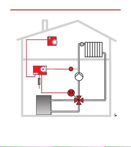
Hot Water Heating with Room Control
TW
ZG215N
////
ZG Control Unit
VM Servomotor
ZR Heating mixing valve
VF Flow sensor
VF
//
VM
////
TW Temperature selector
with room sensor
P Heating circuit pump
P
ZR
CBZG117.cdr
Page 3

Operation as a Heating Control
(Fig. left)
The remote control (TF) is composed of a temperature sensor
and atemperatureselector. (If desired also two separateddevices
can be used.)
The temperature sensor measures the actual room temperature.
n
The desired value for the room temperature is to be set on
n
the temperature selector.
On the basis of both of these values the control unit calculates the
necessary watertemperature (flow temperature).It is measured by
the flow sensor (VF). If the flow temperature differs from the set
value, the control unitadjusts themixing valve (ZR)with the ser
vomotor (VM) so that the right heat input is provided to the radi
ators.
Themixing valve determines the flow temperature by mixing the
hot water from the boiler with the colder return water.
Theheating circuit pump (P) provides for the circulation of the
hot water. It is not operated by the control unit.
Thetemperature selector (TF) is used as a remote control, e.g. if
the control unit is mounted in the cellar: by means of the selector
knob P2 the room temperature can be changed. With the party
switch S1 the night economy option can be suspended.
-
-
Page 4
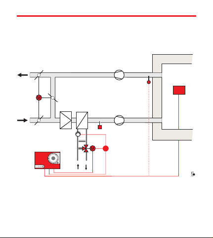
Air-handling system with mixing chamber
VM
ZG 215N
///
///
///
ZG Control Unit
VM Servomotor
ZR Heating mixing valve
LF
FT
Poti
LF Air duct sensor
TW Temperature selector
FT Frost protection thermo
//
TW
CB2283
-
Page 5
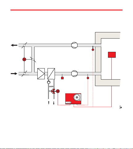
Air-handling system with heating coil
ZG Control Unit
VM Servomotor
ZR Heating mixing valve
LF
FT
LF
VM
ZG 215N
////////
LF Air duct sensor
TW Temperature selector
FT Frost protection thermo
//
TW
//
///
CB2286
-
Page 6

Operation as an Air-handling Control
(fig. left both
The operation of the air-handling control is basically the same as
for warm water heating. Instead of the flow temperature, the air
temperature in the supply duct is measured.
The control unit calculates the necessary heat demand and regula
tes the drivemotor sothatthe desired room temperature is reached.
Depending on the layout of the air-handling system, the drive mo
tor operates on a different part of the system:
In case of a mixing chamber system the blinds for the inco
n
ming and outgoing air are set.
In case of heating coil control the hot water temperature is
n
set for air heating.
In both oftypes ofsystem, the supply of heat isregulated so that the
room temperature setwith thetemperatureselector is maintained.
)
-
-
-
Page 7

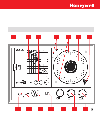
Operating and Display Components
Pos. Function Basic Setting
A
Proportional Range
B
Operating point setting
C Reduced Mode -8
P1 Sensitivity 5
S Operating mode selector auto
L1 “Hotter” LED (red)
L2 “Colder” LED (green)
1 Instructions compartment
2 Heating curve diagram
3 Basic Settings
4 Reserve trip pins
5 Inserted trip pins
6 Timer (optional)
7 Pointer for current time
Settings on the Temperature Selector
P2 Selector knob 0
S1 Party switch auto
4
50
Page 8
Operating mode selector
manu the controlunit is deactivated(the timer runs).The mixing
valve can be set manually (by hand). The pump is switched on.
auto Recommended setting for greater energysaving: automatic
change betweenday and reducedmode according to thetimer with
night switch-off.
Manual day mode, timer inactive.
Manual night mode according to the settings on the
setting knobs B minus C , the timer remains inactive.
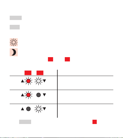
LED’s
L1 L2
In themanu settings ofthe operating mode selector S there is no
LED display.
Both LED’s light up:
“neutral”
– mixing valve stops
only red LED lights up:
“hotter”
– mixing valve opens
only green LED lights up:
“colder”
– mixing valve closes
Page 9

Putting into service
Set the timer 6 with the current time.
n
Set the operating mode selector S to auto .
n
The remaining basic factory settings are printed under 3 on the
control unit.
Timer for reduced mode 6
With theaid of thetimer, the roomtemperature during idleperiods
can be reduced automatically to save on operating costs.
The timer has a built-in power reserve of approx. 60 hours thanks
to a rechargeable battery.
Changing the program
Factory settings: red pin 6:00, blue pin 22:00.
Pull out the trip pin and insert it again at the desired
n
switch-on time. Push in the trip pins until they reach the stop.
Owing to the different lengths, the trip
pins must always be inserted in ared/blue
alternate order. Thered trip pin switches
on day mode, while the blue pin activates
reduced mode.
CB5044.7.cdr
Page 10

In order tomake surethat the rooms are heated well inthe morning,
the heating system’sday mode should be activated betweenhalf an
hour and an hour before using the rooms.
Energy saving tip: Reduced mode can be activated
up to an hour before the room is left. The storage
capacity of the heating system and building is
enough to keep the rooms warm for some time.
Timer with day program
The dayprogram is repeated every24 hours. Ifa (second) decrease
in temperature isdesired inthe course of the day to saveenergy, the
program needs tobe extended. Take the extra trippins 4 and insert
them at the desired time.
Example:
Desired time program
Normal temperature:
6:00 h to 8:00 h and 16:00 h to 22:00 h night decrease:
22:00 h to 6:00 h
day decrease: 8:00 h to 16:00 h
Position of the trip pins:
red pin 6:00 h – Start day mode (normal temperature)
blue pin 8:00 h – Start day decrease
red pin 16:00 h – Start day mode (normal temperature)
blue pin 22:00 h – Start night decrease
Page 11

Timer with week program
The timer has a changeable dial.
With the week program dialing a different heating program for
each weekday is possible.
The dial isprepared exfactory for the day program and,if required,
it can bechanged toweekprogram (see installation instructions).
Setting the right time
To set the time, the time dial is to be placed on the trip pins and
turned clockwise until the indication on the setting marker 7
matches with the current time.
Page 12

Optimization of the Settings
Basic Setting
(for hot water heating operating with temperature between
20 and 90 °C)
A è 4 B è 50 C è -8
During the regulation procedure open the radiator valves
n
completely. (Set the thermostat valves at the maximum va
lue).
If in the test room (room where the temperature sensor is
n
located) radiator valves are installed, these must be left
open always.
Close all windows and doors.
n
Proceed gradually by making only small changes.
n
Wait for the outcome of the change after each setting
n
(approx. 1 h).
Depending on the type of system – radiator/convector heating
(up to 90 °C), low temperature heating,air heating, mixing cham
ber regulation – and depending on the layout of the heating surfa
ces various flow or supply temperatures are needed to reach the
right room temperature – and hence also different settings on the
setting knobs.
-
-
-
Page 13

Proportional range: Setting knob
To makesure that thecontrol unit maintains the desired roomtem
perature, an operating range (regulation range) is to be given. The
operating rangedefines the relation betweenthe room temperature
and flow temperature or the setting of the regulating unit. Since
there is always a specific relation (proportion) between the room
and flow temperature in the operating range, it is also called
proportional rangeXp. For most 90/70 hotwater heating systems,
A è 4 is correct as the basic setting.
If with this setting (A è 4) aconstant room temperature is obtai
ned and the mixing valve position remains more or less the same
over a long period of time, no correction is necessary.
If, however, periodic room temperature oscillations occur, becau
se the mixing valve opens and closes intermittently, a larger pro
portional range is to be set (e. g. A è 5).
Description of the Operating Diagram
With the setting knob A the proportional range can be set. The
numeric value seton setting knob A means a proportionalrange in
% (or°C) for an operating rangeof the actuator of 0 to 100 %. The
smaller the numeric value on the setting knob A , the steeper the
operating characteristic curve of the regulation is. A steep opera
ting characteristic curve implies that already at a small room tem
perature oscillation a relatively intense heat convection to the
room occurs.
A
-
-
-
-
-
-
Page 14

With large numeric values on the setting knob A the operating
characteristic curve of the control unit is more level. For a small
deviation in the set room temperature, the supply of heat to the
room is hence changed only slightly and for fine dosing.
All the characteristic curves split in the operating pointto indicate
the rotation of the operating characteristic curve when turning the
setting knob A .The illustrated characteristiccurves A è 4 and
A è 9,5 correspond to the setting values 4 and 9.5 on the set
ting knob A . The operating point (settable with setting knob B )
is to be located for usual heating modes halfway between the lar
gest required and the least possible heating flow temperature.
Setting knob
A
Xp100in%2468101214161820
Xp 70 in °C 1.4 2.8 4.2 5.5 7.0 8.2 9.6 10.9 12.4 13.9
Xp 30 in °C 0.6 1.2 1.9 2.4 2.8 3.4 4.0 4.7 5.2 6.0
Xp 20 in °C 0.4 0.8 1.2 1.6 2.0 2.2 2.6 3.2 3.6 4.0
Setting of the operating point: Setting knob
With setting knob B the operating point of the operatingcharac
teristic point can be moved. The corresponding scale is planned in
“°C flow temperature” or “% valve position”. Basically, the
operating point is to be moved with setting knob B to the middle
of the system’s operating range. It is for example 45 °C for a hea
ting system in which the execution value matches the standard
2468101214161820
B
-
-
-
-
Page 15

design valueand which atthe lowest outdoortemperature requires
a maximum heating water temperature of approx. 70 °C and a mi
nimum temperatureof approx. 20 °C. Experience shows that most
systems are quite oversized. For the usual 70/50 radiator heating
systems, the basic setting B è 45 (instead of 50 °C) is correct.
Night decrease: Setting knob C
On setting knob C the size of the reduction to be triggered by the
timer isto be set. The settingof C gives a parallel shift ofthe ope
rating characteristic curve to the left (see dotted curve II). Thisle
ads toa decrease inthe room temperature.The scale divisionof C
corresponds toa room temperature decrease ofapprox. K (°C). “0”
means no decrease.
Example: C è -8 means that the nighttime room temperature
target valueis lower by 8 Kcompared to the daytime value,so that
the room temperature at night can decrease to approx. 8 K below
the set daytime temperature and hence
e. g. to 12 °C (20 °C −8 K = 12°C).
The recommendedsetting C at -8 makes it possibleto save quite a
lot of energywith a large nighttime decrease. In somebuildings the
rooms may become too cold.
In these cases, it is recommended to set a night decrease value of
about -5 or to switch on day mode earlier.
-
-
-
Page 16

Examples with other operating ranges:
1) Low temperature heating
n
maximum flow temperature 50 °C,
minimum flow temperature 20 °C,
average operating temperature (50 + 20):2=35°C;
The operating point of the operating characteristic curve is to
be set at 35 °C.
B è 35
A è 5
2) Ventilation and air conditioning systems:
n
maximum supply temperature 40 °C
minimum supply temperature 20 °C
average operating temperature (40 + 20):2=30°C
The operating point of the operating characteristic curve
is to be set at 30 °C.
B è 30
A è 10
3) Mixing chamber:
n
Valve setting AL 100 %, AL at
valve setting AL 0 %, AL to
B è 50
A è 8
( S1 è K, S2 è 1)
When using separated temperature sensors and target
value setting devices (TW 21...23), the function selector
on theback of the control unit S2 is tobe set always on
1 . Thesetarget valuesetting devicesare gaged in°C.
Page 17

Remote Control TF 22 (optional)
Setting the Room Temperature
On setting knob P2 the setting of the room temperature can be
fine-tuned. The normal settingis the room temperature set on con
trol unit(setting knob B ) (mainly 20°C to 22°C, the roomtempe
rature is not measured on the temperature selector). The scale on
the selector is divided from -7 to +7 and corresponds more or less
to the variation in degrees.
+ è Increasing the Room Temperature
– è Lowering the Room Temperature
The functioning of the selector knob P2 corresponds to the
functioning of the setting knob B on the control unit and gives a
parallel displacement of the heating curve along the oblique room
temperature axisindicated in thediagram. The valueson the selec
tor knob P2 and thesetting knob B are added on the controlunit:
S1
P2
-
-
-
Page 18

Examples B è 0 B è +1
Selector knob P2 -1 0 +1 +2 -1 0 +1 +2
Room temp. [°C] 19 20 21 22 20 21 22 23
If no temperature selector is available, the desired room tempera
ture can be set only on the setting knob B of the control unit.
Party switch S1
The temperature selector’sparty switchhasthe following settings:
auto automatic change to day mode or reduced mode
according to the timer
manual day mode, timer not active
manual night mode, timer not active
(the “night” duration mode is possible only if the
hours are set.)
If, for example, the heating is to stay open longer,
the Partyswitch is to be set on manual day mode.
Do not forget to switch back if the automatic mode is
to be activated again later on.
-
Page 19

Instructions for the Technician (only!)
Removing the Timer (see also the install. instructions)
Operating steps:
1. Pull out the instructions case.
n
2. Hold the timer by the two white stems and turn to the left
n
until the connector is released.
3. Remove the timer.
n
(To install the timer proceed in the opposite order.)
Regulation Stability (Sensitivity)
The stability of the regulation can be modified with the setting
potentiometer P1 .
For the regulation technician:
By means of P1 set the proportional range of the PD control
unit. Recommended basic setting: P1 è 10.
In case of unstable regulation, set higher values.
Setting potentiometer (for special cases)
Below the timer you will find the two potentiometers P6
n
and P8 (see fig.). After removing the timer these can be set
with a screwdriver. The factory basic setting is correct in
most cases and needs to be reset only in special cases and
only by a technician.
Page 20

Potentiomer P6 : Minimum limit
n
In case of air-hand
ling systems minimum
outside air rates or mini
mum flow temperatures
are necessary. P6 deter
mines the minimum ope
ning of the setting valves
between 0...70 %. For
heating systems mini
mum flow temperatures
of 0...70 °C can be set.
Factory basic setting: P6 è 0
Potentiometer P8 : Feedback balancing
n
In heating systemswithout flow sensor (e. g. quantityregulation in
the flow)or in air-handlingsystems, the controlunite works witha
potentiometer feedback of the servomotor. Changes in special
cases, ife. g. with valveactuation the motor’sswitch-off point and
the valve’s cut-off point do not match.
Factory basic setting: P8 è 0
Changes are to be made only by specialized personnel!
Make sure that:
1. Shifting towards + the closing angle increases
– the regulating unit is closed further
2. Shifting towards – increases the opening angle
– the regulating unit is opened further
-
-
-
-
-
P8 P6
Page 21

Function switch S1 / S2
( S1 and S2 are located on the back of
the controller insert. To move thefuncti
on switch insert, remove it as described
in the installation instructions.)
Function switch S1
n
"Heating – Cooling"
In air-conditioning systems, the control
ler can be used also to regulate the cooling load. The feedback of
the setting value (valve position) to the controller is provided by
means of a potentiometer in the servomotor, instead of the flow
sensor.
S1 è H (Heating) = factory basic setting
S1 è K (Cooling)
In setting K the following mean:
LED display red – colder (greater cooling load)
LED display green – hotter (less cooling load)
Function switch S2 "Target Value Definition"
n
S2 è 2 (target value in the pro. range, like setting knob B )
S2 è 1 (Operating point is always at the target value)
Position 1 of the switch is appropriate for example for mixing
chamber or greenhouse regulations. With this setting the entire
operating characteristic curve goes only in one direction.
Position the setting knob B always on 50.
= factory basic setting
-
S1 S2
-
Page 22

Troubleshooting Checklist
Is the heat generator at the required temperature?
n
è Read the heat generator’s thermometer.
Is the burner ready?
n
Is the burner failure lamp on?
è If necessary, press the suppressor.
Was the temperature selector set by mistake?
n
Setting of the selector knob P1
Check the setting on the control unit.
n
Setting knobs BCand operating mode selector S .
Is the timer running? Is the displayed time correct?
n
è Check the time and switch-on point.
If the problem still has not been solved after checkingthe settings,
position the setting knob B on +7
The servomotor should now open the mixing valve and the red
LED L2 should light up. If this is not the case, the control system
has failed. Contact your heating technician.
Page 23

Manual mode
In case of the breakdown of the
heating mode regulation you can
proceed temporarily as follows:
1. Set the operating mode se
n
lector S on manu .
2. Open the mixing valve by
n
hand until the desired flow
and room temperatures are
reached.
CB5043.7.cdr
– The coupling incorporated in the mixing valve drive unit
provides for the release of the connection between the
motor and the mixing valve.
– Press firmly on the unlock key on the cover of the drive
unit and keep the key pressed (firmly!).
– Use the setting lever to set the mixing valve in the desi
red
position.
After eliminating the problem the mixing valve is set
again to the right position by the control unit in au
tomatic mode.
-
-
-
Page 24

Reference
Installation instructions
Compact Control Units ZG 215N / 215 VN / 252 N
EN 1H-0181 GE51
Operating Instructions
ZG 252N: EN-2H0215 GE51
ZG 215N: EN-2H0216 GE51
ZG 215V: EN-2H0217 GE51
“Informationsschrift”(Planning broschure in German)
L3 – Komfort-Compact Regler
GE-0H 0327 GE51
Centra Regelungstechnik http://www.honeywell.de/hga
Honeywell AG
Böblinger Straße 17
D 71101 Schönaich
Telefon +49 (70 31) 637-01
Telefax +49 (70 31) 637-493
Technical data may be changed without prior notice.
EN 2H-0216 GE51 R1001 7157 559
 Loading...