

Page 1
Ê
Compact control units
ZG 215N / 215 VN / 252 N
MOUNTING INSTRUCTIONS
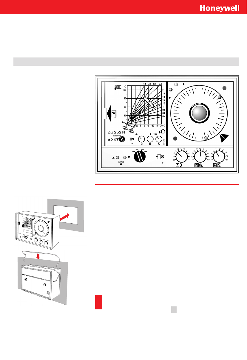
Mounting of the Control Unit
It can be mounted in any dry room, e. g. the boiler room. The device
can be mounted either in a cubicle door or on the wall.
Maximum permissible ambient temperature: 45 °C.
Ë
Door Mounting
Ê The casing cover isheldby a snap hinge closure.Press it inthe di
rection of the arrow on the left side and pull out.
Ë Insert the control unit in the dedicated door opening
(183 x 126 mm).
Ì Expand the retaining clips at the ends and insert in the relevant
holes. Fix into place the retaining clips by pressing down in the
fastening position.
Í Execute the electrical connection in the base (see the next page).
Then put on the base.
Important:
If the heating system is empty, the ZG 252N’s operating mode
selector is to be positioned on 2 . By doing so, the circulation
pump is deactivated and protected against dry-running.
-
Page 2
ÊË
ÌÍ
ÎÏ
Ð
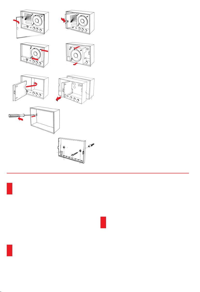
Wall mounting
Ê The casing cover is held by a snap hinge closure.
Press it in the direction of the arrow on the left
side and pull out.
Ë Hold the discharge compartment by the handle
and turn out to the right by exerting a light pres
sure. The instructions manual is kept here.
Ì Press the timer on bothpin inthe direction of the
arrow.
Í Pull out the timer.
Î Hang the slide of the instructions case in the
relevant recess of the insert.
Ï Pull the controller insert out of the casing with
the aid of the slide on the instructions case.
Ð Press the left lock pinto theleft witha screwdri
ver; by doing so, the case is freed from the devi
ce’s base.
Ñ Mount the device’s base with two 0.4 mm Æ
screws and dowels horizontally on the wall.
The assembly is to be carried out in the opposite
order.
-
-
-
Ñ
Electrical Connections
The electrical connections are to be carried
out by a technician!
Cross sections
n
Left terminal strip (base):
230 V AC 1.5 mm²
(connection to the control unit, servomotor,
pump)
n
Right terminal strip (base):
18 V DC >= 0.75 mm²
(connection to the sensors and selectors)
The 18 V lines are to be laid separately from
the 230 V lines. Use shielded cablesin the pre
sence of intense HF disturbance fields!
Wiring
The single accessory parts are to be connected ac
cording to the wiring diagram on the back of the ca
sing of this device model. When using the ZG 252N
in low temperature heating systems (e.g. floor hea
ting) an additional thermostat is recommended to
provide separate over-temperature limitation. With
230 V/50 Hz the servomotor and circulation pump
require the jumper from terminal 5 to 6.
The local regulations on earthing and
resetting are to be followed carefully
when connecting the device.
Earlier temperature selector and sensor versions
without additional letters A (e. g. TW 20, RF 20,
TF 20, etc.) have the same electrical connections
and the same resistance values as the device
-
versions with with additional letter A.
Noise suppression
Our control units are all provided with noise sup
pression.
-
-
-
Page 3

Checking the Control System
n
Before putting the system into service, check
whether the control device is connected as illu
strated in the wiring diagram.
n
The servomotor’s sense of rotation can be deter
mined by setting the control unit’s operating
mode selector on ”auto“ for ZG 252N or ”auto“
for ZG 215N / ZG 215VN and by changing the
room target value on setting knob B (ZG 252N)
or on the TW/TF (ZG 215N / ZG 215VN).
Setting knob B
or TW / TF
Turn towards + Red Opens
Turn towards – Green Closes
If the sense of rotation is wrong, invert termi
nals 10 and 11 on the left-hand of the terminal
strip.
Connecting the Potentiometer
If a potentiometer is used as feedback with the
ZG 215N instead of the flow sensor VF 20, also ter
minals 4 and 5 on the right-hand are to be inverted
besides terminals 10 / 11 if the sense of rotation of
the actuator (mixer, ventilation valves), is wrong.
When opening the actuator the resistance between
terminals 3 / 4 of the motor must belower, while the
resistance between terminals 4 / 5 of the motor
amounts always to 10 kW.
Pump Activation in the ZG 215N
If no heat input is required, thecirculation pumpcan
be switched off by means of an auxiliary switch in
the motor. The auxiliary switch makes sure that the
circulation pump is switched off when the mixer is
closed.
LED
Display
Servomotor
Checking the Temperature Sensors and
-
-Selectors
By measuring theresistance itcan bechecked whet
her the temperature sensors and selectors are con
nected correctly.
(The indicated terminal numbers refer to the mar
kings on the sensors and selectors.)
Temperature Sensor AF20, VF 20, VF 20A
Resistance values (R) at ambient temperature (t)
t [°C] -20 -10 0 +20 +25 +30 +70 +90
R[kW] 220 122 70 25 20 16 3,1 1,5
Temperature Selector TW 20A, TF 20A
Setting on the Selector Resistance [kW]
-
Right stop (+12) 147 100 47
Left stop (-12) 100 147 47
between the terminals
1/2 1/3 2/3
Temperature Selectors TF 22 and TFU 22
-
Setting on the selector Resistance [kW]
Right stop (+7) 28.7 4,8 0
Left stop (-7) 69.8 13.8 0
between terminals1/ 3
auto day night
Temperature Selectors TW 21A...TW 23A
Setting on the Selector Resistance [kW]
between the terminals
1/2 1/3 2/3
TW 21A (-15.. . +15°C)
TW 22A (0...+30 °C) 58 68 10
TW 23A (20..+70 °C) 26 27 9
35 45 10
-
-
-
TW 21A toTW 23A canbe connected only tothe
controllers ZG 215N / ZG 215VN.
Party switch
Resistance between terminals2/4onTW20Aor
TF 20:
Switch position ”Automatic“: ¥ (infinite)
Switch position ”Day mode“:0kW
Page 4

Terminal diagrams
230 V~ SELV
123456789
PE
ALTERNATIVE ALTERNATIVE
567 9
123
TW 21
TW 22
TW 23
10 11 12
123
12
123456789
VF1 PotiNL
ALTERNATIVE
RF 20
VF 20
LF 20
ZG 215 N
10 11 12
ext.
123456
TF 22
7 9 12 10
123456
U+
TFU 22
Protection against the
destruction of the com
ponents owing to elec
trostatic discharges:
These are to be discharged to an
earthed line (e.g.water line)befo
re they touch the components on
the controller board!
Attention! Before acces
sing the connection ter
CB50227F
minals, all the mains
supply circuits are to be
switched off.
-
-
-
-
-
230 V~ SELV
123456789
10 11 12
123
ALTERNATIVE ALTERNATIVE
5678
1234
TW 20
Centra Regelungstechnik
Honeywell AG
Böblinger Straße 17
D 71101 Schönaich
Telefon +49 (70 31) 637-01
Telefax +49 (70 31) 637-493
ZG 252 N
123456789
VF
AFNLPE
123456
TF 22
71210
123456
U+
TFU 22
10 11 12
ext.
ZG 252 N
7
...12
10 9
Hometronic
HCE 60
712
54
Hometronic
HCM 200
In case of fixed installa
tion an all-pole discon
nection device with at
leasta3mmcontact
opening is to be instal
led.
Reference
Operating instructions
ZG 252NV EN-2H0215 GE51
ZG 215NV EN-2H0216 GE51
ZG 215VN EN-2H0217 GE51
“Informationsschrift”
(Planning broschure in German)
L3 – Comfort-Kompakt-Regler
GE-0H 0327 GE51
[CBZG_MAE.VP]
CB50247F
-
-
-
EN 1H-0181 GE51 R1001 07157 562 http://www.honeywell.de/hga
 Loading...