

Page 1

YJ-HF500
Area-Imaging Scanner
User’s Guide
Page 2

Disclaimer
Honeywell International Inc. (“HII”) reserves the right to make changes in specifications and other information contained in this
document without prior notice, and the reader should in all cases consult HII to determine whether any such changes have been
made. The information in this publication does not represent a commitment on the part of HII.
HII shall not be liable for technical or editorial errors or omissions contained herein; nor for incidental or consequential damages
resulting from the furnishing, performance, or use of this material. HII disclaims all responsibility for the selection and use of
software and/or hardware to achieve intended results.
This document contains proprietary information that is protected by copyright. All rights are reserved. No part of this document
may be photocopied, reproduced, or translated into another language without the prior written consent of HII.
Copyright 2016 Honeywell International Inc. All rights reserved.
Web Address:
Other product names or marks mentioned in this document may be trademarks or registered trademarks of other companies
and are the property of their respective owners.
www.honeywellaidc.com
Page 3

Table of Contents
Customer Support
Technical Assistance ...........................................................................................................vii
Product Service and Repair ................................................................................................. vii
Limited Warranty .................................................................................................................. vii
Send Feedback .................................................................................................................... vii
Chapter 1 - Getting Started
About This Manual ...............................................................................................................1-1
Unpacking Your Device .......................................................................................................1-1
Connecting the Device.........................................................................................................1-1
Connecting with USB .....................................................................................................1-1
Connecting with RS232 Serial Port................................................................................1-2
Reading Techniques ............................................................................................................1-3
Menu Bar Code Security Settings........................................................................................1-3
Setting Custom Defaults ......................................................................................................1-3
Resetting the Custom Defaults ............................................................................................1-4
Chapter 2 - Programming the Interface
Introduction ..........................................................................................................................2-1
Programming the Interface - Plug and Play .........................................................................2-1
RS232 Serial Port ................................................................................................................2-1
USB IBM SurePos ...............................................................................................................2-1
USB PC or Macintosh Keyboard..........................................................................................2-2
USB HID ..............................................................................................................................2-2
USB Serial ...........................................................................................................................2-2
ACK/NAK Mode .............................................................................................................2-2
Verifone
Gilbarco
Bioptic Aux Port Configuration .............................................................................................2-3
Datalogic™ Magellan
NCR Bioptic Aux Port Configuration ....................................................................................2-4
Wincor Nixdorf Terminal Default Settings ............................................................................2-4
Wincor Nixdorf Beetle™ Terminal Default Settings .............................................................2-4
Wincor Nixdorf RS232 Mode A ............................................................................................2-5
Keyboard Country Layout ....................................................................................................2-5
Keyboard Style...................................................................................................................2-13
Keyboard Conversion ........................................................................................................2-14
Control Character Output...................................................................................................2-14
Keyboard Modifiers ............................................................................................................2-14
®
Ruby Terminal Default Settings...........................................................................2-3
®
Terminal Default Settings ....................................................................................2-3
©
Bioptic Aux Port Configuration........................................................2-3
i
Page 4

RS232 Modifiers ................................................................................................................ 2-16
RS232 Baud Rate........................................................................................................ 2-16
RS232 Word Length: Data Bits, Stop Bits, and Parity .................................................2-17
RS232 Receiver Time-Out...........................................................................................2-18
RS232 Handshaking....................................................................................................2-18
RS232 Timeout............................................................................................................ 2-19
XON/XOFF ..................................................................................................................2-19
ACK/NAK..................................................................................................................... 2-19
Scanner to Bioptic Communication ................................................................................... 2-20
Scanner-Bioptic Packet Mode .....................................................................................2-20
Scanner-Bioptic ACK/NAK Mode.................................................................................2-20
Scanner-Bioptic ACK/NAK Timeout.............................................................................2-20
Chapter 3 - Input/Output Settings
Power Up Beeper ................................................................................................................3-1
Beep on BEL Character....................................................................................................... 3-1
Good Read and Error Indicators..........................................................................................3-1
Beeper – Good Read.....................................................................................................3-1
Beeper Volume – Good Read........................................................................................3-2
Beeper Pitch – Good Read............................................................................................ 3-2
Beeper Pitch – Error ......................................................................................................3-2
Beeper Duration – Good Read ......................................................................................3-3
LED – Good Read .........................................................................................................3-3
Number of Beeps – Good Read ....................................................................................3-3
Number of Beeps – Error............................................................................................... 3-3
Good Read Delay ..........................................................................................................3-4
User-Specified Good Read Delay..................................................................................3-4
Presentation Mode ..............................................................................................................3-4
LED Illumination.............................................................................................................3-4
Idle Illumination - Presentation Mode ............................................................................ 3-5
Presentation Sensitivity .................................................................................................3-5
Presentation Centering.................................................................................................. 3-6
Poor Quality Codes ............................................................................................................. 3-7
Poor Quality PDF Codes ...............................................................................................3-7
Mobile Phone Read Mode ................................................................................................... 3-7
Reread Delay.......................................................................................................................3-8
User-Specified Reread Delay ..............................................................................................3-8
2D Reread Delay ...........................................................................................................3-8
Character Activation Mode .................................................................................................. 3-9
Activation Character ......................................................................................................3-9
End Character Activation After Good Read................................................................... 3-9
Character Activation Laser Timeout ............................................................................ 3-10
Character Deactivation Mode ............................................................................................3-10
Deactivation Character ................................................................................................3-10
Illumination Lights..............................................................................................................3-10
Aimer Mode ....................................................................................................................... 3-11
Centering ........................................................................................................................... 3-11
Video Reverse ...................................................................................................................3-12
ii
Page 5

Working Orientation........................................................................................................... 3-13
Chapter 4 - Data Editing
Prefix/Suffix Overview ......................................................................................................... 4-1
To Add a Prefix or Suffix:............................................................................................... 4-1
To Clear One or All Prefixes or Suffixes........................................................................ 4-2
To Add a Carriage Return Suffix to All Symbologies..................................................... 4-2
Prefix Selections..................................................................................................................4-2
Suffix Selections .................................................................................................................. 4-2
Function Code Transmit ...................................................................................................... 4-3
Intercharacter, Interfunction, and Intermessage Delays...................................................... 4-3
Intercharacter Delay ......................................................................................................4-3
User Specified Intercharacter Delay.............................................................................. 4-3
Interfunction Delay.........................................................................................................4-4
Intermessage Delay....................................................................................................... 4-4
Chapter 5 - Data Formatting
Data Format Editor Introduction .......................................................................................... 5-1
Add a Data Format .............................................................................................................. 5-1
Other Programming Selections......................................................................................5-2
Terminal ID Table ................................................................................................................ 5-3
Data Format Editor Commands...........................................................................................5-3
Move Commands...........................................................................................................5-4
Search Commands........................................................................................................ 5-5
Miscellaneous Commands.............................................................................................5-6
Data Formatter ....................................................................................................................5-8
Primary/Alternate Data Formats .......................................................................................... 5-9
Chapter 6 - Symbologies
All Symbologies ................................................................................................................... 6-1
Message Length Description ............................................................................................... 6-1
Codabar...............................................................................................................................6-2
Codabar Concatenation................................................................................................. 6-3
Code 39 ............................................................................................................................... 6-4
Code 32 Pharmaceutical (PARAF)................................................................................ 6-5
Full ASCII....................................................................................................................... 6-6
Code 39 Code Page ......................................................................................................6-6
Interleaved 2 of 5.................................................................................................................6-7
NEC 2 of 5 ........................................................................................................................... 6-8
Code 93 ............................................................................................................................... 6-9
Code 93 Code Page ....................................................................................................6-10
Straight 2 of 5 Industrial (three-bar start/stop)...................................................................6-11
Straight 2 of 5 IATA (two-bar start/stop) ............................................................................ 6-12
Matrix 2 of 5.......................................................................................................................6-13
Code 11 ............................................................................................................................. 6-14
iii
Page 6

Code 128 ........................................................................................................................... 6-15
ISBT 128 Concatenation..............................................................................................6-15
Code 128 Code Page ..................................................................................................6-16
GS1-128 ............................................................................................................................ 6-17
UPC-A ............................................................................................................................... 6-17
UPC-A/EAN-13 with Extended Coupon Code ................................................................... 6-19
Coupon GS1 DataBar Output............................................................................................ 6-20
UPC-E0 ............................................................................................................................. 6-20
UPC-E1 ............................................................................................................................. 6-22
EAN/JAN-13 ......................................................................................................................6-23
Convert UPC-A to EAN-13 ..........................................................................................6-23
ISBN Translate ............................................................................................................6-25
EAN/JAN-8 ........................................................................................................................ 6-25
MSI ....................................................................................................................................6-27
GS1 DataBar Omnidirectional ........................................................................................... 6-29
GS1 DataBar Limited......................................................................................................... 6-29
GS1 DataBar Expanded .................................................................................................... 6-30
Codablock A ...................................................................................................................... 6-30
Codablock F ...................................................................................................................... 6-31
PDF417 ............................................................................................................................. 6-32
MacroPDF417 ................................................................................................................... 6-32
MicroPDF417.....................................................................................................................6-33
GS1 Composite Codes...................................................................................................... 6-33
UPC/EAN Version........................................................................................................6-34
GS1 Emulation .................................................................................................................. 6-34
TCIF Linked Code 39 (TLC39) .......................................................................................... 6-35
QR Code............................................................................................................................ 6-35
QR Code Page ............................................................................................................6-36
Data Matrix ........................................................................................................................ 6-37
Data Matrix Code Page ...............................................................................................6-37
MaxiCode .......................................................................................................................... 6-38
Aztec Code ........................................................................................................................ 6-39
Aztec Code Page.........................................................................................................6-39
Chinese Sensible (Han Xin) Code..................................................................................... 6-40
Postal Codes - 2D ............................................................................................................. 6-41
Single 2D Postal Codes:..............................................................................................6-41
Combination 2D Postal Codes:....................................................................................6-42
Postal Codes - Linear ........................................................................................................ 6-45
China Post (Hong Kong 2 of 5).................................................................................... 6-45
Korea Post................................................................................................................... 6-46
Chapter 7 - Utilities
To Add a Test Code I.D. Prefix to All Symbologies .............................................................7-1
Show Decoder Revision ...................................................................................................... 7-1
Show Scan Driver Revision ................................................................................................. 7-1
Show Software Revision...................................................................................................... 7-1
Show Data Format............................................................................................................... 7-1
Test Menu............................................................................................................................7-2
iv
Page 7

EZConfig-Scanning Introduction..........................................................................................7-2
Installing EZConfig-Scanning from the Web.................................................................. 7-2
Resetting the Factory Defaults ............................................................................................ 7-3
Chapter 8 - Serial Programming Commands
Conventions.........................................................................................................................8-1
Menu Command Syntax ...................................................................................................... 8-1
Query Commands ............................................................................................................... 8-1
Responses.....................................................................................................................8-2
Resetting the Custom Defaults............................................................................................ 8-3
Menu Commands ................................................................................................................8-3
Chapter 9 - Product Specifications
YJ-HF500 Scanner Product Specifications ......................................................................... 9-1
Standard Cable Pinouts.......................................................................................................9-2
Serial Output.................................................................................................................. 9-2
USB ...............................................................................................................................9-2
Chapter 10 - Maintenance and Troubleshooting
Repairs ..............................................................................................................................10-1
Maintenance ...................................................................................................................... 10-1
Cleaning the Device.....................................................................................................10-1
Inspecting Cords and Connectors ............................................................................... 10-1
Replacing Cable in the Scanner ........................................................................................ 10-1
Troubleshooting the Scanner ............................................................................................ 10-1
Appendix A - Reference Charts
Symbology Charts ...............................................................................................................A-1
Linear Symbologies .......................................................................................................A-1
2D Symbologies.............................................................................................................A-2
Postal Symbologies .......................................................................................................A-2
ASCII Conversion Chart (Code Page 1252)........................................................................A-3
Lower ASCII Reference Table.............................................................................................A-4
ISO 2022/ISO 646 Character Replacements ......................................................................A-7
Unicode Key Maps ..............................................................................................................A-9
Sample Symbols
Programming Chart
v
Page 8

vi
Page 9

Customer Support
Technical Assistance
To search our knowledge base for a solution or to log in to the Technical Support portal and report a problem, go to
www.hsmcontactsupport.com.
For our latest contact information, see www.honeywellaidc.com/locations.
Product Service and Repair
Honeywell International Inc. provides service for all of its products through service centers throughout the world. To find
your service center, go to www.honeywellaidc.com and select Support. Contact your service enter to obtain a Return
Material Authorization number (RMA #) before you return the product.
To obtain warranty or non-warranty service, return your product to Honeywell (postage paid) with a copy of the dated purchase record.
Limited Warranty
For warranty information, go to www.honeywellaidc.com and click Resources>Warranty.
Send Feedback
Your feedback is crucial to the continual improvement of our documentation. To provide feedback about this manual, contact the Honeywell Technical Communications department at ACSHSMTechnicalCommunications@honeywell.com.
vii
Page 10

viii
Page 11
1
YJ-HF500 USB
Connection:
Getting Started
About This Manual
This User’s Guide provides installation and programming instructions for the Honeywell HF500 corded area-imaging scanners.
Product specifications, dimensions, warranty, and customer support information are also included.
Honeywell bar code scanners are factory programmed for the most common terminal and communications settings. If you need
to change these settings, programming is accomplished by scanning the bar codes in this guide.
An asterisk (*) next to an option indicates the default setting.
Unpacking Your Device
After you open the shipping carton containing the product, take the following steps:
• Check for damage during shipment. Report damage immediately to the carrier who delivered the carton.
• Make sure the items in the carton match your order.
• Save the shipping container for later storage or shipping.
Connecting the Device
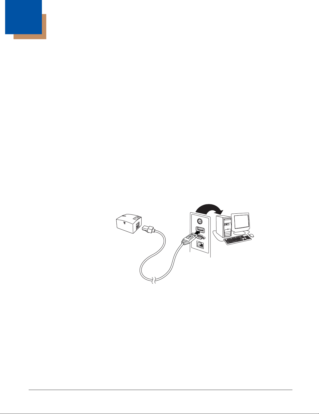
Connecting with USB
A scanner can be connected to the USB port of a computer.
1. Connect the appropriate interface cable to the device first, then to the computer.
Note: The power supply must be ordered separately, if needed.
2. The scanner beeps.
3. Verify the scanner operation by scanning a bar code from the Sample Symbols in the back of this manual.
The unit defaults to a USB PC Keyboard. Refer to page 2-2 for other USB terminal settings.
1 - 1
Page 12
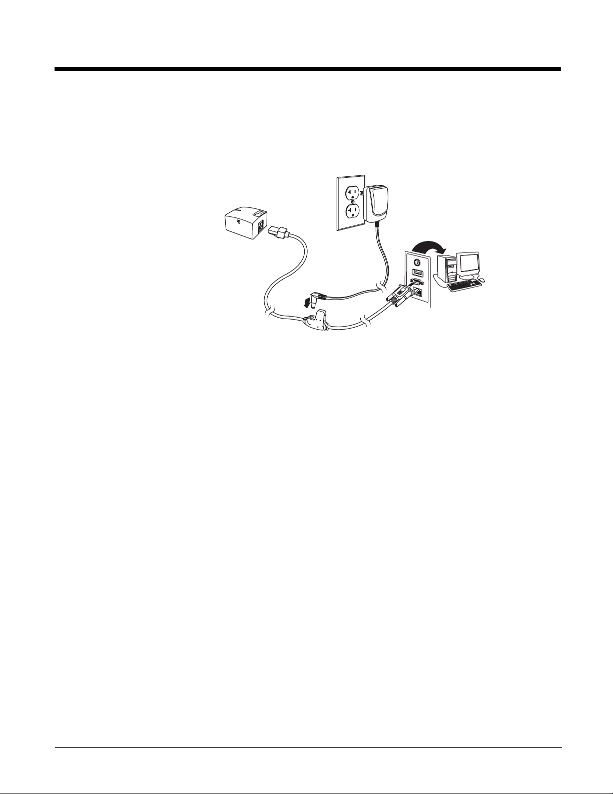
Connecting with RS232 Serial Port
YJ-HF500
RS232 Serial Port Connection:
1. Turn off power to the terminal/computer.
2. Connect the appropriate interface cable to the device.
Note: For the scanner to work properly, you must have the correct cable for your type of terminal/computer.
Note: The power supply must be ordered separately, if needed.
3. Plug the serial connector into the serial port on your computer. Tighten the two screws to secure the connector to the
port.
4. Once the scanner has been fully connected, power up the computer.
This interface programs 115,200 baud, 8 data bits, no parity, and 1 stop bit.
1 - 2
Page 13

Reading Techniques
Linear bar code
2D Matrix symbol
Set Custom Defaults
Save Custom Defaults
The scanner has a view finder that projects a bright red aiming beam that corresponds to the scanner’s horizontal field of view.
The aiming beam should be centered over the bar code, but it can be positioned in any direction for a good read.
The aiming beam or pattern is smaller when the scanner is closer to the code and larger when it is farther from the code. Symbologies with smaller bars or elements (mil size) should be read closer to the unit. Symbologies with larger bars or elements
(mil size) should be read farther from the unit. To read single or multiple symbols (on a page or on an object), hold the scanner
at an appropriate distance from the target and center the aiming beam or pattern on the symbol. If the code being scanned is
highly reflective (e.g., laminated), it may be necessary to tilt the code up 15° to 18° to prevent unwanted reflection.
Menu Bar Code Security Settings
Honeywell scanners are programmed by scanning menu bar codes or by sending serial commands to the scanner. If you want
to restrict the ability to scan menu codes, you can use the Menu Bar Code Security settings. Please contact the nearest technical support office (see Technical Assistance on page -vii) for further information.
Setting Custom Defaults
You have the ability to create a set of menu commands as your own, custom defaults. To do so, scan the Set Custom Defaults
bar code below before scanning the menu commands for your custom defaults. If a menu command requires scanning numeric
codes from the back cover, then a Save code, that entire sequence will be saved to your custom defaults. When you have
entered all the commands you want to save for your custom defaults, scan the Save Custom Defaults bar code.
1 - 3
Page 14

You may have a series of custom settings and want to correct a single setting. To do so, just scan the new setting to overwrite
Activate Custom Defaults
the old one. For example, if you had previously saved the setting for Beeper Volume at Low to your custom defaults, and decide
you want the beeper volume set to High, just scan the Set Custom Defaults bar code, then scan the Beeper Volume High
menu code, and then Save Custom Defaults. The rest of the custom defaults will remain, but the beeper volume setting will be
updated.
Resetting the Custom Defaults
If you want the custom default settings restored to your scanner, scan the Activate Custom Defaults bar code below. This is
the recommended default bar code for most users. It resets the scanner to the custom default settings. If there are no custom
defaults, it will reset the scanner to the factory default settings. Any settings that have not been specified through the custom
defaults will be defaulted to the factory default settings.
1 - 4
Page 15
2
RS232 Interface
USB IBM SurePos
(USB Handheld Scanner)
Interface
USB IBM SurePos
(USB Tabletop Scanner)
Interface
Programming the Interface
Introduction
This chapter describes how to program your system for the desired interface.
Programming the Interface - Plug and Play
Plug and Play bar codes provide instant scanner set up for commonly used interfaces.
Note: After you scan one of the codes, power cycle the host terminal to have the interface in effect.
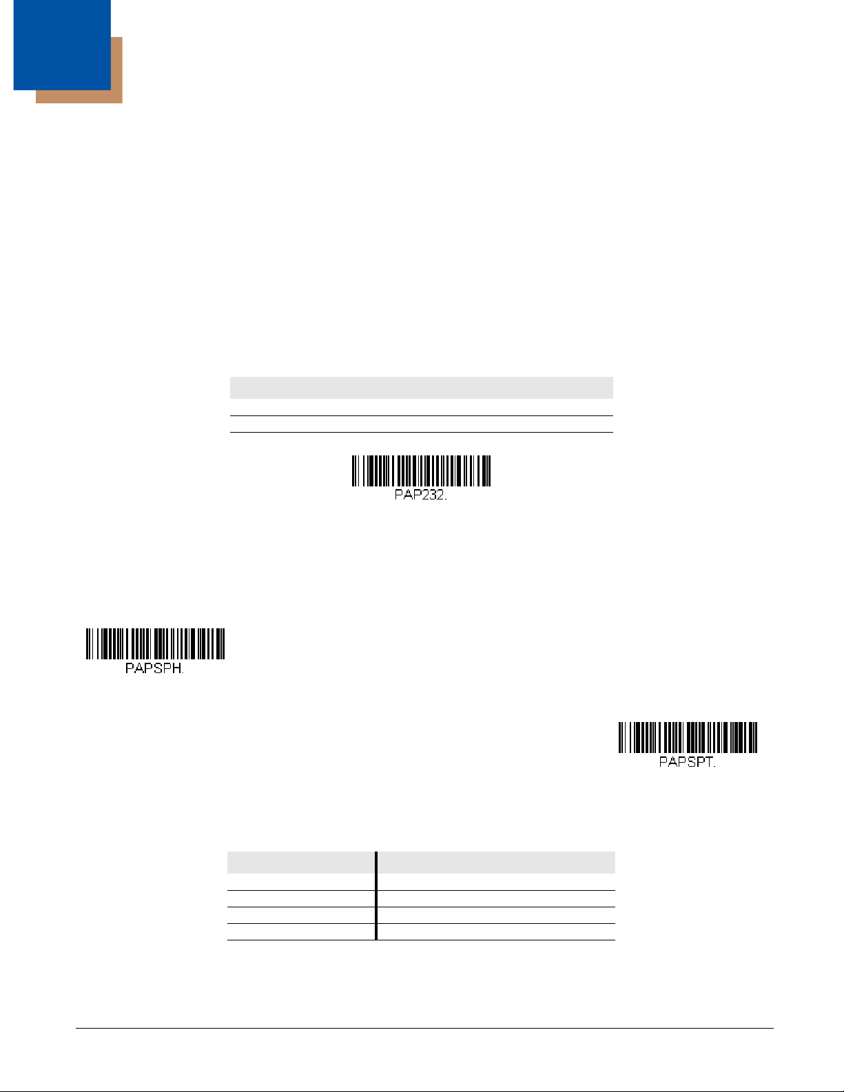
RS232 Serial Port
The RS232 Interface bar code is used when connecting to the serial port of a PC or terminal. The following RS232 Interface
bar code also programs a carriage return (CR) and a line feed (LF) suffix, baud rate, and data format as indicated below.
Option Setting
Baud Rate 115,200 bps
Data Format 8 data bits, no parity bit, 1 stop bit
USB IBM SurePos
Scan one of the following “Plug and Play” codes to program the scanner for an IBM SurePos (USB handheld scanner) or IBM
SurePos (USB tabletop scanner) interface.
Note: After scanning one of these codes, you must power cycle the cash register.
Each bar code above also programs the following suffixes for each symbology:
Symbology Suffix Symbology Suffix
EAN 8 0C Code 39 00 0A 0B
EAN 13 16 Interleaved 2 of 5 00 0D 0B
UPC A 0D Code 128 00 18 0B
UPC E 0A Code 39 00 0A 0B
2 - 1
Page 16
USB PC or Macintosh Keyboard
U
S
B
K
e
y
b
o
a
r
d
(
P
C
)
USB Keyboard (Mac)
USB Japanese Keyboard (PC)
USB HID Bar Code Scanner
USB Serial
ACK/NAK Mode On
* ACK/NAK Mode Off
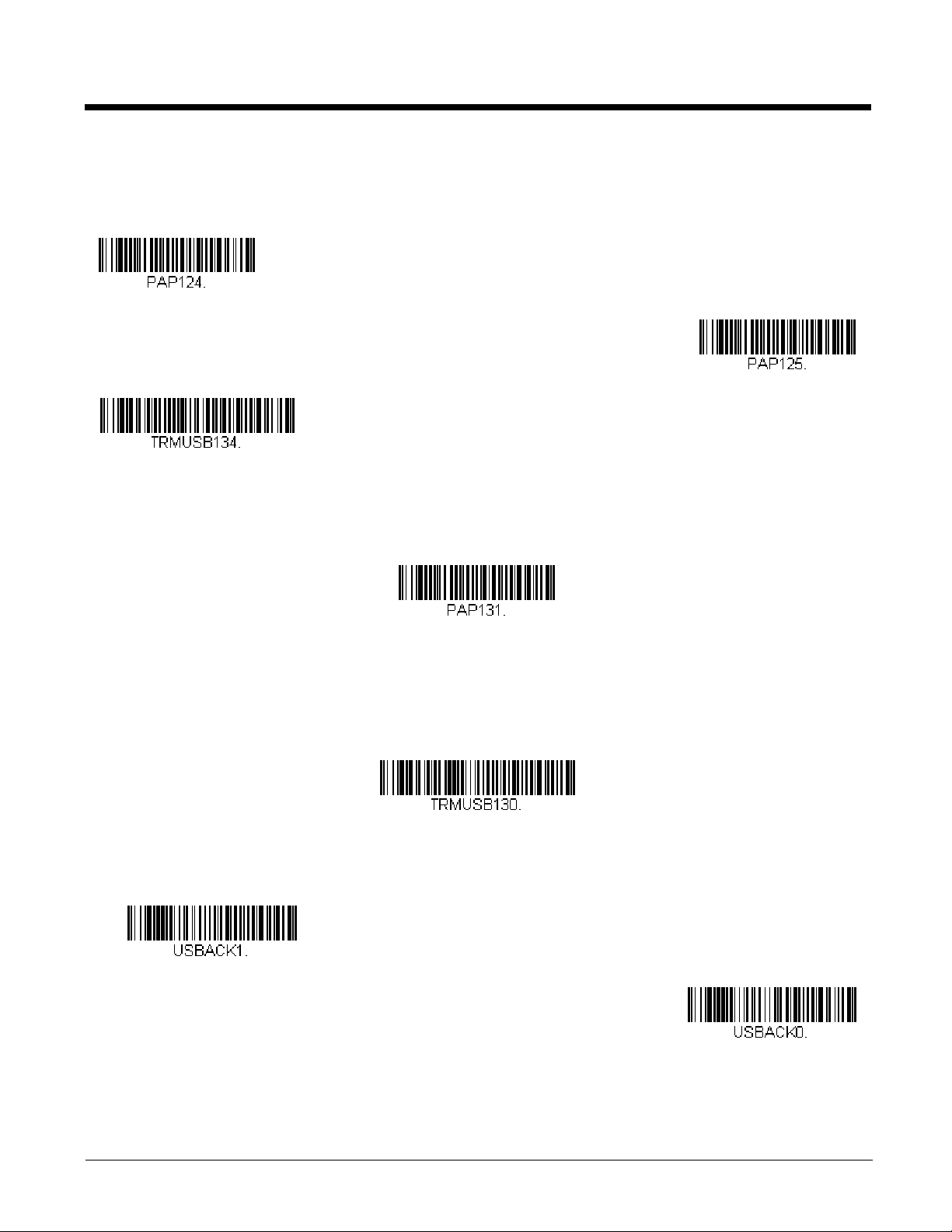
Scan one of the following codes to program the scanner for USB PC Keyboard or USB Macintosh Keyboard. Scanning these
codes also adds a CR and LF.
USB HID
Scan the following code to program the scanner for USB HID bar code scanners.
USB Serial
Scan the following code to program the scanner to emulate a regular RS232-based COM Port. If you are using a Microsoft®
Windows® PC, you will need to download a driver from the Honeywell website (www.honeywellaidc.com). The driver will use
the next available COM Port number. Apple® Macintosh computers recognize the scanner as a USB CDC class device and
automatically uses a class driver.
Note: No extra configuration (e.g., baud rate) is necessary.
ACK/NAK Mode
2 - 2
Page 17

Verifone® Ruby Terminal Default Settings
Verifone Ruby Settings
Gilbarco Settings
Honeywell Bioptic Settings
Datalogic Magellan Bioptic Settings
Scan the following Plug and Play code to program the scanner for a Verifone Ruby terminal. This bar code sets the baud rate to
1200 bps and the data format to 8 data bits, mark parity bit, 1 stop bit. It also adds a line feed (LF) suffix and programs the following prefixes for each symbology:
Symbology Prefix
UPC-A A
UPC-E A
EAN-8 FF
EAN-13 F
Gilbarco® Terminal Default Settings
Scan the following Plug and Play code to program the scanner for a Gilbarco terminal. This bar code sets the baud rate to 2400
bps and the data format to 7 data bits, even parity, 2 stop bits. It also adds a carriage return (CR) suffix and programs the following prefixes for each symbology:
Symbology Prefix
UPC-A A
UPC-E E0
EAN-8 FF
EAN-13 F
Bioptic Aux Port Configuration
Scan the following Plug and Play code to program the scanner for a Honeywell bioptic scanner auxiliary port configuration. This
bar code sets the baud rate to 38400 bps and the data format to 8 data bits, no parity, 1 stop bit.
Datalogic™ Magellan© Bioptic Aux Port Configuration
Scan the following Plug and Play code to program the scanner for a Datalogic Magellan bioptic scanner auxiliary port configuration. This bar code sets the baud rate to 9600 bps and the data format to 8 data bits, no parity, 1 stop bit.
2 - 3
Page 18
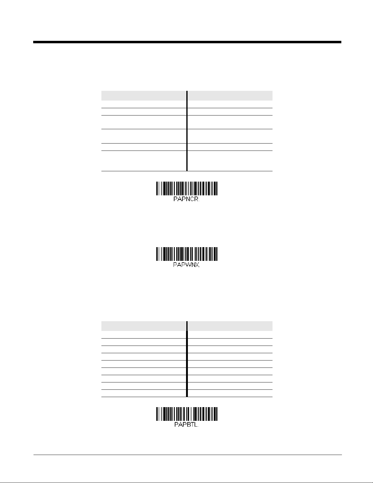
NCR Bioptic Aux Port Configuration
NCR Bioptic Settings
Wincor Nixdorf Terminal Settings
Wincor Nixdorf Beetle Settings
Scan the following Plug and Play code to program the scanner for an NCR bioptic scanner auxiliary port configuration. The following prefixes are programmed for each symbology:
Symbology Prefix Symbology Prefix
UPC-A A Interleaved 2 of 5 b
UPC-E E0 Code 128 f
GS1 DataBar
Omnidirectional
EAN-8 FF GS1 DataBar
Expanded
EAN-13 F Codabar N
Code 39 a Code 32
Pharmaceutical
(PARAF)
r
r
a
Wincor Nixdorf Terminal Default Settings
Scan the following Plug and Play code to program the scanner for a Wincor Nixdorf terminal. This bar code sets the baud rate
to 9600 bps and the data format to 8 data bits, no parity, 1 stop bit.
Wincor Nixdorf Beetle™ Terminal Default Settings
Scan the following Plug and Play code to program the scanner for a Wincor Nixdorf Beetle terminal. This bar code sets the
baud rate to 115200 bps and the data format to 8 data bits, no parity, 1 stop bit. The following prefixes are programmed for each
symbology:
Symbology Prefix Symbology Prefix
Aztec Code V Interleaved 2 of 5 I
Codabar N MaxiCode T
Code 93 L MicroPDF417 S
Code 128 K PDF417 Q
Data Matrix R QR Code U
EAN-8 B Straight 2 of 5 IATA H
EAN-13 A UPC-A A0
GS1 DataBar E UPC-E C
GS1-128 P All other bar codes M
2 - 4
Page 19
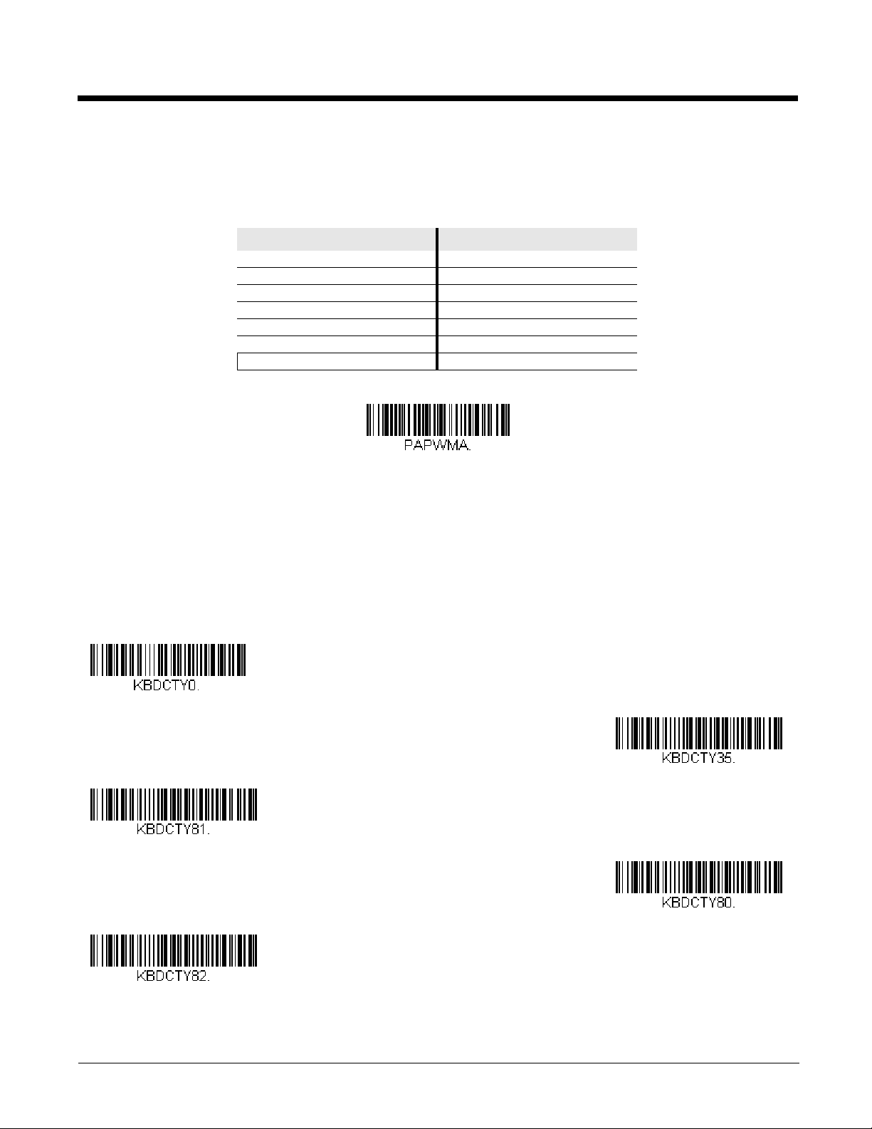
Wincor Nixdorf RS232 Mode A
Wincor Nixdorf RS232 Mode A
Settings
* United States
Albania
Azeri (Cyrillic)
Azeri (Latin)
Belarus
Scan the following Plug and Play code to program the scanner for a Wincor Nixdorf RS232 Mode A terminal. This bar code sets
the baud rate to 9600 bps and the data format to 8 data bits, odd parity, 1 stop bit. The following prefixes are programmed for
each symbology:
Symbology Prefix Symbology Prefix
Code 128 K EAN-13 A
Code 93 L GS1-128 K
Codabar N Interleaved 2 of 5 I
UPC-A A0 Plessey O
UPC-E C Straight 2 of 5 IATA H
EAN-8 B GS1 DataBar E
All other bar codes M
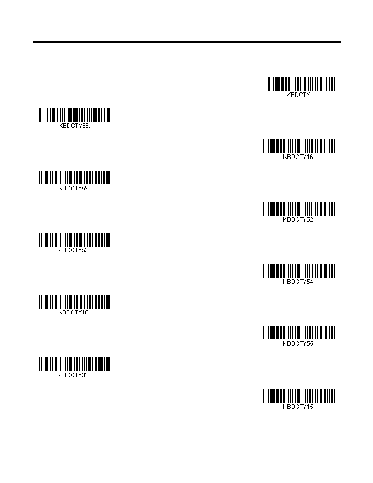
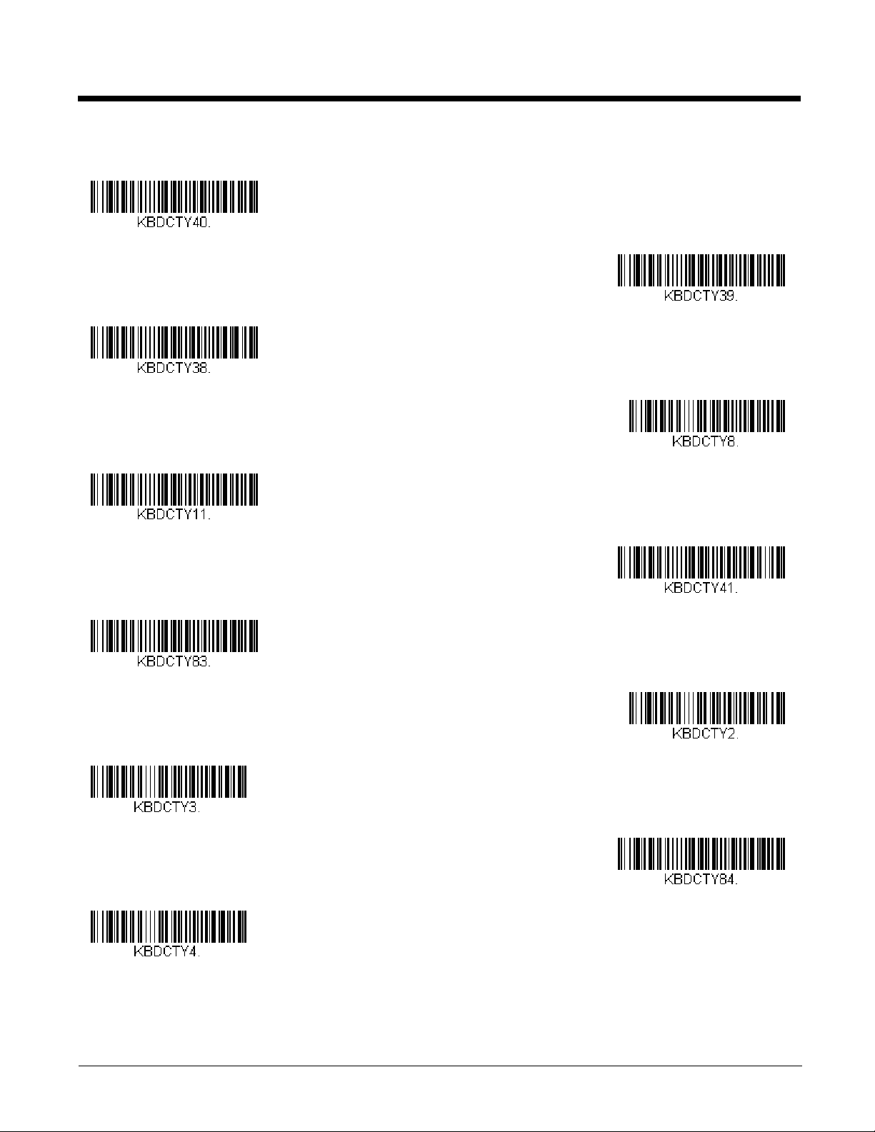
Keyboard Country Layout
If your interface is USB Keyboard, your keyboard layout default is a US keyboard. To change this layout, refer to the chart below
for your keyboard country. Scan the appropriate bar code below to change the layout.
By default, national character replacements are used for the following characters: #$@[\]^‘{|}~ See ISO 2022/ISO 646
Character Replacements on page A-7 to view the character replacements for each country.
Keyboard Countries
2 - 5
Page 20
Keyboard Countries (Continued)
Belgium
Bosnia
Brazil
Brazil (MS)
Bulgaria (Cyrillic)
Bulgaria (Latin)
Canada (French legacy)
Canada (French)
Canada (Multilingual)
Croatia
Czech
2 - 6
Page 21
Keyboard Countries (Continued)
Czech (Programmers)
Czech (QWERTY)
Czech (QWERTZ)
Denmark
Dutch (Netherlands)
Estonia
Faroese
Finland
France
Gaelic
Germany
2 - 7
Page 22
Keyboard Countries (Continued)
Greek
Greek (220 Latin)
Greek (220)
Greek (319 Latin)
Greek (319)
Greek (Latin)
Greek (MS)
Greek (Polytonic)
Hebrew
Hungarian (101 key)
Hungary
2 - 8
Page 23
Keyboard Countries (Continued)
Iceland
Irish
Italian (142)
Italy
Japan ASCII
Kazakh
Kyrgyz (Cyrillic)
Latin America
Latvia
Latvia (QWERTY)
Lithuania
2 - 9
Page 24
Keyboard Countries (Continued)
Lithuania (IBM)
Macedonia
Malta
Mongolian (Cyrillic)
Norway
Poland
Polish (214)
Polish (Programmers)
Portugal
Romania
Russia
2 - 10
Page 25
Keyboard Countries (Continued)
Russian (MS)
Russian (Typewriter)
SCS
Serbia (Cyrillic)
Serbia (Latin)
Slovakia
Slovakia (QWERTY)
Slovakia (QWERTZ)
Slovenia
Spain
Spanish variation
2 - 11
Page 26
Keyboard Countries (Continued)
Sweden
Switzerland (French)
Switzerland (German)
Tatar
Turkey F
Turkey Q
Ukrainian
United Kingdom
United States (Dvorak)
United States (Dvorak left)
United Stated (Dvorak right)
2 - 12
Page 27
Keyboard Countries (Continued)
United States (International)
Uzbek (Cyrillic)
* Regular
Caps Lock
Shift Lock
Automatic Caps Lock
Autocaps via NumLock
Keyboard Style
This programs keyboard styles, such as Caps Lock and Shift Lock. If you have used Keyboard Conversion settings, they will
override any of the following Keyboard Style settings. Default = Regular.
Regular is used when you normally have the Caps Lock key off.
Caps Lock is used when you normally have the Caps Lock key on.
Shift Lock is used when you normally have the Shift Lock key on (not common to U.S. keyboards).
Automatic Caps Lock is used if you change the Caps Lock key on and off. The software tracks and reflects if you have Caps
Lock on or off . This selection can only be used with systems that have an LED that notes the Caps Lock status (AT keyboards).
Autocaps via NumLock bar code should be scanned in countries (e.g., Germany, France) where the Caps Lock key cannot be
used to toggle Caps Lock. The NumLock option works similarly to the regular Autocaps, but uses the NumLock key to retrieve
the current state of the Caps Lock.
2 - 13
Page 28

Emulate External Keyboard should be scanned if you do not have an external keyboard (IBM AT or equivalent).
Emulate External Keyboard
* Keyboard Conversion Off
Convert All Characters
to Upper Case
Convert All Characters
to Lower Case
Control Character Output On
* Control Character Output Off
Note: After scanning the Emulate External Keyboard bar code, you must power cycle your computer.
Keyboard Conversion
Alphabetic keyboard characters can be forced to be all upper case or all lowercase. So if you have the following bar code:
“abc569GK,” you can make the output “ABC569GK” by scanning Convert All Characters to Upper Case, or to “abc569gk” by
scanning Convert All Characters to Lower Case.
These settings override Keyboard Style selections.
Default = Keyboard Conversion Off.
Control Character Output
This selection sends a text string instead of a control character. For example, when the control character for a carriage return is
expected, the output would display [CR] instead of the ASCII code of 0D. Refer to ASCII Conversion Chart (Code Page
1252) on page A-3. Only codes 00 through 1F are converted (the first column of the chart). Default = Off.
Note: Control + ASCII Mode overrides this mode.
Keyboard Modifiers
This modifies special keyboard features, such as CTRL+ ASCII codes and Turbo Mode.
2 - 14
Page 29
Control + ASCII Mode On: The scanner sends key combinations for ASCII control characters for values 00-1F. Windows is
Windows Mode Control + X
Mode On
* Control + X Mode Off
DOS Mode Control + X Mode On
Windows Mode Prefix/Suffix Off
Turbo Mode On
* Turbo Mode Off
Numeric Keypad Mode On
* Numeric Keypad Mode Off
the preferred mode. All keyboard country codes are supported. DOS mode is a legacy mode, and it does not support all keyboard country codes. New users should use the Windows mode. Refer to Keyboard Function Relationships, page 7-1 for
CTRL+ ASCII Values.
Windows Mode Prefix/Suffix Off: The scanner sends key combinations for ASCII control characters for values 00-1F, but it
does not translate any prefix or suffix information.
Default = Control + ASCII Mode Off.
Turbo M o de : The scanner sends characters to a terminal faster. If the terminal drops characters, do not use Turbo Mode.
Default = Off.
Numeric Keypad Mode: Sends numeric characters as if entered from a numeric keypad. Default = Off.
2 - 15
Page 30
Automatic Direct Connect Mode: This selection can be used if you have an IBM AT style terminal and the system is dropping
Automatic Direct Connect Mode
On
* Automatic Direct Connect
Mode Off
300
600
1200
2400
4800
* 9600
19200
characters. Default = Off.
RS232 Modifiers
RS232 Baud Rate
Baud Rate sends the data from the scanner to the terminal at the specified rate. The host terminal must be set for the
same baud rate as the scanner. Default = 9600.
2 - 16
Page 31

RS232 Word Length: Data Bits, Stop Bits, and Parity
38400
57,600
115,200
7 Data, 1 Stop, Parity Even
7 Data, 1 Stop, Parity None
7 Data, 1 Stop, Parity Odd
7 Data, 2 Stop, Parity Even
7 Data, 2 Stop Parity None
7 Data, 2 Stop, Parity Odd
Data Bits sets the word length at 7 or 8 bits of data per character. If an application requires only ASCII Hex characters 0
through 7F decimal (text, digits, and punctuation), select 7 data bits. For applications that require use of the full ASCII set,
select 8 data bits per character. Default = 8.
Stop Bits sets the stop bits at 1 or 2. Default = 1.
Parity provides a means of checking character bit patterns for validity.
Default = None.
2 - 17
Page 32

RS232 Receiver Time-Out
8 Data, 1 Stop, Parity Even
* 8 Data, 1 Stop, Parity None
8 Data, 1 Stop, Parity Odd
RS232 Receiver Time-Out
Flow Control, No Timeout
Two-Direction Flow Control
Flow Control with Timeout
The unit stays awake to receive data until the RS232 Receiver Time-Out expires. When an RS232 receiver is sleeping, a
character may be sent to wake up the receiver and reset the time-out. A transaction on the CTS line will also wake up the
receiver. The receiver takes 300 milliseconds to completely come up. Change the RS232 receiver time-out by scanning
the bar code below, then scanning digits from the inside back cover of this manual, then scanning Save. The range is 0 to
300 seconds. Default = 0 seconds (no time-out - always on).
RS232 Handshaking
RS232 Handshaking allows control of data transmission from the scanner using software commands from the host device.
When RTS/CTS is turned Off, no data flow control is used.
Flow Control, No Timeout: The scanner asserts RTS when it has data to send, and will wait indefinitely for CTS to be
asserted by the host.
Two-Direction Flow Control: The scanner asserts RTS when it is OK for the host to transmit. The host asserts CTS
when it is OK for the device to transmit.
Flow Control with Timeout: The scanner asserts RTS when it has data to send and waits for a delay (see RS232
Timeout on page 2-19) for CTS to be asserted by the host. If the delay time expires and CTS is not asserted, the device
transmit buffer is cleared and scanning may resume. Default = RTS/CTS Off.
2 - 18
Page 33

RS232 Timeout
* RTS/CTS Off
RS232 Timeout
XON/XOFF On
* XON/XOFF Off
ACK/NAK On
* ACK/NAK Off
When using Flow Control with Timeout, you must program the length of the delay you want to wait for CTS from the host.
Set the length (in milliseconds) for a timeout by scanning the bar code below, then setting the timeout (from 1-5100 milliseconds) by scanning digits from the inside back cover, then scanning Save.
XON/XOFF
Standard ASCII control characters can be used to tell the scanner to start sending data (XON/XOFF On) or to stop sending
data (XON/XOFF Off). When the host sends the XOFF character (DC3, hex 13) to the scanner, data transmission stops.
To resume transmission, the host sends the XON character (DC1, hex 11). Data transmission continues where it left off
when XOFF was sent. Default = XON/XOFF Off.
ACK/NAK
After transmitting data, the scanner waits for an ACK character (hex 06) or a NAK character (hex 15) response from the
host. If ACK is received, the communications cycle is completed and the scanner looks for more bar codes. If NAK is
received, the last set of bar code data is retransmitted and the scanner waits for ACK/NAK again. Turn on the ACK/NAK
protocol by scanning the ACK/NAK On bar code below. To turn off the protocol, scan ACK/NAK Off. Default = ACK/NAK
Off.
2 - 19
Page 34

Scanner to Bioptic Communication
* Packet Mode Off
Packet Mode On
* Bioptic ACK/NAK Off
Bioptic ACK/NAK On
ACK/NAK Timeout
The following settings are used to set up communication between Honeywell scanners and bioptic scanners.
Note: The scanner’s baud rate must be set to 38400 and the RS232 timeout must be set to 3000 in order to communicate with
a bioptic scanner. See "RS232 Baud Rate" on page 2-16, and RS232 Timeout on page 2-19 for further information.
Scanner-Bioptic Packet Mode
Packet Mode On must be scanned to set the scanner’s format so it is compatible with a bioptic scanner. Default = Packet
Mode Off.
Scanner-Bioptic ACK/NAK Mode
Bioptic ACK/Nak On must be scanned so the scanner will wait for an ACK or NAK from a bioptic scanner after each packet
is sent. The Scanner-Bioptic ACK/NAK Timeout (below) controls how long the scanner will wait for a response. Default =
Bioptic ACK/NAK Off.
Scanner-Bioptic ACK/NAK Timeout
This allows you to set the length (in milliseconds) for a timeout for a bioptic scanner’s ACK/NAK response. Scan the bar
code below, then set the timeout (from 1-30,000 milliseconds) by scanning digits from the inside back cover, then scanning
Save. Default = 5100.
2 - 20
Page 35

3
Power Up Beeper Off -
Scanner
* Power Up Beeper On -
Scanner
*Beep on BEL Off
Beep on BEL On
Beeper - Good Read Off
* Beeper - Good Read On
Input/Output Settings
Power Up Beeper
The scanner can be programmed to beep when it’s powered up. Scan the Off bar code(s) if you don’t want a power up beep.
Default = Power Up Beeper On - Scanner.
Beep on BEL Character
You may wish to force the scanner to beep upon a command sent from the host. If you scan the Beep on BEL On bar code
below, the scanner will beep every time a BEL character is received from the host. Default = Beep on BEL Off.
Good Read and Error Indicators
Beeper – Good Read
The beeper may be programmed On or Off in response to a good read. Turning this option off, only turns off the beeper
response to a good read indication. All error and menu beeps are still audible. Default = Beeper - Good Read On.
3 - 1
Page 36

Beeper Volume – Good Read
Low
Medium
* High
Off
Low (1600 Hz)
* Medium (2700 Hz)
High (4200 Hz)
* Razz (250 Hz)
Medium (3250 Hz)
The beeper volume codes modify the volume of the beep the scanner emits on a good read. Default = High.
Beeper Pitch – Good Read
The beeper pitch codes modify the pitch (frequency) of the beep the scanner emits on a good read. Default = Medium.
Beeper Pitch – Error
The beeper pitch codes modify the pitch (frequency) of the sound the scanner emits when there is a bad read or error.
Default = Razz.
3 - 2
Page 37

Beeper Duration – Good Read
High (4200 Hz)
* Normal Beep
Short BeepShort Beep
* LED - Good Read On
LED - Good Read Off
Number of Good Read Beeps/LED Flashes
Number of Error Beeps
The beeper duration codes modify the length of the beep the scanner emits on a good read. Default = Normal.
LED – Good Read
The LED indicator can be programmed On or Off in response to a good read. Default = On.
Number of Beeps – Good Read
The number of beeps of a good read can be programmed from 1 - 9. The same number of beeps will be applied to the
beeper and LED in response to a good read. For example, if you program this option to have five beeps, there will be five
beeps and five LED flashes in response to a good read. The beeps and LED flashes are in sync with one another. To
change the number of beeps, scan the bar code below and then scan a digit (1-9) bar code and the Save bar code on the
Programming Chart inside the back cover of this manual. Default = 1.
Number of Beeps – Error
The number of beeps emitted by the scanner for a bad read or error can be programmed from 1 - 9. For example, if you
program this option to have five error beeps, there will be five error beeps in response to an error. To change the number of
error beeps, scan the bar code below and then scan a digit (1-9) bar code and the Save bar code on the Programming
Chart inside the back cover of this manual. Default = 1.
3 - 3
Page 38

Good Read Delay
* No Delay
Short Delay (500 ms)
Medium Delay (1,000 ms)
Long Delay (1,500 ms)
User-Specified Good Read Delay
Presentation Mode
Low
This sets the minimum amount of time before the scanner can read another bar code. Default = 0 ms (No Delay).
User-Specified Good Read Delay
If you want to set your own length for the good read delay, scan the bar code below, then set the delay (from 0-30,000 milliseconds) by scanning digits from the inside back cover, then scanning Save.
Presentation Mode
Presentation Mode uses ambient light to detect bar codes. The LED dims until a bar code is presented to the scanner, then the
LED brightens to read the code. If the light level in the room is not high enough, Presentation Mode may not work properly.
Scan the following bar code to program your scanner for Presentation Mode.
LED Illumination
If you wish to set the illumination LED brightness, scan one of the bar codes below. This sets the LED illumination for the
scanner when the scanner is activated. Default = High.
Note: The LEDs are like a flash on a camera. The lower the ambient light in the room, the brighter the LEDs need to be so
the scanner can “see” the bar codes.
3 - 4
Page 39

Idle Illumination - Presentation Mode
Medium
Medium High
* High
Off
Low
Medium
* High
Sensitivity
Scan one of the bar codes below to set the LED illumination for the scanner when it is in an idle state in Presentation Mode.
Default = High.
Note: If you use one of the lower Idle Illumination settings, and there is not enough ambient light, the scanner may have
difficulty detecting when a bar code is presented to it. If the scanner has difficulty “waking up” to read bar codes, you
may need to set the Idle Illumination to a brighter setting.
Presentation Sensitivity
Presentation Sensitivity is a numeric range that increases or decreases the scanner's reaction time to bar code presentation. To set the sensitivity, scan the Sensitivity bar code, then scan the degree of sensitivity (from 0-10) from the inside
back cover, and Save. 0 is the most sensitive setting, and 10 is the least sensitive. Default = 1.
3 - 5
Page 40

Presentation Centering
0
Bar Code 1
Bar Code 2
10 20 30 40 50 60 70 80 90 100%
100
90
80
70
60
50
40
30
20
10
0%
Presentation Centering On
* Presentation Centering Off
Use Presentation Centering to narrow the scanner’s field of view when it is in the stand to make sure the scanner reads
only those bar codes intended by the user. For instance, if multiple codes are placed closely together, Presentation Centering will insure that only the desired codes are read.
Note: To adjust centering when the scanner is hand-held, see Centering (page 3-11).
If a bar code is not touched by a predefined window, it will not be decoded or output by the scanner. If Presentation Centering is turned on by scanning Presentation Centering On, the scanner only reads codes that pass through the centering
window you specify using the Top of Presentation Centering Window, Bottom of Presentation Centering Window,
Left, and Right of Presentation Centering Window bar codes.
In the example below, the white box is the centering window. The centering window has been set to 20% left, 30% right,
8% top, and 25% bottom. Since Bar Code 1 passes through the centering window, it will be read. Bar Code 2 does not
pass through the centering window, so it will not be read.
Note: A bar code needs only to be touched by the centering window in order to be read. It does not need to pass completely
Scan Presentation Centering On, then scan one of the following bar codes to change the top, bottom, left, or right of the
centering window. Then scan the percent you want to shift the centering window using digits on the inside back cover of
this manual. Scan Save. Default Presentation Centering = 40% for Top and Left, 60% for Bottom and Right.
3 - 6
through the centering window.
Page 41

Poor Quality Codes
Top of Presentation Centering
Window
Bottom of Presentation
Centering Window
Left of
Presentation Centering
Window
Right of Presentation Centering
Window
Poor Quality PDF Reading On
* Poor Quality PDF Reading Off
Hands Free Scanning - Mobile
Phone
Poor Quality PDF Codes
This setting improves the scanner’s ability to read damaged or badly printed PDF codes by combining information from multiple images. When Poor Quality PDF On is scanned, poor quality PDF code reading is improved, but the scanner’s snappiness is decreased, making it less aggressive when reading good quality bar codes. This setting does not affect 1D bar
code reading. Default = Poor Quality PDF Reading Off.
Mobile Phone Read Mode
When this mode is selected, your scanner is optimized to read bar codes from mobile phone or other LED displays. However,
the speed of scanning printed bar codes may be slightly lower when this mode is enabled.
Note: To turn off Mobile Phone Read Mode, scan the Presentation Mode bar code (see page 3-4).
3 - 7
Page 42

Reread Delay
Short (500 ms)
* Medium (750 ms)
Long (1000 ms)
Extra Long (2000 ms)
User-Specified Reread Delay
* 2D Reread Delay Off
Short (1000ms)
Medium (2000ms)
This sets the time period before the scanner can read the same bar code a second time. Setting a reread delay protects against
accidental rereads of the same bar code. Longer delays are effective in minimizing accidental rereads. Use shorter delays in
applications where repetitive bar code scanning is required. Reread Delay only works when in Presentation Mode (see page 3-
4). Default = Medium.
User-Specified Reread Delay
If you want to set your own length for the reread delay, scan the bar code below, then set the delay (from 0-30,000 milliseconds)
by scanning digits from the inside back cover, then scanning Save.
2D Reread Delay
Sometimes 2D bar codes can take longer to read than other bar codes. If you wish to set a separate Reread Delay for 2D
bar codes, scan one of the programming codes that follows. 2D Reread Delay Off indicates that the time set for Reread
Delay is used for both 1D and 2D bar codes. Default = 2D Reread Delay Off.
3 - 8
Page 43

Character Activation Mode
Long (3000ms)
Extra Long (4000ms)
* Off
On
Activation Character
Do Not End Character Activation
After Good Read
* End Character Activation After
Good Read
You may use a character sent from the host to trigger the scanner to begin scanning. When the activation character is received,
the scanner continues scanning until either the Character Activation Laser Timeout (page 3-10), the deactivation character is
received (see Deactivation Character on page 3-10), or a bar code is transmitted. Scan the following On bar code to use char-
acter activation, then use Activation Character (following) to select the character you will send from the host to start scanning.
Default = Off.
Activation Character
This sets the character used to trigger scanning when using Character Activation Mode. On the ASCII Conversion Chart
(Code Page 1252), page A-3, find the hex value that represents the character you want to use to trigger scanning. Scan
the following bar code, then use the Programming Chart to read the alphanumeric combination that represents that ASCII
character. Scan Save to finish.
End Character Activation After Good Read
After a bar code is successfully detected and read from the scanner, the laser can be programmed either to remain on and
scanning, or to turn off. When End Character Activation After Good Read is enabled, the laser turns off and stops scanning after a good read. If you scan Do Not End Character Activation After Good Read, the laser remains on after a good
read. Default = End Character Activation After Good Read.
3 - 9
Page 44

Character Activation Laser Timeout
Character Activation Laser
Timeout
* Off
On
Deactivation Character
* Lights On
Lights Off
You can set a timeout for the length of time the laser remains on and attempting to decode bar codes when using Character
Activation Mode. Set the length (in milliseconds) for a timeout by scanning the following bar code, then setting the timeout
(from 1-65535 milliseconds) by scanning digits from the Programming Chart, then scanning Save. Default = 5000 ms.
Character Deactivation Mode
If you have sent a character from the host to trigger the scanner to begin scanning, you can also send a deactivation character
to stop scanning. Scan the following On bar code to use character deactivation, then use Deactivation Character (following) to
select the character you will send from the host to terminate scanning. Default = Off.
Deactivation Character
This sets the character used to terminate scanning when using Character Deactivation Mode. On the ASCII Conversion
Chart (Code Page 1252), page A-3, find the hex value that represents the character you want to use to terminate scanning.
Scan the following bar code, then use the Programming Chart to read the alphanumeric combination that represents that
ASCII character. Scan Save to finish.
Illumination Lights
If you want the illumination lights on while reading a bar code, scan the Lights On bar code, below. However, if you want to turn
just the lights off, scan the Lights Off bar code. Default = Lights On.
Note: This setting does not affect the aimer light. The aiming light can be set using Aimer Mode (below).
3 - 10
Page 45

Aimer Mode
Off
* Interlaced
0
Bar Code 1
Bar Code 2
10 20 30 40 50 60 70 80 90 100%
100
90
80
70
60
50
40
30
20
10
0%
This feature allows you to turn the aimer on and off. When the Interlaced bar code is scanned, the aimer is interlaced with the
illumination LEDs. Default = Interlaced.
Centering
Use Centering to narrow the scanner’s field of view to make sure that when the scanner is hand-held, it reads only those bar
codes intended by the user. For instance, if multiple codes are placed closely together, centering will insure that only the
desired codes are read.
Note: To adjust centering when the scanner is in the stand, see Presentation Centering (page 3-6).
If a bar code is not touched by a predefined window, it will not be decoded or output by the scanner. If centering is turned on by
scanning Centering On, the scanner only reads codes that pass through the centering window you specify using the Top of
Centering Window, Bottom of Centering Window, Left, and Right of Centering Window bar codes.
In the example below, the white box is the centering window. The centering window has been set to 20% left, 30% right, 8% top,
and 25% bottom. Since Bar Code 1 passes through the centering window, it will be read. Bar Code 2 does not pass through
the centering window, so it will not be read.
Note: A bar code needs only to be touched by the centering window in order to be read. It does not need to pass completely
through the centering window.
3 - 11
Page 46

Scan Centering On, then scan one of the following bar codes to change the top, bottom, left, or right of the centering window.
Centering On
* Centering Off
Top of Centering Window
Bottom of Centering Window
Left of Centering Window
Right of Centering Window
Video Reverse Only
Video Reverse and Standard Bar
Codes
Then scan the percent you want to shift the centering window using digits on the inside back cover of this manual. Scan Save.
Default Centering = 40% for Top and Left, 60% for Bottom and Right.
Video Reverse
Video Reverse is used to allow the scanner to read bar codes that are inverted. The Video Reverse Off bar code below is an
example of this type of bar code. Scan Video Reverse Only to read only inverted bar codes. Scan Video Reverse and Stan-
dard Bar Codes to read both types of codes.
Note: After scanning Video Reverse Only, menu bar codes cannot be read. You must scan Video Reverse Off or Video
Reverse and Standard Bar Codes in order to read menu bar codes.
Note: Images downloaded from the unit are not reversed. This is a setting for decoding only.
3 - 12
Page 47

Working Orientation
* Video Reverse Off
Upright:
Vertical, Top to Bottom:
(Rotate CW 90°)
Upside Down:
Vertical, Bottom to Top:
(Rotate CCW 90°)
* Upright
Vertical, Bottom to Top
Upside Down
Vertical, Top to Bottom
Some bar codes are direction-sensitive. For example, KIX codes and OCR can misread when scanned sideways or upside
down. Use the working orientation settings if your direction-sensitive codes will not usually be presented upright to the scanner.
Default = Upright.
3 - 13
Page 48

3 - 14
Page 49

4
Prefix
Scanned Data
Suffix
1-11
alpha numeric &
control characters
variable length1-11
alpha numeric &
control characters
Data Editing
Prefix/Suffix Overview
When a bar code is scanned, additional information is sent to the host computer along with the bar code data. This group of bar
code data and additional, user-defined data is called a “message string.” The selections in this section are used to build the
user-defined data into the message string.
Prefix and Suffix characters are data characters that can be sent before and after scanned data. You can specify if they should
be sent with all symbologies, or only with specific symbologies. The following illustration shows the breakdown of a message
string:
Points to Keep In Mind
• It is not necessary to build a message string. The selections in this chapter are only used if you wish to alter the default
settings. Default prefix = None. Default suffix = None.
• A prefix or suffix may be added or cleared from one symbology or all symbologies.
• You can add any prefix or suffix from the ASCII Conversion Chart (Code Page 1252), beginning on page A-3, plus Code
I.D. and AIM I.D.
• You can string together several entries for several symbologies at one time.
• Enter prefixes and suffixes in the order in which you want them to appear on the output.
• When setting up for specific symbologies (as opposed to all symbologies), the specific symbology ID value counts as an
added prefix or suffix character.
• The maximum size of a prefix or suffix configuration is 200 characters, which includes header information.
To Add a Prefix or Suffix:
Step 1. Scan the Add Prefix or Add Suffix symbol (page 4-2).
Step 2. Determine the 2 digit Hex value from the Symbology Chart (included in the Symbology Charts, beginning on page
A-1) for the symbology to which you want to apply the prefix or suffix. For example, for Code 128, Code ID is “j” and
Hex ID is “6A”.
Step 3. Scan the 2 hex digits from the Programming Chart inside the back cover of this manual or scan 9, 9 for all
symbologies.
Step 4. Determine the hex value from the ASCII Conversion Chart (Code Page 1252), beginning on page A-3, for the prefix
or suffix you wish to enter.
Note: To add the Code I.D., scan 5, C, 8, 0.
To add AIM I.D., scan 5, C, 8, 1.
To add a backslash (\), scan 5, C, 5, C.
To add a backslash (\), you must scan 5C twice – once to created the leading backslash and then to created the
backslash itself.
Step 5. Scan the 2 digit hex value from the Programming Chart inside the back cover of this manual.
Step 6. Repeat Steps 4 and 5 for every prefix or suffix character.
Step 7. Scan Save to exit and save, or scan Discard to exit without saving.
Repeat Steps 1-6 to add a prefix or suffix for another symbology.
4 - 1
Page 50

Example: Add a Tab Suffix to All Symbologies
Add CR Suffix
All Symbologies
Add Prefix
Clear One Prefix
Clear All Prefixes
Add Suffix
Step 1. Scan Add Suffix.
Step 2. Scan 9, 9 from the Programming Chart inside the back cover of this manual to apply this suffix to all symbologies.
Step 3. Scan 0, 9 from the Programming Chart inside the back cover of this manual. This corresponds with the hex value
for a horizontal tab, shown in the ASCII Conversion Chart (Code Page 1252), beginning on page A-3.
Step 4. Scan Save, or scan Discard to exit without saving.
To Clear One or All Prefixes or Suffixes
You can clear a single prefix or suffix, or clear all prefixes/suffixes for a symbology. If you have been entering prefixes and
suffixes for single symbologies, you can use Clear One Prefix (Suffix) to delete a specific character from a symbology.
When you Clear All Prefixes (Suffixes), all the prefixes or suffixes for a symbology are deleted.
Step 1. Scan the Clear One Prefix or Clear One Suffix symbol.
Step 2. Determine the 2 digit Hex value from the Symbology Chart (included in the Symbology Charts, beginning on page
A-1) for the symbology from which you want to clear the prefix or suffix.
Step 3. Scan the 2 digit hex value from the Programming Chart inside the back cover of this manual or scan 9, 9 for all
symbologies.
Your change is automatically saved.
To Add a Carriage Return Suffix to All Symbologies
Scan the following bar code if you wish to add a carriage return suffix to all symbologies at once. This action first clears all
current suffixes, then programs a carriage return suffix for all symbologies.
Prefix Selections
Suffix Selections
4 - 2
Page 51

Function Code Transmit
Clear One Suffix
Clear All Suffixes
* Enable
Disable
1 2345
Intercharacter Delay
Prefix Scanned Data Suffix
Intercharacter Delay
When this selection is enabled and function codes are contained within the scanned data, the scanner transmits the function
code to the terminal. Charts of these function codes are provided in Supported Interface Keys starting on page 7-2. Default =
Enable.
Intercharacter, Interfunction, and Intermessage Delays
Some terminals drop information (characters) if data comes through too quickly. Intercharacter, interfunction, and intermessage
delays slow the transmission of data, increasing data integrity.
Intercharacter Delay
An intercharacter delay of up to 5000 milliseconds (in 5ms increments) may be placed between the transmission of each
character of scanned data. Scan the Intercharacter Delay bar code below, then scan the number of 5ms delays, and the
Save bar code using the Programming Chart inside the back cover of this manual.
To remove this delay, scan the Intercharacter Delay bar code, then set the number of delays to 0. Scan the Save bar code
using the Programming Chart inside the back cover of this manual.
Note: Intercharacter delays are not supported in USB serial emulation.
User Specified Intercharacter Delay
An intercharacter delay of up to 5000 milliseconds (in 5ms increments) may be placed after the transmission of a particular
character of scanned data. Scan the Delay Length bar code below, then scan the number of 5ms delays, and the Save
bar code using the Programming Chart inside the back cover of this manual.
4 - 3
Page 52

Next, scan the Character to Trigger Delay bar code, then the 2-digit hex value for a printable character to trigger the delay
Delay Length
Character to Trigger Delay
Interfunction Delays
Prefix Scanned Data Suffix
1 2345STX HT CR LF
Interfunction Delay
2nd Scan Transmission1st Scan Transmission
Intermessage Delay
Intermessage Delay
(see Lower ASCII Reference Table on page A-4).
To remove this delay, scan the Delay Length bar code, and set the number of delays to 0. Scan the Save bar code using
the Programming Chart inside the back cover of this manual.
Interfunction Delay
An interfunction delay of up to 5000 milliseconds (in 5ms increments) may be placed between the transmission of each
segment of the message string. Scan the Interfunction Delay bar code below, then scan the number of 5ms delays, and
the Save bar code using the Programming Chart inside the back cover of this manual.
To remove this delay, scan the Interfunction Delay bar code, then set the number of delays to 0. Scan the Save bar code
using the Programming Chart inside the back cover of this manual.
Intermessage Delay
An intermessage delay of up to 5000 milliseconds (in 5ms increments) may be placed between each scan transmission.
Scan the Intermessage Delay bar code below, then scan the number of 5ms delays, and the Save bar code using the
Programming Chart inside the back cover of this manual.
To remove this delay, scan the Intermessage Delay bar code, then set the number of delays to 0. Scan the Save bar code
using the Programming Chart inside the back cover of this manual.
4 - 4
Page 53

5
* Default Data Format
Data Formatting
Data Format Editor Introduction
You may use the Data Format Editor to change the scanner’s output. For example, you can use the Data Format Editor to insert
characters at certain points in bar code data as it is scanned. The selections in the following pages are used only if you wish to
alter the output. Default Data Format setting = None.
Normally, when you scan a bar code, it gets outputted automatically; however when you create a format, you must use a “send”
command (see Send Commands on page 5-3) within the format program to output data.
Multiple formats may be programmed into the scanner. They are stacked in the order in which they are entered. However, the
following list presents the order in which formats are applied:
1. Specific Terminal ID, Actual Code ID, Actual Length
2. Specific Terminal ID, Actual Code ID, Universal Length
3. Specific Terminal ID, Universal Code ID, Actual Length
4. Specific Terminal ID, Universal Code ID, Universal Length
5. Universal Terminal ID, Actual Code ID, Actual Length
6. Universal Terminal ID, Actual Code ID, Universal Length
7. Universal Terminal ID, Universal Code ID, Actual Length
8. Universal Terminal ID, Universal Code ID, Universal Length
The maximum size of a data format configuration is 2000 bytes, which includes header information.
If you have changed data format settings, and wish to clear all formats and return to the factory defaults, scan the Default Data
Format code below.
Add a Data Format
Step 1. Scan the Enter Data Format symbol (page 5-2).
Step 2. Select Primary/Alternate Format
Determine if this will be your primary data format, or one of 3 alternate formats. This allows you to save a total of 4
different data formats. To program your primary format, scan 0 using the Programming Chart inside the back cover of
this manual. If you are programming an alternate format, scan 1, 2, or 3, depending on which alternate format you are
programming. (See "Primary/Alternate Data Formats" on page 5-9 for further information.)
Step 3. Terminal Type
Refer to Terminal ID Table (page 5-3) and locate the Terminal ID number for your PC. Scan three numeric bar codes
on the inside back cover to program the scanner for your terminal ID (you must enter 3 digits). For example, scan 0 0
3 for an AT wedge.
Note: The wildcard for all terminal types is 099.
Step 4. Code I.D.
In the Symbology Charts, beginning on page A-1, find the symbology to which you want to apply the data format. Locate
the Hex value for that symbology and scan the 2 digit hex value from the Programming Chart inside the back cover of
this manual.
Note: If you are creating a data format for Batch Mode Quantity, use 35 for the Code I.D.
Step 5. Length
Specify what length (up to 9999 characters) of data will be acceptable for this symbology. Scan the four digit data length
5 - 1
Page 54

from the Programming Chart inside the back cover of this manual. (Note: 50 characters is entered as 0050. 9999 is a
Enter Data Format
Save
Discard
Clear One Data Format
Clear All Data Formats
Save
Discard
universal number, indicating all lengths.)
Step 6. Editor Commands
Refer to Data Format Editor Commands (page 5-3). Scan the symbols that represent the command you want to enter.
Step 7. Scan Save to save your data format, or Discard to exit without saving your changes.
Other Programming Selections
Clear One Data Format
This deletes one data format for one symbology. If you are clearing the primary format, scan 0 from the Programming
Chart inside the back cover of this manual. If you are clearing an alternate format, scan 1, 2, or 3, depending on the
format you are clearing. Scan the Terminal Type and Code I.D. (see Symbology Charts on page A-1), and the bar code
data length for the specific data format that you want to delete. All other formats remain unaffected.
Clear all Data Formats
This clears all data formats.
Save to exit and save your data format changes.
Discard to exit without saving any data format changes.
5 - 2
Page 55

Terminal ID Table
Ter minal Model(s) Terminal ID
USB PC keyboard (HID)
Mac Keyboard
PC Keyboard (Japanese)
Serial (COM driver required)
HID POS
USB SurePOS Handheld
USB SurePOS Tabletop
Serial RS232 TTL
RS232 True
124
125
134
130
131
128
129
000
000
Data Format Editor Commands
Send Commands
Send all characters
F1 Include in the output message all of the characters from the input message, starting from current cursor position,
followed by an insert character. Syntax = F1xx where xx stands for the insert character’s hex value for its ASCII code.
Refer to the ASCII Conversion Chart (Code Page 1252), beginning on page A-3 for decimal, hex and character codes.
Send a number of characters
F2 Include in the output message a number of characters followed by an insert character. Start from the current cursor
position and continue for “nn” characters or through the last character in the input message, followed by character “xx.”
Syntax = F2nnxx where nn stands for the numeric value (00-99) for the number of characters, and xx stands for the
insert character’s hex value for its ASCII code.
Refer to the ASCII Conversion Chart (Code Page 1252), beginning on page A-3 for decimal, hex and character codes.
F2 Example: Send a number of characters
Send the first 10 characters from the bar code above, followed by a carriage return. Command string: F2100D
F2 is the “Send a number of characters” command
10 is the number of characters to send
0D is the hex value for a CR
The data is output as: 1234567890
F2 and F1 Example: Split characters into 2 lines
Send the first 10 characters from the bar code above, followed by a carriage return, followed by the rest of the characters.
Command string: F2100DF10D
F2 is the “Send a number of characters” command
10 is the number of characters to send for the first line
0D is the hex value for a CR
F1 is the “Send all characters” command
0D is the hex value for a CR
The data is output as:
1234567890
ABCDEFGHIJ
<CR>
5 - 3
Page 56

Send all characters up to a particular character
F3 Include in the output message all characters from the input message, starting with the character at the current cursor
position and continuing to, but not including, the search character “ss,” followed by an insert character. The cursor is
moved forward to the “ss” character. Syntax = F3ssxx where ss stands for the search character’s hex value for its ASCII
code, and xx stands for the insert character’s hex value for its ASCII code.
Refer to the ASCII Conversion Chart (Code Page 1252), beginning on page A-3 for decimal, hex and character codes.
F3 Example: Send all characters up to a particular character
Using the bar code above, send all characters up to but not including “D,” followed by a carriage return.
Command string: F3440D
F3 is the “Send all characters up to a particular character” command
44 is the hex value for a 'D”
0D is the hex value for a CR
The data is output as:
1234567890ABC
<CR>
Send all but the last characters
E9 Include in the output message all but the last “nn” characters, starting from the current cursor position. The cursor is
moved forward to one position past the last input message character included. Syntax = E9nn where nn stands for the
numeric value (00-99) for the number of characters that will not be sent at the end of the message.
Insert a character multiple times
F4 Send “xx” character “nn” times in the output message, leaving the cursor in the current position. Syntax = F4xxnn where
xx stands for the insert character’s hex value for its ASCII code, and nn is the numeric value (00-99) for the number of
times it should be sent.
Refer to the ASCII Conversion Chart (Code Page 1252), beginning on page A-3 for decimal, hex and character codes.
E9 and F4 Example: Send all but the last characters, followed by 2 tabs
Send all characters except for the last 8 from the bar code above, followed by 2 tabs.
Command string: E908F40902
E9 is the “Send all but the last characters” command
08 is the number of characters at the end to ignore
F4 is the “Insert a character multiple times” command
09 is the hex value for a horizontal tab
02 is the number of times the tab character is sent
The data is output as: 1234567890AB <tab><tab>
Move Commands
Move the cursor forward a number of characters
F5 Move the cursor ahead “nn” characters from current cursor position.
Syntax = F5nn where nn is the numeric value (00-99) for the number of characters the cursor should be moved ahead.
F5 Example: Move the cursor forward and send the data
5 - 4
Page 57

Move the cursor forward 3 characters, then send the rest of the bar code data from the bar code above. End with a
carriage return.
Command string: F503F10D
F5 is the “Move the cursor forward a number of characters” command
03 is the number of characters to move the cursor
F1 is the “Send all characters” command
0D is the hex value for a CR
The data is output as:
4567890ABCDEFGHIJ
<CR>
Move the cursor backward a number of characters
F6 Move the cursor back “nn” characters from current cursor position.
Syntax = F6nn where nn is the numeric value (00-99) for the number of characters the cursor should be moved back.
Move the cursor to the beginning
F7 Move the cursor to the first character in the input message. Syntax = F7.
FE and F7 Example: Manipulate bar codes that begin with a 1
Search for bar codes that begin with a 1. If a bar code matches, move the cursor back to the beginning of the data and
send 6 characters followed by a carriage return. Using the bar code above:
Command string: FE31F7F2060D
FE is the “Compare characters” command
31 is the hex value for 1
F7 is the “Move the cursor to the beginning” command
F2 is the “Send a number of characters” command
06 is the number of characters to send
0D is the hex value for a CR
The data is output as:
123456
<CR>
Move the cursor to the end
EA Move the cursor to the last character in the input message. Syntax = EA.
Search Commands
Search forward for a character
F8 Search the input message forward for “xx” character from the current cursor position, leaving the cursor pointing to the
“xx” character. Syntax = F8xx where xx stands for the search character’s hex value for its ASCII code.
Refer to the ASCII Conversion Chart (Code Page 1252), beginning on page A-3 for decimal, hex and character codes.
F8 Example: Send bar code data that starts after a particular character
Search for the letter “D” in bar codes and send all the data that follows, including the “D.” Using the bar code above:
Command string: F844F10D
F8 is the “Search forward for a character” command
5 - 5
Page 58

44 is the hex value for “D”
F1 is the “Send all characters” command
0D is the hex value for a CR
The data is output as:
DEFGHIJ
<CR>
Search backward for a character
F9 Search the input message backward for “xx” character from the current cursor position, leaving the cursor pointing to
the “xx” character. Syntax = F9xx where xx stands for the search character’s hex value for its ASCII code.
Refer to the ASCII Conversion Chart (Code Page 1252), beginning on page A-3 for decimal, hex and character codes.
Search forward for a non-matching character
E6 Search the input message forward for the first non-“xx” character from the current cursor position, leaving the cursor
pointing to the non-“xx” character. Syntax = E6xx where xx stands for the search character’s hex value for its ASCII
code.
Refer to the ASCII Conversion Chart (Code Page 1252), beginning on page A-3 for decimal, hex and character codes.
E6 Example: Remove zeroes at the beginning of bar code data
This example shows a bar code that has been zero filled. You may want to ignore the zeroes and send all the data that
follows. E6 searches forward for the first character that is not zero, then sends all the data after, followed by a carriage
return. Using the bar code above:
Command string: E630F10D
E6 is the “Search forward for a non-matching character” command
30 is the hex value for 0
F1 is the “Send all characters” command
0D is the hex value for a CR
The data is output as:
37692
<CR>
Search backward for a non-matching character
E7 Search the input message backward for the first non-“xx” character from the current cursor position, leaving the cursor
pointing to the non-“xx” character. Syntax = E7xx where xx stands for the search character’s hex value for its ASCII
code.
Refer to the ASCII Conversion Chart (Code Page 1252), beginning on page A-3 for decimal, hex and character codes.
Miscellaneous Commands
Suppress characters
FB Suppress all occurrences of up to 15 different characters, starting at the current cursor position, as the cursor is
advanced by other commands. When the FC command is encountered, the suppress function is terminated. The
cursor is not moved by the FB command.
Syntax = FBnnxxyy . .zz where nn is a count of the number of suppressed characters in the list, and xxyy .. zz is the list
of characters to be suppressed.
FB Example: Remove spaces in bar code data
This example shows a bar code that has spaces in the data. You may want to remove the spaces before sending the
data. Using the bar code above:
Command string: FB0120F10D
5 - 6
Page 59

FB is the “Suppress characters” command
01 is the number of character types to be suppressed
20 is the hex value for a space
F1 is the “Send all characters” command
0D is the hex value for a CR
The data is output as:
34567890
<CR>
Stop suppressing characters
FC Disables suppress filter and clear all suppressed characters. Syntax = FC.
Replace characters
E4 Replaces up to 15 characters in the output message, without moving the cursor. Replacement continues until the E5
command is encountered. Syntax = E4nnxx1xx2yy1yy2...zz1zz2 where nn is the total count of the number of characters
in the list (characters to be replaced plus replacement characters); xx1 defines characters to be replaced and xx2 defines
replacement characters, continuing through zz
E4 Example: Replace zeroes with CRs in bar code data
If the bar code has characters that the host application does not want included, you can use the E4 command to
replace those characters with something else. In this example, you will replace the zeroes in the bar code above with
carriage returns.
Command string: E402300DF10D
E4 is the “Replace characters” command
02 is the total count of characters to be replaced, plus the replacement characters (0 is replaced by CR, so total characters = 2)
30 is the hex value for 0
0D is the hex value for a CR (the character that will replace the 0)
F1 is the “Send all characters” command
0D is the hex value for a CR
The data is output as:
1234
5678
ABC
<CR>
and zz2.
1
Stop replacing characters
E5 Terminates character replacement. Syntax = E5.
Compare characters
FE Compare the character in the current cursor position to the character “xx.” If characters are equal, move the cursor
forward one position. Syntax = FExx where xx stands for the comparison character’s hex value for its ASCII code.
Refer to the ASCII Conversion Chart (Code Page 1252), beginning on page A-3 for decimal, hex and character codes.
Check for a number
EC Check to make sure there is an ASCII number at the current cursor position. The format is aborted if the character is
not numeric.
EC Example: Only output the data if the bar code begins with a number
If you want only data from bar codes that begin with a number, you can use EC to check for the number.
5 - 7
Page 60

Command string: ECF10D
Data Formatter Off
EC is the “Check for a number” command
F1 is the “Send all characters” command
0D is the hex value for a CR
If this bar code is read, the next data format, if there is one, will be used on the data. If there
is no other format, the format fails and the raw data is output as AB1234.
If this bar code is read: the data is output as:
1234AB
<CR>
Check for non-numeric character
ED Check to make sure there is a non-numeric ASCII character at the current cursor position. The format is aborted if the
character is numeric.
ED Example: Only output the data if the bar code begins with a letter
If you want only data from bar codes that begin with a letter, you can use ED to check for the letter.
Command string: EDF10D
ED is the “Check for a non-numeric character” command
F1 is the “Send all characters” command
0D is the hex value for a CR
If this bar code is read, the next data format, if there is one, will be used on this data. If there
is no other format, the format fails and the raw data is output as 1234AB.
If this bar code is read: the data is output as:
AB1234
<CR>
Insert a delay
EF Inserts a delay of up to 49,995 milliseconds (in multiples of 5), starting from the current cursor position. Syntax = EFnnnn
where nnnn stands for the delay in 5ms increments, up to 9999. This command can only be used with keyboard
emulation.
Data Formatter
When Data Formatter is turned Off, the bar code data is output to the host as read, including prefixes and suffixes.
You may wish to require the data to conform to a data format you have created and saved. The following settings can be applied
to your data format:
Data Formatter On, Not Required, Keep Prefix/Suffix
Scanned data is modified according to your data format, and prefixes and suffixes are transmitted.
5 - 8
Page 61

Data Format Required, Keep Prefix/Suffix
* Data Formatter On,
Not Required,
Keep Prefix/Suffix
Data Format Required,
Keep Prefix/Suffix
Primary Data Format
Data Format 1
Data Format 2
Data Format 3
Scanned data is modified according to your data format, and prefixes and suffixes are transmitted. Any data that does not
match your data format requirements generates an error tone and the data in that bar code is not transmitted.
Default = Data Formatter On, Not Required, Keep Prefix/Suffix.
Primary/Alternate Data Formats
You can save up to four data formats, and switch between these formats. Your primary data format is saved under 0. Your other
three formats are saved under 1, 2, and 3. To set your device to use one of these formats, scan one of the bar codes below.
5 - 9
Page 62

5 - 10
Page 63

6
All Symbologies On
All Symbologies Off
Symbologies
This programming section contains the following menu selections. Refer to Chapter 8 for settings and defaults.
• All Symbologies • GS1-128
• Aztec Code • Interleaved 2 of 5
• China Post (Hong Kong 2 of 5) • Korea Post
• Chinese Sensible (Han Xin) Code • Matrix 2 of 5
• Codabar • MaxiCode
• Codablock A • MicroPDF417
• Codablock F • MSI
• Code 11 • NEC 2 of 5
• Code 128 • Postal Codes - 2D
• Code 32 Pharmaceutical (PARAF) • Postal Codes - Linear
• Code 39 • PDF417
• Code 93 • GS1 DataBar Omnidirectional
• Data Matrix • QR Code
• EAN/JAN-13 • Straight 2 of 5 IATA (two-bar start/stop)
• EAN/JAN-8 • Straight 2 of 5 Industrial (three-bar start/stop)
• GS1 Composite Codes • TCIF Linked Code 39 (TLC39)
• GS1 DataBar Expanded • UPC-A
• GS1 DataBar Limited • UPC-A/EAN-13 with Extended Coupon Code
• GS1 DataBar Omnidirectional • UPC-E0
• GS1 Emulation • UPC-E1
All Symbologies
If you want to decode all the symbologies allowable for your scanner, scan the All Symbologies On code. If on the other hand,
you want to decode only a particular symbology, scan All Symbologies Off followed by the On symbol for that particular symbology.
Note: Scanner performance may reduce by scanning All Symbologies On. Only scan All Symbologies On when needed.
Note: When All Symbologies On is scanned, 2D Postal Codes are not enabled. 2D Postal Codes must be enabled separately.
Message Length Description
You are able to set the valid reading length of some of the bar code symbologies. You may wish to set the same value for minimum and maximum length to force the scanner to read fixed length bar code data. This helps reduce the chances of a misread.
EXAMPLE: Decode only those bar codes with a count of 9-20 characters.
Min. length = 09Max. length = 20
6 - 1
Page 64

EXAMPLE: Decode only those bar codes with a count of 15 characters.
* On
Off
Transmit
* Don’t Transmit
* No Check Character
For a value other than the minimum and maximum message length defaults, scan the bar codes included in the explanation of
the symbology, then scan the digit value of the message length and Save bar codes on the Programming Chart inside the back
cover of this manual. The minimum and maximum lengths and the defaults are included with the respective symbologies.
Min. length = 15Max. length = 15
Codabar
<Default All Codabar Settings>
Codabar On/Off
Codabar Start/ Stop Characters
Start/Stop characters identify the leading and trailing ends of the bar code. You may either transmit, or not transmit Start/
Stop characters. Default = Don’t Transmit.
Codabar Check Character
Codabar check characters are created using different “modulos.” You can program the scanner to read only Codabar bar
codes with Modulo 16 check characters. Default = No Check Character.
No Check Character indicates that the scanner reads and transmits bar code data with or without a check character.
When Check Character is set to Validate and Transmit, the scanner will only read Codabar bar codes printed with a check
character, and will transmit this character at the end of the scanned data.
When Check Character is set to Validate, but Don’t Transmit, the unit will only read Codabar bar codes printed with a
check character, but will not transmit the check character with the scanned data.
6 - 2
Page 65

Codabar Concatenation
Validate Modulo 16, but
Don’t Transmit
Validate Modulo 16
and Transmit
On
* Off
Require
Minimum Message Length
Maximum Message Length
Codabar supports symbol concatenation. When you enable concatenation, the scanner looks for a Codabar symbol having
a “D” start character, adjacent to a symbol having a “D” stop character. In this case the two messages are concatenated
into one with the “D” characters omitted.
A12 3 4 D
D5 6 78A
Select Require to prevent the scanner from decoding a single “D” Codabar symbol without its companion. This selection
has no effect on Codabar symbols without Stop/Start D characters.
Codabar Message Length
Scan the bar codes below to change the message length. Refer to Message Length Description (page 6-1) for additional
information. Minimum and Maximum lengths = 2-60. Minimum Default = 4, Maximum Default = 60.
6 - 3
Page 66

Code 39
* On
Off
Transmit
* Don’t Transmit
* No Check Character
Validate, but Don’t Transmit
Validate and Transmit
< Default All Code 39 Settings >
Code 39 On/Off
Code 39 Start/ Stop Characters
Start/Stop characters identify the leading and trailing ends of the bar code. You may either transmit, or not transmit Start/
Stop characters. Default = Don’t Transmit.
Code 39 Check Character
No Check Character indicates that the scanner reads and transmits bar code data with or without a check character.
When Check Character is set to Validate, but Don’t Transmit, the unit only reads Code 39 bar codes printed with a check
character, but will not transmit the check character with the scanned data.
When Check Character is set to Validate and Transmit, the scanner only reads Code 39 bar codes printed with a check
character, and will transmit this character at the end of the scanned data. Default = No Check Character.
6 - 4
Page 67

Code 39 Message Length
Minimum Message Length
Maximum Message Length
On
* Off
On
* Off
Scan the bar codes below to change the message length. Refer to Message Length Description (page 6-1) for additional
information. Minimum and Maximum lengths = 0-48. Minimum Default = 0, Maximum Default = 48.
Code 39 Append
This function allows the scanner to append the data from several Code 39 bar codes together before transmitting them to
the host computer. When the scanner encounters a Code 39 bar code with the append trigger character(s), it buffers Code
39 bar codes until it reads a Code 39 bar code that does not have the append trigger. The data is then transmitted in the
order in which the bar codes were read (FIFO). Default = Off.
Code 32 Pharmaceutical (PARAF)
Code 32 Pharmaceutical is a form of the Code 39 symbology used by Italian pharmacies. This symbology is also known as
PA RA F.
6 - 5
Page 68

Full ASCII
Full ASCII On
* Full ASCII Off
Code 39 Code Page
If Full ASCII Code 39 decoding is enabled, certain character pairs within the bar code symbol will be interpreted as a single
character. For example: $V will be decoded as the ASCII character SYN, and /C will be decoded as the ASCII character #.
Default = Off.
NUL %U DLE $P
SOH $A
STX $B
ETX $C
EOT $D
ENQ $E
ACK $F
BEL $G
BS $H
HT $I
LF $J
VT $K
FF $L
CR $M
SO $N
SI $O
DC1 $Q !/A 11 AA QQ a+Aq+Q
DC2 $R “/B 22 BB RR b+Br+R
DC3 $S #/C 33CC SS c+Cs+S
DC4 $T $/D 44DDTT d+Dt+T
NAK $U %/E 55 EE UU e+Eu+U
SYN $V &/F 66 FF VV f+Fv+V
ETB $W ‘/G77GG WW g+Gw+W
CAN $X (/H 88HH XX h+Hx+X
EM $Y )/I 99IIYYi+Iy+Y
SUB $Z */J :/ZJJ ZZ j+Jz+Z
ESC %A +/K ;%FKK[%Kk+K{%P
FS %B ,/L <%GLL\%Ll+L|%Q
GS %C -- =%HMM ]%Mm+M}%R
RS %D .. >%INN ^%Nn+N~%S
US %E //O ?%JOO _%Oo+ODEL %T
SP SPACE
00@%VPP ‘%Wp+P
Character pairs /M and /N decode as a minus sign and period respectively.
Character pairs /P through /Y decode as 0 through 9.
Code 39 Code Page
Code pages define the mapping of character codes to characters. If the data received does not display with the proper
characters, it may be because the bar code being scanned was created using a code page that is different from the one the
host program is expecting. If this is the case, scan the bar code below, select the code page with which the bar codes were
created (see ISO 2022/ISO 646 Character Replacements on page A-7), and scan the value and the Save bar code from
the Programming Chart on the inside the back cover of this manual. The data characters should then appear properly.
6 - 6
Page 69

Interleaved 2 of 5
* On
Off
* No Check Digit
Validate, but Don’t Transmit
Validate and Transmit
Minimum Message Length
< Default All Interleaved 2 of 5 Settings >
Interleaved 2 of 5 On/Off
Check Digit
No Check Digit indicates that the scanner reads and transmits bar code data with or without a check digit.
When Check Digit is set to Validate, but Don’t Transmit, the unit only reads Interleaved 2 of 5 bar codes printed with a
check digit, but will not transmit the check digit with the scanned data.
When Check Digit is set to Validate and Transmit, the scanner only reads Interleaved 2 of 5 bar codes printed with a
check digit, and will transmit this digit at the end of the scanned data. Default = No Check Digit.
Interleaved 2 of 5 Message Length
Scan the bar codes below to change the message length. Refer to Message Length Description (page 6-1) for additional
information. Minimum and Maximum lengths = 2-80. Minimum Default = 4, Maximum Default = 80.
6 - 7
Page 70

NEC 2 of 5
Maximum Message Length
* On
Off
* No Check Digit
Validate, but Don’t Transmit
Validate and Transmit
< Default All NEC 2 of 5 Settings >
NEC 2 of 5 On/Off
Check Digit
No Check Digit indicates that the scanner reads and transmits bar code data with or without a check digit.
When Check Digit is set to Validate, but Don’t Transmit, the unit only reads NEC 2 of 5 bar codes printed with a check
digit, but will not transmit the check digit with the scanned data.
When Check Digit is set to Validate and Transmit, the scanner only reads NEC 2 of 5 bar codes printed with a check digit,
and will transmit this digit at the end of the scanned data. Default = No Check Digit.
6 - 8
Page 71

NEC 2 of 5 Message Length
Minimum Message Length
Maximum Message Length
* On
Off
Minimum Message Length
Maximum Message Length
Scan the bar codes below to change the message length. Refer to Message Length Description (page 6-1) for additional
information. Minimum and Maximum lengths = 2-80. Minimum Default = 4, Maximum Default = 80.
Code 93
< Default All Code 93 Settings >
Code 93 On/Off
Code 93 Message Length
Scan the bar codes below to change the message length. Refer to Message Length Description (page 6-1) for additional
information. Minimum and Maximum lengths = 0-80. Minimum Default = 0, Maximum Default = 80.
6 - 9
Page 72

Code 93 Append
On
* Off
Code 93 Code Page
This function allows the scanner to append the data from several Code 93 bar codes together before transmitting them to
the host computer. When this function is enabled, the scanner stores those Code 93 bar codes that start with a space
(excluding the start and stop symbols), and does not immediately transmit the data. The scanner stores the data in the
order in which the bar codes are read, deleting the first space from each. The scanner transmits the appended data when
it reads a Code 93 bar code that starts with a character other than a space. Default = Off.
Code 93 Code Page
Code pages define the mapping of character codes to characters. If the data received does not display with the proper
characters, it may be because the bar code being scanned was created using a code page that is different from the one the
host program is expecting. If this is the case, scan the bar code below, select the code page with which the bar codes were
created (see ISO 2022/ISO 646 Character Replacements on page A-7), and scan the value and the Save bar code from
the Programming Chart on the inside the back cover of this manual. The data characters should then appear properly.
6 - 10
Page 73

Straight 2 of 5 Industrial (three-bar start/stop)
On
* Off
Minimum Message Length
Maximum Message Length
<Default All Straight 2 of 5 Industrial Settings>
Straight 2 of 5 Industrial On/Off
Straight 2 of 5 Industrial Message Length
Scan the bar codes below to change the message length. Refer to Message Length Description (page 6-1) for additional
information. Minimum and Maximum lengths = 1-48. Minimum Default = 4, Maximum Default = 48.
6 - 11
Page 74

Straight 2 of 5 IATA (two-bar start/stop)
On
* Off
Minimum Message Length
Maximum Message Length
<Default All Straight 2 of 5 IATA Settings>
Straight 2 of 5 IATA On/Off
Straight 2 of 5 IATA Message Length
Scan the bar codes below to change the message length. Refer to Message Length Description (page 6-1) for additional
information. Minimum and Maximum lengths = 1-48. Minimum Default = 4, Maximum Default = 48.
6 - 12
Page 75

Matrix 2 of 5
On
* Off
Minimum Message Length
Maximum Message Length
<Default All Matrix 2 of 5 Settings>
Matrix 2 of 5 On/Off
Matrix 2 of 5 Message Length
Scan the bar codes below to change the message length. Refer to Message Length Description (page 6-1) for additional
information. Minimum and Maximum lengths = 1-80. Minimum Default = 4, Maximum Default = 80.
6 - 13
Page 76

Code 11
On
* Off
One Check Digit
* Two Check Digits
Minimum Message Length
Maximum Message Length
<Default All Code 11 Settings>
Code 11 On/Off
Check Digits Required
This option sets whether 1 or 2 check digits are required with Code 11 bar codes. Default = Two Check Digits.
Code 11 Message Length
Scan the bar codes below to change the message length. Refer to Message Length Description (page 6-1) for additional
information. Minimum and Maximum lengths = 1-80. Minimum Default = 4, Maximum Default = 80.
6 - 14
Page 77

Code 128
* On
Off
On
* Off
Minimum Message Length
Maximum Message Length
<Default All Code 128 Settings>
Code 128 On/Off
ISBT 128 Concatenation
In 1994 the International Society of Blood Transfusion (ISBT) ratified a standard for communicating critical blood information in a uniform manner. The use of ISBT formats requires a paid license. The ISBT 128 Application Specification
describes 1) the critical data elements for labeling blood products, 2) the current recommendation to use Code 128 due to
its high degree of security and its space-efficient design, 3) a variation of Code 128 that supports concatenation of neighboring symbols, and 4) the standard layout for bar codes on a blood product label. Use the bar codes below to turn concat-
enation on or off. Default =Off.
Code 128 Message Length
Scan the bar codes below to change the message length. Refer to Message Length Description (page 6-1) for additional
information. Minimum and Maximum lengths = 0-80. Minimum Default = 0, Maximum Default = 80.
6 - 15
Page 78

Code 128 Append
* On
Off
Code 128 Code Page
This function allows the scanner to append the data from several Code 128 bar codes together before transmitting them to
the host computer. When the scanner encounters a Code 128 bar code with the append trigger character(s), it buffers
Code 128 bar codes until it reads a Code 128 bar code that does not have the append trigger. The data is then transmitted
in the order in which the bar codes were read (FIFO). Default = On.
Code 128 Code Page
Code pages define the mapping of character codes to characters. If the data received does not display with the proper
characters, it may be because the bar code being scanned was created using a code page that is different from the one the
host program is expecting. If this is the case, scan the bar code below, select the code page with which the bar codes were
created (see ISO 2022/ISO 646 Character Replacements on page A-7), and scan the value and the Save bar code from
the Programming Chart on the inside the back cover of this manual. The data characters should then appear properly.
6 - 16
Page 79

GS1-128
* On
Off
Minimum Message Length
Maximum Message Length
* On
Off
<Default All GS1-128 Settings>
GS1-128 On/Off
GS1-128 Message Length
Scan the bar codes below to change the message length. Refer to Message Length Description (page 6-1) for additional
information. Minimum and Maximum lengths = 1-80. Minimum Default = 1, Maximum Default = 80.
UPC-A
UPC-A On/Off
Note: To convert UPC-A bar codes to EAN-13, see Convert UPC-A to EAN-13 on page 6-23.
<Default All UPC-A Settings>
6 - 17
Page 80

UPC-A Check Digit
* On
Off
* On
Off
2 Digit Addenda On
* 2 Digit Addenda Off
5 Digit Addenda On
* 5 Digit Addenda Off
This selection allows you to specify whether the check digit should be transmitted at the end of the scanned data or not.
Default = On.
UPC-A Number System
The numeric system digit of a U.P.C. symbol is normally transmitted at the beginning of the scanned data, but the unit can
be programmed so it will not transmit it. Default = On.
UPC-A Addenda
This selection adds 2 or 5 digits to the end of all scanned UPC-A data.
Default = Off for both 2 Digit and 5 Digit Addenda.
6 - 18
Page 81

UPC-A Addenda Required
Required
* Not Required
* On
Off
* Off
Allow Concatenation
Require Concatenation
When Required is scanned, the scanner will only read UPC-A bar codes that have addenda. You must then turn on a 2 or
5 digit addenda listed on page 6-18. Default = Not Required.
UPC-A Addenda Separator
When this feature is on, there is a space between the data from the bar code and the data from the addenda. When turned
off, there is no space. Default = On.
UPC-A/EAN-13 with Extended Coupon Code
Use the following codes to enable or disable UPC-A and EAN-13 with Extended Coupon Code. When left on the default setting
(Off), the scanner treats Coupon Codes and Extended Coupon Codes as single bar codes.
If you scan the Allow Concatenation code, when the scanner sees the coupon code and the extended coupon code in a single
scan, it transmits both as one symbology. Otherwise, it transmits the first coupon code it reads.
If you scan the Require Concatenation code, the scanner must see and read the coupon code and extended coupon code in a
single read to transmit the data. No data is output unless both codes are read. Default = Off.
6 - 19
Page 82

Coupon GS1 DataBar Output
* GS1 Output Off
GS1 Output On
* UPC-E0 On
UPC-E0 Off
On
* Off
If you scan coupons that have both UPC and GS1 DataBar codes, you may wish to scan and output only the data from the GS1
DataBar code. Scan the GS1 Output On code below to scan and output only the GS1 DataBar code data. Default = GS1 Out-
put Off.
UPC-E0
<Default All UPC-E Settings>
UPC-E0 On/Off
Most U.P.C. bar codes lead with the 0 number system. To read these codes, use the UPC-E0 On selection. If you need to
read codes that lead with the 1 number system, use UPC-E1 (page 6-22). Default = On.
UPC-E0 Expand
UPC-E Expand expands the UPC-E code to the 12 digit, UPC-A format. Default = Off.
6 - 20
Page 83

UPC-E0 Addenda Required
Required
* Not Required
* On
Off
* On
Off
* On
Off
When Required is scanned, the scanner will only read UPC-E bar codes that have addenda. Default = Not Required.
UPC-E0 Addenda Separator
When this feature is On, there is a space between the data from the bar code and the data from the addenda. When turned
Off, there is no space. Default = On.
UPC-E0 Check Digit
Check Digit specifies whether the check digit should be transmitted at the end of the scanned data or not. Default = On.
UPC-E0 Leading Zero
This feature allows the transmission of a leading zero (0) at the beginning of scanned data. To prevent transmission, scan
Off. Default = On.
6 - 21
Page 84

UPC-E0 Addenda
2 Digit Addenda On
* 2 Digit Addenda Off
5 Digit Addenda On
* 5 Digit Addenda Off
UPC-E1 On
* UPC-E1 Off
This selection adds 2 or 5 digits to the end of all scanned UPC-E data. Default = Off for both 2 Digit and 5 Digit Addenda.
UPC-E1
Most U.P.C. bar codes lead with the 0 number system. For these codes, use UPC-E0 (page 6-20). If you need to read codes
that lead with the 1 number system, use the UPC-E1 On selection. Default = Off.
6 - 22
Page 85

EAN/JAN-13
* On
Off
UPC-A Converted to EAN-13
* Do not Convert UPC-A
* On
Off
<Default All EAN/JAN Settings>
EAN/JAN-13 On/Off
Convert UPC-A to EAN-13
When UPC-A Converted to EAN-13 is selected, UPC-A bar codes are converted to 13 digit EAN-13 codes by adding a
zero to the front. When Do not Convert UPC-A is selected, UPC-A codes are read as UPC-A.
EAN/JAN-13 Check Digit
This selection allows you to specify whether the check digit should be transmitted at the end of the scanned data or not.
Default = On.
6 - 23
Page 86

EAN/JAN-13 Addenda
2 Digit Addenda On
* 2 Digit Addenda Off
5 Digit Addenda On
* 5 Digit Addenda Off
Required
* Not Required
* On
Off
This selection adds 2 or 5 digits to the end of all scanned EAN/JAN-13 data. Default = Off for both 2 Digit and 5 Digit
Addenda.
EAN/JAN-13 Addenda Required
When Required is scanned, the scanner will only read EAN/JAN-13 bar codes that have addenda. Default = Not Required.
EAN/JAN-13 Addenda Separator
When this feature is On, there is a space between the data from the bar code and the data from the addenda. When turned
Off, there is no space. Default = On.
Note: If you want to enable or disable EAN13 with Extended Coupon Code, refer to UPC-A/EAN-13 with Extended Coupon
6 - 24
Code (page 6-19).
Page 87

ISBN Translate
On
* Off
* On
Off
* On
Off
When On is scanned, EAN-13 Bookland symbols are translated into their equivalent ISBN number format. Default = Off.
EAN/JAN-8
<Default All EAN/JAN-8 Settings>
EAN/JAN-8 On/Off
EAN/JAN-8 Check Digit
This selection allows you to specify whether the check digit should be transmitted at the end of the scanned data or not.
Default = On.
6 - 25
Page 88

EAN/JAN-8 Addenda
2 Digit Addenda On
* 2 Digit Addenda Off
5 Digit Addenda On
* 5 Digit Addenda Off
Required
* Not Required
* On
Off
This selection adds 2 or 5 digits to the end of all scanned EAN/JAN-8 data. Default = Off for both 2 Digit and 5 Digit
Addenda.
EAN/JAN-8 Addenda Required
When Required is scanned, the scanner will only read EAN/JAN-8 bar codes that have addenda. Default = Not Required.
EAN/JAN-8 Addenda Separator
When this feature is On, there is a space between the data from the bar code and the data from the addenda. When turned
Off, there is no space. Default = On.
6 - 26
Page 89

MSI
On
* Off
* Validate Type 10, but Don’t
Transmit
Validate Type 10 and Transmit
Validate 2 Type 10 Characters,
but Don’t Transmit
Validate 2 Type 10 Characters
and Transmit
Validate Type 11 then Type 10
Character, but Don’t Transmit
<Default All MSI Settings>
MSI On/Off
MSI Check Character
Different types of check characters are used with MSI bar codes. You can program the scanner to read MSI bar codes with
Type 10 check characters. Default = Validate Type 10, but Don’t Transmit.
When Check Character is set to Validate Type 10/11 and Transmit, the scanner will only read MSI bar codes printed with
the specified type check character(s), and will transmit the character(s) at the end of the scanned data.
When Check Character is set to Validate Type 10/11, but Don’t Transmit, the unit will only read MSI bar codes printed
with the specified type check character(s), but will not transmit the check character(s) with the scanned data.
6 - 27
Page 90

MSI Message Length
Validate Type 11 then
Type 10 Character and Transmit
Disable MSI Check Characters
Minimum Message Length
Maximum Message Length
Scan the bar codes below to change the message length. Refer to Message Length Description (page 6-1) for additional
information. Minimum and Maximum lengths = 4-48. Minimum Default = 4, Maximum Default = 48.
6 - 28
Page 91

GS1 DataBar Omnidirectional
* On
Off
* On
Off
< Default All GS1 DataBar Omnidirectional Settings >
GS1 DataBar Omnidirectional On/Off
GS1 DataBar Limited
< Default All GS1 DataBar Limited Settings >
GS1 DataBar Limited On/Off
6 - 29
Page 92

GS1 DataBar Expanded
* On
Off
Minimum Message Length
Maximum Message Length
On
* Off
< Default All GS1 DataBar Expanded Settings >
GS1 DataBar Expanded On/Off
GS1 DataBar Expanded Message Length
Scan the bar codes below to change the message length. Refer to Message Length Description (page 6-1) for additional
information. Minimum and Maximum lengths = 4-74. Minimum Default = 4, Maximum Default = 74.
Codablock A
Codablock A On/Off
6 - 30
<Default All Codablock A Settings>
Page 93

Codablock A Message Length
Minimum Message Length
Maximum Message Length
On
* Off
Minimum Message Length
Maximum Message Length
Scan the bar codes below to change the message length. Refer to Message Length Description (page 6-1) for additional
information. Minimum and Maximum lengths = 1-600. Minimum Default = 1, Maximum Default = 600.
Codablock F
<Default All Codablock F Settings>
Codablock F On/Off
Codablock F Message Length
Scan the bar codes below to change the message length. Refer to Message Length Description (page 6-1) for additional
information. Minimum and Maximum lengths = 1-2048. Minimum Default = 1, Maximum Default = 2048.
6 - 31
Page 94

PDF417
* On
Off
Minimum Message Length
Maximum Message Length
* On
Off
< Default All PDF417 Settings >
PDF417 On/Off
PDF417 Message Length
Scan the bar codes below to change the message length. Refer to Message Length Description (page 6-1) for additional
information. Minimum and Maximum lengths = 1-2750. Minimum Default = 1, Maximum Default = 2750.
MacroPDF417
MacroPDF417 is an implementation of PDF417 capable of encoding very large amounts of data into multiple PDF417 bar
codes. When this selection is enabled, these multiple bar codes are assembled into a single data string. Default = On.
6 - 32
Page 95

MicroPDF417
On
* Off
Minimum Message Length
Maximum Message Length
On
* Off
< Default All MicroPDF417 Settings >
MicroPDF417 On/Off
MicroPDF417 Message Length
Scan the bar codes below to change the message length. Refer to Message Length Description (page 6-1) for additional
information. Minimum and Maximum lengths = 1-366. Minimum Default = 1, Maximum Default = 366.
GS1 Composite Codes
Linear codes are combined with a unique 2D composite component to form a new class called GS1 Composite symbology.
GS1 Composite symbologies allow for the co-existence of symbologies already in use. Default = Off.
6 - 33
Page 96

UPC/EAN Version
UPC/EAN Version On
* UPC/EAN Version Off
Minimum Message Length
Maximum Message Length
GS1-128 Emulation
Scan the UPC/EAN Version On bar code to decode GS1 Composite symbols that have a U.P.C. or an EAN linear compo-
nent. (This does not affect GS1 Composite symbols with a GS1-128 or GS1 linear component.) Default = UPC/EAN Ver-
sion Off.
Note: If you scan coupons that have both UPC and GS1 DataBar codes, you may wish to scan and output only the data from
the GS1 DataBar code. See Coupon GS1 DataBar Output (page 6-20) for further information.
GS1 Composite Code Message Length
Scan the bar codes below to change the message length. Refer to Message Length Description (page 6-1) for additional
information. Minimum and Maximum lengths = 1-2435. Minimum Default = 1, Maximum Default = 2435.
GS1 Emulation
The scanner can automatically format the output from any GS1 data carrier to emulate what would be encoded in an equivalent
GS1-128 or GS1 DataBar symbol. GS1 data carriers include UPC-A and UPC-E, EAN-13 and EAN-8, ITF-14, GS1-128, and
GS1-128 DataBar and GS1 Composites. (Any application that accepts GS1 data can be simplified since it only needs to recognize one data carrier type.)
If GS1-128 Emulation is scanned, all retail codes (U.P.C., UPC-E, EAN8, EAN13) are expanded out to 16 digits. If the AIM ID
is enabled, the value will be the GS1-128 AIM ID, ]C1 (see Symbology Charts on page A-1).
If GS1 DataBar Emulation is scanned, all retail codes (U.P.C., UPC-E, EAN8, EAN13) are expanded out to 16 digits. If the AIM
ID is enabled, the value will be the GS1-DataBar AIM ID, ]em (see Symbology Charts on page A-1).
If GS1 Code Expansion Off is scanned, retail code expansion is disabled, and UPC-E expansion is controlled by the UPC-E0
Expand (page 6-20) setting. If the AIM ID is enabled, the value will be the GS1-128 AIM ID, ]C1 (see Symbology Charts on
page A-1).
If EAN8 to EAN13 Conversion is scanned, all EAN8 bar codes are converted to EAN13 format.
Default = GS1 Emulation Off.
6 - 34
Page 97

TCIF Linked Code 39 (TLC39)
GS1 DataBar Emulation
GS1 Code Expansion Off
EAN8 to EAN13 Conversion
* GS1 Emulation Off
On
* Off
* On
Off
This code is a composite code since it has a Code 39 linear component and a MicroPDF417 stacked code component. All bar
code readers are capable of reading the Code 39 linear component. The MicroPDF417 component can only be decoded if
TLC39 On is selected. The linear component may be decoded as Code 39 even if TLC39 is off. Default = Off.
QR Code
< Default All QR Code Settings >
QR Code On/Off
This selection applies to both QR Code and Micro QR Code.
6 - 35
Page 98

QR Code Message Length
Minimum Message Length
Maximum Message Length
* On
Off
QR Code Page
Scan the bar codes below to change the message length. Refer to Message Length Description (page 6-1) for additional
information. Minimum and Maximum lengths = 1-7089. Minimum Default = 1, Maximum Default = 7089.
QR Code Append
This function allows the scanner to append the data from several QR Code bar codes together before transmitting them to
the host computer. When the scanner encounters an QR Code bar code with the append trigger character(s), it buffers the
number of QR Code bar codes determined by information encoded in those bar codes. Once the proper number of codes
is reached, the data is output in the order specified in the bar codes. Default = On.
QR Code Page
QR Code pages define the mapping of character codes to characters. If the data received does not display with the proper
characters, it may be because the bar code being scanned was created using a code page that is different from the one the
host program is expecting. If this is the case, scan the bar code below, select the code page with which the bar codes were
created (see ISO 2022/ISO 646 Character Replacements on page A-7), and scan the value and the Save bar code from
the Programming Chart on the inside the back cover of this manual. The data characters should then appear properly.
6 - 36
Page 99

Data Matrix
* On
Off
Minimum Message Length
Maximum Message Length
* On
Off
< Default All Data Matrix Settings >
Data Matrix On/Off
Data Matrix Message Length
Scan the bar codes below to change the message length. Refer to Message Length Description (page 6-1) for additional
information. Minimum and Maximum lengths = 1-3116. Minimum Default = 1, Maximum Default = 3116.
Data Matrix Append
This function allows the scanner to append the data from several Data Matrix bar codes together before transmitting them
to the host computer. When the scanner encounters an Data Matrix bar code with the append trigger character(s), it buffers the number of Data Matrix bar codes determined by information encoded in those bar codes. Once the proper number
of codes is reached, the data is output in the order specified in the bar codes. Default = On.
Data Matrix Code Page
Data Matrix Code pages define the mapping of character codes to characters. If the data received does not display with the
proper characters, it may be because the bar code being scanned was created using a code page that is different from the
one the host program is expecting. If this is the case, scan the bar code below, select the code page with which the bar
6 - 37
Page 100

codes were created (see ISO 2022/ISO 646 Character Replacements on page A-7), and scan the value and the Save bar
Data Matrix Code Page
On
* Off
Minimum Message Length
Maximum Message Length
code from the Programming Chart on the inside the back cover of this manual. The data characters should then appear
properly.
MaxiCode
< Default All MaxiCode Settings >
MaxiCode On/Off
MaxiCode Message Length
Scan the bar codes below to change the message length. Refer to Message Length Description (page 6-1) for additional
information. Minimum and Maximum lengths = 1-150. Minimum Default = 1, Maximum Default = 150.
6 - 38
 Loading...