

Page 1
Installation Guide
Single Zone Thermostat
Y87RF
Page 2
Installation instructions
1. Disconnect t he main s power from the H eatin g Appli ance.
To ensure your safety, always make sure ma ins
power is sw itched off before acce ssing w iring.
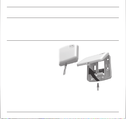
2. Remove the wiring
plate fr om the
Boiler Rel ay.
2.1 Carefully press a
screwdr iver into the
opening until t he
cover com es free.
2.2 Tilt the c over upwar ds
and remove it.
Page 3
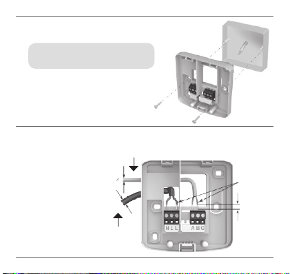
3. Mount the wiring plate
to the wall or wallb ox.
Note: the pl ugs and m ountin g
screws required are supplied.
4. Conn ect the Boiler Relay wiring.
Please re fer
to wiring
diagram
(right).
To heating appliance
<7mm 0
1,5-2,5mm
2
>7mm 0
Power
supply fr om
fused spur
max 6mm
Page 4
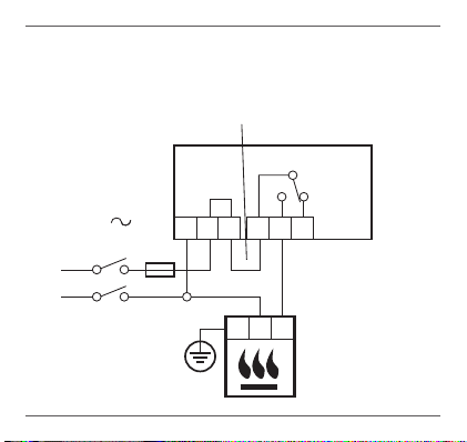
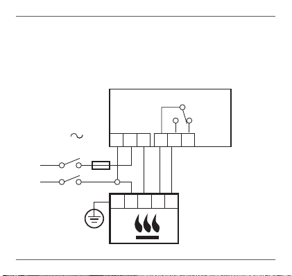
5.1 Wiring fo r a basic b oiler (not requ iring a pump overrun).
The boiler relay p owers th e boiler live input.
Place link here
230V
50-60Hz
L
N
<5A
BDR91
N L
L
A B C
N L
A-B:5(3)A
A-C:5(3)A
Page 5
5.2 Wiring for a boiler that re quire s a perma nent li ve.
For use with a boile r that req uires a permane nt live
(a typic al Comb i boile r wiring). This can be used for
boiler s with lo w voltag e or 230Vac room therm ostat
inputs. Please check manufacturer’s instructions.
230V
50-60Hz
L
N
<5A
BDR91
N L L
N L
A B C
A-B:5(3)A
A-C:5(3)A
Page 6

5.3 Wiring for a two- por t zone val ve.
For use with a boile r that req uires a permane nt live.
Please check manufacturer’s instructions.
G/ Y: Green/Yellow
230V
50-60Hz
L
BDR91
N L L
<5A
A B C
A-B:5(3)A
A-C:5(3)A
BL: Blue Motor Neu tral
BR: Brown Mo tor Live
GR: Grey End
O: Oran ge End
N
G/Y
BL BRMGR O
V4043H
Earth wire
switch (if used)
Permanent Live
switch (If u sed).
In wired sys tem
this typically
feeds the b oiler.
Page 7

6. Atta ch the Bo iler Re lay
to the wir ing plat e.
Hinge the housing downwards
and clic k into place.
Locate hi nges rs t
7. Re conne ct the m ains power to the Heati ng Appliance .
8. Locate the thermostat.
• Away from d raught s
• Away from h eat sour ces
• Away from d irect s unlight
• Positioned about 1.2m – 1.5m from the oor
continued overleaf
Page 8

9. First remove the dial.
10. Unclip the mo unting p late.
Press the top of the
thermo stat downwards , pull
it loose and tilt forwards.
Page 9

11. Mount direc tly to th e wall.
The plug s and mou nting
screws required are supplied.
12. Remove the p rotective ta b
between the batteries.
Plugs
Screws
Page 10

13. Attach the thermostat to
the mounting pl ate.
14. Repla ce the di al.
Step 1
Hook in her e
Step 2
Click int o place
Page 11

Binding to the Boiler Relay
The Single Zon e Therm ostat i s supplied ready to install,
binding is only re quire d if the T hermo stat an d Boile r Relay
are purchased separately.
Tou ch zo nes .
There are t wo touch zones just below the the rmost at
display, which are u sed to access me nus and fu nctions.
Page 12

1. First , set the B oiler R elay
into binding mod e by holding
down the BIND bu tton fo r
5 secon ds, unt il the re d
LED ashes 0.5 secon ds
on 0.5 se conds off.
2. You can now bin d the Sin gle
Zone Thermostat. Touch and
hold on the left touch zone for
approximately 10 seconds.
3. The scr een for b inding t he
Boiler R elay is now displ ayed.
Press here
10s
Page 13

4. When th e symbol ‘bo’ is fla shing, briefl y touch
the lef t touch zone to send t he binding sign al,
at which p oint th e
5. If binding has been suc cessf ul the number in dicat es
the signal str ength (1 = m in to 5 = max) .
If binding fails,
Successful binding Failed binding
6. The red L ED on the Boiler R elay wil l turn of f when binding
has bee n successful .
Note: bi nding c an be can celle d from th e bindi ng
screen by touching and holding on the lef t touc h
zone for app roximately 10 seco nds.
symbol will flash several times .
appea rs on scr een. Please t ry aga in.
Page 14

Installation Menu
The sing le Zone Therm ostat h as an Ins talla tion
Menu th at is use d to set th e minimu m and maximum
tempe ratur e limits and the off temperat ure set ting.
Maximum and minimum temperatures:
The max imum tem peratu re you can s et your
thermo stat to is 35ºC an d the min imum is 5ºC.
The off t empe ratu re:
If the thermostat is operated remotely, this is the temperature
value tha t is used w hen it is sw itche d off fro m the rem ote app.
Activate the Installation Menu as follows:
1. Rotate the set ting ring fully to
the lef t until t he minimum value
is shown . When th e value start s
flashing, touc h and hol d on both
left and right touch zones for
approximately 10 seconds.
10s 10s
Page 15

2. The maximum tempera ture
limit is now displ ayed. Th e
setting can be chang ed using
the set ting ri ng. The re is no
need to c onfirm t he value.
3. While th is setting is fl ashing ,
touch th e left touch zone
briefl y to displ ay the minimum
tempe ratur e limit . This ca n also
be changed usi ng the se tting ring.
4. Touch the le ft touch zone to
display the off tempe ratur e
setting. Cha nge this using
the set ting ri ng as before.
5. The Ins tallation Me nu clos es
automatically 10 seconds
after the last actio n.
Page 16

Approvals
Conforms to protection requirements
of the following directives:
EMC: 2004 /108/EC
LVD: 2006/95 /EC
R&TTE: 1999/05/EC
Hereby, Honey well, declare s that this
Single Zone Thermostat is in compliance
with the essential requirements and other
relevant pr ovisions of Dire ctive 1999/5/EC.
Manufac tured for and on beha lf of the
Environmental and Combustion Controls
Division of Honeywell Technologies Sàrl,
ACS-ECC EM EA, Z.A. La Piè ce 16,
1180 Rolle, Switze rland by its Author ised
Representative Honeywell Inc.
Need help? For assistance please visit:
www.honeywelluk.com
Honeywell Control Systems Ltd.
Skimped Hill Lane, Bracknell, Berkshire
RG12 1E B
WEEE Di rective
2012 /19 /E C
Waste Electrical
and Electronic
Equipment directive
•Attheendoftheproductlifedispose
of the pack aging and produc t in a
corresponding recycling centre.
•Donotdisposeoftheunitwith
the usual domestic refuse.
•Donotburntheproduct.
•Removethebatteries.
•Disposeofthebatteriesaccordingto
the local statutory requirements and
not with the usual domestic refuse.
3230188 9-001 A
 Loading...