

Page 1
W8525A,B Control Module
M4901
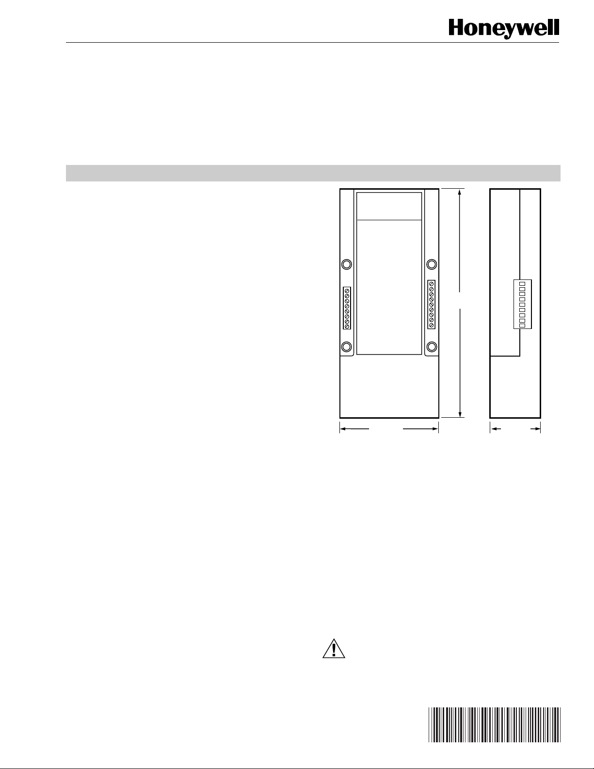
4-1/4 (108)
2-1/4 (57)
9-1/2
(241)
APPLICATION
The W8525A,B Control Module is used with the
T7525A/T7526A Touchpad Thermostats. The Control Module
contains the HVAC control relays, a microcontroller, and
associated circuitry. It communicates with the Utility Gateway
and Load Relay Module via power line carrier (PLC). It also
powers and communicates with the T7525A/T7526A
Touchpad Thermostats via a dedicated four-wire connection
over the thermostat wires. It acts as a messaging gateway
between the T7525A/T7526A Touchpad Thermostats and the
Utility Gateway.
IMPORTANT
The specifications given in this publication do not
include normal manufacturing tolerances. Therefore,
an individual unit may not exactly match the listed
specifications. Also, this product is tested and
calibrated under closely controlled conditions and
some minor differences in performance can be
expected when those conditions are changed.
for Echelon
INSTALLATION INSTRUCTIONS
Models:
❑ W8525A1009: Control Module (conventional HVAC
systems).
❑ W8525B1007: Control Module (heat pump systems).
Electrical Ratings:
Input Voltage: 120 Vac.
Environmental:
Operating Ambient Temperature: –4 to 150°F (–20 to 66°C).
Operating Relative Humidity: 5 to 90% rh, noncondensing.
Storage Temperature: –20 to 175°F (–29 to 80°C).
Terminals:
Terminal strip for connection to T7525A Touchpad
Thermostat.
Line Voltage Connections:
Three pigtail leads for line voltage wiring.
Mounting:
On 4 x 4 in. electrical box.
Dimensions:
See Fig. 1.
Weight:
2 lb (0.907 kg).
Fig. 1. W8525A,B Control Module approximate
dimensions in in. (mm).
INSTALLATION
When Installing this Product…
1. Read these instructions carefully. Failure to follow them
could damage the product or cause a hazardous
condition.
2. Check the ratings and description given on the product
to make sure the product is suitable for your
application.
3. Installer must comply with all local building codes and
ordinances when installing this product.
4. Installer must be a trained, experienced service
technician.
CAUTION
Disconnect power before installation to prevent
electrical shock or equipment damage.
Copyright © 1996 Honeywell Inc. • All Rights Reserved
69-0858-1
Page 2
W8525A,B CONTROL MODULE
Location
Mount the W8525A,B Control Module on a 4 x 4 in. electrical
box near the air handling equipment or other location where it
can be connected to the R, W, Y, and G wires for conventional
HVAC systems or R, W1/Y, G, and W2 wires for heat pump
HVAC systems with a common W1/Y wire.
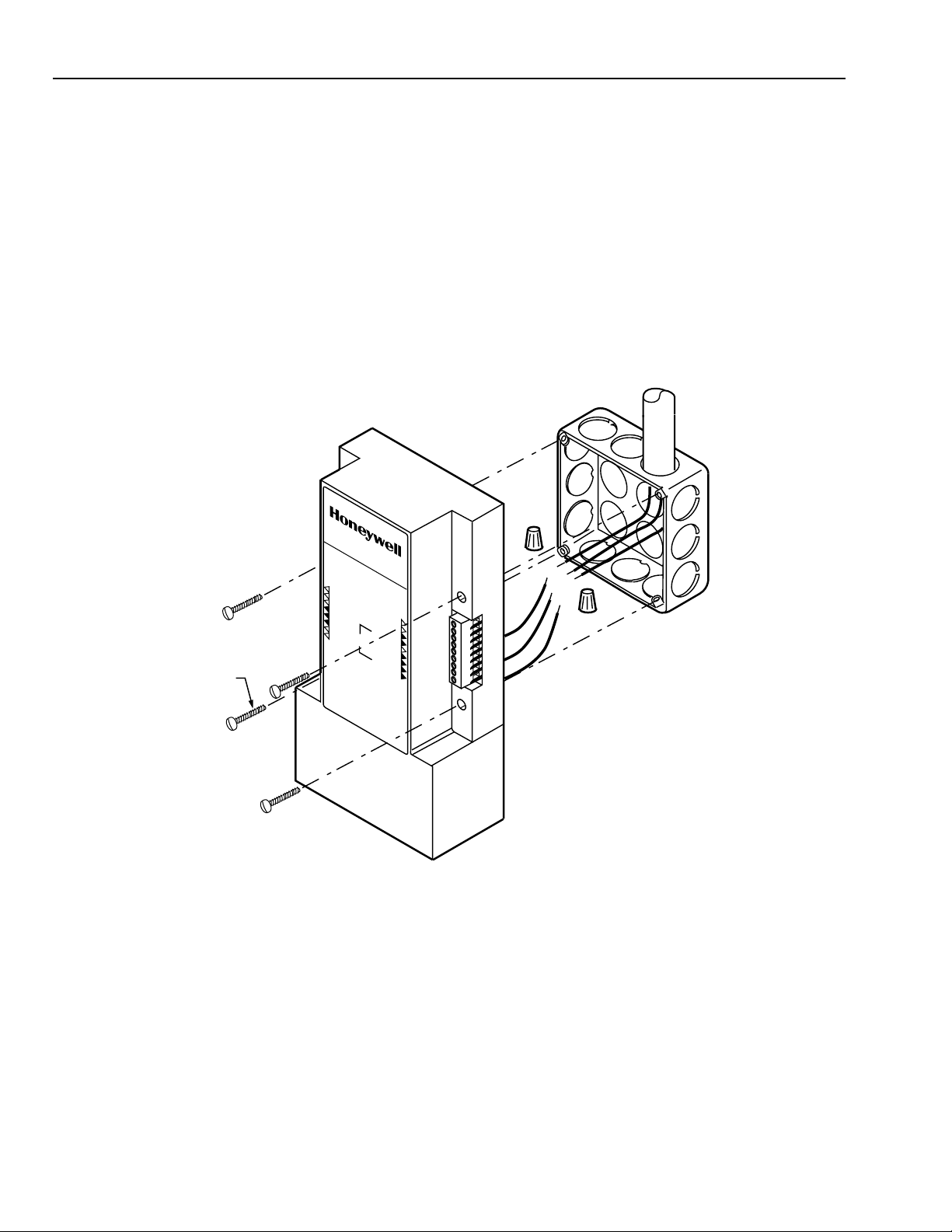
Mounting (Fig. 2)
A Remove the W8525A,B Control Module from its
package. Set aside any mounting materials (screws,
plastic screw anchors, etc.) until later in the mounting
procedure.
B Make sure that the location chosen is clear of studs and
other possible obstructions behind the drywall.
W8525A
C Place the electrical box on the wall at the selected
location and use it as a stencil to outline the portion of
the drywall to be cut away.
D Cut the opening for the electrical box.
E Mount the electrical box in the cutout.
F Run the line voltage wiring into the electrical box,
leaving a minimum of 3 in. (76 mm) of wire exposed in
the electrical box for connection to the Control Module.
G Connect the line voltage wires to the Control Module
pigtail leads using wire nuts.
H Mount the Control Module on the electrical box using
the screws supplied.
I Connect the four wires from the Touchpad Thermostat
and the wires from the HVAC equipment to be
controlled to the two terminal strips as shown in Figs. 3
and 4.
Y
G
W
6-32 (4)
TOUCHPAD
TO
R
c
R
G
R
O
U
N
P
D
O
W
E
R
C
H
O
IG
M
H
M
L
IM
I
T
Fig. 2. W8525A,B Control Module mounting on 4 x 4 in. electrical box.
M4800
69-0858—1
2
Page 3
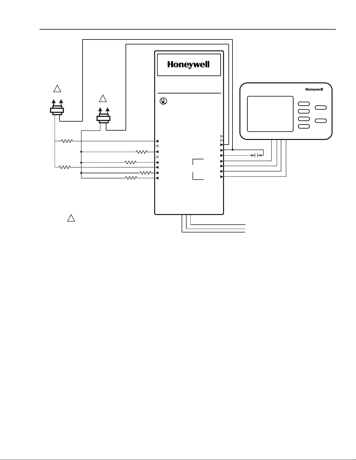
1
HOT NEUTRAL
STAGE 2
HEAT
EMERGENCY
HEAT RELAY
1
HOT NEUTRAL
STAGE 1 COMPRESSOR
FAN RELAY COIL
CHANGEOVER RELAY:
(COOL)
(HEAT)
W8525B
LISTED
58L9
ENCLOSED ENERGY MANAGEMENT EQUIPMENT
USED WITH T7525 OR T7526
THERMOSTAT TOUCHPAD
FOR SUPPLY CONNECTIONS, USE
APPROPRIATELY SIZED WIRE PER NEC
REQUIREMENTS, RATED FOR AT LEAST
75°C (167°F).
CLASS 2 WIRING
W2
Y1/W1
G
E
B
TOUCHPAD
O
TO
120 VAC
60 HZ
.5 AMP
RC
R
GROUND
POWER
COMM
HIGH LIMIT
L
W8525A,B CONTROL MODULE
Select
Back
FAULT MONITOR
BLACK
RED
GREEN
YELLOW
POWER SUPPLY. PROVIDE DISCONNECT MEANS
1
AND OVERLOAD PROTECTION AS REQUIRED.
Fig. 3. W8525A,B Control Module heat pump HVAC wiring.
CAUTION
TO REDUCE THE RISK OF FIRE OR
ELECTRIC SHOCK. DO NOT INTERCONNECT
THE OUTPUTS OF DIFFERENT
CLASS 2 CIRCUITS.
USE ONLY COPPER CONDUCTORS.
BLACK
WHITE
GREEN
HOT
NEUTRAL
GROUND
M4801
3
69-0858—1
Page 4

W8525A,B CONTROL MODULE
W8525A
1
HEATING VALVE OR RELAY
POWER SUPPLY. PROVIDE DISCONNECT MEANS
1
AND OVERLOAD PROTECTION AS REQUIRED.
1
HOT NEUTRALHOT NEUTRAL
COOLING
CONTRACTOR COIL
FAN RELAY COIL
Fig. 4. W8525A,B Control Module conventional HVAC wiring.
LISTED
58L9
ENCLOSED ENERGY MANAGEMENT EQUIPMENT
USED WITH T7525 OR T7526
THERMOSTAT TOUCHPAD
FOR SUPPLY CONNECTIONS, USE
APPROPRIATELY SIZED WIRE PER NEC
REQUIREMENTS, RATED FOR AT LEAST
75°C (167°F).
CLASS 2 WIRING
120 VAC
60 HZ
.5 AMP
Rc
R
Y
G
W
ELECTRIC SHOCK. DO NOT INTERCONNECT
USE ONLY COPPER CONDUCTORS.
TOUCHPAD
CAUTION
TO REDUCE THE RISK OF FIRE OR
THE OUTPUTS OF DIFFERENT
CLASS 2 CIRCUITS.
TO
GROUND
POWER
COMM
HIGH LIMIT
BLACK
RED
GREEN
YELLOW
BLACK
WHITE
GREEN
L1 (HOT)
L2 (NEUTRAL)
L3 (GROUND)
Select
Back
M4807
Home and Building Control
Honeywell Inc.
1985 Douglas Drive North
Golden Valley, MN 55422
Home and Building Control
Honeywell Limited-Honeywell Limitée
155 Gordon Baker Road
North York, Ontario
M2H 2C9
69-0858—1
69-0858—1 J.F. Rev. 1-96 Printed in U.S.A.
Helping You Control Your World
4
 Loading...