

Page 1
Excel 10
W7762A,B HYDRONIC CONTROLLERS
SPECIFICATION DATA
FEATURES
• LONMARK® HVAC profile #8020.
• Stand-alone operation or on high-speed 78 kilobit
Echelon
• Uses Echelon LonTalk
• FTT10A Transceiver.
• Direct connection of thermal actuators.
• Factory-configured default parameters.
• Wide range of supported valves and actuators.
• Available with setpoint knob for wall mounting.
®
LONWORKS© network.
®
protocol.
GENERAL
The W7762A and B Controllers are Hydronic Controllers in
the Excel 10 product line. They cover a wide range of control
applications including radiators, induction units, and fan coil
units with manual fan switching, and are suitable for either
wall mounting or unit mounting. The controllers can operate
as stand-alone units or networked using the standard
Echelon L
range of actuator types. Heating systems can be water or
electric, and cooling systems can be chilled water supply or
compressors. Extensive timing and interlock features make
the W7762 especially suitable for systems using electric heat
and compressors.
ONWORKS bus. Interfaces are provided for a wide
Table 2. Hydronic Controller models.
Model Inputs Control
Outputs
W7762A 2 2 X
W7762B 2 2
DESCRIPTION
The W7762A and B are LONMARK compliant Hydronic
Controllers in the Excel 10 family product line. These
controllers provide room temperature control using different
heating and cooling sequences. The controller is provided
with default configuration settings from the factory and is fully
operable on installation. Using standard Echelon
configuration tools, the controller can be configured with jobspecific settings. A variety of optional wall modules interface
with the Hydronic Controllers and provide any or all of the
following: setpoint adjustment, and an occupancy bypass
button. All wall modules include a space temperature sensor;
however, a remote C7068A return air sensor can also be
used.
Table 1. Supported output types.
Output Options
Heating Floating, thermal, PWM, on/off, multi-
Cooling Floating, thermal, PWM, on/off, multi-
Setpoint
knob
Internal
Sensor
stage electric.
stage compressor.
Bypass
Button
® U.S. Registered Trademark
Copyright © 1999 Honeywell Inc.
All Rights Reserved
74- 2934- 2
Page 2
W7762A,B HYDRONIC CONTROLLERS
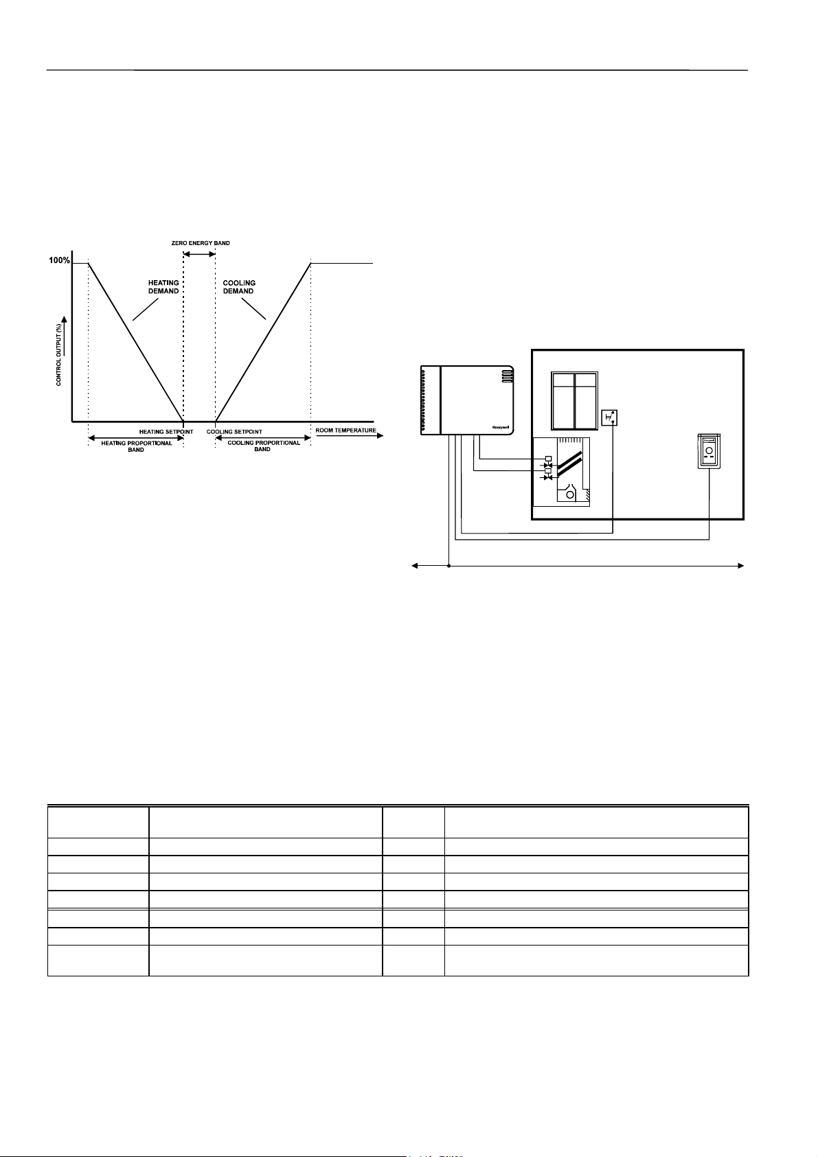
Sequences
Heat and cool sequences can be selected to be active or not
active, giving a total of four different sequence options:
- Heat only
- Cool only
- Heat/cool changeover
- Heat and cool sequence
Fig. 1. Operational sequence.
Window open
If the controller is configured for window open detection, the
controller automatically disables heat and cool control until
the window is closed again. Frost protection remains active.
Frost protection
If the temperature drops below 46°F (8°C), the controller
enables the heating circuit as frost protection.
Fan fail
When configured with an airflow detector, the controller
protects equipment by disabling the system when the fan
fails (for fan coil units with manual fan speed control).
Changeover
The controller operates two-pipe units configured with a
changeover input.
W7762B HYDRONIC
CONTROLLER
WINDOW
CONTACT
WALL MODULE
WITH TEMP
SENSOR
Modes of Operation
The controller has the following modes of operation.
Occupied mode
This is the normal operating condition for a room or zone
when it is occupied. The controller can be switched into this
Fig. 2. Typical application.
mode by a network command, by the room occupancy
sensor, or by a bypass button on the wall module.
SPECIFICATIONS
Standby mode
The standby mode saves energy by reducing heating or
cooling demand during periods where the room is temporarily
unoccupied.
Unoccupied mode
This mode is used for longer unoccupied periods, such as at
Models
The W7762A and W7762B are identical except for the
integral setpoint adjustment knob on the W7762A. The
W7762A can be ordered with setpoint adjustment in °C
absolute or °C relative.
night or during weekends and holidays.
Input/Output
See Table 3.
Table 3. Input/output specifications.
Inputs Function Pin
Number
Digital window/occupancy/changeover/airflow 4 closed ≤400 ohm (1.5 mA), open ≥10k ohm (4.8 V)
1,2
Digital
Override 7 closed ≤400 ohm, open ≥3.3k ohm
Analog Temperature sensor 9 20k ohm NTC (25°C)
1
Analog
Setpoint adjustment 8 10k ohm
Outputs
1
Digital
Override LED 6 0/5 Vdc (I<10 mA)
Triac (2 pairs)3Heat and cool 14,15
17,18
1
Wall module connection only.
2
Wall modules with fan speed switches must not be used.
3
See Table 1 for output type options.
Characteristics
24 Vac, 250 mA max. continuous,
650 mA max. surge (≤30 sec.)
E-BUSE-BUS
74-2934-2 2
Page 3

W7762A,B HYDRONIC CONTROLLERS
Power Supply
24 Vac ± 20%, 50/60 Hz.
Power Consumption
0.5 VA maximum (no load). See Excel 10 Hydronic Controller
System Engineering Guide, form number 74-2935 for
transformer sizing information.
Hardware design
Processor:
Neuron 3150
0.5 Kbyte of EEPROM on chip.
External memory:
EPROM, 64 Kbyte by 8.
Communication Interface:
Echelon transceiver FTT10A.
Compatible to Echelon Link Power Network.
LON service pin accessible on underside of housing.
LON LED visible through air vents on front of housing.
©
running at 5 MHz, with 2 Kbyte of RAM and
Specified Sensing Temperature Range
32° to 158°F (0° to 70°C)
Environmental Ratings
Operating temperature:
32° to 122°F (0° to 50°C)
Shipping/storage temperature:
-4° to 158°F (-20° to 70°C)
Relative humidity:
5% to 95% noncondensing
Dimensions
3-3/8 x 4-9/16 x 1-13/16 in. (86 x 116 x 46 mm)
Communications
The W7762 controllers use free topology transceivers (FTT)
and LonTalk bus protocol for communications. The E-Bus is
insensitive to polarity, eliminating wiring errors during
installation. The E-Bus is Link Power compatible.
The recommended wire size to be used for the E-Bus is level
IV 22 AWG (Belden part number 9D220150) or plenum rated
level IV 22 AWG (Belden part number 9H2201504)
nonshielded, twisted pair, solid conductor wire.
FTT networks can be in bus, star, loop or any combination of
these topologies. See E-Bus Wiring Practices, form number
74-2865, for more information including maximum lengths.
Mounting Options
W7762 Controllers can be mounted directly on a panel or
wall with two screws or it can be mounted with four screws on
a standard 60 mm junction box. The controller can be
mounted in any orientation desired.
LonMark Functional Profile
W7762 Hydronic Controllers support the LonMark Functional
Profile #8020 “Fan Coil Unit Controller”, version 2.0 (see
Fig. 3).
Hardware
Output
Fan Coil Unit Controller
Object #8020
nviSpaceTemp
nv1
SNVT_temp_p
nviSetPoint
nv2
SNVT_temp_p
nviFanSpeedCmd
nv6
SNVT_switch
nviOccCmd
nv7
SNVT_occupancy
nviApplicMode
nv8
SNVT_hvac_mode
nviSetPtOffset
nv9
SNVT_temp_p
nviWaterTemp
nv10
SNVT_temp_p
nviDischAirTemp
nv17
SNVT_temp_p
nviEnergyHoldOff
nv18
SNVT_switch
nviSensorOcc
SNVT_Occupancy
nviEmerg
SNVT_hvac_emerg
nviReheatRelay
SNVT_switch
NOT SUPPORTED.
Mandatory
Network
Var iables
Optional
Network
Variables
Configuration Properties
nc49 - nciSndHrtBt SNVT_time_sec mandatory
nc52 - nciMinOutTm SNVT_time_sec optional
nc48 - nciRcvHrtBt SNVT_time_sec optional
nc17 - nciLocation SNVT_str_asc optional
nc60 - nciSetPnts
nc59 - nciNumValve
SNVT_temp_setpt
SNVT_count
Manufacturer
Defined
Section
Hardware
Input
nvoHeatOutput
nv3
SNVT_lev_percent
nvoCoolOutput
nv4
SNVT_lev_percent
nvoFanSpeed
nv5
SNVT_switch
nvoTerminalLoad
nv11
SNVT_lev_percent
nvoLoadAbs
nv12
SNVT_power
nvoDischAirTemp
nv13
SNVT_temp_p
nvoReheat
nv14
SNVT_switch
nvoSpaceTemp
nv15
SNVT_temp_p
nvoEffectSetPt
nv16
SNVT_temp_p
nvoEffectOcc
nv19
SNVT_occupancy
nvoEnergyHoldOff
nv20
SNVT_switch
nvoUnitStatus
nv21
SNVT_hvac_status
mandatory
optional
nvoSensorOcc
SNVT_occupancy
nvoDigitInState
SNVT_switch
Fig. 3. LonMark object details.
3 74-2934-2
Page 4

W7762A,B HYDRONIC CONTROLLERS
R
Approvals and Standards
CE
EN50081-1
EN50082-1
meets FCC part 15 class B requirements
OCCUPANCY SENSOR
CHANGEOVER CONTACT
AIRFLOW CONTACT
WINDOW CONTACT
MOTION SENSOR
WALL MODULE
CONNECTIONS
Accessories
Excel 10 T7460 Wall Modules
Excel 10 T7560 Wall Modules
Excel 10 T7770 Wall Modules
Excel 10 FTT/LPT 209541B Termination Module
C7068A Return Air Sensor (Europe only)
M7410C Small Electric Linear Valve Actuator (Europe only)
Z100 Thermoelectric Actuator (Europe only)
W7762 HYDRONIC CONTROLLE
D
T
E
U
O
S
N
1
T
O
2
3
4
5
6
7
8
9
10
N
N
D
D
LED
BYPASS
SETPT
SENSOR
GND
D
E
U
S
O
T
U
S
D
E
T
I
A
G
I
N
I
U
L
P
T
D
N
G
Wall module setpoint connection for W7762B only.
Fig. 4. Input/output details.
24 VAC COM
OUT 1 COM
OUT 1 OPEN
OUT 1 CLOSE
OUT 2 COM
OUT 2 OPEN
OUT 2 CLOSE
E-BUS (LON)
E-BUS (LON)
24 VAC
24 VAC
11
12
13
14
15
16
17
18
19
20
24 VAC COM
COM
OPEN
CLOSE
LONW
L
ONWORKS
HEAT
+
ORKS
NETWORK IN
NETWORK OUT
COM
OPEN
CLOSE
120/240 VAC
COOL
-
Table 3. Output assignments for various actuator types.
Output type Out 1 Terminal Out 2 Terminal
13 14 15 16 17 18
Floating 24 Vac open close 24 Vac open close
1-stage 24 Vac on/off — 24 Vac on/off —
2-stage 24 Vac stage 1 stage 2 24 Vac stage 1 stage 2
3-stage 24 Vac stage 1 stage 2 24 Vac stage 1 stage 2
stage 3 stage 3
PWM 24 Vac PWM — 24 Vac PWM —
Thermal 24 Vac on/off — 24 Vac on/off —
Home and Building Control Home and Building Control Home and Building Control Products
Honeywell Inc. Honeywell Limited-Honeywell Limitee Honeywell AG
Honeywell Plaza 155 Gordon Baker Road Böblinger Straβe 17
P.O. Box 524 North York, Ontario D-71101 Schönaich
Minneapolis, MN 55408-0524 M2H 3N7 Germany
USA Canada
http://www.honeywell.com http://www.honeywell.ca http://europe.hbc.honeywell.com
74-2934-2 Rev. 01-01 printed in Germany Subject to change without notice
 Loading...