

Page 1
BEFORE INSTALLATION
The Excel 10 Hydronic Controller is available in the following
two models:
1. W7762A—with integral setpoint adjustment.
2. W7762B—no integral setpoint adjustment.
Excel 10
W7762A,B HYDRONIC CONTROLLERS
INSTALLATION INSTRUCTIONS
Wiring
All wiring must comply with applicable electrical codes and
ordinances. Refer to job or manufacturers’ drawings for
details.
The models all have similar housings and mounting
procedures.
IMPORTANT
It is recommended that devices be kept at room
temperature for at least 24 hours before applying
power to allow any condensation resulting from low
shipping/storage temperatures to evaporate.
INSTALLATION
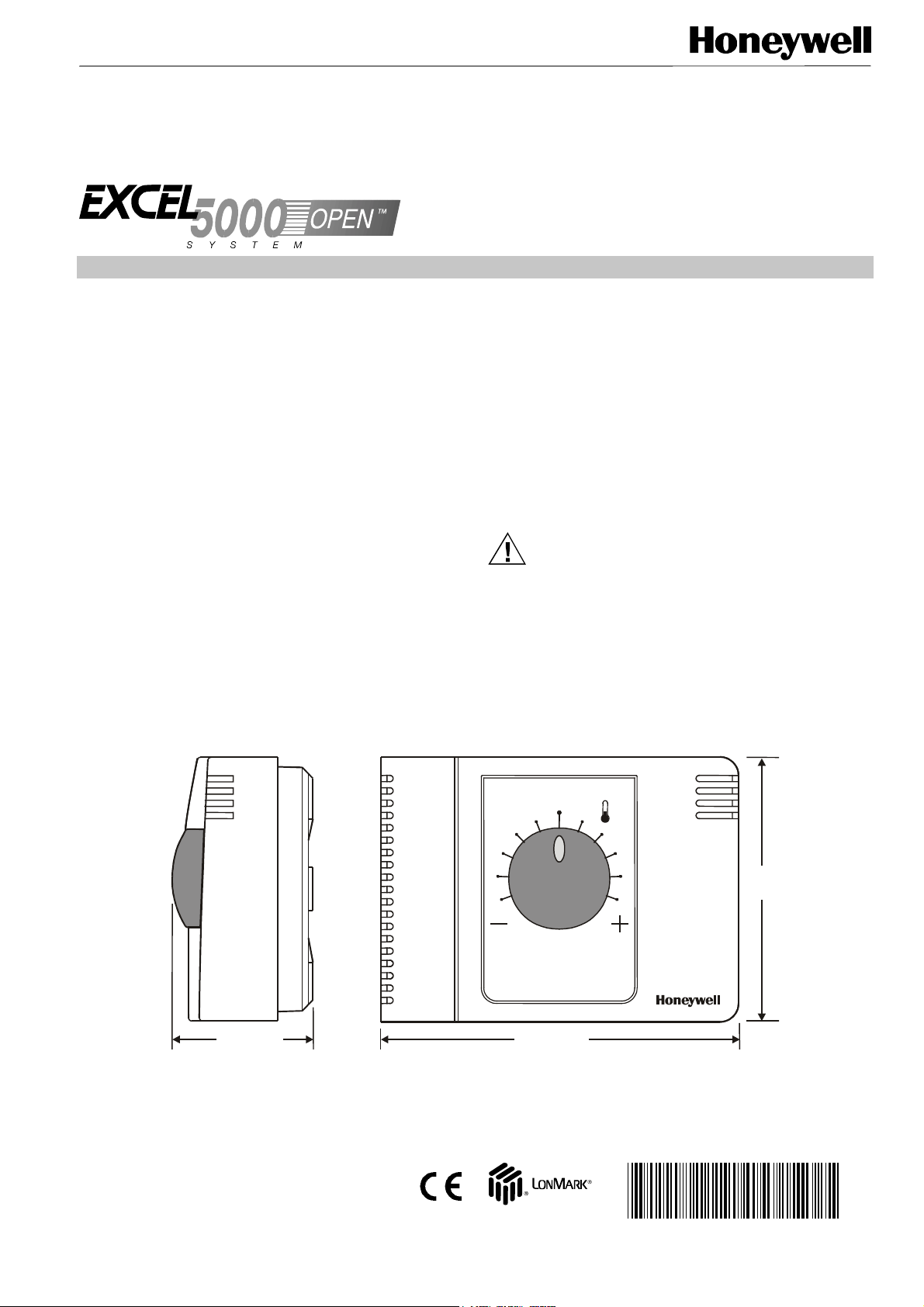
W7762 Hydronic Controllers can be mounted on a panel or
wall or onto a standard 60-mm wall outlet box using No. 6
(3.5 mm) screws. See Fig. 1 for outside dimensions and
Fig. 2 for subbase mounting dimensions.
The controller can be mounted in any orientation desired.
Power
Input power provided must be 24 Vac (±20%), 50 or 60 Hz.
For US installation, power must come from an energy-limited
Class II Power Source (transformers must not exceed
100 VA). More than one W7762 Controller can be powered
by a single transformer.
CAUTION
Turn off power prior to connecting to or removing
connections from any terminals to avoid electrical
shock or equipment damage.
Use the heaviest gauge wire available, up to 14 AWG
(2.5 mm
wiring.
2)
with a minimum of 18 AWG (1.0 mm2) for all power
1-13/16 (46)
® U.S. Registered Trademark
Copyright © 2000 Honeywell Inc.
All Rights Reserved
4-9/16 (116)
Fig. 1. Excel 10 Hydronic Controller outside dimensions in in. (mm).
3-3/8
(86)
95- 7563- 3
Page 2
W7762A,B HYDRONIC CONTROLLERS
ONIC CO
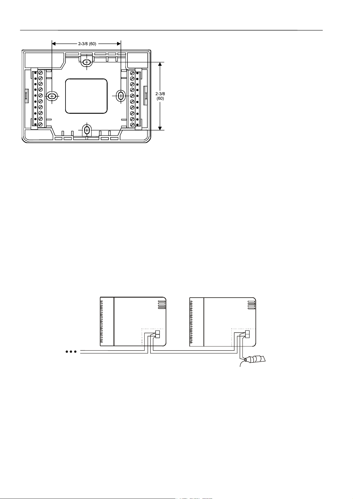
Fig. 2. Subbase mounting dimensions.
IMPORTANT (US only)
If the W7762 Controller is used on UL 1995 Heating
and Cooling Equipment and the transformer
primary power is more than 150 Vac, connect the
transformer’s secondary to earth ground. For these
applications, only one Excel 10 controller can be
powered by each transformer.
Communications
Wire the controller communications E-Bus using level IV 22
AWG (Belden part number 9D220150) or plenum-rated level
IV 22 AWG (Belden part number 9H2201504) nonshielded,
twisted pair, solid conductor wire. When possible, use
Honeywell AK3781, AK3782, AK3791, or AK3792 cable (US
part numbers). See E-Bus Wiring Practices, form number
74-2865, for more information including maximum lengths.
Pull the cable to each controller on the E-Bus and connect to
terminals 19 and 20.
The W7762 Hydronic Controller utilizes a free topology transceiver (FTT10A) Link Power compatible E-Bus that allows
daisy-chain, loop, and star network configurations or any
combination thereof. Depending upon the E-Bus configuration used, one or two termination modules, part number
209541B, may be required. Different connections to the
termination module are necessary depending upon whether it
is used in a singly- or doubly-terminated network configuration. See Excel 10 FTT/LPT 209541B Termination
Module Installation Instructions, form 95-7554.
NOTES:
— The E-Bus is insensitive to polarity, eliminating
installation errors due to miswiring.
— Do not bundle output wires with sensor, digital input or
communications bus wires. Maintain a minimum 3-in.
(76-mm) separation between E-Bus and Triac output and
power supply wiring.
— For installations, try to avoid areas of high electro-
magnetic noise (EMI).
— Some T7770 Wall Modules used with Hydronic con-
trollers have a daisy-chain connection for the E-Bus to
provide network access via built-in jack.
— For more information; see E-Bus Wiring Guidelines, form
number 74-2865.
Wall Modules
A variety of Excel 10 wall modules can be used with W7762
Hydronic Controllers. See T7460 Wall Modules Installation
Instructions, form number 95-7610; T7560 Digital Wall
Module Installation Instructions, form number 95-7620; and
T7770 Wall Modules Installation Instructions, form number
95-7538 for installation details.
NOTE: Wall Modules with fan speed switches must not be
used with W7762 controllers.
W7762 HYDRONIC CONTROLLER
19
20
Fig. 3. Termination module connection (daisy-chain network configuration).
95-7563-3 2
W7762 HYDR
NTROLLER
ORANGE
19
20
BROWN
TERMINATION
MODULE (209541B)
Page 3

W7762A,B HYDRONIC CONTROLLERS
Wiring Details
Connections to the Hydronic controllers are made at 2
internal terminal blocks accessible beneath the front cover.
No tools are required to remove the front cover. Simply pull
away from the subbase as shown in Fig. 4.
Fig. 4. Terminal cover removal.
IMPORTANT
Screw-type terminal blocks are designed to accept
no more than one 14 AWG (2.5 mm
Multiple wires that are 14 AWG (2.5 mm
2
) conductor.
2
connected with a wire nut. Include a pigtail with this
wire group and attach the pigtail to the individual
terminal block.
Wire to the terminal blocks as follows:
1. Strip 1/2 in. (13 mm) insulation from the conductor.
2. Insert the wire in the required terminal location and
tighten the screw to complete the termination. Ensure
that the wire entering the terminal block does not extend above the numbered face of the terminal block to
avoid contact between the wires and the printed circuit
board on the underside of the front cover (see Fig. 6.)
) can be
Fig. 5. Mounting on wall outlet box.
Use a minimum wire size of 20 AWG (0.5 mm
2
) for all input /
output connections. The maximum length of all input/output
cables and wall module interface cables is 65 ft (20 m). Maintain 3 in. (76 mm) minimum spacing between signal lines 110 and Triac output and power supply wiring.
Fig. 8 illustrates the terminal assignments of the controllers.
Table 1 lists Triac output assignments for various actuator
types. Refer to job drawings for specific wiring diagrams.
Fig. 6. Terminal block connections.
IMPORTANT
When two or more wires are to be attached to the
same terminal, be sure to twist them together.
Deviations from this rule can result in improper
electrical contact. See Fig. 7. Local wiring codes
may take precedence over this recommendation.
3 95-7563-3
Page 4

W7762A,B HYDRONIC CONTROLLERS
1. STRIP 1/2 IN. (13 MM) FROM WIRES
TO BE ATTACHED AT ONE
TERMAINAL
OCCUPANCY SENSOR,
CHANGEOVER CONTACT,
AIRFLOW CONTACT,
WINDOW CONTACT,
MOTION SENSOR, etc.
6
T7560A,
T7460A,
T7460B, or
T7460E
WALL MODULE
5
4
3
2
1
Output type Out 1 Terminal Out 2 Terminal
Floating 24 Vac open close 24 Vac open close
1-stage 24 Vac on/off — 24 Vac on/off —
2-stage 24 Vac stage 1 stage 2 24 Vac stage 1 stage 2
3-stage 24 Vac stage 1 stage 2 24 Vac stage 1 stage 2
PWM 24 Vac PWM — 24 Vac PWM —
Thermal 24 Vac on/off — 24 Vac on/off —
2. TWIST WIRES TOGETHER WITH
PLIERS (A MINIMUM OF THREE
TURNS).
3. CUT TWISTED END OF WIRES TO 3/16 IN. (5 MM) BEFORE
INSERTING INTO T ERMINAL AND TIGHTENI NG SCREW. THE N
PULL ON EACH WIRE IN ALL TERMINALS TO CHECK FOR GOOD
MECHANICAL CONNECTION.
Fig. 7. Attaching two or more wires at terminal blocks.
W7762 HYDRONIC CONTROLLER
NOT USED
1
NOT USED
2
NOT USED
3
DIGITAL INPUT
4
DGND
5
LED
6
7
BYPASS
8
SETPT (for W7762B, only)
9
SENSOR
10
GND
24 VAC
24 VAC COM
OUT 1 COM
OUT 1 OPEN
OUT 1 CLOSE
OUT 2 COM
OUT 2 OPEN
OUT 2 CLOSE
E-BUS (LON)
E-BUS (LON)
24 VAC
11
24 VAC COM
12
COM
13
OPEN
14
CLOSE
15
COM
16
OP EN
17
CLO SE
18
19
20
LONWORKS NETWORK IN
LONWORKS NETWORK OUT
Fig. 8. Hydronic Controller terminal assignments.
Table 1. Output assignments for various actuator types.
13 14 15 16 17 18
stage 3 stage 3
120/240 VAC
HEAT
+
COOL
-
Home and Building Control Home and Building Control Home and Building Control Products
Honeywell Inc. Honeywell Limited-Honeywell Limitee Honeywell AG
Honeywell Plaza 155 Gordon Baker Road Böblinger Straβe 17
P.O. Box 524 North York, Ontario D-71101 Schönaich
Minneapolis, MN 55408-0524 M2H 3N7 Germany
USA Canada
http://www.honeywell.com http://www.honeywell.ca http://europe.hbc.honeywell.com
95-7563-3 Rev. 01-01 7157 351 printed in Germany Subject to change without notice
 Loading...