

Page 1
HONEYWELL EXCEL 5000 OPEN SYSTEM
FEATURES
LONMARK® HVAC profile #8020
Stand-alone operation or on high-speed 78 kilobit
Uses Echelon LonTalk
FTT10A Transceiver
Direct connection of thermal actuators
Direct connection to fan switch
Direct and indirect connection to electrical heat
Factory-configured default parameters
Wide range of supported valves and actuators
Interlocks and time delays to protect equipment
Connected floating actuators exercised once a week
Slim design fits into narrow fan coil units
Terminals all on one side allow controllers to be
GENERAL
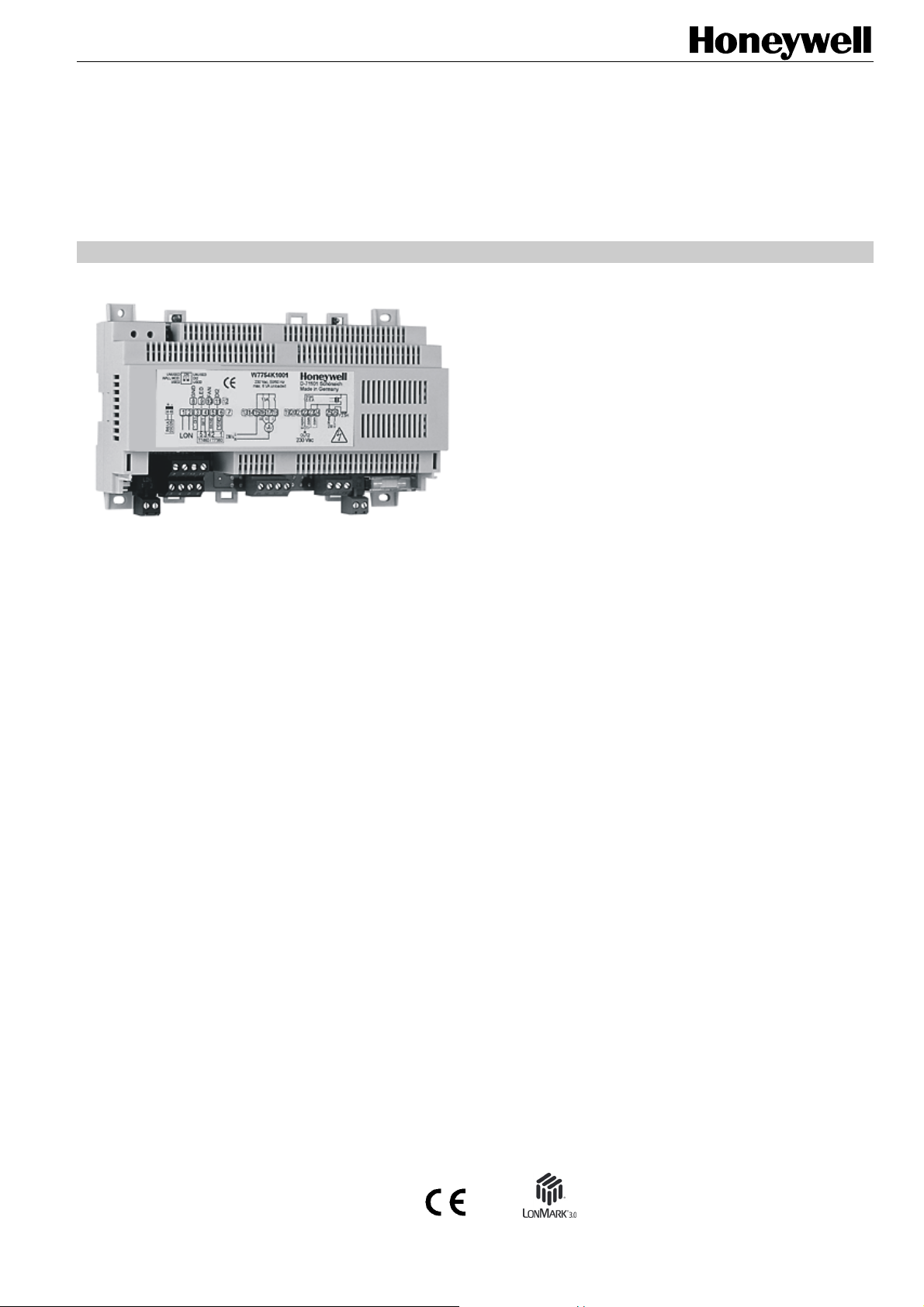
The W7754 is a configurable fan coil unit application
controller belonging to the Excel 10 product line for
maintained zones. The W7754 covers a wide range of fan coil
control applications and can operate as a stand-alone unit or
networked using the standard Echelon L
Interfaces are provided for a wide range of actuator types.
Heating systems can be water or electrical, and cooling
systems can be chilled water supply or compressors.
Extensive timing and interlock features make the W7754
especially suitable for systems using electrical heat and
compressors.
ONWORKS
®
bus.
Power supplied by power mains or 24 V
DESCRIPTION
The W7754K,P,Q Controllers provide room temperature
control for two- and four-pipe fan coil units with optional
electrical heating coils (W7754K and W7754P) and can
control single-, two-, or three-speed fans. The units are
provided with default configuration settings from the factory
and are fully operable upon installation. Using standard
Echelon configuration tools, the units can be configured with
job-specific settings. A variety of optional wall modules
interface with the units and provide any or all of the following:
setpoint adjustment, fan speed adjustment, and an occupancy
bypass button. All wall modules include a space temperature
sensor; however, a remote C7068A return air sensor can also
be used.
Excel 10
W7754K,P,Q FCU CONTROLLERS
SPECIFICATION DATA
Echelon® LONWORKS© network
positioned at back of fan coil unit
®
protocol
® U.S. Registered Trademark
Copyright © 2010 Honeywell Inc. • All Rights Reserved EN0B-0453GE51 R0110
Page 2
W7754K,P,Q FCU CONTROLLERS
Table 1. Overview of equipment (by model)
OS Number
power
supply
digital outputs
digital
inputs
analog inputs
relay
relay
relay
rd
th
triac (open OUT1)"
triac (close OUT1)
triac (open OUT2)
triac (close OUT2)
low-voltage PWM
control of solid-
state relay
LED
configurable digital
input
digital input
(window contact)
AI (fan speed +
occupancy override
switches)
analog input (room
sensor)
analog input (set-
point adjustment
3
4
switch)
230
24
relay
st
1
nd
2
W7754K1001 X X X X X X X X X X X X
W7754P1000 X X X X X X X X X X X X X X X
W7754Q1008 X X X X X X X X X X X X X X X
Sequences
Heat and cool sequences can be selected to be active or not
active, giving a total of eight different sequence options (each
can be with or without fan control):
Heat, only
Cool, only
Heat/cool changeover
Heat and cool sequence
All of the above, plus electrical reheat.
"Unoccupied" Mode
This mode is used for longer unoccupied periods, such as at
night or during weekends and holidays.
Window Open
If the controllers are configured for window open detection,
they automatically disables heat and cool control until the
window is closed again. Frost protection remains active.
Frost Protection
If the temperature drops below 46°F (8°C), the controllers
enable the heating circuit as frost protection.
Smoke Control
The fan can be turned ON or OFF by network command for
smoke control.
Fan Failure
When configured with an air flow detector, the controllers
protect equipment by disabling the system when the fan fails.
Changeover
The controllers operate two-pipe fan-coil units configured with
a changeover input.
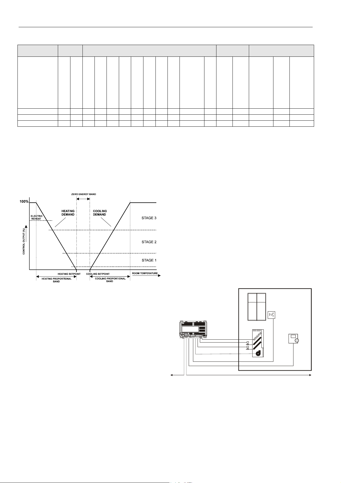
Fig. 1. Operational sequence
Modes of Operation
The units have the following modes of operation.
"Occupied" Mode
This is the normal operating condition for a room or zone
when it is occupied. The controllers can be switched into this
mode by a network command, by the room occupancy sensor, or by a bypass button on the wall module. In the
"occupied" mode, the fan is controlled by the setting of the fan
speed switch on the wall module or, when the switch is set to
“auto,” by the control algorithm. The fan can be configured to
remain ON or turn OFF during the zero energy band.
"Standby" Mode
The "standby" mode saves energy by reducing heating or
cooling demand during periods where the room is temporarily
unoccupied. In this mode, the fan is switched OFF within the
zero energy band.
e.g. Excel 10 W7754
FCU Controller
LonWorks network
Honeywell
D-71101 Schönaich
Made in Germany
Fig. 2. Typical application
window
contact
Excel 10
wall module
EN0B-0453GE51 R0110
2
Page 3

W7754K,P,Q FCU CONTROLLERS
SPECIFICATIONS
Models
All three models are equipped with a minimum of three relays,
one LED digital output, three digital inputs, and two analog
inputs.
Input/Output
Table 2. Input/output specifications
function/characteristics
1st digital
input
1st
analog
input
2nd
analog
input
1st digital
output
3rd
analog
input
2nd
digital
input
4th relay W7754P,Q only; permanently configured to
1st, 2nd,
and 3
relays
triac
outputs
2nd
digital
output
all models; configurable (using LNS plug-in) to
read input from hardwired window contact, occupancy sensor, etc.; suitable for dry contacts,
only; max. voltage at open contact = 5 Vdc
all models; permanently configured to read input from hardwired wall module's temperature
setpoint adjustment knob; enabled / disabled
using left DIP switch
all models; permanently configured to read input from hardwired wall module's room temperature sensor (for use with an NTC20k
sensor, only; accuracy [w/o sensor] = 0.5 °C at
25 °C); enabled/disabled using left DIP switch
all models; permanently configured to write output to LED of hardwired wall module; enabled /
disabled using left DIP switch; max. voltage =
5 Vdc; max. current = 5 mA
all models; permanently configured to read input from hardwired wall module's 3-speed fan
control knob and "occupancy override" button;
enabled / disabled using left DIP switch
all models; permanently configured to read input from window contact; enabled / disabled
using right DIP switch; suitable for dry contacts, only; max. voltage at open contact =
5 Vdc
write output to hardwired electrical reheat coil;
switching voltage = 24...230 Vac; switching
current = 0.05...10 A
all models; permanently configured to write out-
rd
put to hardwired 3-speed fan; switching voltage
= 24...230 Vac; switching current = 0.05...3 A
(max. 3 A for all three relays together)
number varies according to model: permanently
configured to write output to OUT1/2; switching
voltage = 230 Vac (230-V models) or 24 Vac
(24-V models), max. switching current = 0.5 A;
max. peak (10 sec) current = 1 A
W7754K, only; suitable for attachment to a
solid-state relay (max. voltage = 12 Vdc; max.
current = 12 mA at 10 Vdc) for low-voltage
PWM control in high-current electrical reheat
applications (see section "Accessories")
Power Supply
W7754K,P: 230 Vac +10%, -15%, 50/60 Hz
W7754Q: 24 Vac 20%, 50/60 Hz
Power Consumption
See Table 2.
Hardware Design
Processor: Neuron 3150® running at 5 MHz, with 2 kB
of RAM and 0.5 kB of EEPROM on chip.
Ext. memory: EPROM, 64 kB by 8.
Specified Sensing Temperature Range
32° to 104°F (0° to 40°C)
Approvals, Certifications, and Standards
Approvals and Certifications
CE-approved
Certified as per LonMark® Application Layer
Guidelines V 3.0, thus interoperable with all other
devices in open L
devices)
EUBAC-certified as follows:
W7754P1000:
W7754Q1008:
ONWORKS® networks (incl. 3
eu.bac
020885
Cert
eu.bac
020706
Cert
rd
-party
Classification according to EN60730-1
Environmental conditions: For use in home (residential,
commercial, and light-industrial)
environments
Pollution degree: Class 2
Protection against shock: Class 0 (without terminal cover)
Class II (with terminal cover)
Software class: Class A
Classification according to EN60529
(Degree of Protection Provided by Enclosures)
Without terminal cover: IP20
With terminal cover: IP30
Ambient Environmental Limits
Operating temperature: 0 … +50 °C at 5…90% r.H.
Storage temperature: -40 … +70 °C at 5…90% r.H.
W7754P1000, W7754Q1008 Temperature Control
Accuracy (CA)
(min. CA values requested by EUBAC for fan coil unit
applications: ≤ 1.4 K)
FCU heating mode: 0.5 K
FCU cooling mode: 0.2 K
Dimensions (W x L x H)
Without terminal cover: W x L x H = 110 x 180 x 60 mm
With terminal cover: W x L x H = 130 x 180 x 60 mm
Weight
W7754K,P: 420 g; W7754Q: 260 g
3
EN0B-0453GE51 R0110
Page 4

W7754K,P,Q FCU CONTROLLERS
Communications
The controllers use the LonTalk protocol. They support the
L
ONMARK Functional Profile # 8020 “Fan Coil Unit Controller”,
version 2.0. Fig. 6 shows the implementation used.
The recommended wire size to be used for the L
Bus is level IV 22 AWG (Belden part no. 9D220150) or
plenum rated level IV 22 AWG (Belden part no. 9H2201504)
non-shielded, twisted pair, solid conductor wire.
FTT networks can be in bus, star, loop or any combination of
these topologies.
ONWORKS
Mounting Options
The controllers are suitable for mounting on a standard rail
(DIN EN 50022-35 x 7,5), on walls/ceilings, as well as for
installation in wiring cabinets or fuse boxes.
Accessories
Excel 10 T7460 Wall Modules
Excel 10 T7560 Wall Modules
Excel 10 FTT/LPT 209541B Termination Module
C7068A Return Air Sensor (Europe, only)
M7410C Small Electric Linear Valve Actuator (Europe,
only)
Z100 Thermoelectric Actuator (Europe, only)
XAL-COV-L Terminal Protection Covers (8 pcs. bulk)
Solid-state relay from Carlo Gavazzi (part no.:
RS1A23D25-P64) with 40-cm cable and plug, for
230 Vac and max. 25 A (AC
XAL-Term, L
for DIN rail
ONWORKS connection/termination module
rms
)
EN0B-0453GE51 R0110
4
Page 5

W7754K,P,Q FCU CONTROLLERS
+ -
RS1A
23D25
21 4
LON
GND9LED10FAN11DI2
8
5
3
DI1
SET
SENS
5
3
42 1
T7460 / T7560
12
6 23
7
GND
L
230 V
N
3A
131415 18
16
17
III II I
fan
1920
Fig. 3. W7754K sticker with input/output details
21 4
LON
GND9LED10FAN11DI2
8
5
3
DI1
SET
SENS
5
3
42 1
T7460 / T7560
12
6 23
7
GND
L
230 V
N
3A10A
131415 18
16
17
III II I
fan
1920
open
close
OUT1 OUT2
230 Vac
Fig. 4. W7754P sticker with input/output details
21 4
LON
GND9LED10FAN11DI2
8
5
3
DI1
SET
SENS
5
3
42 1
T7460 / T7560
12
6 23
7
GND
L
230 V
N
3A10A
131415 18
16
17
III II I
fan
1920
open
close
OUT1 OUT2
24 Vac
Fig. 5. W7754Q sticker with input/output details
CAUTION
In order to conform to IP30, when installed on walls or
ceilings, the unit must be equipped with the optional
terminal protection cover.
Ho ne ywe l l
D-71101 Schönaich
Made in Germany
triac
0.5 A
2526
24
2122
com
com
open
OUT2
230 Vac
Ho ne ywe l l
D-71101 Schönaich
Made in Germany
2122
open
close
Honeywell
D-71101 Schönaich
Made in Germany
2122
open
close
triac
0.5 A
triac
0.5 A
230 V
2526
24
com
com
230 V
2526
24
~~
com
com
24 Vac
Hardware
Output
Fan Coil Unit Controller
Object #8020
F2.5H
LN
F2.5H
LN
F2.5H
nviSpaceTemp
nv1
SNVT_temp_p
nviSetPoint
nv2
SNVT_temp_p
nviFanSpeedCmd
nv6
SNVT_switch
nviOccCmd
nv7
SNVT_occupancy
nviApplicMode
nv8
SNVT_hvac_mode
nviSetPtOffset
nv9
SNVT_temp_p
nviWaterTemp
nv10
SNVT_temp_p
nviDischAirTemp
nv17
SNVT_temp_p
nviEnergyHoldOff
nv18
SNVT_switch
Mandatory
Network
Variables
Optional
Network
Variables
nvoHeatOutput
nv3
SNVT_lev_percent
nvoCoolOutput
nv4
SNVT_lev_percent
nvoFanSpeed
nv5
SNVT_switch
nvoTerminalLoad
nv11
SNVT_lev_percent
nvoLoadAbs
nv12
SNVT_power
nvoDischAirTemp
nv13
SNVT_temp_p
nvoReheat
nv14
SNVT_switch
nvoSpaceTemp
nv15
SNVT_temp_p
nvoEffectSetPt
nv16
SNVT_temp_p
nvoEffectOcc
nv19
SNVT_occupancy
nvoEnergyHoldOff
nv20
SNVT_switch
nvoUnitStatus
nv21
SNVT_hvac_status
Configuration Properties
nc49 - nciSndHrtBt SNVT_time_sec mandatory
nc52 - nciMinOutTm SNVT_time_sec optional
nc48 - nciRcvHrtBt SNVT_time_sec optional
nc17 - nciLocation SNVT_str_asc optional
nc60 - nciSetPnts
nc59 - nciNumValve
nviSensorOcc
SNVT_Occupancy
nviEmerg
SNVT_hvac_emerg
nviReheatRelay
SNVT_switch
SNVT_temp_setpt
SNVT_count
Manufacturer
Defined
Section
mandatory
optional
nvoSensorOcc
SNVT_occupancy
nvoDigitInState
SNVT_switch
Hardware
NOT SUPPORTED.
Fig. 6. L
Input
ONMARK object details
Manufactured for and on behalf of the Environmental and Combustion Controls Division of Honeywell Technologies Sàrl, Rolle, Z.A. La Pièce 16, Switzerland by its Authorized Representative:
Automation and Control Solutions
Honeywell GmbH
Böblinger Strasse 17
71101 Schönaich / Germany
Phone: (49) 7031 63701
Fax: (49) 7031 637493
http://ecc.emea.honeywell.com
Subject to change without notice. Printed in Germany
EN0B-0453GE51 R0110
 Loading...